Embed Size (px)
Citation preview

1
THERMICA Spacecraft Thermal Design System
4151 W. Lindbergh Way, Chandler Arizona 85226Phone: 480-756-0512 Fax: 480-820-1991 email: [email protected] web: www.sinda.com
Proven Software without Compromise
About Network Analysis
• 36 year history with SINDA• Associated with SINDA (CINDA) since 1963• Started selling and supporting a proprietary version of SINDA
(now called SINDA/G) in 1982.
• Commercial & Govt. Customers Worldwide • UK, Europe, Japan/Asia, Israel, Argentina• NASA, JPL, Los Alamos, Argonne, NASDA, ISAS,
CAS/CAST, CONAE, CONIDA, DRA • Provides experienced thermal engineer tech support, on-site
training, comprehensive s/w maintenance program
• Staff– Highly experienced thermal engineers– Marketing, Sales professionals with engineering backgrounds
2
3
SINDA/G - A World Wide Standard for Advanced Thermal Modeling
United States
Europe• Northern Ireland• England• France• Spain• Italy• Germany• Austria• Netherlands
Japan
Taiwan
IsraelCanada
Korea
P.R.China
Indonesia
AustraliaPeru
Argentina
Singapore
South Africa
Tech Support via Web Conferencing
• Anyone in conference can share documents, such as PowerPoint training slides or Word documents.
• Live video (not too useful, but at least we can wave and say hi!)
• Share an electronic whiteboard among all the participants (anyone may draw), or watch us draw on our wall sized whiteboard.
• Share any application, such as SINDA/G, SINDA/ATM, or THERMICA.
• Anyone in the conference can become the presenter and share their applications with us or even allow us to help fix problems in their models, or installation problems on their machine (with them watching of course!)
• Record both the computer screen and voice (both sides) in a movie that you can playback - pause -rewind and watch at your leisure.
3
The SYSTEMA Family of Spacecraft Design Tools
Family of Spacecraft Design Tools
• Thermica – comprehensive spacecraft-oriented modeling system
• Perturbation – Orbit perturbations due to the sun and planets effects
• Mass – monitors the mass and inertia of different entities
• Plume – Predicts dynamics effects, thermal flux and contamination on spacecraft
• Radiation Dose – computes the radiation dose received by electronic components
• Atomox – computes atomic oxygen flux and cumulated flux
• Contamination – computes surface contamination
• Maxsim – Used for EMC problems, RF analysis of antenna/structure interactions or antenna modelling.
• SMART2 – Space Mission Analysis Reference Tool) A tool for the modelling, the simulation and the analysis of low earth orbit observation missions.
THERMICA is part of a comprehensive set of spacecraft design tools that use a common model for all analysis
4
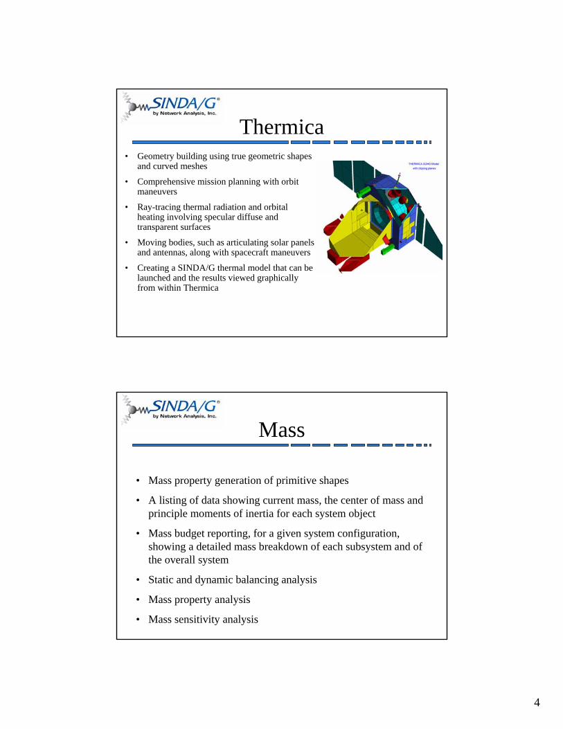
Thermica• Geometry building using true geometric shapes
and curved meshes
• Comprehensive mission planning with orbit maneuvers
• Ray-tracing thermal radiation and orbital heating involving specular diffuse and transparent surfaces
• Moving bodies, such as articulating solar panels and antennas, along with spacecraft maneuvers
• Creating a SINDA/G thermal model that can be launched and the results viewed graphically from within Thermica
Mass
• Mass property generation of primitive shapes
• A listing of data showing current mass, the center of mass and principle moments of inertia for each system object
• Mass budget reporting, for a given system configuration, showing a detailed mass breakdown of each subsystem and of the overall system
• Static and dynamic balancing analysis
• Mass property analysis
• Mass sensitivity analysis
5
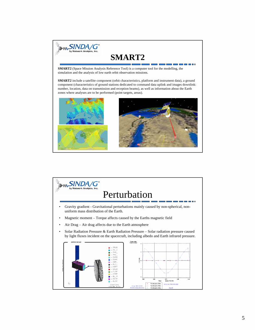
SMART2SMART2 (Space Mission Analysis Reference Tool) is a computer tool for the modelling, the simulation and the analysis of low earth orbit observation missions.
SMART2 include a satellite component (orbit characteristics, platform and instrument data), a ground component (characteristics of ground stations dedicated to command data uplink and images downlink: number, location, data on transmission and reception beams), as well as information about the Earth zones where analyses are to be performed (point targets, areas).
Perturbation• Gravity gradient - Gravitational perturbations mainly caused by non-spherical, non-
uniform mass distribution of the Earth.
• Magnetic moment – Torque affects caused by the Earths magnetic field
• Air Drag – Air drag affects due to the Earth atmosphere
• Solar Radiation Pressure & Earth Radiation Pressure – Solar radiation pressure caused by light fluxes incident on the spacecraft, including albedo and Earth infrared pressure.
6
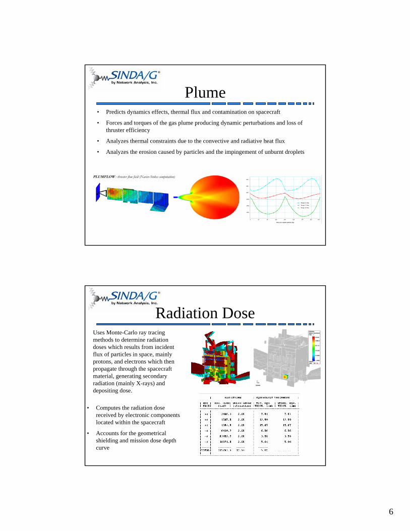
Plume• Predicts dynamics effects, thermal flux and contamination on spacecraft
• Forces and torques of the gas plume producing dynamic perturbations and loss of thruster efficiency
• Analyzes thermal constraints due to the convective and radiative heat flux
• Analyzes the erosion caused by particles and the impingement of unburnt droplets
PLUMFLOW : thruster flow field (Navier-Stokes computation)
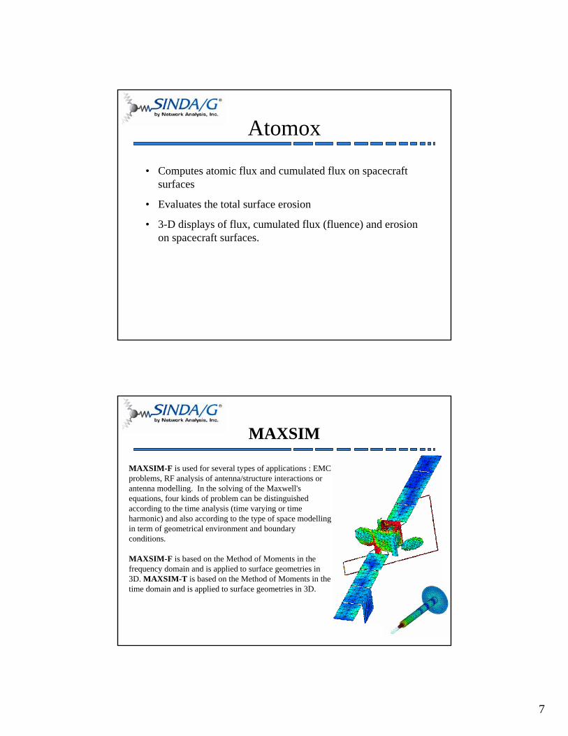
Radiation Dose
• Computes the radiation dose received by electronic components located within the spacecraft
• Accounts for the geometrical shielding and mission dose depth curve
Uses Monte-Carlo ray tracing methods to determine radiation doses which results from incident flux of particles in space, mainly protons, and electrons which then propagate through the spacecraft material, generating secondary radiation (mainly X-rays) and depositing dose.
7
Atomox
• Computes atomic flux and cumulated flux on spacecraft surfaces
• Evaluates the total surface erosion
• 3-D displays of flux, cumulated flux (fluence) and erosion on spacecraft surfaces.
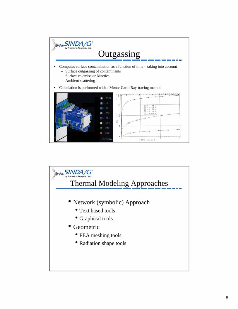
MAXSIM
MAXSIM-F is used for several types of applications : EMC problems, RF analysis of antenna/structure interactions or antenna modelling. In the solving of the Maxwell's equations, four kinds of problem can be distinguished according to the time analysis (time varying or time harmonic) and also according to the type of space modelling in term of geometrical environment and boundary conditions.
MAXSIM-F is based on the Method of Moments in the frequency domain and is applied to surface geometries in 3D. MAXSIM-T is based on the Method of Moments in the time domain and is applied to surface geometries in 3D.
8
Outgassing• Computes surface contamination as a function of time – taking into account
– Surface outgassing of contaminants– Surface re-emission kinetics– Ambient scattering
• Calculation is performed with a Monte-Carlo Ray-tracing method
Thermal Modeling Approaches
• Network (symbolic) Approach• Text based tools• Graphical tools
• Geometric • FEA meshing tools• Radiation shape tools
9
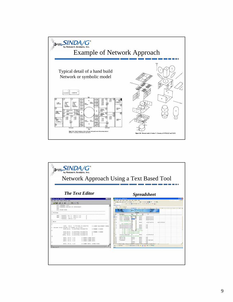
Example of Network Approach
Typical detail of a hand buildNetwork or symbolic model
Network Approach Using a Text Based Tool
The Text Editor Spreadsheet
10
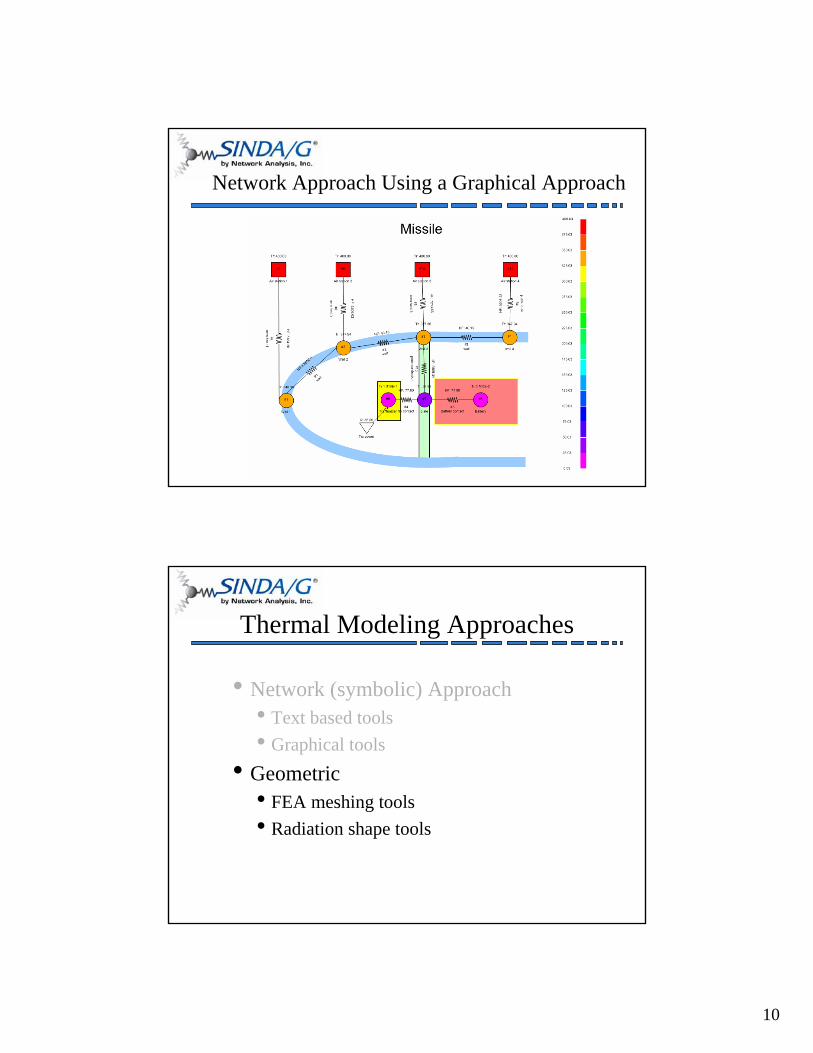
Network Approach Using a Graphical Approach
Thermal Modeling Approaches
• Network (symbolic) Approach• Text based tools• Graphical tools
• Geometric • FEA meshing tools• Radiation shape tools
11
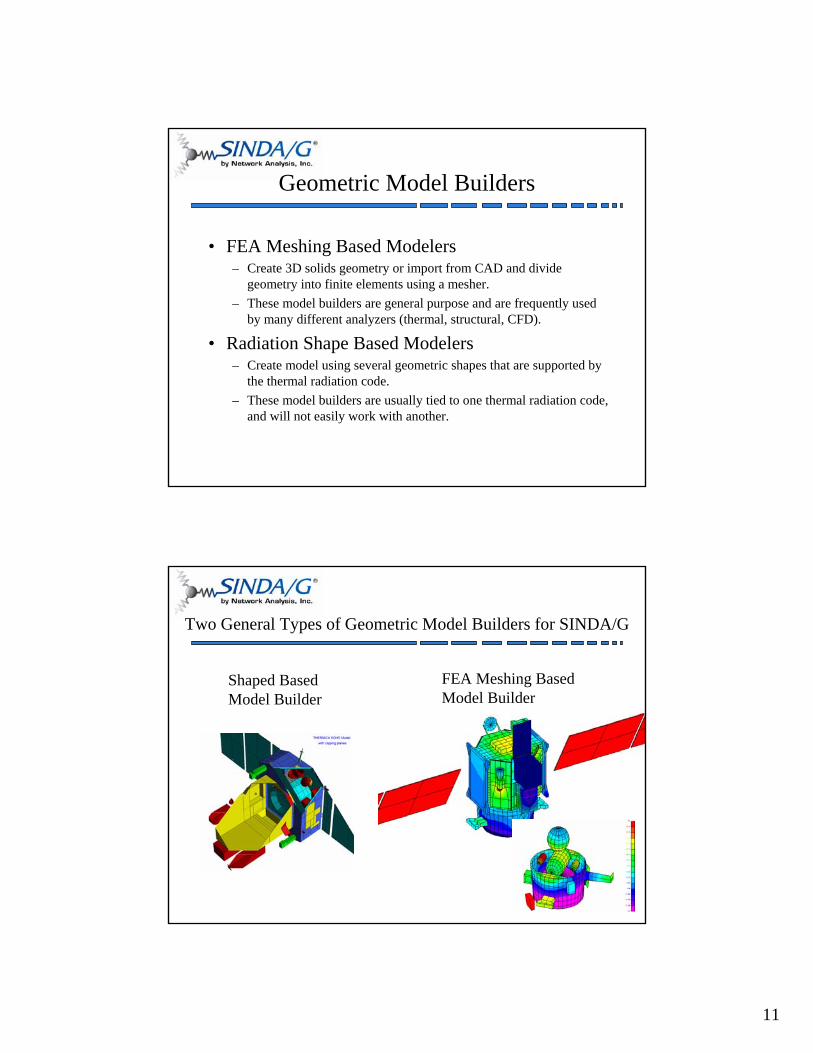
Geometric Model Builders
• FEA Meshing Based Modelers– Create 3D solids geometry or import from CAD and divide
geometry into finite elements using a mesher.– These model builders are general purpose and are frequently used
by many different analyzers (thermal, structural, CFD).
• Radiation Shape Based Modelers– Create model using several geometric shapes that are supported by
the thermal radiation code.– These model builders are usually tied to one thermal radiation code,
and will not easily work with another.
Two General Types of Geometric Model Builders for SINDA/G
Shaped Based Model Builder
FEA Meshing Based Model Builder
12
23
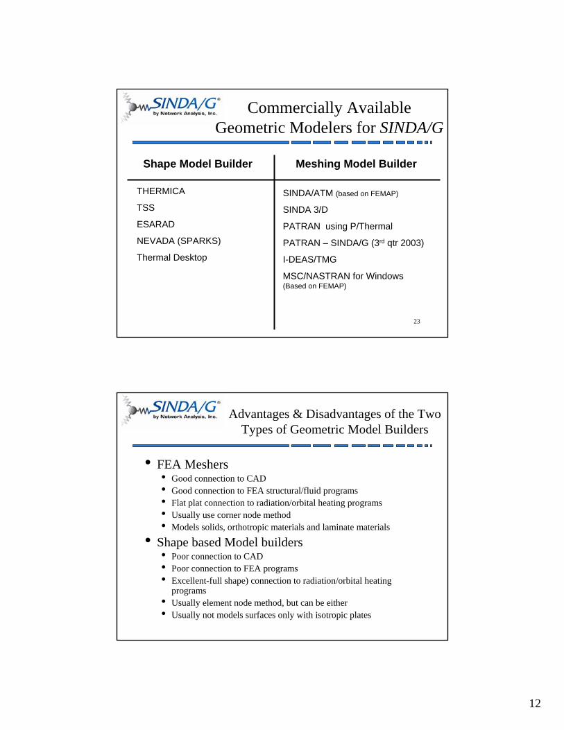
Commercially Available Geometric Modelers for SINDA/G
Shape Model Builder Meshing Model Builder
THERMICA
TSS
ESARAD
NEVADA (SPARKS)
Thermal Desktop
SINDA/ATM (based on FEMAP)
SINDA 3/D
PATRAN using P/Thermal
PATRAN – SINDA/G (3rd qtr 2003)
I-DEAS/TMG
MSC/NASTRAN for Windows(Based on FEMAP)
Advantages & Disadvantages of the Two Types of Geometric Model Builders
• FEA Meshers• Good connection to CAD• Good connection to FEA structural/fluid programs• Flat plat connection to radiation/orbital heating programs• Usually use corner node method• Models solids, orthotropic materials and laminate materials
• Shape based Model builders• Poor connection to CAD • Poor connection to FEA programs• Excellent-full shape) connection to radiation/orbital heating
programs• Usually element node method, but can be either• Usually not models surfaces only with isotropic plates
13
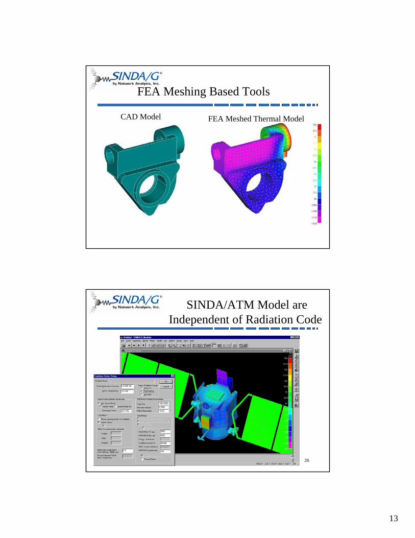
FEA Meshing Based Tools
CAD Model FEA Meshed Thermal Model
26
SINDA/ATM Model areIndependent of Radiation Code

14
Radiation Surfaces Created by Graphical Modelers
Hydrazine Tank Modeled with112 Flat Plates
Produces 6000+ radiation conductors
Hydrazine Tank Modeled with4 True Geometric Surfaces
Produces 6 radiation conductors
FEA MesherSINDA/3D
Shaped Based Modeler(THERMICA)
(end disk removed)
Typical Detail Level of Thermal Model
SPOT 4 GOMOS
SOHO
Hispasat

15
•SOHO Spacecraft
THERMICA-SINDA/G
•MMS Telecom Spacecraft
THERMICA-SINDA/G
16
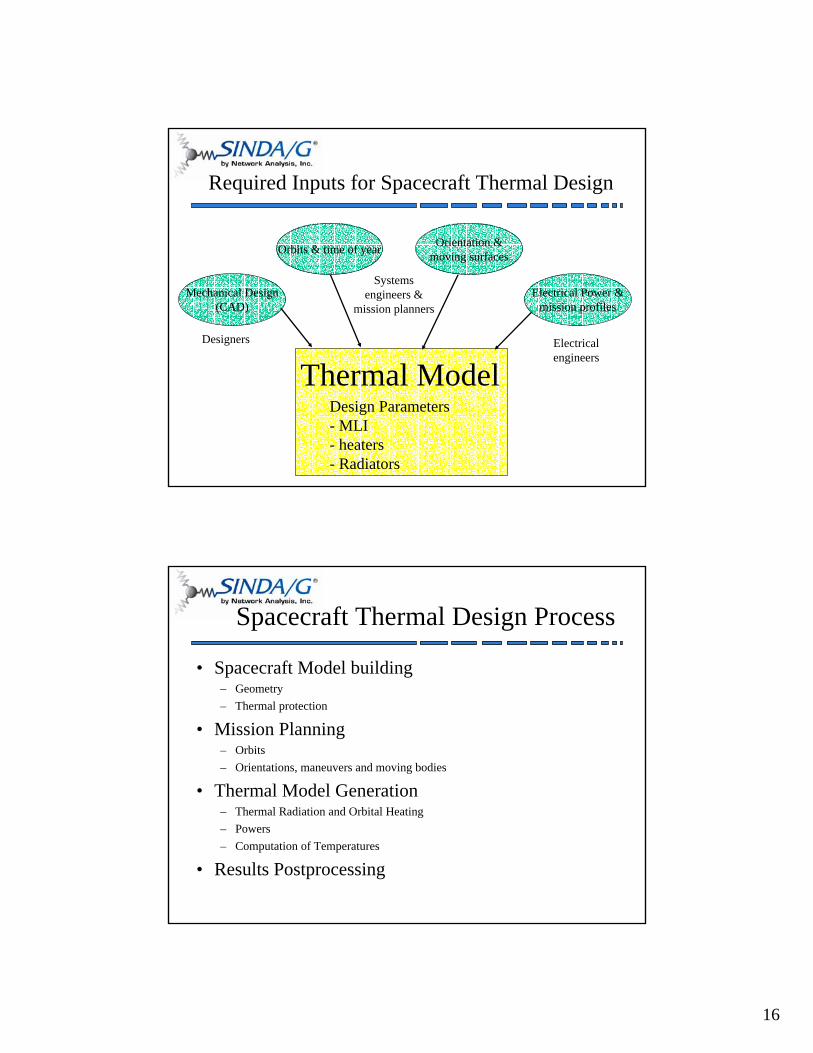
Required Inputs for Spacecraft Thermal Design
Thermal ModelDesign Parameters- MLI- heaters- Radiators
Orientation &moving surfaces
Mechanical Design(CAD)
Designers
Orbits & time of year
Systems engineers &
mission plannersElectrical Power &
mission profiles
Electrical engineers
Spacecraft Thermal Design Process
• Spacecraft Model building – Geometry– Thermal protection
• Mission Planning– Orbits– Orientations, maneuvers and moving bodies
• Thermal Model Generation– Thermal Radiation and Orbital Heating– Powers– Computation of Temperatures
• Results Postprocessing
17
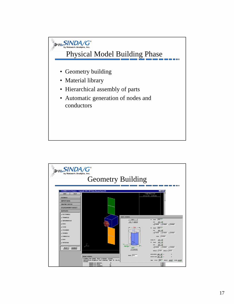
Physical Model Building Phase
• Geometry building • Material library• Hierarchical assembly of parts• Automatic generation of nodes and
conductors
Geometry Building
18
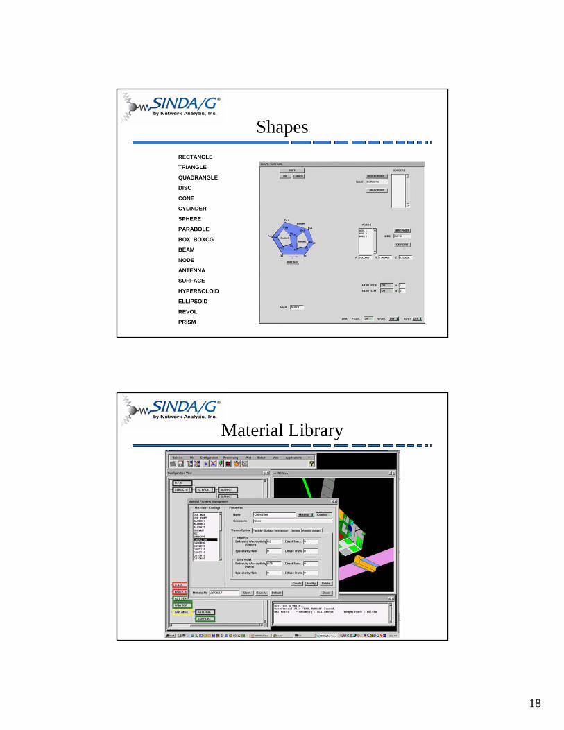
ShapesRECTANGLE
TRIANGLE
QUADRANGLE
DISC
CONE
CYLINDER
SPHERE
PARABOLE
BOX, BOXCG
BEAM
NODE
ANTENNA
SURFACE
HYPERBOLOID
ELLIPSOID
REVOL
PRISM
Material Library
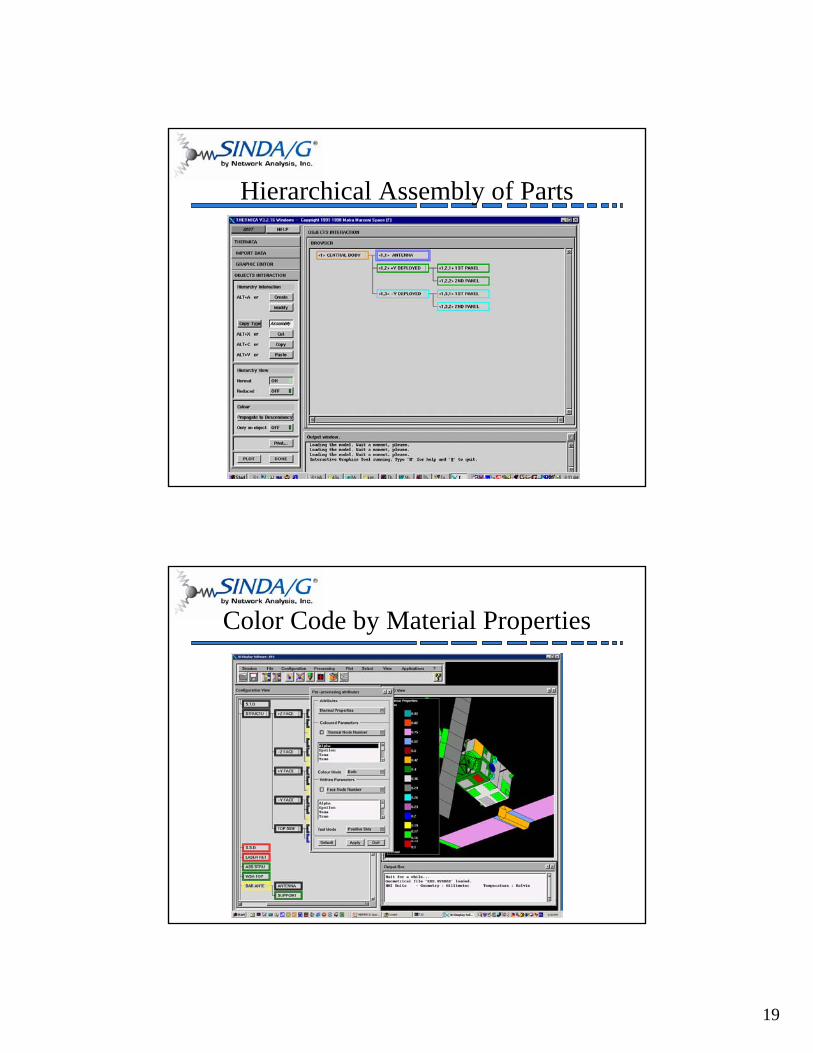
19
Hierarchical Assembly of Parts
Color Code by Material Properties
20
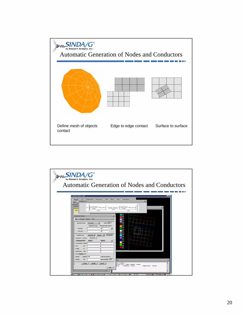
Automatic Generation of Nodes and Conductors
Define mesh of objects Edge to edge contact Surface to surface contact
Automatic Generation of Nodes and Conductors
21
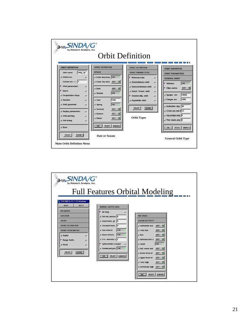
Orbit Definition
Main Orbit Definition Menu
Date or Season
Orbit Types
General Orbit Type
Full Features Orbital Modeling
22
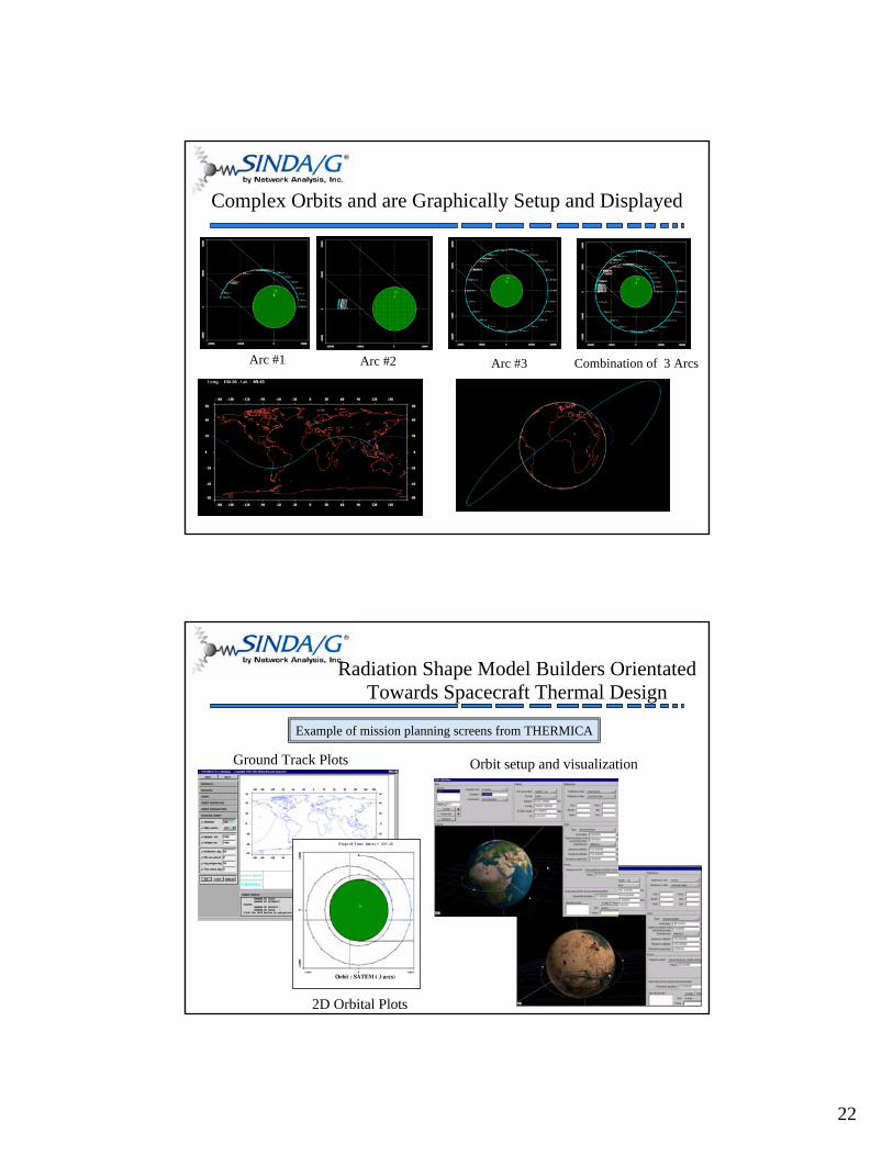
Complex Orbits and are Graphically Setup and Displayed
Arc #1 Arc #2 Arc #3 Combination of 3 Arcs
Radiation Shape Model Builders Orientated Towards Spacecraft Thermal Design
Ground Track Plots
2D Orbital Plots
Example of mission planning screens from THERMICA
Orbit setup and visualization
23
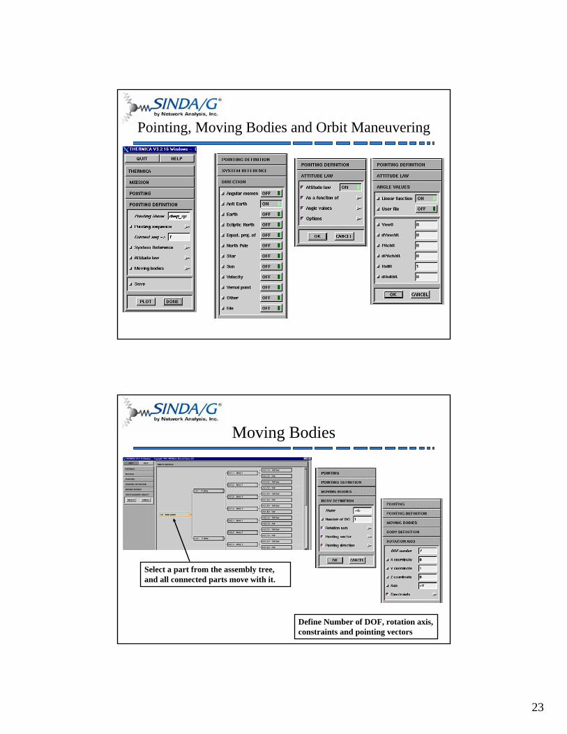
Pointing, Moving Bodies and Orbit Maneuvering
Moving Bodies
Define Number of DOF, rotation axis, constraints and pointing vectors
Select a part from the assembly tree, and all connected parts move with it.
24
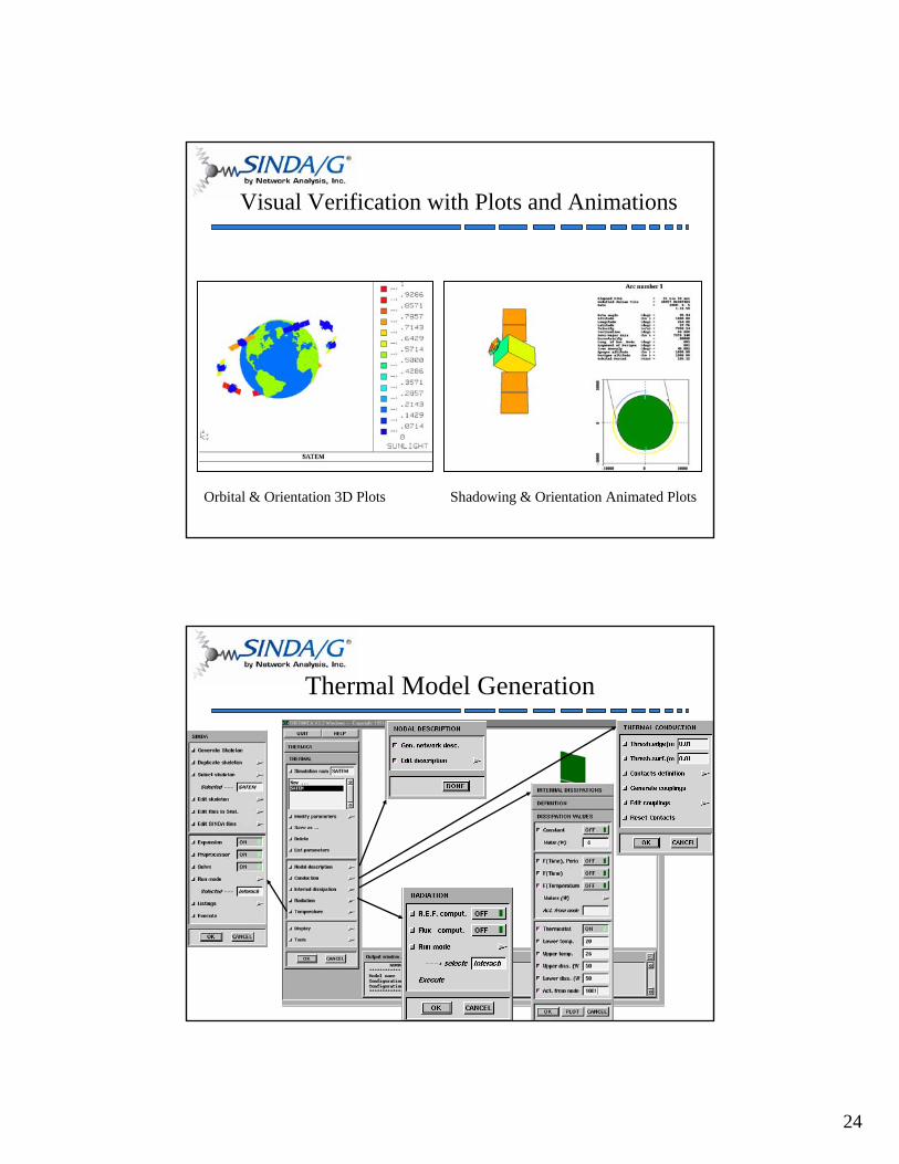
Visual Verification with Plots and Animations
Orbital & Orientation 3D Plots Shadowing & Orientation Animated Plots
Thermal Model Generation
25
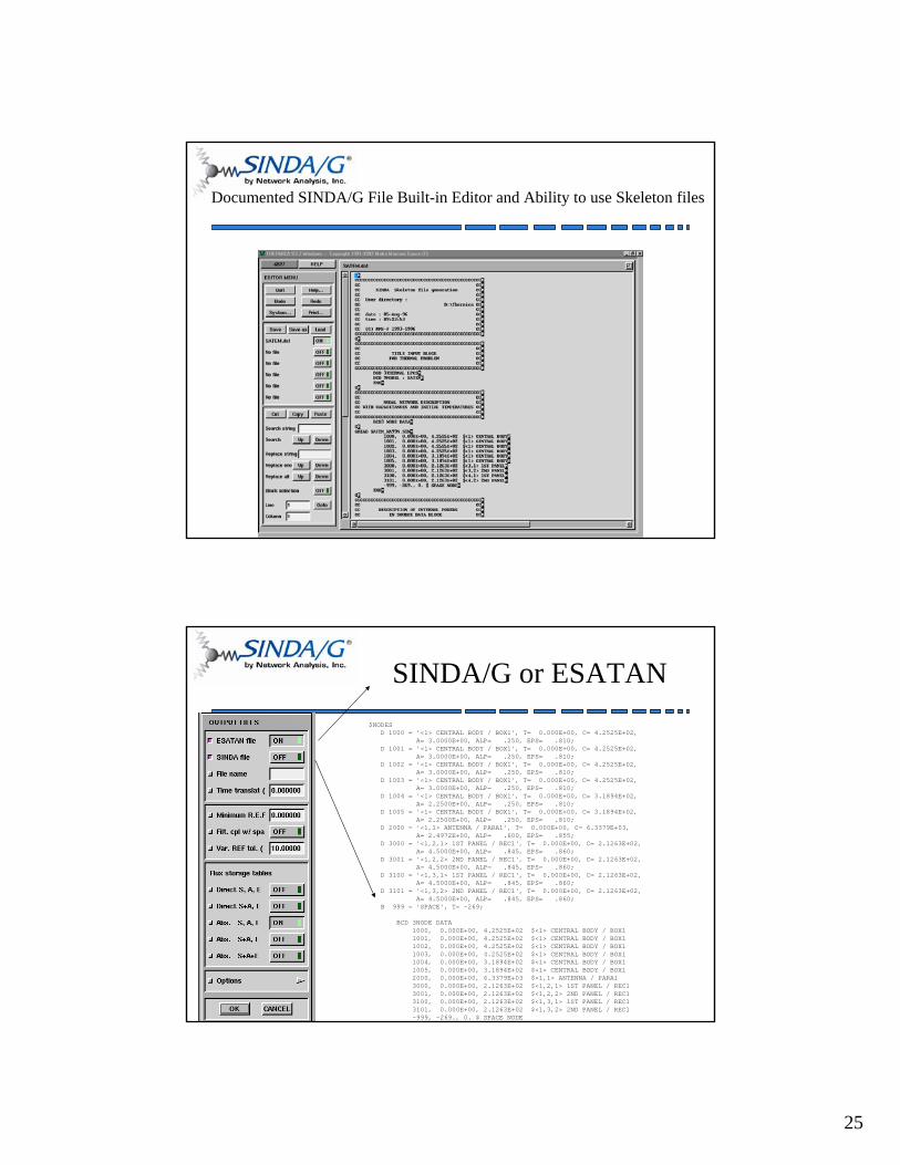
Documented SINDA/G File Built-in Editor and Ability to use Skeleton files
SINDA/G or ESATAN$NODES
D 1000 = '<1> CENTRAL BODY / BOX1', T= 0.000E+00, C= 4.2525E+02,A= 3.0000E+00, ALP= .250, EPS= .810;
D 1001 = '<1> CENTRAL BODY / BOX1', T= 0.000E+00, C= 4.2525E+02,A= 3.0000E+00, ALP= .250, EPS= .810;
D 1002 = '<1> CENTRAL BODY / BOX1', T= 0.000E+00, C= 4.2525E+02,A= 3.0000E+00, ALP= .250, EPS= .810;
D 1003 = '<1> CENTRAL BODY / BOX1', T= 0.000E+00, C= 4.2525E+02,A= 3.0000E+00, ALP= .250, EPS= .810;
D 1004 = '<1> CENTRAL BODY / BOX1', T= 0.000E+00, C= 3.1894E+02,A= 2.2500E+00, ALP= .250, EPS= .810;
D 1005 = '<1> CENTRAL BODY / BOX1', T= 0.000E+00, C= 3.1894E+02,A= 2.2500E+00, ALP= .250, EPS= .810;
D 2000 = '<1,1> ANTENNA / PARA1', T= 0.000E+00, C= 6.3379E+03,A= 2.4972E+00, ALP= .600, EPS= .855;
D 3000 = '<1,2,1> 1ST PANEL / REC1', T= 0.000E+00, C= 2.1263E+02,A= 4.5000E+00, ALP= .845, EPS= .860;
D 3001 = '<1,2,2> 2ND PANEL / REC1', T= 0.000E+00, C= 2.1263E+02,A= 4.5000E+00, ALP= .845, EPS= .860;
D 3100 = '<1,3,1> 1ST PANEL / REC1', T= 0.000E+00, C= 2.1263E+02,A= 4.5000E+00, ALP= .845, EPS= .860;
D 3101 = '<1,3,2> 2ND PANEL / REC1', T= 0.000E+00, C= 2.1263E+02,A= 4.5000E+00, ALP= .845, EPS= .860;
B 999 = 'SPACE', T= -269;
BCD 3NODE DATA1000, 0.000E+00, 4.2525E+02 $<1> CENTRAL BODY / BOX11001, 0.000E+00, 4.2525E+02 $<1> CENTRAL BODY / BOX11002, 0.000E+00, 4.2525E+02 $<1> CENTRAL BODY / BOX11003, 0.000E+00, 4.2525E+02 $<1> CENTRAL BODY / BOX11004, 0.000E+00, 3.1894E+02 $<1> CENTRAL BODY / BOX11005, 0.000E+00, 3.1894E+02 $<1> CENTRAL BODY / BOX12000, 0.000E+00, 6.3379E+03 $<1,1> ANTENNA / PARA13000, 0.000E+00, 2.1263E+02 $<1,2,1> 1ST PANEL / REC13001, 0.000E+00, 2.1263E+02 $<1,2,2> 2ND PANEL / REC13100, 0.000E+00, 2.1263E+02 $<1,3,1> 1ST PANEL / REC13101, 0.000E+00, 2.1263E+02 $<1,3,2> 2ND PANEL / REC1-999, -269., 0. $ SPACE NODE
26
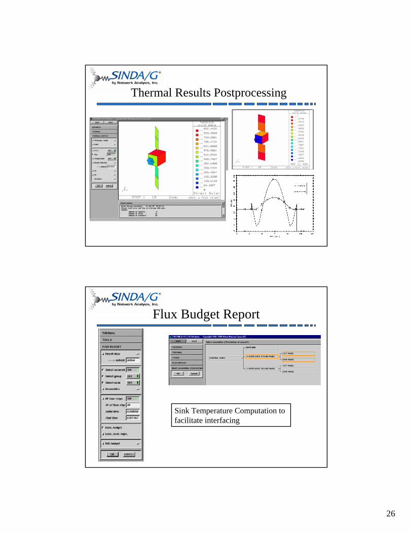
Thermal Results Postprocessing
Flux Budget Report
Sink Temperature Computation to facilitate interfacing
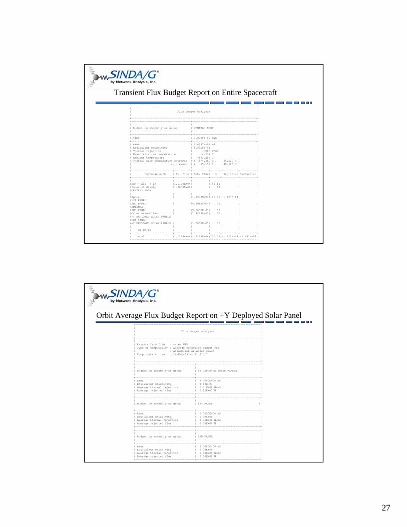
27
Transient Flux Budget Report on Entire Spacecraft +----------------------------------------------------------------------------+| || Flux budget analysis || |+----------------------------------------------------------------------------+ +------------------------------------+---------------------------------------+| | || Budget on assembly or group | CENTRAL BODY| | |+------------------------------------+---------------------------------------+| Time | 0.0000E+00 min |+------------------------------------+---------------------------------------+| Area | 3.4597E+01 m2 || Equivalent emissivity | 8.8955E-01 || Thermal rejection | .0000 W/m2 || Mean radiative temperature | 14.214 C || Ambient temperature | -133.255 C || Thermal node temperature extremes | [ -174.352 C , 86.520 C ] || at present | [ -65.152 C , 48.688 C ] || | |+-------------------------+----------+----------+------+----------+----------+| Exchange with | In. flux | Out. flux| % | Radiation|Conduction|+-------------------------+----------+----------+------+----------+----------+| | | | | | ||Sun + Alb. + IR |1.1128E+04| | 99.11| | ||Internal dissip. |1.0000E+02| | .89| | ||CENTRAL BODY| | | | | | ||Space | |1.1228E+04|100.00|-1.123E+04| ||1ST PANEL|2ND PANEL | |5.1962E-01| .00| | ||ANTENNA|2ND PANEL | |5.0000E-01| .00| | ||Other assemblies | |2.4245E-01| .00| | ||-Y DEPLOYED SOLAR PANELS|1ST PANEL|+Y DEPLOYED SOLAR PANELS | |1.0000E-01| .00| | || | | | | | || -Cp.dT/dt | | | | | |+-------------------------+----------+----------+------+----------+----------+| Total |1.1228E+04|1.1228E+04|100.00|-1.123E+04|-2.682E-07|+-------------------------+----------+----------+------+----------+----------+
Orbit Average Flux Budget Report on +Y Deployed Solar Panel +----------------------------------------------------------------------------+| || Flux budget analysis || |+----------------------------------------------------------------------------+| || Results from file : satem.NTP || Type of computation : Average rejection budget for || : assemblies or nodes group || Comp. date & time : 24-Feb-99 at 11:21:17 || |+----------------------------------------------------------------------------++------------------------------------+---------------------------------------+| | || Budget on assembly or group | +Y DEPLOYED SOLAR PANELS || | |+------------------------------------+---------------------------------------+| Area | 9.0000E+00 m2 || Equivalent emissivity | 8.63E-01 || Average thermal rejection | 6.91E+00 W/m2 || Average rejected flux | 6.22E+01 W |+------------------------------------+---------------------------------------++------------------------------------+---------------------------------------+| | || Budget on assembly or group | 1ST PANEL |
|+------------------------------------+---------------------------------------+| Area | 0.0000E+00 m2 || Equivalent emissivity | 0.00E+00 || Average thermal rejection | 0.00E+00 W/m2 || Average rejected flux | 0.00E+00 W |+------------------------------------+---------------------------------------++------------------------------------+---------------------------------------+| | || Budget on assembly or group | 2ND PANEL || | |+------------------------------------+---------------------------------------+| Area | 0.0000E+00 m2 || Equivalent emissivity | 0.00E+00 || Average thermal rejection | 0.00E+00 W/m2 || Average rejected flux | 0.00E+00 W |+------------------------------------+---------------------------------------+
28
THERMICA User Experience
Lessons Learned
Lessons Learned by Major Spacecraft Company
• Five to Ten Times More Product Produced (time wise) -Compared to other tools that were previously used
• Multi-discipline Design Support – provides insight on CONOPS, Star Tracker Viewing, Solar Collection
• Very Responsive To Proposal Activities
• Set New Standards For Quality & Timeliness
• Fifteen Major Satellite Programs Supported in Last 18 Months. (Teledesic, Ellipso, @Contact, Discoverer II, ReFly, GPS II F, Mars Sample Return, GE*, etc.)
• Easy to learn – requires no formal training budget
• Runs on a PC – eliminates costly Unix workstations

29
Successful Use of THERMICA at a Major Aerospace Company
• A user friendly interface and easy to use geometry model building tools allow for rapid design concept model generation
• This permits thermal considerations to have an impact on the system design, mission planning and the concept of operations
• Key trades are also performed early on to produce a more optimal design
• THERMICA was used successfully on 14 different programs in the last two years and 4 major contracts were awarded as a result
• All this was accomplished by two analyst, demonstrating a productivity increase of more than 5 times greater than previously experienced
THERMICA Permits Rapid Generation of Complex Thermal Models
Mars Sample Return Mission
Orbiter
Ascent Vehicle Lander & Ascent Vehicle
GPS MOD
Teledesic
GE Star
X-37
These Models were built in 3 to 5 Days
30
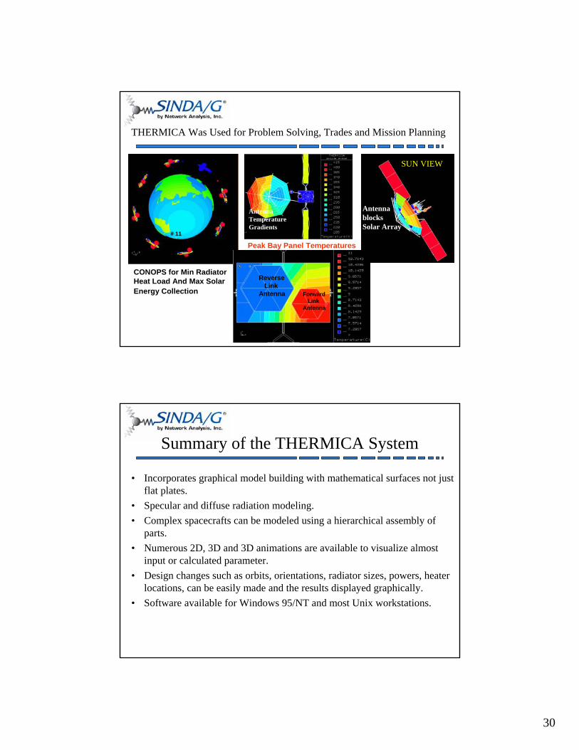
THERMICA Was Used for Problem Solving, Trades and Mission Planning
SUN VIEW
Antennablocks Solar Array
CONOPS for Min Radiator Heat Load And Max SolarEnergy Collection
Peak Bay Panel Temperatures# 11
ReverseLink
Antenna ForwardLink
Antenna
AntennaTemperatureGradients
Summary of the THERMICA System
• Incorporates graphical model building with mathematical surfaces not just flat plates.
• Specular and diffuse radiation modeling.• Complex spacecrafts can be modeled using a hierarchical assembly of
parts.• Numerous 2D, 3D and 3D animations are available to visualize almost
input or calculated parameter.• Design changes such as orbits, orientations, radiator sizes, powers, heater
locations, can be easily made and the results displayed graphically.• Software available for Windows 95/NT and most Unix workstations.