Embed Size (px)
Citation preview
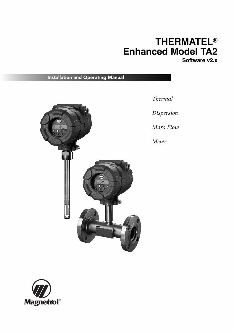
®
Thermal
Dispersion
Mass Flow
Meter
Installation and Operating Manual
THERMATEL®Enhanced Model TA2
Software v2.x
2
MOUNTING
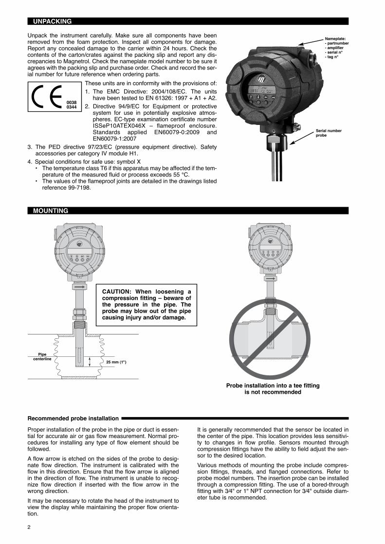
Nameplate:- partnumber- amplifier- serial n°- tag n°
Serial numberprobe
Recommended probe installation
Pipecenterline 25 mm (1")
CAUTION: When loosening acompression fitting – beware ofthe pressure in the pipe. Theprobe may blow out of the pipecausing injury and/or damage.
Probe installation into a tee fittingis not recommended
UNPACKING
Unpack the instrument carefully. Make sure all components have beenremoved from the foam protection. Inspect all components for damage.Report any concealed damage to the carrier within 24 hours. Check thecontents of the carton/crates against the packing slip and report any dis-crepancies to Magnetrol. Check the nameplate model number to be sure itagrees with the packing slip and purchase order. Check and record the ser-ial number for future reference when ordering parts.
Proper installation of the probe in the pipe or duct is essen-tial for accurate air or gas flow measurement. Normal pro-cedures for installing any type of flow element should befollowed.A flow arrow is etched on the sides of the probe to desig-nate flow direction. The instrument is calibrated with theflow in this direction. Ensure that the flow arrow is alignedin the direction of flow. The instrument is unable to recog-nize flow direction if inserted with the flow arrow in thewrong direction.It may be necessary to rotate the head of the instrument toview the display while maintaining the proper flow orienta-tion.
It is generally recommended that the sensor be located inthe center of the pipe. This location provides less sensitivi-ty to changes in flow profile. Sensors mounted throughcompression fittings have the ability to field adjust the sen-sor to the desired location.Various methods of mounting the probe include compres-sion fittings, threads, and flanged connections. Refer toprobe model numbers. The insertion probe can be installedthrough a compression fitting. The use of a bored-throughfitting with 3⁄4" or 1" NPT connection for 3⁄4" outside diam-eter tube is recommended.
These units are in conformity with the provisions of:1. The EMC Directive: 2004/108/EC. The units
have been tested to EN 61326: 1997 + A1 + A2.2. Directive 94/9/EC for Equipment or protective
system for use in potentially explosive atmos-pheres. EC-type examination certificate numberISSeP10ATEX046X – flameproof enclosure.Standards applied EN60079-0:2009 andEN60079-1:2007
3. The PED directive 97/23/EC (pressure equipment directive). Safetyaccessories per category IV module H1.
4. Special conditions for safe use: symbol X• The temperature class T6 if this apparatus may be affected if the tem-
perature of the measured fluid or process exceeds 55 °C.• The values of the flameproof joints are detailed in the drawings listed
reference 99-7198.
00380344

3
Flow profiles
NOTE: Do not install the probe in locations where con-densed moisture can be present. The unit may cause afalse high flow indication. In some cases heat tracing orinsulation of the pipe must be considered to avoidmoisture condensation.
Install the TA2 sensor at a 45° angle to minimize moisturedrip. Use of different TA2ʼs as shown is recommended tooptimize the accuracy in a larger pipe dia.
Gas flows around an elbow and creates a swirl
Install the TA2 further away, the flow profile will redevelop
Swirl patterns in a pipe Probe in a ductdownstream of elbow
TA2 installed in a large ductfor combustion air control: Probe
is located a short distance from a 90° bend,providing a repeatable flow measurement that
allows to optimize the operation of the boiler
Flow is “0”
Flow is 20 % higher thanaverage velocity, but isrelatively flat in profile
Ideal sensor locationis in centre of the pipe(= end of probe 25 mmbelow centerline)
Turbulent flow profile Flow profile following single elbow
Gas velocity on the outside of theelbow is higher
A double elbow furthercomplicates the flowprofile
Install the TA2 instraight run locations
45° 45°
45°45°
The use of Teflon® ferrules should be considered if repeat-ed reposition of the sensor is considered. The stainlesssteel ferrule can only be tightened once as it makes a per-manent indentation on the probe. If using a compression fit-ting with stainless steel ferrules, ensure that the probe is inthe desired location before tightening.The TA2 flow measurement is based on a fully developedturbulent flow profile in a pipe with the specified inner dia-meter. Accuracy will be affected if these conditions are notobtained. Installing the probe in a tee is not recommendedas the flow profile and the flow area are distorted.
For applications where it is desirable to install or removethe probe without having to shut down the process,Magnetrolʼs Retractable Probe Assembly (RPA) can be uti-lized.The TA2 with an insertion probe provides a point measure-ment and assumes that the velocity profile (see figuresbelow) is uniform over the entire width of the pipe or duct.The user has the ability to compensate the flow measure-ments based upon flow profile considerations under theAdvanced Configuration section of the software.

FLOW
FLOW
FLOW
FLOW
FLOW
FLOW
Ø x 50 Ø x 5
4
ø x 15 ø x 5 ø x 15 ø x 5
ø x 15 ø x 5ø x 20 ø x 5
ø x 35
Connects to J1 on the logic board
The TA2 has a plug in display(ordered with the unit or separately).
The display can be rotated in 90° increments.Remove both mounting screws and reposition
at desired position.
ø x 5
One 90° elbow
CAUTION: Switch power offwhen connecting/disconnectingthe display
Reduction
ExpansionTwo 90° elbows in plane
Two 90° elbows out of plane
Mounting recommendations
Display
Control Valve - It is recommended that control
valves be installed downstream of the flow meter

5
WIRING
Integral electronics
Remote electronics
CAUTION: In harzardous area, do NOT power the unit until the cable gland is sealed and the housingcover of the wiring compartment is screwed down securely / housing locking screw is fastened – dis-abling the removal of the cover.
Terminal boardon main
electronics
Ex Non Ex
Power supplyOutput
Shield to ground
8 or 10-wire shieldedcable – see MODELIDENTIFICATION
Remote probe wiringNOTE: Explosion proof cable is labelled as per terminal number
POWERLOOP2
OUTPUT
100-264 VAC
L1L2
DC INPUT
+- P- A+ P-
LOOP1/HARTOUTPUT
PULSE/
P+P-
50/ 60Hz
INPUTAC
A-P+ A-
P+ A+
ALARM
TB3D6TB4TB2
TB5
R1
F1
TB1
Power supply
Active or Passive output
OutputShield to ground
Optional pulse output: connect signal wiring to TB4 in combination with anactive or passive outputOptional second mA output: connect signal wiring to TB5, passive output.
Shielded twistedpair cable
Redesigned wiring connection
A- / A+ = active output: power supplied by TA2
P- / P+ = passive output: power supplied byexternal 24 V DC source
Ex Non Ex
POWERLOOP2
OUTPUT
100-264 VAC
L1L2
DC INPUT
+- P- A+ P-
LOOP1/HARTOUTPUT
PULSE/
P+P-
50/ 60Hz
INPUTAC
A-P+ A-
P+ A+
ALARM
TB3D6TB4TB2
TB5
R1
F1
TB1
TB1
TB2
J1
bro
wn
5 4 3 2 1
oran
ge
To Probe
blu
eb
lack
whi
te
1 2 3 4 5 6 7 8 910
1 2 3 4 5 6 7 8 910 11
Remote wiring cable connections1. Green/White2. White/Green3. Blue/White4. White/Blue5. Brown/White6. White/Brown7. Orange/White8. White/Orange9.
10.11. Shield

6
PASSWORD
CONFIGURATION
IMPORTANT: TA2 units are pre-configured from factory (as per order specifications). Only modify con-figuration settings in case needed.
NOTE: When power is first applied to the TA2 there is an initialization period for the sensor to reach stabilization.During this time the TA2 will output a 4 mA signal and the display (if provided) will read «Initializing TA2». Only after thesensor has stabilized and a valid flow measurement is obtained will the display show a flow measurement, the outputsignal will be active and the totalizer will begin counting.
2 line - 16 characters LCD.Default display cycles every 1,5 s throughFLOW / MASS / TEMPERATURE / TOTALIZED FLOW / mA OUTPUT
UP / DOWN / DELETE and ENTER pushbuttons
Keys Comment(Up) Scroll to the previous selection/menu in the list or
increase a value (behind decimal/negative values show “-”) orscroll forward through graphical characters or digits.If held down; the characters scroll until the pushbutton is released.
(Down) Scroll to the next selection/menu in the list ordecrease a value (behind decimal/negative values show “-”) orscroll backward through graphical characters.If held down; the characters scroll until the pushbutton is released.
(Delete) Moves back one level to the previous higher branch or menu level without changes ormoves the cursor to the left to delete an entry.
(Enter) Enters into the lower level branch.Accepts the selection and returns to the menu traversal mode.Moves the cursor to the right to quit/save a selection (cursor must be in a blank position).
Access MenuWhen attempting to enter a selection setting, the unit will display:
Display Item Action«Usr Passwd Req’d»«Prb Passwd Req’d»
User password requiredProbe password required*
Unit shows an encrypted value. Enter“0” (factory default password or anymodified user password (001 - 255))
* only needed when original probe was replaced – factory default is “0”
Select a new PasswordMove to «Adv Config» menu-selection
Display Item Action
«Change Password»to select Change password
Enter old password «Enter old password»Enter new password «Enter new pass-word» (any value between 001 - 255)
Add new Password for probe replacementMove to «Factory Config» menu-selection
Password forgotten/lost – consult factory for assistance, your password can be recooped via the encrypted value displayedwhen the Password is asked for (see Access Menu).
Display Item Action«Probe Params»
to select Probe parameters Scroll through entries (factors are pro-vided with the new probe)

7
CONFIGURATION
Measured Values
Flow Area
Home
AO1 Loop Config
AO2 Loop Config
HistoryDiagnostics
Factory Config
Basic Config
I/O Config
Advanced Config Totalizers
Signal Value
Secondary loop, TransistorOutput and HART®
configuration are optional
TA2 User InterfaceMenu Hierarchy Overview
Device Info
Main MenuThe main menu is used to access the various subroutines. From the Run mode, press any key to enter the Main Menu. Thefollowing chart defines the various selections available.
Display Item Action if is pressed
«Measured Values» Measured values Enter Measured Values menu
«Basic Config» System configuration Enter System Configuration menu
«I/O Config» I/O configuration Enter Input/Output Configuration menu
«Adv Config» Advanced configuration Enter Advanced Configuration menu
«Device Info» Device information Enter Device Information menu
«Diagnostics» Diagnostics Enter Diagnostic menu
«Factory Config» Factory configuration Enter Factory Configuration menu
8
CONFIGURATION
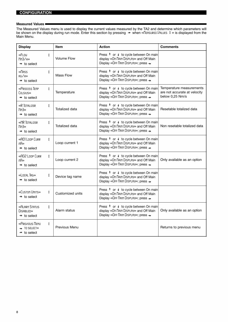
Measured ValuesThe Measured Values menu is used to display the current values measured by the TA2 and determine which parameters willbe shown on the display during run mode. Enter this section by pressing when «Measured Values » is displayed from theMain Menu.
Display Item Action Comments
«FlowNm3/h»
to selectVolume Flow
Press or to cycle between On maindisplay «On Main Display» and Off MainDisplay «Off Main Display»; press
«Masskg/h»
to selectMass Flow
Press or to cycle between On maindisplay «On Main Display» and Off MainDisplay «Off Main Display»; press
«Process TempCelsius»
to selectTemperature
Press or to cycle between On maindisplay «On Main Display» and Off MainDisplay «Off Main Display»; press
Temperature measurementsare not accurate at velocitybelow 0,25 Nm/s
«R TotalizerNm3»
to selectTotalized data
Press or to cycle between On maindisplay «On Main Display» and Off MainDisplay «Off Main Display»; press
Resetable totalized data
«NR TotalizerNm3»
to selectTotalized data
Press or to cycle between On maindisplay «On Main Display» and Off MainDisplay «Off Main Display»; press
Non resetable totalized data
«A01 Loop CurrmA»
to selectLoop current 1
Press or to cycle between On maindisplay «On Main Display» and Off MainDisplay «Off Main Display»; press
«A02 Loop CurrmA»
to selectLoop current 2
Press or to cycle between On maindisplay «On Main Display» and Off MainDisplay «Off Main Display»; press
Only available as an option
«Local Tag»to select
Device tag namePress or to cycle between On maindisplay «On Main Display» and Off MainDisplay «Off Main Display»; press
«Custom Units»to select
Customized unitsPress or to cycle between On maindisplay «On Main Display» and Off MainDisplay «Off Main Display»; press
«Alarm StatusDisabled»
to selectAlarm status
Press or to cycle between On maindisplay «On Main Display» and Off MainDisplay «Off Main Display»; press
Only available as an option
«Previous Menuto select»to select
Previous Menu Returns to previous menu

9
CONFIGURATION
* [label] *[string or value]
Model TA2 [HT, NP]Ver 2.0 a0
* Status *[fault or warning]
Measured Valuesto select
Basic Configto select
I/O Configto select
Advanced Configto select
Device Infoto select
Diagnosticsto select
Factory Configto select
Flownnn units
On Main DispOff Main Disp
Process Tempnnn units
Massnnn units
R Totalizernnnn units
NR Totalizernnnn units
A01 Loop Currnn.nn mA
A02 Loop Currnn.nn mA
Local TagMagnetrol TA2
Custom Unitsnnnn units
Alarm Statusnnnn units
Secondary loopand alarm are
only available on unitswhich have these options(Model TA2-A4XX-XXX).
TA2 User InterfaceHome and Associated Menus
DEL
DEL
DEL
DEL
DEL
DEL
UPDN
UPDN UP
DN
UPDN
UPDN
UPDN
UPDN
UPDN
UPDN
UPDN
UPDN
UPDN
UPDN
UPDN
UPDN
UPDN
UPDN
UPDN
DEL
UPDN
UPDN
DEL
DEL
DEL
DEL
DEL
DEL
DEL
DEL
DEL
ENTDEL
UPDNENTDEL
Shown only if fault or warning
Rotating screens
start
ENT
ENT
ENT
ENT
ENT
ENT
ENT
ENT
ENT
ENT
ENT
Previous Menuto select
10
CONFIGURATION
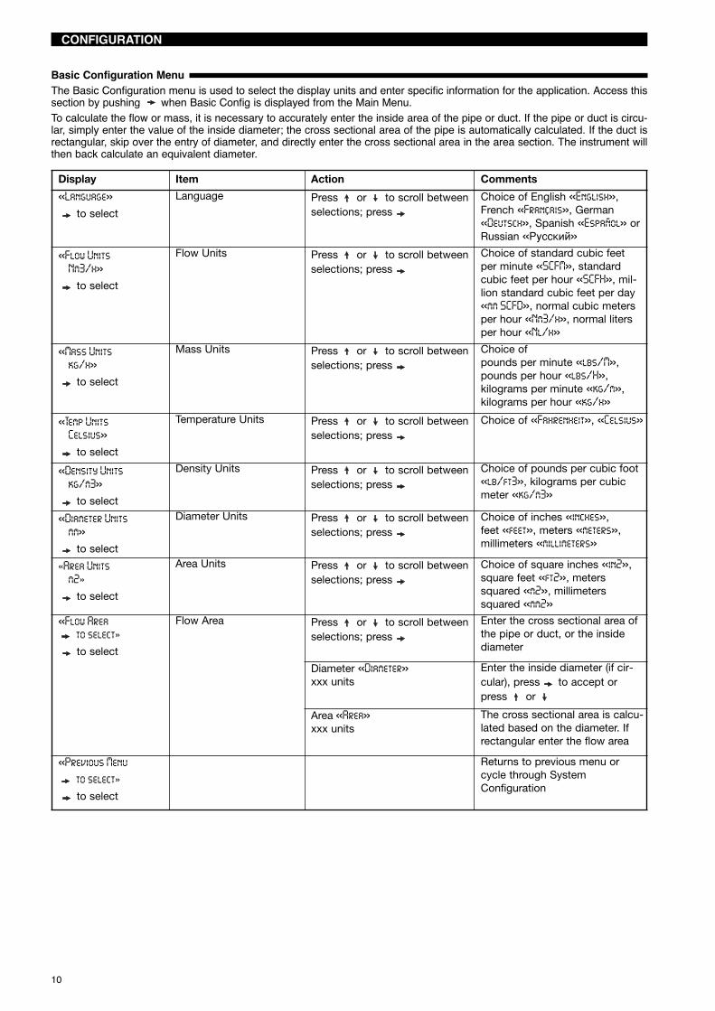
Basic Configuration MenuThe Basic Configuration menu is used to select the display units and enter specific information for the application. Access thissection by pushing when Basic Config is displayed from the Main Menu.To calculate the flow or mass, it is necessary to accurately enter the inside area of the pipe or duct. If the pipe or duct is circu-lar, simply enter the value of the inside diameter; the cross sectional area of the pipe is automatically calculated. If the duct isrectangular, skip over the entry of diameter, and directly enter the cross sectional area in the area section. The instrument willthen back calculate an equivalent diameter.
Display Item Action Comments
«Language»to select
Language Press or to scroll betweenselections; press
Choice of English «English»,French «Français», German«Deutsch», Spanish «Español» orRussian «Русский»
«Flow UnitsNm3/h»to select
Flow Units Press or to scroll betweenselections; press
Choice of standard cubic feetper minute «SCFM», standardcubic feet per hour «SCFH», mil-lion standard cubic feet per day«mm SCFD», normal cubic metersper hour «Nm3/h», normal litersper hour «Nl/h»
«Mass Unitskg/h»to select
Mass Units Press or to scroll betweenselections; press
Choice ofpounds per minute «lbs/M»,pounds per hour «lbs/H»,kilograms per minute «kg/m»,kilograms per hour «kg/h»
«Temp UnitsCelsius»to select
Temperature Units Press or to scroll betweenselections; press
Choice of «Fahrenheit», «Celsius»
«Density Unitskg/m3»to select
Density Units Press or to scroll betweenselections; press
Choice of pounds per cubic foot«lb/ft3», kilograms per cubicmeter «kg/m3»
«Diameter Unitsmm»to select
Diameter Units Press or to scroll betweenselections; press
Choice of inches «inches»,feet «feet», meters «meters»,millimeters «millimeters»
«Area Unitsm2»to select
Area Units Press or to scroll betweenselections; press
Choice of square inches «in2»,square feet «ft2», meterssquared «m2», millimeterssquared «mm2»
«Flow Areato select»to select
Flow Area Press or to scroll betweenselections; press
Enter the cross sectional area ofthe pipe or duct, or the insidediameter
Diameter «Diameter»xxx units
Enter the inside diameter (if cir-cular), press to accept orpress or
Area «Area»xxx units
The cross sectional area is calcu-lated based on the diameter. Ifrectangular enter the flow area
«Previous Menuto select»to select
Returns to previous menu orcycle through SystemConfiguration

11
CONFIGURATION
Basic Config–> to select
Language[selection]
Flow Units[selection]
Mass Units[selection]
Temp Units[selection]
Density Units[selection]
Diameter Units[selection]
Area Units[selection]
Flow Areato select
lb/Hlb/Mkg/hkg/m
TA2 User InterfaceSystem Configuration Menu
SCFMSCFH
MM SCFDNm3/h
Nl/h
EnglishFrancaisDeutschEspañolРуссКий
FahrenheitCelsius
lb/ft3kg/m3
inchesfeet
metersmillimeters
in2ft2m2
mm2
decimal entryin selected units
decimal entryin selected units
DEL
DEL
DEL
DEL
DEL
DEL
DEL
DEL
ENTDEL
UPDN
UPDN
UPDN
UPDN
UPDN
UPDN
UPDN
UPDN
UPDN
ENTDEL
ENTDEL
ENTDEL
ENTDEL
ENTDEL
ENTDEL
Pipe ID[selection]
Area[selection]
UPDN
ENTDEL
ENTDEL
ENTDEL
ENTDEL
Previous Menuto select

12
CONFIGURATION
I/O Configuration MenuThe I/O Configuration menu is used to set up the operations of 4–20 mA output, the totalizer, and the pulse/alarm output.Access this section by pushing when «I/O Config» is displayed.
4-20 mATo access the 4-20 mA signal, scroll or until the display shows «A01 Loop», press .
Display Item Action Comments«Loop Control Flow»
to selectControlled by flow Press or to cycle between
optionsChoice is Flow «Flow»or Mass «Mass»
«LRV (4 mA) Setxxxxx units»
to select
4 mA set pointxxxxx units
Set mA point using keypad Enter value for 4 mA point. Unitsare based upon selection «LoopControl»
«URV (20 mA) Setxxxx units»
to select
20 mA set pointxxxxx units
Set mA point using keypad Enter value for 20 mA point
«Fault State xx mA»to select
Fault modexx mA
Press or to cycle between«22 mA», «3.6 mA» or «Hold»
Select status of 4-20 mA loop inevent of fault
«Previous Menuto select»to select
Previous menu Returns to previous menu
Display Item Action Comments«Loop Control Flow»
to selectControlled by flow Press or to cycle between
optionsChoice is Flow «Flow», Mass«Mass» or Process Temperature«Process Temp»
«LRV (4 mA) Setxxxxx units»
to select
4 mA set pointxxxxx units
Set mA point using keypad Enter value for 4 mA point. Unitsare based upon selection «LoopControl»
«URV (20 mA) Setxxxx units»
to select
20 mA set pointxxxxx units
Set mA point using keypad Enter value for 20 mA point
«Previous Menuto select»to select
Previous menu Returns to previous menu
4-20 mA, Optional loopTo access the 4-20 mA signal, scroll or until the display shows «A02 Loop», press .

13
CONFIGURATION
A01 Loop Configto select
I/O Configto select
A02 Loop Configto select
Totalizersto select
Transistor Outto select
Damping (0 –15)[entered value]
Loop Control[selection]
LRV (4 mA) Set[entered value]
URV (20 mA) Set[entered value]
Fault State[selection]
Previous Menuto select
Loop Control[selection]
LRV (4 mA) Set[entered value]
URV (20 mA) Set[entered value]
FlowMass
Transistor Outputconfiguration is
only available on unitswhich have this option.
Secondary loopconfiguration is
only available on unitswhich have this option.
TA2 User InterfaceI/O Configuration Menu
DEL
DEL
DEL
DEL
DEL
DEL
DEL
DEL
DEL
DEL
ENTDEL
UPDN
UPDN
UPDN
UPDN
UPDN
UPDN
UPDN
UPDN
UPDN
UPDN
UPDN
UPDN
UPDN
UPDN
UPDN
UPDN
UPDN
decimal entryin selected
units
decimal entryin selected
units
decimal entryin selected
units
decimal entryin selected
units
ENTDEL
22 mA3.6 mAHold
ENTDEL
[inc/dec]0–15
ENTDEL
FlowMass
Process Temp
ENTDEL
ENTDEL
ENTDEL
ENTDEL
ENTDEL
ENTDEL
ENTDEL
ENTDEL
ENTDEL
see page 14-15for Totalizer
Configuration
see page 16-17 forTransistor Output
Configuration
Previous Menuto select
Previous Menuto select

14
TotalizerThe totalizer maintains a continuous, running total of the flow in selectable units. It also provides elapsed time since the lasttotalizer reset. The totalizer utilises eeprom memory, eliminating the need for a battery backup. The totalizer can be reset tozero via the software configuration menu or by the HART communication. When power is interrupted, the totalizer will restoreto its last saved value.To configure the Totalizer operation, scroll or until the display shows «Totalizer», press .
CONFIGURATION
Display Item Action Comments
«Totalizer Units»to select
Totalizer mode disabled Press or to scroll throughthe options
Permits selection of the units forboth resettable and non reset-table totalizers
«R Total Mode»to select
Resettable mode enabled Press or to scroll throughthe options
Enable or disable «R Total Mode»
«R Total Mult»to select
Sets a multiplier Press or to scroll throughthe options
Permits use of a multiplier
«R Totalizer»to select
Read only screen displaying thepresent value of the resettabletotalizer
«R Total Time»to select
Read only screen displaying theelapsed time since resettabletotalizer was reset
«R Totalizer Reset»to select
Resets total flow andelapsed time
Second change «Are you sure»;press or
Select «yes» or «no» for reset-ting
«NR Total Mult»to select
Sets a multiplier for thenon-resettable totalizer
Press or to scroll throughthe options
Permits use of a multiplier
«NR Totalizer»to select
Read only screen displaying thepresent value of the non-reset-table totalizer
«NR Total Time»to select
Read only screen displaying theelapsed time since non-reset-table totalizer was reset
«Previous Menuto select»to select
Previous menu Returns to previous menu

15
CONFIGURATION
Totalizersto select
Totalizer Units[selection]
R Total Mode[selection]
R Total Mult[selection]
R Totalizernnnnnnn units
R Total Timennnnnh nnm nns
R TotalizerReset
Are You Sure?[selection]
NR Total Mult[selection]
NR Totalizernnnnnnn units
DisabledEnabled
TA2 User InterfaceI/O Configuration Menu
Totalizers
NoYes
SCFNm3
Nllbkg
110100
1,00010,000
100,000
DEL
DEL
DEL
DEL
DEL
DEL
DEL
DEL
DEL
ENTDEL
UPDN
UPDN
UPDN
UPDN
UPDN
UPDN
UPDN
UPDN
UPDN
UPDN
NR Total Timennnnnh nnm nns
ENTDEL
ENTDEL
110100
1,00010,000
100,000
ENTDEL
ENTDEL
ENTDEL
ENTDEL
Previous Menuto select

16
Transistor outputThe optional transistor output can be configured to provide a pulse output proportional to the flow rate or an alarm indica-tion where the output can serve as a low flow or a high flow alarm indication. When used as a pulse output a multiplier fac-tor can be applied. A selection of maximum frequency ensures that the pulse output from the TA2 does not exceed themaximum allowable frequency of any external counter. The default is 10 KHz.
CONFIGURATION
Display Item Action Comments
«Output Function»to select
Output function disabled Press or to scroll throughthe options
Can be set up for «Pulse Output»,«Alarm» or «Disabled»
«Pulse Out Configto select»to select
Pulse OutputConfiguration
«Pulse Output Units» Choice between Standard CubicFeet «SCF», Normal cubic meters«Nm3», Normal liters «Nl»,pounds «lb» or kilograms «kg»Press ; press or toscroll through the options
«Multiplier XXXX» Lowest 0.0001; highest 1000Press ; press or toscroll through the options
Frequency output «FrequencyXXXX»
Should match the maximuminput frequency of the externalcounter/totalizer. Press toconfirm
Return to previous menu«Previous Menu», press toconfirm
«Alarm Configto select»to select
Alarm configuration Press or to scroll
«Alarm Set Point XXXX» Enter the set point. Units will bethe same as chosen in AO1.Press to confirm
«Alarm Operation»to select
Choice between «low flow» or«high flow», press to confirm
«Previous Menuto select»to select
Returns to previous menu
«Previous Menuto select»to select
Previous menu Returns to previous menu

17
CONFIGURATION
Transistor Outto select
Output Function[selection]
Pulse Out Config[to select]
Pulse Out Units[selection]
Multiplier[selection]
Frequency[selection]
Alarm Configto select
Alarm Set Point[entered value]
Alarm Operation[selection]
Pulse OutputAlarm
Disabled
TA2 User InterfaceI/O Configuration Menu
decimal entry
10100
100010000
SCFNm3
Nllbskg
0.00010.0010.010.11
10100
1000
DEL
DEL
DEL
ENTDEL
UPDN
UPDN
UPDN
UPDN
UPDN
UPDN
UPDN
UPDN
UPDN
ENTDEL
DEL
ENTDEL
ENTDEL
ENTDEL
ENTDEL
ENTDEL
High FlowLow Flow
ENTDEL
ENTDEL
Flow or mass units perthe Primary Variable
DEL
DEL
DEL
DEL Previous Menuto select
Previous Menuto select
UPDN
Previous Menuto select

18
CONFIGURATION
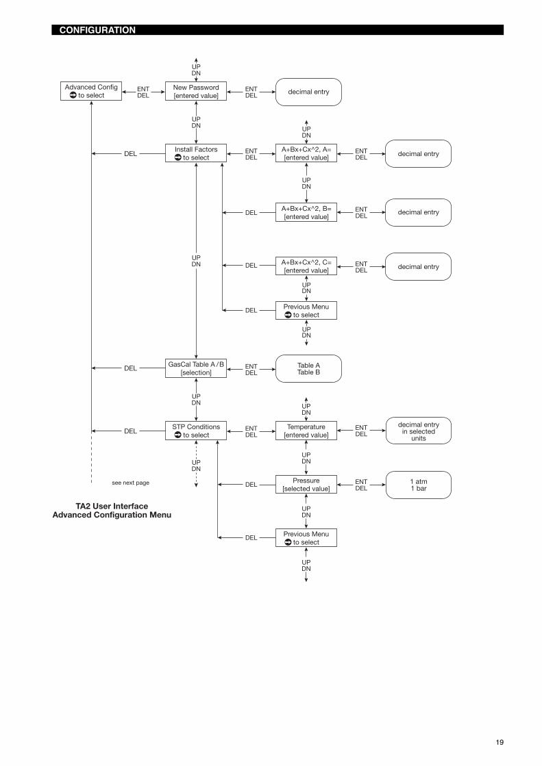
Advanced ConfigurationThe Advanced configuration menu sets advance parameters not normally used in the operation of the instrument. To accessAdvanced Configuration, scroll or until the display shows «Adv Config», press .
* Installation factor: Changes in flow profile will affect the measurements of the TA2. Advanced users have the ability to adjust themeasurements for changes in flow profile using a polynomial relationship in the form of:Corrected flow = A+Bv+Cv2
v = velocity in SFPM (Standard feet/min.). Contact Magnetrol for calculations to determine these factors.The default is B = 1; and A and C = 0. To use the correction factor, develop a relationship between the flow measured by the TA2 andthe flow measured by a second flowmeter. Curve fit the second order polynomial (above) using the output of the TA2 and the output ofthe second flowmeter for corrected flow. Then enter the appropriate values in the Advanced Configuration menu.
Display Item Action Comments«New Password
to select»to select
Change password Enter New Password Change the instrument password
«Install Factorsto select»to select
Install factors Enter new values for A, B & C Permits user to adjust flow mea-surement.*
«GasCal Table A/Bto select»to select
Gas calibration or to choose A or B Allows selection for 2 differentgasses or 2 different ranges forthe same gas
«STP Conditionsto select»to select
Standard temperatureand pressure conditions
Enter value for StandardTemperature and selectStandard Pressure value
Permits user to change STP(Standard Temperature andPressure) conditions
«Custom Unitto select»to select
Customised input Press or , then to enteroption
«Custom Units Text», enter max6 characters
Allows the user to create anydesired units of flow measure-ment
«Custom Units Mult» Allows the user to calculate the«custom unit» value
«Previous Menuto select»to select
Return to previous menu
«D/A Trim A01to select»to select
Press or , then to enterand adjust 4 mA or 20 mA point
Allows to fine tune the 4mA and20 mA points for the first gas orfirst range using the or
«D/A Trim A02to select»to select
Press or , then to enterand adjust 4 mA or 20 mA point
Allows to fine tune the 4mA and20 mA points for the second gasor second range using the or
«Previous Menuto select»to select
Previous menu Returns to previous menu
19
CONFIGURATION
Advanced Configto select
New Password[entered value]
Install Factorsto select
A+Bx+Cx^2, A=[entered value]
A+Bx+Cx^2, B=[entered value]
A+Bx+Cx^2, C=[entered value]
STP Conditionsto select
GasCal Table A /B[selection]
Temperature[entered value]
Pressure[selected value]
decimal entry
TA2 User InterfaceAdvanced Configuration Menu
decimal entry
decimal entry
decimal entry
decimal entryin selected
units
DEL
DEL
DEL
ENTDEL
UPDN
UPDN
UPDN
UPDN
UPDN
UPDN
UPDN
UPDN
UPDN
UPDN
UPDN
UPDN
UPDN
ENTDEL
DEL
ENTDEL
Table ATable B
ENTDEL
ENTDEL
ENTDEL
ENTDEL
ENTDEL
1 atm1 bar
ENTDEL
ENTDEL
DEL
DEL
DEL
DEL
see next page
Previous Menuto select
Previous Menuto select

20
CONFIGURATION
Custom Unitto select
D/A Trim A01to select
Custom Unit Text[entered value]
Custom Unit Mult[entered value]
D/A Trim 4 mA[value]
D/A Trim A02to select
D/A Trim 20 mA[value]
D/A Trim 4 mA[value]
D/A Trim 20 mA[value]
TA2 User InterfaceAdvanced Configuration Menu (cont)
[inc/dec]
[inc/dec]
[inc/dec]
[inc/dec]
decimal entry
alphanumericentry
(6 characters)ENTDEL
UPDN
UPDN
UPDN
UPDN
UPDN
UPDN
UPDN
UPDN
UPDN
UPDN
UPDN
UPDN
ENTDEL
ENTDEL
ENTDEL
ENTDEL
ENTDEL
ENTDEL
ENTDEL
ENTDEL
DEL
Secondary loopconfiguration is
only available on unitswhich have this option.
DEL
DEL
DEL
DEL
DEL
DEL
DEL
DEL
DEL
Previous Menuto select
UPDN
Previous Menuto select
UPDN
Previous Menuto select
Previous Menuto select
UPDN
UPDN
UPDN

21
CONFIGURATION
Device informationThe menu is used to display information about the device.
Display Item Action Comments«Input Local Tag» Magnetrol TA2 Press to change the tag The default can be changed to
describe the application or trans-mitter number. Max.16 charac-ters
«Magnetrol S/N» Magnetrol serial number This number is needed if infor-mation on the device is neededin the future.
«Magnetrol M/N» Magnetrol Model number Displays the number that is usedby the firmware.
«Model TA2 [ ]» Firmware version Displays the firmware versionused.
«Input HART Tag» HART Tag Press to add HART Tag Max. 8 digits and only visible onunits with HART.
«HART Poll Addr» HART Poll Adress Press to add the address Number from 0 to 15. Enter 0 fora single installation. Only visibleon units with HART
«HART Device ID» HART identification num-ber
Press to add identificationnumber
Required for units with HART. Onlyvisible on units with HART
«Previous Menuto select»to select
Previous menu Returns to previous menu
Device Infoto select
Input Local Tag[entered value]
Magnetrol S/N[value]
Magnetrol M/N[entered value]
Model TA2 [HT | NP][Ver 2.0 a0]
Input HART Tag[entered value]
HART Poll Addr[entered value]
HART Device ID[entered value]
HART configuration isavailable on units
which have HART onthe primary loop.
TA2 User InterfaceDevice Information Menu
alphanumericentry
(16 chars)
TA2-A0TA2-A1TA2-A4
alphanumericentry
(8 chars)
[inc/dec]0-15
integer entry
DEL
DEL
DEL
DEL
DEL
DEL
DEL
ENTDEL
UPDN
UPDN
UPDN
UPDN
UPDN
UPDN
UPDN
UPDN
UPDN
ENTDEL
ENTDEL
ENTDEL
ENTDEL
ENTDEL
Previous Menuto select

22
CONFIGURATION
Diagnostics MenuThe «Diagnostics» menu contains both informational items and diagnostic screens that can assist in obtaining information onthe operation of the unit and troubleshooting if faults or warnings occur.
Display Item Action Comments«History» History Press to view diagnostics Each event is indicated with an
event number. The most recentevent is shown first
«Run Time» Elapsed time since «History»was last reset
«History Reset» Resetting history log Press to reset
«Signal» Live signal reading Press to view «fixed signal».Then pressing or permits tochange the signal.
Provides a mW reading and thecalculated flow rate
«Delta Temp» Temperature difference Displays the temperature differ-ence between the 2 RTD’s
«Heater Settings» Current value Current value as sent to theheater
«Max Process Temp» Maximum process tem-perature
Press to reset the recordedtemperature
Displays the maximum tempera-ture recorded by the sensor
«Electronics Temp» Electronics temperature Displays current temperature inthe enclosure
«Max Elec Temp» Recorded maximum tem-perature
Press to reset the maximumrecorded temperature
Displays the maximum tempera-ture in the housing
«Min Elect Temp» Recorded minimum tem-perature
Press to reset the minimumrecorded temperature
Displays the minimum tempera-ture in the housing
«Probe Statusto select»to select
Probe status «OK» means the probe is opera-tional, «Shorted» or «Open»means there is a problem.Consult Magnetrol if a problem isnoted.

23
CONFIGURATION
Diagnosticsto select
History[current status]
Event nn[Diagnostic Text]
Run Timennnnh nnm nnsec
HistoryReset
Are You Sure?[selection]
Previous Menuto select
Signal xxx mWxxxx xx units
Run-time sincehistory was reset.
see next page
TA2 User InterfaceDiagnostics Menu
NoYes
DEL
DEL
DEL
DEL
DEL
DEL
DEL
DEL
DEL
DEL
ENTDEL
ENTDEL
UPDN
Eventnn Durationnnnnnh nnm nnsec
UPDN
Delta Temp[temp value]
UPDN
UPDN
UPDN
UPDN
UPDN
UPDN
Heater Setting[integer value]
Max Process Temp[max value]
Electronics Temp[current value]
Max Elec Temp[max value]
UPDN
UPDN
UPDN
UPDN
ENTDEL
Eventnn Occurrednnnnnh nnm nnsec
ENTDEL
ENTDEL
FxdSgl xxx mWxxxx xx unitsDEL
ENT
Reset?[selection]
ENTDEL
Reset?[selection]
ENTDEL
ENTDEL
NoYes
ENTDEL
NoYes
ENTDEL
ENTDEL
Min Elec Temp[min value]
Probe Statusto select
Reset?[selection]
Temp SensorOK/Shorted/Open
Flow SensorOK/Shorted/Open
NoYes
ENTDEL
UPDN
UPDN
UPDN
UPDN
UPDN
UPDN
UPDN
Probe HeaterOK/Shorted/Open
ENTDEL
ENTDEL
Previous Menuto select
24
CONFIGURATION
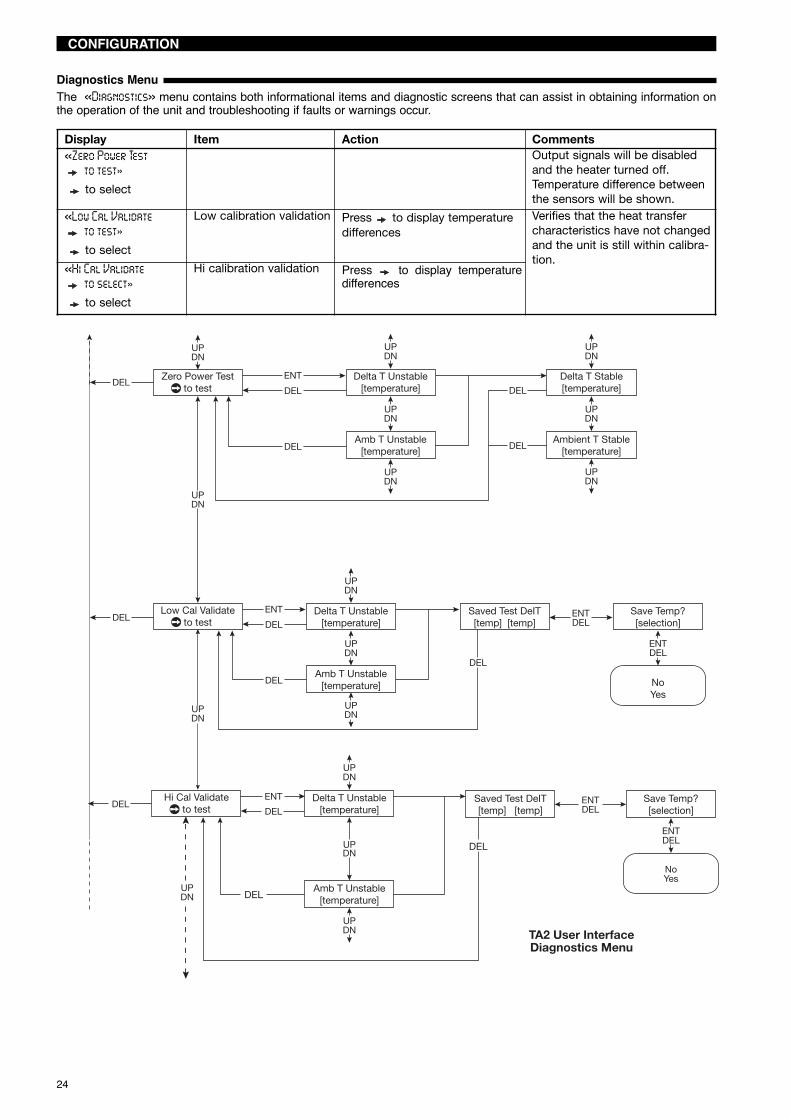
Diagnostics MenuThe «Diagnostics» menu contains both informational items and diagnostic screens that can assist in obtaining information onthe operation of the unit and troubleshooting if faults or warnings occur.
Display Item Action Comments«Zero Power Test
to test»to select
Output signals will be disabledand the heater turned off.Temperature difference betweenthe sensors will be shown.
«Low Cal Validateto test»to select
Low calibration validation Press to display temperaturedifferences
Verifies that the heat transfercharacteristics have not changedand the unit is still within calibra-tion.
«Hi Cal Validateto select»to select
Hi calibration validation Press to display temperaturedifferences
Zero Power Testto test
Delta T Unstable[temperature]
Delta T Stable[temperature]
Low Cal Validateto test
TA2 User InterfaceDiagnostics Menu
NoYes
UPDN
UPDN
UPDN
UPDN
UPDN
UPDN
UPDN
UPDN
UPDN
Amb T Unstable[temperature]
UPDN
UPDN
UPDN
ENTDEL
Amb T Unstable[temperature]
Ambient T Stable[temperature]
Delta T Unstable[temperature]
ENT
DELSaved Test DeIT[temp] [temp]
Save Temp?[selection]
ENTDEL
DEL
DEL
ENT
DEL
DEL
DEL
DEL
DELDEL
Hi Cal Validateto test
Delta T Unstable[temperature]
Amb T Unstable[temperature]
Saved Test DeIT[temp] [temp]
DEL
DEL
UPDN
ENTDEL
UPDN
UPDN
Save Temp?[selection]
ENTDEL
NoYes
DEL
ENTDEL
UPDN

25
CONFIGURATION
Diagnostics MenuThe «Diagnostics» menu contains both informational items and diagnostic screens that can assist in obtaining information onthe operation of the unit and troubleshooting if faults or warnings occur.
Display Item Action Comments«A01 Loop Test»
to select
mA Value output or to change output signal
«A02 Loop Test»to select
mA Value output or to change output signal Only shown on units that havethe optional second mA loop.
«Test Pulseto select»to select
Pulse output signal or to set the number ofpulses; then to confirm.Press to conduct test.
When the test is completed thenumber of pulses will be shown.Press two times to return toprevious menu. The device will«Time out» and return to normaloperation after 5 minutes.
TA2 User InterfaceDiagnostics Menu (cont)
5102550100250500
10002500500010000
UPDN
UPDN
UPDN
UPDN
UPDN
UPDN
UP DN
ENTDEL
[inc/dec]
ENTDEL
ENTDEL
ENTDEL
[inc/dec]
Secondary loopconfiguration isonly availableon units which
have the optionalsecondary loop.
Pulse Outputdiagnostics areonly availableon units which
have the optionalTransistor Output
interface.
A01 Loop Test[current value]DEL
A02 Loop Test[current value]DEL
Test Pulseto select
Num Test Pulses[selection]
Pulse Out TestIn Progress/Complete/Fail/Timeout
Pulse Out Testto test
DEL
DEL
DEL
ENT
DEL
UP DN
Previous Menuto select
UPDN
Previous Menuto select

26
CONFIGURATION
Factory ConfigurationThe Factory Configuration is used during initial calibration of the instrument; access to this section is generally only requiredfor review of the information.To access Factory Configurations, scroll or until the display shows «Factory Config», press .Replacement of either the probe or the logic circuit board will require re-entry of calibration data. A replacement probe will beaccompanied with a new calibration certificate which will provide the new calibration information. Replacement of the logic cir-cuit board will require re-entry of the original calibration data from the initial calibration certificate.
Display Item Action Comments
«Probe Paramsto select»to select
Probe parameters or to scroll through entries These factors will requirechanging if probe is replaced.
«Cal Parameters Ato select»to select
Parameters gas A or to scroll through entriesand compare against data on thecalibration certificate
These factors will requirechanging if probe is replaced.
«Cal Parameters Bto select»to select
Parameters gas Bor second range
or to scroll through entriesand compare against data on thecalibration certificate
These factors will requirechanging if probe is replaced.
«Control Parametersto select»to select
Control parameters or to scroll through entriesand compare against data onCalibration Certificate
These factors will requirechanging if probe is replaced.
«Module Paramsto select»to select
Module parameters Scroll through entries These are factory set values andshould not be changed.
«NSP Value» Password Set by Magnetrol
«Previous menuto select»to select
Previous menu Returns to previous menu orcycle through FactoryConfiguration.

27
CONFIGURATION
Factory Configto select
Probe Paramsto select
Cal Parameters Ato select
Cal Parameters Bto select
Control Paramsto select
Module Paramsto select
NSPValue[entered value]
If the password timer hasexpired, [entered value]
will display the encryptedvalue of the password.
Factory configuration only.
TA2 User InterfaceFactory Configuration Menu
decimal entry
decimal entry
decimal entry
DEL
DEL
DEL
DEL
DEL
DEL
DEL
DEL
DEL
UPDN
UPDN
UPDN
UPDN
UPDN
UPDN
UPDN
Coeff Ratio[entered value]
Slope[entered value]
Heater Calib
UPDN
UPDN
Power Predictor[entered value]
UPDN
Factory Param (1-5)[entered value]
UPDN
UPDN
ENTDEL
ENTDEL
ENTDEL
ENTDEL
see page 29ENTDEL
see page 29ENTDEL
see page 28ENTDEL
ENTDEL
ENTDEL
Previous Menuto select

28
CONFIGURATION
Probe parametersTo access Probe parameters first enter Factory Configuration, then or until the display shows «Probe Params», pressto enter.
Display Item Action Comments«Sensor Type»
to enterSensor type or to select type «TXR», «TXS», «TXU», «TFT»,
«Spare 1», «Spare 2», «Spare 3»can be selected
«To» Calibration parameter deter-mined when calibrating theRTD’s
«Fo» Low calibration validation Press to display temperaturedifferences
Calibration parameter deter-mined when calibrating theRTD’s
«Probe Temp Calib» Hi calibration validation Press to display temperaturedifferences
Used during calibration of theRTD’s
«Previous Menuto select»to select
Previous menu Returns to previous menu
Probe Paramsto select
Probe Temp Calib[OK/Bad/Calib
Required]
Sensor Type[selection]
To[entered value]
Fo[entered value]
TA2 User InterfaceFactory Configuration Menu
Probe Parameters
decimal entry
decimal entry
ENTDEL
UPDN
UPDN
UPDN
UPDN
ENTDEL
ENTDEL
Temp Stabilizing[lo temp ADC cnt] Flow
UPDN
UPDN
UPDN
UPDN
TXRTXSTXUTFT
Spare 1Spare 2Spare 3
ENTDEL
decimal entryENTDEL
ENTDEL
Temp Stabilizing[lo temp ADC cnt] Temp
ENT
DELEnter Probe Temp
[temp reading]
DEL
DEL
DEL
DEL
DELPrevious Menuto select

29
CONFIGURATION
Calibration parametersThere are two separate menus for calibration parameters titled «Cal Parameters A» and «Cal Parameters B». These two differ-ent sets of calibration are used when the TA2 is calibrated on two gases or two different ranges. If the unit is calibrated for air,then only «Cal Parameters A» is used. If calibrated for a different gas then the calibration parameters for the specified gas iscontained in «Cal Parameters A», the air calibration is contained in «Cal Parameters B».«Cal Parameters A» and «Cal Parameters B» have an identical menu structure.Display Item Action Comments«Calib Table ANn Points»
Calibration table respec-tive gas
Provides actual calibration datapoints
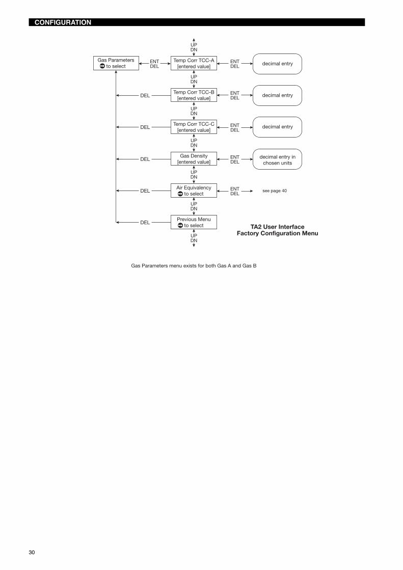
«Gas Parametersto select»to select
or to scroll throughparameters
«Temp Corr TCC-A», «Temp Corr TCC-B», «Temp Corr TCC-C»
Gas specific factors for tempera-ture compensation
«Gas density» Provides gas density at STP con-ditions
«Air equivalency» Factors relating the relationshipof the gas flow to the flow of air
«Set Point»to select
Temperature difference Only to be changed byMagnetrol
Indicates temperature differencethe device is attempting to main-tain
«Zero Flow Signal»to select
Zero flow data point Used to adjust data point forapplication specific relatedissues
«Low Flow Cutoff»to select
Low flow limit Enter the limiting value usingor . Confirm by pressing twotimes .
Flow rates below this value willbe ignored.
«Calib Pipe Area» Calibration of the pipearea
Enter the flow area using or. Confirm by pressing two
times .
«Previous Menuto select»to select
Previous menu Returns to previous menu
Cal Parameters Ato select
Calib Table Ann Points
Table A Pt nn Pwr[entered value]
Table A Pt nn Vel[entered value]Gas Parameters
to select
Set Point[entered value]
Zero Flow Signal[entered value]
Low Flow Cutoff[entered value]
Calib Pipe Areato select
decimal entry
decimal entry
decimal entry
decimal entry
see page 30
TA2 User InterfaceFactory Configuration Menu
Cal Parameters A/B
[inc/dec pt #]
DEL
DEL
DEL
DEL
DEL
DEL
ENTDEL
UPDN
UPDN
UPDN
UPDN
UPDN
UPDN
UPDN
UPDN
UPDN
ENT
ENT
ENTDEL
ENTDEL
ENTDEL
ENTDEL
ENTDEL
ENTDEL
DEL
Previous Menuto select
30
Gas Parametersto select
Temp Corr TCC-A[entered value]
Temp Corr TCC-B[entered value]
Temp Corr TCC-C[entered value]
Gas Density[entered value]
Air Equivalencyto select
see page 40
TA2 User InterfaceFactory Configuration Menu
decimal entry inchosen units
decimal entry
decimal entry
decimal entry
DEL
DEL
DEL
DEL
DEL
ENTDEL
UPDN
UPDN
UPDN
UPDN
UPDN
UPDN
UPDN
ENTDEL
ENTDEL
ENTDEL
ENTDEL
ENTDEL
Gas Parameters menu exists for both Gas A and Gas B
Previous Menuto select
CONFIGURATION

31
CONFIGURATION
Air equivalencyTo access «Air Equivalency», press .
Display Item Action Comments«Air Equiv Mode»
to enterAir equivalency mode or to enable or disable the
mode
«Gas Coeff Ag»To«Gas Coeff Eg»
to enter
Enter values using or Polynomal equation used:A+Bv+Cv2+Dv3+Ev4 where v ismass velocity. Contact Magnetrolfor factors.
Air Equivalencyto select
Air Equiv Mode[selection]
Gas Coeff Ag[entered value]
Gas Coeff Bg[entered value]
Gas Coeff Cg[entered value]
Gas Coeff Dg[entered value]
Gas Coeff Eg[entered value]
TA2 User InterfaceFactory Configuration Menu
Air Equivalency
decimal entry
decimal entry
decimal entry
DisabledEnabled
decimal entry
decimal entry
DEL
DEL
DEL
DEL
DEL
DEL
ENTDEL
UPDN
UPDN
UPDN
UPDN
UPDN
UPDN
UPDN
UPDN
ENTDEL
ENTDEL
ENTDEL
ENTDEL
ENTDEL
ENTDEL
Air Equivalency menu exists for both Gas A and Gas B
Previous Menuto select

32
CONFIGURATION USING HART®
IMPORTANT: The digital HART® communication is superimposed on the4-20 mA output and requires a min. load resistance of 250 Ω and a max loadresistance of 1000 Ω.
Junction
Analog output 1Output
Active or passiveconnections
TB3
AC Power input(100 - 264 V AC)
TB1
DC Power input(11 - 29 V DC)
TB2
ControlRoom
Display
PowerSupply
CurrentMeter
RL > 250 Ω
CONNECTIONS
To confirm HART® handheld communications, attach the unit as shown in the illustration. If the communicator reads GENER-IC on the first two lines, then the HART® handheld does not contain the current DDs (Device Descriptions) for the TA2 meter.Contact your local HART® Service Center
Wiringcompartment
+-
F1TEST
F2 TEST
POWERLOOP2
OUTPUT
100-264 VAC
L1L2
DC INPUT
+- P- A+ P-
LOOP1/HARTOUTPUT
PULSE/
P+P-
50/ 60Hz
INPUTAC
A-P+ A-
P+ A+
ALARM
TB3D6TB4TB2
TB5
R1
F1
TB1
HART Version HCF Release Date Compatible with TA2 Software
Dev V1 DD V1 March 2010 Version 2.0a0

33
CONFIGURATION USING HART®
HART® MENU
1 BasicConfiguration
2 I/OConfiguration
3 AdvancedConfiguration
4 Device Information
5 FactoryConfiguration
6 Review
1 System Units2 Flow Area
1 Flow Units2 Mass Units3 Temperature Units4 Density Units5 Totalizer Units6 Diameter Units7 Area Units
1 Pipe ID(flow body ID if TFT)
2 Flow Area
1 PV is2 AO1 Lwr Range Val3 AO1 Upr Range Val4 Fault State
1 Totalizer Units2 R Totalizer Mode3 R Totalizer Mult4 R Totalizer5 R Totalizer Time6 Reset Totalizer7 NR Totalizer Mult8 NR Totalizer9 NR Totalizer Time
1 AO1 Loop Config
2 AO2 Loop Config
3 Variable Mapping
4 Totalizers
5 Transistor Output6 Damping7 Poll Address
1 SV is2 AO2 Lwr Range Val3 AO2 Upr Range Val
1 TV is2 QV is
1 Pulse Units2 Pulse Multiplier3 Pulse Max Freq
1 Pulse Output2 Alarm3 Disable
1 Output Function2 Pulse Output Config3 Alarm Config
1 Alarm Setpoint2 AlarmOperation
1 Low Flow2 High Flow
1 Table A2 Table B
1 Install Factors2 Gas Cal Table3 STP Conditions4 Custom Unit5 New User Password6 D/A Trim AO17 D/A Trim AO2
1 A2 B3 C
1 STP Temperature2 STP Pressure
1 Custom Unit Text2 Custom Unit Mult
1 Device Setup2 Diagnostics �
3 PV4 PV Loop5 PV % Range6 SV7 SV Loop8 SV % Range9 Process Variables
1 Flow2 Mass3 ProcessTemperature
4 R Totalizer5 R Totalizer Time6 NR Totalizer7 NR Totalizer Time8 Custom Unit
� See page 36.

34
CONFIGURATION USING HART®
HART® MENU
1 Local Tag2 Descriptor3 HART Tag4 Poll Address5 Date6 Message7 Date/Time/Initials8 Manufacturer9 Model Number10 Specific Model11 Firmware Version12 Magnetrol S/N13 Device ID14 Final asmbly num
1 Enter Password2 Probe Parameters3 Control Parameters4 Module Parameters5 NSP Value6 Cal Parameters A7 Cal Parameters B
1 Heater Calibration2 Calibrate Heater
1 Sensor Type2 To3 Fo4 RTD Calibration5 Calibrate RTDs
1 TXR2 TXS3 TXU4 TFT5 Spare 16 Spare 27 Spare 3
1 TCC-A2 TCC-B3 TCC-C4 Gas Density5 Air Equivalency
1 TCC-A2 TCC-B3 TCC-C4 Gas Density5 Air Equivalency
1 Enable/Disable2 Ag3 Bg4 Cg5 Dg6 Eg
1 Enable/Disable2 Ag3 Bg4 Cg5 Dg6 Eg
1 BasicConfiguration
2 I/OConfiguration
3 AdvancedConfiguration
4 Device Information
5 FactoryConfiguration
6 Review
1 Device Setup2 Diagnostics3 PV4 PV Loop5 PV % Range6 SV7 SV Loop8 SV % Range9 Process Variables
1 Cal Table B2 Gas Parameters3 Set Point4 Zero Flow Signal5 Low Flow Cutoff6 Cal Pipe Area
1 Cal Table A2 Gas Parameters3 Set Point4 Zero Flow Signal5 Low Flow Cutoff6 Cal Pipe Area
1 Coeff Ratio2 Slope3 Power Predictor4 Factory Parameter 15 Factory Parameter 26 Factory Parameter 37 Factory Parameter 48 Factory Parameter 5

35
CONFIGURATION USING HART®
HART® MENU
1 Model2 Manufacturer3 Magnetrol S/N4 HART Tag5 Descriptor6 Firmware Version7 Date8 Message9 Final asmbly num10 Device ID11 Poll Address12 Date/Time/Initials13 Universal rev14 Fld Dev rev15 Software rev16 Num req preams17 PV is18 SV is19 TV is20 QV is21 Pipe ID22 Flow Area23 AO1 Lwr Range
Value24 AO1 Upr Range
Value25 Fault State
26 Damping27 AO2 Lwr Range
Value28 AO2 Upr Range
Value29 R Totalizer Mode30 R Totalizer Mult31 NR Totalizer Mult32 Output Function33 Pulse Units34 Pulse Multiplier35 Pulse Max Freq36 Alarm Setpoint37 Alarm Operation38 Install Factor A39 Install Factor B40 Install Factor C41 Gas Cal Table42 STP Temperature43 STP Pressure44 Custom Unit Text45 Custom Unit
Multiplier46 AO1 4mA Trim value47 AO1 20mA Trim value48 AO2 4mA Trim value49 AO2 20mA Trim value
1 BasicConfiguration
2 I/OConfiguration
3 AdvancedConfiguration
4 DeviceInformation
5 FactoryConfiguration
6 Review
1 Device Setup2 Diagnostics3 PV4 PV Loop5 PV % Range6 SV7 SV Loop8 SV % Range9 Process Variables

36
1 View History2 Reset History
1 PV2 Signal3 Exit Fixed Signal4 Fixed Signal Value
1 Current Temperature2 Max Temperature3 Min Temperature4 Reset Temperatures
PV Out of limitsNon-PV Out of limitsLoop Current SaturatedLoop Current FixedMore status availableCold startConfiguration changedDevice malfunction
Default ParamsFault 1No Probe SignalsTemp Snsr ShortedTemp Snsr OpenFlow Snsr ShortedFlow Snsr OpenRTDs ReversedHeater ShortedHeater OpenZFS Too HighToo Few Cal PtsAir Equiv CoeffUser CoeffModule FailureVel > UprSnsr Lmt
InitializingAO2 Loop FixedIn Test ModeVel > Upr Cal PtVel < Low Flow LmtRTD Drive CurrentDflt TotalizerPulse Mult ErrorWarning 2AO1 Loop Trim ReqdAO2 Loop Trim ReqdProcess Temp HighCheck Install FactorsElec Temp HiElec Temp LoWarning 1
1 Current Temperature2 Max Temperature3 Reset Temperatures
1 Signal/PV2 Delta T3 Heater Setting4 Process Temperature5 Elect Temperature6 Zero Power Test7 Low Cal Validation8 High Cal Validation9 AO1 Loop Test10 AO2 Loop Test11 Test Pulse
AO2 Loop FixedAO2 Loop SaturatedSet Pt > UprCalPtRange Too SmallSystem code
1 Device Status2 Reset Config chgd3 Faults4 Warnings5 Informational
1 Present Status
2 History
3 Extended Diagnostics
4 Trend Chart
1 Device Setup2 Diagnostics3 AO14 AO1 Loop5 AO1 % Range6 AO27 AO2 Loop8 AO2 % Range9 Process Variables
CONFIGURATION USING HART®
HART® MENU

37
DIAGNOSTICS TEST
Heater setting
Zero power test
Calibration verification procedure
The TA2 has several diagnostics tests which may be routinely performed. When conducting these tests, the reported flow ratewill be zero.
The amount of current flowing to the heater is displayedunder Diagnostics/Heater Setting. This value can be veri-fied by connecting a multi-meter across the Heater Bypassterminals (J2. This board can be accessed by opening thecover and removing the display module.The measured value should match the value shown on thedisplay. Any difference between the two values indicatesthat the heater calibration is incorrect. If the heater circuit isopen, a nominal current value will be displayed, but themeasured current will be zero.
This test checks that the resistances of the RTDs have notchanged. The heater is turned off and the temperature dif-ference between the two sensors is compared. This testshould be performed either in a water bath (preferred) orunder flowing conditions. Conducting this test in still air willcause the test to time out and provide inconclusive results.
The temperature difference between the two sensors is dis-played. These values should match within 0,15 °C whentest performed in a water bath. Temperature differenceunder flowing gas may be as high as 0,5 °C dependingupon flow rate. If greater than this value, drift in the RTDsmany have occurred.
The TA2 measures heat transfer. These procedures aredesigned to permit the user to verify the calibration bychecking the heat transfer characteristics of the sensor. Ifthe heat transfer characteristics are approximately thesame when the test is conducted compared with when thesame data was collected at the factory during the initial cal-ibration, the unit remains in calibration.The procedure is performed under two different sets of con-ditions. Both tests should be conducted at “room tempera-ture”; approximately +21 °C to +30 °C (+70 °F to +85 °F).The test can be performed using the keypad and display,HART®, or PACTware™. During the test, the display (orHART® or PACTware™) will provide an indication ofthe measured temperature difference and if the Delta Tmeasurement is stable.Low Flow Validate—Simulates a low flow condition.1. Cover sensor tips to isolate from air currents. During
the test, the heater power is set and the Delta T (tem-perature difference) between the two RTDs is mea-sured.
2. After completion of the test, the value of the tempera-ture difference measured during the test is comparedagainst the previously stored value. (The original valueobtained when the units were initially calibrated can befound on the original calibration certificate.)
3. The value from the test should compare with thestored (or original calibration value) within 1,5 °C. Thisvariation in part is due to potential variations of theambient temperature during the test and differences intest methods.
High Flow Validate—Simulates a high flow condition.1. Support the TA2 vertically in a water bath. See picture
below. During the test, the heater power is set and theDelta T (temperature difference) between the twoRTDs is measured.
2. After completion of the test, the value of the tempera-ture difference measured during the test is comparedagainst the stored value. (The original value obtainedwhen the units were initially calibrated can be found onthe original calibration certificate.)
3. The value from the test should compare with thestored (or original calibration value) within 1,5 °C. Thisvariation in part is due to potential variations of theambient temperature during the test and differences intest methods.
If the temperature difference measured during the test isgreater than the recommended temperature difference indi-cated above in item “3”, then the overall accuracy of theTA2 may be affected. Contact Magnetrol Technical support.
1
1
2 1
Heater testJ2 (2-pin)
DisplayJ1 (2 x 7 pin)
TA2 processor board

38
MAINTENANCE
Error messages
Troubleshooting
The TA2 Mass Flow Meter utilizes a 3-level hierarchy forreporting diagnostics information: FAULTS, WARNINGS,and INFORMATION. Faults and Warnings can be reviewedon the rotating screen in the Home menu. These screenscapture only current conditions. Historic diagnostic infor-mation can be viewed in the HISTORY screen of theDiagnostics Menu.FAULT: The highest level in the hierarchy of diagnostics. AFault indicates a defect or failure in the circuitry or software,or a calibration condition that makes reliable measurementimpossible. The mA value defaults to 3.6 mA, 22 mA, orHOLD and a message is displayed on the rotating screen.Further error information can be obtained by reviewing theDiagnostic Menu screen.
WARNING: This is the second level in the hierarchy ofdiagnostics. A Warning indicates conditions that are notfatal but may affect the measurement. A message willappear on the Home (rotating) screen when a Warning isdetected but will not affect the output current. Further errorinformation can be obtained by reviewing the DiagnosticMenu screens.INFORMATION: This is the lowest level in the hierarchy ofdiagnostics. Information messages are for conditions thatprovide operational factors that are not critical to the mea-surement. Further error information can be obtained byreviewing the Diagnostics Menu.
Symptom Problem Solution
No output signalNo display
No input power Verify that LED D6 on the input wiring board ison. If not, check wiring connections. Check F1test and F2 test to check fuses protecting inputwiring.
No output signal 4–20 mA outputnot operational
Verify that 4–20 mA connections are made tothe correct terminals on TB3.
Flow measurement on displayis correct but output signalalways 4 mA
HART poll addressis not 0
Change HART Poll Address to 0.
Totalizer not operating Totalizer is disabled Ensure that the totalizer operationis enabled.
Flow is measured under ano flow condition
Increased heat transfer.This can occur under noflow with increased pres-sure.
Increase the low flow cutoff to a value greaterthan the displayed flow rate.The TA2 will ignore readings lower than thisvalue. Optionally, increase the zero flow signalto match the value indicated under signal value.
Flow rate too high or too low
Instrument configurationdoes not match actualapplication
Check values entered for flow area under basicconfiguration. Check if install factors are enteredunder advanced configuration. Check STP con-ditions under advanced configuration.
Buildup on sensor Depending on type and size of buildup, flowreadings may either increase or decrease.Clean sensor.
Flow rate too high Flow profile considera-tions
The TA2 assumes a specific fully developed flowprofile. User can correct for variations in flowprofile using the install factors found underadvanced configuration
Flow rate too high,output spiking
Moisture in the gas Condensed moisture will cool the sensor morethan gas flow. This will temporarily indicate ahigher than expected flow rate.

39
MAINTENANCE
Error messages
Diagnostic Fault Description/Corrective Action LCD Message
Non-VolatileMemory corruption
Partial corruption of the Non-Volatile memory stored in theEEPROM. Data may revert to Default conditions. Re-verifythat all calibration and configuration factors in the TA2 matchthe calibration certificate.
Default Params
No signal from ProbeThere is no signal from the sensor. Check the wiring betweenthe probe and the electronics.
No Probe Signals
Temperature SensorFailure
A short has occured in the RTD measuring the process tem-perature or in the interconnecting wiring (if remote electronics).Check wiring to the probe.
TempSnsr Shorted
Temperature SensorFailure
There is an open circuit in the RTD measuring the processtemperature or in the interconnecting wiring(if remote electronics). Check wiring to the probe.
Temp Sensor Open
Flow Sensor FailureA short has occured in the RTD measuring theheated sensor or in the interconnecting wiring(if remote electronics). Check wiring to the probe.
FlowSnsr Shorted
Flow Sensor FailureThere is an open circuit in the RTDs measuring theheated sensor or in the interconnecting wiring(if remote electronics). Check wiring to the probe.
Flow Sensor Open
RTDs ReversedThe wiring connecting the RTDs is reversed.Check probe wiring or interconnecting cable(if remote electronics)
RTDs Reversed
Heater ShortedThe heater has developed a short either in the probe or in theinterconnecting cable (if remote electronics). Check probewiring.
Heater Shorted
Heater OpenThere is an open circuit in the wiring going to the heater. Checkwiring. Also, check if the two-pin jumper is missing.
Heater Open
Zero Flow Signalis too high
Zero Flow Signal (power) is greater than second data point inthe Calibration Table. Check value entered under FactoryConfig/Cal Parameters/Zero Flow Signal.
ZFS Too High
Too FewCalibration Points
The calibration table does not contain sufficient number ofdata points for the flow range. Minimum of ten points isrequired.
Too Few Cal Pts
Air EquivalencyCoefficients incorrect
The Air Equivalency factors used result in a non-monotonical-ly increasing curve over the operating range. Check factors.
Air Equiv Coeffs Bad
Install Factorsincorrect
Install factors entered under Advanced Configuration result in anon-monotonically increasing curve.Check factors.
User Instl Coeffs Bad
Module Failure
No readings received from the ADCs, or the values out ofrange. Indicates failure of Analog to Digital converters. Requiresreplacement of logic board or return of unitto factory.
Module Failure
Velocity is greater thanthe Upper Sensor Limit
The velocity is greater than established values.Contact Magnetrol.
Vel > UprSnsrLmt
FAULT
40
MAINTENANCE
Error messages
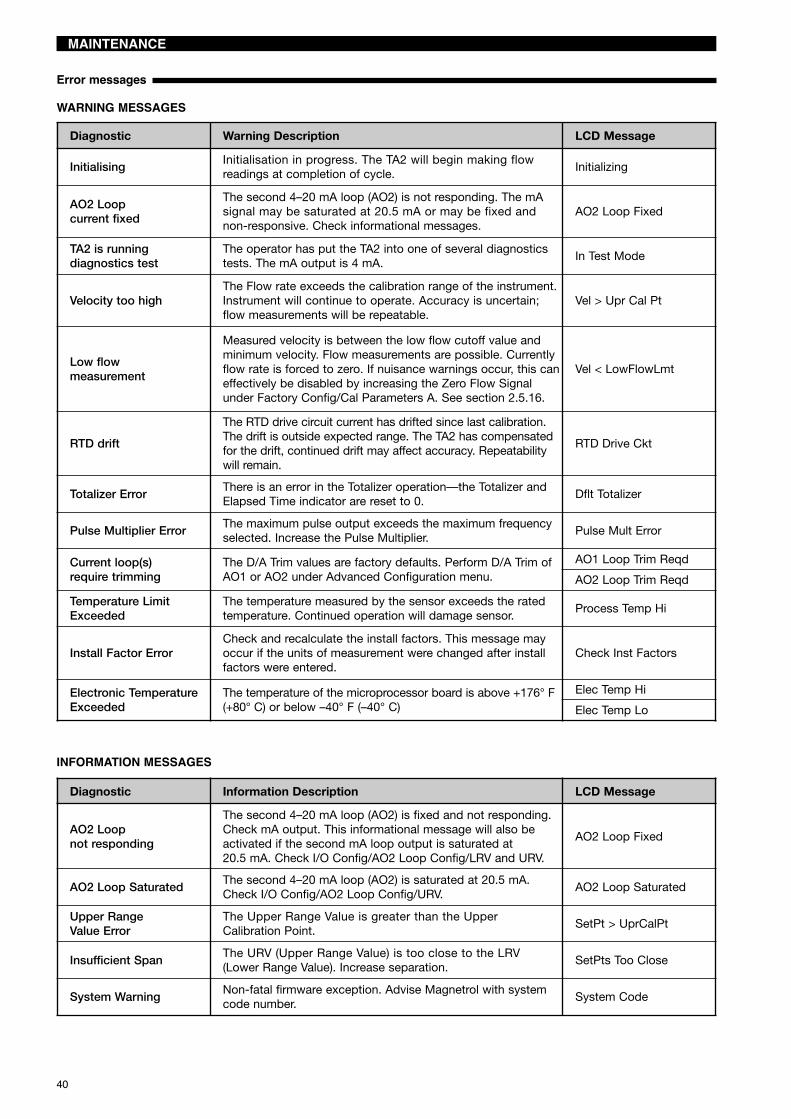
WARNING MESSAGES
INFORMATION MESSAGES
Diagnostic Warning Description LCD Message
InitialisingInitialisation in progress. The TA2 will begin making flowreadings at completion of cycle.
Initializing
AO2 Loopcurrent fixed
The second 4–20 mA loop (AO2) is not responding. The mAsignal may be saturated at 20.5 mA or may be fixed andnon-responsive. Check informational messages.
AO2 Loop Fixed
TA2 is runningdiagnostics test
The operator has put the TA2 into one of several diagnosticstests. The mA output is 4 mA.
In Test Mode
Velocity too highThe Flow rate exceeds the calibration range of the instrument.Instrument will continue to operate. Accuracy is uncertain;flow measurements will be repeatable.
Vel > Upr Cal Pt
Low flowmeasurement
Measured velocity is between the low flow cutoff value andminimum velocity. Flow measurements are possible. Currentlyflow rate is forced to zero. If nuisance warnings occur, this caneffectively be disabled by increasing the Zero Flow Signalunder Factory Config/Cal Parameters A. See section 2.5.16.
Vel < LowFlowLmt
RTD drift
The RTD drive circuit current has drifted since last calibration.The drift is outside expected range. The TA2 has compensatedfor the drift, continued drift may affect accuracy. Repeatabilitywill remain.
RTD Drive Ckt
Totalizer ErrorThere is an error in the Totalizer operation—the Totalizer andElapsed Time indicator are reset to 0.
Dflt Totalizer
Pulse Multiplier ErrorThe maximum pulse output exceeds the maximum frequencyselected. Increase the Pulse Multiplier.
Pulse Mult Error
Current loop(s)require trimming
The D/A Trim values are factory defaults. Perform D/A Trim ofAO1 or AO2 under Advanced Configuration menu.
AO1 Loop Trim Reqd
AO2 Loop Trim Reqd
Temperature LimitExceeded
The temperature measured by the sensor exceeds the ratedtemperature. Continued operation will damage sensor.
Process Temp Hi
Install Factor ErrorCheck and recalculate the install factors. This message mayoccur if the units of measurement were changed after installfactors were entered.
Check Inst Factors
Electronic TemperatureExceeded
The temperature of the microprocessor board is above +176° F(+80° C) or below –40° F (–40° C)
Elec Temp Hi
Elec Temp Lo
Diagnostic Information Description LCD Message
AO2 Loopnot responding
The second 4–20 mA loop (AO2) is fixed and not responding.Check mA output. This informational message will also beactivated if the second mA loop output is saturated at20.5 mA. Check I/O Config/AO2 Loop Config/LRV and URV.
AO2 Loop Fixed
AO2 Loop SaturatedThe second 4–20 mA loop (AO2) is saturated at 20.5 mA.Check I/O Config/AO2 Loop Config/URV.
AO2 Loop Saturated
Upper RangeValue Error
The Upper Range Value is greater than the UpperCalibration Point.
SetPt > UprCalPt
Insufficient SpanThe URV (Upper Range Value) is too close to the LRV(Lower Range Value). Increase separation.
SetPts Too Close
System WarningNon-fatal firmware exception. Advise Magnetrol with systemcode number.
System Code

41
MAINTENANCE
Circuit board replacement
Probe replacement
The Input Wiring Board, Display Module, and the PowerLoop Board can be replaced without any effect on the per-formance and operation of the TA2. The processor boardcontains the calibration information and is matched with theprobe. If this circuit board is replaced, re-entry of all theoriginal calibration and configuration information isrequired. This information is contained on the calibrationcertificate which can be supplied by Magnetrol. Use ofPACTware™ is recommended for re-entry of this data.1. Make sure the power source is turned off.2. The Input Wiring Board is contained on the wiring side
with the display module, power loop board and proces-sor board contained in the electronics compartment.
3. Remove appropriate cover.4. If removing boards in the electronics compartment:
a. Remove and unplug the display module if provided.b. Remove the two hex head fasteners using a 1⁄4"
socket. This will remove the electronics module con-taining the processor board and the power loopboard.
c. Unplug the electrical connection at J1 of the powerloop board.
d. Probe wiring connections are made to TB1 on thesame side of the power loop circuit board.
e. Connect the probe wires as indicated:Integral Electronics
Remote Electronics—see page 5.f. Reattach the electrical connection to J1.g. Reassemble the circuit boards in the enclosure.
Make sure that the probe wiring does not get pinchedbetween the standoffs on the circuit board and theattachment lugs in the housing.
h. Reinstall the display module if provided.5. If replacing the input wiring board, loosen screws, and
remove the electrical connection to J1 on the rear of thecircuit board.i. Attach electrical connections to J1 on new circuit
board and reassemble.6. Re-install the cover.7. Apply power to the instrument.8. Proceed to section RTD calibration on page 42.
The probe and processor board are calibrated together toform a matched set. If a probe needs to be replaced,Magnetrol will provide a new calibration certificate. Theuser will be required to re-enter the calibration table into theinstrument. Use of PACTware™ is recommended for re-entry of this data. A new serial number will be designatedto the replacement probe.Integral Electronics1. Make sure the power source is off.2. Access the power loop circuit board following proce-
dure in previous section circuit board replacement.3. Disconnect wiring to the probe.4. Loosen the two set screws at the base of the housing.
One serves as a rotational lock, the other secures thehead into place.
5. Unthread the probe.6. Thread in a new probe.7. Connect the probe wires to the power loop board as
indicated in previous section, step “4.e”.8. Reassemble the electronics following previous section
circuit board replacement.
9. Align the enclosure with the desired probe position,making sure that the flow arrow indicates the directionof flow.
10. Retighten the two set screws.11. Reapply power.12. Proceed to section RTD calibration on page 42.Remote Electronics1. Make sure the power source is off.2. Remove cover of remote electronics housing.3. Remove bezel.4. Disconnect the wires from the probe at terminal TB1.5. Loosen the two set screws at the base of the housing.
One serves as a rotational lock, the other secures thehead into place.
6. Unthread the probe.7. Thread in a new probe.8. Connect the probe wires to Terminal TB1 as shown in
the figure on page 5.9. Retighten the two set screws.
10. Re-assemble the bezel and install cover.11. Reapply power.12. Proceed to section RTD calibration on page 42.
Wire Color Connection on TB1Orange 8Brown 7Black 3Blue 2White 1
Wire Color Terminal Connection on TB1White 1
Blue 2
Black 3
Brown 4
Orange 5

42
MAINTENANCE
RTD calibration
Flow recalibration
If either the probe or the logic board is replaced in the field,calibration of the RTDs in the probe will return the TA2 tolike-new performance. NOTE: If this procedure is not fol-lowed, the accuracy will be affected; however, very repeat-able flow measurements will be obtained.Locate the sensor vertically in a water bath with an accu-rate temperature sensor directly adjacent to the probe tips.It is preferable that the water is stirred during the calibrationto ensure the TA2 pins and temperature probe are at thesame temperature. Using the keypad and display, select
«Factory Config\Probe Params\Probe Temp Calib» and thenpress the key. The device will dynamically display theTo/Fo readings over a period of time. After 3 minutes, andif the readings are stable enough, the display automatical-ly changes to request entry of a password (126) followed bythe ambient water temperature. After the temperature isentered, the device will display if the calibration is OK. Thedevice then automatically resets itself for normal operation.A similar procedure exists for the DD and DTM.
Calibration of the TA2 requires a flow bench or othermethod for determining the flow rate. Using this procedure,the user can re-calibrate the unit himself or use a local flowcalibration facility rather than returning the unit to the facto-ry for recalibration. With an insertion probe, it is not neces-sary to calibrate in the same size pipe as the unit isinstalled in. The TA2 has internal scale-up factors whichadjusts the data from the calibration pipe size to the instal-lation pipe size.Calibration requires the TA2 sensor to be positioned in atest section; the test section should have a sufficientupstream and downstream straight run to ensure the for-mation of a fully developed flow profile. Calibration shouldbe performed using the same gas which the unit is cali-brated for. Optionally, an air equivalency calibration can beperformed. In this case, calibrate in air and contact the fac-tory for air equivalency factors and equivalent air calibra-tion rate.Recalibration Procedure:1. Select the set point; this is the temperature in degrees
Celsius which the TA2 maintains between the two sen-sors. If the unit is re-calibrated for the same application,then it is probably not necessary to change the originalvalue. If it becomes necessary to change the set pointdue to change in the calibration velocity or the type ofgas:a. Record the set point under «Factory Config\Cal
Parameters (A or B)\Set Point».b. Determine the maximum velocity in Nm/h which the
unit will operate (Nm/h equals the Nm3/h divided bythe flow area of the test section in square meter).
c. Install the probe in the test section and flow gas thatis equivalent to the maximum velocity in the calibra-tion range.
d. Using the display, HART, or PACTware™, obtain thesignal value in mW from the Diagnostics menu.
e. Calculate a new set point using the formula:New set point = old set point x (800/measured signal(mW)). 800 mW is the desired maximum power ratingfor the TA2.
f. Enter new set point in TA2 under «FactoryConfiguration/Cal Parameters (A or B)/Set Point».
2. Convert the flow rate in the application to the flow rate inthe test section using the formula:
Flow in test section = application flow x (flow area oftest section/flow area of application)
a. Allow a flow of a known amount of gas through thetest section, recording flow rate and TA2 signal (mW).A minimum of 10 and a maximum of 30 data pointsincluding a zero flow value should be obtained. Onedata point should be taken at a flow rate approxi-mately 20 % greater than the expected operatingrange. The higher the number of data points, the bet-ter the overall accuracy of the instrument.
b. Convert the flow rate in the test section to massvelocity in Nm/h (normal meter/hour). This is equiva-lent to the flow rate in Nm3/h divided by the flow areain square meter. Convert from other units of mea-surement as necessary. Use Magnetrol STP condi-tions of 21 °C and 1 Atmosphere.
c. Enter the Power and the corresponding MassVelocity into the TA2. This is easily performed usingPACTware™ but can also be entered directly into theTA2 using the display and keypad or using HART.These values should be entered in increasing orderto ensure a monotonically increasing curve.Note password of 126 is required for entry of calibra-tion data. (Contact Magnetrol if issues using thispassword.)
d. After completion of entry of the calibration data,check the display/HART®/PACTware™ for the num-ber of points accepted (or table length). If this numberis less than the actual number of data points entered,then there is an error in the entry of the calibrationdata. Ensure that the data is entered so the curve ismonotonically increasing. The values of mass veloci-ty and power should always be increasing over thecalibration range.
e. A Fault message will occur if there are fewer than 10calibration data points in the calibration table.
3. Enter the flow area of the calibration test section. Unitsof measurement are the same as selected under BasicConfig menu. This value is used in calculating the scale-up factor between the calibration test section and theinstallation.

43
REPLACEMENT PARTS
NOTE: Replacement of the logic PC board or the sensor requires entry of configuration data from the CalibrationCertificate.
CAUTION: EXPLOSION HAZARDDo not disconnect equipment unless power has been switched off or the area is known to benon-hazardous.
1X 742 3 8 9 105 6Digit in partn°:
T A 2Partn°: Serial n°:
X = product with a specific customer requirement
IMPORTANT NOTICE: See nameplate, always provide complete partn° and serial n° when ordering spares.
(2) Display moduleDigit 6 Replacement part
0 not applicableB Z30-3614-001
(1) Housing coverDigit 6 Replacement part
0 004-9197-007B 036-4411-001
(8) Housing coverDigit 9 Replacement part
3 not applicable4 004-9193-003
(9) "O" ringDigit 9 Replacement part
3 not applicable4 012-2201-237
(4) Wiring PC boardDigit 5 Replacement part
1 089-7260-0014 089-7260-002
(3) Electronic moduleDigit 5 Digit 9 Replacement part
1 3 or 4 089-7261-002
4 3 or 4 089-7261-003
Replacement part(5) Housing cover 004-9206-010(6) "O"-ring 012-2201-240(7) "O"-ring 012-2201-240
(10) Sensor consult factory
1
2
3
6 79
8
10
4
5

44
SPECIFICATIONS
Electronics specifications
Performance
Probe specifications
Description SpecificationPower supply 11,6 – 30 V DC (11,6 V DC for integral electronics only)
100 – 264 V AC, 50-60 HzPower consumption DC = 6,8 watts, AC = 7 VA typical, 11,9 VA maximum
Analog OutputActive 4-20 mA isolated (3,8 – 20,5 mA useable as per NAMUR NE 43) -
max 1000 Ω loop resistancePassive 4-20 mA isolated (3,8 – 20,5 mA useable as per NAMUR NE 43) -
max loop resistance depending power supplyResolution Analog 0,01 mA
Display 0,01 Nm/sCalibration Pre-calibrated from factory - NIST traceableDamping Adjustable 0-15 s time constantDiagnostic Alarm Adjustable 3,6 mA, 22 mA or Hold last outputUser Interface 4-button keypad and/or HART® communicatorPulse Output Active connection – 24 V DC Power, 150 mA
Passive connection – 2,5 to 60 V DC Power, 1,5 AAlarm Output Active connection – 24 V DC Power, 100 mA
Passive connection – 2,5 to 60 V DC Power, 1 ADisplay 2-line x 16-character backlit LCDDisplayed values Flow (eg. Nm3/h, Nl/h) and/or mass flow (eg. kg/h) and/or temperature (°C/°F)
and/or loop current (mA) and/or totalized flow (eg. Nm3/h, Nl/h)Menu Language English, French, German, Spanish, RussianHousing Material IP 66, Aluminium A 356 (< 0,2 % copper) dual compartmentApprovals ATEX II 2 G Ex d IIC T6 Gb, flameproof enclosure
Other approvals are available, consult factory for more detailsSIL (Safety Integrity Level) Functional safety to SIL1 as 1oo1 / SIL2 as 1oo2 in accordance to IEC 61508 – SFF: 88,4 %.
Full FMEDA report and declaration sheets available at requestShock/Vibration Class ANSI/ISA-S71.03 Class SA1 (Shock), ANSI/ISA-S71.03 Class VC2 (Vibration)Net weight 3,3 kg (7.3 lbs) – electronics with 25 cm threaded probe
Description SpecificationTurn down ratio 100:1 typical (depending upon calibration)Flow range Max 0,05 - 250 Nm/s (10 - 50,000 SFPM) reference of air at STP conditions
Min 0,05 - 2,5 Nm/s (10 - 500 SFPM) reference of air at STP conditionsLinearity Included in flow accuracyAccuracy Flow ± 1 % of reading + 0,5 % of calibrated full scale
Temperature ± 1 °C (2 °F)Repeatability ± 0,5 % of readingResponse time Time constant of 1 to 2 sRemote electronics Max 60 m or 150 m, depending on cable used - for longer lengths, consult factoryAmbient temperature -40 °C to +80 °C (-40 °F to +176 °F) (ATEX up to +55 °C (+130 °F))
Display: -30 °C to +80 °C (-22 °F to +176 °F)Operating temperature effect ± 0,04 % per °CHumidity 0-99 %, non-condensingElectromagnetic Compatibility Meets CE requirements (EN 61326: 1997 + A1 + A2)
Description Insertion probe Sensor with flow body
Materials – wetted parts 316/316L (1.4401/1.4404) or Hastelloy® C (2.4819) Sensor: 316/316L (1.4401/1.4404)Flow body: stainless steel or carbon steel
Mounting Threaded, compression fitting, ANSI-EN (DIN)flanged or with Retractable probe assembly Threaded or flanged
Probe length From 7 cm up to 253 cm (2.6" up to 99.9") Flow body sizes from 1/2" up to 4"
Max. process temperatureIntegral electronics: -45 °C up to +120 °C (-50 °F up to +250 °F)
-45 °C up to +200 °C (-50 °F up to +400 °F) with 100 mm (4") longer probe servingas heat extension between the electronics and the compression fitting
Remote electronics: -45 °C up to +200 °C (-50 °F up to +400 °F)
Max pressure rating103 bar @ +20 °C (1500 psi @ +70 °F)94,8 bar @ +200 °C (1375 psi @ +400 °F) – direct insertion75,9 bar @ +200 °C (1100 psi @ +400 °F) – with flow body

45
SPECIFICATIONS
Code SizeMax flow rate
Air, N2, O2Natural Gas,Methane
DigesterGas
Propane Hydrogen CO2, Argon
0 1/2"145 Nm3/h85 SCFM
100 Nm3/h60 SCFM
100 Nm3/h60 SCFM
50 Nm3/h30 SCFM
35 Nm3/h20 SCFM
140 Nm3/h80 SCFM
1 3/4"275 Nm3/h160 SCFM
195 Nm3/h115 SCFM
195 Nm3/h115 SCFM
95 Nm3/h55 SCFM
70 Nm3/h40 SCFM
250 Nm3/h150 SCFM
2 1" 460 Nm3/h270 SCFM
320 Nm3/h190 SCFM
320 Nm3/h190 SCFM
160 Nm3/h95 SCFM
115 Nm3/h65 SCFM
435 Nm3/h255 SCFM
3 11/2"1120 Nm3/h660 SCFM
780 Nm3/h460 SCFM
780 Nm3/h460 SCFM
390 Nm3/h230 SCFM
275 Nm3/h160 SCFM
1060 Nm3/h625 SCFM
4 2" 1640 Nm3/h965 SCFM
1160 Nm3/h680 SCFM
1160 Nm3/h680 SCFM
600 Nm3/h350 SCFM
450 Nm3/h265 SCFM
1560 Nm3/h920 SCFM
5 3" 4580 Nm3/h2700 SCFM
3210 Nm3/h1890 SCFM
3210 Nm3/h1890 SCFM
1170 Nm3/h690 SCFM
1230 Nm3/h730 SCFM
4360 Nm3/h2565 SCFM
6 4" 8260 Nm3/h4860 SCFM
5780 Nm3/h3400 SCFM
5780 Nm3/h3400 SCFM
2090 Nm3/h1230 SCFM
2225 Nm3/h1310 SCFM
7845 Nm3/h4620 SCFM
Flow body sizingThe following table is a general guide on flow sizing. Contact your Magnetrol contact for specific application information.
Pressure drop
Flow rate - Nm3/hr Flow rate - Nm3/hr
Flow rate - SCFM Flow rate - SCFM
Pressure drop with conditioning plate
1000500
10050
105
1
15
1050
100500
10005000
10000
5
1
5
10
50
100
500
1000
10 50 100 500 1000 5000 10000
0.5
0.1
1000500
10050
105
1
15
1050
100500
10005000
10000
5
1
5
10
50
100
500
1000
10 50 100 500 1000 5000 10000
0.5
0.1
½" ¾" 1" 2" 3" 4"1½"2" 3" 4"1½"
Pres
sure
drop
-inc
hes
ofwa
ter
Pres
sure
drop
-milli
bar
Pres
sure
drop
-inc
hes
ofwa
ter
Pres
sure
drop
-milli
bar
Pressure drop is based on air at +20 °C (+70 °F) and 1 atmosphere (density = 1,2 kg/m3 or 0.075 lb/ft3). For other gases,pressure or temperatures, estimate pressure drop by multiplying value from chart by actual density in kg/m3 (at operating con-ditions) divided by 1,2.
MODEL IDENTIFICATION
A complete measuring system consists of:1. Thermatel® TA2 mass flow electronics.
Thermatel® TA2 mass flow meters require an application report for performing pre-calibration from factory. Ask yourMagnetrol® contact for assistance when specifying a device.
2. Thermatel® TA2 mass flow insertion probe or Thermatel® TA2 mass flow sensor with flow body.3. Connecting cable for remote mount Thermatel® TA2 mass flow meters4. Options:
- MACTek Viator USB HART® interface: code: 070-3004-002- portable display module – code: 089-5219-002- retractable probe assembly (RPA) – for code see page 49- valve and compression fitting – code: 089-5218-001 (for more details see page 49)- duct mounting bracket – code: 089-7247-001 (for more details see page 49).
5. Free of charge: Magnetrol master C.D. with TA2 DTM (PACTware™) - code: 090-BE59-200 (included in each order)

46
MODEL IDENTIFICATION
1. Code for Thermatel® Enhanced Model TA2 mass flow meter
OUTPUT1 4-20 mA with HART® communication4 4-20 mA with HART® communication, Pulse/Alarm, second mA output
ACCESSORIES
T 0AA 2 complete code for Thermatel® Enhanced Model TA2 mass flow meter
T A 2 - A Thermatel® TA2 mass flow meter
0 0 Blind transmitter (can receive the plug-in display as future option)B 0 Plug-in digital display and keypad
ACTUAL GAS CALIBRATIONFor TA2 with insertion probe
A Special. Specify medium separatelyB AirC NitrogenD HydrogenE Natural gas
F MethaneG Digester gasH PropaneJ Oxygen
For TA2 with sensor with flow body
0 Special. Specify medium separately1 Air2 Nitrogen3 Hydrogen4 Natural gas
5 Methane6 Digester gas7 Propane8 Oxygen
AIR EQUIVALENCY CALIBRATIONAir equivalency values are available for various gases, consult factory for gases andflow rates.
9 For TA2 with insertion probeK For TA2 with sensor with flow body
HOUSING / CABLE ENTRY1 IP 66, Cast aluminium, M20 x 1,5 cable entry (2 entries - 1 plugged)0 IP 66, Cast aluminium, 3/4" NPT cable entry (2 entries - 1 plugged)
MOUNTING/APPROVAL3 Integral, ATEX II 2 G Ex d IIC T6 Gb, flameproof enclosure4 Remote�, ATEX II 2 G Ex d IIC T6 Gb, flameproof enclosure
BASIC MODEL NUMBER
� Bracket for electronics and probe housing includedFor weatherproof, consult factory
X = product with a specific customer requirement
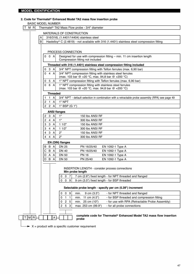
47
MODEL IDENTIFICATION
2. Code for Thermatel® Enhanced Model TA2 mass flow insertion probe
MATERIALS OF CONSTRUCTIONA 316/316L (1.4401/14404) stainless steelB Hastelloy® C (2.4819) - not available with 316 (1.4401) stainless steel compression fitting
T AM R complete code for Thermatel® Enhanced Model TA2 mass flow insertionprobe
T M R Thermatel® TA2 Mass Flow probe - 3/4" diameterBASIC MODEL NUMBER
0 0 7 7 cm (2.6") fixed length - for NPT threaded and flanged0 0 9 9 cm (3.5") fixed length - for BSP threaded
INSERTION LENGTH - consider process connectionsMin probe length
0 0 9 min. 9 cm (3.5") - for NPT threaded and flanged0 1 1 min. 11 cm (4.5") - for BSP threaded and compression fitting0 2 5 min. 25 cm (10") - for use with RPA (Retractable Probe Assembly)2 5 3 max. 253 cm (99.9") - for all probe connections
Selectable probe length - specify per cm (0.39") increment
X = product with a specific customer requirement
0 0 A Designed for use with compression fitting – min. 11 cm insertion lengthCompression fitting not included
PROCESS CONNECTION
0 3 A 3/4" NPT compression fitting with Teflon ferrules (max. 6,90 bar)0 4 A 3/4" NPT compression fitting with stainless steel ferrules
(max. 103 bar @ +20 °C, max. 94,8 bar @ +200 °C)0 5 A 1" NPT compression fitting with Teflon ferrules (max. 6,90 bar)0 6 A 1" NPT compression fitting with stainless steel ferrules
(max. 103 bar @ +20 °C, max. 94,8 bar @ +200 °C)
Threaded with 316 (1.4401) stainless steel compression fitting included
2 3 A 1" 150 lbs ANSI RF2 4 A 1" 300 lbs ANSI RF3 3 A 1 1/2" 150 lbs ANSI RF3 4 A 1 1/2" 300 lbs ANSI RF4 3 A 2" 150 lbs ANSI RF4 4 A 2" 300 lbs ANSI RF
ANSI flanges
B B A DN 25 PN 16/25/40 EN 1092-1 Type AC B A DN 40 PN 16/25/40 EN 1092-1 Type AD A A DN 50 PN 16 EN 1092-1 Type AD B A DN 50 PN 25/40 EN 1092-1 Type A
EN (DIN) flanges
1 1 A 3/4" NPT - default selection in combination with a retractable probe assembly (RPA) see page 492 1 A 1" NPT2 2 A 1" BSP (G 1")
Threaded

48
MODEL IDENTIFICATION
2. Code for Thermatel® Enhanced Model TA2 sensor with flow body
THREADED FLOW BODY - ø size and connection0 1 1/2" NPT1 1 3/4" NPT2 1 1" NPT3 1 11/2" NPT4 1 2" NPT
MATERIALS OF CONSTRUCTIONA 316/316L (1.4401/1.4404) stainless steel body and sensor1 Carbon steel body / stainless steel sensor
FLOW CONDITIONING PLATE
T F T 0 0 0 complete code for Thermatel® Enhanced Model TA2 sensor with flow body
FLANGED FLOW BODY - ø size and connection0 3 1/2" 150 lbs ANSI RF1 3 3/4" 150 lbs ANSI RF2 3 1" 150 lbs ANSI RF3 3 11/2" 150 lbs ANSI RF4 3 2" 150 lbs ANSI RF5 3 3" 150 lbs ANSI RF6 3 4" 150 lbs ANSI RF
T F T Thermatel® TA2 sensor with mass flow body
A NoneB Stainless steel flow conditioning plate - For flow body sizes ≥ 11/2"
BASIC MODEL NUMBER
X = product with a specific customer requirement
3. Code for connecting cable remote mount Thermatel® Enhanced Model TA2 mass flow meter
0 complete code for connecting cable
0 0 3 min 3 m (9.84 ft) length0 6 0 max 60 m (196 ft) length (for 037-3314-xxx cable)1 5 0 max 150 m (492 ft) length (for 037-3320-xxx and 009-8270-xxx cable)
CABLE LENGTH - specify per m (3.28 ft) increment
0 3 7 – 3 3 1 4 Connecting cable for non-hazardous area - 8 wire shielded instrument cable (max 60 m)0 3 7 – 3 3 2 0 Connecting cable for non-hazardous area - 10 wire shielded instrument cable (max 150 m)0 0 9 – 8 2 7 0 Connecting cable for ATEX flameproof enclosure - 8 wire shielded instrument cable (max 150 m)

49
MODEL IDENTIFICATION
4. Code for other options
3/4" NPTconnection
Ø 152,4(6.00)
Duct mounting bracket with 3⁄4" NPTcode 089-7247-001 or
089-7247-002 (includes mounting hardware)
4. Code for retractable probe assembly
MATERIALS OF CONSTRUCTION
PROCESS CONNECTION0 1 1/2" NPT – not available for RPA-E11 1 1/2" - 150 lbs RF flange2 1 1/2" - 300 lbs RF flange
1 Carbon steel with 316 SST (1.4401) seal gland4 316 SST (1.4401)
DESIGN TYPEE Low pressure - up to 5,5 bar (80 psi)F High pressure - up to 300 lbs service
BALL VALVE
R P A complete code for retractable probe assembly
R P A Retractable probe assembly
0 No ball valve supplied1 Carbon steel ball valve – select material code 12 Stainless steel ball valve – select material code 4
BASIC MODEL NUMBER
0 2 5 min 25 cm (9.84")1 8 0 max 180 cm (70.87")
PROBE LENGTH
X = product with a specific customer requirement
When ordered separately:
ProcessConn. Size
Compression fitting in 316 (1.4401) stainless steelTeflon ferrules
Max. 6,90 bar (100 psi)Stainless steel ferrules
Max. 103 bar @ +20 °C (1500 psi @ +70 °F)Max. 94,8 bar @ +200 °C (1375 psi @ +400 °F)
1" NPT code: 011-4719-009 code: 011-4719-0073/4" NPT code: 011-4719-008 code: 011-4719-006
1" NPT ball valve in 316 SST withcompression fitting (TFE ferrules)
code: 089-5218-001
203 (8) Typical1" NPTcustomersupplied
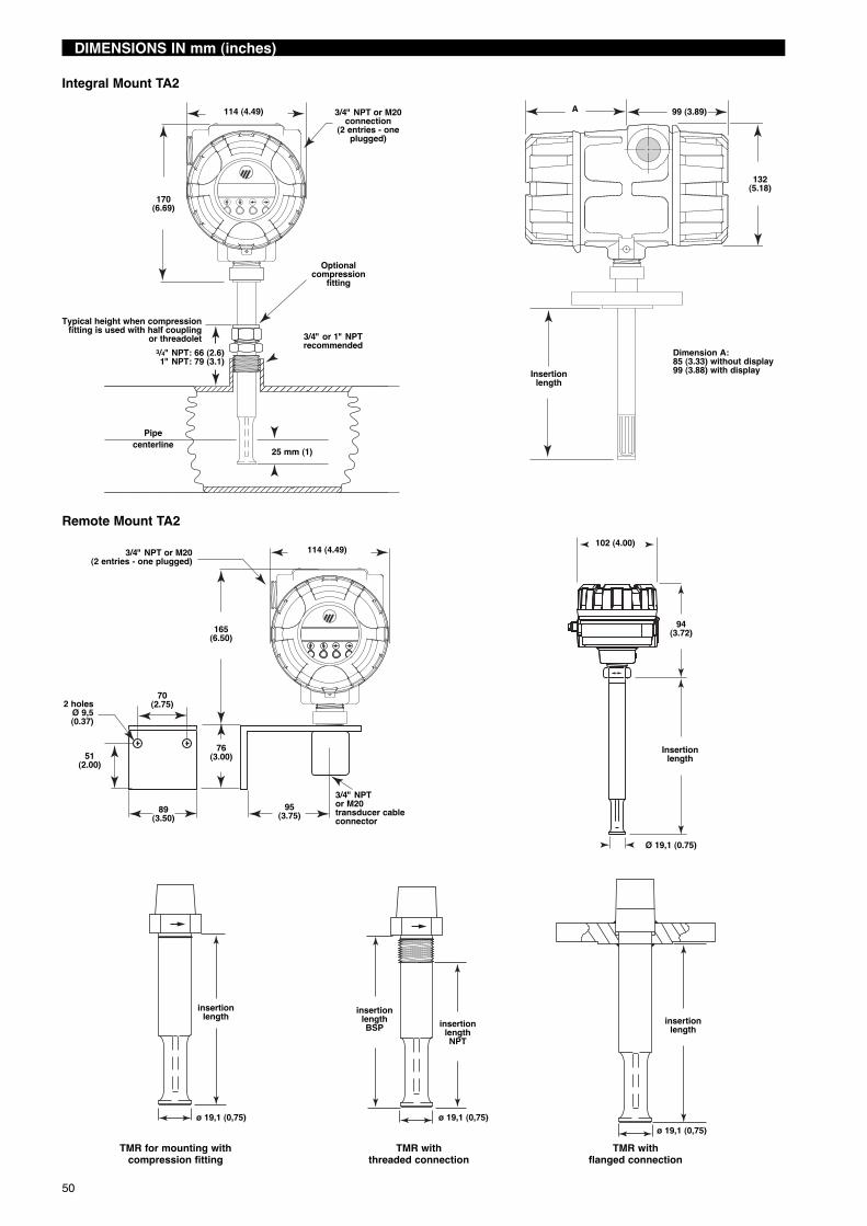
50
DIMENSIONS IN mm (inches)
insertionlength
ø 19,1 (0,75)
TMR for mounting withcompression fitting
insertionlengthNPT
insertionlengthBSP
ø 19,1 (0,75)
TMR withthreaded connection
insertionlength
ø 19,1 (0,75)TMR with
flanged connection
114 (4.49) 99 (3.89)
170(6.69)
A3/4" NPT or M20connection
(2 entries - oneplugged)
132(5.18)
Insertionlength
3/4" or 1" NPTrecommended
Pipecenterline 25 mm (1)
Optionalcompression
fitting
3/4" NPT: 66 (2.6)1" NPT: 79 (3.1)
Typical height when compressionfitting is used with half coupling
or threadoletDimension A:85 (3.33) without display99 (3.88) with display
Integral Mount TA2
Remote Mount TA2114 (4.49) 102 (4.00)
3/4" NPT or M20(2 entries - one plugged)
Ø 19,1 (0.75)
165(6.50)
70(2.75)
94(3.72)
Insertionlength
2 holesØ 9,5(0.37)
76(3.00)
89(3.50)
95(3.75)
51(2.00)
3/4" NPTor M20transducer cableconnector

51
DIMENSIONS IN mm (inches)
Ball Valve Dimensions*Size V11⁄2" NPT 112 (4.4)11⁄2" 150# flange 165 (6.5)11⁄2" 300# flange 191 (7.5)
*Dimension of ball valve if supplied by the factory.
S DimensionThreaded connection 102 (4.00)Flanged connection 127 (5.00)
B
A BA
L
L1
L1
L
Code Size
Length (L) L1 Height toCenterline
(A)mm (inches)
Overall Height (B)
With FlowConditioningmm (inches)
Without FlowConditioningmm (inches)
With FlowConditioningmm (inches)
Without FlowConditioningmm (inches)
NPT-Fmm (inches)
Flangemm (inches)
0 1/2" 203 (8)� — 127 (5)� — 203 (8.0) 214 (8.4) 248 (9.7)
1 3/4" 286 (11.25)� — 191 (7.5)� — 203 (8.0) 217 (8.5) 251 (9.9)
2 1" 381 (15)� — 254 (10)� — 203 (8.0) 220 (8.7) 257 (10.1)
3 11/2" 495 (19.5) 191 (7.5) 305 (12) 95 (3.75) 211 (8.3) 235 (9.3) 274 (10.8)
4 2" 660 (26) 191 (7.5) 406 (16) 95 (3.75) 241 (9.5) 272 (10.7) 318 (12.5)
5 3" 991 (39) 254 (10) 610 (24) 127 (5) 241 (9.5) N/A 337 (13.3)
6 4" 1321 (52) 305 (12) 914 (36) 152 (6) 241 (9.5) N/A 356 (14.0)
Flanged flow body Threaded flow body
� The upstream length in pipe sizes < 1 1/2" dia. is sufficient to create the flow conditioning effect without need for a flow conditioning plate.
Flowconditioning
plate
Y
S
XV
T
X
Y
V
Adjustmentrods
Adjustmentnuts
Retaining bar Safety cable
Seal nut
1 1/2" NPT
Ball valve
Vessel wall
Seal nut
Ball valve
25 (1)
Vessel wall
Pipe centerline
25 (1)Pipe centerline
Customerconnection
Customerconnection
Model RPA-F412-XXX
minimum probe length: T = 2 (X + Y)
Model RPA-E402-XXX
minimum probe length: S + X + Y
IMPORTANT
SERVICE POLICY
Owners of Magnetrol products may request the return of a control; or, any part of a control for complete rebuilding orreplacement. They will be rebuilt or replaced promptly. Magnetrol International will repair or replace the control, at no cost tothe purchaser, (or owner) other than transportation cost if:
a. Returned within the warranty period; and,b. The factory inspection finds the cause of the malfunction to be defective material or workmanship.
If the trouble is the result of conditions beyond our control; or, is NOT covered by the warranty, there will be charges for labourand the parts required to rebuild or replace the equipment.In some cases, it may be expedient to ship replacement parts; or, in extreme cases a complete new control, to replace theoriginal equipment before it is returned. If this is desired, notify the factory of both the model and serial numbers of thecontrol to be replaced. In such cases, credit for the materials returned, will be determined on the basis of the applicability ofour warranty.No claims for misapplication, labour, direct or consequential damage will be allowed.
RETURNED MATERIAL PROCEDURE
So that we may efficiently process any materials that are returned, it is essential that a “Return Material Authorisation” (RMA)form will be obtained from the factory. It is mandatory that this form will be attached to each material returned. This form isavailable through Magnetrolʼs local representative or by contacting the factory. Please supply the following information:
1. Purchaser Name2. Description of Material3. Serial Number and Ref Number4. Desired Action5. Reason for Return6. Process details
Any unit that was used in a process must be properly cleaned in accordance with the proper health and safety standardsapplicable by the owner, before it is returned to the factory.A material Safety Data Sheet (MSDS) must be attached at the outside of the transport crate or box.All shipments returned to the factory must be by prepaid transportation. Magnetrol will not accept collect shipments.All replacements will be shipped Ex Works.
www.magnetrol.com
BENELUX Heikensstraat 6, 9240 Zele, België -BelgiqueFRANCE Tel. +32 (0)52.45.11.11 • Fax. +32 (0)52.45.09.93 • E-Mail: [email protected] Alte Ziegelei 2-4, D-51491 Overath Tel. +49 (0)2204 / 9536-0 • Fax. +49 (0)2204 / 9536-53 • E-Mail: [email protected] C-20 Community Centre, Janakpuri, New Delhi - 110 058
Tel. +91 (11) 41661840 • Fax +91 (11) 41661843 • E-Mail: [email protected] Via Arese 12, I-20159 Milano
Tel. +39 02 607.22.98 • Fax. +39 02 668.66.52 • E-Mail: [email protected]. DAFZA Office 5EA 722 • PO Box 293671 • Dubai Tel. +971-4-6091735 • Fax +971-4-6091736 • E-Mail: [email protected] Unit 1 Regent Business Centre, Jubilee Road Burgess Hill West Sussex RH 15 9TLKINGDOM Tel. +44 (0)1444 871313 • Fax +44 (0)1444 871317 • E-Mail: [email protected]
BULLETIN N°: BE 54-631.0EFFECTIVE: March 2011SUPERSEDES: NewUNDER RESERVE OF MODIFICATIONS