Embed Size (px)
Citation preview

Thermal testing of LEDs:
emerging standards
András Poppe, PhD
Mentor Graphics MicReD Division, Budapest, Hungary

2 © 2011 Mentor Graphics Corporation
www.mentor.com/micred
A. Poppe: Thermal testing of LEDs - emerging standards
21 March 2011 / MEPTEC "The heat is on" Symposium
Why to deal with thermal issues in case of LEDs?
Reliability is connected to thermal issues — life time (failure mechanisms are thermally assisted) — mechanical stress
Optical properties strongly depend on temperature — spectra — emitted flux / efficiency / efficacy
0
500
1000
1500
2000
2500
3000
3500
4000
4500
5000
560 570 580 589 599 609 619 629 639 649 659 669 678 688
[nm]
Spectral power distribution [µW/nm] 20 oC
30 oC
40 oC
50 oC
60 oC
70 oC
IF = 300 mA
698
No doubt that reliable thermal data is a must for
power LEDs: widely accepted standards are
needed

3 © 2011 Mentor Graphics Corporation
www.mentor.com/micred
A. Poppe: Thermal testing of LEDs - emerging standards
21 March 2011 / MEPTEC "The heat is on" Symposium
Standardization status at CIE (from Y. Ohno)

4 © 2011 Mentor Graphics Corporation
www.mentor.com/micred
A. Poppe: Thermal testing of LEDs - emerging standards
21 March 2011 / MEPTEC "The heat is on" Symposium
Overview document (not yet accepted)
Each box represents recommendations for a particular problem. — New modules can be easily added
Approach of the JEDEC JC15 committee
Measurement
of AC LEDs
Measurement
of Rth during
LM80 tests
OVERVIEW
THERMAL MEASUREMENT
THERMAL ENVIRONMENT
COMPONENT MOUNTING
COMPONENT CONSTRUCTION
APPLICATION GUIDELINES
Electrical Test
Method
Guideline for
Estimation
Measurements
(as proposed
by NIST)
Additional
thermal
guidelines for
IESNA LM80
tests
???
???
???
MODELING
Model
validation
procedures Guideline for
combining CIE
127-2007
measurements
with thermal
measurements
Natural
Convection
Heat Sink
Forced
Convection
Heat Sink
Mounting
Thermal Test
Board
Test
Luminaires
Single Light
Source LED
Multi-Light
Source LED
Terms,
Definitions &
Units Glossary
???
Dynamic Compact
Thermal Model for
single light source
single heat-flow
path LEDs
??? Drafts
Issue identified which is dealt with
Recently identified issue which is dealt with
Yet to be identified and/or to be dealt with
JEDEC JC15 committee
actively works on these:
Today we
shall cover
these

5 © 2011 Mentor Graphics Corporation
www.mentor.com/micred
A. Poppe: Thermal testing of LEDs - emerging standards
21 March 2011 / MEPTEC "The heat is on" Symposium
A few words about thermal resistance of LEDs
Original definition in the JEDEC JESD51-1 document
Classically, for Si semiconductor diodes: Rth-el = ΔTJ / (IF×VF)
Accurate; the questions are: — what is the dissipated power of an LED? Subtract radiant flux
— what is the TX reference temperature Use cold plate!
For LEDs, consider the radiant flux: Rth-r = ΔTJ / (IF×VF – Popt)
Both Rth-el and Rth-r are correct, if proper power is used to calculate TJ

6 © 2011 Mentor Graphics Corporation
www.mentor.com/micred
A. Poppe: Thermal testing of LEDs - emerging standards
21 March 2011 / MEPTEC "The heat is on" Symposium
Importance of the definition of Rth for LEDs
Traditionally: Rth-el = TJ / Pel = TJ / (IF VF)
Due to high efficiency, radiant flux must be considered:
Rth-r = TJ / (Pel – Popt)
= TJ / (IF VF – Popt)
By neglecting Popt vendors report
much nicer data than reality
ηe = Popt/Pel (radiant efficiency)
EXAMPLE: Let us assume two ηe -s
T = 50oC, Pel = 10W
— ηe =0% (electrical only) "Rth-el" = T / Pel = 50/10 = 5 K/W
— ηe = 25%
Rth-r = T / (Pel – Popt) = T / [Pel (1-ηe)] = = 50/(100.75) = 6.67 K/W
— ηe = 50%
Rth-r = T / (Pel – Popt) = T / [Pel 1-ηe)] = = 50/(100.5) = 10 K/W

7 © 2011 Mentor Graphics Corporation
www.mentor.com/micred
A. Poppe: Thermal testing of LEDs - emerging standards
21 March 2011 / MEPTEC "The heat is on" Symposium
Junction temperature – performance indicator
Calculation: TJ = RthJ-X PH + TX — RthJ-X junction-to-reference_X thermal resistance supplied by the LED
vendor
— PH heating power measured/calculated by the LED user – How?
— TX reference temperature (un)specified by the LED user
Used in the design process to decide if the foreseen cooling is sufficient or not… — Not enough: in case of LEDs, prediction of ―hot lumens‖ is also required
TJ
t
TJ1
TJ2
TJ
PH1
PH2
t
PH
PH
H
J
XthJP
TR
)(
Differential formulation of the thermal resistance
H
XJ
H
XJXthJ
P
T
P
TTR
][
Instead of spatial difference (temperature values at
junction and reference point) temporal difference of the
junction temperature can be used
8 © 2011 Mentor Graphics Corporation
www.mentor.com/micred
A. Poppe: Thermal testing of LEDs - emerging standards
21 March 2011 / MEPTEC "The heat is on" Symposium
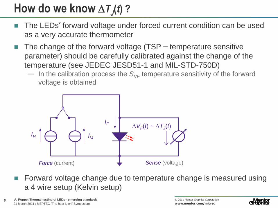
How do we know TJ(t) ?
The LEDs’ forward voltage under forced current condition can be used
as a very accurate thermometer
The change of the forward voltage (TSP – temperature sensitive
parameter) should be carefully calibrated against the change of the
temperature (see JEDEC JESD51-1 and MIL-STD-750D) — In the calibration process the SVF temperature sensitivity of the forward
voltage is obtained
Forward voltage change due to temperature change is measured using
a 4 wire setup (Kelvin setup)
IF VF(t) ~ TJ(t)
IM IH
Force (current) Sense (voltage)

9 © 2011 Mentor Graphics Corporation
www.mentor.com/micred
A. Poppe: Thermal testing of LEDs - emerging standards
21 March 2011 / MEPTEC "The heat is on" Symposium
The measurement waveforms
tMD
t
t=0
VF
IH
IM
VH
VF
IF
tH tM
heating
measurement
t
topt
VFf
VFi
cooling stable
Time window for the CIE 127-2007 compliant measurement of the light output

10 © 2011 Mentor Graphics Corporation
www.mentor.com/micred
A. Poppe: Thermal testing of LEDs - emerging standards
21 March 2011 / MEPTEC "The heat is on" Symposium
Comprehensive LED testing solution:
Popt(T,IF)
ηe(T,IF)
V(T,IF)
photometric/radiometric
measurements in thermal
steady-state
JEDEC JSD51-1 static test method compliant thermal measurement system
CIE 127-2007 compliant photometric & radiometric measurement system
steady-state
electrical
powering
thermal resistance/impedance
measurement
IM IH
Force
(current)
VF(t)
~
TJ(t)
Sense
(voltage)
IF V
F
Temp.controlled
heat sink
Detector
Aux. LED
Test LED
IF
Integrating
sphere
Thermal
test
equipment
switching-off
from IH to IM
calculate Rth-r and TJ
The JEDEC JC15 committee deals with these issues. A set of documents is prepared and is being discussed (how to apply JESD51-1 & CIE 127-2007)
11 © 2011 Mentor Graphics Corporation
www.mentor.com/micred
A. Poppe: Thermal testing of LEDs - emerging standards
21 March 2011 / MEPTEC "The heat is on" Symposium
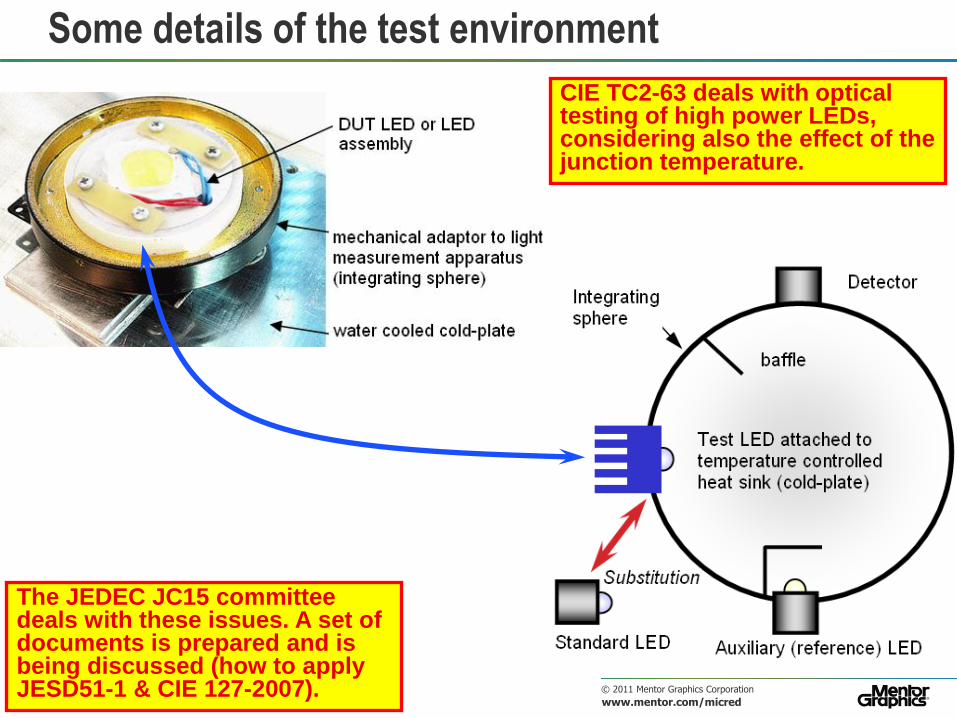
Some details of the test environment
The JEDEC JC15 committee deals with these issues. A set of documents is prepared and is being discussed (how to apply JESD51-1 & CIE 127-2007).
CIE TC2-63 deals with optical testing of high power LEDs, considering also the effect of the junction temperature.

12 © 2011 Mentor Graphics Corporation
www.mentor.com/micred
A. Poppe: Thermal testing of LEDs - emerging standards
21 March 2011 / MEPTEC "The heat is on" Symposium
The Mentor Graphics MicReD implementation:
photo-
detector
V(), Xlong, Xshort, Z and flat response filters in a filter bank
DUT LED on TEC cooled
stage
control electronics
thermal transient
tester equipment
reference LED
It can be added to the system in a plug&play manner if the voltage of the base tester is not sufficient.
Special LED booster: allows high voltage across a LED line (overall forward
voltage can reach 280V – needed for AC mains driven LEDs).

13 © 2011 Mentor Graphics Corporation
www.mentor.com/micred
A. Poppe: Thermal testing of LEDs - emerging standards
21 March 2011 / MEPTEC "The heat is on" Symposium
What temperature to report?
The same luminous flux measurement results shown as function of
reference temperature and junction temperature
20 40 60 80 100 120 0
50
100
150
200
250
TJ [oC]
ΦV [lm] TERALED: Luminous Flux vs Junction Temperature
IF = 150mA IF = 200mA IF = 350mA IF = 500mA IF = 700mA
10 20 30 40 50 60 70 80 90 0
50
100
150
200
250
TERALED: Luminous Flux vs Reference Temperature
Tref [oC]
ΦV [lm]
IF = 150mA IF = 200mA IF = 350mA IF = 500mA IF = 700mA
The junction temperature is the
one which determines the light
output, this is the relevant
quantity.
The JEDEC JC15 committee deals with these issues. A set of documents is prepared and is being discussed (how to apply JESD51-1 & CIE 127-2007)

Case study: 10W white LEDs with their thermal
properties and light output characteristics as function of forward current and junction
temperature

15 © 2011 Mentor Graphics Corporation
www.mentor.com/micred
A. Poppe: Thermal testing of LEDs - emerging standards
21 March 2011 / MEPTEC "The heat is on" Symposium
Measured at 700 mA and 85 oC
— Structure functions of 3 samples, power corrected with Popt
— RthJC is identified in a way similar to the transient double interface method, a
new standard: JEDEC JESD51-14
FSF52 AL TG2500
RthJC real ≈ 2 K/W
Results for 10W white LEDs
16 © 2011 Mentor Graphics Corporation
www.mentor.com/micred
A. Poppe: Thermal testing of LEDs - emerging standards
21 March 2011 / MEPTEC "The heat is on" Symposium
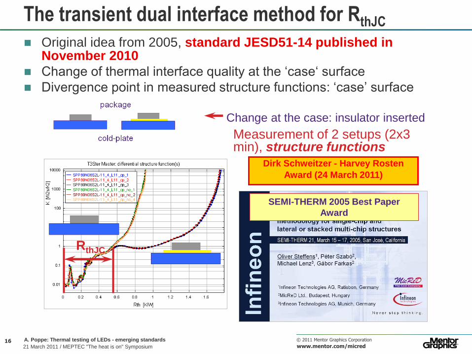
The transient dual interface method for RthJC
Original idea from 2005, standard JESD51-14 published in November 2010
Change of thermal interface quality at the ‘case‘ surface
Divergence point in measured structure functions: ‘case’ surface
Change at the case: insulator inserted
Measurement of 2 setups (2x3 min), structure functions
RthJC
SEMI-THERM 2005 Best Paper
Award
Dirk Schweitzer - Harvey Rosten
Award (24 March 2011)
17 © 2011 Mentor Graphics Corporation
www.mentor.com/micred
A. Poppe: Thermal testing of LEDs - emerging standards
21 March 2011 / MEPTEC "The heat is on" Symposium
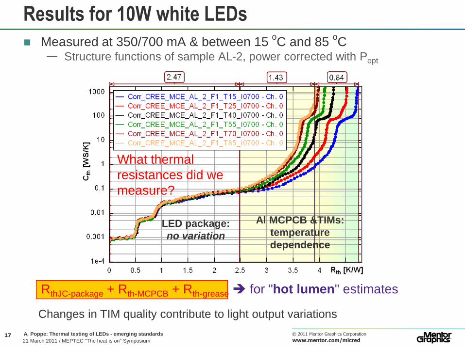
Results for 10W white LEDs
Measured at 350/700 mA & between 15 oC and 85
oC
— Structure functions of sample AL-2, power corrected with Popt
LED package:
no variation
Al MCPCB &TIMs:
temperature
dependence
What thermal
resistances did we
measure?
RthJC-package + Rth-MCPCB + Rth-grease for "hot lumen" estimates
Changes in TIM quality contribute to light output variations

18 © 2011 Mentor Graphics Corporation
www.mentor.com/micred
A. Poppe: Thermal testing of LEDs - emerging standards
21 March 2011 / MEPTEC "The heat is on" Symposium
ΦV(Tref) plots for two cases (IF=350mA)
360
370
380
390
400
410
420
430
440
450
10 20 30 40 50 60 70 80 90
Lum
inous F
lux [lm
]
Tref [degC]
Cree MCE1 Luminous Fluxes at 350mA as function of Tref
'FSF52'
'TG2500-1'
Variation of Rth means, the device
characteristics scaled in reference
temperature will be different 360
370
380
390
400
410
420
430
440
450
20 30 40 50 60 70 80 90 100 110
Lum
inous F
lux [lm
]
Tj [degC]
Cree MCE1 Luminous Fluxes at 350mA as function of Tj
'FSF52'
'TG2500-1'
TJ = Tref + Rth-r (IF VF - Popt)
Re-scaling for junction temperature eliminates the
effect of the different thermal resistance values
No need for a sophisticated control
of the TEC in the integrated sphere

Further problems: Thermal issues in short-pulse testing
and in LM80 tests, AC LEDs

20 © 2011 Mentor Graphics Corporation
www.mentor.com/micred
A. Poppe: Thermal testing of LEDs - emerging standards
21 March 2011 / MEPTEC "The heat is on" Symposium 4 August 2010
Short pulse measurements
During in-line testing photometric/colorimetric properties are measured
with a short pulse — TJ = Tref = constant is assumed, THIS IS NOT TRUE:
In 10 ms significant junction temperature change may take place
During 10 ms TJ changes almost by 5
oC
1e-6 1e-4 0.01 1 100 10000
0
5
10
15
20
25
Time [s]
Norm
aliz
ed
te
mp
era
ture
ris
e [°
C]
T3Ster Master: Zth
dimco_kisf2 - Ch. 0
Question is if this causes big problems or not…
1W white LED measured in free
air without any cooling
assembly
Addressed by CIE TC 2-64

21 © 2011 Mentor Graphics Corporation
www.mentor.com/micred
A. Poppe: Thermal testing of LEDs - emerging standards
21 March 2011 / MEPTEC "The heat is on" Symposium 4 August 2010
Example: 10W white LED
Pheat 3W @ 350mA
Rth-r 20K/W
1e-6 1e-5 1e-4 0.001 0.01 0.1 1 10 100 1000 0
20
40
60
80
100
120
140
Time [s]
Tem
pe
ratu
re r
ise [°
C]
Junction Temperature Response 0.01
15.0
15.3
Cree_MCE1_T25_2_F1_T25_I0350 - Ch. 0
Cree_MCE1_T25_2_F1_T25_I0700 - Ch. 0
TJ +15oC IF=350 mA
TJ +30oC IF=700 mA
t = 10 ms
15 20 25 30 35 40 5800
5900
6000
6100
6200
6300
T [°C]
CC
T [
K]
TCC vs. Temperature 15
22.80
48.53 IF = 350mA IF = 700mA
TCC+22 K for TJ=15 oC @ 350 mA
TCC+50 K for TJ=15 oC @ 700 mA
T = 15 oC
24 26 28 30 32 34 36 38 40
350
400
450
500
550
600
650
700
750
800
T [°C]
V [lm] Luminous Flux vs. Temperature 15
18.2
IF = 350mA IF = 700mA
V -18 lm for TJ=15 oC @ 350 mA
Slope -1.2 lm/oC
T = 15 oC Addressed by CIE TC 2-64

22 © 2011 Mentor Graphics Corporation
www.mentor.com/micred
A. Poppe: Thermal testing of LEDs - emerging standards
21 March 2011 / MEPTEC "The heat is on" Symposium
LM80 test chamber
with all the LEDs
assembled
In-situ light output
measurement
In-situ thermal transient
measurement All measurements are done in-situ to eliminate any Rth change which is NOT due to ageing
In-situ thermal measurements during LM80 tests

23 © 2011 Mentor Graphics Corporation
www.mentor.com/micred
A. Poppe: Thermal testing of LEDs - emerging standards
21 March 2011 / MEPTEC "The heat is on" Symposium
4.Osram LUWV5AM 350mA
85%
90%
95%
100%
105%
110%
0 200 400 600 800 1000 1200
41
42
43
44
45
46
aver.
Structure functions taken at
0h, 500h, 1000h
Relative Luminous Flux (Vendor O, IF = 350 mA)
Time [h]
sample #
In cooperation with University of Pannonia, Veszprém (Hungary), prof. J. Schanda’s group within the KöZLED project of the Hungarian Goverment
8 different kinds of LEDs from 4 vendors, so far 6500h burning time,
processing measurement data in progress
No change inside
the LED package
Ligh output drop likely due
to increased Rth caused by
TIM degradation, not by
LED degradation
Recent results from LM80 test of different LEDs

24 © 2011 Mentor Graphics Corporation
www.mentor.com/micred
A. Poppe: Thermal testing of LEDs - emerging standards
21 March 2011 / MEPTEC "The heat is on" Symposium
Results after 3000h:
All HK LEDs have already died
Recent results from LM80 test of different LEDs
0 2 4 6 8 10 12
1e-5
1e-4
0.001
0.01
0.1
1
10
100
Rth [K/W]
Cth
[W
s/K
] T3Ster Master: cumulative structure function(s)
15.1
Vendor O, sample #44, 0h
Vendor O, sample #44, 3000h
Vendor O, sample #44, 2000h
Vendor O, sample #44, 500h
0.9
With real values of dVF/dT
0 2 4 6 8
5.6 4.7 0.6
1e-5
1e-4
0.001
0.01
0.1
1
10
100
Cth
[W
s/K
] T3Ster Master: cumulative structure function(s)
Rth [K/W]
TIM ageing: external to the
LED – LM80 measurement
results must be compensated
for this
Delemination from the MCPCB: a failure inside the
LED assembly, its contribution to light output
degradation is part of the LM80 test result
Vendor HK, sample #61, 0h Vendor HK, sample #61, 500h
Vendor HK, sample #61, 2000h Vendor HK, sample #61, 3000h
With real values of dVF/dT

25 © 2011 Mentor Graphics Corporation
www.mentor.com/micred
A. Poppe: Thermal testing of LEDs - emerging standards
21 March 2011 / MEPTEC "The heat is on" Symposium
Problems of testing AC LEDs: what “Zth” to use?
For AC LEDs instead of the classical time-domain representation of Zth we need its frequency domain representation
At higher frequency the absolute value of
Zth(ω) is smaller:
0
)(1
)( dtetaP
Z tj
dissDC
th
asscoolingthth
th
th
th
th
th
th ZRCj
RCj
RCj
Z _3
3
2
2
1
1
111)(
26 © 2011 Mentor Graphics Corporation
www.mentor.com/micred
A. Poppe: Thermal testing of LEDs - emerging standards
21 March 2011 / MEPTEC "The heat is on" Symposium
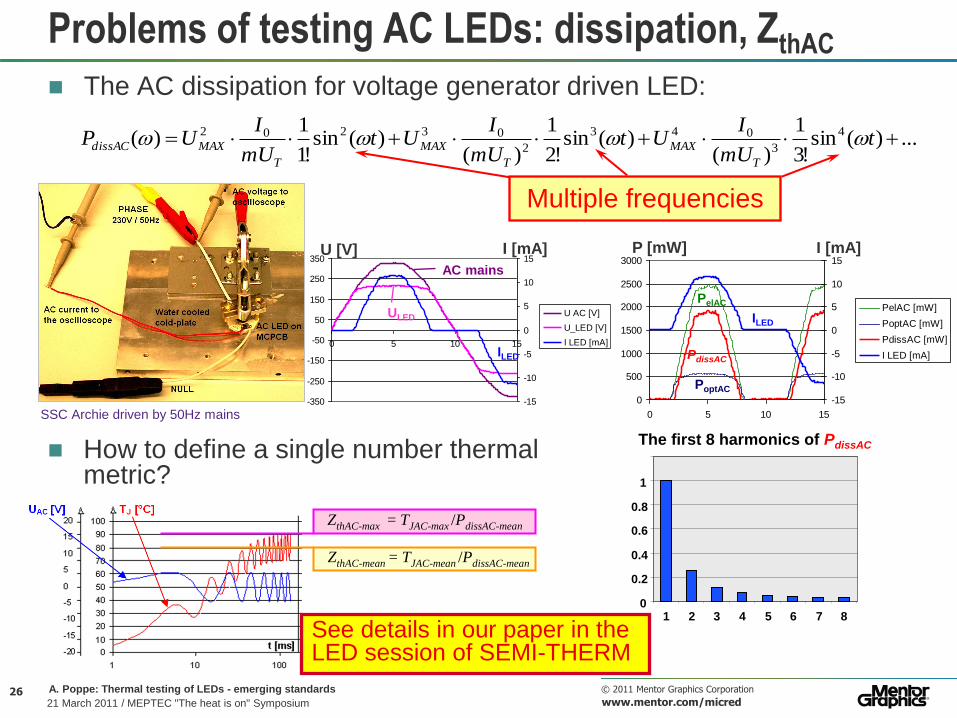
Problems of testing AC LEDs: dissipation, ZthAC
The AC dissipation for voltage generator driven LED:
...)(sin!3
1
)()(sin
!2
1
)()(sin
!1
1)( 4
3
043
2
03202 tmU
IUt
mU
IUt
mU
IUP
T
MAX
T
MAX
T
MAXdissAC
SSC Archie driven by 50Hz mains -350
-250
-150
-50
50
150
250
350
0 5 10 15
-15
-10
-5
0
5
10
15
U AC [V]
U_LED [V]
I LED [mA]
U [V] I [mA]
AC mains
ULED
ILED
0
500
1000
1500
2000
2500
3000
0 5 10 15
-15
-10
-5
0
5
10
15
PelAC [mW]
PoptAC [mW]
PdissAC [mW]
I LED [mA]
0
0.2
0.4
0.6
0.8
1
1 2 3 4 5 6 7 8
The first 8 harmonics of PdissAC
P [mW] I [mA]
ILED
PelAC
PdissAC
PoptAC
Multiple frequencies
How to define a single number thermal metric?
ZthAC-max = TJAC-max /PdissAC-mean
ZthAC-mean = TJAC-mean /PdissAC-mean
See details in our paper in the LED session of SEMI-THERM

27 © 2011 Mentor Graphics Corporation
www.mentor.com/micred
A. Poppe: Thermal testing of LEDs - emerging standards
21 March 2011 / MEPTEC "The heat is on" Symposium 4 August 2010
Conclusions
Brief overview of standardization needs and recent activities was given
Measurement setup for consistent measurement of thermal and light output metrics of power LEDs was shown
— Based on existing standards (JEDEC JESD51-1, CIE 127-2007)
— Therefore with some new measurement guidelines it is easily implemented
– Such guidelines are being developed by the JEDEC JC15 Committee on Thermal Standards of Packaged Semiconductor Devices
Merits of such a combined thermal/radiometric LED testing station were shown by a case study
— Importance of changing properties of thermal interface materials and their effect on light output was shown
Combined thermal transient and photometric measurements suggest that the constant junction temperature assumption in short pulse in-line testing is not valid
To eliminate effect of variations (ageing) of TIM during LM80 tests, in-situ measurements are suggested, combined with thermal transient measurements
Problems related to the ―AC thermal impedance‖ as a single number thermal metric for AC mains driven LEDs were raised
![Haptic Texture Modeling Using Photometric Stereo · 2020. 7. 14. · B. Photometric Stereo Algorithm We use the photometric stereo algorithm presented in [10] to construct the height](https://img.pdfslide.us/doc/110x75/610118fcbfa54e55cf05e413/haptic-texture-modeling-using-photometric-stereo-2020-7-14-b-photometric-stereo.jpg)

![1. Photometric Stereo, Specularity Removal [15 pts] · 2019-05-16 · 1a. Photometric Stereo [10 pts] Implement the photometric stereo technique described in the lecture slides and](https://img.pdfslide.us/doc/110x75/5f30968f346ec33edc4d682d/1-photometric-stereo-specularity-removal-15-pts-2019-05-16-1a-photometric.jpg)


![Photometric Stereo - Yonsei · 2014. 12. 29. · Photometric Stereo v.s. Structure from Shading [1] • Photometric stereo is a technique in computer vision for estimating the surface](https://img.pdfslide.us/doc/110x75/610118fcbfa54e55cf05e412/photometric-stereo-yonsei-2014-12-29-photometric-stereo-vs-structure-from.jpg)