Embed Size (px)
Citation preview

THERMAL STRESSES AND RELATED FAILURE MECHANISMS: BRIDGE-WIRE INITIATORS
Final Report
KLK414
N08-16
National Institute for Advanced Transportation Technology
University of Idaho
Michael R. Maughan, Robert R. Stephens, Donald M.
Blackketter, and Karl K. Rink
August 2008
DISCLAIMER
The contents of this report reflect the views of the authors,
who are responsible for the facts and the accuracy of the
information presented herein. This document is disseminated
under the sponsorship of the Department of Transportation,
University Transportation Centers Program, in the interest of
information exchange. The U.S. Government assumes no
liability for the contents or use thereof.
1. Report No. 2. Government Accession No.
3. Recipient’s Catalog No.
4. Title and Subtitle
5. Thermal Stresses and Related Failure Mechanisms: Bridge-Wire Initiators
6. Report Date August 2008
7. Performing Organization Code KLK414
8. Author(s) Maughan, M. R., Stephens, R. R., Blackketter, D. M., and K. K. Rink
9. Performing Organization Report No. N08-16
10. Performing Organization Name and Address 11. Work Unit No. (TRAIS)
National Institute for Advanced Transportation Technology University of Idaho PO Box 440901; 115 Engineering Physics Building Moscow, ID 83844-0901
12. Contract or Grant No. DTRS98-G-0027
13. Sponsoring Agency Name and Address
US Department of Transportation Research and Special Programs Administration 400 7th Street SW Washington, DC 20509-0001
14. Type of Report and Period Covered Final Report: August 2006 – August 2008
15. Sponsoring Agency Code USDOT/RSPA/DIR-1
16. Supplementary Notes:
17. Abstract
Cracks of the cylindrical glass-to-metal seals (GTMS) of pyrotechnic bridge-wire initiators could present a path for moist gases to diffuse into the critical interior region of the initiator, potentially leading to wire degradation, delayed ignition, or a no-fire condition. The goal of this research is to determine if welding the initiator output can onto the initiator header assembly could produce thermal stresses in the glass sufficient to cause cracking of the GTMS. A finite element analysis (FEA) solution is used to model the transient heat transfer and temperature distribution in the initiator assembly during the welding process. The thermal stresses are calculated using a mechanical analysis once the temperature distribution is determined. Compressive stresses induced by pressing the header assembly into the output can are also investigated using a closed-form solution. While predicted thermal stresses are shown to exceed the range of glass strengths reported in the literature, superposition of the compressive stresses due to the press-fit and the residual stresses due to the thermal stresses produced during welding are shown to be on the same order as the reported glass strengths. It is shown that when initiators are overheated during welding, failure of a portion of the pin-glass interface may occur.
18. Key Words
19. Distribution Statement
Unrestricted; Document is available to the public through the National Technical Information Service; Springfield, VT.
20. Security Classif. (of this report)
Unclassified
21. Security Classif. (of this page)
Unclassified
22. No. of Pages
21
23. Price
…
Form DOT F 1700.7 (8-72) Reproduction of completed page authorized
Thermal Stresses i
TABLE OF CONTENTS
INTRODUCTION .................................................................................................................... 1
METHODS ............................................................................................................................... 4
Initiator Description .............................................................................................................. 4
Closed Form Solution ........................................................................................................... 6
Finite Element Analysis ...................................................................................................... 10
RESULTS AND DISCUSSION ............................................................................................. 12
Closed Form Solutions ........................................................................................................ 12
1. Parametric Study ..................................................................................................... 12
2. Closed Form Initiator Manufacturing Models ........................................................ 14
Finite Element Analysis ...................................................................................................... 17
CONCLUSIONS..................................................................................................................... 20
Thermal Stresses 1
INTRODUCTION
Airbags were responsible for saving nearly 17,000 lives between 1975 and 2004 [1]. Currently
about 150 million vehicles in the United States are equipped with airbags, and are expected to
function properly during a long vehicle life span. The pyrotechnic initiator within the airbag is
responsible for deploying the airbag in crash situations. In this particular application, it is of
critical importance that they perform reliably without failure or diminished performance for the
intended service life of the vehicle, usually 15 years [2]. Due to the susceptibility of critical
internal components to corrosion induced by moisture or other contaminants, bridge-wire
initiators are intended to be hermetic and impervious to the surrounding environment.
The integrity of the bridge-wire and its surrounding pyrotechnic charge are critical when
considering the hermetic behavior of initiators. Moisture in the bridge-wire region may lead to
corrosion and degradation of the bridge-wire [3-5] and may also result in degradation of certain
pyrotechnic materials. In addition, it is possible that decomposition of some pyrotechnic
materials in the presence of moisture may exacerbate corrosion of the bridge-wire [6]. Moisture
may be inherent in the material constituents of the device, it may be a product of decomposition
of certain pyrotechnic materials, or it may be introduced through an external leak [7]. When
considering the possibility of leaks, of particular concern is the integrity of glass-to-metal seals
which are a common design attribute of bridge-wire initiators. Studies have shown that these
seals may be found to contain cracks or other flaws [8,9], as can be seen in Figure 1.
Thermal Stresses 2
Figure 1 - Crack in initiator glass-to-metal seal
To better understand some of the technical issues surrounding the importance of the glass-to-
metal seal in bridge-wire initiators, it is informative to review common design characteristics and
certain assembly details of these devices. The basic components of a bridge-wire initiator,
illustrated in Figure 2, include: a pyrotechnic output can, a bridge-wire heating element, a glass-
to-metal seal (GTMS) to isolate the electrical pin, a metal header, and a synthetic over-molding.
There is generally at least one electrode (pin) passing through the header. This electrode is
insulated from the metal base by the glass. A fine bridge-wire, typically about 20 m in diameter
is resistance welded to the interior edge of the pin, with the opposite end of the bridge-wire
welded to the header. Given the application of an appropriate electrical signal, the bridge-wire is
rapidly heated, resulting in ignition of the pyrotechnic charge. Since certain features, such as the
shape of the electrical pins, the geometry of internal glass-to-metal seals, and the design of the
header assembly may differ between different manufacturers, the initiator shown is intended to
be representative of those commonly used in the automotive industry. More design details
concerning initiators for both automotive and aerospace applications can be found elsewhere
[10].
Thermal Stresses 3
Figure 2 - Basic elements of a bridge-wire initiator.
During assembly, the header is pressed into the output can and the entire assembly is held in this
position while the two sub-assemblies are sealed together, usually by welding. At this point, the
initiator is considered sealed and is subjected to a leak test to verify hermetic integrity, and a
properly executed leak detection methodology may reveal a damaged GTMS that may otherwise
allow moist gases from the surrounding environment to traverse along the surface of an electrical
pin and penetrate into the bridge-wire region. It is also conceivable that cracks, fissures, or other
flaws may extend through the GTMS, also permitting gases to diffuse into the bridge-wire
region. The purpose of this paper is to focus on the GTMS with respect to the stresses resulting
from thermal changes during the manufacturing process. Thermal stresses that may be caused by
welding the output can onto the header were not considered in this research; rather, the intent
was to use basic mechanics to explore the possibility of thermal stresses great enough to cause
cracks during GTMS manufacture.
The principal problems of GTMS have long been known. Hull and Burger (1934) [11] outline
two requirements for an effective GTMS:
“(1) The glass must ‘wet’ the metal.
Thermal Stresses 4
(2) The stresses resulting from thermal expansion and contraction must not exceed the tensile
strength of the glass.”
They compared calculated and experimental stresses for an external seal (internal wire, external
glass) loaded by weights and show reasonable agreement between the two.
Borom and Giddings [12] consider a seal similar to Figure 1, but of smaller dimensions than
examined in this work and examine the effects of expansion characteristics of component
materials. Their main assertion is that matching expansion characteristics between pin and glass
serves to improve resistance to fracture.
Kokini [13] uses finite elements to determine non-dimensional stresses in GTMS during large
temperature excursions. He conducts thermal shock tests to establish the strength of sample seals
Lee, Chen, and Hung [14] use the Laplace transform and finite difference methods to determine
the transient response of one-dimensional axisymmetric quasi-static coupled thermoelastic
problems. Similarly, Jane and Lee [15] use finite difference and Laplace transform methods to
describe the thermoelasticty of concentric finite-length cylinders. Their two-dimensional
axisymmetric analysis describes the condition where there is a prescribed surface temperature
and no surface tractions.
METHODS
Initiator Description
There are no standard physical geometries of header assemblies. The geometry shown in Figure
3 is representative of the physical geometries common in the industry and available in sufficient
quantities for testing. The three components of the initiator analyzed in this research were the
pin, made of alloy 52, a 50.5% Ni-Fe alloy; the glass, made of 8061 glass; and the header, made
of 304L stainless steel. The material properties of the components of the initiator are shown in
Table 1. This initiator geometry was selected due to its simplicity of design, as the three elements
are concentric, and its availability in quantities sufficient for testing.
Because actual manufacturing methods of initiators are considered proprietary, two processes
were chosen to model possible methods of manufacturing the initiators. In the first method, the
Thermal Stresses 5
pin, preformed glass, and header are assembled at room temperature, placed in a furnace, heated
above the glass transition point of the glass and cooled to room temperature. The second method
heated the glass above its glass transition point and then poured the molten glass into an
assembly that held the pin and header. Though these two methods are not inclusive of all
manufacturing methods, they are representative and will provide insights into reducing the
possibility of failure.
Figure 3 - Idealized header/electrode/GTMS assembly.
Thermal Stresses 6
Table 1 - Material Properties of Initiator Components
Material Property Alloy 52 [16] 8061 Glass
[17] 304L Stainless Steel
[18]
E, GPa 165.5 70 196.5
.29 .22 .29
, m/m/K 10 9.3 18
, kg/m3 8304 2600 8000
k, W/m/K 14 1 18
cp, J/kg/K 502 737 500
Closed Form Solution
A closed form solution (CFS) was used to determine the basic magnitudes of stress that an
initiator is subjected to during the manufacturing process. The closed form solution was based on
the information presented in [19] and [20]. A two-dimensional solution was used, and involved
the following fundamental assumptions:
Stresses were located in the center of the initiator.
Plane stress conditions existed.
The materials were elastic, isotropic, and homogeneous and had temperature-independent material properties.
Perfect adhesion was present at both the bond between the pin and glass and the bond between the glass and header.
There was no interphase region at either interface.
Any interaction effects among the parameters are negligible and can be ignored (i.e. changing one of the parameters does not change the magnitude of the others).
The closed form solution was used to calculate the changes in dimensions of the components of
the initiator due to the temperature change, using Eq. (1). The interfacial pressures were then
calculated using Eq. (2). Eq. (3) was used to ensure that the surfaces of the cylinders remained in
Thermal Stresses 7
contact throughout the manufacturing process. The magnitudes of the radial and tangential
stresses throughout the initiator were determined with Eq. (4) and Eq. (5), respectively.
t r r T (1)
2 2
2 21 2 1 222 2
11p
a brr p a p b p p
rE b a
(2)
1_ 1_ 1_ 2 _ 2 _ 2_o t p i t pr r (3)
2 2
2 12 21 2 2
2 2r
a b p pp a p b
rrb a
(4)
2 2
2 12 21 2 2
2 2t
a b p pp a p b
rrb a
(5)
The closed form solution was first used for a parametric study to determine the effects of
changing the initiator component dimensions (b of the pin, glass, and header), the elastic moduli
(E of the pin, glass, and header), and the material coefficients of thermal expansion (α of the pin,
glass, and header) [21]. Nine cases were analyzed, while for each case one of the nine
aforementioned values was varied. While one value was varied, the remaining eight were
maintained at values representative of real materials used in initiators. The ranges for the
variables can be seen in Table 2. These ranges were not intended to represent actual initiator
materials, but were chosen to encompass all possible and reasonable materials. The decision was
made to ignore any interaction of properties for several reasons. Most importantly, the effect that
changing one property has on the others was unknown. The intent of the work was to clearly
show how varying the parameters changed the stresses, not to predict failure of different types of
initiators. In addition, investigating interaction effects, such as how changing coefficient of
thermal expansion affects the elastic modulus, was beyond the scope of the work and would
require more resources than were available.
In each of the nine cases, only the minimum and maximum stresses within each component of
the airbag initiator were calculated. These values coincided with the extreme radii of each
component (pin, glass, header). The quantity of different stress values under consideration was
Thermal Stresses 8
also reduced by the mechanics of materials equations: at a boundary, the radial stress must equal
the pressure at that location, and when the inner radius of a cylinder equals zero, the radial and
tangential stresses throughout that component are equal. These simplifications left six different
critical stress values to consider, their locations identified in Figure 4. They are:
the radial stress in the glass at the glass-header (GH) interface, that was equal to
the radial stress in the header at the glass-header interface,
the radial stress in the glass at the pin-glass (PG) interface, that was also equal to
both the radial and tangential stresses throughout the pin,
the tangential stress in the glass at the PG interface,
the tangential stress in the glass at the GH interface,
the tangential stress in the header at the GH interface, and
the tangential stress in the header at the outer surface of the initiator.
Table 2 - Range of varying variables for parametric studies
Case Varying Variable
Range
1 of Pin 5-15 [m/m/K]
2 of Glass 4.65-14 [m/m/K]
3 of Header 9-27 [m/m/K]
4 E of Pin 82.8-248 [GPa]
5 E of Glass 35-105 [GPa]
6 E of Header 98.3-295 [GPa]
7 b of Pin 0.05-0.95 [mm]
8 b of Glass 0.55-3.05 [mm]
9 b of Header 1.05-4.2 [mm]
Thermal Stresses 9
Figure 4- Stress profiles and critical stress locations considered during parametric study.
The closed form solution was also used to analyze two different scenarios of the airbag initiator
undergoing uniform cooling. The first scenario was when all three components of the initiator
were stress-free at a temperature of 467ºC, with the initiator then cooled to 20ºC. This scenario
represented the airbag initiator being assembled in a furnace. The high temperature corresponds
to the glass transition temperature of the glass. The second scenario was when the glass was
stress-free at 467ºC, the pin and header were both stress-free at 20ºC, and the glass was cooled to
20ºC. This scenario represented molten glass being poured into the metal components at room
temperature, and the whole assembly cooling to room temperature. This analysis assumed that
initially the glass was stress-free at its glass transition temperature, 467ºC, and that it was cooled
to room temperature, 20ºC, the temperature where the header and pin were stress-free. For
mathematical analysis, the change in temperature of the header and pin was 0ºC and the change
in temperature of the glass was -447ºC.
The closed form solution resulted in high stresses in the GTMS for the case of pouring molten
glass; these results will be presented in the Results section. Since many assumptions were made
for the closed form solution, a more robust approach was needed that would account for the
effects of transient cooling and the three-dimensional geometry of an initiator. This was done
with finite element analysis (FEA), as presented below.
Thermal Stresses 10
Finite Element Analysis
The assumptions of the closed form analysis neglected the possibility of uneven cooling of the
airbag initiator. The closed form analysis also neglected possible three-dimensional effects, such
as stresses induced by a mismatch of thermal deformation on the ends of the initiator at the
interfaces between metal and glass. A FEA was chosen to further analyze the airbag initiator in
order to account for three-dimensional and transient heat transfer effects. These analyses were
based on the same parameters as the finite element analyses that can be found in Refs. [21] and
[22].
ALGOR-FEMPRO version 13.3 was used for the FEA. The mesh is shown in Figure 5. Material
property values from Table 1 were input into ALGOR. Consistent with the closed form solution,
two manufacturing processes were examined. For each manufacturing process, two types of
models were used. The first model type used a combination of default nodal temperatures,
specified for each material. In addition, the stress-free reference temperatures for the three
different materials were input to the program in order to perform a linear stress analysis. The
second model type established the stress-free reference temperatures and nodal temperatures in
the same manner, but used transient heat transfer to determine the temperature distribution within
the airbag initiator. The temperatures found with both types of models were then used to
determine the state of stress within the airbag initiator as the temperatures changed with time.
Thermal Stresses 11
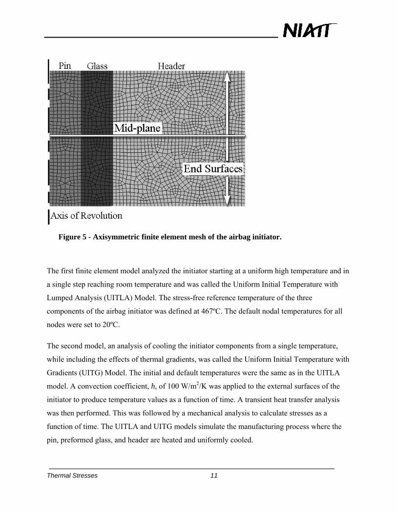
Figure 5 - Axisymmetric finite element mesh of the airbag initiator.
The first finite element model analyzed the initiator starting at a uniform high temperature and in
a single step reaching room temperature and was called the Uniform Initial Temperature with
Lumped Analysis (UITLA) Model. The stress-free reference temperature of the three
components of the airbag initiator was defined at 467ºC. The default nodal temperatures for all
nodes were set to 20ºC.
The second model, an analysis of cooling the initiator components from a single temperature,
while including the effects of thermal gradients, was called the Uniform Initial Temperature with
Gradients (UITG) Model. The initial and default temperatures were the same as in the UITLA
model. A convection coefficient, h, of 100 W/m2/K was applied to the external surfaces of the
initiator to produce temperature values as a function of time. A transient heat transfer analysis
was then performed. This was followed by a mechanical analysis to calculate stresses as a
function of time. The UITLA and UITG models simulate the manufacturing process where the
pin, preformed glass, and header are heated and uniformly cooled.
Thermal Stresses 12
The manufacturing process of pouring molten glass into the initiator was analyzed with the
Molten Glass with Lumped Analysis (MGLA) model and the Molten Glass with Gradients
(MGG) model. The MGLA model used the simplification that the glass begins at the glass
transition temperature (467ºC), the header and pin begin at room temperature (20ºC), and in a
single step the entire initiator cooled to room temperature. The nodal and stress-free reference
temperatures of the 8061 glass were set at 467ºC and the nodal and stress-free reference
temperatures of both the alloy 52 pin and stainless steel header were set at 20ºC.
For the MGG model, an analysis similar to the MGLA, but including thermal gradients due to
the pouring of molten glass into the initiator was performed. A convection coefficient, h, of 100
W/m2/K, was applied to the external surfaces of the initiator and then a transient heat transfer
analysis was performed where the entire assembly cooled to room temperature during a time
period of 10 seconds. Finally, a mechanical analysis was used to calculate the stresses as a
function of time.
RESULTS AND DISCUSSION
Closed Form Solutions
1. Parametric Study
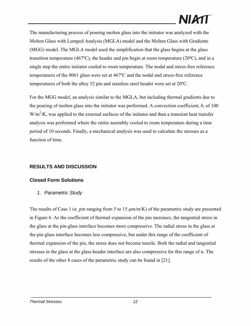
The results of Case 1 (α_pin ranging from 5 to 15 μm/m/K) of the parametric study are presented
in Figure 6. As the coefficient of thermal expansion of the pin increases, the tangential stress in
the glass at the pin-glass interface becomes more compressive. The radial stress in the glass at
the pin-glass interface becomes less compressive, but under this range of the coefficient of
thermal expansion of the pin, the stress does not become tensile. Both the radial and tangential
stresses in the glass at the glass-header interface are also compressive for this range of α. The
results of the other 8 cases of the parametric study can be found in [21].
Thermal Stresses 13
Figure 6 - Critical stresses from Case 1 of parametric study.
From the parametric study, the overall trends that increase the magnitude of compressive stresses
in the glass can be identified. Ideally the initiator would be stress-free at room temperature, but if
exact matching of coefficients of thermal expansion between the materials is not possible, it
would be better to have a compressive stress within the glass than a tensile stress, since cracks
are generally initiated when a tensile stress is present. Table 3 summarizes the trends in the
parametric study that result in an increase of the compressive stress within the glass.
Thermal Stresses 14
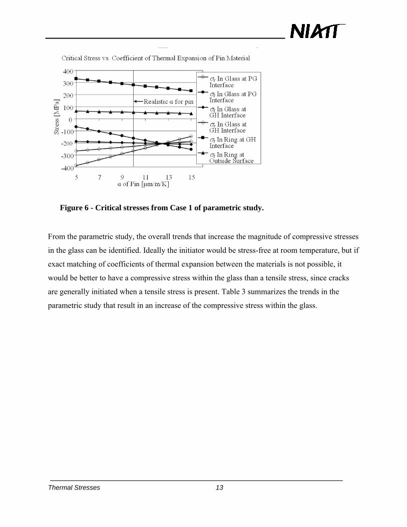
Table 3 - Summary of results of parametric study
Case Trend
1 There exists a value of coefficient of thermal expansion of pin that results in all critical stresses in glass having equivalent magnitudes.
2 A decrease in coefficient of thermal expansion of glass results in larger compressive stresses in glass.
3 An increasing coefficient of thermal expansion of header results in larger compressive stresses in glass.
4 An increasing modulus of elasticity of pin results in larger compressive radial and smaller compressive tangential stresses in glass.
5 A higher modulus of elasticity of glass results in larger compressive stresses in glass.
6 A higher modulus of elasticity of header results in larger compressive stresses in glass.
7 A larger diameter of pin results in larger compressive stresses for three critical stresses in glass.
8 A smaller outer diameter of glass results in larger compressive stresses in glass.
9 A larger diameter of header results in larger compressive stresses in glass.
2. Closed Form Initiator Manufacturing Models
The results of the closed-form analysis of the uniform cooling of the airbag initiator are shown in
Figure 7. It shows the radial and tangential stress profiles developed in the initiator as a function
of radial position. The closed-form model shows that the entire component will be under radial
compressive stress (left side of stress profile). The compression at the interfaces will help
maintain a seal between the glass and the metal components in case there is not perfect adhesion.
The entire GTMS is also under tangential compression. This will help to prevent radial cracking
of the component. Since the glass is stronger in compression than in tension, the likelihood of
failure due to uniform cooling of the entire initiator is low.
Thermal Stresses 15
Figure 7 - Closed form solution tangential and radial stress vs. radial position for uniform temperature change from 467ºC to 20ºC.
Thermal Stresses 16
Figure 8 - Closed form solution tangential and radial stress vs. radial position for pouring molten glass into initiator and cooling from 467ºC to 20ºC.
Figure 8 shows the results of the closed form analysis of pouring the molten glass into the space
between the header and pin. This analysis shows that there are tensile stresses developed in the
pin and glass. The entire initiator, with the exception of the outer surface, is under a radial tensile
stress and could potentially cause separation of the glass from the metal at the interfaces. These
tensile interfacial pressures (radial stresses) have resulted in a tangential tensile stress in the
glass. The tangential stress at the inner surface of the glass is of greater magnitude than that of
the outer surface due to the magnitudes of the interfacial pressures. The stress at the inner
surface, 345 MPa, is 60% of the characteristic strength of the glass, 554 MPa [21].
The closed form analysis clearly shows the potential for tensile stresses in the glass to be
developed. A FEA model was used to incorporate a two-dimensional geometry into, and further
investigate this problem.
Thermal Stresses 17
Finite Element Analysis
In the UITLA model, it was found that the entire pin and GTMS were under compression. The
radial stress is essentially compressive throughout the entire initiator, as the maximum tensile
stress is four orders of magnitude smaller than the maximum compressive stress. The tangential
stress is compressive throughout the entire pin and glass, but has a maximum tensile stress of
447 MPa in the header along the entire glass-header interface, shown as location 1 in Figure 9. It
should be noted that at the top and bottom end surfaces of the initiator, on the glass-header
interface, locations 3 and 4 of Figure 9, the radial compressive stress is of a much higher
magnitude than in the center of the initiator. This result is due to the convective cooling of the
end surfaces of the initiator.
Figure 9 - Finite element analysis critical stress locations
Of the four models in this research, the UITLA model is most similar to, and agrees with, what
was presented by Nattermann et al. [23], whose analysis included a pin that projected above and
below the glass, and a header that projected below the glass. The profile of the radial stress
contours and the magnitude of the radial stresses, in the area surrounding the upper glass-header
interface agree between this work and the work of Nattermann et al. [23]. The stress profile from
this FEA also shows agreement with the mechanics approach discussed earlier, as can be seen in
Thermal Stresses 18
Figure 10. The tangential stresses shown in Figure 10, describing the FEA, were extracted from
the horizontal mid-plane of the ALGOR model. The difference in the results for the FEA vs. CFS
is due to the three-dimensional effects included in the FEA, as axial strains increase the stress in
the radial and tangential directions proportionally to the axial strain. Since the header has a
higher coefficient of thermal expansion than the pin, the glass-header interface is placed under
more axial strain than the pin-glass interface. This results in more radial and tangential
compressive stress near the glass-header interface than elsewhere.
Figure 10 - Tangential stress vs. radial position for UITLA model and closed-form solution.
The UITG model found that radial and tangential tensile stresses occur in the glass. Again
referring to Figure 9, the peak radial stress in the glass was 5.0 MPa, on the end surface at the
interface of the glass and the pin, location 3. The peak tangential stress in the glass was 5.9 MPa,
at the middle of the end surface of the glass, location 2. The stresses were greater at the end
surfaces than at the mid-plane. It is important to note that the maximum tangential stress is
greater than the maximum radial stress thus the likelihood of radial cracks, as shown previously
in Figure 1, is greater.
Thermal Stresses 19
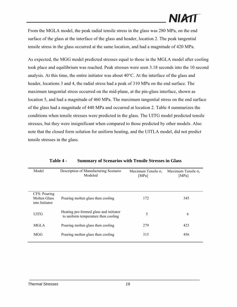
From the MGLA model, the peak radial tensile stress in the glass was 280 MPa, on the end
surface of the glass at the interface of the glass and header, location 2. The peak tangential
tensile stress in the glass occurred at the same location, and had a magnitude of 420 MPa.
As expected, the MGG model predicted stresses equal to those in the MGLA model after cooling
took place and equilibrium was reached. Peak stresses were seen 3.18 seconds into the 10 second
analysis. At this time, the entire initiator was about 40°C. At the interface of the glass and
header, locations 3 and 4, the radial stress had a peak of 310 MPa on the end surface. The
maximum tangential stress occurred on the mid-plane, at the pin-glass interface, shown as
location 5, and had a magnitude of 460 MPa. The maximum tangential stress on the end surface
of the glass had a magnitude of 440 MPa and occurred at location 2. Table 4 summarizes the
conditions when tensile stresses were predicted in the glass. The UITG model predicted tensile
stresses, but they were insignificant when compared to those predicted by other models. Also
note that the closed form solution for uniform heating, and the UITLA model, did not predict
tensile stresses in the glass.
Table 4 - Summary of Scenarios with Tensile Stresses in Glass
Model
Description of Manufacturing Scenario Modeled
Maximum Tensile r [MPa]
Maximum Tensile t [MPa]
CFS: Pouring Molten Glass into Initiator
Pouring molten glass then cooling 172 345
UITG Heating pre-formed glass and initiator to uniform temperature then cooling
5 6
MGLA Pouring molten glass then cooling 279 423
MGG Pouring molten glass then cooling 315 456
Thermal Stresses 20
CONCLUSIONS
This research predicts that radial cracks form in the initiator when molten glass is poured into the
initiator or if the surface of the initiator is cooled more quickly than the center. If the coefficient
of thermal expansion can be matched between the pin, glass, and header, the probability of
failure of an initiator will be greatly reduced, as the likelihood of failure from non-uniform
cooling is much less than that of failure due to pouring molten glass into the initiator. To reduce
the probability of failure, a manufacturer should use processes that involve cooling the entire
initiator from a given temperature in manufacture, and it should be cooled slowly to ensure that
the temperature difference between the surface and interior is minimized. Using pre-formed glass
components appears to be satisfactory. However, because tensile stresses can be caused by a
number of factors, the exact manufacturing process needs to be carefully analyzed. It is
imperative that molten glass not be poured into the rest of the initiator at room temperature, as
the likelihood of failure of the initiator due to tensile stresses is high.
REFERENCES
[1] “Traffic Safety Facts 2004.” National Center of Statistics & Analysis. DOT HS 809 919. 2004.
[2] USCAR24 Inflator Technical Requirements and Validation, Society of Automotive Engineers, June 2004.
[3] Miyake, A., Nishiyama, N., Oka, Y., and T. Ogawa, 2001, Moisture Effect on the Rate of Corrosion of Bridge Wire and its Lifetime Prediction, Proceedings of the Twenty-Eighth International Pyrotechnics Seminar, Adelaide, South Australia, November 4th-9th, pp. 545 – 551.
[4] Tibbitts, E. and R. F. Salerno, 1980, Nickel-Iron Alloy Corrosion in a Sealed Pyrotechnic System, Proceedings of the Seventh International Pyrotechnics Seminar, International Pyrotechnics Seminars U.S.A., Inc., pp. 629 – 649.
[5] Ballard, C. P., R.J. Eagan, and E. A. Kjeldgaard, 1980, Glass Ceramics for Explosive Device Headers, Proceedings of the Seventh International Pyrotechnics Seminar, International Pyrotechnics Seminars U.S.A., Inc., pp. 32 – 50.
[6] Massis, T.M., Healey, J.T., Huskisson, D.H., and W.G. Perkins, 1982, “Corrosion Problems in Titanium/Potassium Perchlorate Loaded Devices When Subjected to Humidity Environments”, Journal of Hazardous Materials, 5, pp. 335 – 351.
[7] Moses, S. A., 1971, Long-Life Aerospace Explosive Components, Proceedings of the 7th Symposium on Explosives and Pyrotechnics, Philadelphia, Pennsylvania, September 8th-9th.
Thermal Stresses 21
[8] Klein, M. K. and K. K. Rink, 2003, Pyrotechnic Initiator research at the University of Idaho, 19th International Colloquium on the Dynamics of Explosions and Reactive Systems, Hakone, Japan, July 27th – August 1st.
[9] Neff, G. R. and J. K. Neff, 2005, Testing of Non-hermetic Initiators for Improved Airbag System – Issues and Needs, SAE 2005-01-0743, Proceedings of the 2005 SAE World Congress, Detroit, Michigan, April 11th-14th.
[10] Forman, D., 1999, Automotive Initiator Technology, AIAA paper 99-2422, 35th AIAA/ASME/SAE/ASEE Joint Propulsion Conference and Exhibit, Los Angeles, California, June 20th-24th.
[11] Hull, A.W. and Burger E. E., 1934, Glass-to-Metal Seals,” Physics, 5, pp. 384-405.
[12] Borom, M. P., and Giddings, R. A., 1976, “Considerations in Designing Glass/Metal Compression Seals to Withstand Thermal Excursions,” Ceramic Bulletin, 55-12, pp. 1046-1048, 1051.
[13] Kokini, K., 1982, “Thermal Stress Analysis of Annular Glass-to-metal Seals Under Thermal Shock,” Ph.D. Dissertation, Department of Mechanical Engineering, Syracuse University, Syracuse, New York.
[14] Lee, Z.-Y., Chen, C. K., and Hung, C.-I., 2001, “Transient Thermal Stress Analysis of Multilayered Hollow Cylinder,” Acta Mechanica, 151, pp. 75-88.
[15] Jane, K. C., and Lee, Z. Y., 1999, “Thermoelasticity of Multilayered Cylinders,” J. Thermal Stresses, 22, pp. 57-74.
[16] “Technical Data Sheet HPM NI 52,” 2001, Hamilton Precision Metals, Inc., Data Sheet, 2001.
[17] Schott Glass, 1998, “Electronic Packaging – Glass-to-Metal Seals.” Brochure, Landshut.
[18] Metals Handbook, 1990, 10th ed., vol. 1, ASM International Handbook Committee, ASM International, Materials Park, OH.
[19] Boresi, A. P. and Schmidt, R. J., 2003, Advanced Mechanics of Materials. John Wiley & Sons, Inc., New York, 6th Ed., pp. 389-418.
[20] Shigley, J. E. and Mischke, 2001, C. R., Mechanical Engineering Design. McGraw-Hill, New York, 6th Ed., pp. 94-154.
[21] Thompson, L. M., 2005, “Thermal Stresses in Airbag Initiators,” Master’s Thesis, Department of Mechanical Engineering, University of Idaho, Moscow, Idaho.
[22] Rink, K. K., Blackketter, D. M., and Thompson, L. M., 2005, “Thermal Stresses and Potential Failure Mechanisms in Airbag Initiators.” The Sixth International Congress on Thermal Stresses, TS2005, Vol. 1, Vienna, pp. 301-304.
[23] Nattermann, K., Krümmel, H., and Frank, L., 2002, “Strength Optimization of Airbag Initiators.” Mathematical Simulation in Glass Technology, Krause, D. and Loch, H., Eds., Springer, Berlin, pp. 413-438.