Embed Size (px)
Citation preview

THERMAL RESISTANCE OF INTERLOCKING BLOCK WALL WITH INFILL
MUHAMMAD ASYRAF BIN ZULKIFLI
Project Report submitted as partial fulfillment of the
requirements for the award of the degree of
B.Eng. (Hons.) Civil Engineering
Faculty of Civil Engineering and Earth Resources
UNIVERSITI MALAYSIA PAHANG
JULY 2015

vi
ABSTRACT
In the era of global warming and decreasing resources material today, the
awareness of the important of the energy efficient building have increased. A lot of
studies about thermal insulation material and thermal conductivity have been carried out
to find the solution due to global warming. Interlocking block or Compress Stabilized
Earth Block (CSEB) have been widely use today due to its effectiveness especially in
reducing the cost and time. Sawdust and polystyrene can act as thermal insulation and
hence the usage of sawdust and polystyrene as thermal insulation in building can
decrease the waste material from the construction. This study have been carried out to
determine the thermal conductivity of interlocking block wall with three different type
of infill which are sawdust, polystyrene and polystyrene mix with cement. The thermal
resistance test have been conduct based on MS 1532:2002 using guarded hot box
method. The higher the R-value or thermal resistance reading means the better the
thermal resistance of the material. The result for the sawdust as infill is 1.71 K/kW,
polystyrene infill is 2.12 K/kW, and polystyrene mix with cement is 1.54 K/kW.
The results show that wall with polystyrene as infill have better thermal insulation than
sawdust as infill and polystyrene mix with cement as infill.
vii
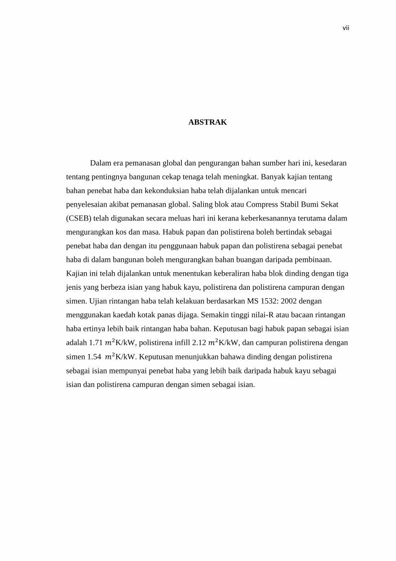
ABSTRAK
Dalam era pemanasan global dan pengurangan bahan sumber hari ini, kesedaran
tentang pentingnya bangunan cekap tenaga telah meningkat. Banyak kajian tentang
bahan penebat haba dan kekonduksian haba telah dijalankan untuk mencari
penyelesaian akibat pemanasan global. Saling blok atau Compress Stabil Bumi Sekat
(CSEB) telah digunakan secara meluas hari ini kerana keberkesanannya terutama dalam
mengurangkan kos dan masa. Habuk papan dan polistirena boleh bertindak sebagai
penebat haba dan dengan itu penggunaan habuk papan dan polistirena sebagai penebat
haba di dalam bangunan boleh mengurangkan bahan buangan daripada pembinaan.
Kajian ini telah dijalankan untuk menentukan keberaliran haba blok dinding dengan tiga
jenis yang berbeza isian yang habuk kayu, polistirena dan polistirena campuran dengan
simen. Ujian rintangan haba telah kelakuan berdasarkan MS 1532: 2002 dengan
menggunakan kaedah kotak panas dijaga. Semakin tinggi nilai-R atau bacaan rintangan
haba ertinya lebih baik rintangan haba bahan. Keputusan bagi habuk papan sebagai isian
adalah 1.71 K/kW, polistirena infill 2.12 K/kW, dan campuran polistirena dengan
simen 1.54 K/kW. Keputusan menunjukkan bahawa dinding dengan polistirena
sebagai isian mempunyai penebat haba yang lebih baik daripada habuk kayu sebagai
isian dan polistirena campuran dengan simen sebagai isian.

viii
TABLE OF CONTENTS
Page
SUPERVISOR’S DECLARATION ii
STUDENT’S DECLARATION iii
ACKNOWLEDGEMENT v
ABSTRACT vi
ABSTRAK vii
TABLE OF CONTENTS viii
LIST OF TABLE xi
LIST OF FIGURES xii
LIST OF ABBREVATIONS xiii
CHAPTER 1 INTRODUCTION
1.1 Introduction 1
1.2 Problem Statement 2
1.3 Objectives 2
1.4 Scope of study 3
1.5 Research Significance 3

ix
CHAPTER 2 LITERATURE REVIEW
2.1 Introduction 4
2.2 Interlocking Block 4
2.3 Thermal Insulation 7
2.3.1 Styrofoam 8
2.3.2 Sawdust 9
CHAPTER 3 MATERIALS AND METHODOLOGY
3.1 Introduction 10
3.2 Sample Preparation 10
3.2.1 Cement 11
3.2.2 Laterite Soil 11
3.2.3 Fine Aggregate 11
3.2.4 Sawdust 11
3.2.5 Styrofoam 12
3.2.6 Water 12
3.3 Interlocking Block Wall 13
3.4 Laboratory Testing 16
x
3.4.1 Compression Strength Test 17
3.4.2 Guarded Hot Box 18
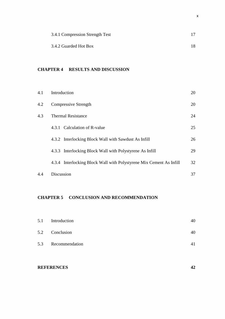
CHAPTER 4 RESULTS AND DISCUSSION
4.1 Introduction 20
4.2 Compressive Strength 20
4.3 Thermal Resistance 24
4.3.1 Calculation of R-value 25
4.3.2 Interlocking Block Wall with Sawdust As Infill 26
4.3.3 Interlocking Block Wall with Polystyrene As Infill 29
4.3.4 Interlocking Block Wall with Polystyrene Mix Cement As Infill 32
4.4 Discussion 37
CHAPTER 5 CONCLUSION AND RECOMMENDATION
5.1 Introduction 40
5.2 Conclusion 40
5.3 Recommendation 41
REFERENCES 42
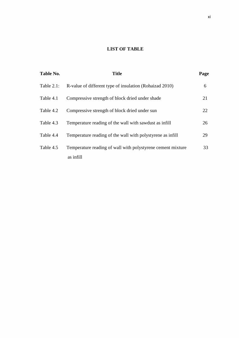
xi
LIST OF TABLE
Table No. Title Page
Table 2.1: R-value of different type of insulation (Rohaizad 2010) 6
Table 4.1 Compressive strength of block dried under shade 21
Table 4.2 Compressive strength of block dried under sun 22
Table 4.3 Temperature reading of the wall with sawdust as infill 26
Table 4.4 Temperature reading of the wall with polystyrene as infill 29
Table 4.5 Temperature reading of wall with polystyrene cement mixture 33
as infill
xii
LIST OF FIGURES
Figure No. Title Page
Figure 3.1 Styrofoam Board 12
Figure 3.2 Hydraulic Press Machine 14
Figure 3.3 Reinforcement at interlocking block walls 15
Figure 3.4 Polystyrene as infill of the wall 15
Figure 3.5 Sawdust as infill of the wall 15
Figure 3.6 Finish wall with apparatus set-up 16
Figure 3.7 Compressive Strength Machine 17
Figure 3.8 Guarded hot box 18
Figure 3.9 Thermocouple Type K 19
Figure 3.10 Wall set-up for testing 19
Figure 4.1 Average compressive strength between two curing 23
method
Figure 4.2 Temperature of the wall with sawdust infill 28
Figure 4.3 Temperature reading of the wall with polystyrene infill 31
Figure 4.4 Temperature reading of the wall with polystyrene cement 35
mix infill
Figure 4.5 Temperature different of the walls 37
Figure 4.6 Temperature different of the walls from previous study 38
Figure 4.7 R-value for different type of infill from previous study 39

xiii
LIST OF ABBREVATIONS
CSEB Compressed Stabilized Earth Block
MS Malaysian Standard
OPC Ordinary Portland Cement
BS British Standard

CHAPTER 1
INTRODUCTION
1.1 INTRODUCTION
Urbanization and socio-economic are among the factors that prompt to the
invention of interlocking block or dry masonry stack. In Africa, interlocking block was
invented to solve the housing problem due the rise in costs of land and building
materials while in Thailand, interlocking block was develop to reduce the usage of
timber.
Interlocking block reduces the usage of industrial products like cement and
relies on local resources. It is considered to an effective and environmental friendly
technology because it consumes less production energy, reduces deforestation, decrease
the utilization of non-renewable resources and produce less waste from construction
process.

2
1.2 PROBLEM STATEMENT
Wall is one of the main components in construction of the building. Wall will
transfer the load from above such as upper floor and roof truss and transfer it to the
foundation below the ground. Wall also acts as a rain control layer, an air control layer,
a vapor control layer and a thermal control layer. In some countries especially cold
climate countries in North America and Europe, wall with insulation materials was built
to give some heat during the winter. Heat will always flow from a warm area to a cold
one. In winter, the colder it is outside, the faster heat from the house will escape into the
surrounding air. Thermal resistance is one of the main aspects in construction of houses.
Builders are finding methods to insulate the wall rather than using the conventional
way.
Due to global warming, people today prefer to use air conditioner in their house.
The usage of air conditioner is one the main factor contributes to the global warming.
Although there are energy efficient air conditioners, not all people can‟t afford to buy it.
Hence, this study will investigate the role of infill in retaining heat especially in the
wall.
1.3 OBJECTIVES
The objectives of this proposed topic are as follows:
i. To determine the compressive strength of the blocks
ii. To determine the thermal resistances of interlocking block walls
with three different types of infill.
iii. To compare which infill have better thermal resistance.

3
1.4 SCOPE OF STUDY
The scope of this proposed topic is focusing on:
1. To produce interlocking Compress Stabilized Earth Blocks (CSEB).
2. To test compressive strength of the blocks.
3. To design and build block wall with 1x1.05 m dimension using interlocking
blocks.
4. To test the thermal resistance of the wall with three different conditions:
a) Wall with sawdust as infill
b) Wall with polystyrene as infill
c) Wall with polystyrene mix with cement as infill
1.5 RESEARCH SIGNIFICANCE
With this research, the usage of industrial waste material such as sawdust and
the introduction of Styrofoam as insulation material in interlocking block could be an
alternative to conventional masonry wall especially in Malaysia.
This research can promote to the application of energy efficient building and
give better understanding to the usage of Styrofoam and sawdust as insulation material
in interlocking block construction.

CHAPTER 2
LITERATURE REVIEW
2.1 INTRODUCTION
An energy efficient building envelope contains both a thermal barrier and an air
barrier. The key to an effective thermal barrier is proper installation of quality insulation
products. A house should have a continuous layer of insulation around the entire
building envelope. Studies show that improper installation can cut performance by 20 %
or more (Fehr 2009). There is several type of insulator available nowadays as the whole
world is moving towards green environment and the increasing of green energy building
demand.
2.2 INTERLOCKING BLOCK
Urbanization, housing shortage, and deforestation is among the problem that
lead to the search of appropriate, easy, fast, and cost effective of new wall construction.
In Thailand, 70 % forest covered in 1936 has decreased to 55 % only in 1961 and now
around 30 % is left. Hence, the government developed a research to use alternative
materials to be used in construction especially in rural area. Among the solution is

5
mortarless technology using dry stack interlocking blocks. Thailand Institute of
Scientific and Technological Research (TISTR) have proved that house built with
interlocking block is cheaper than house built by timber. (Weinhuber, 1995)
Interlocking block usage increase around the world and have been accepted as
one of the new technologies that is more effective than the conventional way.
Interlocking blocks have a lot of advantage such as increasing the construction
productivity, reduction in construction duration and labor use and reduced construction
cost. The cost of construction of the wall using interlocking block is estimated 40 %
lower than using more conventional materials (Kitingu, 2009)
There are many systems or interlocking block types that have been develop.
Among them is Mechano System which has been developing in Peru. Mechano System
not involved interlocking geometry and it gain it‟s stability through grouting process.
Sparfil System develops in Canada, which develop by using light weight concrete
(Jasim, 2014). There other systems are Allan Block System, Auram System, Hyner
Blocks, Hydraform Systems, Putra Blocks, and Solbric System.
Interlocking blocks followed a few concept or principles where the blocks are
shaped with projecting parts. It fit exactly into depression in the blocks placed above,
such that they are automatically aligned horizontally and vertically. Thus, bricklaying is
possible without special masonry skills. There were vertical hole in the block to reduce
the weight of the block and to insert steel rods for reinforcement, and/or to pour liquid
mortar which runs through the full height of the wall, making it more stable. (Rohaizad,
2010)
6
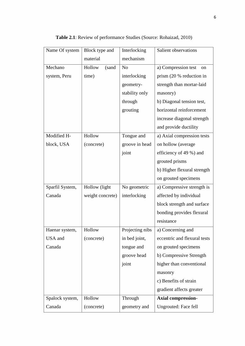
Table 2.1: Review of performance Studies (Source: Rohaizad, 2010)
Name Of system Block type and
material
Interlocking
mechanism
Salient observations
Mechano
system, Peru
Hollow (sand
time)
No
interlocking
geometry-
stability only
through
grouting
a) Compression test on
prism (20 % reduction in
strength than mortar-laid
masonry)
b) Diagonal tension test,
horizontal reinforcement
increase diagonal strength
and provide ductility
Modified H-
block, USA
Hollow
(concrete)
Tongue and
groove in head
joint
a) Axial compression tests
on hollow (average
efficiency of 49 %) and
grouted prisms
b) Higher flexural strength
on grouted specimens
Sparfil System,
Canada
Hollow (light
weight concrete)
No geometric
interlocking
a) Compressive strength is
affected by individual
block strength and surface
bonding provides flexural
resistance
Haenar system,
USA and
Canada
Hollow
(concrete)
Projecting nibs
in bed joint,
tongue and
groove head
joint
a) Concerning and
eccentric and flexural tests
on grouted specimens
b) Compressive Strength
higher than conventional
masonry
c) Benefits of strain
gradient affects greater
Spalock system,
Canada
Hollow
(concrete)
Through
geometry and
Axial compression-
Ungrouted: Face fell

7
stacking
pattern
cracking close to ultimate
load.
Grouted specimens: Face
shell cracking well before
ultimate load due to lateral
tensile strains in grout
a) Lateral load tests on
hollow block wall
specimens
b) Finite-element analysis
to predict stress
distribution in bending and
moment capacities of dry
stack assembly.
Many literatures on interlocking block are produced. However, the results on
behavioral characteristics of the block are available for a few only (Ramamurthy, 2005).
The development of interlocking blocks reveals that:
a) Many blocks have complex shapes, which appear to have been deliberate, and such
intricacies in block geometry (tongue and groove or undercut and dovetail arrangement)
necessitate mechanized production methods.
b) The presence of continuity of horizontal and vertical joints from inner to outer face.
2.3 THERMAL INSULATION
Thermal insulation can be refers either to materials used to reduce the rate of
heat transfer, or the methods and processes used to reduce heat transfer.

8
Heat is transferred by from one material to another by conduction, convection or
radiation. Insulators are used to minimize that transfer of heat energy. The R-value is an
indication of how well a material insulates.
Thermal insulators are those materials or combination of several materials which
retard the flow of heat energy. Installation of thermal insulation can significantly reduce
the thermal energy lost from thermal heat storage.
Insulation materials can be made from many different type or forms such as
loose-fill form, blanket bat or roll form, in place foamed, rigid form or reflective form.
(Gertrude 2011).
2.3.1 Styrofoam
Styrofoam, or polystyrene foam, is petroleum-based plastic foam with
exceptional insulated properties. Styrofoam is 95 % air, allowing it to trap warm air and
prevent heat loss when used as insulation in a building or a disposable coffee cup. The
trapped air inside the Styrofoam prevents heat from effectively passing out making
heating system more efficient.
Ray McIntire, scientist from Dow Chemical Company, accidentally
invented foamed polystyrene or Styrofoam. McIntire tried to make a new rubber-like
polymer by combining styrene with isobutylene, a volatile liquid, under pressure. The
result was foam polystyrene with bubble, 30 times lighter than regular polystyrene. The
Dow Chemical Company introduced Styrofoam products to the United State in 1954.
(Friend, 2005)

9
2.3.2 Sawdust
Sawdust is a by-product of cutting, grinding, drilling, sanding, or
otherwise pulverizing wood with a saw or other tool. It is composed of fine particles of
wood (Junior, 2014).
Sawdust or cellulose could offer the development business a powerful,
ecologically cordial option to tradition protection as it has moderately high warm
qualities (Cordis, 2012).

CHAPTER 3
MATERIALS AND METHODOLOGY
3.1 INTRODUCTION
This chapter will describe the procedure and execution of works in details. It
will discuss from the preparation of sample to the testing procedure that involved in this
study.
3.2 SAMPLE PREPARATION
The material that will be used to produce the interlocking block need to be
prepared first. The materials used are cement, fine aggregate, laterite soil.
11
3.2.1 Cement
There are mixed bags of concrete accessible in the business. For this
study, the Ordinary Portland Cement (OPC) is chosen. The choice focused around the
regular practice as this kind of bond is generally utilized as a part of development
procedure.
There are a lot of cements available but for this studies OPC is used
because it is the most common and widely used in the market.
3.2.2 Laterite Soil
Laterite soil is obtained from nearby location at University Malaysia
Pahang and used as one of the component of the interlocking block where the laterite
soil will be mix with the cement and sand in the proportion of 1.4:2:6.
3.2.3 Fine Aggregate
In this study, fine sand or river sand will be used as fine aggregate. River
sand is the most commonly and easiest fine aggregate that can be get from the supplier.
3.2.4 Sawdust
Sawdust can be getting from the sawmill nearer, Sawmill Gambang Sdn
Bhd, and will be used as one of the infill in the interlocking block wall.

12
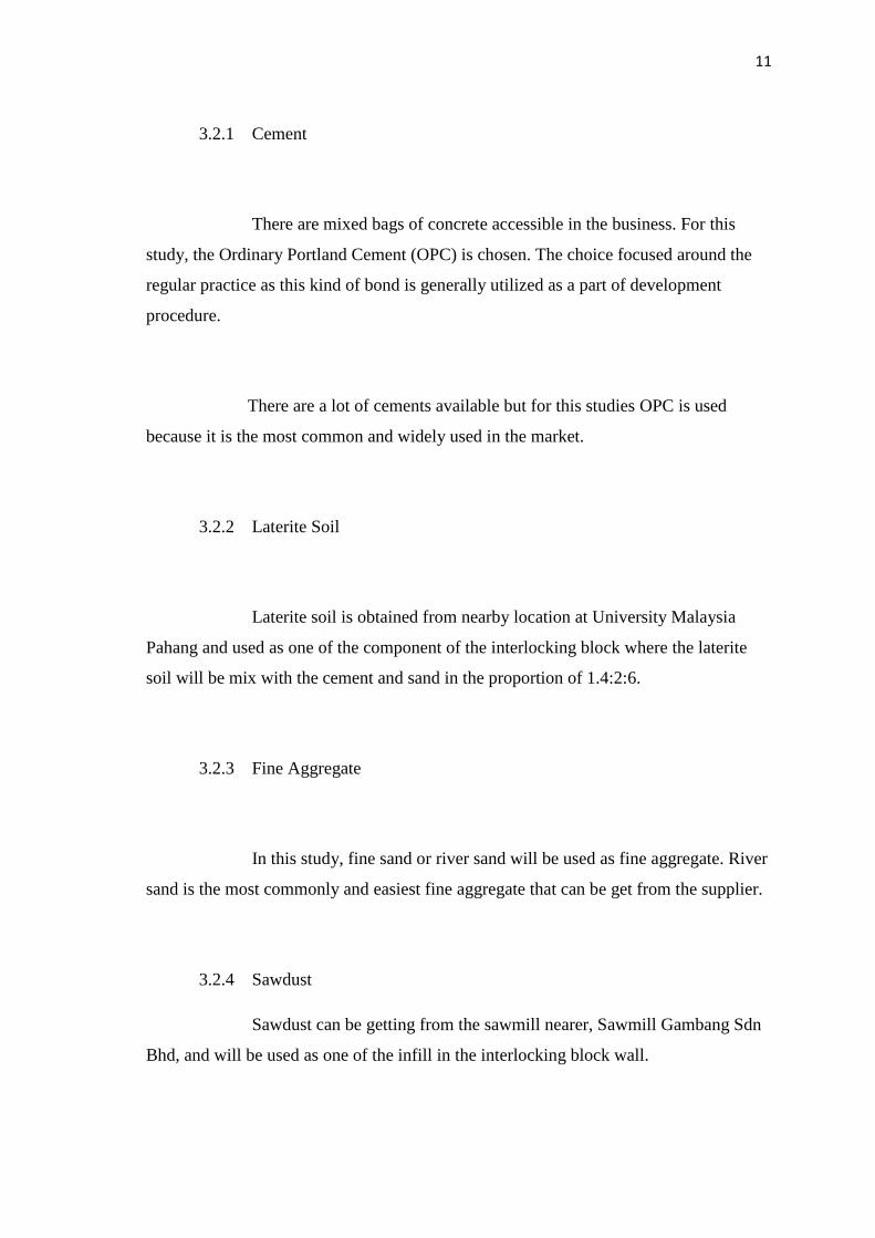
3.2.5 Styrofoam
Styrofoam can be getting from any bookstall nearer and will be used as
one of the infill in the interlocking block wall.
3.2.6 Water
Water is required in mixing procedure. The amount water content will be
used for mixing process is 10 % from the weight of the sand.
Figure 3.1: Styrofoam board

13
3.3 INTERLOCKING BLOCK WALL
For this study, the interlocking block produced by using ratio 1.4:2:6 of cement,
laterite soil and sand mixture. The interlocking block dimension is 100x125x300 mm
for regular size, 100x150x300 mm for corner block and half block size is 100x125x150
mm. First, the cement, laterite soil and sand need to be weight according to the ratio
which is 6 kg for normal block and 6.7 kg for corner block. The batch will be mix by
mixer machine. Then water will be added to the mixture. The weight of water used is
10% from the weight of sand. Then the batch will be poured into the mould of hydraulic
press machine to produce the block.
Figure 3.2: Hydraulic Press Machine

14
The finish blocks will be used to produce three set of wall with 1.0x1.05m
dimension. 35 blocks is used for each set of wall with overall 105 total blocks is used
for the three set of walls. For each set of the wall, a total of 10 layers of interlocking
block is need.
Reinforcement or rebar is place at every corner of the wall to make sure the wall
is steady and not moving. After half of the wall is build (5 layers of interlocking
blocks), the wall is grouted with three type of infill as have been mention in the
objective to ensure all cavity in the hollow section is filled. After the wall is finished,
the top and the wall surface will be grouted with mortar to create a solid wall. The wall
then will be covered with the plywood-Styrofoam panel.

15
Figure 3.4: Reinforcement at interlocking block walls
Figure 3.5: Polystyrene as infill of the wall
Figure 3.6: Sawdust as infill of the wall