Embed Size (px)
Citation preview

A D
TECHNICAL REPORT ARLCB-TR-8200.4
THERMAL RELAXATION IN AUTOFRETTAGED CYIUNDERS
Joseph F. Throop- John H. Underwood
Gregory S. Leger
March 1982
US ARMY ARMAMENT RESEARCH AND DEVELOPMENT COMMANDLARGE CALIBER WEAPON SYSTEMS LABORATORY
BEN&'T WEAPONS LABORATORY
WATERVLIET, N. Y. 12189
AMCMS No. 6121.05.HB40.0.
PRON No. AW-1-RBWL1-AW1A
Q.. APPROVED FOR PUBLIC RELEASE; DISTRIBUTION UNLIMITED
-4Z
82 04 07 057

DISCLAIMJ~
The findings in this report are not to be construed as an official
Depa:tment of the Akrmy position unless so designated by other author-
ized documents.
The use of trade name(s) and/or 'manufacture(q) does not consti-
tute an official indorsement or approval.
DISPOSITION
Destroy this report when it is no longer needed. Do not return it
to the originator.
iI
.r ... ..
~~~~~~~.......... , ~ ,.k z~t.~i.M

SECURITY CLASSIFICATION OF THIS PAGE (When Date Entered)
REPORT DOCUMENTATION PAGE READ tNSTRUCTIONSBEFORE COMPLETING FORM
1. REPORT NUMBEIR 2. GOVT ACCESSION NO. 3. RECIPIENT'S CATALOG NUMBER
ARLCB-TR-82004 k/: i'4. TIT.E (andSubtleto) S. TYPE OF REPORT & PERIOD COVERED
THERMAL RELAXATION IN AUTOFRETTAGED CYLINDERS
6. PERFORMING ORG. REPORT NUMBER
7. AUTmOR(e)1 S. CONTRACT OR GRANT NUMBER(s)
Joseph F. Throop, John H. Underwood, andGregory S. Legers. PERFORMING ORGANIZATION NAME AND ADDRESS 10. PROGRAM ELEMENT. PROJECT, TASK
AREA & WORK UNIT NUMBURS
US Army Armament Research & Development Command AMCMS No. 6121.05.HB40.0Benet Weapons Laboratory, DRDAR-LCB-TL PRON No. AW-l-RBWLI-AWIAWatervliet, NY 1218911- CONTROLLING OFFICE NAME AND ADDRFSS 12. REPORT DATE
US Army Armament Research & Development Command March 1982Large Caliber Weapon Systems Laboratory Is. NUMBER OF PAGES
jDove r. NJ 07S01 38S 1MONITORING AGENCY NAME & ADDRESS(II diferent from Controlling Office) IS. SECURITY CLASS. (of thie report)
UNCLASSIFIED
15I, DECLASSIFICATION/DOWNGRAD!NGSCHEDULE
1S. DISTRIBUTION STATEMENT (of thle Report)
Approved for public release; distribution unlimited.
17. DISTRIBUTION STATEMENT (of the abstract entered in Block 20, It different from Report)
II. SUPPLEMENTARY NOTES
Presented at 28th Sagamore Army Materials Research Conference,Lake Placid, NY, 13-17 July 1981.Published in proceedings of the conference.
19. KEY WORDS (Continue on revered side It ne*eeeary end identify by block number)
Autofrettaged Cylinders Thermal StressesOvers train RelaxationResidual Str'sses Bore ClosureThermal Gradient
2&. AIsr'ACr (mm I ýr-eva, ab, I nem..omy moid Idwaitf by block number)
' This report presents an experimental study on the loss of bore expansion andchange of residual stresses in autofrettaged cylinders, resulting frominternal heating combined with exLernal cooling. It provides informationuseful in the design of pressure vessels operating at high temperature. Two-foot long cylinders were heated internally to bore temperatures up to 950*Fand simultaneously cooled externally to produce a temperature difference of as
(CONT'D ON REVERSE)
DDre 14n t. Era'now or,,v* Is NO 6 1|.30ETFA 173! UNCLASSIFIED
SECURITY CLASSIFICATION OF THIS PAGE (When Data Entered)
* .

SECURITY CLASSIFICATION OF THIS PAGI(Wha, Data Enierod)
20. ABSTRAcTr (CONT'D)
•uch as 7250F from bore to outside surface. Reduction of the autofreLLagebore expansion and reduction of residual stresses resulted, because thethermal stresses added to the residual stresses and exceeded the loweredyield strength at elevated temperature, permitting relaxation to occur.
The data reveals that under certain temperatuTru conid Lloons a coo I'll- ra-1 1portion of the autofrettage induce L bore expansion and the associatedresidual stresses can be lost in a few minutes when exteLnal cooling occurs.The experimental results indicate that partial overstrain in autofretLage mayLe preferable to full overstrain in order to minimize the loss in residual
SECURITY CLASSIFICATION OF THIS PAGE(i47ý,, Dea taI,terod)

TABLE OF CONTENTS
Page
ACKNOWLEDGEMENT iii
LIST OF SYMBOLS AND TERMS iv
INTRODUCTION 1
OBJECT 2
SPECIMENS 3
PROCEDURE 4
RESULTS AND DISCUSSION 6
CONCLUSIONS 33
REFERENCES 34
TABLES
S. DIMENSIONS AND AUTOFRETTAGE BORE EXPANSIONS 3
S2a. STRAINS RELIEVED AND SEPARATION ANGLES 7
21). STRAINS RELIEVED AND SEPARATION ANGLES 8
LIST OF ILLUSTRATIONS
1. Heating and Cooling Arrangement. 4
2. Residual Stress versus Radius, OD/ID -2.14. 11
3. Residual Stress versus Radius, OD/ID 1.82. 12
4. Temperature Distribution, OD/ID - 2.14, for the I_Forced Air Cooling Condition.
5. Bore Closure versus Delta T, 100% Overstrain, 15OD/ID - 2.14.
6. Bore Closure versus Delta T, 75% Overstrain, 16OD/ID - 2.14.
iiI
A
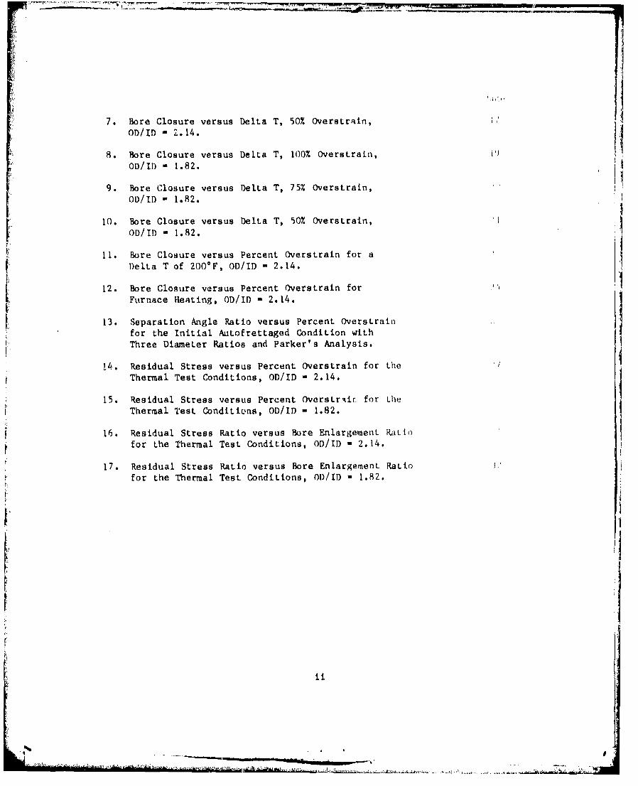
7. Bore Closure versus Delta T, 50% Overstrain, hOD/ID - 2.14.
8. Bore Closure versus Delta T, 100% Overstrain,OD/ID - 1.82.
9. Bore Closure versus Delta T, 75% Overstrain,OD/ID - 1.82. I
10. Bore Closure versus Delta T, 50% Overstrain,OD/ID - 1.82.
11. Bore Closure versus Percent Overstrain for aDelta T of 200*F, OD/ID - 2.14.
12. Bore Closure versus Percent Overstrain forFurnace Heating, OD/ID - 2.14.
13. Separation Angle Ratio versus Percent Overstrainfor the Initial Autofrettaged Condition with
Three Diameter Ratios and Parker's Analysis.
14. Residual Stress versus Percent Overstrain for the
Thermal Test Conditions, OD/ID - 2.14.15. Residual Stress versus Percent OverstrAir. for Lhe
Thermal Test Conditions, OD/ID - 1.82.
16. Residual Stress Ratio versus Bore Enlargement Ratiofor the Thermal Test Conditions, OD/ID - 2.14.
17. Residual Stress Ratio versus Bore Enlargement Ratiofor the Thermal Test Conditions, OD/ID - 1.82.
ii
• • •' .. . .. . . ' 'It
ACKNOWLEDGEMENT 1
This work was performed under funding from Project Number 612105.H840011
of the Army Materials and Mechanics Research Center, Watertown, MA. We are
pleased to acknowledge the help of R. R. Fujczak, R. T. Abbott, W. M. Yaiser,
H. R. Alford, and C. C. DeLaMater in performing the experiments described
here, of C. Prokrym for photography and of Ellen Fogarty for preparing the
manuscript.
I{
.I
tii

LIST OF SYMBOLS AND TERMS
a - radius to inside wall
b - radius to outside wall
r - radius to any point in the wall
p - radius of the elastic-plastic interface
OD - outside diameter of ring
ID - inside diameter of ring
y - angle of opening of the ring at the slit
M - moment needed to close slit opening of the ring
a0 - tangential stress
ay - yield strength
Ace - change in tangential strain
BC - bore closure; loss of bore expansion
BE - bore enlargement
E - modulus of elasticity - 30 x 106 psi
! •Yexper imental
Separation Angle Ra tio -------
38
Residual Stress Ratio - e
Oatheoretical
BEfinal
Bore Enlargement Ratio-- ---------CEinitial
Ii
iv
;
,I
-." 1•-
-- = ... " . . ., . . i.AA . :'

INTRODUCTION
In any prestressed structure the loss of prestress in service can result
in improper functioning or in failure. In pressure vessels the loss of
autofrettage-induced residual stresses cAn result in permanent contraction of
the bore and in reduction of the improvement in fatigue life provided by the
compressive residual bore stress. Relaxation may be brought about by yielding
at the elevated bore temperature an the result of a thermal stress gradient
caused by internal heating and -'ternal cooling. Although relaxation cannot
be totally prevented, it can be controlled by limiting the autofrettage
overstrain to suit the severity of the thermal gradient.
A 1969 paper by Dawson and Jackson' studied the relaxation of residual
stresses in autofrettaged cylinders subjected to oven heaLing in a salt bath
up to 850*F for as long as 72 hours. They found "that for a given temperature
and time the bore tangential stress relaxes in a manner that can be predicted
by means of creep data." They concluded that "the autofrettage process could
be used to significantly extend the creep life of an autoclave provided that
there is proper control of pressure and temperature," and "that the design of
autofrettaged autoclaves is amenable to an analytical approach." Their study,
however, did not include a temperature gradient in the cylinders.
'Dawson, V. C. D. and Jackson, J. W., "Investigation of the Relaxation ofResidual Stresses in Autofrettaged Cylinders," Trans. of ASME, Jour. of BasicEngineering, Vol. 91, Series D, No. 1, pp. 63-66, March 1969.
[1
I'

OBJECT
The present experimental study was initiated to determine the amount of
overstrain permissible without causing excessive bore closure due to
temperature effects in pressure vessels. Our purpose was to measure the
amount of permanent bore contraction resulting from the combination of lowered
yield strength, thermal stress gradient, and residual stress gradient at a
variety of bore temperatures and tempera'ýure distributions. Work has been
continued toward finding ways to evaluate the changes in residual stresses as
functions of the bore temperature, the temperature gradient, and the starting
amount of autofrettage overstrain. Recently, analytical approaches have
become available, involving relations between thermal and residual stress
distributions, superposition techniques, and finite element analysis, which
can provide solutions for these problems.
The following experimerLal results and data analysis are informative in
themselves as to the nature and magnitude of the relaxation phenomena when it
occura in large pressure vessels. They are offered, as well, as material with
which to test and verify such analytical formulations. One important
application is in the evaluation of stresb intensity factors for cracks in the
residual stress fields of autofrettaged thick walled r,.ylinders for calculation
of fatigue lives.
2I
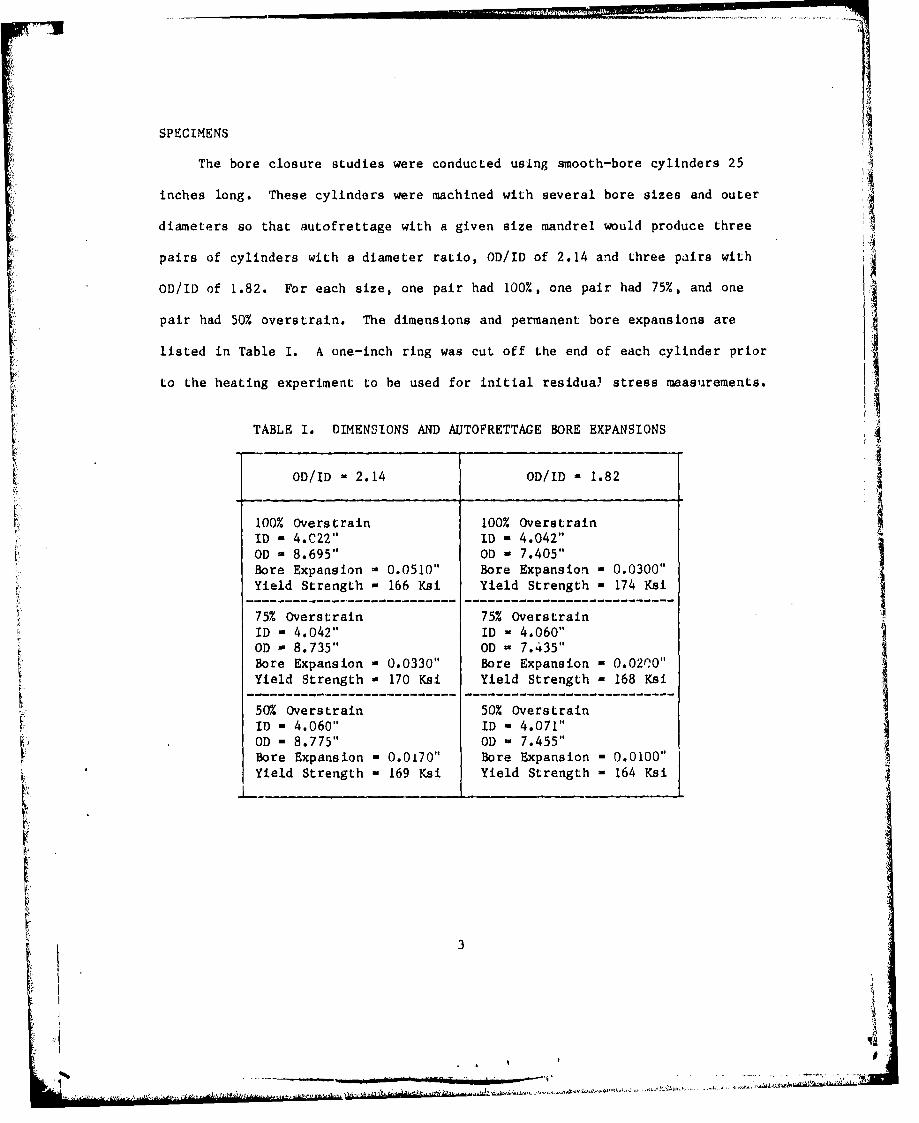
SPECIMENS
The bore closure studies were conducted using smooth-bore cylinders 25
inches long. These cylinders were machined with several bore sizes and outer
diameters so that autofrettage with a given size mandrel would produce three
pairs of cylinders with a diameter ratio, OD/ID of 2.14 and three pairs with
OD/ID of 1.82. For each size, one pair had 100%, one pair had 75%, and one
pair had 50% overstrain. The dimensions and permanent bore expansions are
listed in Table I. A one-inch ring was cut off the end of each cylinder prior
to the heating experiment to be used for initial residuaý stress measurements.
TABLE I. DIMENSIONS AND AUTOFRETTAGE BORE EXPANSIONS
OD/ID 2.14 OD/ID - 1.82_ _
100% Overstrain 100% Overstrain
ID - 4.C22" ID - 4.042"OD - 8.695" OD - 7.405"Bore Expansion - 0.0510" Bore Expansion - 0.0300"Yield Strength - 166 Ksi Yield Strength - 174 Ksi
75% Overstrain 75% Overstrain
ID - 4.042" ID - 4.060"OD - 8.735" OD - 7.435"Bore Expansion - 0.0330" Bore Expansion - 0.02,O"Yield Strength - 170 Ksi Yield Strength - 168 Ksi
50% Overstrain 50% OverstrainID - 4.060" ID - 4.071"OD - 8.775" OD - 7.455"Bore Expansion - 0.0170" Bore Expansion - 0.0100"Yield Strength - 169 Ksi Yield Strength - 164 Ksi
R! 3
btie.gaa ,.0

PROCEDURE
For the purpose of heating, a large blowtorch was utilized as shown in
Figure 1. A stainless steel cone was bolted to the specimen for concentrating
the flame into the bore. This procedure produced nominal bore temperatures
(Ta) of 950°F at the hot end station, 730'F at the mid-length, and 650°F at
the exit end station. Cooling was accomplished by means of an externally
mournted perforated coil.
I .. vW W;,. , . i,
S.; ': "L. •.
Figure I. Henting and Cooling Arrangement
4

The outside surface was cooled by either convection or using a coil for
air-water mist or a water spray. Four test conditions were used, giving four
ranges of temperature difference, AT, between the ID and OD: (1) up to 100*F
with natural convection cooling, (2) from 100CF to 300*F with forced air ccol-
ing, (3) from 300*F to 450*F wit:h air-water mist and (4) from 450°F to 800*F
with water spray cooling. The conditions were maintained for 15 minutes.
TemDerature measurement was obtained during the heating-quenching
operation by means of continuously measured chromel-alumel thermocouples,
welded to the OD surface and at two depths in the cylinder wall, mid-thickness
and 1/4 inch from the bore surface.
One inch thick rings were cut from the three stations for residual stress
measurement; these rings being located at 5, 12.5, and 20 inches from the hot
end of the specimen. Residual stress measurement was performed by slitting of
the rings and measuring punch mark separation, by SR-4 strain gages mounted
adjacent to the slit, and by measurement of angle of slit opening. The strain
gage approach is felt to give the most accurate measurement of stress relief aL
the cylinder surfaces.
While the angle of opening can be measured repeatedly to insure accuracy,
* the stress relieved is calculated from the angle by substitution into equations
relating the stress to the moment required to close the gap in a curved beam.
This permits calculation of stress values for any desired radii, but does not
give the actual stress relieved at a particular point in the cylinder wall.
For purpose of comparison, several rings from autofrettaged, non-heated
cylinders were exposed to steady state uniform furnace heating.
5
VJ61_ I
--------r -. ....
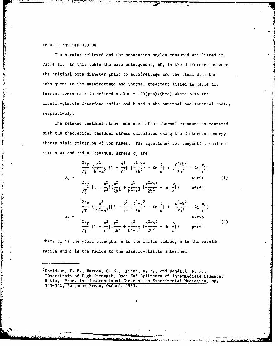
RESULTS AND DISCUSSION
The strains relieved and the separation angles measured are listed in
Tab.,e II. In this table the bore enlargement, AD, is the difference between
the original bore diameter prior to autofrettage and the final diameter
subsequent to the autofrettage and thermal treatment listed in Table 11.
Percent overstrain is defined as %OS - 100(p-a)/(b-a) where p is the
elastic-plastic interface rac•ius and b and a the external aod internal radius
respectively.
The relaxed residual stress measured after thermal exposure is compared
with the theoretical residual stress calculated using the distortion energy
theory yield criterion of von Mises. The equations 2 for tangential residualfil
stress a6 and radial residual stress Or are:2 ay a 2 b2 p 2 -b 2 p] 2 .b] p
+-- -I n + -[ nnr: b -a[ r 2b a -2b- r
OeE 0 a~r~p (1)20y b2 p2 a2 p-b 2 p
1+-1--- +------ [---I- ------- } p'~r~ir3 r2 2b2 b 2-a 2 2ba2
2ay -a2 - b 2 p2 -b 2 p2] 2 -b 2
r3 b -a2 r 2b a b2-1 r
Or a~rp2 0y b2 p2 a 2 P2-b 2 p (2)
-- [ -a (-21{-- +------- ---- 1 p~r~br3 [i r 21" b 2-a 2 "2b. a
where Oy is the yield strength, a is the inside radius, b is the outside
radius and p is the radius to the elastic-plastic interface.
2Davidson, T. E., Barton, C. S., Reiner, A. N., and Kendall, D. P.,"Overstrain of High Strength, Open End Cylinders of Intermediate DiameterRatio," Proc. 1st International Congress on Experimental Mechanics, pp.335-352, Pergamon Press, Oxford, 1963.
6

TABLE lHa. STRAINS RELIEVED ANU SEPARATION ANGLES
OD/ID - 2.14
Bore Strains Separation Punch MarkEnlargement Relieved Angle Separation
JType (in.) Ae (P in/in) (deg.) (in.)
100% os AD ID OD y OD
Unfired 0.0510 +4213 -1927 3.90 0.325
Ta - 648"F 0.0464 - -
AT - 422Ta - 736 0.0451 +3477 -1920 - 0.245AT - 541Ta - 932 0.0362 +2288 -20 1.85 0.130AT - 673
75% OS
Unfired 0.0330 +4953 -1!47 3.63 0.280
Ta - 685*F 0.0295 ...AT - 490Ta - 760 0.0289 +4152 -1156 3.30 0.230AT - 516Ta - 947 0.0176 +2700 -654 2.08 0.160AT - 726
50% OS
Unfired 0.0170 +4357 -1104 2.96 0.200
Ta - 638*F 0.0143 - -.
AT - 418Ta - 733 0.0142 +3295 -1387 2.66 0.175AT - 456Ta - 969 0.0079 +144 -145 1.56 0.095AT , 740
7

TABLE Ilb. STRAINS RELIEVED AND SEPARATION ANGLES
OD/ID - 1.82
Bore Strains Separation Punch MarkEnlargemenL Relieved Angle Separation
Type (in.) AF; (P in/in) (deg.) (in.)
100% os AD ID OD y OD
Unfired 0.0300 +4870 - 5.25 0.315
Ta - 656*F 0.0287 +4195 -3272 4.87 0.295AT - -
Ta - 793 0.0288 +3090 -2805 4.59 0.270AT -, 574Ta - 1123 0.0239 +957 -1441 2.20 0.295
AT - 802
75% Os
Unfired 0.0200 +4065 -2445 4.42 0.260
Ta - 641*F 0.0198 +3745 -2325 4.37 0.250AT - 409
Ta - 798 0.0190 +3117 -1698 3.85 0.245AT - 532Ta - 956 0.0149 +861 -1552 2.80 0.160AT - 726
50% OS
Unfired 0.0100 +1523 -1708 3.60 0.170
Ta - 650*F 0.0098 +2903 -1045 3.38 0.175AT - 466Ta - 745 0.0090 +2818 -1552 - 0.165AT - 452Ta - 939 0.0070 +1567 -887 2.00 0.110AT - 722
IIii i ii ii__ __ _ ______ _____ ______ _____ _____elk-

i- 'I
The tangential residual stress oe is of main intevest because of the
beneficial effects of compre'sive residual stress o0 at the bore, which
results in enhanced resistance to yielding and to fatigue.AICalculation of the stress relieved by slitting the rings, using strain
gage measurements, employed the uniaxial stress-strain relationship
an- E(ce~)
where E is 30x10 6 psi and Ace is the change in strain measured with a
tangential strain gage in microinch per inch.
From the angle y of opening of the ring at the slit the residual stress
is calculated by means of the moment M required to close the gap to form a
closed ring. The ring is assumed to act elastically as a curved beam and to
require a pure bending moment on the slit surface. 3 'Phis moment is given by
yE (b 2 -a 2 ) 2 - 4a 2 b2 (9.n(b/a)) 2-- [. . . .. . . . . .. . . . 1 (3)8 " Tr2(b
2 -a 2 )-(
The stress at any radius r is then calculated from I-4H -a b2
00- --- I--- r n(b/a) + b22£n(r/b) + a 2 Xn(a/r) + b2-a 2] (4)N
-4M -a 2 b2
ar .--- [-----n(b/a) + b 2 Xn(r/b) + a22n(a/r)] (5)
N r
where N - (b 2 -a 2 ) - 4a 2 b2 (Xn(b/a)) 2
a ib the radius to the inside surface and
b is the radius to the outside surface.
3 Timoahenko, S. and Goodier, J. N., "Theory of Elasticity," Second Edition,McGraw Hill, NY (1951), pp. 60-69, Third Edition, McGraw Hill, NY (1970),pp. 68-80.
9
*44
I'll . . .
__ ' .
Equations (4) and (5) do not apply for cases other than 100% overstrain, hence
further analysis is necessary to evaluate the stresses in partially
overstrained cylinders.
The following graphs show the expected and measured residual stresses,
bore closure and their variation with thermal gradient test conditions in
cylinders of two diameter ratios, 2.14 and 1.82.
Figures 2 and 3 respectively show the theoretical distribution of
residual stress for 2.14 and 1.82 diameter ratio, for percent overstrains of
25%, 50%, 75%, and 100%.
Figure 4 shows the temperature distribution through the thickness of the
cylinder wall. The data points are for forced air cooling of the 2.14
diameter ratio cylinder. The curves are plots of the theoretical logarithmic
steady-state temperature distribution4 calculated for the temperature
difference AT which was measured between the ID and OD with imbedded
thermocouples. The good agreement between data points and theory indicates
that the test conditions were close to the steady-state. This thermal
cundition produces an associated stress distribution of the same shape as that
for 100% overstrain, with compression at the bore and tension at the OD that
increase with increasing AT.
4 Kreith, F., "Principles of Heat Transfer," International Textbook Co.,
Scranton, PA, 1958, pp. 25-29.
- -S10 t
di
* V ---
--1
Lr)
/1 7
Ci /
r) 7U5 T
7-4/
/ /•
I" ///
S,~ */ //,
I-.- ? .' / 3. //CIS//
' V \ON M!3E3 FHEC *HS• " HE$V_:U~L qTHE53 [157 -"T1•
Fig. 2. Residual Stress versus Radius, OV/ID =2.14
, -...

I K .
//
L.-1 -... . .. I T,E`• I // RL5 ) S
0 / //i, R-s dua .
12/*1 "
" /~//
I2 " //
•7--,,'
~ R EBiDJaL 3T,•E%5 DCi-rBUT12.N
--. 8 D . = -,. T,
EA["LI (i INCHE5,
Fig. 3. Residual Stress versus Radius, OD/ID = 11.82
t 12
------ ------ ------ ------ ------ ------ -----
C)
F!.f I H .('ti~i 1 N(lli 15% {'z. c i t•<(i' HA IrI N
CC
I : L . c .•
Cl)
,. . .
L.U
FC -t _S t*IN~-L•
P19., 4. Tempoerature Ditztributlon, ODIID ?-214tL.for the forced air cooling condition.
13

I
I
Figure 5 shows the measured bore closure and its dependence upon the .
temperature difference AT between the ID and OD for the three bore
temperatures which were measured at the front hot end, the mid-length and the
rear exit end of the cylinders. The data points are plotted at increasing AT
values corresponding to the progressively increasing cooling of natural
convection, forced convection, afr-water spray, and water spray. The curves
may be approximated by an equation of the form y - A(I-eB(AT)). For example,
with a bore Lemperature of 730°F the approximation is expressed by
BC - 0.O0 6 (I-e-.O165(5/9AT)), where BC is bore closure in inches and AT is in
degrees Farenheit. b
It is apparent that the bore closure rises rapidly with small increase in
AT but approaches a limit asymptotically as AT is increased beyond 200°F.
This graph is for 100% overstrained cylinders of the 2.14 diameter ratio. In
this case the limit is 0.006 inch for the bore temperature of 730*F. For the
950*F bore temperature the limit is more than twice as big.
Figure 6 shows a similar dependence ui bore closure on AT for the 75%
overstrained cylinders of 2.14 diameter ratio. This data did not show the
well defined asymptotic nature seen in Figure 5. Also, the bore closure
corresponding to any AT is much smaller, by a factor of about one-half at AT
of 200*F for instance, than those for 100% overstrain.
Figure 7 shows bore closure versus AT for the 50% overstrained cylinders
of 2.14 diameter ratio. These measured bore closures are not much different
from those in the 75% overstrained cylinders. Thus, reduction from 75% to 50%
overstrain does not significantly reduce the bore closure for this diameter
ratio.
14
WK,

c---
/
- /
S• ' EY_TD [u,7 2 CV4
DE L T )TEOMP G' F
F. 5. B . --
//15
-u. : r-: • •''2, C• C': 4[; (Vi O r• . .
DELTA T (•1if DES F)
Fig. 5. Bore Closure versus Delta T, 100% Overstrain, OlD/ID 2.14
15
K E I
-I KEY.__gOD/I 2=2. 14
'- 7cZ OVEPSTFP' NL_2z `0 F)E TEMF::g9 o F
,- 0 5ORE fE Mi%, 30 F
-E I
~16
[ . • _ F -.
"-**-u-'.• ' "C C~ -Bir"/T
Ctosure == ,essDlaT 5 vesriO/D*21
16
._____, , ...-

P:
C) 0 BR EP-5
:7)
DELBOR TEM5 F)1 DGF
Fi.7 oeCouevessDlaT 0 vcsriO/D 21
C17
Figure 8 is a graph of the bore closure dependence on AT for 100%
overstrained cylinders of the 1.82 diameter ratio, plotted for the hot end,
the mid-length and the exit end bore temperatures. For this diameter ratio
the maximum bore closures measured at AT near 6000 F, corresponding to water
cooling, are about 0.006 inch, while those at the lower bore temperatures are
much less than that. Thus, the bore closures in the 1.82 diameter ratioI
cylinders are less than half as large as those in t1 ie 2.14 diameter ratio
cylinders.
Figure 9 showo similar results for the 75% overstrained cylinde:s of 1.82
diameter ratio. For bore temperatures less than 7300 F the bore closure is
very small.
Figure 10 shows similar results for the 50% overstrained cylinders of
1.82 diameter ratio. The maximum bore closure was only about 0.0)03 inch even
at the 950*F bore temperature.
Figure 11 is a plot of bore closure versus percent overstrain for a given
AT of 200*F in the cylinders of 2.14 diameter ratio. The large increase in
bore closure for percent overstrain greater than 75% is readily apparent here
for each of the three bore temperatures. This is attributed to the larger
amount of yielding during heating because of the greater depth and magnitude
of LID compressive residual stress and the larger OD tensile residual stress in
the 100% overstrained cylinders, see again Figure 2.
18
CDI
L* 0
CD.
K0-A C.A
Ofl
0 4-)
C-- LL, LLi -LjCD.LIJ
LuJ Llu LLuý
Cr-) z0 -- El) (2
a ii i Cr '>- CCL.CL.
00 '6 'Y 00(HJN~ 01 HIS -I AH
L ~CD7'WW19

0
00LL
0
X~ 0
Z Y- 4-)
>N fL- Ll) Cqif)
>,~~ LLLj L
0 iLIii liCu~.~ -,, w1 uL i Mu
U-) C t3oE
C)
O0s 0 e 06 09 0 00
020
... ...

CC)
5LCD
ZLLLLU r
cT C) CD CD C -1
-C)(Co u- Mr m)o
IV) 11 11 114-
U-11LULJLJ X-LYJ CO
c-) W co,
CD LJLJ JC\J 0-4cr- .rrcrc
ED~. F-I C-) 0A
00 21 Ln 6 d2100
(H:)N~~ ~ ~ ~ o ,ino 3 ýP

I' ~ ,-,'.~co
LL LL L- i-
4) 0
0 1)
1 AQ
Q~ ~i..22

Figure 12 is a plot of bore closure versus percent overstrain for
one-inch thick rings which were subjected to furnace heating for two hours at
each of the suceessive temperatures from 600*F to 1000*F shown. These rings
were cut from cylinders of 2.14 diameter ratio after autofrettage. Note that
the bore closure scale on this graph is 1/5 that on Figure 11. These graphs
indicate that the thermal gradient for a AT of 20' .epresented in Figure 11
causes bore closures about five times greater for the 100% overstrain and
about three times greater for the 75% overstrain than did the uniform
temperature from two hours of furnace heating represented in Figure 12.
The effect of such bore closures is not only to constrict the cylinder
opening, but to reduce the residual stress levels by r2laxation. The residual
stress remaining was measured by slitting rings from the three locations in
the cylinders.
Figure 13 is a graph of the ring separation angle ratio plotted versus
percent overstrain. The ratio is formed by dividing the separation angle
measured after slitting a riig of the partially overstrained specimen by the
theoretical angle for 100% overstrain. From Equations (1), (3), and (4) the
theoretical angle is found to be expressed in degrees by:
8lrOy 360"Y1oo04 --- I(---)
r3 E '2 n
and is theoretically independent of the diameter ratio OD,0ID of the ring.
Here ay is 170,000 psi and E is 30x10 6 psi, hence Y100% - 4.,10 degrees.
The upper data points were obtained from the separation angles of rings
of 1.82 diameter ratio after slitting. The lower data points were obtained
similarly from slitting rings of the 2.14 diameter ratio, and the single data
23
L%,•.•,%]. . ... , ,, ,
CDILL- LI P64LLI
C, Cr, Lf
0 0
IL
24

X coLLJ X0
u ~j:: rT c 4)o-
I-~ 4- *f C O /
wLL ii o 0)
CE: C: 0 0 CE .4
.o M
CD Y- Y-Lo -) 1J~.4m
~cjcJ n Cc' 0
ci U) 0 - L A 6.U
CD co m
El E) I Z C) O-4r- -0 L x
-40i
~~1-~ Icc.
4--
V')

point from a 100% overstrained eight inch tube was from a ring of 2.09
diameter ratio. These are compared with a curve from an analysis by A. P.
Parker 5 which expresses the ratio of the moments, "PA for partial overstrain
4. and Ml(() for 100% overstrain, required to close the angular gap resulting from
slitting rings of 2.00 diameter ratio. The analytical curves for all other
diareter ratios discussed here should be within 1% of that shown in Figure 13.
The ratio of the separation angles predicted by analysis should be the same as
the ratio of the moments.
Comparison of the experimental results with the curve for 2.00 diameter
ratio indicates that there is a reiuction of angle as the diameter ratio
increases from 1.82 to 2.14. It is believed that non-ideal Bauschinger
effects of reverse yielding occurring during the autofrettage process account
for the discrepancies between the data and the analytical curve. Greater
tensile yielding and more reversed yielding would occur at the bore of the
larger diameter ratio cylinders during autofrettage, resulting in less than
expected residual stress. The discrepancy from the theory is greatest at 100%
overstrain, which is logical because the biggest Bauschinger effect should
accompany the largest overstrain. This discrepancy at 100% overstrain is even
more pronounced in the graphs of residual stress obtained from strain gage
data which are shown in Figures 14 and 15.
5 Parker, A. P., Underwood, J. H., Throop, J. Y., and Andrasic, J. P., "StressIntensity and Fatigue Crack Growth in a Pressurized Autofrettaged ThickCylinder," presented in the ASTM 14th National Symposium on FractureMechanics on June 30, 1981, UCLA, Los Angeles, Ca.
26

LL L.LL ~LL. LCD CD CD CD
CDD CD CD 0 C) D
11 - -* F- 11 F- i() I
LJ Wr j UJ LiLB- Itub- -LL- trr~ flZ cri w2 )LI C)L LW I'D LL-j CD C
/ /4) 0
If o
cog- LF- 4-
co 4
3i-
U -4j
JL~D *~Jt O)* ~ ~ j0 013 *Os- 0) 03 -J .)OS: I o n olrjL
27

ft I--
Ii10 IL I.f IL
(Yn c- LfO( QD
t -L u-.
ti: ED1 ir~ IU-I-~D LU ii ('I
(Nic r-4 ~ i
00 wTM 4-U
00 00 00*1 0 0 0 O 0 ,00 1- 0o CLU CD C, r
AD uU - L4
28J c.
Figure 14 shows the theoretical variation of tensile residual OD stress
in the upper portion and that of the compressive residual bore stress in the
lower portion, plotted versus percent overstrain for cylinders of 2.14
diameter ratio. Experimental measurements of residual stress relieved at
strain gages next to the sawcuts when the rings were slit are also plotted for
the unfired as-autofrettaged cylinders and for the thermally treated
autofrettaged cylinders. At 100% overstrain the plot shows a large difference
between the theory and the unfired data, in both the ID and OD residual
stresses. The differences from theory are much greater than for the 75% and
50% overstrained cylinders. This is attributed to greater losses in the 100%
overstrained cylinders caused by the Bauschinger effect during the
autofrettage process.
It is also significant that at the elevated bore temperatures of 730*F
and 950*F and the AT corresponding to water cooling, large losses in residual
stress occurred in the 15 minute thermal exposure.
Figure 15 shows a similar graph of residual stress versus percent
overstrain for the 1.82 diameter ratio cylinders. Here there is no great
difference between the strain-gage measured residual stresses in the unfired jautofrettaged cylinders and the theory. However, the losses of residual
stress at the elevated bore temperatures and AT corresponding to water cooling
are just as severe as in the 2.14 diameter ratio cylinders. They indicate
that even for this smaller diameter ratio, water cooling of the hot cylinders
can cause large loss of autofrettage residual stresses in a few minutes.
29
______ ______
* S 4
-___,____.__,__________________.________.__________. ._____________
S. .. ... .. .,. ... . • •...... ,,.. . • • ., ........... .. . ...... ........ . . . . . .• ,,.•,.:: .• .

Figure 16 shows the residual bore stress ratio expressed by the ratio
(Go experimental)/(oe theoretical) for the 2.14 diameter ratio cylinders
plotted versus the bore enlargement ratio expressed by the ratio
(final bore enlargemenL)/initial bore enlargement for each percentage
overstrain.
The results from the unfired cylinders plot at the bore enlargement ratio
of 1.00 and show about 30% loss from the theoretical residual bore stress in
the 100% overstrained cylinders, about 15% loss in the 75% overstrained
cylinders and about 10% loss in the 50% overstrained cylinder.
At the elevated bore temperatures and AT corresponding to water cooling
the loss in residual bore stress is even greater, and is greatest in the 100%
overstrained cylinders. Note that data points for some test conditions are H" missing in Figure 16 due to experimental problems.
InformaLL ti such as in Figure 16 may provide a useful measure of thermal
damage to autofrettaged cylinders, permitting one to estimate how much of the
autofrettage residual bore stress remains in a cylinder after thermal treat-
ment or after prolonged firing and cooling in service. From measured bore
diameters before and after autofrettage and after thermal exposure one can
determine the bore enlargement ratio and from that estimate the ratio of
remaining residual stress to the theoretical autofrottage residual stress.
Figure 17 shows a similar graph of residual bore stress ratio versus bore
enlargement ratio for the cylinders of 1.82 diameter ratio. The results for
the unfired cylinders show very small loss in residual bore stress compared to
the theoretical expected values, as mentioned earlier in regard to Figure 15.
On the other hand, at the elevated bore temperatures and AT corresponding to
30
I • • I --l I I

CMD C-3 c DU)Lf') (T11CiD4
F-- aL LI 4)
(I-IID L w _i ( i
M CiDr r-rj-cl -
-j F- (
-D 0 co
/( c1 co~
CrT- Fcric~ M I-M'E-'C1
G -(I-. - /c t
7 Li 1-1i Lii cEC-3~ C-D .
~ If)CD L CCD
31
- ---- .-_ _ _ _ _ ------

ULL- L Lj. Lt
ti') C CD)f 0
F- F- F--- 0-
LU cr Cr- CD004 \m: LUJF- WjI,- C- I
cr.U ý j CLi -~ II -LL. 0w Ew U-1 0)
0 ()
4-) LO-~'57
U-1 9L0 4-) d)
M ED CD O 32
LP L.LCO 4
C:).&M~mt LL - '- -

V-=1N
water cooling a 25% decrease in bore enlargement ratio from 1.00 to 0.75 is
accompanied by an 80% drop in the residual bore stress ratio, not only for the
100% overstrained cylinders but also for the 75% overstrained ones. This
indicates that for the thinner wall cylinders water cooling of tubes from bore
temperatures near 1000*F may practically eliminate the autofrettage residual
bore stresses. At the 650°F bore temperature, however, the loss of residual
bore stress is only about 20% for a decrease of about 10% in the bore
enlargement ratio resulting from water cooling.OI
1. C n the presence of high th-rmal gradieits, residual stress relaxation
and bore closure can occur in large diameter ratio cylinders with overstrain
S~as low as 50%.
alo2. The magnitude of relaxation is significantly greater in the presenceI of thermal gradients as compared to uniform heating. This indicates that the
primary mechanism is reverse yielding due to the combined compressive
autofrettage residual and thermal stresses near the bore.
A 3. The magnitude of relaxation increases wita increased overstrain even
though there is little difference in actual compressive residual bore stress
between 75% overstrain and 100% overstrain.
4. The amount of bore closure increases with measured overstrain,
thermal gradient and bore temperature. The magnitude of residual bore stress ,
relaxation is a function of the initial residual btrnss level and is not
directly related to percent overstrain in cylinders of large diameLar ratios.
33
.-4."-----

REFERENCES
1. Dawson, V. C. D. and Jackson, J. W., "Investigation of the Relaxation of
Residual Stresses in Autofrettaged Cylinders," Trans. of ASME, Jour. of
Basic Engineering, Vol. 91, Series D, No. 1, pp. 63-66, March 1969.
2. Davidson, T. E., Barton, C. S., Reiner, A. N., and Kendall, Dý P.,
"Overstrain of High Strength, Open End Cylinders of Intermediate Diameter
Ratio," Proc. 1st International Congress on Experimental Mechanics, pp.
335-352, Pergamon Press, Oxford, 1963.
3. Timoshenko, S. and Goodier, J. N., "Theory of Elasticity," Second Edition,
McGraw Hill, NY (1951), pp. 60-69, Third Edition, McGraw HIll, NY (1970),
pp. 68-80.
4. Kreith, F., "Principles of Heat Transfer," International Textbook Co.,
Scranton, PA, 1958, pp. 25-29.
5. Parker, A. P., Underwood, J. H., Throop, J. F., and Andrasic, J. P.,
"Stress Intensity and Fatigue Crack Growth in a Pressurized Aucofrettaged
Thick Cylinder," presented in the ASTM 14th National Symposium on
Fracture Mechanics on June 30, 1981, UCLA, Los Angeles, Ca.
i34
( ~34j
.,.%g2' & tt. ~If,~l&.~ikAI4.Ž .,Ai . .

BCYSCSL3:TC ITERNAL DISTRIBUTI ON LI3)Tj
NO0. O!W
C~ ~ ~ ~ ~ ~ ~ H PIES!~'-I\G PpC
o .. 2¶ N : B1
UH•?K~~tPEŽ 7N TME'RJ C J7"tCH
A TTý 1 P. Y ,-1 LI
1Y1
AWN: ~ ~ -A EPA-CDPA
-kTG DTRI? 1AT
AnN D A-LC ATN

TFClN ICAL REPORT FiXTERNAL D)I STR IIBUTI ON LI ST
NO. OF NO. O1CO P I ES COP 1J J.E
ASST Sl:V O11 Till: ARMY COMMANI)ERRI:SEARCIl 6; I)IA'EIOMENT US ARMY TANK-AtJTMV R&ID COMDATTN' lEP FOR SC1 & TICII 1 ATrT : °lB'lI 1,1]B - DRDTA-UI, ITII PENTAGON MAT ILAB - DRDTA-RK IWASHINGTON, 1).C. 20315 WARREN, MICIII(CýN 48090
C;OMMANIDER COMMAN[DIR(IS ARMY MAT DI:V F& REAl). COMD US MILI I'ARY ACIADEMYATTN llRCtDE I ATTN: CIIMN, MECH ENGR DIFPT5O01 I EISENIIOWIIR AVE WEST POINT, NY 10996AIIiXANDRIA, VA 22333
US ARMY MISSILE COMDCOMMANDIR REDSTONE SCIENTIFIC INFO CEN(IS ARMY ARRAICOM ATTN: DOCUMENTS SECT, BLDG 4484AiTTN: I)RI)AR- IC I REDSTONE ARSENAL, AL 35898
- IA (PL ASTI 1CS TECH 1EVAI. CEN) COMMANDER
- LCX REDSTONE ARSENAL- LCM 1 ATTN: DRSMI-RRS I- ILCS 1 -RSM 1- ICW 1 ALABAMA 35809-TSS (STINFO) 2
)OVEiR, NJ (7801 COMMANDI'RROCK ISLANID ARSENAL
COMMANDER ATTN: SA.P,'I-ENM (MAT SCI DIV) 1Us ARMY ARRCOM ROCK ISLAND, IL 61202ATTN : I)RSAR-ILEP-1,ROCK ISLAND ARSENAL COMMANDERROC:K ISLAND, IL 01299 HQ, US ARMY AVN SCH
ATTN: OFC OF THE LIBRARIAN ID}Il R 1:':OlR FT RUCKER, ALABAMA 36362IIS ARMY BALL.ISTIC RESEARCHI LABORATORY
ATTN: ' DRDAR-'rSB-S (STINFO) 1 COMMANDERABIIRDEEN PROVING GROUND, MD 21005 US ARMY FGN SCIENCE & TECH CEN
ATTN: DRXST-SDCOMMANDER 2 2 L, 7TH STREET, N.E,UIS ARMY EXLCTRONICS COMD CHARLOTTESVILLE, VA 22901ATTN: TECH LIBFT MONMOUTH, NJ 07703 COMMANDER
US ARMY MATERIALS & MECHANICSCOMMANDER' RESEARCH CENTERUS A.MY MOBILITY EQUIP R&D COMD ATTN: TECH LIB - DRXMR-PL 2ATTN: TECH LIB 1 WATERTOWN, MASS 02172FT BELVOIR, VA 22060
NOTE: PLEASE NOTIFY COMMANDER, ARRADCOM, ATTN: BENET WEAPONS LABORATORY,1)RDAR-LCB-TL, WATERVLIET ARSENAL, WATERVLIET, N.Y. 12189, OF ANYREQUI RED CHANGES.
TE.CIHNICAL REPORT EXTERNAL DISTRIBUTION LiST (CONT.)
NO. OF NO. )FC OPT E ClP
C, 1.11A NDER C I-IQAN DER-K7IS AiY R1'2-).AfICH OFFICE DEFENSE TECHNICAL INFO CE4TERP.O. BM 12. 2. 1 ATTN: DTIA-TCA 12R i`EARCH TRU:NCLE PARK, NC 27-709 CAMERON STATION
ALEXANDRIA, VA 22314C iIIA,°A NDER1US ATv1Y HAR>:d' DTA•ONb jAB METALS & CERAMICS INFO CEN
A7TN: TECH LIB 1 BATTELLE COLUMBUS LAB2'flO P(NYDER AILL ROAD 505 KING AVEAllIPHtA, I M0783 COLUMBUS, OHIO 43201
: 1RECTOR MECHANICAL PROPERTIES DATA CTRUS ARvMY INDULSTRIAL BASE hNG AC¶1 BATTELLE COLUMBUS LABATTN: DRXP`-IMT 1 505" KING AVERCI',K ISLAND, IL 61a01 COLUMBUS, OHIO 43201
CHIEF, MATER1AIS BRANCH MATERIEL SYSTEMS ANALYSIS ACTVIS APJIY R?33 2?OIJP, itIR 1 ATTN: DRXSY-NTI(Ba 65, FPO ',.Y. 09510 ABERDEEN PROVING GROUND
MA RY LA ND 21005C (1.,'A NDERNIAVAL SURFACE WFAPONS CENAT*TN: CHIEF, MAT SCIENCE DIV 1DAHL43REN, VA 22448
D I RECTORUS NAVAL RES FARCH LABATTN: DIR, ,,ECH DIV 1
CCrE 26-27 (DOC LIB), 1WASHINGTON, D. C. 20375
NASA SCIENTLFIC & TECH INFO FAC.P. 0. BOX $757, ATTN: ACQ BRBALTlAORF/VW.3HINr,TCN INTL AIRPORT
.,lARYIAND 21240
NOTE: PLEASE NOTIFY C(IMANDER, ARRADCCM, ATTN: BENET WEAPCNS LABORATORY,DRrA.-LCB-TL, WATERVLIrT ARSENAL, WATERVLIET, N.Y. 12189, OF ANYREQUL--ED CHANGES.
' •<Ii'i' moo---