Embed Size (px)
Citation preview

I.CHEM.E. SYMPOSIUM SERIES NO. 97
THERMAL RADIATION HAZARDS OF LIQUID POOL FIRES AND TANK FIRES
w.P. Crocker* and D.H. Napier*
Three models for the prediction of thermal radiation from liquid pool fires and tank fires, are considered. These models are used with appropriate viewfactors to compute the radiation intensity profiles from tanks and pools of various dimensions and subjected to the effect of wind. Damage criteria are used as a basis of comparison of the profiles and of those with safety codes. From this study appropriate models are recommended.
Key Words: Radiation; Hazards; Liquid fires; Pool; Tank; Viewfactor.
INTRODUCTION
Pool fires and tank fires of flammable liquids occur in a variety of situations, the detail of which determine the amount of damage that results and the rapidity with which fire-fighting measures can be brought to bear. Pool fires within processing areas may be of fairly well-defined dimensions, eg. in a bund or within a kerbed area. Such fires arising from loss of containment during transit, can cover a wide range of dimensions the upper limit of which may be forecast. Tank fires are, under worst conditions, of known dimensions. The need to estimate the magnitude of the thermal radiation hazard from such fires is of importance in the context of the emergency per se and of their effects on their surroundings. Thus other storage tanks and vessels and both buildings and people within and outside the factory fence are subject to hazard that requires assessment.
If containment of a flammable liquid is lost and the consequent vapour-air mixture is ignited, estimation of radiation from the thermal radiation generated depends upon a number of factors which include:
fuel-type and burning rate propensity to smoke formation, flame emissivity heat of combustion flame length and its relation to the dimensions of the surface of the fuel
transmissivity of the surrounding atmosphere proximity, dimensions and nature of receptors effect of wind causing flame tilt.
* Department of Chemical Engineering and Applied Chemistry, University of Toronto, Canada MBS 1A4

I.CHEM.E. SYMPOSIUM SERIES NO. 97
In this paper, models of thermal radiation from both pool and tank fires will be considered as aids in layout and in preparation of contingency plans. For a variety of reasons these models do not generate separation distances that are in total agreement and these predicted values are often at variance with values set down in codes and standards. The models or adaptations from them have been run in order to generate comparative design information. From these investigations certain models emerge as preferable in one or another application.
However, before examining the models, certain basic aspects of the fire system have to be selected as a basis from which to work. These are: burning rate, flame length correlations and flame tilt correlations. From this basis the models have then been investigated.
BURNING RATE
The work of Blinov and Khudiakov (1) and the related work of Hottel (2) are well-known. Equally so is the correlation due to Burgess and Zabetakis (3). This latter has been used here with values of m^ by Babrauskas (4); the mass burning rate, m" is given by
where
m" = m
m is 1 x 10
l-exp(- K'3D))
-3 AH . -2-1 c kg m s
:D
and
in which
AH* = AH + v v
<8 extinction coefficient x mean beam length corrector
AH heat of combustion (kJ kg" )
b Cp(T) dT
T o
AH is the heat of vaporisation at the boiling point (kJ kg" )
T, normal boiling point (K)
T ambient temperature (K)
C (T) specific heat (kJ/kg K) P 1
AH heat of combustion (kJ kg" )
FLAME LENGTH CORRELATIONS
Correlations due to Thomas (5) and Heskestad (7) have been used in this paper. The first of these is:
0.61 (2)
where
L = 42D m" v'gTJ
L is mean flame length (m) D pool/tank diameter (m) c ambient air density (kg m -3,
-2 - 1 \ m" mass burning rate per unit area (kg m s ) g 9.81 m s " 2
The second was developed to predict the mean luminous height of buoyancy-controlled, turbulent diffusion flames. It was expressed as
160

I.CHEM.E. SYMPOSIUM SERIES NO. 97
L = D(-1.02 + 15.6N1/5) [3)
where
and
N =
-1
Q is tota l heat release rate, i e . mfrf (kW)
m mass burning rate (kg s )
AH heat of combustion per uni t mass (kJ kg 1 1 C specif ic heat of a i r (kJ kg K )
T ambient temperature (K)
r stoichiometric mass ra t io of a i r to vo la t i les -3
p ambient air density (kg m ) D diameter of source (m)
For liquid fuel of formula C H.O burning in air a 6 Y
r = 137.87 (a + B/4 - y/2) b (12a + 8 + 16Y)
Correlations (2) and (3) apply to s t i l l - a i r conditions, a wind is blowing, Thomas (6) has given
where
and
i f
L = 5
U §B
0.67u 0.21
(4)
For si tuat ions where
(5)
is dimensionless wind velocity, U U
wind velocity (ms ) characteristic wind velocity
U < U , II* was assumed to be equal to unity.
gmTJ po
1/3
FLAME TILT CORRELATION
The correlation of Welker and Sliepcevich (8) has been used to predict wind-engendered tilt, viz
where
tan 9 _ 3.3 Re°-07Fr° COS 0
8
Re is Reynolds Number,
Fr Froude Number, it
Po.
ie
%
-0 6
D(m)U(ms_1)po(kg m"3)
y0(kg nfV1)
U2
(6)
M0 -3, viscosity of ambient air
density of fuel vapour at normal boiling point (kg m"°)
deflection of flame from the vertical
161
I.CHEM.E. SYMPOSIUM SERIES NO. 97
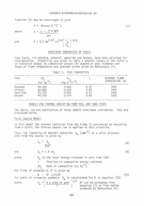
Equation (6) may be rearranged to give
6 = Arccos l/~x~ ]
where x = -1 + .1 + 4F2
(7)
and
2F2
F = 3.3 Re0"07 F r 0 ' 8
. P o j
-0.6
PERTINENT PROPERTIES OF FUELS
Four fuels, viz benzene, ethanol, gasoline and hexane, have been selected for consideration. Properties are given in Table 1 wherein values of the ratio n, of radiative output to combustion output (9) depend on pool diameter and those of flame temperature are average values given by Babrauskas (4).
FUEL
Benzene Ethanol Gasoline Hexane
(kJ kg x)
40,100 26,800 43,700 44,700
TABLE
MODELS FOR THERMAL
1: FUEL PROPERTIES
m
(kg m'V1) 0.085 0.015 0.055 0.074
RADIATION FROM POOL
n
0.37 0.20 0.13 0.40
AND TANK
AVERAGE FLAME TEMPERATURE (K)
1460 1490 1450 1300
FIRES
The basis, use and application of three models have been considered; they are discussed below.
Point Source Model
In this model the thermal radiation from the flame is considered as emanating from a point; the inverse square law is applied to this situation.
Thus, the intensity of thermal radiation q (kWm x(m) from the source is given by
-2. at a point distance
and
where
*r" Qr
Qr = n m AHC
Q is the total energy released in unit time (kW)
n fraction of combustion energy radiated
AH heat of combustion (kJ kg- )
For fires of diameter D, m is given by
m = m" (TT/4)D2
For pools of irregular geometry D is substituted for D in equation (10) f 1'2 •
D = 4 x area of pool , ' m" can be estimated from IT J equation (1) or from tables
produced by Babrauskas (4).
where
(8)
(9)
:io)
162

I.CHEM.E. SYMPOSIUM SERIES NO. 97
From Figure 1 (10) the thermal radiat ion at ground level from a tank f i r e is given by
% = ^r C0S.^ (11)
where I|J is the angle between the incident ray and the horizontal
r distance from the point source to the target (m).
Equation (11) may be developed using the dimensions given in Figure 1, to yield
q . = Q x yr
4IT[(H + i ) 2 + x2] :i2)
where H is tank height (m)
L is flame height (m)
Solid Flame Model
The diagrams in Figure 3 depict this model in which the flame is represented as a solid cylinder with uniformly radiating curved surface. Whence the Stefan-Boltzmann equation may be applied if an average flame temperature,Tf, and uniform emissivity, e, are assumed. Then
= F A rf->tgt Hf rea (T. - T 13)
where f-*tgt
is the viewfactor, ie. the fraction of radiation
leaving the flame that is incident upon the target
area of the flame "seen" by the target (m2)
atmospheric transmissivity (taken here as unity)
Stefan-Boltzmann constant 5.676 x 10"nkWm"2K"4
ambient temperature (K)
Using e = l-exp(- KD ) with values of K, the extinction coefficient, given by Atallah and Allan (12), the emissivity has been taken as unity.
Viewfactors for Solid Flame Model
The usefulness of a prediction of thermal radiation depends in large part upon the closeness with which the viewfactor describes the geometry of the flame and the receiver.
In the computations reported here, two viewfactors were used relating to a windless condition for an upright cylindrical flame. The first of these factors was that due to Morgan and Hamilton (15); Figure 3 illustrates the geometry. The viewfactor, F, is given by
F = 1 tan TfS
where
-1
/S2 - 1
R = D/2
S = x/R
I = 9/R
+ L [A - 2S) tan_1/A(S - 1) - 1 tan"1.
S/SB- '6(S + I! S~T - 1 I
:i4)
163

I.CHEM.E. SYMPOSIUM SERIES NO. 97
A = (S + l) 2 + L2
B = (S - l) 2 + L2
The second (14) which yields more conservative results based on the solid angle subtended at a point, is
F = 2 s i n " 1 D 7x
sin tan" 1 L
ir^un :i5;
Using the Reciprocal Theorem, these viewfactors have been used in equation (13) of the Solid Flame Model. Unit area (1 m2) is assumed for the target element.
Pool fire. Determination of radiation profiles may be made by direct use of either equation (14) or (15) in equation (13).
Tank fire. In the context of Figure 3, three targets arise for consideration, viz storage tanks, buildings and people. The viewfactor must be determined accordingly. Thus for storage tanks, if adjacent tanks are of the same height, maximum intensity of radiation is received at target 2 (Figure 3). The calculation of this intensity is identical to that for the ground level pool fire.
For buildings that are taller than the total height of the tank fire, the maximum intensity is at target 3 (Figure 3), ie. opposite to the mid-point of the flame. The subsequent estimation is based on a datum through the midpoint of the flame. The viewfactors (equations (14) and (15)) may be used as before; the numerical value must be doubled to take account of the bottom half of the flame. Intensity can then be calculated using the Stefan-Boltzmann equation.
Consideration of radiation incident upon people is usually concerned with those on the ground. Of the tank-flame system, radiation from the tank can be ignored so that q at target 1 (Figure 3) is given by
qr = [F(x,L + H) - Ffx.H)] o (Tf4 - T Q
4 ) (16)
Equivalent Radiator Model
This model was originally used by Seeger (22) for tank fires, but can be adapted to pool fires by putting H = 0. This treatment will be discussed later. The approximate viewfactor ER model given by Wells (23) based on Robertson's (11) work is described hereunder. Radiation which was assumed to be 30% of the thermal output of the flame, was assumed to be emitted from an equivalent radiator of dimensions D x 2D; the inverse square law was then applied.
The model was described in terms of the equations that follow: these are based on Figure 2.
Qr = 0.3 m" Mc (TT/4)D2 (17)
The emissive power of the flame qf is given by
f 2W
164

I.CHEM.E. SYMPOSIUM SERIES NO. 97
where the cylinder equivalent to the flame measures D x 2D. An approximate viewfactor was used to determine the intensity of radiation, q , at distance x from the tank and x, from the equivalent radiator; whence r
%- 2t£ (is:
where A' is the area of flame seen on the ground at the receiver, and A' = 2D x D cos ty
From the geometry of the tank
il> = Arctan D + H
and - D sin ii>
:i9)
;2o) cos \p
Viewfactor for Equivalent Radiator Model
In Figure 4, the Equivalent Radiator Model is depicted for a pool fire and a tank fire, each with both horizontal and vertical targets. The latter application is not uncommon. Two forms of a viewfactor originally due to Morgan and Hamilton (15) may be used in equation (13) and are
Horizontal target
F = 1 tan_1B - I tan -1
A + C2 /T+T2"
[2i:
Vertical target
F =
/nr tan -1 tan -I
ST+^r A + C2 -TTF :22)
where = R and C = L. x x
R, L and x are shown in Figure 4.
Practical Applications
Pool fires. Radiation may be calculated using either equation (21) or (22) and doubling F which refers only to area A?; account must also be taken of the effect of the other half, A,, of the equivalent radiator.
Tank fires. The geometry of the system is shown in Figure 4 and basis of calculation of the viewfactor is similar to that used with the Solid Flame Model. Thus with the doubling factor to take account of A, and A„
F = 2F(L + H,x) - 2F(H,x) (23)
Buildings. It will be deduced from Figure 4 that the position of maximum incident radiation on a vertical target (the building) is a perpendicular from the mid-point of the equivalent radiator. The viewfactor for the maximum intensity at the building then becomes
165

I.CHEM.E. SYMPOSIUM SERIES NO. 97
Fmax = 4F(R,L/2,x; (24;
If the target is horizontal, eg. the roof of either an in-ground tank or of a building less tall than the tank, the situation occurs which is shown diagramatically in Figure 5. The viewfactor obtained from the same general equation used for equation (21) is given by
12 1 7-
tan"1 ,1* + V(N cos 9 - L) tan l V
where N = a/b
L = c/b
V =
+ cos
1
tan -i N - L cos BN + tan" ,1 cos 9 TT TT
(25)
(N2 + L2 - 2NL cos
W = (1 + L2 sin2 0)*
Radiation intensities at the horizontal target are calculated by using equation (25) and introducing a variable B to account for the "pseudo-pool fire". The viewfactor for the flame alone becomes
F- = 2F(R, L + LI, B) - 2F(R, LI, B)
9 is the wind-induced flame tilt.
FLAME TILT MODELS
Pool fire. Flame tilt caused by wind extends the radiation hazard; the appropriate viewfactor is required for this system. An expression (14) for this factor is given in equation (26) which relates to Figure 6 and is for a point receiver.
F = 2 s IT
-1 (D/2)
ID/2) + (x - (D/2)) cos 9)
sin 9 + sin tan -1 L - tan
x - (D/2) cos
(26)
Curves have been produced for a set of values for tilt (17,18). In addition, an analytical expression for the viewfactor has been produced by Mudan (9) based on previous work by Raj and Kalelkar (16). The expression which applies to an element of area, is
+ B K A J COS <{> + h A21 F = 1_ [sin TT
If the target is vertical 3 = 90°, so that
F = 1 cos 9 (A, cos <J) + h A,
+ (A3 - A4) cos 6 ]
where
;A1 cos
is the angle of tilt
sin_1(l/S)
(27)
:28)
166

I.CHEM.E. SYMPOSIUM SERIES NO. 97
and
where
and
where
flame length in wind = L pool radius ft
5 dimensionless distance = x ft
A, is given by
A, = 1
*I tan
-1 h - (S - 1/S) sin 6
L + tan
-1
'1
(S - l/s) sin e
'1
Jj = [(S2 - 1) cos2e + (1 - 1/S2) sin2e ] J
A? is obtained from
A2 =
f(v) =
f(v)dv
sin v
(1 + h2 + S2 - 2Sh sin e) + 2(h sin e - S) sin v
A? must be integrated numerically; in the results given here the Trapezoidal Rule with 35 iterations was used to evaluate A?.
If the target is not vertical, then A^ and A. are required to evaluate equation (27).
A3 = (S sin v - l)dv
(1 + S2 - 2S sin v)
A4 = (S sin v - 1) dv
[(1 + h2 + S2 - 2h sin e) + 2(h sin 9 - S) sin v]
Tank fire. The geometry of this situation is shown in Figure 6. The approach taken has" been to extend the tilted flame of length L back to the ground whereby its length is increased by Lj. The centre of the base of this tilted cylinder is at a distance x\ upwind of the centre of the tank. By this means the tilted flame is considered as a pseudo-pool fire of which the section of length l_i does not radiate. The required viewfactor is
F(L,I = F (L + Lj,l - F(L rB) (29)
where F(L + L,,B) is the viewfactor for the pseudo-pool fire
Fdj.B] the viewfactor for the "extended" section of the tank fire.
F(L,B) was used in equation (13) and it has been calculated using either equation (26) or equation (28).
167

I.CHEM.E. SYMPOSIUM SERIES NO. 97
DAMAGE CRITERIA FOR SPECIFYING SAFETY DISTANCES
While tank fires and pool fires are subject to fluctuations due to, for example, wind and turbulence, they usually are of sufficient duration to be considered as attaining a steady state. Therefore, it is meaningful to refer to levels of intensity of incident radiation from such flames, in relation to hazard and separation distances. Extensive consideration has been given to these values of intensity (eg. 19,20,21) but the values used by Robertson (11) and shown in Table 2 will be used here.
TABLE 2: DAMAGE FROM VARIOUS LEVELS OF THERMAL RADIATION
TARGET THERMAL FLUX EFFECTS (kWm-2)
Human body 4.7 Threshold of pain. Average period for pain to be experienced 14.5 s.
Buildings 12.6 Resins in wood, building felt produce flammable vapours which could be ignited by pilot ignition
Storage tanks 37.8 Hazardous for a tank adjacent to a tank fire to receive this flux.
SPACING DISTANCES DERIVED FROM THERMAL RADIATION MODELS
In the tables that follow results are given for spacing calculated by the stated model, from pool-edge or tank-shell to the specified intensity of radiation. Pertinent values of other calculated quantities are also given. All of these results are reported without commentary, which is given in the discussion.
TABLE 3: RECOMMENDED TANK SPACINGS (S) based on 37.8 kWm"z incident radiation
(Thomas (5) L/D correlation)
FUEL TANK DIAMETER (m) Average RANGE OF S/D
Solid Flame Model (+ Morgan/Hamilton V.F.)
10 20 30 40 50
Benzene 11 Gasoline 10.1 Hexane 5.6 Ethanol 8.5
Benzene 9.5 Gasoline 8.4 Hexane 4.0 Ethanol 6
21 32 19 28 11 16 15.3 21.6
18 25.4 15.2 21.3 7.5 10.6 10 15
40 49 36 43.5 21 26 27.5 33
32.4 39 27 32 13.5 16 16 18
1.04 1.1 - 0.9 0.93 1.0 - 0.9 0.54 0.6 - 0.5 0.74 0.9 - 0.7
0.86 1.0 - 0.8 0.73 0.8 - 0.6 0.36 0.4 - 0.3 0.47 0.6 - 3.2
Equivalent Radiator Model (Vertical target) (22)

I.CHEM.E. SYMPOSIUM SERIES NO. 97
TABLE 4: RECOMMENDED BUILDING SPACING based on 12.6 kWm-2incident radiation (Fuel: Benzene Tank Height 15M)
TANK DISTANCE GROUND S/D S/D MODEL DIA.(m) TO Q m a v LEVEL TARGET Q GROUND
maX (oi) m a x LEVEL
10 32.5 * 3.25 0 1. Solid flame (M/H) 30.5 * 2. Equivalent Radiator
(Vertical target) * 3. Approximate Equiv.
Rad. - * 4. Point Source
* 5. Stannard Solid Flame
20 59 31 2.95 1.55 1 2 3 4 5
30 82.5 62 2.75 2.06 1 2 3 4 5
105 2.6 2.15 1 2 3 4 5
2.54 1.98 1 2 3 4 5
* Intensity of radiation at ground level did not exceed 12.6 kWm"
TABLE 5: EFFECT OF L/D CORRELATION ON THE BUILDING SPACING DISTANCE
Thermal Radiation Model Solid Flame Equivalent Radiator
Tank Diameter (m) 40 50 40 50
59 55 ---
82.5 76 ---
105 96 ---
127 115
---
31 34.5 35.5 * 45
62 59 58.4 33 71
86 79.5 80 65 94
99 99 102 85.5 116
Thomas (5)
Heskestad (7)
Tank Height: 15 m Fuel:
105
115
Benzene
127
139
96
106
115
127
169

I.CHEM.E. SYMPOSIUM SERIES NO. 97
TABLE 6: SPACING FOR AN IN-GROUND STORAGE TANK (HORIZONTAL TARGET) receiving 37.8 kW/m~2
(Fuel: Benzene L/D Correlation: Thomas (5))
Pool Fire
Pool diameter (m)
No wind . Wind 2 ms~
4 ms"1
Tank Fire
Tank diameter (m)
SPACING (
10
3.5 18 21.5
10
m)
20
5.5 27 28.5
20
FLAME TILT (°)
10
0 21.3 43.9
10
20
0 13.8 33.8
20
L
10
20.8 20.4 23.6
10
(m)
20
33.6 32.1 35.7
20
No wind Wind 2 ms 21.4
* 29.5 21.5
0 21.3 43.9
0 13.8 33.8
20.8 20.4 23.6
33.6 32.1 35.7 4 ms *
Tank Height: 15 m
* Intensity of radiation at ground level did not exceed 37.8 kW/m
TABLE 7: SPACING REC0MMENDED_F0R TARGETS receiving 4.7 kW/m"
(Fuel: Benzene L/D Correlation: Thomas 15))
RADIATION MODEL
10
TANK DIAMETER (m) (Tank height: 15 m)
20 30 40 50
Point Source Approximate Equiv.Rad. Solid Flame Stannard Solid Flame Equiv. Radiator
Point Source Approximate Equiv.Rad. Solid Flame Stannard Solid Flame Equiv. Radiator
13 30 42 48 42
36 38 55 55 53
61 71 91 95 88
POOL (Ground
72 7 5 99 101 95
99 109 133 138 127
DIAMETER level pool
108 112 140 143 133
135 146 172 177 164
(m) fire)
144 149 178 182 170
172 183 209 215 199
180 186 215 219 204
TABLE 8: EFFECT OF FLAME TILT ON SAFETY DISTANCES FOR TARGETS receiving 4.7 kW/m at ground level
(Tank fire: diameter 20 m, height 15 m, Fuel: Benzene)
MODEL RAJ/KALELKAR STANNARD
Wind velocity ms
0 2
o
-1
91 85 97 101
+ M/H Solid Flame Model
95 89 99 102.5
170

I.CHEM.E. SYMPOSIUM SERIES NO. 97
TABLE 9: EFFECT OF TANK DIAMETER ON HAZARD DISTANCES [Tank Height: 15m, Wind Velocity 6 ms~l Fuel: Benzene)
Tank Diameter (m)
Flux Level kWm-2
12.6 4.7
Ra j /Ka l i 20
55 iOI
; l k a r 40
40 82
Stannard 20
60.5 102.5
40
43 87
TABLE 10: EFFECT OF FLAME TILT ON SPACINGS FOR TARGETS at 37.8 kW/m"2
(Tank Height: 15 m, Fuel: Benzene, Model: Raj/Kalelkar)
Wind Velocity (ms~ ) Spacing (m) Flame Tilt (°)
Tank Diameter 20m 20m
0+ 21 0 2 26 13.8 4 34 33.8 6 41 47.1
+
Wind
M/H Solid
TABLE
Velocity (
Flame
11:
m)
Model
EFFECT OF FLAME receiving
TILT 12.6
ON SPACINGS kW/nT2
FOR
Spacings Raj/Kalelkar
TARGETS
(m) Stannard
0 31 34.5 2 34 42.5 4 48 54 6 56 60.5
M/H Solid Flame Model
TABLE 12: COMPARISON OF VIEWFACTORS FOR POOL FIRE OF DIAMETER 10 m based on Tilted Cylinder
(Flame Tilt: 45°, Fuel: Benzene, Flame Length,L,: 30 m)
L/R = 6 x/R = Distance from pool centre Pool radius
x/R Raj Viewfactor Rein's Viewfactor from Curves
2 0.33 0.38 4 0.21 0.20 6 0.14 0.15 8 0.085 0.095 10 0.053 0.06 20 0.01 0.012
171

I.CHEM.E. SYMPOSIUM SERIES NO. 97
TABLE 13: EFFECT OF WIND VELOCITY AND OF SOURCE DIAMETER ON FLAME LENGTH (Fuel: Benzene L/D Correlation: Thomas (5))
VELOCITY .s-1)
0 2 4 6
6 6 6
SOURCE DIAMETER (m)
20 20 20 20
10 20 40
FLAME LENGTH (m)
33.65 32.12 35.71 38.89
25.75 38.89 58.73
RECOMMENDED SAFETY DISTANCES IN PUBLISHED STANDARDS
Of the standards available, three are considered here in outline. Thereby variation between standards is exemplified and comparison with distances predicted by modelling is made.
(1) Institute of Petroleum (1965) Refining Safety Code (24,25)
(2) Factory Mutual Loss Prevention Data (1976) (26)
(3) NFPA 30-1981 Flammable and Combustible Liquids Code (27)
These standards will be applied to determine the recommended separation distances between 2 tanks and between 4 tanks set out within a square. The tanks are assumed to be cone-roof tanks and of similar dimensions. The liquids stored in them are those considered in this paper. These liquids are all I.P. Class A (flash point < 22.8C) and NFPA IB (flash point <22.8C and boiling point > 37.8C).
Tanks 15 m in height and of various diameters have been considered; their capacities and spacings have been set down in Table 14.
TABLE 14: SAFETY SPACINGS TO BUILDINGS FOR TANKS OF VARIOUS DIAMETERS
TANK TANK SAFETY SPACINGS N.F.P.A. (m) DIAMETER (m) CAPACITY (m3) I.P.(m) F.M.(m) D basis V basis
10 1178 t 60 3.3 7.6 20 4712 minimum 60 6.7 13.7 30 10603 of 60 10 16.8 40 18850 15 m 60 13.3 18.3 50 29452 4- 60 16.6 18.3
+ Building on the same property
172

I.CHEM.E. SYMPOSIUM SERIES NO. 97
Safe separation distances to property lines are given in Table 15.
TABLE 15: SEPARATION DISTANCES AS REQUIRED BY I.P. AND NFPA (diameter and volume based)
TANK DIAMETER (m)
10 20 30 40 50
TABLE 16:
TANK DIAMETER (m)
10 20 30 40 50
TANK-TO-
I.P.
(mi
5 10 15 15 15
I.P. (ro)
+ immmun
of 15 m 4-
i
TANK SEPARATIONS FOR
F.M. (m)
5 10 15 20 25
DISCUSSION
N.F.P.A D basis
20 40 on 80 100
VARIOUS TANK 1
N.F.P 2-tank system(m)
1.7 3.3 5.0 6.7 16.7
. (m) V basis
24.4 41.1 50.3 53.3 53.3
DIAMETERS
.A. 4-tank system(m)
5 10 15 20 50
In this part of the paper an outline comparison will be given of the values of separation distances computed from the models to which reference has previously been made. Thses values will also be compared with safety distances recommended in standards. Finally, suggestions will be offered for the preferred uses of the models.
Point Source Model (PSM)
This model is clearly an approximation, but in view of the simplicity of the related computation it has some value in providing an order-of-magnitude estimate. In the near-field, levels of radiation are much higher than those predicted by the Solid Flame Model (SFM). In the far field, predictions from PSM are less than from other models except for the Approximate Equivalent Radiator (AER) where (in Table 7) there is major agreement at ground level and 4.7 kWnf2.
Approximate Equivalent Radiator (AER)
AER predicts higher radiation levels in the near-field than PSM (vid.Figure 7). However, for spacing distances AER predicts smaller values than for other models, ie. the radiation levels decrease more rapidly than for models that incorporate detailed viewfactors; the matter is illustrated by the values in Table 7.
Predictions of distances for a level of 12.6 kW"z from a 15 m high storage tank, agree well with those determined from SFM and the Equivalent Radiator Model (ERM). This agreement for various tank diameters (10 to 50 m) is illustrated in Table 4. However, AER is limited by an inability to be modified

I.CHEM.E. SYMPOSIUM SERIES NO. 97
to predict the maximum radiation levels incident upon a building; view-factor models take direct account of this.
Solid Flame Models (SFM)
These models offer the truest physical representation of pool fires and tank fires. While some factors in the model also occur in ERM, the geometry of SFM is a better approximation. Two viewfactors have been assessed viz Morgan and Hamilton (MH) and Stannard (S). The latter predicts higher values in the near field; predictions become nearly equal at two diameters from the fire.
These points are illustrated in Figures 8 and 9 for hexane, ethanol pool fires, and for a benzene tank fire. The overestimation is probably due to the assumption of point targets using S. The two plots eventually merge in the far field when the vertical target (MH) virtually becomes a point with respect to the flame.
In Figure 9, it will be noted that the prediction of radiation at the base of the tank (ie. 10 m from centre) is zero. The level than increases with increasing distance of the target from the tank, ie. as the former "sees" more of the flame from the tank. In this respect SFM describes radiation levels in the near field better than PSM.
The use of MH in SFM is recommended for no-wind situations for prediction of spacing at the three radiation levels considered. Tank-to-tank spacings are given in Table 3 for radiation 37.8 kWm-2 at top of adjacent tanks. Benzene tank fires require a separation of approximately one tank diameter.
Spacing of buildings is addressed by Table 4, wherein the difference is shown in predictions of separation distance from maximum incident radiation (Qmax) and ground level targets. The ratio S/D is essentially constant for all tank diameters at two diameters distance for ground level targets. For Qmax> values of S/D show that greater separation is required than indicated by ground level targets (over tank diameter range of 10 to 50 m ) . The values of S/D decrease with increasing tank diameter, thus casting doubt on the usefulness of a fixed S/D criterion.
Predictions from SFM (M/H) at 4.7 kWnr2 are slightly higher than those for ERM; SFM (S) is also higher. Table 7 contains spacing data for benzene pool and tank fires (diameter range: 10 to 50 m).
Equivalent Radiator Models (ERM)
Predictions using ERM are lower than those from SFM, but the physical dissimilitude of ERM militates against its preferential use.
Wind-affected, Flame-tilted Models
Three models have been considered, viz Raj/Kalelkar (16,9) Rein (17) Stannard (14).
Of these the first is the preferred model because of the flexibility that the hazard analyst has in adapting to situations (eg. change in flame tilt, orientation of target). There is reasonable agreement between Raj/Kalelkar and Rein (vid. Table 12, 10 m diameter Benzene Pool fire, 45° Flame Tilt),
174

I.CHEM.E. SYMPOSIUM SERIES NO. 97
but the former is more adaptable to machine computation. The degree of over-estimation by Stannard is illustrated in Figure 10, for a benzene tank fire in a 6 ms wind.
The effect of wind on separation distances is illustrated in Figure 11, for benzene pool fires and tank fires of 20 m diameter. The increased extent of the radiation levels with the increase in wind velocity is clearly illustrated. Secondly, flame tilt increases the radiation levels significantly in the near field, ie. no zero-radiation levels as in no-wind system.
The effect of wind at 4.7 kWm"z radiation level is shown in Table 8. The effects of lengthening of the flame and bending it toward the ground combine to increase the values of safety distance with increasing wind velocity. The prediction relating to the effects of wind velocity and tank diameter on flame length are shown in Table 13. These effects depend both on wind, in altering the position of the flame, and on the relation of flame length to pool/tank diameter. This latter point is shown in Figure 12, for four fuels over a range of diameter up to 50 m using the Thomas (5) L/D correlation. Comparison of these values of L/D with those obtained using the Heskestad (7) correlation is also shown.
Choice of L/D correlation strongly affects the spacing recommendations. Building spacing distances in Table 5 for a 15 m high benzene tank (40, 50 m dia.) show that the Heskestad correlation predicts larger spacings than the Thomas correlation , due to the greater flame lengths predicted.
Safety Distances Recommended by Standards
Standards are written in general terms and usually set an acceptable minimum guideline. It is therefore to be expected that in the context of pool and tank fires variations will emerge with predicted values of safety spacing.
Tank-to-tank Spacings. Spacings predicted by models (Table 3) were the same for hexane tanks as those from F.M. and I.P. codes (Table 16); the separation required for benzene was greater than that required by the codes. The NFPA code stipulates separations for the 4-tank array in agreement with models, but significantly lower values for 2 tanks. The results of the present investigation bear out that minimum values are recommended that may call for the pursuit of more detailed analysis by modelling.
Building Safety Distances. (Table 15) If the safety of surrounding property is in question, the NFPA code (D basis) offers the greatest protection. However, these distances are less than those predicted for a benzene tank fire. The requirement of 15 m in the I.P. code is inadequate.
Code recommendations relating to the safety of people (4.7 kWm"2) are too low.
Recommended Applications of the Thermal Radiation Models
People (4.7 kWm-2) SFM Morgan/Hamilton Stannard
Seeger ERM (Vertical target)
Buildings (12.6 kWnr2) SFM Morgan/Hamilton (Vertical target)using Q m a x
calculation
Seeger ERM (Vertical target) using Q m a x
calculation
175
I.CHEM.E. SYMPOSIUM SERIES NO. 97
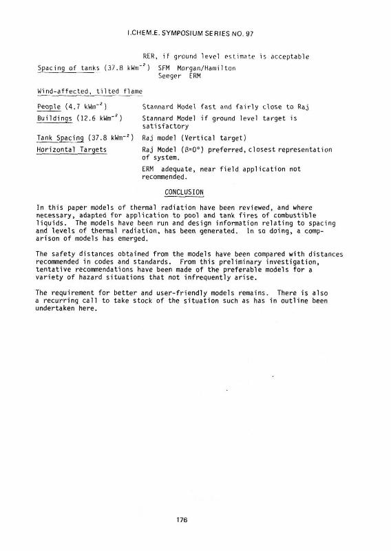
RER, if ground level estimate is acceptable
Spacing of tanks (37.8 kwm~*) SFM Morgan/Hamilton
Seeger ERM
Wind-affected, t i l t e d flame
People (4.7 kWm"2) Stannard Model fast and f a i r l y close to Raj Buildings (12.6 kWm'2) Stannard Model i f ground level target is
sat is factory
Tank Spacing (37.8 kWnr2) Raj model (Vert ical target)
Horizontal Targets Raj Model (8=0°) preferred, closest representation of system. ERM adequate, near field application not recommended.
CONCLUSION
In this paper models of thermal radiation have been reviewed, and where necessary, adapted for application to pool and tank fires of combustible liquids. The models have been run and design information relating to spacing and levels of thermal radiation, has been generated. In so doing, a comparison of models has emerged.
The safety distances obtained from the models have been compared with distances recommended in codes and standards. From this preliminary investigation, tentative recommendations have been made of the preferable models for a variety of hazard situations that not infrequently arise.
The requirement for better and user-friendly models remains. There is also a recurring call to take stock of the situation such as has in outline been undertaken here.
176

I.CHEM.E. SYMPOSIUM SERIES NO. 97
NOMENCLATURE
A v i e w f a c t o r (14) parameter
A, area of flame "seen" by ta rge t (mz)
A' area o f equ i va len t r a d i a t o r "seen" by ground t a r g e t (m*)
A„ re ference h a l f o f equ i va len t r a d i a t o r area (m2)
A, remaining h a l f o f equ i va len t r a d i a t o r area (m2)
A. . v i e w f a c t o r equat ion (27) parameters
8 v i e w f a c t o r equat ion (14) parameter
B Source Rad ius /d is tance from cen te r to t a r g e t
B d i s tance v a r i a b l e f o r "pseudo-pool f i r e " (m)
C (T) s p e c i f i c heat of l i q u i d fue l (kJ kg " )
C s p e c i f i c heat of ambient a i r
C f lame l e n g t h / d i s t a n c e from cen te r t o t a r g e t
D source d iameter (m)
D e q u i v a l e n t d iameter (m)
F v i e w f a c t o r
AH heat of combustion (k-J kg" ) -1
AH heat of vaporisation at the boiling point (kJ kg ) v .1
AH* modified heat of vaporisation (kJ kg )
H tank height (m)
h flame length in wind/pool radius
L mean flame length
L distance from equiv.rad. to target/source radius
L, 'extended' length of pseudo-pool fire (m)
L flame length/source radius -2 -1
m" mass burning rate per unit area (kg m s ) -2-1
m n infinite mass rate per unit area (kg m s )
m mass burning rate (kg s )
N Heskestad Dimensionless Group
N flame length/source radius
Q. total heat release (kW)
q intensity of thermal radiation (kWm~ )
qf flame emissive power (kWm*)
R source radius (m)
r distance from point source to target (m)
r stoichiometric mass ratio of air to volatiles
S distance from source center/radius
S/D tank spacing/diameter
177

I.CHEM.E. SYMPOSIUM SERIES NO. 97
T ambient temperature (K)
T, average flame temperature (K)
T. normal boiling point of fuel (K) -1
U wind velocity (ms )
U characteristic wind velocity (ms" )
U* dimensionless wind velocity
x distance from source center to target (m)
GREEK SYMBOLS
u number of carbon atoms in fuel
6 number of hydrogen atoms in fuel
"Y number of oxygen atoms in fuel
e flame emissivity
* sin"1 (1/S) -1 -2
u0 ambient air viscosity (kg m s )
n radiative output/combustion output
o density of fuel vapour at boiling point (kg m )
p ambient air density (kg m" )
<l> angle between the incident ray and horizontal
T atmospheric transmissivity
o Stefan-Boltzmann Constant 5.67 x 10"11 kW/m2K4
8 deflection of flame from the vertical (flame tilt]
178

I.CHEM.E. SYMPOSIUM SERIES NO. 97
REFERENCES
1. Blinov.V.I. and Khudiakov, G.N. (1957) Academiia Nauks, SSR Ooklady, 1094-1098
2. Hottel, H.C.(1959) Fire Res.Abstr. Rev.l_, 41
3. Burgess, D.S. and Zabetakis.M.G.(1962) U.S. Bureau of Mines, R.I. 6099
4. Babrauskas, V.(1983) Fire Technol. ̂ 9, 251-261
5. Thomas, P.H. (1963) 9th Int'l Symposium on Combustion, 844, Academic Press, N.Y.
6. Thomas, P.H.(1965) F.R. Note 600, Fire Research Station, Borehamwood, England
7. Heskestad, 6.(1983) Fire Safety J. 5, 103-108
8. Welker, J.R., and Sliepcevich.C.M.(1966) Fire Technol, 2, 127
9. Mudan, K.S.(1984) Prog.Energy Combust.Sci. 10. 59-80
10. Hearfield, F., in Lees, F.P. (1980) Loss Prevention in the Process Industries, p.519, Butterworth, London
11. Robertson,R.B. (1976) I.Chem.E.Symp.Series No. 47, 157
12. Atallah.S. and Allan, D.S.(1971) Fire Technol. 7(1), 47-56
13. Parker,R.0.(1974) Fire Technol. K>,147-152
14. Stannard,J.H.(1977) Fire Technol. 13,35-41
15. Hamilton,D.C. and Morgan,W.R.(1952) NACA TN2836, Washington
16. Raj, P.K. and Kalelkar,A.S.(1974) Assessment Models in Support of the Hazard Assessment Handbook (CG-446-3) Chap.9, Technical Report prepared for the U.S. Coast Guard, NTIS publication #AD776617
17. Rein.R.C, Sliepcevich.C.M. and Welker, J.R.(1970) J.Fire.and Flam., 1_, 140
18. Howell, J.R.(1982) A Catalog of Radiation Configuration Factors, McGraw-Hill Book Co. New York
19. Eisenberg.N.A..Lynch,C.J. and Breeding, R.J.,(1975) NTIS AD-A015-245, Springfield,VA
20. Hymes,I.(1983) SRD R275, UKAEA
21. Considine. M,,Grint,G.C.,Holden,P.L,(1982) I.Chem.E, Symp.Ser.No. 7}, 291
22. Seeger,P.G.(1974) Heat Transfer by Radiation from Fires of Liquid Fuels in Tanks, Heat Transfer in Flames, Chap.28, Eds. Afgan.N.H. and Beer,J.M. Scriptor Book Co., Washington, D.C.
179

I.CHEM.E. SYMPOSIUM SERIES NO. 97
23. Wells, G.L.(1980) Safety in Process Plant Design, p.216, George Godwin Ltd., London
24. Lees, F.P.(1980) Loss Prevention in the Process Industries, p. 755, Butterworth, Ondon, U.D.
25. Hughes,J.R.(1970) The Storage and Handling of Petroleum Liquids,p.164 Charles Griffin and Co. Ltd. London
26. Factory Mutual Loss Prevention Data (1970) Storage Tanks for Flammable and Combustible Liquids, F.M. Engineering Corp., 7-88
27. NFPA 30-1981 (1985) Flammable and Combustible Liquids Code, National Fire Protection Association, NFC, v.l
180

I.CHEM.E. SYMPOSIUM SERIES NO. 97
rH t
1 H
t Figure
°s.
i
\ r
Tank \ ^
r 1
1: Tan Mod
c Fire Point Source »1
T L
4-' J,
V Figure 2: Approximate Tank Fire
Equivalent Radiator Model
hH T
i
i i
Pool fire
Ver Tar
-l^k I -
"7~l I I He
L
i. H Tank
Target 3 — I -Target 2
- - I -
Target 1
Figure 3: Pool Fire/Tank Fire Solid Flame Model
Ajc
L Ground Level
J, Target
Flame
H
t>r1 L/2
<
Tank
R
K
Building Target
#
Figure 4: Pool Fire/Tank Fire Equivalent Radiator Model
181

I.CHEM.E. SYMPOSIUM SERIES NO. 97
7 /
2*7 dAj >^c j
Horizontal Target
I
Figure 5: Tank Fire - Horizontal Target System and Viewfactor Geometry
A <L
Figure 6: Tilted Pool Fire/Tank Fire Solid Flame Model
182

I.CH
EM
.E. S
YM
PO
SIU
M S
ER
IES
NO
. 97
183


![Thermal radiation from large pool fires - nvlpubs.nist.gov · ... (SFPE) Handbook entitled, Fire Hazard Calculations for Large Open Hydrocarbon Fires [4]. A summary of various calculation](https://img.pdfslide.us/doc/110x75/5b88986c7f8b9a435b8e1f92/thermal-radiation-from-large-pool-fires-sfpe-handbook-entitled-fire.jpg)