Embed Size (px)
Citation preview
PDHonline Course C447 (5 PDH)
Thermal Processing of Domestic SolidWaste Part 1 of 2 - Combustion Processes
2012
Instructor: Walter R. Niessen, PE, BCEE
PDH Online | PDH Center5272 Meadow Estates Drive
Fairfax, VA 22030-6658Phone & Fax: 703-988-0088
www.PDHonline.orgwww.PDHcenter.com
An Approved Continuing Education Provider
www.PDHcenter.com PDH Course C447 www.PDHonline.org
© Walter R. Niessen 2011 Page 2 of 33
Thermal Processing of Domestic Solid Wastes
Part 1 of 2 - Combustion Processes
Walter R. Niessen, P.E., B.C.E.E.
COURSE CONTENT
This course attempts to answer the question: What is a municipal incinerator? In the early years of refuse
incineration in the United States, incinerators were uncomplicated refractory furnaces equipped with metal grates
(drawn in most respects from existing coal furnace designs) to move the waste into and through the burning
chambers and with (looking back) incredibly simple controls and inefficient air pollution abatement. The furnaces
were designed in a technical collaboration between the public works department of the owner city (county, etc.) their
consulting engineer and the major component vendors (esp. the grate and/or boiler manufacturer). The 1970's saw
the emergence of a new incineration concept: high pressure, waterwall boilers that produced superheated steam that
was fed to turbo-generators for power generation (Waste-to-Energy or WTE plants) and equipped with sophisticated
process control systems and costly, highly efficient air pollution control. This is the technology that dominates the
existing inventory of incineration systems throughout the world.
Such facilities, complex to design and operate, were the product of a new entity: the system vendor. Unlike the
earlier situation, the governmental entity with a waste disposal requirement now found themselves in a commercial
environment where single-point, overall responsibility for the design and, often, the operation of the facility could be
placed in the hands of one of several competing firms. The final working relationship was codified and detailed in a
comprehensive contract document (the Service Agreement). The role of the consulting engineer had largely shifted
to project planning, assistance in financing, permit submissions and the preparation of performance specifications
for competitive bidding by several system vendors. Elsewhere, entrepreneurial system vendors took the lead in
developing a project.
The Service Agreement often goes beyond a simple documentation of a contract to provide waste incineration
services. Since the lifetime of the Agreement is often 15 to 20 years, many of the circumstances defining the nature
of the service, economic factors, environmental requirements and other important parameters will change. Thus, the
Agreement not only defines the baseline set of reference system characterizations that were the basis of the original
procurement but indicates methods and guidelines with which to update the cost and/or performance basis from the
baseline. The characterizations include a AReference Waste@ composition and heat content; unit costs for labor,
utilities, taxes and reagents; environmental requirements; and annual processing rates and energy recovery targets.
The new, system vendor-dominated incineration business employs a wide variety of designs to do the same job. This
individuality reflects both the growth of incineration technology in recent years and the large number of basic design
parameters which are somewhat flexible and can be bent to the prejudices of the design firm. The systems used can
be divided into two broad categories: "mass burn technology" that burns raw, substantially unprocessed refuse and
"refuse derived fuel" (RDF) technology where a prepared, refuse-based fuel is burned. Although mass burn
technology dominates the market in the United States and Europe, both approaches have their strong points and their
advocates.
The course begins with a review of the key characteristics of domestic solid waste followed by the options in mass
burn incinerator components and system designs and the special characteristics of RDF-based combustion systems.
The details of RDF preparation technology is left to other books [1].
www.PDHcenter.com PDH Course C447 www.PDHonline.org
© Walter R. Niessen 2011 Page 3 of 33
A. Introduction
The application of combustion to reduce the volume and sanitize domestic solid waste is an ancient practice
beginning with open burning of wastes near villages or other population centers. Modern application of high
temperature processes in incinerators (now substantially, WTE systems) have been driven by the growth of
population, a community goal of reducing landfilling, increases in per-capita waste generation, the need to increase
the capacity and volume reduction for the substantial invested capital and operating expense over earlier designs,
and regulatory demands to effectively control the residue and air quality impacts of such operations below
acceptable benchmarks of public health impact.
This course assumes a basic understanding of chemistry and mathematics and their application in combustion
systems to the level provided in the two-part PDHonline course: Fundamentals of Combustion. It presumes basic
engineering analysis perspectives but, through text and examples guides the student an understanding of the
processes and interactions of combustion-type domestic waste incineration systems. The course includes:
● The basics characteristics of domestic solid waste;
● The design and operating features of components of waste combustion systems (beyond those of Part 2
of the Fundamentals of Combustion course);
● Mass burn incineration; and
● Refuse derived fuel (RDF) incineration.
Part 2 of the course carries the student further into the emerging class of domestic waste thermal processes:
Conversion systems which process the waste to an intermediate fuel gas which can then be burned or used as a
chemical feedstock.
B. The Characteristics of Domestic Solid Waste
The first step in solving waste management problems is to abandon the hopeless view that Awaste@ is an indefinite
state of matter tied to its genesis as the unusable residue of a process or an unwanted discard of human activity.
Instead, waste should be regarded in its own right as a feedstock, a fuel, and/or a potentially useful material. In this
new light, the analyst then must seek to determine values for the physical and chemical engineering properties that,
though less consistent than those of conventional materials and fossil fuels, nonetheless are the defining measures
that characterize behavior.
One must discard the sense that "waste" is so heterogeneous in its composition and variable in its properties that
problems with its proper management and use cannot be defined, let alone solved. Waste streams will often exhibit
great variability point-to-point and over time. The designer must, therefore, provide processes with more operating
flexibility, reserve capacity and materials "stamina" than conventional process equipment. But the development of
an estimate of average waste composition and properties along with a sense of the expected excursions from those
averages is the necessary starting point of design.
1. Waste Quantities
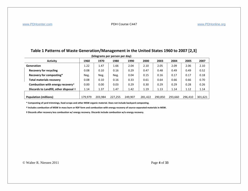
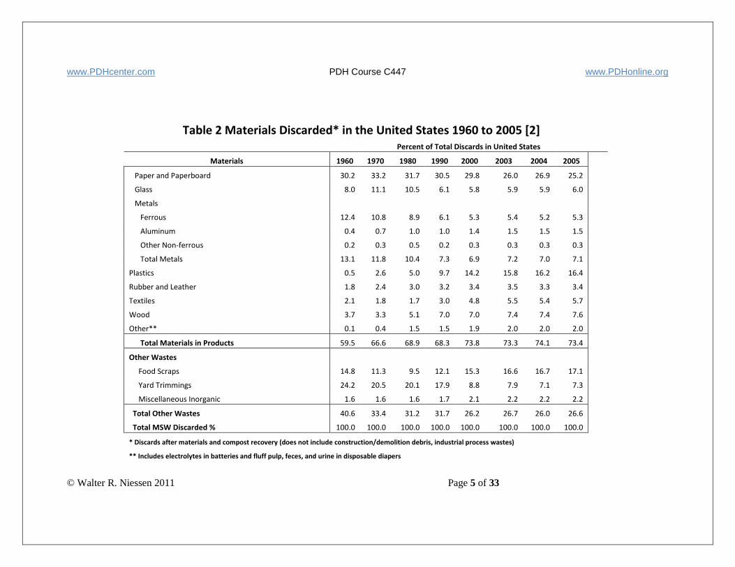
Table 1 presents the pattern of waste generation and disposition in the United States. Table 2 shows year-to-year
averages of waste composition using the EPA method described in Ref. 2. Over this time period the quantity of
waste discarded approximately doubled (from 82 to 166 million tons) reflecting a substantial increase in the quantity
www.PDHcenter.com PDH Course C447 www.PDHonline.org
© Walter R. Niessen 2011 Page 4 of 33
Table 1 Patterns of Waste Generation/Management in the United States 1960 to 2007 [2,3] (kilograms per person per day)
Activity 1960 1970 1980 1990 2000 2003 2004 2005 2007
Generation 1.22 1.47 1.66 2.04 2.10 2.05 2.09 2.06 2.10
Recovery for recycling 0.08 0.10 0.16 0.29 0.47 0.48 0.49 0.49 0.52
Recovery for composting* Neg. Neg. Neg. 0.04 0.15 0.16 0.17 0.17 0.18
Total materials recovery 0.08 0.10 0.16 0.33 0.61 0.64 0.66 0.66 0.70
Combustion with energy recovery† 0.00 0.00 0.03 0.29 0.30 0.29 0.29 0.28 0.26
Discards to Landfill, other disposal ‡ 1.14 1.37 1.47 1.42 1.19 1.13 1.14 1.12 1.14
Population (millions) 179,979
203,984
227,255
249,907
281,422
290,850
293,660
296,410
301,621
* Composting of yard trimmings, food scraps and other MSW organic material. Does not include backyard composting.
† Includes combustion of MSW in mass burn or RDF form and combustion with energy recovery of source-separated materials in MSW.
‡ Discards after recovery less combustion w/ energy recovery. Discards include combustion w/o energy recovery.
www.PDHcenter.com PDH Course C447 www.PDHonline.org
© Walter R. Niessen 2011 Page 5 of 33
Table 2 Materials Discarded* in the United States 1960 to 2005 [2]
Percent of Total Discards in United States
Materials 1960 1970 1980 1990 2000 2003 2004 2005
Paper and Paperboard 30.2 33.2 31.7 30.5 29.8 26.0 26.9 25.2
Glass 8.0 11.1 10.5 6.1 5.8 5.9 5.9 6.0
Metals
Ferrous 12.4 10.8 8.9 6.1 5.3 5.4 5.2 5.3
Aluminum 0.4 0.7 1.0 1.0 1.4 1.5 1.5 1.5
Other Non-ferrous 0.2 0.3 0.5 0.2 0.3 0.3 0.3 0.3
Total Metals 13.1 11.8 10.4 7.3 6.9 7.2 7.0 7.1
Plastics 0.5 2.6 5.0 9.7 14.2 15.8 16.2 16.4
Rubber and Leather 1.8 2.4 3.0 3.2 3.4 3.5 3.3 3.4
Textiles 2.1 1.8 1.7 3.0 4.8 5.5 5.4 5.7
Wood 3.7 3.3 5.1 7.0 7.0 7.4 7.4 7.6
Other** 0.1 0.4 1.5 1.5 1.9 2.0 2.0 2.0
Total Materials in Products 59.5 66.6 68.9 68.3 73.8 73.3 74.1 73.4
Other Wastes
Food Scraps 14.8 11.3 9.5 12.1 15.3 16.6 16.7 17.1
Yard Trimmings 24.2 20.5 20.1 17.9 8.8 7.9 7.1 7.3
Miscellaneous Inorganic 1.6 1.6 1.6 1.7 2.1 2.2 2.2 2.2
Total Other Wastes 40.6 33.4 31.2 31.7 26.2 26.7 26.0 26.6
Total MSW Discarded % 100.0 100.0 100.0 100.0 100.0 100.0 100.0 100.0
* Discards after materials and compost recovery (does not include construction/demolition debris, industrial process wastes)
** Includes electrolytes in batteries and fluff pulp, feces, and urine in disposable diapers
www.PDHcenter.com PDH Course C447 www.PDHonline.org
© Walter R. Niessen 2011 Page 6 of 33
quantity of waste generated and increases in the fraction of the waste diverted from incineration or landfill by
composting and materials recovery. Reference 1 includes a much more detailed description of waste quantities and
distribution among categories including seasonal and geographic factors.
2. Waste Properties
a. General
Desired data are often lacking to precisely define the design basis for waste processing systems. Many waste studies
have demonstrated the large errors possible from desk-top estimates of the generation rate, composition, or
properties of waste. It is strongly recommended, therefore, that especially commissioned waste surveys and
analyses should be incorporated into the problem definition phase of the design effort. Careful consideration should
also be given to the range of variation in composition. For municipal waste, seasonal changes in yard waste content
and local precipitation patterns lead to day-to-day fluctuations in moisture content. Economic class, geographical
region, culinary preferences and residential styles (homes, apartments, hotels and campgrounds) are significant. In
industry, seasonal shifts in production patterns or periodic house-keeping activity lead to variation. Such changes in
waste characteristics must be provided for in the design and operating protocols of waste processing systems. Even
with such relatively obvious foresight, however, the worst (live ammunition, cans of flammable solvent, containers
of toxic chemical, etc.) should be anticipated.
The cardinal rule in waste management design is to ask, "What happens when...?" rather than "What if...?"
Although the analysis of the specific wastes to be processed is desirable, it is useful to have some general data for
preliminary screening of concepts.
b. Composition
Most incinerated material falls within the class "solid waste." Unfortunately, this class of wastes is very difficult to
deal with as an "engineering material". Securing a representative sample is often most problematical. Materials
handling is difficult and can expose workers to risk. Blending is slow and incomplete. However, for incinerator
analysis and design purposes, even highly heterogeneous solid wastes can usefully be considered as a relatively
discrete "material" with acceptably reproducible properties and characteristics. Clearly, a somewhat long averaging
time may be needed before this constancy is apparent. The data and correlations given below are an attempt to
summarize useful information regarding the characteristics of several classes of solid wastes. As with other
information in the waste management engineering field, one must recognize that significant excursions from these
mean values are to be expected.
Composition refers to the category of material (paper, glass, etc.) in the waste streams. Composition data are
reported in this form since the "analysis method," (visual categorization) is low-cost and can rapidly and
economically be applied to large samples of waste. This latter point is important if a meaningful characterization is
to be made on a stream which is grossly heterogeneous. Data in categorical form may be translated into mean
overall chemical compositions and the like by taking the weighted average of the chemical compositions of
specified components. Also, data on a categorical basis are directly usable to estimate the potential for materials
recovery.
In many instances, the waste stream of interest cannot be directly sampled. Under such circumstances, data from
other municipalities can be useful as an indicator of mean refuse composition. Alternatively, the United States EPA
settled on an alternate, non-sampling methodology for waste estimation [2]. The EPA method began with a
comprehensive estimate (based on published data from both the U.S. Department of Commerce and industry
associations) of the domestic production of materials and products including the non-recovered scrap generated in
the course of production. Adjustments were then made for imports/exports and diversions to end-uses outside the
www.PDHcenter.com PDH Course C447 www.PDHonline.org
© Walter R. Niessen 2011 Page 7 of 33
waste stream (e.g., components used for building materials or toilet tissue that is disposed outside conventional solid
waste management systems). Consideration was then given to product lifetime and discounts made for material
recovery (resource recovery and composting). The net remaining comprised the waste flow that was discarded to
energy recovery or landfill.
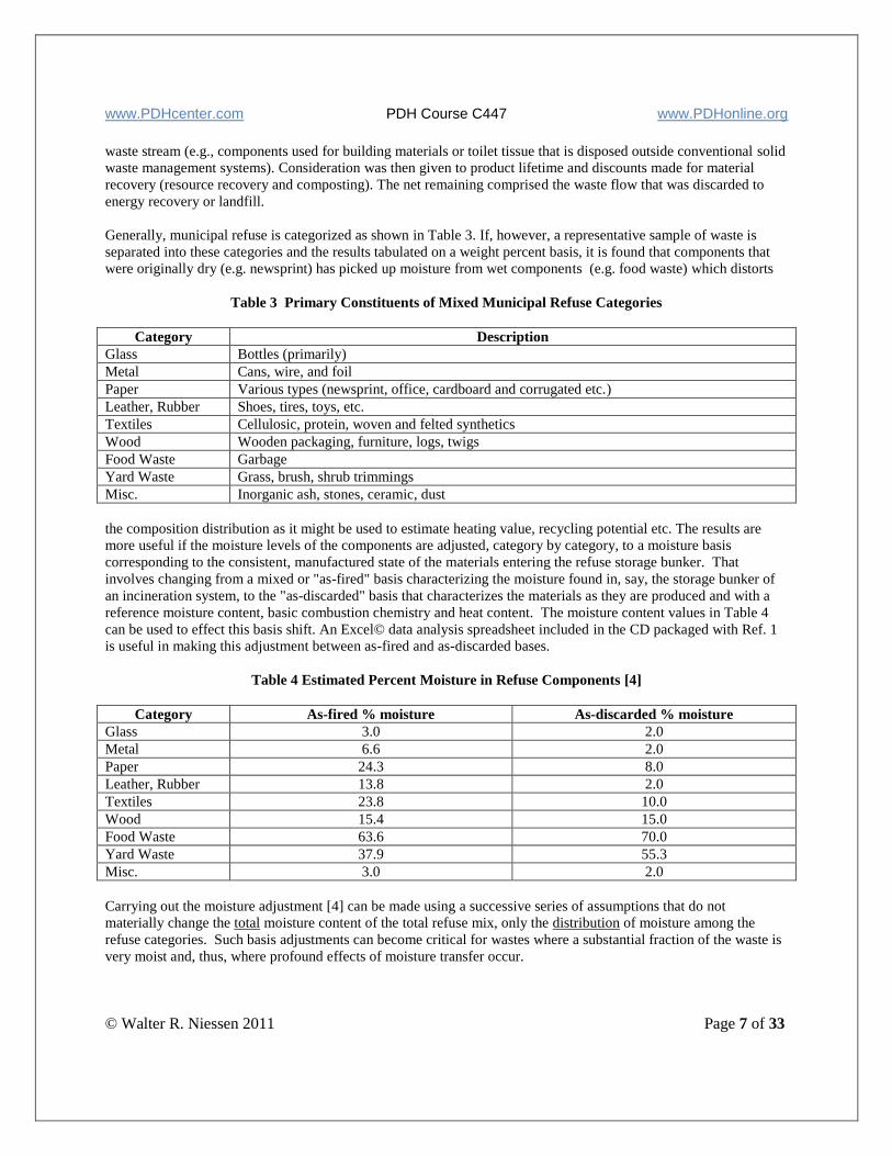
Generally, municipal refuse is categorized as shown in Table 3. If, however, a representative sample of waste is
separated into these categories and the results tabulated on a weight percent basis, it is found that components that
were originally dry (e.g. newsprint) has picked up moisture from wet components (e.g. food waste) which distorts
Table 3 Primary Constituents of Mixed Municipal Refuse Categories
Category Description
Glass Bottles (primarily)
Metal Cans, wire, and foil
Paper Various types (newsprint, office, cardboard and corrugated etc.)
Leather, Rubber Shoes, tires, toys, etc.
Textiles Cellulosic, protein, woven and felted synthetics
Wood Wooden packaging, furniture, logs, twigs
Food Waste Garbage
Yard Waste Grass, brush, shrub trimmings
Misc. Inorganic ash, stones, ceramic, dust
the composition distribution as it might be used to estimate heating value, recycling potential etc. The results are
more useful if the moisture levels of the components are adjusted, category by category, to a moisture basis
corresponding to the consistent, manufactured state of the materials entering the refuse storage bunker. That
involves changing from a mixed or "as-fired" basis characterizing the moisture found in, say, the storage bunker of
an incineration system, to the "as-discarded" basis that characterizes the materials as they are produced and with a
reference moisture content, basic combustion chemistry and heat content. The moisture content values in Table 4
can be used to effect this basis shift. An Excel© data analysis spreadsheet included in the CD packaged with Ref. 1
is useful in making this adjustment between as-fired and as-discarded bases.
Table 4 Estimated Percent Moisture in Refuse Components [4]
Category As-fired % moisture As-discarded % moisture
Glass 3.0 2.0
Metal 6.6 2.0
Paper 24.3 8.0
Leather, Rubber 13.8 2.0
Textiles 23.8 10.0
Wood 15.4 15.0
Food Waste 63.6 70.0
Yard Waste 37.9 55.3
Misc. 3.0 2.0
Carrying out the moisture adjustment [4] can be made using a successive series of assumptions that do not
materially change the total moisture content of the total refuse mix, only the distribution of moisture among the
refuse categories. Such basis adjustments can become critical for wastes where a substantial fraction of the waste is
very moist and, thus, where profound effects of moisture transfer occur.
www.PDHcenter.com PDH Course C447 www.PDHonline.org
© Walter R. Niessen 2011 Page 8 of 33
c. Chemistry
The importance of the chemical composition of a waste is generally greater for sludge/solid wastes than for liquids
and much more so than for gases. This generalization derives from the usually large fraction of non-combustible
inorganic constituents in solid wastes and the frequently important impact of these elements on system design. The
presence of toxic elements and compounds also is important through the resulting impact on worker safety,
combustion system efficiency requirements, and air pollution.
Carbon (C), hydrogen (H) and oxygen (O) are clearly important as the primary elements constituting the fuel
fraction of a waste. From data on CHO alone, most of the contribution to the heating value may be estimated.
Nitrogen is modestly important as it appears in fuel value calculations but can be significant as it affects the
generation of NOx air pollution (via the "fuel nitrogen" mechanism).
Sulfur in the waste as the element, and that appearing in organic sulfur compounds or inorganic sulfides is important
as results in the generation of the acid gases SO2 and SO3 during incineration which impacts on air pollution and
corrosion. Sulfate sulfur (for example, in CaSO4 {gypsum} wallboard) remains in the ash.
Halogen content as organic fluorine or chlorine compounds that generate hydrofluoric or hydrochloric acids (HF,
HCl) as combustion products are important through their air pollution and boiler corrosion consequences. Bromine
and iodine compounds are also significant in these regards but their combustion chemistry and frequency of
appearance differ markedly from the F/Cl case. Note that the high temperature corrosion caused by inorganic
chlorides in the ash layer on boiler tubes has been observed to decrease as the sulfur content of the waste increases.
Phosphorous can be important primarily as it affects the melting point of residues and slag deposits. Burning
organophosphate pesticides produces phosphorous pentoxide (P2O5) that significantly depresses the slag fusion
temperature. Some inorganic phosphates (e.g. FePO4) also depress the ash melting point.
Potassium and sodium content are important as they may indicate the presence of low-melting compounds (e.g.,
NaCl, Na2SO4) which affect slag fusion temperature. The sodium chloride - sulfate eutectic is particularly
troublesome in burning refinery and petrochemical sludge. Also, fused alkali metal compounds often penetrate
porous refractory followed by spalling when the refractory cools.
Toxic organic compounds are clearly important as they impact on worker safety and on the requirement for effective
combustion and combustion control. Stack emission of many specific organic compounds that have demonstrable
health effects at low concentrations (e.g., benzene and vinyl chloride monomer) is limited in many countries by the
air pollution regulations.
Heavy metals and other toxic elements (esp. Cd, Hg, Pb, Zn, Cr, Cu, Be, As, Se, Ni, Ag) are important since
combustion will not destroy them: they will appear in the residue and in the fly ash thus, perhaps, rendering the
residues subject to the hazardous waste regulations with consequent ballooning of the cost, liability and
administrative complexity of residue disposal. Toxic elements with compounds that volatilize at combustion
temperatures (esp. the chlorides and some oxides of Cd, Hg, Pb, Zn, As, Se and Ag) are of interest since they will
often be emitted from the stack as a sub-micron particulate and will deposit on other finely divided particulate.
Most data indicate a significant Aenrichment@ of these elements in the fine particulate matter compared to that in the
total ash in the raw waste.
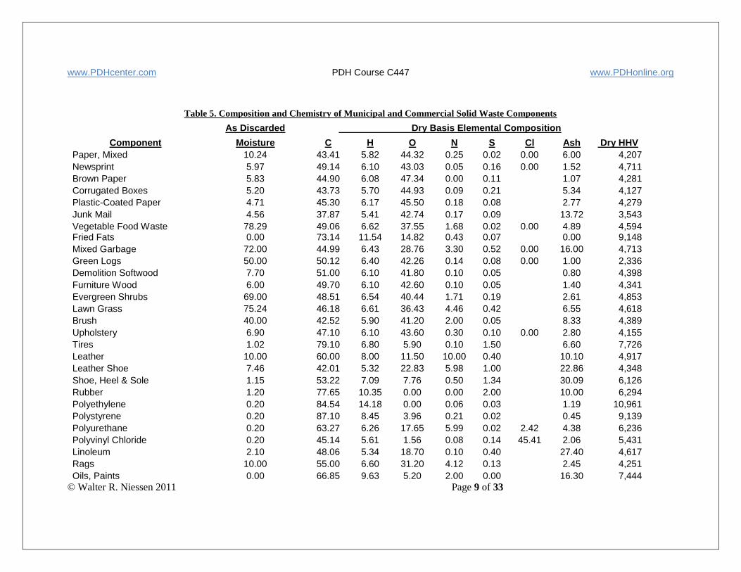
Chemical data for many refuse constituents are shown in Table 5.
www.PDHcenter.com PDH Course C447 www.PDHonline.org
© Walter R. Niessen 2011 Page 9 of 33
Table 5. Composition and Chemistry of Municipal and Commercial Solid Waste Components
As Discarded Dry Basis Elemental Composition
Component Moisture C H O N S Cl Ash Dry HHV Paper, Mixed 10.24 43.41 5.82 44.32 0.25 0.02 0.00 6.00 4,207 Newsprint 5.97 49.14 6.10 43.03 0.05 0.16 0.00 1.52 4,711 Brown Paper 5.83 44.90 6.08 47.34 0.00 0.11
1.07 4,281
Corrugated Boxes 5.20 43.73 5.70 44.93 0.09 0.21
5.34 4,127 Plastic-Coated Paper 4.71 45.30 6.17 45.50 0.18 0.08
2.77 4,279
Junk Mail 4.56 37.87 5.41 42.74 0.17 0.09
13.72 3,543 Vegetable Food Waste 78.29 49.06 6.62 37.55 1.68 0.02 0.00 4.89 4,594 Fried Fats 0.00 73.14 11.54 14.82 0.43 0.07
0.00 9,148
Mixed Garbage 72.00 44.99 6.43 28.76 3.30 0.52 0.00 16.00 4,713 Green Logs 50.00 50.12 6.40 42.26 0.14 0.08 0.00 1.00 2,336 Demolition Softwood 7.70 51.00 6.10 41.80 0.10 0.05
0.80 4,398
Furniture Wood 6.00 49.70 6.10 42.60 0.10 0.05
1.40 4,341 Evergreen Shrubs 69.00 48.51 6.54 40.44 1.71 0.19
2.61 4,853
Lawn Grass 75.24 46.18 6.61 36.43 4.46 0.42
6.55 4,618 Brush 40.00 42.52 5.90 41.20 2.00 0.05
8.33 4,389
Upholstery 6.90 47.10 6.10 43.60 0.30 0.10 0.00 2.80 4,155 Tires 1.02 79.10 6.80 5.90 0.10 1.50
6.60 7,726
Leather 10.00 60.00 8.00 11.50 10.00 0.40
10.10 4,917 Leather Shoe 7.46 42.01 5.32 22.83 5.98 1.00
22.86 4,348
Shoe, Heel & Sole 1.15 53.22 7.09 7.76 0.50 1.34
30.09 6,126 Rubber 1.20 77.65 10.35 0.00 0.00 2.00
10.00 6,294
Polyethylene 0.20 84.54 14.18 0.00 0.06 0.03
1.19 10,961 Polystyrene 0.20 87.10 8.45 3.96 0.21 0.02
0.45 9,139
Polyurethane 0.20 63.27 6.26 17.65 5.99 0.02 2.42 4.38 6,236 Polyvinyl Chloride 0.20 45.14 5.61 1.56 0.08 0.14 45.41 2.06 5,431 Linoleum 2.10 48.06 5.34 18.70 0.10 0.40
27.40 4,617
Rags 10.00 55.00 6.60 31.20 4.12 0.13
2.45 4,251 Oils, Paints 0.00 66.85 9.63 5.20 2.00 0.00
16.30 7,444
www.PDHcenter.com PDH Course C447 www.PDHonline.org
© Walter R. Niessen 2011 Page 10 of 33
d. Heat of Combustion
In the analysis and design of incineration systems, few waste parameters are as important as the heat of combustion.
The correlations and estimation tools supplied in Part 1 of the Combustion Fundamentals course are more tailored to the
waste incineration field and, in some cases, may be more easily applied.
e. Materials Handling
Probably no single element of incineration systems causes more problems than those related to the handling of wastes.
One of the most significant differences between liquid and gaseous waste incineration systems and those for sludge and
solids concern the equipment used to collect, transport, store, reclaim and fire the wastes. In many cases, weaknesses or
failures in the design of materials handling subsystems have greatly reduced the utility and increased the O&M prob-
lems and costs of solid or sludge waste management facilities.
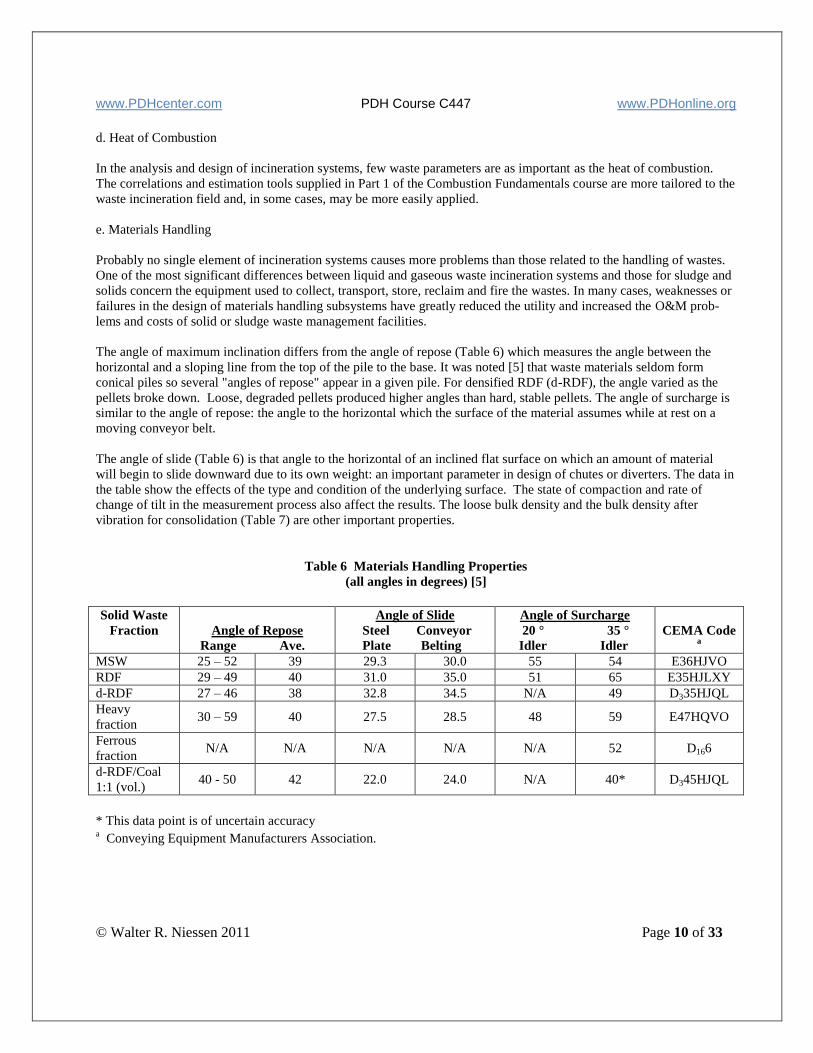
The angle of maximum inclination differs from the angle of repose (Table 6) which measures the angle between the
horizontal and a sloping line from the top of the pile to the base. It was noted [5] that waste materials seldom form
conical piles so several "angles of repose" appear in a given pile. For densified RDF (d-RDF), the angle varied as the
pellets broke down. Loose, degraded pellets produced higher angles than hard, stable pellets. The angle of surcharge is
similar to the angle of repose: the angle to the horizontal which the surface of the material assumes while at rest on a
moving conveyor belt.
The angle of slide (Table 6) is that angle to the horizontal of an inclined flat surface on which an amount of material
will begin to slide downward due to its own weight: an important parameter in design of chutes or diverters. The data in
the table show the effects of the type and condition of the underlying surface. The state of compaction and rate of
change of tilt in the measurement process also affect the results. The loose bulk density and the bulk density after
vibration for consolidation (Table 7) are other important properties.
Table 6 Materials Handling Properties
(all angles in degrees) [5]
Solid Waste
Fraction
Angle of Repose
Range Ave.
Angle of Slide
Steel Conveyor
Plate Belting
Angle of Surcharge
20 ° 35 °
Idler Idler
CEMA Code a
MSW 25 – 52 39 29.3 30.0 55 54 E36HJVO
RDF 29 – 49 40 31.0 35.0 51 65 E35HJLXY
d-RDF 27 – 46 38 32.8 34.5 N/A 49 D335HJQL
Heavy
fraction 30 – 59 40 27.5 28.5 48 59 E47HQVO
Ferrous
fraction N/A N/A N/A N/A N/A 52 D166
d-RDF/Coal
1:1 (vol.) 40 - 50 42 22.0 24.0 N/A 40* D345HJQL
* This data point is of uncertain accuracy a Conveying Equipment Manufacturers Association.

www.PDHcenter.com PDH Course C447 www.PDHonline.org
© Walter R. Niessen 2011 Page 11 of 33
Table 7 Bulk Density (kg/m3) [5]
Solid Waste Fraction Loose
Range Ave.
Maximum
Range Ave.
MSW 61-152 66 66-200 134
RDF 34-50 43 37-72 54
d-RDF 361-387 374 402-486 445
Heavy fraction 366-598 482 334-451 435
Ferrous fraction N/A N/A 194 194
d-RDF/Coal (1:1 (vol.) 712 712 590 590
C. Incineration Systems for Municipal Solid Waste (MSW)
1. Performance Objectives
The performance objectives of a municipal waste incineration system are:
● To process each normal operating day not less than the quantity of waste with an analysis and heat content
equivalent to that specified in the Service Agreement.
● To process the minimum weekly, monthly and/or yearly quantity of waste equivalent to that specified in the
Service Agreement.
● To consistently operate within the emission limits and other legal constraints of all applicable environmental
regulations to include restrictions on the concentrations or mass rates of air or water pollutants, sound
pressure levels, and/or the maintenance of specified system operating parameters within designated limits.
● To protect the health and well-being of incinerator employees and of the commercial and residential community
that abuts the operation.
● To protect the capital investment reflected in the equipment, buildings, roads etc. comprising the incineration
facility such that the useful operating life and maintenance and operating expenses of the incinerator are not
adversely impacted.
● To meet any production guarantees regarding residue quality and quantity; export rates of power, steam or other
energy-related products; or other commercial promises.
The achievement of these objectives is strongly supportive of a healthy plant operation, good customer relations and
good financial performance.
a. Throughput and Refuse Heat Content
Many of these performance objectives are strongly influenced by the characteristics of the waste. The most basic
connection is through the heat content of the waste material since, in essence, an incinerator is a system to process heat.
Therefore, the capacity of an incinerator is intrinsically associated with a maximum heat release rate (the Maximum
Continuous Rating or MCR) and not a mass throughput rate (except as the mass rate, multiplied by the waste heat
content, is equivalent to a heat release rate). Unfortunately, many municipal clients believe that their contract
relationship with the incinerator operator is a commitment to process a given mass of material (e.g., 400 tons per day)
rather than to process a specified number of millions of kilocalories per day. If this potential misperception is not
www.PDHcenter.com PDH Course C447 www.PDHonline.org
© Walter R. Niessen 2011 Page 12 of 33
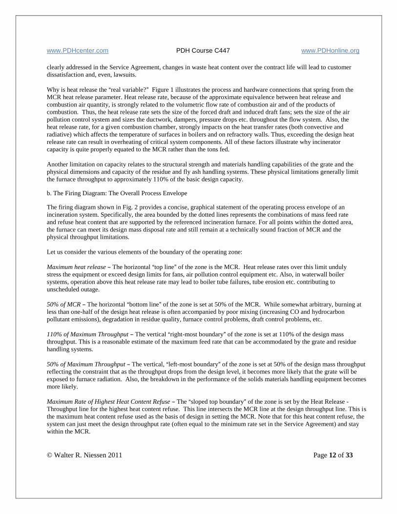
clearly addressed in the Service Agreement, changes in waste heat content over the contract life will lead to customer
dissatisfaction and, even, lawsuits.
Why is heat release the Areal variable?@ Figure 1 illustrates the process and hardware connections that spring from the
MCR heat release parameter. Heat release rate, because of the approximate equivalence between heat release and
combustion air quantity, is strongly related to the volumetric flow rate of combustion air and of the products of
combustion. Thus, the heat release rate sets the size of the forced draft and induced draft fans; sets the size of the air
pollution control system and sizes the ductwork, dampers, pressure drops etc. throughout the flow system. Also, the
heat release rate, for a given combustion chamber, strongly impacts on the heat transfer rates (both convective and
radiative) which affects the temperature of surfaces in boilers and on refractory walls. Thus, exceeding the design heat
release rate can result in overheating of critical system components. All of these factors illustrate why incinerator
capacity is quite properly equated to the MCR rather than the tons fed.
Another limitation on capacity relates to the structural strength and materials handling capabilities of the grate and the
physical dimensions and capacity of the residue and fly ash handling systems. These physical limitations generally limit
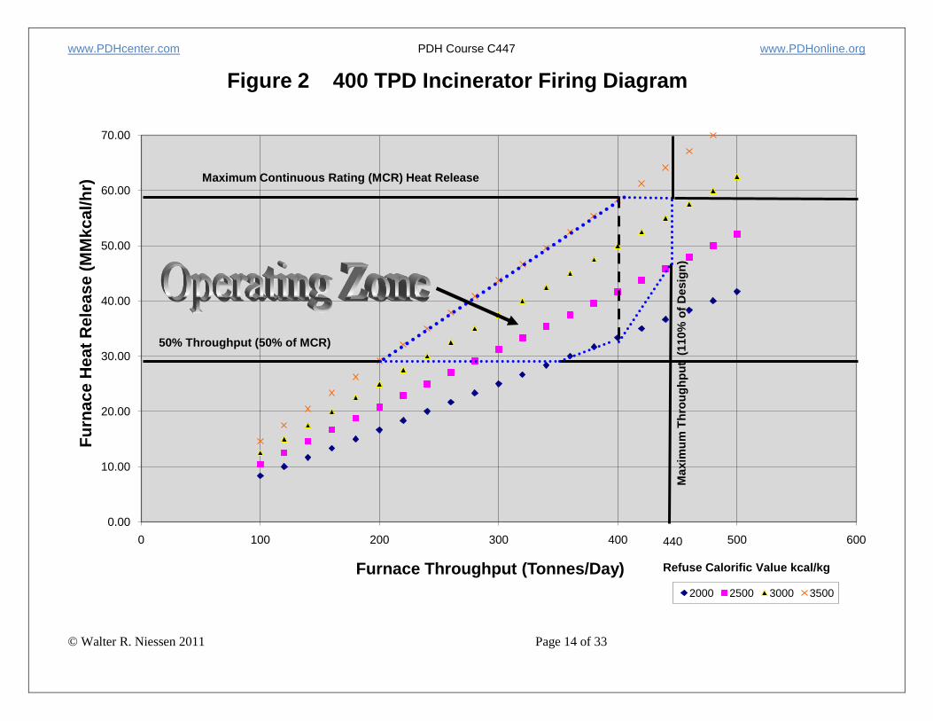
the furnace throughput to approximately 110% of the basic design capacity. b. The Firing Diagram: The Overall Process Envelope The firing diagram shown in Fig. 2 provides a concise, graphical statement of the operating process envelope of an
incineration system. Specifically, the area bounded by the dotted lines represents the combinations of mass feed rate
and refuse heat content that are supported by the referenced incineration furnace. For all points within the dotted area,
the furnace can meet its design mass disposal rate and still remain at a technically sound fraction of MCR and the
physical throughput limitations.
Let us consider the various elements of the boundary of the operating zone:
Maximum heat release B The horizontal Atop line@ of the zone is the MCR. Heat release rates over this limit unduly
stress the equipment or exceed design limits for fans, air pollution control equipment etc. Also, in waterwall boiler
systems, operation above this heat release rate may lead to boiler tube failures, tube erosion etc. contributing to
unscheduled outage.
50% of MCR B The horizontal Abottom line@ of the zone is set at 50% of the MCR. While somewhat arbitrary, burning at
less than one-half of the design heat release is often accompanied by poor mixing (increasing CO and hydrocarbon
pollutant emissions), degradation in residue quality, furnace control problems, draft control problems, etc.
110% of Maximum Throughput B The vertical Aright-most boundary@ of the zone is set at 110% of the design mass
throughput. This is a reasonable estimate of the maximum feed rate that can be accommodated by the grate and residue
handling systems.
50% of Maximum Throughput B The vertical, Aleft-most boundary@ of the zone is set at 50% of the design mass throughput
reflecting the constraint that as the throughput drops from the design level, it becomes more likely that the grate will be
exposed to furnace radiation. Also, the breakdown in the performance of the solids materials handling equipment becomes
more likely.
Maximum Rate of Highest Heat Content Refuse B The Asloped top boundary@ of the zone is set by the Heat Release -
Throughput line for the highest heat content refuse. This line intersects the MCR line at the design throughput line. This is
the maximum heat content refuse used as the basis of design in setting the MCR. Note that for this heat content refuse, the
system can just meet the design throughput rate (often equal to the minimum rate set in the Service Agreement) and stay
within the MCR.

www.PDHcenter.com PDH Course C447 www.PDHonline.org
© Walter R. Niessen 2011 Page 13 of 33
www.PDHcenter.com PDH Course C447 www.PDHonline.org
© Walter R. Niessen 2011 Page 14 of 33
0.00
10.00
20.00
30.00
40.00
50.00
60.00
70.00
0 100 200 300 400 500 600
Fu
rna
ce
He
at
Re
lea
se
(M
Mk
ca
l/h
r)
Furnace Throughput (Tonnes/Day)
Figure 2 400 TPD Incinerator Firing Diagram
2000 2500 3000 3500
Refuse Calorific Value kcal/kg
Maxim
um
Th
rou
gh
pu
t (
110%
of
Desig
n)
440
Maximum Continuous Rating (MCR) Heat Release
50% Throughput (50% of MCR)
www.PDHcenter.com PDH Course C447 www.PDHonline.org
© Walter R. Niessen 2011 Page 15 of 33
Maximum Rate of Lowest Heat Content Refuse B The ASloped bottom boundary@ of the zone is set by the Heat Release -
Throughput line for the lowest heat content refuse that intersects the 50% MCR line and extends to the design capacity
limit.
Since the Operating Zone described in the Firing Diagram is a simple, graphical statement of the maximum operational
capabilities of the incineration system, there are merits to including the Diagram as part of the Service Agreement.
2. Site Design Considerations
The design of the incinerator site impacts significantly on the cost of the facility, the control of storm water run-off,
and the efficiency of the truck traffic flow. Site development costs typically represent two to four percent of the total
cost of a plant, but can increase if substantial earth moving is required for the site. Storm water must be controlled to
limit the impacts of plant runoff on nearby receiving waters (streams, rivers and lakes). Traffic back-ups (queuing) can
occur if the plant roadway system is not configured properly. The designer must consider all of these site issues when
evaluating different sites for the plant, and in orienting the plant on the selected site.
3. Refuse Storage, Handling and Feeding
In the incinerator system, the handling of refuse begins with the delivery of materials to the site. In the United
States most refuse is delivered to the site in motor vehicles. Delivery vehicles can include open dump trucks, com-
mercial vehicles and private cars but most of the waste is conveyed using specialized trucks with equipment for
compression and densification. In some instances, very large (50 to 70-m3) compaction truck trailers are employed
to ferry refuse from centrally located transfer stations.
The refuse loaded into the original collection vehicles usually has a density of about 80 to 240 kg/m3. A power
compaction unit can compress the refuse at the generation site (such as at commercial establishments, hospitals,
apartments, hotels, etc.) to a density of about 500 to 1000 kg/m3. However, most refuse loaded into vehicles at the
collection site is compacted in the truck body to 250 to 500 kg/m3. Most incinerators have a scale to weigh the
incoming refuse.
Refuse is a perverse material with unusual physical and mechanical properties. Unlike many solids, it does not cone
when piled up and often exhibits a negative angle of repose (an overhang). Because of its source and moisture content,
portions of the waste can be sticky so it may not discharge cleanly from belt or apron conveyors. This can cause
housekeeping problems along the return run. Waste compresses, which can result in binding at points of close
tolerance in moving machinery. Since the compressed material is not brittle and thus does not break off, the tough,
compressed waste can keep gates and doors from closing fully. Waste comes in a wide range of physical forms (sheets,
ribbons, bales, cans and bottles, books, powders, boxes and magazines, food scraps and so on). This variability
emphasizes the special need for rugged and flexible materials handling equipment.
a. Tipping Floor-Based Waste Storage and Reclaim Systems
In small incinerator plants (say, less than 150 tons per day), a paved tipping floor is used where the refuse is dumped
directly onto the floor by the collection vehicles and marshaled into piles using front end loaders. On demand, waste
is reclaimed from the storage piles and charged to the incinerator(s). The tip floor area for the storage piles includes
a concrete push-wall so that the pile does not move when a front-end loader picks up a load. Typically, the
maximum pile height is 3.5 to 4 meters and typical waste density is 200 to 250 kg/m3.
The floor-dump approach is low in initial capital cost in comparison to the pit and crane design described below.
Also, the floor dump facilitates visual checking of incoming refuse for excluded wastes (e.g., hazardous materials
and automobile batteries). However, fire control is difficult.
b. Pit and Crane-Based Waste Storage and Reclaim Systems
In larger incinerator plants, refuse is most often received and stored in a pit below ground level. A traveling crane
with an “orange peel grapple” is most often used to pile the refuse for storage and to move it away from the area just
below the unloading area so the pit can accommodate additional refuse. (see course notes: Fundamentals of
www.PDHcenter.com PDH Course C447 www.PDHonline.org
© Walter R. Niessen 2011 Page 16 of 33
Combustion Part 2). The crane and bucket are also used to feed the incinerator furnace. Generally, the pit is sized to
hold the quantity of refuse that can be burned in 2 to 3 days. Open receiving areas are possible but they are infrequently used. The receiving area should be enclosed to avoid
windblown refuse from causing a nuisance, to control dust and odors, and to prevent rain, snow and ice from wetting
the refuse and interfering with the vehicles. Fires in the pit are not uncommon
c. Bin Storage and Reclaim Systems for RDF Systems to store and retrieve RDF are critical to the operational success of all classes of RDF combustion systems.
Because the processed RDF, sitting quiescently in a bin or other storage bunker, has a tendency to Aknit@ together
into a coherent structure, dynamic storage is provided that involves continuous operation of the withdrawal mecha-
nism and continuous recycle of the unfed RDF flow. A second aspect of successful dynamic storage has sometimes
involved the installation of vertical screws in the storage bins to continuously Afluff@ the RDF. Parallel paired
counter-rotating withdrawal screws in the bin bottom provide a Alive bottom@ feature that also has proven successful
but, with continuous movement, the wear problems fostered by the highly abrasive nature of waste, sand and grit is
exacerbated and fouling with wires or ribbons is common. The RDF storage bin is important because, in most instances, the RDF preparation system is only operated on a one-
or two-shift basis. The RDF processing capacity is often considerably greater than the needs of the combustion
facility. Thus, a facility is needed to hold a relatively large working volume of waste to bridge over the shift outages
and maintenance outages of the processing system. Ideally, a surge storage bin is interposed between the long-term
storage bin and the combustor. The quantity of material in the surge bin usually corresponds to 5 to 10 minutes of
firing at the design rate. d. Feeding Systems Hopper feeding using hydraulic rams is conventionally used in small incineration systems (see Solids Feeding in
Part 2 of the Combustion Fundamentals Course. In larger, mass-burn incinerators, the grapple is used to feed a chute
discharging into the primary combustion chamber as shown in Figure 3.
Feeders for refuse derived fuel (RDF) involve either mechanical vaned spreaders or pneumatic spreaders. An
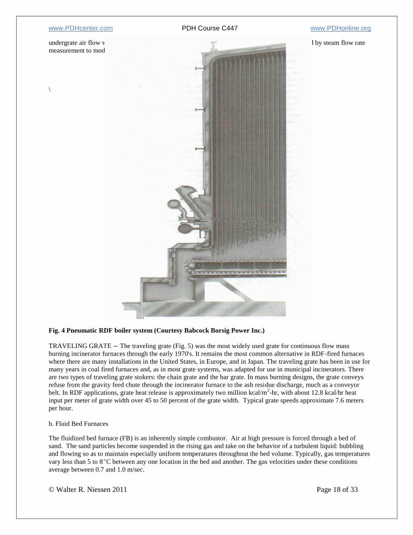
example of the latter is shown in Fig. 4.
4. Grates and Hearths
Small incineration furnaces use a stationary grate or refractory hearth to support the burning refuse. Most of the
larger plants use one of several available grate types to support and transport the refuse while simultaneously stoking
or mixing the refuse during the combustion process. Suspension burning is the only process that does not neces-
sarily require a hearth or grate, since most of the refuse is oxidized while in suspension in furnace gases. However,
a burnout grate is usually installed at the bottom of suspension burning furnaces to achieve more complete burnout
of combustibles in the residue and to provide burnout time for oversize. Experience shows that only when the refuse
has been shredded to 95% < one centimeter can one consider abandoning the burn-out grate. There are many differ-
ent types of hearths or grates, each of which has its own special features.
a. Mechanical Grates: Continuous Operations
Mechanical constant-flow grates have been and are being used in most of the newer continuous burning municipal-
scale incinerators (see Fig. 3). The constant-flow grate draws refuse from the refuse feed chute into the incinerator
furnace, provides movement of the refuse bed and ash residue toward the discharge end of the grate, and does some
stoking and mixing of the burning material on the grates. Underfire air passes upward through the grate to provide
oxygen for the combustion processes, while at the same time cooling the metal portions of the grate to protect them
from oxidation and heat damage. Typical grate designs correspond to an average heat release rate of 13,500 to 16,000
kcal m-2
min-1
. Clearly, the actual rate in different portions of the grate differs widely from this average.
www.PDHcenter.com PDH Course C447 www.PDHonline.org
© Walter R. Niessen 2011 Page 17 of 33
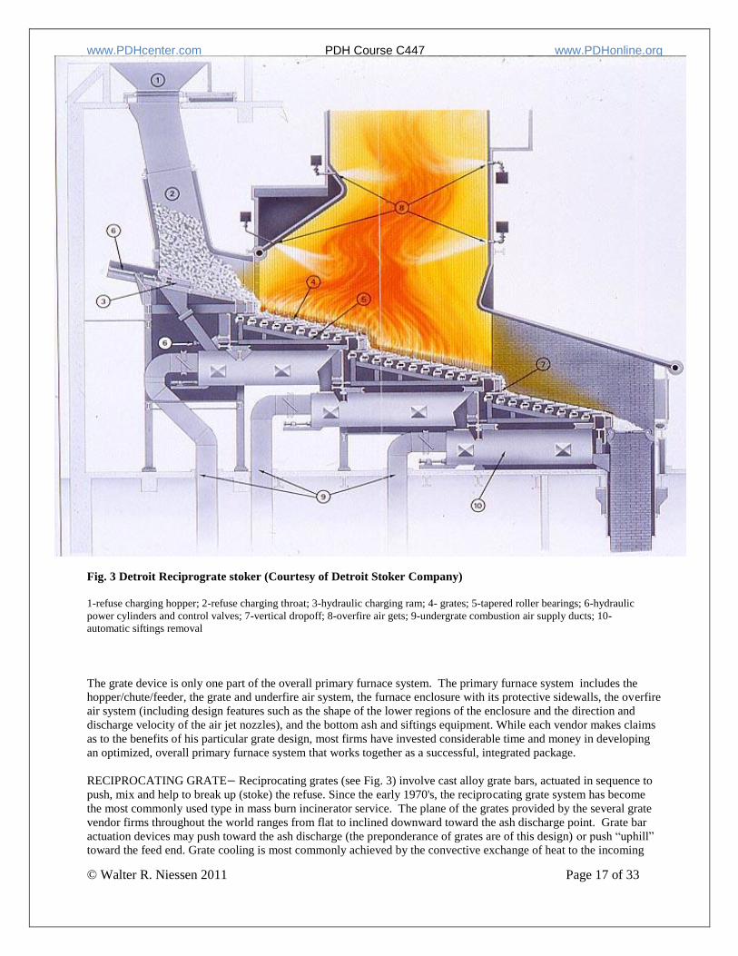
Fig. 3 Detroit Reciprograte stoker (Courtesy of Detroit Stoker Company)
1-refuse charging hopper; 2-refuse charging throat; 3-hydraulic charging ram; 4- grates; 5-tapered roller bearings; 6-hydraulic
power cylinders and control valves; 7-vertical dropoff; 8-overfire air gets; 9-undergrate combustion air supply ducts; 10-
automatic siftings removal
The grate device is only one part of the overall primary furnace system. The primary furnace system includes the
hopper/chute/feeder, the grate and underfire air system, the furnace enclosure with its protective sidewalls, the overfire
air system (including design features such as the shape of the lower regions of the enclosure and the direction and
discharge velocity of the air jet nozzles), and the bottom ash and siftings equipment. While each vendor makes claims
as to the benefits of his particular grate design, most firms have invested considerable time and money in developing
an optimized, overall primary furnace system that works together as a successful, integrated package.
RECIPROCATING GRATE− Reciprocating grates (see Fig. 3) involve cast alloy grate bars, actuated in sequence to
push, mix and help to break up (stoke) the refuse. Since the early 1970's, the reciprocating grate system has become
the most commonly used type in mass burn incinerator service. The plane of the grates provided by the several grate
vendor firms throughout the world ranges from flat to inclined downward toward the ash discharge point. Grate bar
actuation devices may push toward the ash discharge (the preponderance of grates are of this design) or push “uphill”
toward the feed end. Grate cooling is most commonly achieved by the convective exchange of heat to the incoming
www.PDHcenter.com PDH Course C447 www.PDHonline.org
© Walter R. Niessen 2011 Page 18 of 33
undergrate air flow which is adequate to protect the grate from burn-out. Grate speed is controlled by steam flow rate
measurement to modulate heat release while achieving acceptable burn-out.
\
Fig. 4 Pneumatic RDF boiler system (Courtesy Babcock Borsig Power Inc.)
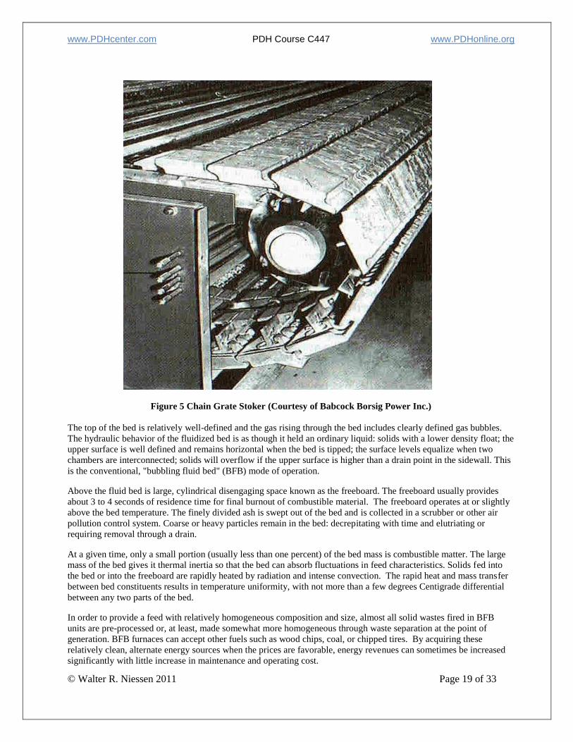
TRAVELING GRATE − The traveling grate (Fig. 5) was the most widely used grate for continuous flow mass
burning incinerator furnaces through the early 1970's. It remains the most common alternative in RDF-fired furnaces
where there are many installations in the United States, in Europe, and in Japan. The traveling grate has been in use for
many years in coal fired furnaces and, as in most grate systems, was adapted for use in municipal incinerators. There
are two types of traveling grate stokers: the chain grate and the bar grate. In mass burning designs, the grate conveys
refuse from the gravity feed chute through the incinerator furnace to the ash residue discharge, much as a conveyor
belt. In RDF applications, grate heat release is approximately two million kcal/m2-hr, with about 12.8 kcal/hr heat
input per meter of grate width over 45 to 50 percent of the grate width. Typical grate speeds approximate 7.6 meters
per hour.
b. Fluid Bed Furnaces
The fluidized bed furnace (FB) is an inherently simple combustor. Air at high pressure is forced through a bed of
sand. The sand particles become suspended in the rising gas and take on the behavior of a turbulent liquid: bubbling
and flowing so as to maintain especially uniform temperatures throughout the bed volume. Typically, gas temperatures
vary less than 5 to 8C between any one location in the bed and another. The gas velocities under these conditions
average between 0.7 and 1.0 m/sec.
www.PDHcenter.com PDH Course C447 www.PDHonline.org
© Walter R. Niessen 2011 Page 19 of 33
Figure 5 Chain Grate Stoker (Courtesy of Babcock Borsig Power Inc.)
The top of the bed is relatively well-defined and the gas rising through the bed includes clearly defined gas bubbles.
The hydraulic behavior of the fluidized bed is as though it held an ordinary liquid: solids with a lower density float; the
upper surface is well defined and remains horizontal when the bed is tipped; the surface levels equalize when two
chambers are interconnected; solids will overflow if the upper surface is higher than a drain point in the sidewall. This
is the conventional, "bubbling fluid bed" (BFB) mode of operation.
Above the fluid bed is large, cylindrical disengaging space known as the freeboard. The freeboard usually provides
about 3 to 4 seconds of residence time for final burnout of combustible material. The freeboard operates at or slightly
above the bed temperature. The finely divided ash is swept out of the bed and is collected in a scrubber or other air
pollution control system. Coarse or heavy particles remain in the bed: decrepitating with time and elutriating or
requiring removal through a drain.
At a given time, only a small portion (usually less than one percent) of the bed mass is combustible matter. The large
mass of the bed gives it thermal inertia so that the bed can absorb fluctuations in feed characteristics. Solids fed into
the bed or into the freeboard are rapidly heated by radiation and intense convection. The rapid heat and mass transfer
between bed constituents results in temperature uniformity, with not more than a few degrees Centigrade differential
between any two parts of the bed.
In order to provide a feed with relatively homogeneous composition and size, almost all solid wastes fired in BFB
units are pre-processed or, at least, made somewhat more homogeneous through waste separation at the point of
generation. BFB furnaces can accept other fuels such as wood chips, coal, or chipped tires. By acquiring these
relatively clean, alternate energy sources when the prices are favorable, energy revenues can sometimes be increased
significantly with little increase in maintenance and operating cost.
www.PDHcenter.com PDH Course C447 www.PDHonline.org
© Walter R. Niessen 2011 Page 20 of 33
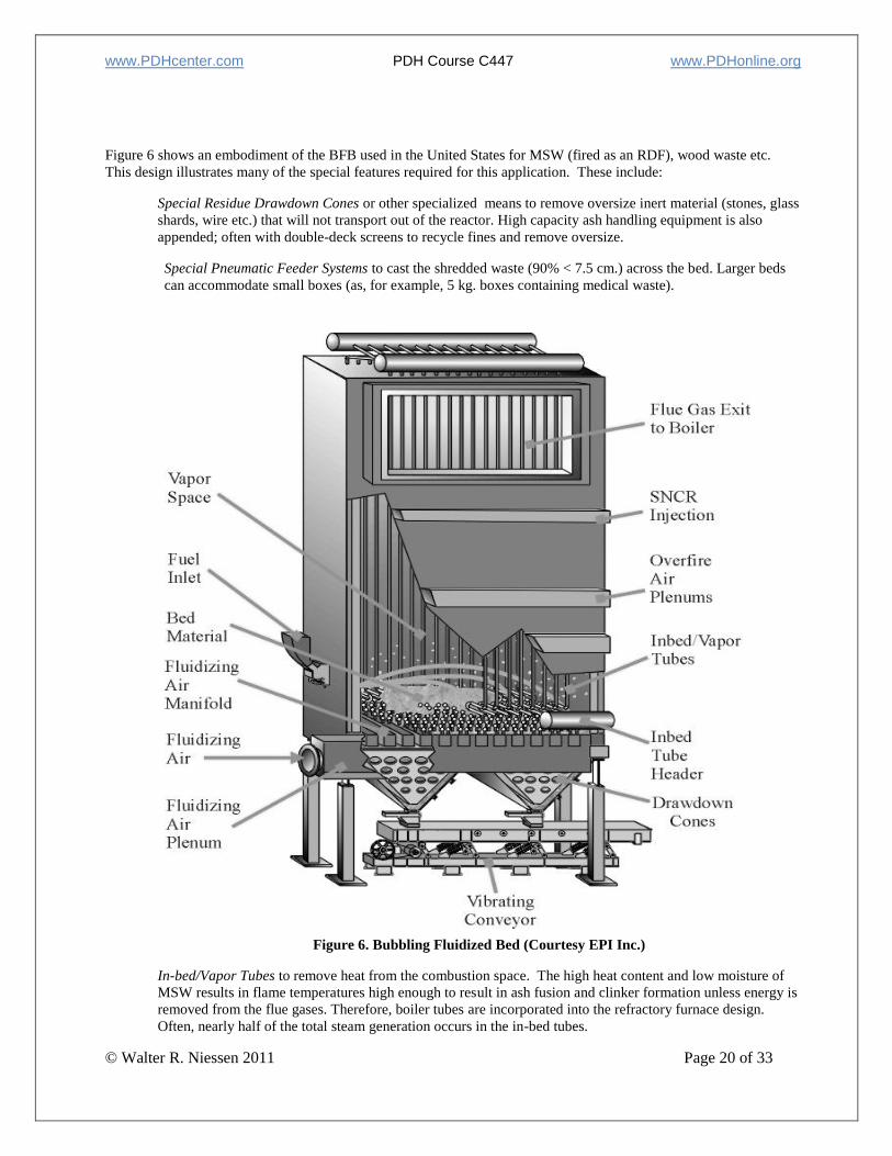
Figure 6 shows an embodiment of the BFB used in the United States for MSW (fired as an RDF), wood waste etc.
This design illustrates many of the special features required for this application. These include:
Special Residue Drawdown Cones or other specialized means to remove oversize inert material (stones, glass
shards, wire etc.) that will not transport out of the reactor. High capacity ash handling equipment is also
appended; often with double-deck screens to recycle fines and remove oversize.
Special Pneumatic Feeder Systems to cast the shredded waste (90% < 7.5 cm.) across the bed. Larger beds
can accommodate small boxes (as, for example, 5 kg. boxes containing medical waste).
Figure 6. Bubbling Fluidized Bed (Courtesy EPI Inc.)
Figure 6. Bubbling Fluidized Bed (Courtesy EPI Inc.)
In-bed/Vapor Tubes to remove heat from the combustion space. The high heat content and low moisture of
MSW results in flame temperatures high enough to result in ash fusion and clinker formation unless energy is
removed from the flue gases. Therefore, boiler tubes are incorporated into the refractory furnace design.
Often, nearly half of the total steam generation occurs in the in-bed tubes.
www.PDHcenter.com PDH Course C447 www.PDHonline.org
© Walter R. Niessen 2011 Page 21 of 33
Selective Non-Catalytic Reduction (SNCR) injection of reagent (such as ammonia or urea solution) to reduce
NOx by reduction to elemental nitrogen.
Overfire Air Injection to enhance mixing and complete the supply of combustion air (typically about 40-50%
excess air overall) to assure complete burn-out of char, CO, VOC’s and other combustible gases/pollutants.
Overall residence time is about 4 seconds; 2.5 seconds after overfire air injection.
5. Enclosures
The furnace enclosure provides a controlled environment for the combustion process in the incinerator system.
Without the furnace enclosure, the combustion process would be, in effect, "open burning." Incinerator enclosures
(refractories, boiler systems etc.) were discussed in the Combustion Fundamentals (Part 2) course.
Combustion engineers know that a hot, well-mixed system, supplied with sufficient air will achieve complete burnout
of even the most refractory organic compounds in only a fraction of a second. For conventional fuels, burner designs
can be honed with the combined guidance of experiment and theory (the latter greatly aided by the regularity of the
system) to coax out superior combustion performance over wide ranges of operating conditions. The features of the
combustion enclosure in this instance are, therefore, more driven by issues of cost, heat transfer optimization and
"packaging convenience" than by the combustion process.
In contrast, we know that grate burning is an inherently poor starting point for the realization of complete combustion.
The air supply is spatially and temporally irregular as is the air demand. The gasification and heat release processes are
in a state of continual upset as the reciprocating grate bars expose new surface and as piles of refuse collapse and fall.
This chaos is in stark contrast to the humming regularity of oil, gas and even pulverized coal flames.
In the incinerator, the physical shape of the furnace enclosure and its appurtenances play a key role in achieving
incineration objectives. The function of the furnace envelope in refuse fired combustors can be critical; guiding cold,
gases from the discharge grate area back to the hotter regions where, after mixing, combustion is initiated; guiding hot
gases to energy depleted zones for ignition and drying; guiding oxygen rich gases to the air-starved pyrolysis zone in
the second third of the grate.
The furnace shape also serves to funnel and accelerate the fuel-rich gases rising from the gasification regions along the
grate to target zones for overfire air jet mixing (see Fig. 3). The walls constrain the flow to maintain gas velocities high
enough to overcome buoyancy-driven stratification and to avoid cold spots and dead zones: wasted combustion
volume. Also, the furnace shape, facilitated by skillful placement of (hot) refractory can provide re-radiation to the
bed: supplying heat energy for the evaporation of moisture.
The achievement of a very high degree of combustible pollutant control in municipal incineration systems over the
period 1975 to 1985 (including reliable destruction of the precursors of dioxin and furan compounds) was a remark-
able technical achievement of the industry. Intensive studies of furnace shape, overfire air injection design, and
combustion controls (coupling combustion environment sensors to refuse feed rates and air supply) combined to
accept and meet the challenge of dealing with grate-fired systems burning unprocessed, non-homogeneous waste.
The volumetric heat release rate characterizes the combustion intensity and wall temperature level in the furnace
enclosure. Although designs vary, most refractory furnaces fall within the range from 130,000 to 225,000 kcal hr-1
m-
3, with an average of about 180,000 kcal hr
-1 m
-3.
In most modern incineration systems, energy recovery in a water-walled boiler generating superheated steam (Waste-
to-Energy or WTE) is the only economically viable and environmentally sound concept for combustion-based waste
processing. With such a concept, the cooling effect of the water-cooled walls allow the excess air to stay low (lowering
the flue gas volume and the size and cost for air pollution control, fans and stacks) and the power revenue provides a
significant off-set to the high capital investment and operating expense of incineration systems. Typical heat release
rates per meter of furnace width in waterwall boiler systems approximate 10 million kcal hr-1
m-1
. The primary
furnace volumetric heat release rate approximates 90,000 kcal hr-1
m-3
Energy markets (a beneficial and lucrative application for the recovered heat) are important to justify incorporating
energy recovery into an incinerator design. Energy markets may be characterized in four ways.
www.PDHcenter.com PDH Course C447 www.PDHonline.org
© Walter R. Niessen 2011 Page 22 of 33
● The size of the market – very large markets are desirable to assure absorption of 100 percent of the energy
recovered. For this reason, sale of electricity into the (essentially bottomless) grid is very attractive;
● The energy type – steam markets are preferred over electricity (to eliminate the capital and operating cost
for steam-to-electricity conversion, switchgear etc.);
● The long-term market reliability with which energy can be sold (risks of market stability over the lifetime
of the financing); and
● The short-term reliability of revenues (the risk of reduced steam use arising from seasonality effects on
space-heating load or process changes).
6. Ash Removal and Handling
Municipal solid waste includes inert materials that cannot be destroyed in the combustion process. Also, the
incineration process is inherently imperfect so that some potentially combustible material is dried, heated and
carbonized but the desired next step (gasification of the char) is not achieved. Further, some material simply Afalls
between the cracks@ of grates (siftings) and leaves the hot combustion environment substantially unburned. These three
components comprise bottom ash, the inevitable residue of municipal solid waste incineration operations. Municipal
incinerator ash is usually characterized as:
Bottom ash: the ash that falls from the grate combined with the siftings that fall through the grate; or
Fly ash: the fine ash that becomes airborne in the primary chamber and either settles in the ducts and devices
of the incinerator or, ultimately, becomes the inlet loading of particulate matter to the air pollution control
system. The fly ash includes refuse constituents that volatilize in the high temperature zones of the furnace
and, subsequently, condense on particulate and reagents (e.g. lime) added for acid gas absorption. Fly ash
may include heavy metals and high molecular weight hydrocarbons with a significant health effect.
The presence of ash imposes several technical and economic stresses on the incineration operation and the incineration
business:
● Since ash is a solid and cannot simply be drained from the incineration system, costly and high
maintenance devices are needed to remove the solids from the combustor and to handle the ash stream.
● Ash (especially the smaller particles in the fly ash) is a concentrate of toxic elements such as lead, nickel
and mercury as well as elements that are both carcinogenic and toxic such as cadmium, hexavalent chromium,
and arsenic.
● Ash constitutes a waste stream of the incinerator and a place must be found to get rid of it. This generates
an operating cost for both transport to its disposal site and for the disposal itself. Potentially, landfill disposal
leaves the incinerator firm with a liability for groundwater contamination and other adverse short and long
term consequences of residue disposal.
● Ash hazards (real or imagined) have emerged in many countries as a significant concern among the public
and the regulatory agencies. These concerns can be addressed but they can be an impediment to project
implementation.
● Ash (especially bottom ash) is variable in its properties including both large clinkers and fine dusts, it may
include both massive and wire metals and ceramic and stony materials, and it exhibits a variety of colors,
mechanical strengths and other physical and chemical properties. Other than by the extraction of ferrous
metal (easy to accomplish with a simple magnetic separator), processing the residue to adjust its properties to
meet the demands of the marketplace can be quite costly in comparison to the modest revenue stream that can
be expected.
www.PDHcenter.com PDH Course C447 www.PDHonline.org
© Walter R. Niessen 2011 Page 23 of 33
All of these factors can be important in making the environmental assessments, developing the operating strategy and
carrying out the economic analysis concerned with municipal solid waste incineration.
a. Bottom Ash
After complete incineration of the refuse, the ash residue drops into an ash chamber or chute from the end of the grate
or kiln. In some instances, a roller is located at the discharge point on the grate to allow the operator to hold back the
residue to allow material to burn further or when there is a problem with the ash discharger or ash handling conveyors.
Siftings that have fallen through the grates (which may have been either partially or completely burned) and collected
fly ash also may be conveyed to this ash chamber. The ash may be discharged directly into a container or onto suitable
conveyors for disposal, or into water for quenching and cooling. The ash residue is then removed from the water with
a hydraulic ram, drag conveyor, pusher conveyor, or other means.
To prevent in-leakage of air (disrupting the combustion air balance in the furnace) or out-leakage of furnace gases at
the point where the gas is removed (impacting on air quality in the working environment), a positive air seal is
necessary. Dry mechanical seals and seals made by covering the ash receptacle or container have been used to control
air leakage. With wet removal of the ash, a wet or hydraulic (water) seal is used or a combination of a wet and
mechanical seal is used. In order to keep this critical subsystem of the incinerator functioning, designs must
incorporate features of ruggedness, flexibility and resilience. Weak, undersized ash handling systems will cause
shutdowns.
1) Wet Systems
In most plants in the United States, Europe and Japan, the ash is quenched in a water trough at the discharge end of the
grate. Most plants use a discharge plunger ram to push the quenched ash up an inclined ramp (to drain superficial
water) discharging to an apron or vibrating conveyor. Older U.S. incinerator designs and small modular units quench
grate residue in a trough filled with water (to provide an air seal) with a drag-chain conveyor running in the trough to
pull out the quenched residue.
2) Dry Systems
If a dry system is to be used, means are required to assure that (1) ash is dumped frequently (avoiding excessive build-
up) and (2) door opening actions are properly sequenced so that only one door to the combustion chamber is open at
any one time.
b. Siftings
Siftings are the fine material that drops through openings in the grate into the air plenums. Screw conveyors or other
appropriate materials handling systems are used to move the siftings to the bottom ash discharge point.
c. Fly Ash
Dry fly ash handling is usually provided using an enclosed screw conveyor. These conveyors are low in cost and
efficient to handle the fine dusts collected in electrostatic precipitators and bag houses. In the simplest configuration,
the fly ash is simply combined with the bottom ash. However, environmental regulatory agencies may require
separate disposal of bottom ash and fly ash.
d. Materials Recovery from Ash
In a few plants, the bottom ash is processed for ferrous metal recovery. In a few instances, additional processing of the
residue yields materials useful as a fill or for road construction.
1) Ferrous Metal Recovery
In the United States, Japan and Europe the quantity of ferrous metal in incinerator residue ranges from 6 to 9 percent
by weight. The technology of ferrous metal recovery is simple, the capital and operating cost is low and the installation

www.PDHcenter.com PDH Course C447 www.PDHonline.org
© Walter R. Niessen 2011 Page 24 of 33
has little impact on plant layout or staffing requirements. Ferrous recovery is generally effected by use of a belt
electromagnet. Most often, the magnetic belt is located at a transfer point for the residue conveyor and the recovered
ferrous is cast into a chute to a second receiving container.
2) Roadbeds and Earthworks
Following processing for ferrous metal removal, the medium ash solids, such as clinker particles, portions of fused
glass, or particles of shattered glass that pass the magnet can sometimes be screened for use as fill material or for use
in surfacing and construction of alleys and secondary streets [1].
7. Pollution Control
An incinerator is probably of greatest concern to a municipality because of the fear of the air pollution impact on the
contiguous environment. The “emission factors” characterizing the relationship between waste properties, design and
operating parameters and the uncontrolled emission rates and the effectiveness of options in abatement technology are
major technical areas and are dealt with in comprehensive incineration texts [1] and in other courses.
Water pollution from the process drains and blow down and from residue disposal is a secondary issue in comparison
to air emissions but still merits careful consideration and control. Also, an incinerator can create undesirable noise and
cause the surrounding area to be unattractive because of vehicle traffic, collection truck litter and other forms of trash
which quickly disfigure an incinerator site where good housekeeping is not regarded as a fundamental plant responsi-
bility.
a. Air Pollution
The most noticeable forms of air pollution are fly ash, smoke, odors (from the stack as well as other areas), noxious
gases, and dust. Honesty would require acknowledgement that all of these will emanate from an incinerator at times.
However, the net impact (health and aesthetic) of these emissions, as mitigated by the normal buffering area around
the plants and high levels of control, is negligible.
1) Composition of the Flue Gases
If combustion of the volatile fraction of the refuse is complete, the composition of the flue gas will be principally
nitrogen, oxygen, water vapor and carbon dioxide. There will also be small amounts of sulfur oxides, nitrogen oxides
and mineral acids (principally hydrochloric acid, which will result from the combustion of halogenated plastics,
particularly polyvinyl chloride). Normally, the concentration of sulfur oxides, nitrogen oxides, and mineral acids will
be high enough so that they will trigger the regulatory requirement for air pollution control. If combustion of the
volatile is not complete, the flue gases will contain carbon monoxide and other unburned or partly burned organic
materials (“volatile organic compounds or VOCs). These emissions are more subtle but can include the poly-
chlorinated dibenzo p-dioxin and dibenzo furan compounds, POMs and the like. The first easily visible indication of
the presence of these materials in high concentrations will be the appearance of black smoke from the incinerator
stack, which may be followed by the detection of objectionable odors.
The presence of unburned or partially burned materials is unnecessary and is caused by the poor operation of the
incinerator. Their emissions can and are controlled by the proper operation of the incinerator rather than the installa-
tion of control devices. Complete combustion can be assured by operating the incinerator (after the last point of air
injection) at high temperatures (from 750 to 1000C); by providing sufficient air for combustion; by providing
sufficient residence time for the combustion process to occur; and by inducing (by both gas passage configuration and
well designed overfire air jets) sufficient turbulence in the combustion space to mix the combustible gases and aerosols
with the necessary air. Modern units achieve these goals using sophisticated monitoring and control of the combustion
environment. Also, catalysts can be incorporated into fabric filters to enhance dioxin destruction.
Such residence time and some mixing are usually provided for by ducting the flue gases to a secondary combustion
chamber or zone. Although it is not essential that a discrete second chamber be provided, it is necessary to provide
sufficient volume in the furnace, preceded by vigorous induced mixing at elevated temperature to assure that the com-
bustion process is completed. Few single-chamber incinerators meet this requirement.
www.PDHcenter.com PDH Course C447 www.PDHonline.org
© Walter R. Niessen 2011 Page 25 of 33
2) Control of Particulate Matter and Acid Gases
Particulate matter (characterized by flue gas weight loading), generally referred to as fly ash, is generated in and
elutriated by the combustion process and must be removed from the effluent gases. The amount of particulate matter
which is generated is somewhat dependent upon the design and operation of the incinerator. If the combustion process
is not complete, a sooty fly ash will result.
Studies indicate that there is a correlation between the amount of fly ash entrained in the effluent gases and the dis-
tribution and amount of overfire and underfire air and the type of grate employed. No matter how carefully the
incinerator is operated, however, particulate matter will be entrained in the effluent gases. In a properly designed and
operated incinerator, equipped with appropriate air pollution control equipment, all of the stringent standards
established by states and the federal government can be met.
Although the flue gases from incinerators contain a number of pollutants, air pollution control equipment installed on
these units is primarily directed at the problem of particulate removal. For this purpose, a number of devices are in
use, ranging in particulate removal efficiency up to above 99%. In light of present and forecast particulate emission
standards throughout the world, control efficiencies in excess of 98% are generally required and routinely achieved.
Electrostatic precipitators (ESP) and fabric filters are commonly used for particulate removal from incinerator flue
gases. Both systems can be used in conjunction with a spray dryer absorber where fine droplets of a slurry of lime are
injected at temperatures where total evaporation results yielding highly reactive alkaline particles that absorb both SO2
and HCl. The fabric filter is preferred since it has a higher fine-particle control efficiency (important in metal control)
and it offers the advantage that the captured filter cake gives a second contact opportunity for acid gas control in
comparison with an ESP when used with a spray dryer absorber. Also, as noted below, it has been observed that the
normal working temperatures of ESPs are ideal for the formation of dioxin compounds, an undesirable byproduct
characteristic.
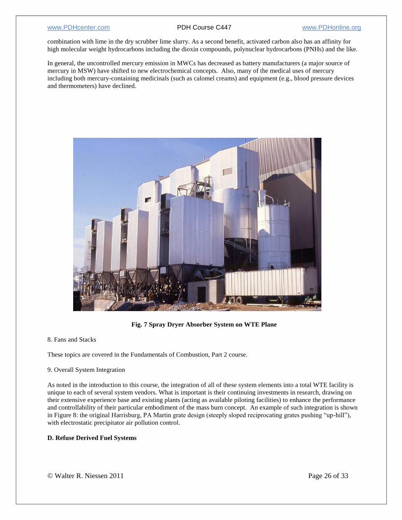
A WTE plant with three spray dryer absorber systems installed is shown in Figure 7. On the right is the lime silo. Just
to the left of the silo are the cylindrical absorber evaporation chambers. To their right are the three fabric filters.
3) Control of Trace Pollutants
“Dioxin,” the popular name given to the mixture of polychlorinated dibenzyl-p-dioxins (PCDD) and furans (PCDF)
compounds formed in municipal incinerators and mercury and its compounds have had a profound impact on the
design, operations and public acceptability of WTE facilities. Bench-scale experiments have provided convincing
evidence that PCDD/PCDF compounds are created downstream of the furnace: a catalytically assisted reaction on the
surface of carbonaceous fly ash. Maximum tetra- to octa-PCDD and PCDF formation occurs near 300C. PCDF also
shows a lower peak generation rate near 450C. As the temperature falls below 250C, the reaction rate falls quickly
to near zero. The precursor materials involved are simple: carbon char and inorganic chlorides. Most researchers do
not show a correlation of CDD/CDF generation with the HCl concentration in the flue gases and there has been no
conclusive scientific evidence that specific solid waste components (such as PVC) are responsible for any significant
fraction of the total CDD/CDF. Control of this pollutant has been effective: achieving good combustion of char in the
hot zones of the furnace (“Good Engineering Practice” combustion) and the use of dry scrubber technology for acid
gas control that quickly cools the flue gases below the dioxin formation zones. Also, dioxin reduction is achieved
when activated carbon is injected into the flue gas stream (ostensibly for mercury control), by using fabric filters
incorporating catalysts that degrade dioxins and with catalytic dioxin destruction means downstream of the fabric
filter. These technology options are discussed in other resources [1].
A second pollutant of concern relates to the concentration and emission chemistry of mercury and its compounds.
Almost all of the mercury in the feed waste appears in the furnace gases (rather than the bottom ash) because of the
high volatility of elemental mercury (boiling point 357C) and the fact that all of its compounds decompose at
relatively low temperatures. The chemistry of mercury in the flue gases has an effect on the accuracy of mercury
emission data: elemental mercury (Hg or Hg2), mercuric or mercurous chloride (HgCl2 or HgCl) mercuric or
mercurous sulfide (HgS or Hg2S) etc. The chemistry-related effects result from the impact of physical form (gas or
solid) and/or reactions in the sampling train on reported mercury quantities.
The strong absorption of mercury and its compounds by activated carbon has led to the addition of this reagent to
incinerator flue gases (at the back end where temperatures are reduced). The carbon is added either in dry form or in
www.PDHcenter.com PDH Course C447 www.PDHonline.org
© Walter R. Niessen 2011 Page 26 of 33
combination with lime in the dry scrubber lime slurry. As a second benefit, activated carbon also has an affinity for
high molecular weight hydrocarbons including the dioxin compounds, polynuclear hydrocarbons (PNHs) and the like.
In general, the uncontrolled mercury emission in MWCs has decreased as battery manufacturers (a major source of
mercury in MSW) have shifted to new electrochemical concepts. Also, many of the medical uses of mercury
including both mercury-containing medicinals (such as calomel creams) and equipment (e.g., blood pressure devices
and thermometers) have declined.
Fig. 7 Spray Dryer Absorber System on WTE Plane
Fig. 7 Spray Dryer Absorber System on WTE Plane
8. Fans and Stacks
These topics are covered in the Fundamentals of Combustion, Part 2 course.
9. Overall System Integration
As noted in the introduction to this course, the integration of all of these system elements into a total WTE facility is
unique to each of several system vendors. What is important is their continuing investments in research, drawing on
their extensive experience base and existing plants (acting as available piloting facilities) to enhance the performance
and controllability of their particular embodiment of the mass burn concept. An example of such integration is shown
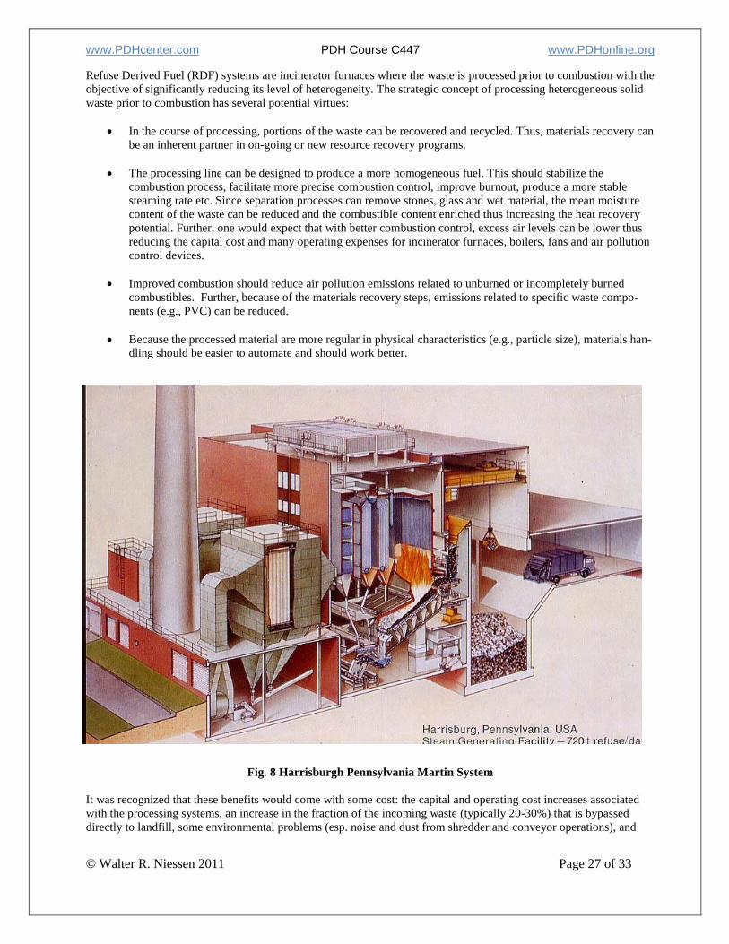
in Figure 8: the original Harrisburg, PA Martin grate design (steeply sloped reciprocating grates pushing “up-hill”),
with electrostatic precipitator air pollution control.
D. Refuse Derived Fuel Systems
www.PDHcenter.com PDH Course C447 www.PDHonline.org
© Walter R. Niessen 2011 Page 27 of 33
Refuse Derived Fuel (RDF) systems are incinerator furnaces where the waste is processed prior to combustion with the
objective of significantly reducing its level of heterogeneity. The strategic concept of processing heterogeneous solid
waste prior to combustion has several potential virtues:
In the course of processing, portions of the waste can be recovered and recycled. Thus, materials recovery can
be an inherent partner in on-going or new resource recovery programs.
The processing line can be designed to produce a more homogeneous fuel. This should stabilize the
combustion process, facilitate more precise combustion control, improve burnout, produce a more stable
steaming rate etc. Since separation processes can remove stones, glass and wet material, the mean moisture
content of the waste can be reduced and the combustible content enriched thus increasing the heat recovery
potential. Further, one would expect that with better combustion control, excess air levels can be lower thus
reducing the capital cost and many operating expenses for incinerator furnaces, boilers, fans and air pollution
control devices.
Improved combustion should reduce air pollution emissions related to unburned or incompletely burned
combustibles. Further, because of the materials recovery steps, emissions related to specific waste compo-
nents (e.g., PVC) can be reduced.
Because the processed material are more regular in physical characteristics (e.g., particle size), materials han-
dling should be easier to automate and should work better.
Fig. 8 Harrisburgh Pennsylvania Martin System
It was recognized that these benefits would come with some cost: the capital and operating cost increases associated
with the processing systems, an increase in the fraction of the incoming waste (typically 20-30%) that is bypassed
directly to landfill, some environmental problems (esp. noise and dust from shredder and conveyor operations), and
www.PDHcenter.com PDH Course C447 www.PDHonline.org
© Walter R. Niessen 2011 Page 28 of 33
risk of injury or equipment outage due to explosions. All of these anticipated "costs" and some that were not antici-
pated have, indeed, been experienced; and often at an unanticipated degree of severity and consequence.
In the development and implementation of technology for mass burn facilities, the vendor firms participating in the
market generally offer complete “chute-to-stack" systems based on conservative, repeat application of well-proven
technological features. Most aspects of the mass burn technology were extensions of combustor concepts developed
and proven in burning coal, lignite and waste fuels such as bagasse. In contrast, many RDF plants incorporate innova-
tive process flowsheets and experiment with untested and unproven items of equipment in the critical RDF processing
and handling areas. The extensive body of design data that supported the early mass burn incinerator designs was
lacking for RDF systems. Further, the lack of overall system vendors for RDF-based systems reduces the feedback of
field experience into process development.
The often-demonstrated characteristic of refuse to profoundly stress, clog, abrade, corrode and otherwise challenge
process and handling equipment made extrapolations from prior experience with other materials uncertain and, quite
often, disappointing. Further, the prime RDF processing devices were connected together with materials handling
systems where critical design parameters were not well understood and where refuse behavior often was found to be
"quite different" from that of reference materials used as the basis for design.
The consequences of these facts and influences were repeated in many if not all plants: long and politically painful
start-up programs requiring considerable re-work of conveyors and processing equipment. This was accompanied by
increases in facility capitalization, higher than anticipated operations and maintenance costs and, often, derating of the
combustor due to limitations in processing and/or feeding systems. Also, from time to time, many plants experienced
explosions, some with lethal consequences, from ignition of combustible vapors released in hammermilling of volatile
hydrocarbon (e.g., gasoline) containers.
Despite these challenges and failures, a maturing technology ultimately emerged. By the early 1990's, "package" RDF
processing facilities with performance guarantees could be procured to generate specification RDF. A vendor
community offering total RDF-based systems was developing. RDF-only and co-combustion of RDF with other
wastes and/or coal was being practiced in several incinerator boiler and utility power plants throughout the United
States. The basic technology had become generally "available." The primary concerns limiting implementation of
RDF-based projects had shifted from one of high perceived technical risk and problematic operability to the more
conventional project development decision criterion: the ordinary issues of cost, permitting, siting, and the like. It may
be significant, however, that now new RDF-based systems have been installed in the U.S. in recent years and several
jurisdictions with RDF systems that have ended their useful life are upgrading or exchanging to mass burn alternatives.
1. RDF Processing
The underlying objectives of incineration using RDF (materials recovery and production of a homogeneous fuel) are
achieved in the processing line. It is here that materials for recycling are recovered (on "picking belts" by human
workers or by automated processes that exploit the physical or chemical characteristics of target refuse components).
Before or after the removal of materials, size reduction and size separation takes place. In all cases, the RDF facility is
heavily involved in materials handling equipment to include a spectrum of loaders, conveyors, hoppers and feeders.
Processing alternatives, performance and utility requirements are described elsewhere [1]. The perverse nature of
refuse with conventional materials handling processes has been the major problem with RDF plants.
2. RDF Combustion Systems
The combustion concepts used in burning RDF fall into two categories: RDF-only combustors and combustors where
RDF is burned as a second fuel along with coal, wood waste or other materials. Since almost all processing concepts
include size reduction and the removal of massive metal material, stones, much of the glass and the very wet wastes,
the remaining fuel is well-suited for partial or complete combustion in which the particles of RDF are suspended in gas
flows. RDF is poorly suited for mass burn grate burning as it tends to blind the grates and inhibit air flow.
Consequently, the types of combustion system used for RDF have focused on the spreader stoker (semi-suspension
burning) using a chain grate (Fig. 5) and several embodiments of full suspension firing.
a. Spreader Stoker Firing
The spreader stoker furnace uses a single, flat traveling grate. The grate moves at a slow, constant rate much as a
conveyor belt. Air is supplied through the grate from one or more undergrate plenums. Waste supplied to the furnace is
typically shredded such that about 95 percent passes a 10.2 cm top-size. Wastes are charged to the furnace using
www.PDHcenter.com PDH Course C447 www.PDHonline.org
© Walter R. Niessen 2011 Page 29 of 33
several mechanical or air-swept feeders mounted on the "front face" of the furnace wall. The feeders cast the feed
over the fire to land on the grate near the rear wall. The grate moves the waste back toward the front face and
discharges ash just below the feeders. All but the very wettest RDF feedstock is dried and ignited in its flight across
the furnace through the flow of hot combustion gases rising from the grate. After landing on the grate, the waste
continues to burn. For design purposes, it is often assumed that 40 to 60 percent of the heat release takes place in
suspension and the remainder on the grate.
Although the RDF preparation step can produce a fuel with considerably greater homogeneity than raw refuse, the
benefits of homogeneity require a steady feed rate. Achieving a uniform feed rate has not proven easy. Hang-ups and
blockage occur in almost all systems. This results in irregular feed rates, heat release and steaming rates.
b. Suspension Burning
The burning of RDF is suspension has been effected in two ways:
● In solid fuel boilers using feeding methods that are similar to those used to fire pulverized coal in
suspension and in vortex furnaces; and
● In fluid bed combustors.
In each case, secondary fuels (coal or other waste streams such as wood scraps, sawdust agricultural wastes or
industrial liquid waste) are often burned at relative heat release rates ranging from zero to many times that of the RDF.
a. RDF and RDF-Coal Burning in Suspension-Fired Boilers. Co-burning of refuse and coal is significantly different
from burning either fuel alone. With co-burning, the combustion environment must be tailored to the limitations
imposed by the poorest fuel. The furnace temperatures will approach that of the dominant (heat release basis) fuel.
The top-size of the RDF used in suspension burning has varied from as small as 0.95 cm to as much as 6.35 cm. The
cost of shredding increases rapidly as the mean particle size decreases. However, larger particles have longer burning
time. One should avoid carry-over of burning RDF fragments because (1) the material can generate clinkers during
burnout in the ash hoppers under the boiler passes or, (2), if applicable, burning "sparklers" cause pinholes in fabric
filters. Therefore, the goal has been to find the largest top size that gives acceptable combustion and minimum
carry-over of burning material from the primary furnace. A maximum particle size between 2.5 and 3.8 cm appears
optimal. A cross-section of the coal-RDF boiler used in Ames, IA is shown in Fig. 9.
From a regulatory standpoint, co-burning RDF and coal offers a significant advantage in comparison to RDF alone. If
the heat release rate due to the refuse is less than 15% of the total heat release, the special U.S. EPA air pollution
emission requirements applicable to “incinerators” does not apply: only the conventional coal emission requirements.
This is an advantage in both permitting and in gaining public acceptance of the system.
b. Fluid Bed Burning. Fluid bed incinerators for RDF were described earlier. Fluidized bed RDF combustion can
involve new plant, stand-alone combustors (followed by boilers) or modification of existing coal furnaces (suspension
fired or stoker fired) to add the distribution plate, high pressure air supply, sand management and other features of a
bubbling fluid bed. RDF, coal, wood or almost any other feedstock that is compatible with a reasonable overall energy
balance can be fed to the bed. Critical requirements are features that can adequately handle the segregation and
discharge of the noncombustible, "tramp material" fed to the system an in-bed boiler tubes to effect heat removal from
the bed. Heat removal allows control of bed temperatures and avoids ash fusion and bed defluidization. Facilities
meeting these requirements were installed in La Crosse, WI and Tacoma, WA.
E. Modular Incinerators
In the 1960s, several manufacturers, recognizing the increasing emphasis on smoke abatement, began producing
incinerators which limited (or starved) the combustion air supplied to the primary chamber to about 80 percent of
theoretical and the overall combustion air to about 120 percent excess. This holds flue gas temperatures high and
minimizes the need and/or fuel consumption for afterburner devices.
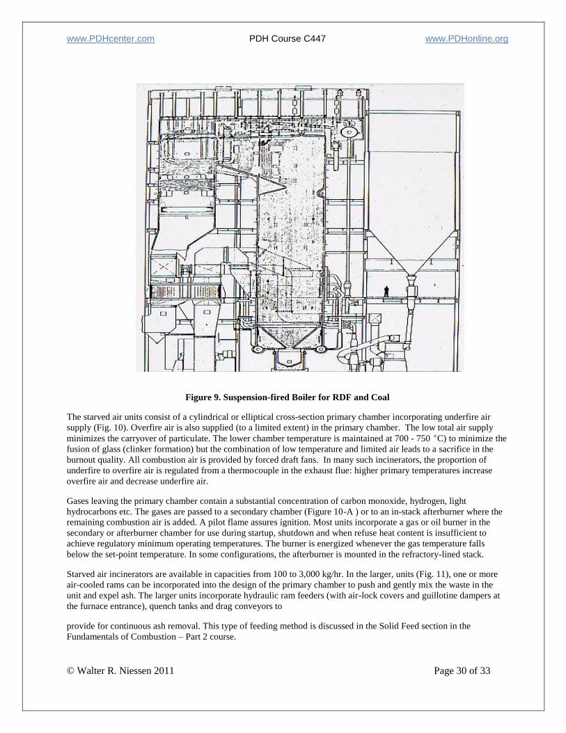
www.PDHcenter.com PDH Course C447 www.PDHonline.org
© Walter R. Niessen 2011 Page 30 of 33
Figure 9. Suspension-fired Boiler for RDF and Coal
The starved air units consist of a cylindrical or elliptical cross-section primary chamber incorporating underfire air
supply (Fig. 10). Overfire air is also supplied (to a limited extent) in the primary chamber. The low total air supply
minimizes the carryover of particulate. The lower chamber temperature is maintained at 700 - 750 C) to minimize the
fusion of glass (clinker formation) but the combination of low temperature and limited air leads to a sacrifice in the
burnout quality. All combustion air is provided by forced draft fans. In many such incinerators, the proportion of
underfire to overfire air is regulated from a thermocouple in the exhaust flue: higher primary temperatures increase
overfire air and decrease underfire air.
Gases leaving the primary chamber contain a substantial concentration of carbon monoxide, hydrogen, light
hydrocarbons etc. The gases are passed to a secondary chamber (Figure 10-A ) or to an in-stack afterburner where the
remaining combustion air is added. A pilot flame assures ignition. Most units incorporate a gas or oil burner in the
secondary or afterburner chamber for use during startup, shutdown and when refuse heat content is insufficient to
achieve regulatory minimum operating temperatures. The burner is energized whenever the gas temperature falls
below the set-point temperature. In some configurations, the afterburner is mounted in the refractory-lined stack.
Starved air incinerators are available in capacities from 100 to 3,000 kg/hr. In the larger, units (Fig. 11), one or more
air-cooled rams can be incorporated into the design of the primary chamber to push and gently mix the waste in the
unit and expel ash. The larger units incorporate hydraulic ram feeders (with air-lock covers and guillotine dampers at
the furnace entrance), quench tanks and drag conveyors to
provide for continuous ash removal. This type of feeding method is discussed in the Solid Feed section in the
Fundamentals of Combustion – Part 2 course.
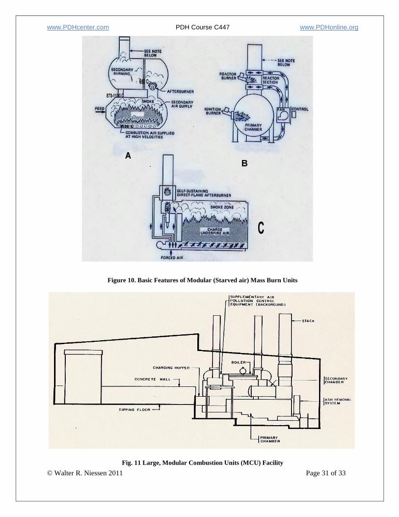
www.PDHcenter.com PDH Course C447 www.PDHonline.org
© Walter R. Niessen 2011 Page 31 of 33
Figure 10. Basic Features of Modular (Starved air) Mass Burn Units
Fig. 11 Large, Modular Combustion Units (MCU) Facility

www.PDHcenter.com PDH Course C447 www.PDHonline.org
© Walter R. Niessen 2011 Page 32 of 33
F. Operations
A comprehensive treatment of the operating problems and challenges of municipal waste incineration would introduce
many new topics. Further, the "rightness" or "wrongness" of many of the recommendations would be subject to
controversy since the human element, leadership styles, cultural effects and the like often produce many good and
workable answers to the same question. However, there is merit is identifying the major operating problems observed
in existing plants as indications to the design engineer that attention is necessary.
Experience based on a study of the equipment of approximately 30 manufacturers in 52 mass burn and modular
incineration plants with heat recovery [6] indicate that refractory problems are the most common, ranging from the
need for minor patching to complete replacement. Minimization of the problem included both attention to avoid
charging bulky, metal wastes and replacement of (softer) castable refractory with more abrasion-resistant, fired brick.
Ash conveyors and problems with controls were also common. In modular combustion units, underfire air ports were
subject to plugging and problems with the charging ram were common. Enlarging of the orifices and periodic steam
purging have been tried to help the problem, but regular maintenance and cleaning is still necessary. Systems with fire
tube boilers also had plugging and corrosion problems.
Many plants complain about the limitations caused by a small tipping floor that causes congestion during deliveries
and does not give room for floor-dumping to inspect incoming waste for auto batteries, hazardous wastes etc. as may
be required by local authorities. Also, complaints called for more attention by the designer to the potential traffic flow
pattern on the tipping floor.
Warping of dampers and charging doors was also common; especially in starved air systems and when units are run at
higher than design temperatures. Similar problems with charging rams were noted although deficiencies in the
hydraulic systems were the prime source of the difficulties.
G. Summary
The sections above provide an introduction to full-combustion alternatives in the thermal processing of domestic solid
waste. There is much more to learn but the insights above provide the basics needed to understand conventional mass
burn and RDF systems; presently responsible for the processing of almost 15% of the waste now generated in the
United States. A second course, Thermal Processing of Domestic Solid Wastes − Conversion Technologies
(gasification, plasma systems etc.) builds on this foundation and indicates the direction of innovation in this important
public services area.
One should realize, however, that the technologies described in the full-combustion course are the “gold standard.”
Particularly for the mass burn options, these systems are offered through multiple source competition between
experienced firms with impressive and extensive track records in meeting budgets and schedules and which meet or
better all air, water and residue-related federal and state regulations. These features should not be taken likely given
the aggressive and unforgiving behavior of domestic waste.
H. References
1. Niessen, W., “Combustion and Incineration Processes, Applications in Environmental Engineering “ 4th Ed.,
Taylor and Francis Group, Boca Raton, FL, 2010
2. U.S. Environmental Protection Agency, “Municipal Solid Waste in the United States: 2005 Facts and Figures,”
USPEA, Office of Solid Waste, EPA530-R-06-011, October 2006
3. U.S. Environmental Protection Agency, “Municipal Solid Waste in the United States: 2007 Facts and Figures,”
USPEA, Office of Solid Waste, EPA530-R-08-010, November 2008
4. Niessen, W.R., and Chansky, S.H., “The Nature of Refuse,” Proc. 1970 ASME Incinerator Conference, ASME,
New York, 1970, Page 1-21
5. Kahn, Z., Renard, M.L. ,and Campbell, J., “Investigation of Engineering and Design Considerations in Selecting
Conveyors for Densified Refuse-Derived Fuel (dRDF) and dRDF-Coal Mixtures”, National Center for Resource
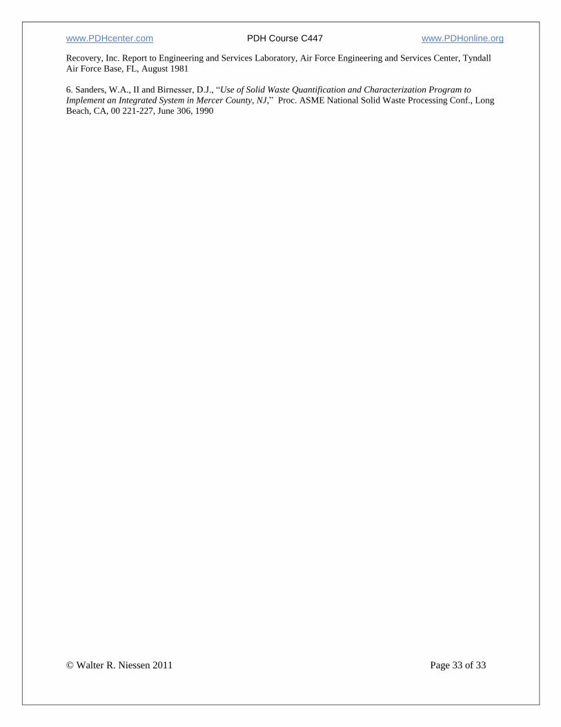
www.PDHcenter.com PDH Course C447 www.PDHonline.org
© Walter R. Niessen 2011 Page 33 of 33
Recovery, Inc. Report to Engineering and Services Laboratory, Air Force Engineering and Services Center, Tyndall
Air Force Base, FL, August 1981
6. Sanders, W.A., II and Birnesser, D.J., “Use of Solid Waste Quantification and Characterization Program to
Implement an Integrated System in Mercer County, NJ,” Proc. ASME National Solid Waste Processing Conf., Long
Beach, CA, 00 221-227, June 306, 1990


![[Walter R. Niessen] Combustion and Incineration Pr(BookFi.org)](https://img.pdfslide.us/doc/110x75/55cf9981550346d0339db69b/walter-r-niessen-combustion-and-incineration-prbookfiorg.jpg)