Embed Size (px)
Citation preview
Thermal Performance Research –Part 1
April 2016 Webinar
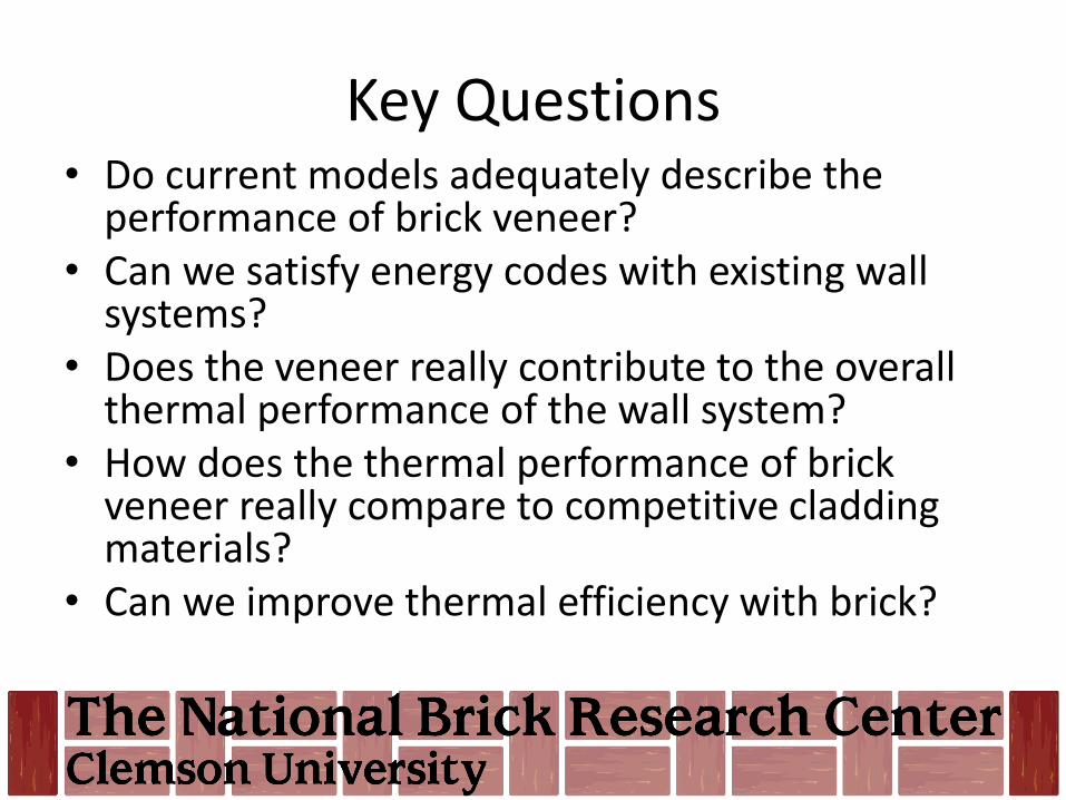
Key Questions• Do current models adequately describe the
performance of brick veneer?• Can we satisfy energy codes with existing wall
systems?• Does the veneer really contribute to the overall
thermal performance of the wall system?• How does the thermal performance of brick
veneer really compare to competitive cladding materials?
• Can we improve thermal efficiency with brick?
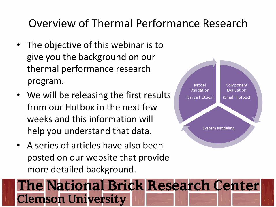
Overview of Thermal Performance Research
• The objective of this webinar is to give you the background on our thermal performance research program.
• We will be releasing the first results from our Hotbox in the next few weeks and this information will help you understand that data.
• A series of articles have also been posted on our website that provide more detailed background.
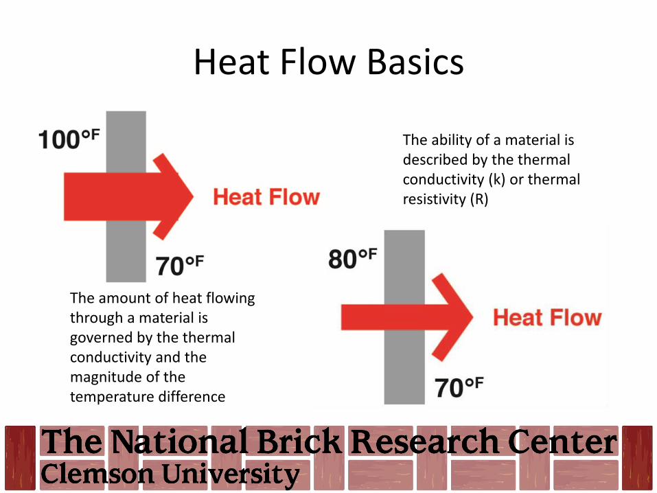
Heat Flow Basics
The ability of a material is described by the thermal conductivity (k) or thermal resistivity (R)
The amount of heat flowing through a material is governed by the thermal conductivity and the magnitude of the temperature difference
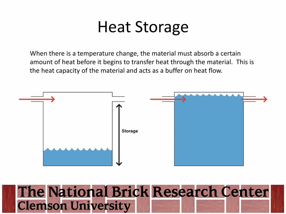
Heat Storage
When there is a temperature change, the material must absorb a certain amount of heat before it begins to transfer heat through the material. This is the heat capacity of the material and acts as a buffer on heat flow.

Typical Thermal Properties and UnitsTerm Symbol Definition Metric Units Imperial Units
Heat Flow Q The quantity of heat energy transferred in a unit of time
W Btu/h
Heat Flux q The rate of heat flow through a surface of unit area perpendicular to the direction of
heat flow
W/m2 Btu/h ft2
Temperature gradient
ΔT Temperature difference across a surface °C or K °F
Thermal Conductance
C Heat flux per unit of temperature difference W/m2 K Btu/h ft2 F
Thermal Conductivity
k The time rate of steady state heat flow through a unit area of material induced by a
temperature gradient
W/m K Btu in./h ft2 F
Thermal Resistance R Reciprocal of thermal conductance K m2/W h ft F/Btu
Specific Heat or Heat Capacity
Cp The quantity of heat energy required to change the temperature of a unit mass of a
substance by one degree
J/kg K Btu/lb F
Density ρ Kg/m3 Lbs/ft3

Heat Flow
Transient heat flow through a wall can be described by the following differential equation:
Where:• T is temperature, • t is time, • x is distance• α is a material property known as thermal diffusivity.
2
2
dx
Td
dt
dT

Thermal Diffusivity
The thermal diffusivity (α) depends on the type of materials used in the wall.
Where• k is the thermal conductivity of the material, • ρ is the density of the material and • CP is the specific heat of the material.
PC
k
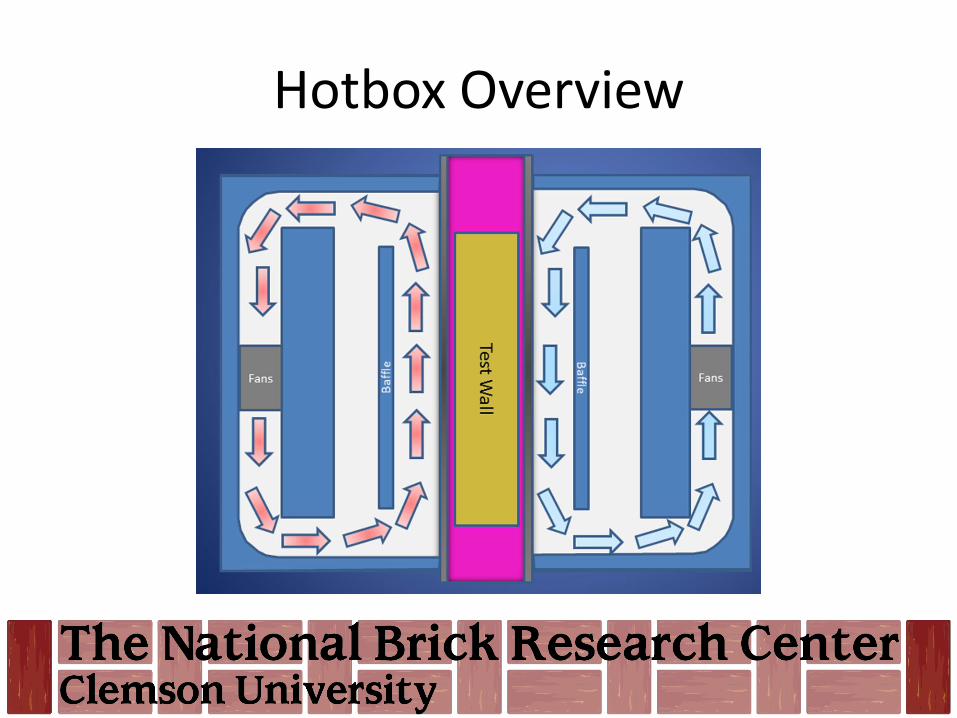
Hotbox Overview
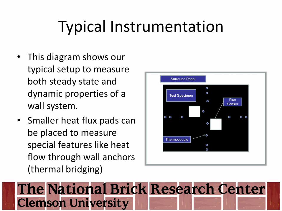
Typical Instrumentation
• This diagram shows our typical setup to measure both steady state and dynamic properties of a wall system.
• Smaller heat flux pads can be placed to measure special features like heat flow through wall anchors (thermal bridging)
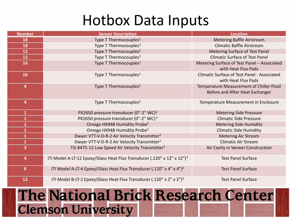
Hotbox Data InputsNumber Sensor Description Location
18 Type T Thermocouples1 Metering Baffle Airstream18 Type T Thermocouples1 Climatic Baffle Airstream12 Type T Thermocouples1 Metering Surface of Test Panel12 Type T Thermocouples1 Climatic Surface of Test Panel16 Type T Thermocouples1 Metering Surface of Test Panel – Associated
with Heat Flux Pads16 Type T Thermocouples1 Climatic Surface of Test Panel - Associated
with Heat Flux Pads4 Type T Thermocouples1 Temperature Measurement of Chiller Fluid
Before and After Heat Exchanger
4 Type T Thermocouples1 Temperature Measurement in Enclosure
1 PX2650 pressure transducer (0"‐2" WC)2 Metering Side Pressure1 PX2650 pressure transducer (0"‐2" WC) 2 Climatic Side Pressure1 Omega HX94B Humidity Probe2 Metering Side Humidity1 Omega HX94B Humidity Probe2 Climatic Side Humidity1 Dwyer VTT‐V‐D‐R‐2 Air Velocity Transmitter2 Metering Air Stream1 Dwyer VTT‐V‐D‐R‐2 Air Velocity Transmitter2 Climatic Air Stream3 TSI 8475‐12 Low Speed Air Velocity Transmitter2 Air Cavity in Veneer Construction
4 ITI Model A‐LT‐12 Epoxy/Glass Heat Flux Transducer (.120" x 12" x 12")3 Test Panel Surface
8 ITI Model A‐LT‐4 Epoxy/Glass Heat Flux Transducer (.120" x 4" x 4")3 Test Panel Surface
12 ITI Model B‐LT‐2 Epoxy/Glass Heat Flux Transducer (.120" x 2" x 2")3 Test Panel Surface
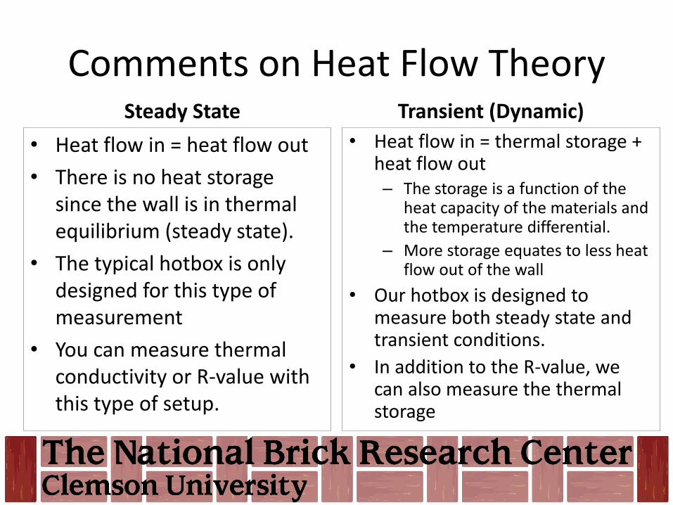
Comments on Heat Flow TheorySteady State
• Heat flow in = heat flow out
• There is no heat storage since the wall is in thermal equilibrium (steady state).
• The typical hotbox is only designed for this type of measurement
• You can measure thermal conductivity or R-value with this type of setup.
Transient (Dynamic)
• Heat flow in = thermal storage + heat flow out– The storage is a function of the
heat capacity of the materials and the temperature differential.
– More storage equates to less heat flow out of the wall
• Our hotbox is designed to measure both steady state and transient conditions.
• In addition to the R-value, we can also measure the thermal storage
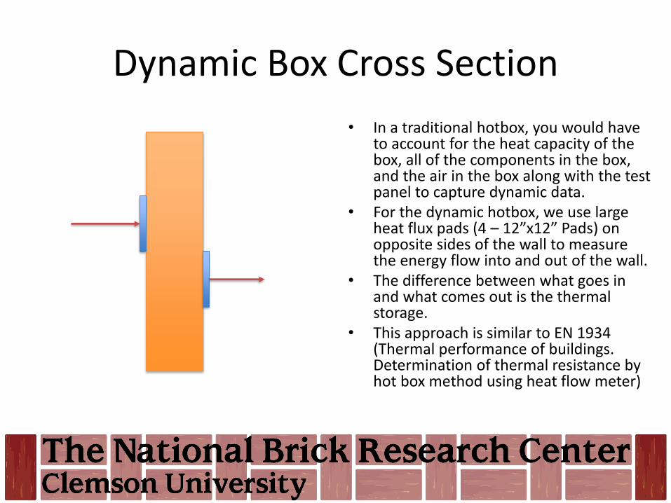
Dynamic Box Cross Section
• In a traditional hotbox, you would have to account for the heat capacity of the box, all of the components in the box, and the air in the box along with the test panel to capture dynamic data.
• For the dynamic hotbox, we use large heat flux pads (4 – 12”x12” Pads) on opposite sides of the wall to measure the energy flow into and out of the wall.
• The difference between what goes in and what comes out is the thermal storage.
• This approach is similar to EN 1934 (Thermal performance of buildings. Determination of thermal resistance by hot box method using heat flow meter)
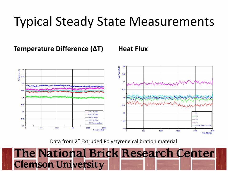
Typical Steady State Measurements
Temperature Difference (ΔT) Heat Flux
Data from 2” Extruded Polystyrene calibration material
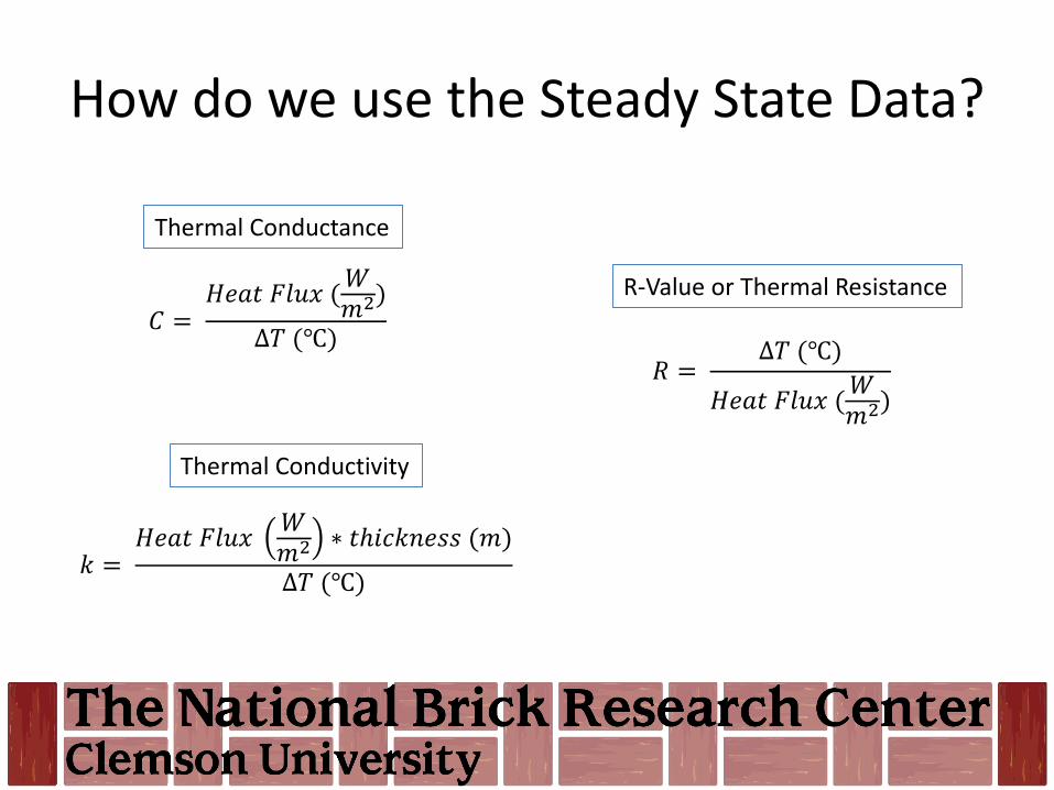
How do we use the Steady State Data?
𝐶 =𝐻𝑒𝑎𝑡 𝐹𝑙𝑢𝑥 (
𝑊𝑚2)
∆𝑇 (℃)
𝑘 =𝐻𝑒𝑎𝑡 𝐹𝑙𝑢𝑥
𝑊𝑚2 ∗ 𝑡ℎ𝑖𝑐𝑘𝑛𝑒𝑠𝑠 (𝑚)
∆𝑇 (℃)
𝑅 =∆𝑇 (℃)
𝐻𝑒𝑎𝑡 𝐹𝑙𝑢𝑥 (𝑊𝑚2)
R-Value or Thermal Resistance
Thermal Conductivity
Thermal Conductance

Heat Flux and ΔT for Calibration Materials
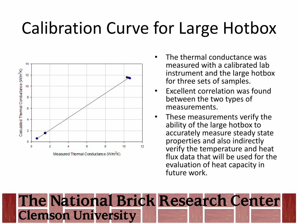
Calibration Curve for Large Hotbox
• The thermal conductance was measured with a calibrated lab instrument and the large hotbox for three sets of samples.
• Excellent correlation was found between the two types of measurements.
• These measurements verify the ability of the large hotbox to accurately measure steady state properties and also indirectly verify the temperature and heat flux data that will be used for the evaluation of heat capacity in future work.

Transient (Step) Measurements
Climactic
Metering
Climactic
Metering
• The difference between the heat in and the heat out is due to thermal storage.• The storage also results in a temperature lag between the climatic (hot) and metering
(cold) faces.
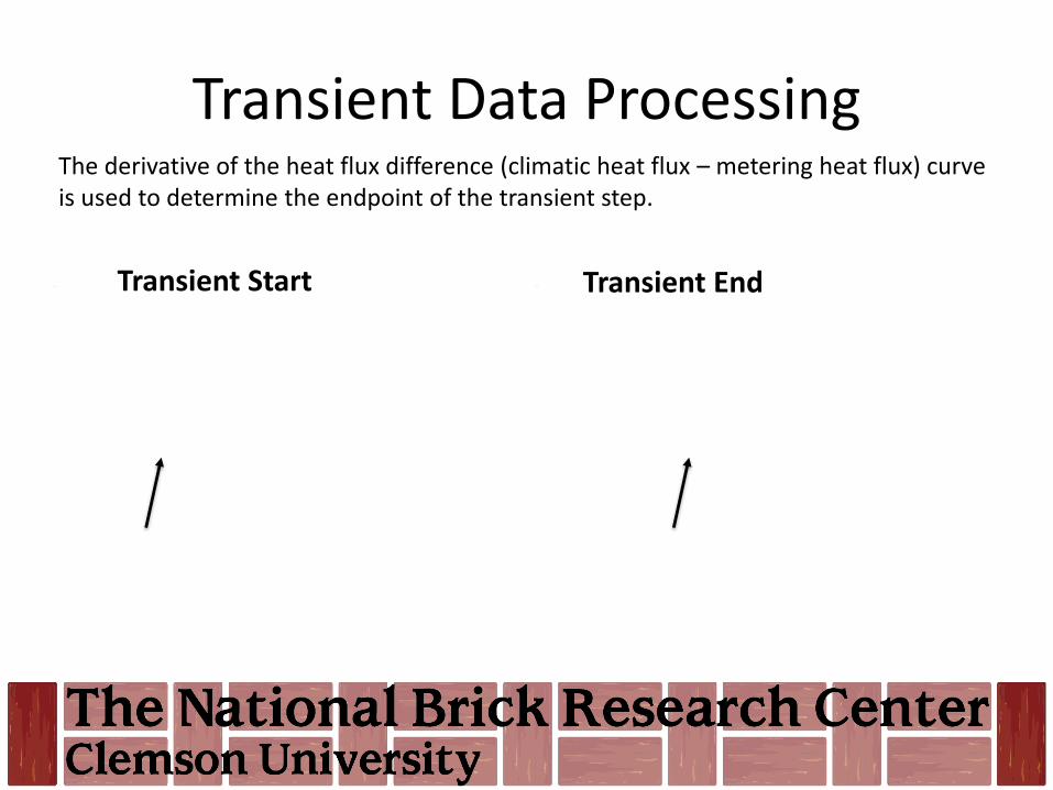
Transient Data Processing
Transient Start Transient End
The derivative of the heat flux difference (climatic heat flux – metering heat flux) curve is used to determine the endpoint of the transient step.
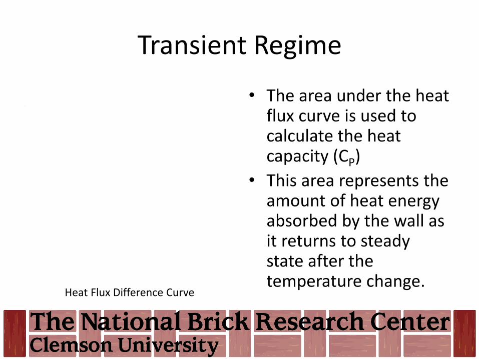
Transient Regime
• The area under the heat flux curve is used to calculate the heat capacity (CP)
• This area represents the amount of heat energy absorbed by the wall as it returns to steady state after the temperature change.
Heat Flux Difference Curve

UNIT TESTING

Unit Testing
• We intend to build a database of thermal properties that are a function of size, coring configuration, and density.
• This data can then be used to verify the data used in existing models. This is especially critical for heat capacity.
• We will also use the data in our modelling effort.
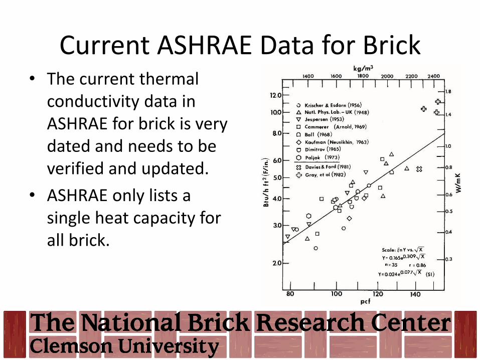
Current ASHRAE Data for Brick• The current thermal
conductivity data in ASHRAE for brick is very dated and needs to be verified and updated.
• ASHRAE only lists a single heat capacity for all brick.
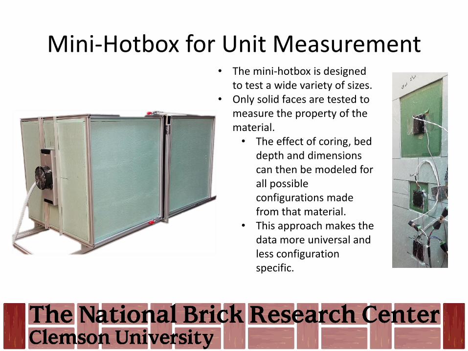
Mini-Hotbox for Unit Measurement• The mini-hotbox is designed
to test a wide variety of sizes.• Only solid faces are tested to
measure the property of the material.• The effect of coring, bed
depth and dimensions can then be modeled for all possible configurations made from that material.
• This approach makes the data more universal and less configuration specific.

MODELLING
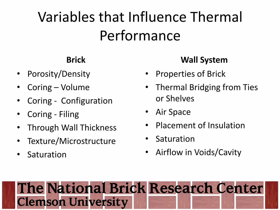
Variables that Influence Thermal Performance
Brick
• Porosity/Density
• Coring – Volume
• Coring - Configuration
• Coring - Filing
• Through Wall Thickness
• Texture/Microstructure
• Saturation
Wall System
• Properties of Brick
• Thermal Bridging from Ties or Shelves
• Air Space
• Placement of Insulation
• Saturation
• Airflow in Voids/Cavity
Modelling Steps• Define the geometry• Assign material properties
– The thermal “connection” between dissimilar materials also has to be defined (example – mortar in the core holes)
• “Mesh” the model – This is breaking a big problem down into a large number of small pieces (nodes)
that can be solved individually.
• Assign boundary conditions– In our case this is the air flow and temperature conditions that we measured in
the hotbox.
• Solve the model– The results for each node are calculated sequentially.– A transient model requires a large number of iterations for each of the small
pieces.
• Evaluate the results and improve the model as necessary.

Meshing Comparison
Hex Mesh Tetragonal Mesh
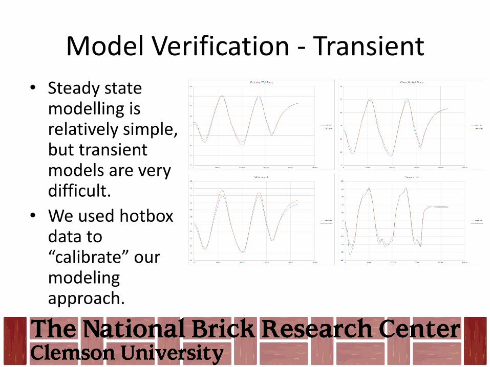
Model Verification - Transient
• Steady state modelling is relatively simple, but transient models are very difficult.
• We used hotbox data to “calibrate” our modeling approach.
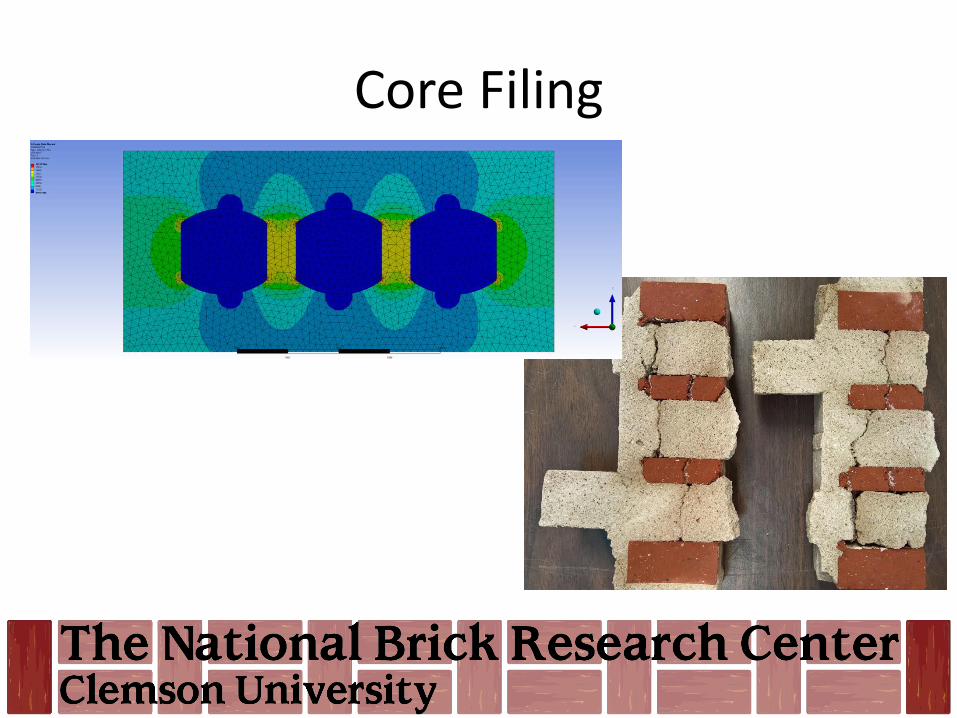
Core Filing

Modeling Demonstration
What’s next?
• We will present the initial results of our work with a typical veneer wall system at the May meeting.
• We will continue to publish articles on our website detailing these results.
• We will continue to refine our mini-hotbox and modelling efforts.
• Working with our wall systems committee we will begin a series of measurements on the effect of ties and shelf angles on ‘thermal bridging’.