Embed Size (px)
Citation preview
Brazilian Journalof ChemicalEngineering
Vol. 36, No. 02, pp. 869 - 883, April - June, 2019dx.doi.org/10.1590/0104-6632.20190362s20180424
ISSN 0104-6632 Printed in Brazil
www.abeq.org.br/bjche
THERMAL PERFORMANCE OF ONE-PASSSHELL-AND-TUBE HEAT EXCHANGERS
IN COUNTER-FLOWFelipe C. Magazoni1, Luben Cabezas-Gómez1*,Pablo F. Alvariño2 and José M. Saiz-Jabardo1
* Corresponding author: L. Cabezas-Gómez - E-mail: [email protected]
1 Universidade de São Paulo, Escola de Engenharia de São Carlos, Departamento de Engenharia Mecânica, São Carlos, SP, Brasil.E-mail: [email protected] - ORCID: 0000-0002-9550-9453
2 Universidade da Coruña, Escola Politécnica Superior, Coruña, Spain. ORCID: 0000-0002-9598-5249
(Submitted: September 5, 2018 ; Revised: January 31, 2019 ; Accepted: February 24, 2019)
Abstract - A computational methodology is proposed and applied to calculate the temperature effectiveness, P, and the logarithmic mean temperature difference (LMTD) correction factor, F, of TEMA E shell-and-tube heat exchangers with one-pass and fluids flowing in counter-flow. An arbitrary number of baffles is considered along with three different mixture conditions of the shell-side fluid. The methodology is based on various modeling considerations adopted in several publications addressing crossflow and shell-and-tube heat exchangers. Each section between two baffles is idealized as a crossflow heat exchanger with different shell-side mixing conditions. The obtained results are compared to available solutions from the literature, showing a very good agreement. New closed-form mathematical P relations and approximate F correlations depending on the number of baffles, very appropriate for preliminary computerized analysis and design procedures, are provided. A theoretical study about the influence of the number of baffles and two shell-side fluid mixing hypotheses over P and F values is presented. The proposed methodology could be used to obtain P and F values for a particular arrangement of 1-1 shell-and-tube heat exchanger.Keywords: 1-1 TEMA E shell-and-tube heat exchangers; Temperature effectiveness; LMTD correction factor.
INTRODUCTION
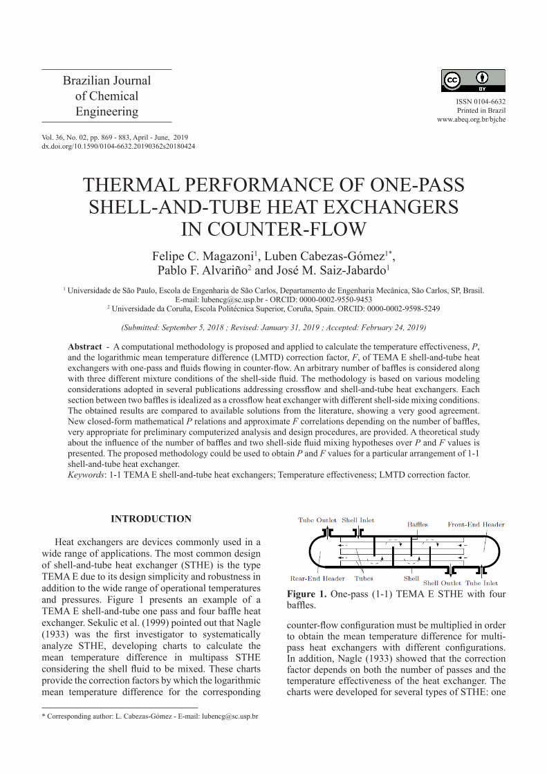
Heat exchangers are devices commonly used in a wide range of applications. The most common design of shell-and-tube heat exchanger (STHE) is the type TEMA E due to its design simplicity and robustness in addition to the wide range of operational temperatures and pressures. Figure 1 presents an example of a TEMA E shell-and-tube one pass and four baffle heat exchanger. Sekulic et al. (1999) pointed out that Nagle (1933) was the first investigator to systematically analyze STHE, developing charts to calculate the mean temperature difference in multipass STHE considering the shell fluid to be mixed. These charts provide the correction factors by which the logarithmic mean temperature difference for the corresponding
Figure 1. One-pass (1-1) TEMA E STHE with four baffles.
counter-flow configuration must be multiplied in order to obtain the mean temperature difference for multi-pass heat exchangers with different configurations. In addition, Nagle (1933) showed that the correction factor depends on both the number of passes and the temperature effectiveness of the heat exchanger. The charts were developed for several types of STHE: one
Felipe C. Magazoni et al.
Brazilian Journal of Chemical Engineering
870
pass on shell-side and two or more passes on tube-side (1-2; 1-4; 1-6; etc.); two passes on shell-side and four or more passes on tube-side (2-4; 2-8; 2-16; etc.).
After Nagle (1933), other authors provided different solutions for several STHE. Important contributions are those by Underwood (1934), Bowman (1936), Fischer (1938), Bowman et al. (1940), Gardner (1941), Kraus and Kern (1965), and Gardner and Taborek (1977). Underwood (1934) obtained the first closed-form solutions for 1-2 and 1-4 TEMA E STHE in terms of the true mean temperature difference by direct integration of the corresponding differential equations. Bowman (1936), based on the Underwood (1934) solution, extended the Nagle (1933) results to obtain data for computing the correction factor for shells with two, three, four, and six passes and the respective even duplicate number of tube-fluid passes. Fischer (1938) derived correction factors for 1-3, 2-6, 3-9, and 4-12 STHE, presenting the results under the same form as Nagle (1933). Bowman et al. (1940) presented an in-depth analysis of multi-pass STHE, summarizing the previous literature. Gardner (1941) presented correction factors for shell-and-tube heat exchangers considering the shell fluid to be unmixed for 1-2, 1-4, 1-6, 1-8, 1-n, and 2-4 STHE, where n is an even number of tube fluid passes. Kraus and Kern (1965) solved the problem of 1-2 and 2-4 TEMA E STHE with one shell pass and even number of tube passes using a direct integration method. Gardner and Taborek (1977) obtained a reappraisal of the mean temperature difference in heat exchangers. They addressed three main aspects of the correction factor: the implication of the assumption of constant global heat exchanger coefficient on the correction factor, the effects of the bypass due to the use of baffles, and the number of baffles.
In another study, Pignotti (1986), using a generalized matrix formalism method based on the work by Domingos (1969), obtained analytical relations to compute the correction factor for TEMA E 1-2 and TEMA J STHE with a few baffles. The author considered the shell-side fluid to be unmixed inside baffle compartments and mixed between baffles compartments. The in-tube fluid was considered to be completely mixed, inside and between baffle compartments. This hypothesis corresponds to the consideration of a heat exchanger with few tubes. Pignotti and Tamborenea (1988) determined the thermal effectiveness of a TEMA E STHE with one shell pass and an arbitrary number of tube fluid passes, n, (1-n TEMA E) as a function of the number of transfer units and heat capacity rate ratio. As the number of tube passes increases, the solution obtained becomes more complicated, rapidly approaching an asymptotic limit.
Hess (1985) studied the 1-5 TEMA E STHE with one shell pass and five tube passes. For this heat exchanger, a completely closed form solution was found and a polynomial approximation was developed that yielded the effectiveness as a function of the heat capacity rate ratio and the number of transfer units. The influence of a finite number of baffles on heat transfer performance for several types of STHE, such as 1-1, 1-2 and 1-n TEMA E, 1-2 TEMA J, and 1-2 TEMA G and H single-phase, was also presented by Shah and Pignotti (1997). New tabular results were provided for TEMA G and H in addition to TEMA E and J heat exchangers for which graphical results were available.
As pointed out by Gardner and Taborek (1977), several studies have been performed in the literature to correlate the shell side heat transfer coefficient in 1-1 TEMA E exchangers with few baffles, assuming a behavior of a true counter-flow (F = 1) configuration. This consideration can lead to possible errors that are difficult to assess and can be avoided using the appropriate values of the F correction factor or of the temperature effectiveness P.
Few studies have addressed the determination of F and P for 1-1 TEMA E STHE. The one by Caglayan and Buthod (1976) analyzed the influence of the baffles with fluids flowing in counter-flow. The STHE was idealized with each baffle section as an unmixed-unmixed crossflow heat exchanger (CFHE). The shell-side fluid at the exit of the baffle section was considered to be mixed (window region), entering with a corresponding mean temperature into the next baffle section. The tube fluid was considered to be unmixed over the whole heat exchanger. This last hypothesis corresponds to the considerations of a great number of tubes inside the shell. The problem was analyzed numerically by a finite difference method for several numbers of baffles (2, 3, 4, 5 and 7 baffle compartments). For all practical purposes, the influence of the finite number of baffles on the temperature effectiveness for a 1-1 TEMA E heat exchanger is found to be negligible for Nb > 6, Nb being the number of baffles.
Gardner and Taborek (1977) analyzed the same kind of STHE considering almost the same assumptions adopted in Caglayan and Buthod (1976). The only difference is that Gardner and Taborek (1977) considered the tube fluid to be perfectly mixed between any two adjoining baffle compartments. They concluded that a minimum of ten baffles are required for a 1-1 STHE to behave as a pure counter-flow one. Shah and Pignotti (1997) summarized the results from the literature for 1-1 TEMA E heat exchangers with both fluids flowing in the counter-flow configuration. They stated that, for a number of baffles larger than ten, the influence of the finite number of baffles on the temperature effectiveness is not significantly larger than 2 %.
Thermal Performance of One-Pass Shell-and-Tube Heat Exchangers in Counter-Flow
Brazilian Journal of Chemical Engineering, Vol. 36, No. 02, pp. 869 - 883, April - June, 2019
871
Several studies presented different optimization techniques for designing STHE for various industrial and research applications using the LMTD method (Amini and Bazargan, 2014; Caputo et al., 2008; Fettaka et al., 2013; Onishi et al., 2013; Sanaye and Hajabdollahi, 2010; Selbas et al., 2006). Almost all these works use the F factor for computing the heat transfer rate and the corresponding heat exchanger size. They explore different techniques to obtain optimized solutions considering the cost and thermodynamic parameters as objective functions.
Computational Fluid Dynamics (CFD) techniques were used in several works to study the thermo hydraulic characteristics and performance of 1-1 STHE (Ozden and Tari, 2010; Chen et al., 2014; Yang et al., 2014a; Yang et al., 2014b; Pal et al., 2016; Batalha Leoni et al., 2017; Mellal et al., 2017; Wang et al., 2018, among others). These studies mainly focus on baffle spacing, baffle cut, baffle configuration, leakage, and orientation influence on the heat transfer coefficient and the pressure drop using free and commercial CFD packages. Some of these studies compare the CFD results with those obtained with the LMTD method using the Kern (1950) and/or Bell-Delaware (Bell, 1981) methodologies (Ozden and Tari, 2010; Yang et al., 2014a; Pal et al., 2016, and Mellal et al., 2017). In these cases, the F factor might be needed when heat exchangers with few baffles are considered. Almost all cited works assumed a unitary value for F.
Commercial software and computational procedures that do not employ correction factor charts and do not rely on CFD techniques are used extensively for the design of heat exchangers in practice. These tools might either be based on the discretization or incremental procedures, such as the HTRI (Heat Transfer Research, Inc.) and the Aspen Heat Design and Rating (EDR) software, or on the use of the so-called “dynamic distributed” models (Coletti and Maccietto, 2011; Diaz-Bejarano et al., 2017 and 2018) to design and analyze the behavior of shell-and-tube heat exchangers. Other procedures not cited could be available for STHE design, considering that these heat exchangers are the most used in industrial, commercial and research applications.
1-1 TEMA E STHE with both fluids flowing in counter-flow are addressed in the present paper. The main objective of the present paper is to provide a quantitative analysis of the influence of the number of baffles on the F and P values for 1-1 TEMA E STHE with both fluids flowing in a counter-flow configuration. Two mixture conditions of the shell-side fluid are addressed. Results are compared to available solutions obtained elsewhere in the literature, demonstrating the capability of the proposed methodology.
The main contributions are the following:- A theoretical study is performed about the influence
of the number of baffles and two shell side fluid mixture
conditions on the temperature effectiveness P and the F factor values for 1-1 TEMA E STHE with both fluids flowing in a counter-flow configuration.
- New closed form expressions for P and approximate relations for the F factor are provided for two of the shell-side fluid mixture conditions as a function of the number of baffles. More relations can be accessed in the authors’ recent work, Magazoni et al. (2019).
- The computational procedure presented can be used to obtain values of P and the F coefficient for a particular arrangement of 1-1 STHE, different than those presented in the paper.
METHODOLOGY
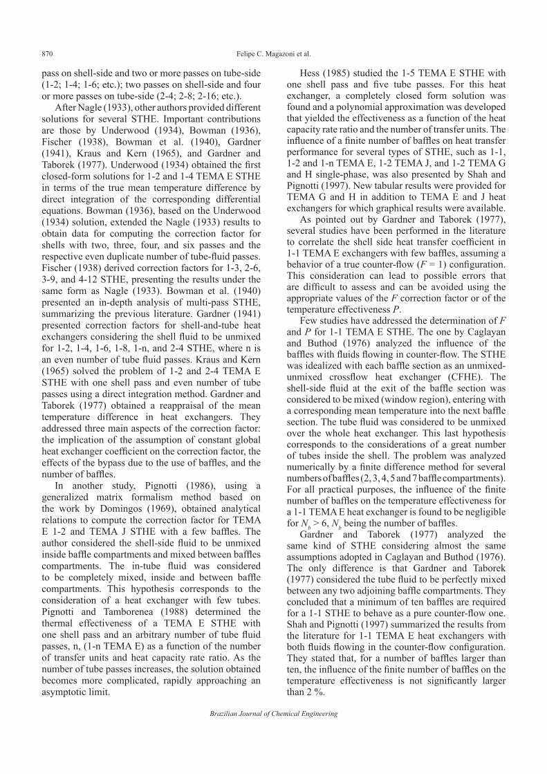
The methodology developed in the present study is based on a procedure to determine the temperature effectiveness P and the correction factor F of a 1-1 TEMA E shell-and-tube heat exchanger with fluids flowing in a counter-flow configuration, as illustrated in Figure 1. The proposed model assumes that the 1-1 TEMA E STHE is equivalent to a succession of crossflow heat exchangers (CFHE), each one encompassing the space between baffles, as illustrated in Figure 2 for a STHE with a single baffle. Thus, the number of crossflow heat exchangers must be equal to the number of baffles plus one.
The following preliminary assumptions are basic for the development of the shell-and-tube heat exchanger model:
(i) There are no leakages and/or bypasses of the shell-side fluid in the STHE. This might be a limitation of the present model, considering that these occurrences are frequent on the shell side. However, Roetzel and Lee (1994) studied experimentally the effect of baffle/shell leakage flow on heat transfer in STHE. Their first conclusion was that baffle/shell leakage flow causes a reduction in the thermal performance and in the apparent “equivalent” overall heat transfer coefficient. Gardner and Taborek (1977) also studied the bypass or leakages effects, stating that these phenomena penalize the heat transfer processes and diminish the heat exchanger performance. Apparently, those studies relate the general decremental effect on the performance of the heat exchanger to the overall heat transfer coefficient. As a result, the complexity added to the model by the inclusion of leakages/bypasses might be circumvented by an adequate correction of the overall heat transfer coefficient that incorporates those effects. This correction is implicit in the present model.
(ii) The tube-side fluid of the STHE is assumed to be unmixed. This is consistent with the assumption of a large number of tubes, commonly used in the literature (Underwood 1934; Bowman 1936; Fischer 1938; Bowman et al., 1940; Gardner 1941; Gardner
Felipe C. Magazoni et al.
Brazilian Journal of Chemical Engineering
872
and Taborek 1977; Shah and Pignotti, 1997; and others).
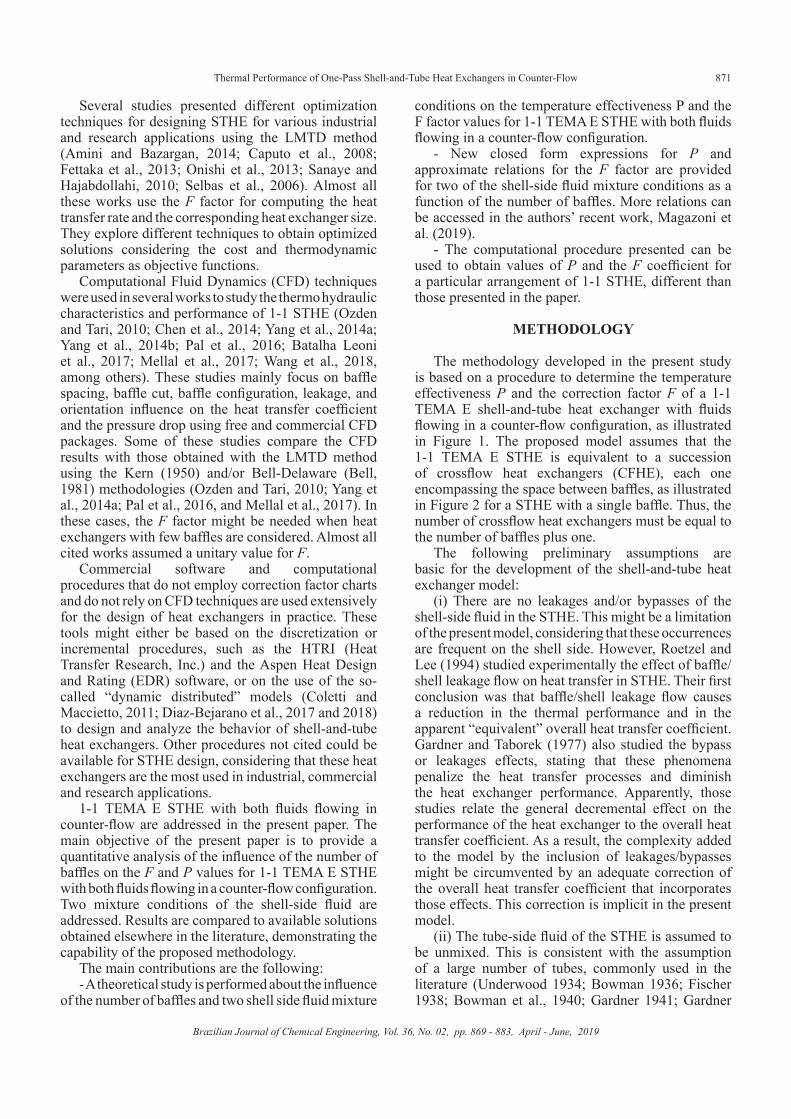
(iii) Two mixing models for the shell-side fluid are considered. One, which is frequently applied in the open literature (Underwood 1934; Bowman 1936; Fischer 1938; Bowman et al., 1940; Gardner 1941; Gardner and Taborek 1977; Shah and Pignotti, 1997; and others), assumes that the shell-side fluid mixes only in the passage between two adjacent regions separated by the baffles, see Figure 3(a). This corresponds to a STHE without a significant mixture of shell-side fluid during the flow across the tube array, but with a significant mixture in the window zone, i.e., the passage between regions separated by baffles. The other, not as common as the first one, assumes that the STHE shell-side fluid mixes as it flows across the bank of tubes, see Figure 3 (b), due to an excessive shell-side fluid turbulence.
(iv) Considering the crossflow heat exchanger (CFHE), the external and in-tube fluids correspond, respectively, to tube and external fluids in the STHE. Thus, the external fluid of the CFHE is fully unmixed in all the heat exchangers, whereas for the in-tube fluid, the shell side mixing models for the STHE must be considered. In the first, more common, the external fluid is unmixed in each CFHE pass, mixing occurring during the pass from one region to the succeeding one, as in Figure 3(a). The second stands for the external fluid fully mixed in the whole CFHE, as in Figure 3(b).
Numerical procedure for P and F calculationFigure 2(a) displays the layout of a one baffle
1-1 TEMA E shell-and-tube heat exchanger with
fluids flowing in a counter-flow configuration. Figure 2(b) shows its schematic representation, where each crossflow zone is modeled as an individual CFHE (Caglayan and Buthod, 1976; Gardner and Taborek, 1977; Shah and Pignotti, 1997). The STHE shell-side and in-tube fluids follow the mixing hypotheses just commented and shown in Figure 3. Figure 3(a) shows the same configuration exhibiting the adopted CFHE first mixing model in more detail. In this case, the one baffle 1-1 TEMA E shell-and-tube heat exchanger is equivalent to an array of two identical pure unmixed-unmixed CFHE arranged in a counter-flow configuration with an infinite number of tubes per pass and two in-tube fluid passes. As noted in Figure 3(a), the in-tube fluid of the CFHE mixes between the passes. This flow arrangement is commonly denominated as a two-pass counter-crossflow heat exchanger with the in-tube fluid mixed between passes (Roetzel and Spang, 2010).
The configurations of CFHE simulated in the present work are counter-crossflow configurations with the external fluid unmixed, but considering two
Figure 2. Modeling of a one baffle 1-1 TEMA E STHE as a set of CFHE.
Figure 3. Mixture conditions hypotheses for the shell-side fluid in each compartment and between baffle compartments.
Thermal Performance of One-Pass Shell-and-Tube Heat Exchangers in Counter-Flow
Brazilian Journal of Chemical Engineering, Vol. 36, No. 02, pp. 869 - 883, April - June, 2019
873
mixture models for the in-tube fluid, shown in Figures 3(a) and (b) in a schematic manner. The first mixing model is the one that corresponds to a perfect mixing of the in-tube fluid at the end of each pass, as Figure 3(a) illustrates. The other mixing model is the one where the in-tube fluid flows perfectly mixed in each pass, corresponding to a single in-tube circuit over the whole heat exchanger, as shown in Figure 3(b).
Due to the fact that the mixing configuration of Figure 3(a) is the most commonly used for modeling STHE, the simulation results of the present paper will be obtained for this mixing model, though a comparison of results from both mixing models will be discussed further on.
The following assumptions, which can also be found in the literature (see, for example, Kays and London (1998), Shah and Sekuliç (2003), Cabezas-Gómez et al. (2015), among others), are basic for the numerical modeling of the crossflow heat exchangers: (i) the heat exchanger operates under steady-state conditions; (ii) Negligible heat losses to the surroundings; (iii) There are no thermal energy sources or sinks in the heat exchanger walls or fluids; (iv) The tube side fluid is perfectly mixed in the tube cross section, its temperature varying nonlinearly along the tube axis (linearly in relation to enthalpy); (v) The external fluid is unmixed; (vi) Heat transfer coefficients and transport properties of the fluids and heat exchanger walls are constant; (vii) Negligible axial heat transfer in the solid walls and fluids; (viii) There is no phase change in either stream.
The determination of the correction coefficient, F, and the temperature effectiveness, P, requires the availability of the inlet and outlet mean temperatures of both fluids, which are obtained using the methodology suggested by Pignotti and Cordero (1983), and later on modified and applied by Magazoni and Cabezas-Gómez (2016). For convenience, the external fluid of the CFHE is cool, whereas the in-tube (internal) fluid is the hot one. However, the results would not change with a shift in the hot-cold fluid assumption.
The logarithm mean temperature correction coefficient, F, can then be determined according to the following expressions (Pignotti and Cordero, 1983):
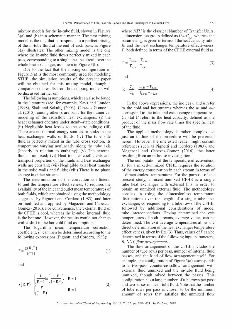
where NTU is the classical Number of Transfer Units, a dimensionless group defined as UA/Cmin, whereas the parameter, χ, is given in terms of the heat capacity ratio, R, and the heat exchanger temperature effectiveness, P, both defined in terms of the CFHE external fluid as,
( )R,PF
NTUχ
=
and
( )
( )
1 1 Pln , R 1R 1 1 RP
R,PP , R 1
1 P
− ≠ − − χ = = −
c,out c,in
h,in c,in
T TP
T T−
=−
and
h,in h,outc
h c,out c,in
T TCR
C T T−
= =−
In the above expressions, the indices c and h refer to the cold and hot streams whereas the in and out correspond to the inlet and exit average temperatures. Capital C refers to the heat capacity, defined as the product of the mass flow rate times the specific heat of the fluid.
The applied methodology is rather complex, so just an outline of the procedure will be presented herein. However, the interested reader might consult references such as Pignotti and Cordero (1983), and Magazoni and Cabezas-Gómez (2016), the latter resulting from an in-house investigation.
The computation of the temperature effectiveness, P, for a mixed-unmixed CFHE requires the solution of the energy conservation in each stream in terms of a dimensionless temperature. For the purpose of the present study, a mixed-unmixed CFHE is a single tube heat exchanger with external fins in order to obtain an unmixed external fluid. The methodology consists in using the dimensionless temperature distributions over the length of a single tube heat exchanger, corresponding to a tube row of the CFHE, followed by additional considerations of model tube interconnections. Having determined the exit temperatures of both streams, average values can be determined. The exit average temperatures allow the direct determination of the heat exchanger temperature effectiveness, given by Eq. (3). Thus, values of P can be determined in terms of the following input parameters: R, NUT, flow arrangement.
The flow arrangement of the CFHE includes the number of tube rows per pass, number of internal fluid passes, and the kind of flow arrangement itself. For example, the configuration of Figure 3(a) corresponds to a two-pass counter-crossflow arrangement with external fluid unmixed and the in-tube fluid being unmixed, though mixed between the passes. This configuration has a large number of tube rows per pass and two passes of the in-tube fluid. Note that the number of tube rows per pass is chosen to be the minimum amount of rows that satisfies the unmixed flow
(1)
(2)
(3)
(4)
Felipe C. Magazoni et al.
Brazilian Journal of Chemical Engineering
874
condition. This is performed numerically, as explained further on in the Results section. The other CFHE configuration displayed in Figure 3(b) corresponds to a two-pass counter-crossflow arrangement with the external fluid unmixed and the in-tube fluid mixed over the whole heat exchanger. This configuration has one tube row per pass and two passes of the in-tube fluid.
Upon the evaluation of P, the coefficient F is computed through its defining expressions, Equations (1) and (2). The proposed methodology is also applicable to obtain closed form mathematical expressions of approximate relationships for P and consequently for F. In the present investigation, closed form expressions along with approximate correlations have been obtained for CFHE with the configurations of Figures 3(b) and 3(a), respectively, and a varying number of baffles.
Spang and Roetzel type correlation calculationThe approximate relationships obtained are of the
same type as the ones developed by Spang and Roetzel (1995). These expressions assume the format of the following correlation:
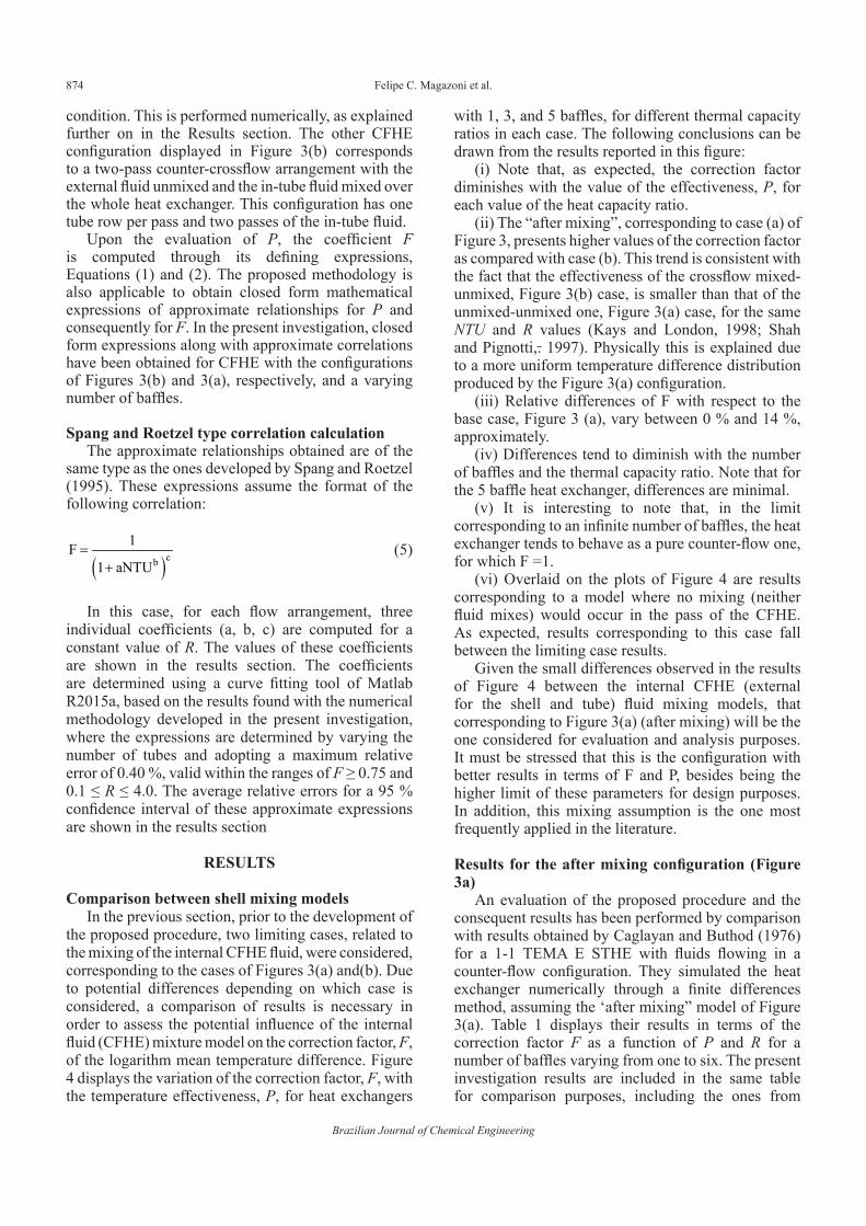
with 1, 3, and 5 baffles, for different thermal capacity ratios in each case. The following conclusions can be drawn from the results reported in this figure:
(i) Note that, as expected, the correction factor diminishes with the value of the effectiveness, P, for each value of the heat capacity ratio.
(ii) The “after mixing”, corresponding to case (a) of Figure 3, presents higher values of the correction factor as compared with case (b). This trend is consistent with the fact that the effectiveness of the crossflow mixed-unmixed, Figure 3(b) case, is smaller than that of the unmixed-unmixed one, Figure 3(a) case, for the same NTU and R values (Kays and London, 1998; Shah and Pignotti,. 1997). Physically this is explained due to a more uniform temperature difference distribution produced by the Figure 3(a) configuration.
(iii) Relative differences of F with respect to the base case, Figure 3 (a), vary between 0 % and 14 %, approximately.
(iv) Differences tend to diminish with the number of baffles and the thermal capacity ratio. Note that for the 5 baffle heat exchanger, differences are minimal.
(v) It is interesting to note that, in the limit corresponding to an infinite number of baffles, the heat exchanger tends to behave as a pure counter-flow one, for which F =1.
(vi) Overlaid on the plots of Figure 4 are results corresponding to a model where no mixing (neither fluid mixes) would occur in the pass of the CFHE. As expected, results corresponding to this case fall between the limiting case results.
Given the small differences observed in the results of Figure 4 between the internal CFHE (external for the shell and tube) fluid mixing models, that corresponding to Figure 3(a) (after mixing) will be the one considered for evaluation and analysis purposes. It must be stressed that this is the configuration with better results in terms of F and P, besides being the higher limit of these parameters for design purposes. In addition, this mixing assumption is the one most frequently applied in the literature.
Results for the after mixing configuration (Figure 3a)
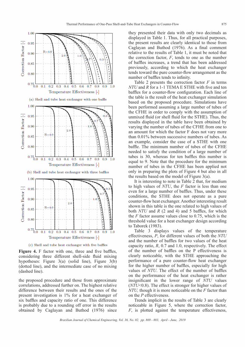
An evaluation of the proposed procedure and the consequent results has been performed by comparison with results obtained by Caglayan and Buthod (1976) for a 1-1 TEMA E STHE with fluids flowing in a counter-flow configuration. They simulated the heat exchanger numerically through a finite differences method, assuming the ‘after mixing” model of Figure 3(a). Table 1 displays their results in terms of the correction factor F as a function of P and R for a number of baffles varying from one to six. The present investigation results are included in the same table for comparison purposes, including the ones from
( )cb
1F1 aNTU
=+
In this case, for each flow arrangement, three individual coefficients (a, b, c) are computed for a constant value of R. The values of these coefficients are shown in the results section. The coefficients are determined using a curve fitting tool of Matlab R2015a, based on the results found with the numerical methodology developed in the present investigation, where the expressions are determined by varying the number of tubes and adopting a maximum relative error of 0.40 %, valid within the ranges of F ≥ 0.75 and 0.1 ≤ R ≤ 4.0. The average relative errors for a 95 % confidence interval of these approximate expressions are shown in the results section
RESULTS
Comparison between shell mixing modelsIn the previous section, prior to the development of
the proposed procedure, two limiting cases, related to the mixing of the internal CFHE fluid, were considered, corresponding to the cases of Figures 3(a) and(b). Due to potential differences depending on which case is considered, a comparison of results is necessary in order to assess the potential influence of the internal fluid (CFHE) mixture model on the correction factor, F, of the logarithm mean temperature difference. Figure 4 displays the variation of the correction factor, F, with the temperature effectiveness, P, for heat exchangers
(5)
Thermal Performance of One-Pass Shell-and-Tube Heat Exchangers in Counter-Flow
Brazilian Journal of Chemical Engineering, Vol. 36, No. 02, pp. 869 - 883, April - June, 2019
875
they presented their data with only two decimals as displayed in Table 1. Thus, for all practical purposes, the present results are clearly identical to those from Caglayan and Buthod (1976). As a final comment relative to the results of Table 1, it must be noted that the correction factor, F, tends to one as the number of baffles increases, a trend that has been addressed previously, according to which the heat exchanger tends toward the pure counter-flow arrangement as the number of baffles tends to infinity.
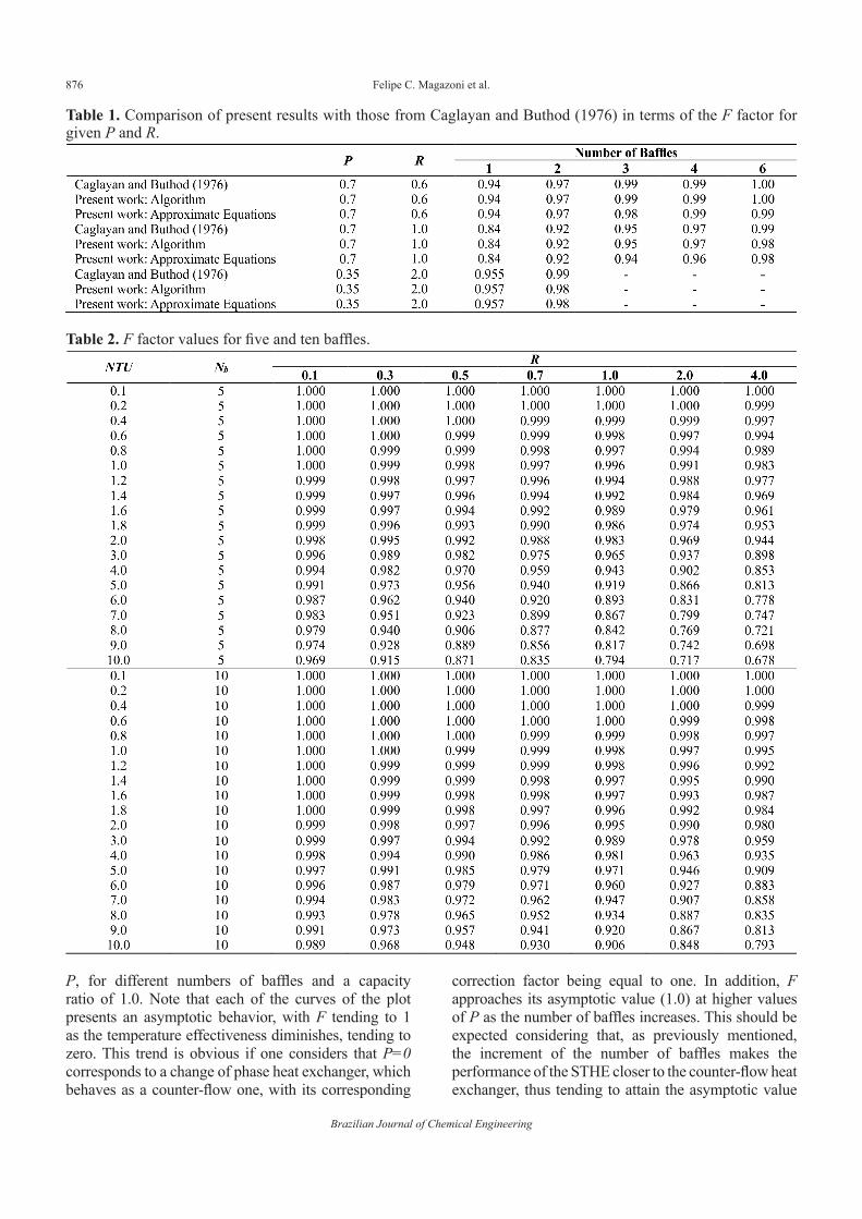
Table 2 presents the correction factor F in terms NTU and R for a 1-1 TEMA E STHE with five and ten baffles for a counter-flow configuration. Each line of the table is the result of the heat exchanger simulation based on the proposed procedure. Simulations have been performed assuming a large number of tubes of the CFHE in order to comply with the assumption of unmixed fluid (or shell fluid for the STHE). Thus, the results displayed in the table have been obtained by varying the number of tubes of the CFHE from one to an amount for which the factor F does not vary more than 0.01% between successive numbers of tubes. As an example, consider the case of a STHE with one baffle. The minimum number of tubes of the CFHE needed to satisfy the condition of a large number of tubes is 30, whereas for ten baffles this number is equal to 9. Note that the procedure for the minimum number of tubes in the CFHE has been applied not only in preparing the plots of Figure 4 but also in all the results based on the model of Figure 3(a).
It is interesting to note in Table 2 that, for medium to high values of NTU, the F factor is less than one even for a large number of baffles. Thus, under these conditions, the STHE does not operate as a pure counter-flow heat exchanger. Another interesting result shown in this table is the one related to high values of both NTU and R (2 and 4) and 5 baffles, for which the F factor assume values close to 0.75, which is the threshold value for a heat exchanger design according to Taborek (1983).
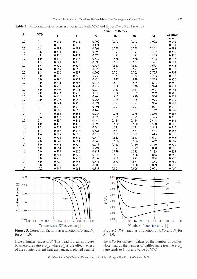
Table 3 displays values of the temperature effectiveness, P, for different values of both the NTU and the number of baffles for two values of the heat capacity ratio, R, 0.7 and 1.0, respectively. The effect of the number of baffles on the P effectiveness is clearly noticeable, with the STHE approaching the performance of a pure counter-flow heat exchanger for the higher number of baffles, especially for high values of NTU. The effect of the number of baffles on the performance of the heat exchanger is rather insignificant in the lower range of NTU values (NTU<0.8). The effect is stronger for higher values of NTU, though it is more noticeable on the F factor than on the P effectiveness.
Trends implicit in the results of Table 3 are clearly noticeable in Figure 5, where the correction factor, F, is plotted against the temperature effectiveness,
Figure 4. F factor with one, three and five baffles, considering three different shell-side fluid mixing hypotheses: Figure 3(a) (solid line), Figure 3(b) (dotted line), and the intermediate case of no mixing (dashed line).
the proposed procedure and those from approximate correlations, addressed further on. The highest relative difference between their results and the ones of the present investigation is 1% for a heat exchanger of six baffles and capacity ratio of one. This difference is probably due to a rounding off error in the results obtained by Caglayan and Buthod (1976) since
Felipe C. Magazoni et al.
Brazilian Journal of Chemical Engineering
876
Table 1. Comparison of present results with those from Caglayan and Buthod (1976) in terms of the F factor for given P and R.
Table 2. F factor values for five and ten baffles.
P, for different numbers of baffles and a capacity ratio of 1.0. Note that each of the curves of the plot presents an asymptotic behavior, with F tending to 1 as the temperature effectiveness diminishes, tending to zero. This trend is obvious if one considers that P=0 corresponds to a change of phase heat exchanger, which behaves as a counter-flow one, with its corresponding
correction factor being equal to one. In addition, F approaches its asymptotic value (1.0) at higher values of P as the number of baffles increases. This should be expected considering that, as previously mentioned, the increment of the number of baffles makes the performance of the STHE closer to the counter-flow heat exchanger, thus tending to attain the asymptotic value
Thermal Performance of One-Pass Shell-and-Tube Heat Exchangers in Counter-Flow
Brazilian Journal of Chemical Engineering, Vol. 36, No. 02, pp. 869 - 883, April - June, 2019
877
Table 3. Temperature effectiveness P variation with NTU and Nb for R = 0.7 and R = 1.0.
Figure 5. Correction factor F as a function of P and Nb for R = 1.0.
Figure 6. P/Pcc ratio as a function of NTU and Nb for R = 1.0.
(1.0) at higher values of P. This trend is clear in Figure 6, where the ratio P/Pcc, where Pcc is the effectiveness of the counter-current heat exchanger, is plotted against
the NTU for different values of the number of baffles. Note that, as the number of baffles increases the P/Pcc ratio tends to 1, for any value of NTU.
Felipe C. Magazoni et al.
Brazilian Journal of Chemical Engineering
878
Table 4. F factor as a function of Nb, P and R.
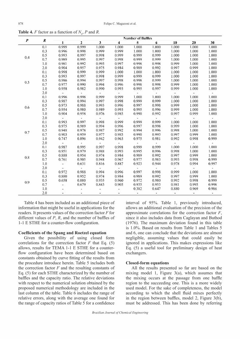
Table 4 has been included as an additional piece of information that might be useful in applications for the readers. It presents values of the correction factor F for different values of P, R, and the number of baffles of 1-1 E STHE for a counter-flow configuration.
Coefficients of the Spang and Roetzel equationGiven the possibility of using closed form
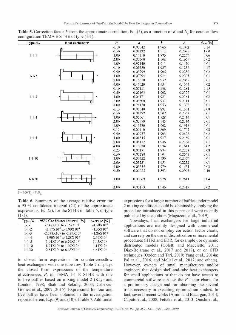
correlations for the correction factor F that Eq. (5) allows, results for TEMA 1-1 E STHE for a counter-flow configuration have been determined based on constants obtained by curve fitting of the results from the procedure introduce herein. Table 5 includes both the correction factor F and the resulting constants of Eq. (5) for each STHE characterized by the number of baffles and the capacity ratio. The relative deviations with respect to the numerical solution obtained by the proposed numerical methodology are included in the last column of the table. Table 6 includes the range of relative errors, along with the average one found for the range of capacity ratios of Table 5 for a confidence
interval of 95%. Table 1, previously introduced, allows an additional evaluation of the precision of the approximate correlations for the correction factor F, since it also includes data from Caglayan and Buthod (1976). The maximum deviation found in this table is 1.0%. Based on results from Table 1 and Tables 5 and 6, one can conclude that the deviations are almost negligible, assuming values that could easily be ignored in applications. This makes expressions like Eq. (5) a useful tool for preliminary design of heat exchangers.
Closed-form equationsAll the results presented so far are based on the
mixing model 1, Figure 3(a), which assumes that the mixing occurs at the passage from one baffle region to the succeeding one. This is a more widely used model. For the sake of completeness, the model according to which the shell fluid mixes perfectly in the region between baffles, model 2, Figure 3(b), must be addressed. This has been done by referring
Thermal Performance of One-Pass Shell-and-Tube Heat Exchangers in Counter-Flow
Brazilian Journal of Chemical Engineering, Vol. 36, No. 02, pp. 869 - 883, April - June, 2019
879
Table 5. Correction factor F from the approximate correlation, Eq. (5), as a function of R and Nb for counter-flow configuration TEMA E STHE of type (1-1).
d = 100(Fth - F)/Fth
Table 6. Summary of the average relative error for a 95 % confidence interval (CI) of the approximate expressions, Eq. (5), for the STHE of Table 5, of type (1-1).
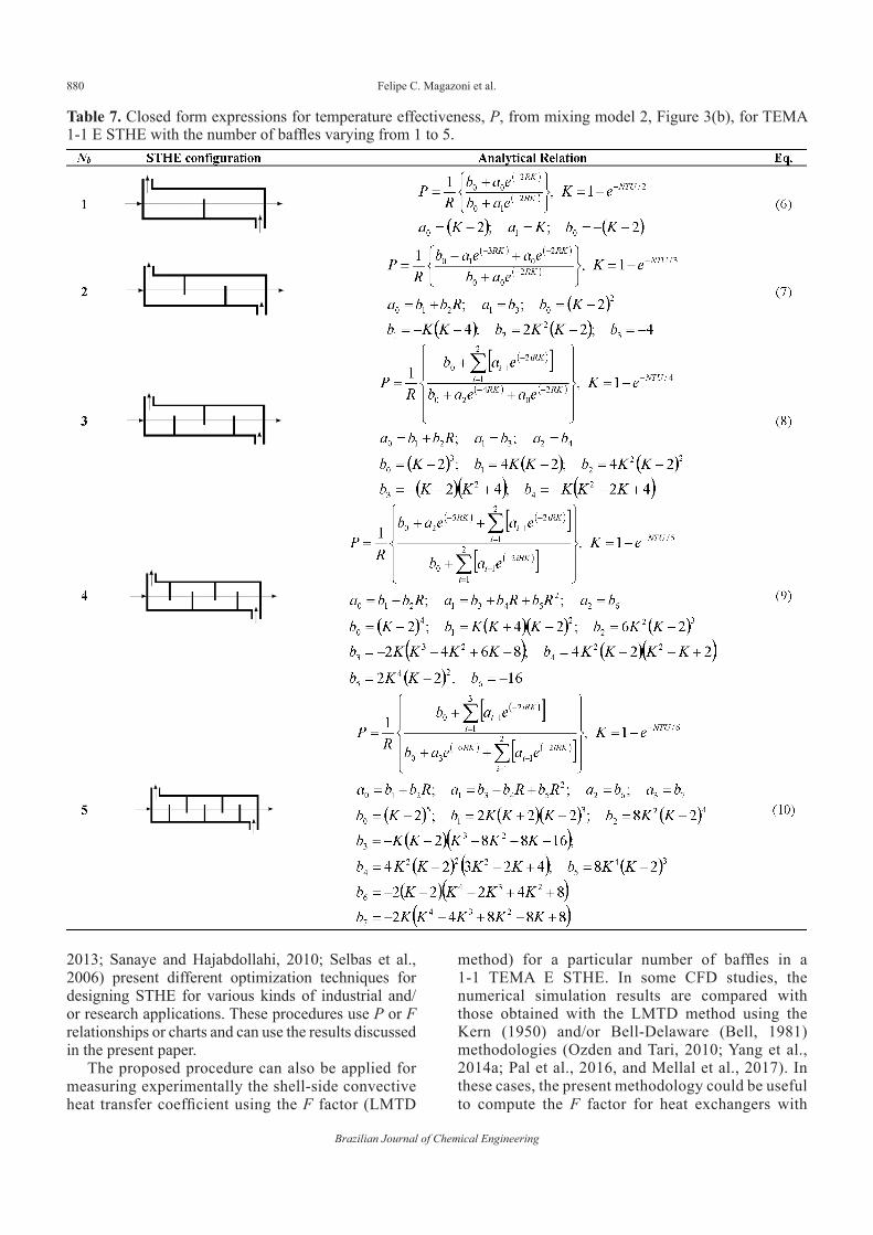
to closed form expressions for counter-crossflow heat exchangers with one tube row. Table 7 displays the closed form expressions of the temperature effectiveness, P, of TEMA 1-1 E STHE with one to five baffles based on mixing model 2 (Kays and London, 1998; Shah and Sekuliç, 2003; Cabezas-Gómez et al., 2007, 2015). Expressions for four and five baffles have been obtained in the investigation reported herein, Eqs. (9) and (10) of Table 7. Additional
expressions for a larger number of baffles under model 2 mixing conditions could be obtained by applying the procedure introduced in this paper and were recently published by the authors (Magazoni et al., 2019).
Nowadays, heat exchangers for large industrial applications are mainly designed with commercial software that do not employ correction factor charts, and can rely on the use of discretization or incremental procedures (HTRI and EDR, for example), or dynamic distributed models (Coletti and Maccietto, 2011; Diaz-Bejarano et al., 2017 and 2018), or on CFD techniques (Ozden and Tari, 2010; Yang et al., 2014a; Pal et al., 2016, and Mellal et al., 2017; and others). However, owners of small manufactures and/or engineers that design shell-and-tube heat exchangers for small applications or that do not have access to commercial software can use the F factor charts for a preliminary design and for obtaining the several trials necessary in executing optimization studies. In fact, several recent works (Amini and Bazargan, 2014; Caputo et al., 2008; Fettaka et al., 2013; Onishi et al.,
Felipe C. Magazoni et al.
Brazilian Journal of Chemical Engineering
880
Table 7. Closed form expressions for temperature effectiveness, P, from mixing model 2, Figure 3(b), for TEMA 1-1 E STHE with the number of baffles varying from 1 to 5.
2013; Sanaye and Hajabdollahi, 2010; Selbas et al., 2006) present different optimization techniques for designing STHE for various kinds of industrial and/or research applications. These procedures use P or F relationships or charts and can use the results discussed in the present paper.
The proposed procedure can also be applied for measuring experimentally the shell-side convective heat transfer coefficient using the F factor (LMTD
method) for a particular number of baffles in a 1-1 TEMA E STHE. In some CFD studies, the numerical simulation results are compared with those obtained with the LMTD method using the Kern (1950) and/or Bell-Delaware (Bell, 1981) methodologies (Ozden and Tari, 2010; Yang et al., 2014a; Pal et al., 2016, and Mellal et al., 2017). In these cases, the present methodology could be useful to compute the F factor for heat exchangers with
Thermal Performance of One-Pass Shell-and-Tube Heat Exchangers in Counter-Flow
Brazilian Journal of Chemical Engineering, Vol. 36, No. 02, pp. 869 - 883, April - June, 2019
881
few baffles. According to Das and Bhojak (2016), several heat exchanger types, i.e., shell-and-tube, plate-fin, and radiators, are used in plastic injection molding machines to cool the refrigeration fluid, which is commonly industrial oil. Some of these systems use small STHE with three baffles for the oil refrigeration with cool water. In these particular cases the present methodology can be used for the preliminary design and/or for checking the chosen heat exchanger dimensions.
CONCLUSIONS
A computational methodology was applied in the study reported herein to determine the temperature effectiveness, P, and the LMTD correction factor, F, for STHE with arbitrary number of baffles for two different mixing models of shell-side fluid. The reported study focused on TEMA E STHE with one-pass of fluids flowing in counter-flow. Results confirmed that the mixing condition of Figure 3(a) is the one that leads to the highest P and F values. The numerical results obtained for this configuration were validated through the comparison of F factors with data numerically obtained by Caglayan and Buthod (1976), presenting very small (almost zero) relative errors (Table 1) for most of the numbers of baffles and capacity values used in the comparisons.
In order to systematize the simulation results obtained, the developed methodology was used to obtain approximate expressions, Equation (5), for computing the F factor as a function of Nb for the Figure 3(a) mixing hypothesis. In addition, closed form expressions for P (and consequently for F) were obtained as a function of the number of baffles for the mixing model of Figure 3(b), see Table 7. These expressions are very appropriate for either a first trial or preliminary computerized analysis or design purposes, making the computation of both P and F easier.
Finally, as an important contribution, the present study allowed the determination of new temperature effectiveness and correction factor values for different numbers of baffles of 1-1 TEMA E shell-and-tube heat exchangers.
ACKNOWLEDGMENTS
The authors fully acknowledge the support provided by the Conselho Nacional de Desenvolvimento e Tecnológico (CNPq - Processes 306675/2014-5 and 304972/2017-7) and also from Fundação de Amparo à Pesquisa do Estado de São Paulo (FAPESP - Process 2016/09509-1).
The authors also thank the important contributions of the reviewers.
NOMENCLATURE
a [-] Coefficient defined in Table 5, see Eq. (5)a0 - a3 Coefficients defined in Table 7A [m2] Heat transfer total surface areab [-] Coefficient defined in Table 5, see Eq. (5)b0 - b7 Coefficients defined in Table 7c [-] Coefficient defined in Table 5, see Eq. (5)C [W/K] Heat capacityF [-] LMTD correction factorK Coefficient defined in Table 7i Dummy index used in Table 7n [-] Number of shell-side fluid passesNb [-] Number of baffles,NTU [-] Number of transfer unitsP [-] Heat exchanger temperature effectivenessQ [W] Heat transfer rateR [-] Heat capacity ratioT [K] Temperature U [W/(m2K)] Overall heat transfer coefficient
Special charactersχ [-] Parameter defined by Eq. (2)δ [\%] Relative error defined in Table 5
Subscriptsb Bafflec Coldcc Counter-flowh Hotin Inletmax Maximummin Minimumout Outletth Theoretical
AbbreviationsCFD Computational Fluid DynamicsCFHE Crossflow Heat ExchangerEDR Heat Design and RatingHTRI Heat Transfer Research, IncLMTD Logarithmic Mean Temperature DifferenceTEMA Tubular Exchanger Manufacturers AssociationSTHE Shell-and-tube Heat Exchanger
REFERENCES
Amini, M., Bazargan, M. Two objective optimization in shell-and-tube heat exchangers using genetic algorithm. Applied Thermal Engineering, 69, 278-285 (2014). https://doi.org/10.1016/j.applthermaleng.2013.11.034
Felipe C. Magazoni et al.
Brazilian Journal of Chemical Engineering
882
Bell, K.J. Delaware method for shell side design. In: Kakac, S., Bergles, A.E., Mayinger, F. (Eds), Heat exchangers: thermal-hydraulic fundamentals and design. Hemisphere Publishing Corp., New York, 581-618, 1981.
Bowman, R.A. Mean temperature difference correction in multipass exchangers, Industrial & Engineering Chemistry, 28, 541-544 (1936). https://doi.org/10.1021/ie50317a009
Bowman, R.A., Mueller, A.C., Nagle, W.M. Mean temperature difference in design, Transactions ASME, 62, 283-293 (1940).
Cabezas-Gómez, L., Navarro, H.A., Saiz-Jabardo, J.M. Thermal Performance Modeling of Cross-Flow Heat Exchangers. Springer, London (2015). https://doi.org/10.1007/978-3-319-09671-1
Cabezas-Gómez, L., Navarro, H.A., Saiz-Jabardo, J.M. Thermal performance of multipass parallel and counter-cross-flow heat exchangers, ASME Journal of Heat Transfer, 129, 282-290 (2007). https://doi.org/10.1115/1.2430719
Caglayan, A.N., Buthod, P. Factors correct air-cooler and S and T exchangers LMTD, Oil and Gas Journal, 6, 91-94 (1976).
Caputo, A.C., Pelagagge, P.M., Salini, P. Heat exchanger design based on economic optimization, Applied Thermal Engineering, 10, 1151-1159 (2008). https://doi.org/10.1016/j.applthermaleng.2007.08.010
Chen, F., Cai, J., Li, X., Wang, L.Y. 3D numerical simulation of fluid-solid coupled heat transfer with variable property in a LBE-helium heat exchanger, Nuclear Engineering and Design, 274, 66-76 (2014). https://doi.org/10.1016/j.nucengdes.2014.04.024
Coletti, F., Macchieto, S. A Dynamic, Distributed Model of Shell-and-Tube Heat Exchangers Undergoing Crude Oil Fouling Industrial and Engineering Chemistry Research, AIChE Journal, 50, 4515-4533 (2011). https://doi.org/10.1021/ie901991g
Das, S.K., Bhojak, K. Oil cooler selection for hydraulic system of plastic injection moulding machine: a review, International Journal of Science and Research, 5, 2266-2271 (2016). https://doi.org/10.21275/v5i4.NOV163211
Diaz-Bejarano, E., Coletti, F., Macchieto, S. Modeling and prediction of shell-side fouling in shell-and-tube heat exchangers, Heat Transfer Engineering, 40, 845-861 (2018). https://doi.org/10.1080/01457632.2018.1446814
Diaz-Bejarano, E., Coletti, F., Macchieto, S. Thermo-Hydraulic analysis of refinery heat exchangers undergoing fouling, AIChE Journal, 63, 984-1001 (2017). https://doi.org/10.1002/aic.15457
Domingos, J.D. Analysis of complex assemblies of heat exchangers, International Journal of Heat and Mass Transfer, 12, 537-548 (1969). https://doi.org/10.1016/0017-9310(69)90037-4
Fettaka, S., Thibault, J., Gupta, Y.P. Design of shell-and-tube heat exchangers using multi-objective optimization, International Journal of Heat and Mass Transfer, 60, 343-354 (2013). https://doi.org/10.1016/j.ijheatmasstransfer.2012.12.047
Fischer, F.K. Mean temperature difference correction in multipass exchangers, Industrial & Engineering Chemistry, 30, 377-383 (1938). https://doi.org/10.1021/ie50340a004
Gardner, K.A. and Taborek, J., Mean temperature difference: A reappraisal, American Institute of Chemical Engineers Journal, 23, 777-786 (1977). https://doi.org/10.1002/aic.690230602
Gardner, K.A. Mean temperature difference in multipass exchangers: correction factors with shell fluid unmixed, Industrial & Engineering Chemistry, 33, 1495-1500 (1941). https://doi.org/10.1021/ie50384a006
Hess, L.E. The effectiveness of heat exchangers with one shell pass and five tube passes. Ph.D. thesis, Naval Postgraduate School, Monterey (1986).
Kays, W.M., London, A.L. Compact Heat Exchangers. 3rd Edition, McGraw Hill, New York (1988).
Kern, D.Q. Process heat transfer. McGraw-Hill, New York, 1950.
Kraus, A.D., Kern, D.G. The effectiveness of heat exchangers with one shell pass and even number of tube passes, ASME paper 65-HT-18 (1965).
Leoni, G.B., Klein, T.S., Medronho, R.A. Assessment with computational fluid dynamics of the effects of baffle clearances on the shell side flow in a shell and tube heat exchanger, Applied Thermal Engineering, 112, 497-506 (2017). https://doi.org/10.1016/j.applthermaleng.2016.10.097
Magazoni, F., Cabezas-Gómez, L. Numerical Methodologies for Computing Effectiveness of Crossflow Heat Exchangers with Multiple Pass and Mixture Conditions of Both Fluids Heat Exchangers: Characteristics, Chapter 4, In: Types and Emerging Applications, 1st Edition, Energy Science, Engineering and Technology, Nova Science Publishers, New York (2016).
Magazoni, F., Cabezas-Gómez, L., Alvariño, P.F., Saiz-Jabardo, J.M. Closed form relationships of temperature effectiveness of cross-flow heat exchangers, Thermal Sciences and Engineering Progress, 9, 110-120 (2019). https://doi.org/10.1016/j.tsep.2018.11.005
Mellal, M., Benzeguir, R., Sahel, D., Ameur, H. Hydro-thermal shell-side performance evaluation of a shell and tube heat excganger under different baffle arrangement and orientation, International Journal of Thermal Sciences, 121, 138-149 (2017). https://doi.org/10.1016/j.ijthermalsci.2017.07.011
Nagle, W.M. Mean temperature differences in multipass heat exchangers, Industrial & Engineering Chemistry, 25, 604-609 (1933). https://doi.org/10.1021/ie50282a003
Thermal Performance of One-Pass Shell-and-Tube Heat Exchangers in Counter-Flow
Brazilian Journal of Chemical Engineering, Vol. 36, No. 02, pp. 869 - 883, April - June, 2019
883
Navarro, H.A., Cabezas-Gómez, L. A new approach for thermal performance calculation of cross-flow heat exchangers, International Journal of Heat and Mass Transfer, 48, 3880-3888 (2005). https://doi.org/10.1016/j.ijheatmasstransfer.2005.03.027
Onishi, V., Ravagnani, M.A., Caballero, J.A. Mathematical programming model for heat exchanger design through optimization of partial objectives, Energy Conversion and Management, 74, 60-69 (2013). https://doi.org/10.1016/j.enconman.2013.05.011
Ozden, E., Tari, I. Shell side CFD analysis of a small shell-and-tube heat exchanger, Energy Conversion and Management, 51, 1004-1014 (2010). https://doi.org/10.1016/j.enconman.2009.12.003
Pal, E., Kumar, I., Joshi, J.B., Maheshwari, N.K. CFD simulations of shell-flow side in a shell-and-tube type heat exchanger with and without baffles, International Chemical Engineering Science, 143, 314-340 (2016). https://doi.org/10.1016/j.ces.2016.01.011
Pignotti, A., Cordero, G.O. Mean temperature difference in multipass crossflow, ASME Journal of Heat Transfer, 105, 584-591 (1983). https://doi.org/10.1115/1.3245625
Pignotti, A., Tamborenea, P.I. Thermal effectiveness of multiple shell and tube pass TEMA E heat exchangers, ASME Journal of Heat Transfer, 110, 54-59 (1988). https://doi.org/10.1115/1.3250472
Pignotti, A. Effectiveness of series assemblies of divided-flow heat exchangers, ASME Journal of Heat Transfer, 108, 141-146 (1986). https://doi.org/10.1115/1.3246878
Roetzel, W., Spang, B. Fundamentals of heat exchanger design - Thermal design of heat exchangers - Chapter C1. In: VDI-GVC (Ed.), VDI Heat Atlas, 2nd Edition, Springer-Verlag Berlin Heidelberg, Dusseldorf, Germany, 33-66, 2010. https://doi.org/10.1007/978-3-540-77877-6_4
Roetzel, W., Lee, D.W. Effect of baffle/shell leakage flow on heat transfer in shell-and-tube heat exchangers, Experimental Thermal and Fluid Science, 8, 10-20 (1994). https://doi.org/10.1016/0894-1777(94)90068-X
Sanaye, S., Hajabdollahi, H. Multi-objective optimization of shell and tube heat exchangers, Applied Thermal Engineering, 30, 1937-1945 (2010). https://doi.org/10.1016/j.applthermaleng.2010.04.018
Sekuliç, D.P., Shah, R.K., Pignotti, A. A review of solution methods for determining effectiveness-ntu relationships for heat exchangers with complex flow arrangements, Applied Mechanics Reviews, 52, 97-117 (1999). https://doi.org/10.1115/1.3098928
Selbas, R., Kizilkan, O., Reppich, M. A new design approach for shell-and-tube heat exchangers using algorithms from economic point of view, Chemical Engineering and Processing: Process Intensification 45, 268-275 (2006). https://doi.org/10.1016/j.cep.2005.07.004
Shah, R.K., Pignotti, A. Influence of a finite number of baffles on shell-and-tube heat exchanger performance, Heat Transfer Engineering 18, 82-94 (1997). https://doi.org/10.1080/01457639708939891
Shah, R.K., Sekuliç, D.P. Fundamentals of Heat Exchanger Design. John Wiley & Sons, Inc., New Jersey (2003). https://doi.org/10.1002/9780470172605
Spang, B., Roetzel, W. Neue Näherungsgleichung zur einheitlichen Berechnung von Wärmeübertragern, Heat and Mass Transfer, 30, 417-422 (1995). https://doi.org/10.1007/BF01647446
Taborek, J. Charts for mean temperature difference in industrial heat exchanger configuration, in: Schlünder, E.U. (Editor-inChief), Heat Exchanger Design Handbook, Hemisphere Publishing Corporation, New York, 1.5.3-8, 1983.
Underwood, A.J.V. The calculation of the mean temperature difference in multipass heat exchangers, Institute of Petroleum Technologists, 20, 145-158 (1934).
Wang, X., Zheng, N., Liu, Z., Liu, W. Numerical analysis and optimization study on shell-side performances of a shell and tube heat exchanger with staggered baffles, International Journal of Heat and Mass Transfer, 124, 247-259 (2018). https://doi.org/10.1016/j.ijheatmasstransfer.2018.03.081
Yang, J., Ma, L., Bock, J., Jacobi, A.M., Lie, W. A comparison of four numerical modeling approaches for enhanced shell-and-tube exchangers with experimental validation, Applied Thermal Engineering, 65, 369-383 (2014a). https://doi.org/10.1016/j.applthermaleng.2014.01.035
Yang, J.F., Zeng, M., Wang, Q.W. Effects of sealing strips on shell-side flow and heat transfer performance of a heat exchanger with helical baffles, Applied Thermal Engineering, 64, 117-128 (2014b). https://doi.org/10.1016/j.applthermaleng.2013.11.064