Embed Size (px)
Citation preview
THERMAL PERFORMANCE ANALYSIS OF HELICAL COIL SOLAR CAVITY
RECEIVER BASED PARABOLIC TROUGH CONCENTRATOR
Arun Kumar and S.K.Shukla*
Centre for Energy and Resources Development, Department of Mechanical Engineering,Indian
Institute of Technology (Banaras Hindu University), Varanasi-221005, India
*Corresponding author; E-mail: [email protected]
The present paper investigates the performance of helical coil solar cavity
receiver based parabolic trough concentrator (PTC) for the conversion of
energy received from the sun into useful heat and finally electricity. The
experimental setup has been designed in such a way that it enhances heat
transfer coefficient and reduces losses in the PTC. The PTC comprised of a
blackened helical coil made up of two concentric borosilicate glass cylinder
with vacuum in the annulus, which is kept at a focal line of PTC. The
vacuum significantly reduces the losses which are evident from a relatively
higher temperature of a 565K obtained at the surface of the helical coil.Heat
loss from helical coil solar cavity receiver has also been investigated and it
was found that with the increase in vacuum pressure at annulus by 50%, the
losses from the receiver has been increased by 26.67%. The heat loss from
receiver has been observed to be proportional to the vacuum pressure within
the annulus space.
Keywords: “Helically coiled tube”, “double glazing surface”, “heat
collecting element”, “vacuum tube outer cell”.
1. Introduction
The application of solar energy is one of the best ways to face global challenges as the climate
change. In order to supply more and more thermal output, solar energy is often used in power
plants[1]. Among all the concentrated solar power technology, parabolic trough concentrator is the
most advanced technology for power generation[2]. A parabolic trough concentrator is a line focusing
solar collector that is straight in one dimension and curved as a parabolic shape in the other two
dimensions. It is lined with mirror film of high reflectivity[3–6]. Solar radiation, which enters the PTC
parallel to the plane of symmetry, is concentrated along the focal line, where a tube receiver is
installed to receive the concentrated solar radiation[7,8]. The receiver is the heart of concentrated solar
power (CSP) system. And so, Many researchers pay attention towards the design of a variety of solar
receivers so that the thermal performance of CSP system can be improved. Evangelos Bellos et al[9]
use internal fins, attached longitudinally with the inner surface of receiver pipe of the parabolic trough
collector. The examined parameters for the analysis of the internally finned type solar receiver are the
thermal enhancement index, the thermal efficiency, the pressure losses and the Nusselt number. They
determined the optimum value of length and thickness of fins for the optimum thermal performance of
PTC system. E. Bellos et al[10].studies the influence of receiver geometry on the collection efficiency
of absorber tube. They designed the absorber pipe in such a way that the inner surface of the tube
becomes a converging-diverging type. The sinusoidal variation of diameter along the length of
receiver tube increases the inner heat transfer area for the heat transfer fluid together with it changes
the flow regime from laminar to turbulent flow. They found that the increase in efficiency by
4.55%.The absorber with pin fin arrays inserting, presented by Gong Xiangtao et al[11]is more
efficient than the simple horizontal tube receiver of a parabolic trough concentrator. Their model
improves the overall heat transfer coefficient by 12%. The convective heat transfer coefficient can also
be increased by inserting the twisted tape insert at the inner surface of the receiver tube. The presence
of twisted tap is responsible for the rotation of flow in the axial direction thereby modifying the
Reynolds and the Nusselt numbers[12].A Mwesigye et al.[13] investigates a thermal and
thermodynamic performance of a receiver tube with perforated plate inserts for a parabolic trough
solar collector and found the maximum thermal efficiency improvement as compared to smooth
receiver in turbulent flow regime is 8%.
The solar receiver tube is generally surrounded by a glass tube to block infrared radiations and
to reduce convective losses. Typically, the solar thermal power plants based on parabolic trough
concentrator use evacuated space between the absorber tube and the glass tube to reduce heat losses
and to increase thermal efficiency. Vacuum creation between receiver tube and the environment is
fundamental to reduce heat loss in solar thermal application[14]. The vacuum and its lifespan will
greatly affect the heat loss in a receiver[15]. Vacuum tube should be designed in such a way that there
should not be any kind of vacuum loss i.e. working on vacuum leakage is also important. Li et al. [16]
Analyses the different type reasons for vacuum loss in the annulus of the solar receiver. They
concluded that the accumulation and infiltration of hydrogen are the main reasons for heat losses.
Therefore, removal of hydrogen from the annulus space is essential. Although it is impossible to
remove 100% hydrogen from the annulus space, maximum amount can be reduced by the process of
degassing and usage of getters in the receiver. Liu J et al.[17]developed a receiver with borosilicate
glass to metal seal. They claimed that it reduces the vacuum loss and hence the reduction of loss from
the receiver thereby increasing the efficiency of the PTC system. Zhang et al.[18]experimentally
investigated the effects of wind, vacuum glass tube, radiation, and structural characteristics of the heat
losses. They concluded that the thermal efficiencies of the receiver were found to be 0.791 and 0.472
in calm and windy days, respectively, at a test temperature of about 100oC.
After going through the various literature, it would be no exaggeration to say that the huge
research has been done on the design and performance of the solar receiver. Most of the solar receivers
of a parabolic trough concentrator are a horizontal tube or the tube with different inner surface
geometry like internal fins, converging-diverging sinusoidal geometry, fin pin arrays, perforated
plates, twisted tape inserts. But nobody has used the receiver of helical coil geometry for the
improvement of performance of parabolic trough collector. This paper presents the design and
performance of a novel receiver concept presented using thermal oil as heat transfer fluid for parabolic
trough concentrators. The objective of the present study was to propose a double glazing helical coil
solar cavity receiver with the vacuum tube outer cell to minimize losses and thereby enhancing the
thermal efficiency of a parabolic trough concentrator.
2. Experimental procedure
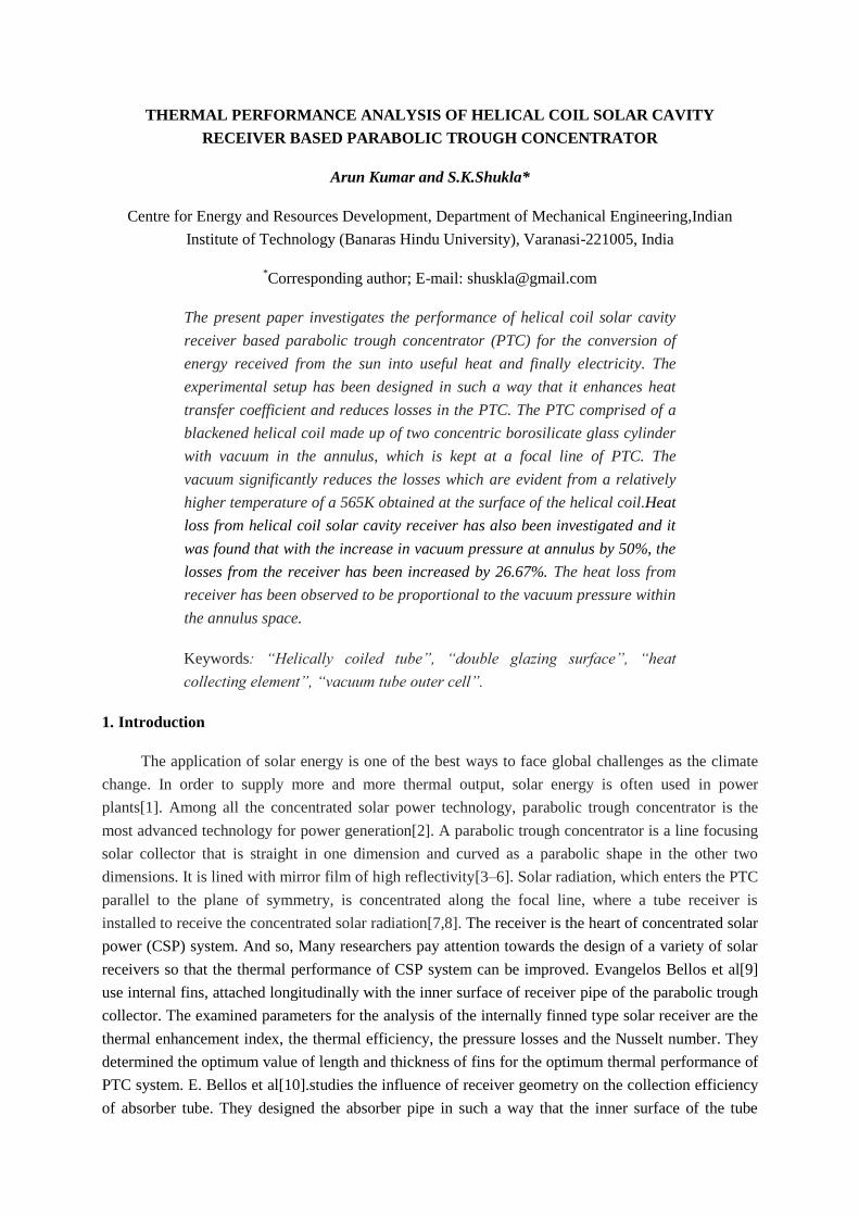
Fig. 1 shows the photograph of experimental setup installed at the rooftop of CERD, Mechanical
Engineering Department, IIT (BHU), Varanasi. The heart of the experimental setup is a line
concentrating helical coil solar cavity receiver. Double glazing helical coil solar cavity receiver is kept
at the focus of PTC with a focal length of 0.606m in order to ensure that the receiver is completely
inside the cylindrical intense image formed by reflected sunlight from the aperture of parabolic trough
concentrator. The experimental setup consists of a 0.5 HP centrifugal pump ensuring the thermal oil
circulation through the helical coil solar cavity receiver. The circulated oil in the receiver is supplied
from oil tank of 10-liter capacity. The flow rate of oil entering the receiver is measured by a
flowmeter. The thermal oil gets heated while flowing through the well-focused receiver and exchange
this heat to water in hot water tank of capacity 46 liters. The hot water tank is a shell and coil type heat
exchanger where the oil is circulated through the coil dipped in water in the water tank. The inlet and
outlet temperatures of oil are measured by thermocouple sensors which transmit the signals to a data
logging facility connected to the present setup. A sun tracker continuously tracks the sun and as a
result, the cycle can run efficiently. The tracker tracks the sun on an hourly basis by rotating the PTC
at a 15° angle per hour. It should be noted that the system operates in a closed cycle and the effect of
all the environmental parameters such as wind speed, wind direction, relative humidity, air
temperature, dust/dirt and solar radiation are taken into account.Helical coil receiver has been enclosed
with two concentric borosilicate glass covers with vacuum at the outer annulus as shown in the Fig.1.
Parallel rays of solar radiation incident on the aperture and concentrated at the focus where the
receiver is placed. The main function of the receiver is to convert solar energy into thermal energy in
terms of heated oil. In the present experimental setup, the performance of evacuated tube helical coil
solar cavity receiver has been analyzed and compared with the empty tube receiver.
In the present linear concentrating parabolic trough collector, the concentration ratio is
20.31.Further; the data on experimental setup are collected on different days daily from January to
June 2017. However, some of the collected data around the days have been used for performance
analysis.
Table 1. Specification of experimental set up
Experimental set up parts Dimensions
Length of helical coil 5.172 m
Perimeter of copper tube 0.02188 m
Receiver Area 0.113716 m
Parametric length of receiver 1.8432 m
Width of collector 1.220 m
Aperture Area 2.2487 m
Concentration Ratio 19.77 m
Diameter of Helical circle(D) 25 mm
Diameter of Cu Tube(d) 5 mm
Thickness of Cu Tube(t) 1 mm
Pitch of Helical coil(P) 24.38 mm
Number of turns(N) 50 mm
3. Numerical methodology
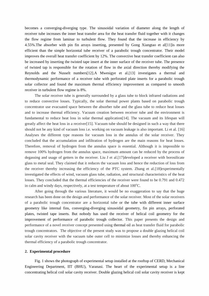
Fig. 2 shows actual design dimensions of double glazing helical coil solar cavity
receiver. The geometrical parameters and material specifications are given in Tab.1.
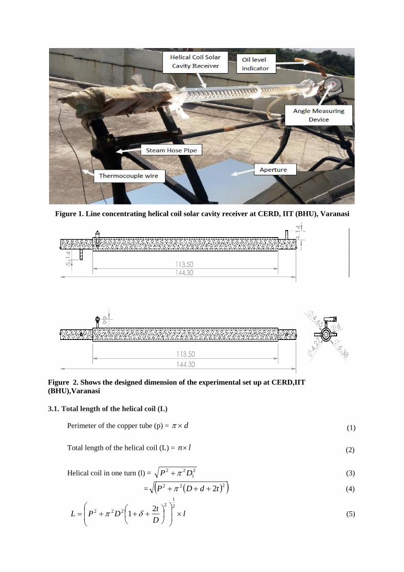
Figure 1. Line concentrating helical coil solar cavity receiver at CERD, IIT (BHU), Varanasi
Figure 2. Shows the designed dimension of the experimental set up at CERD,IIT
(BHU),Varanasi
3.1. Total length of the helical coil (L)
Perimeter of the copper tube (p) = d (1)
Total length of the helical coil (L) = ln (2)
Helical coil in one turn (l) = 2
1
22 DP
(3)
= 222 2tdDP
(4)
2
1 2
1
2
222 lD
tDPL
(5)
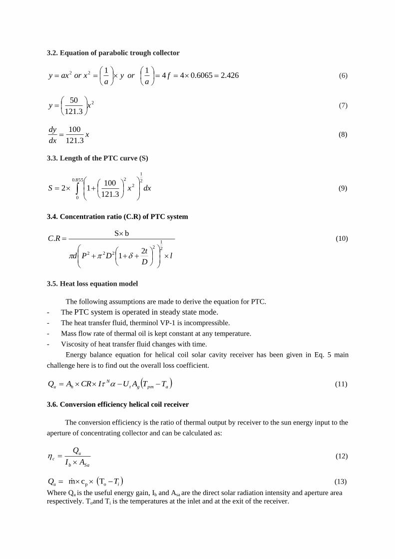
3.2. Equation of parabolic trough collector
426.26065.0441
1
22
f
aory
axoraxy
(6)
3.121
50 2xy
(7)
xdx
dy
3.121
100
(8)
3.3. Length of the PTC curve (S)
3.121
10012
855.0
0
2
1
2
2
dxxS
(9)
3.4. Concentration ratio (C.R) of PTC system
2
1
bS.
2
12
222 lD
tDPd
RC
(10)
3.5. Heat loss equation model
The following assumptions are made to derive the equation for PTC.
- The PTC system is operated in steady state mode.
- The heat transfer fluid, therminol VP-1 is incompressible.
- Mass flow rate of thermal oil is kept constant at any temperature.
- Viscosity of heat transfer fluid changes with time.
Energy balance equation for helical coil solar cavity receiver has been given in Eq. 5 main
challenge here is to find out the overall loss coefficient.
apmgt
N
hu TTAUICRAQ (11)
3.6. Conversion efficiency helical coil receiver
The conversion efficiency is the ratio of thermal output by receiver to the sun energy input to the
aperture of concentrating collector and can be calculated as:
Sab
u
cAI
Q
(12)
T cm op iu TQ
(13)
Where Qu is the useful energy gain, Ib and Asa are the direct solar radiation intensity and aperture area
respectively. Toand Ti is the temperatures at the inlet and at the exit of the receiver.
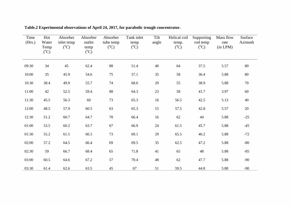
Table.2 Experimental observations of April 24, 2017, for parabolic trough concentrator.
Time
(Hrs.)
Hot
Water
Temp
(oC)
Absorber
inlet temp
(oC)
Absorber
outlet
temp
(oC)
Absorber
tube temp
(oC)
Tank inlet
temp
(oC)
Tilt
angle
Helical coil
temp.
(oC)
Supporting
rod temp
(oC)
Mass flow
rate
(in LPM)
Surface
Azimuth
09:30 34 45 62.4 88 51.4 40 64 37.5 5.57 80
10:00 35 45.9 54.6 75 57.1 35 58 36.4 5.88 80
10:30 38.4 49.9 55.7 74 68.6 29 55 38.9 5.88 70
11:00 42 52.5 59.4 88 64.3 23 58 41.7 3.97 60
11:30 45.5 56.3 60 73 65.3 16 56.5 42.5 5.13 40
12:00 48.5 57.9 60.5 63 65.3 15 57.5 42.8 5.57 20
12:30 51.2 60.7 64.7 78 66.4 16 62 44 5.88 -25
01:00 53.5 60.2 63.7 67 66.9 24 61.5 45.7 5.88 -45
01:30 55.2 61.5 66.5 73 69.1 29 65.5 46.2 5.88 -72
02:00 57.2 64.5 66.4 69 69.5 35 62.5 47.2 5.88 -80
02:30 59 66.7 68.4 65 71.8 41 65 48 5.88 -85
03:00 60.5 64.6 67.2 57 70.4 48 62 47.7 5.88 -90
03:30 61.4 62.6 63.5 45 67 51 59.5 44.8 5.88 -90
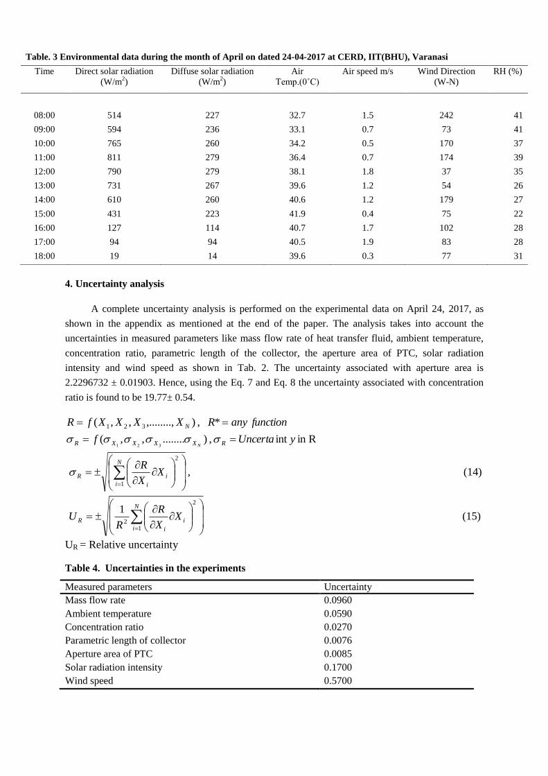
4. Uncertainty analysis
A complete uncertainty analysis is performed on the experimental data on April 24, 2017, as
shown in the appendix as mentioned at the end of the paper. The analysis takes into account the
uncertainties in measured parameters like mass flow rate of heat transfer fluid, ambient temperature,
concentration ratio, parametric length of the collector, the aperture area of PTC, solar radiation
intensity and wind speed as shown in Tab. 2. The uncertainty associated with aperture area is
2.2296732 ± 0.01903. Hence, using the Eq. 7 and Eq. 8 the uncertainty associated with concentration
ratio is found to be 19.77± 0.54.
Rin int , )........,,(
* , ),........,,,(
321
321
yUncertaf
functionanyRXXXXfR
RXXXXR
N
N
, 1
2
N
i
i
i
R XX
R (14)
1
1
2
2
N
i
i
i
R XX
R
RU (15)
UR = Relative uncertainty
Table 4. Uncertainties in the experiments
Measured parameters Uncertainty
Mass flow rate
Ambient temperature
Concentration ratio
Parametric length of collector
Aperture area of PTC
Solar radiation intensity
Wind speed
0.0960
0.0590
0.0270
0.0076
0.0085
0.1700
0.5700
Table. 3 Environmental data during the month of April on dated 24-04-2017 at CERD, IIT(BHU), Varanasi
Time Direct solar radiation
(W/m2)
Diffuse solar radiation
(W/m2)
Air
Temp.(0˚C)
Air speed m/s Wind Direction
(W-N)
RH (%)
08:00 514 227 32.7 1.5 242 41
09:00 594 236 33.1 0.7 73 41
10:00 765 260 34.2 0.5 170 37
11:00 811 279 36.4 0.7 174 39
12:00 790 279 38.1 1.8 37 35
13:00 731 267 39.6 1.2 54 26
14:00 610 260 40.6 1.2 179 27
15:00 431 223 41.9 0.4 75 22
16:00 127 114 40.7 1.7 102 28
17:00 94 94 40.5 1.9 83 28
18:00 19 14 39.6 0.3 77 31
5. Results and discussion
The performance analysis has been done using experimental data obtained on the experimental
setup on typical days March, April 2017. In the present experimental setup, losses have been
minimized using helical coil solar cavity receiver with the double glazing vacuum tube outer cell. The
present research provides a comprehensive design of helical coil solar cavity receiver and its
performance analysis under the Varanasi climatic zone. A blackened helical coil copper absorber tube
was covered with two concentric borosilicate glass having vacuum at annulus, kept at the focal line of
a parabolic trough concentrator. A parabolic trough concentrator with an aperture area of 2.229673 m²
and receiver area of 0.113716 m² was kept under solar radiation intensity in such a way that surface
azimuth and tilt angle of the system became equal to solar azimuth and zenith angle respectively. The
validation of model used in this analysis has been done using EES software. Input parameters have
been obtained on experimental set updated from 03.04.2017 to 14.05.2017 with the variation of
vacuum pressure from 1 torr to 760 torr. Following are the results which have been obtained on
experimental set up and explained below.
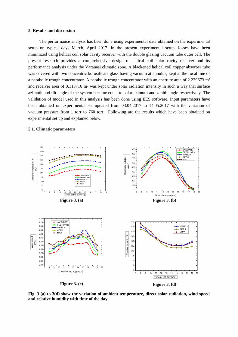
5.1. Climatic parameters
7 8 9 10 11 12 13 14 15 16 17 18 19
0
5
10
15
20
25
30
35
40
45
50
Am
bie
nt T
em
pe
ratu
re(
oC
)
(Ta)
Time of the day(hr.)
JANUARY
FEBRUARY
MARCH
APRIL
MAY
Figure 3. (a)
7 8 9 10 11 12 13 14 15 16 17 18 19
0
100
200
300
400
500
600
700
800
900
Dir
ect
so
lar
rad
iatio
n
(W/m
2)
Time of the day(hrs.)
JANUARY
FEBRUARY
MARCH
APRIL
MAY
Figure 3. (b)
Figure 3. (c)
7 8 9 10 11 12 13 14 15 16 17 18 19
0
5
10
15
20
25
30
35
40
45
50
Re
lative
hu
mid
ity(%
)
Time of the day(hrs.)
MARCH
APRIL
MAY
Figure 3. (d)
Fig. 3 (a) to 3(d) show the variation of ambient temperature, direct solar radiation, wind speed
and relative humidity with time of the day.
7 8 9 10 11 12 13 14 15 16 17 18 19
0.00
0.25
0.50
0.75
1.00
1.25
1.50
1.75
2.00
2.25
2.50
2.75
3.00
Win
d s
pe
ed
(m/s
)
Time of the day(hrs.)
JANUARY
FEBRUARY
MARCH
APRIL
MAY
From Fig. 3(a) to 3(d) show the variations of environmental parameters like ambient
temperature, direct solar radiation, wind speed and relative humidity with respect to time of the day on
dated January to May, 2017.. High value of air temperature reduces convection loss from helical coil
solar cavity receiver. Parabolic trough technology performs well at high value of direct radiation and
low value of air speed. Solar radiation intensity, Wind speed and its direction were measured by
weather monitoring station installed at roof top near experimental set up at CERD, IIT (BHU). Fig.
3(c) shows clearly that the wind speed is fluctuating in nature with respect to time of the day thereby
too much sensitive in the performance analysis of PTC system. Direction of air speed plays vital role
in losses because parabolic trough concentrator is a line concentrating unit. When air flows along the
length of helical coil, losses will be higher in comparison to the flow of air in any other directions.
Relative humidity affects the solar radiation intensity. Increase in the value of relative humidity will
increase the percentage of water droplets thereby increase in scattering effect and hence reduce the
intensity of solar radiation. Optical path length is also affected by relative humidity. Direct solar
radiation intensity reduces as the optical path length or air mass increases during the day hour.
Environmental parameters are vital in solar thermal applications and hence environmental data
analysis is important for the best study of solar parabolic trough concentrated technology.
5.2. Performance parameters
5.2.1 Conversion efficiency
In this section, an experimental analysis to determine the performance of the parabolic trough
concentrator has been carried out under the climatic conditions of Varanasi (Latitude 25.31 and
Longitude: 82.97), Uttar Pradesh, India. Since, the meteorological cycle on average repeats itself every
year, the results presented here would be invariant of change in year. Fig. 4 shows the comparision
between the helical coil receiver and the horizontal tube receiver of the parabolic trough concentrator
in terms of conversion efficiency.
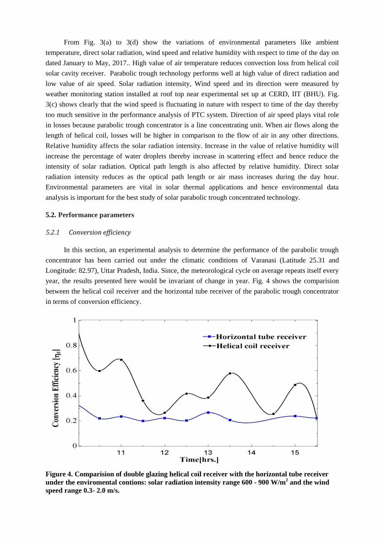
Figure 4. Comparision of double glazing helical coil receiver with the horizontal tube receiver
under the enviromental contions: solar radiation intensity range 600 - 900 W/m2 and the wind
speed range 0.3- 2.0 m/s.
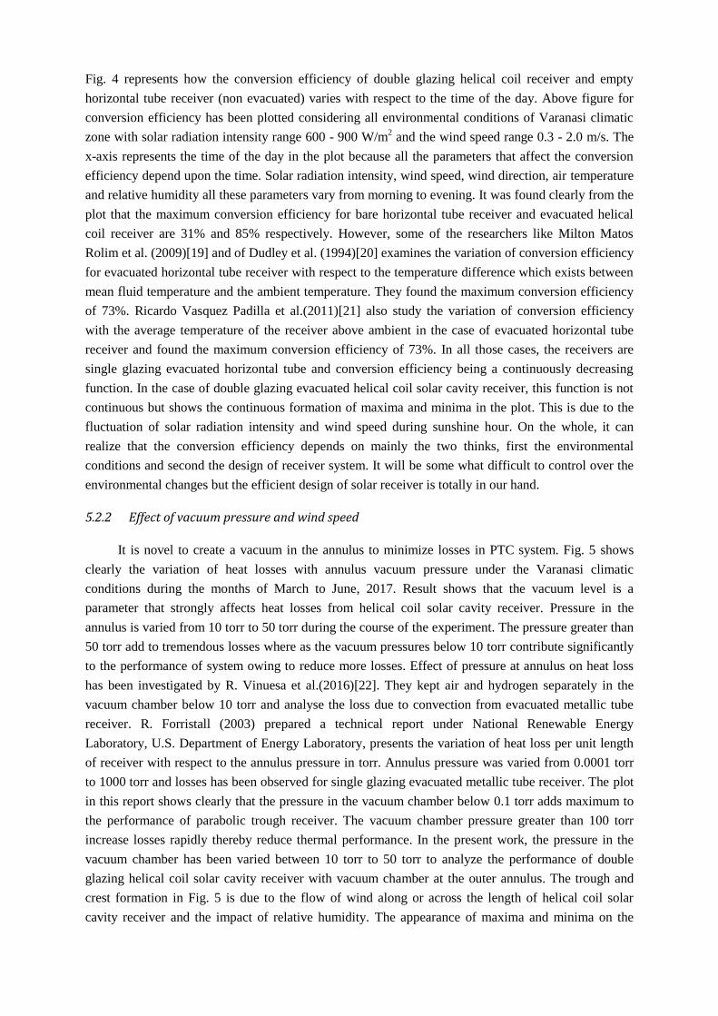
Fig. 4 represents how the conversion efficiency of double glazing helical coil receiver and empty
horizontal tube receiver (non evacuated) varies with respect to the time of the day. Above figure for
conversion efficiency has been plotted considering all environmental conditions of Varanasi climatic
zone with solar radiation intensity range 600 - 900 W/m2 and the wind speed range 0.3 - 2.0 m/s. The
x-axis represents the time of the day in the plot because all the parameters that affect the conversion
efficiency depend upon the time. Solar radiation intensity, wind speed, wind direction, air temperature
and relative humidity all these parameters vary from morning to evening. It was found clearly from the
plot that the maximum conversion efficiency for bare horizontal tube receiver and evacuated helical
coil receiver are 31% and 85% respectively. However, some of the researchers like Milton Matos
Rolim et al. (2009)[19] and of Dudley et al. (1994)[20] examines the variation of conversion efficiency
for evacuated horizontal tube receiver with respect to the temperature difference which exists between
mean fluid temperature and the ambient temperature. They found the maximum conversion efficiency
of 73%. Ricardo Vasquez Padilla et al.(2011)[21] also study the variation of conversion efficiency
with the average temperature of the receiver above ambient in the case of evacuated horizontal tube
receiver and found the maximum conversion efficiency of 73%. In all those cases, the receivers are
single glazing evacuated horizontal tube and conversion efficiency being a continuously decreasing
function. In the case of double glazing evacuated helical coil solar cavity receiver, this function is not
continuous but shows the continuous formation of maxima and minima in the plot. This is due to the
fluctuation of solar radiation intensity and wind speed during sunshine hour. On the whole, it can
realize that the conversion efficiency depends on mainly the two thinks, first the environmental
conditions and second the design of receiver system. It will be some what difficult to control over the
environmental changes but the efficient design of solar receiver is totally in our hand.
5.2.2 Effect of vacuum pressure and wind speed
It is novel to create a vacuum in the annulus to minimize losses in PTC system. Fig. 5 shows
clearly the variation of heat losses with annulus vacuum pressure under the Varanasi climatic
conditions during the months of March to June, 2017. Result shows that the vacuum level is a
parameter that strongly affects heat losses from helical coil solar cavity receiver. Pressure in the
annulus is varied from 10 torr to 50 torr during the course of the experiment. The pressure greater than
50 torr add to tremendous losses where as the vacuum pressures below 10 torr contribute significantly
to the performance of system owing to reduce more losses. Effect of pressure at annulus on heat loss
has been investigated by R. Vinuesa et al.(2016)[22]. They kept air and hydrogen separately in the
vacuum chamber below 10 torr and analyse the loss due to convection from evacuated metallic tube
receiver. R. Forristall (2003) prepared a technical report under National Renewable Energy
Laboratory, U.S. Department of Energy Laboratory, presents the variation of heat loss per unit length
of receiver with respect to the annulus pressure in torr. Annulus pressure was varied from 0.0001 torr
to 1000 torr and losses has been observed for single glazing evacuated metallic tube receiver. The plot
in this report shows clearly that the pressure in the vacuum chamber below 0.1 torr adds maximum to
the performance of parabolic trough receiver. The vacuum chamber pressure greater than 100 torr
increase losses rapidly thereby reduce thermal performance. In the present work, the pressure in the
vacuum chamber has been varied between 10 torr to 50 torr to analyze the performance of double
glazing helical coil solar cavity receiver with vacuum chamber at the outer annulus. The trough and
crest formation in Fig. 5 is due to the flow of wind along or across the length of helical coil solar
cavity receiver and the impact of relative humidity. The appearance of maxima and minima on the
above plot is very interesting and it includes the effect of all environmental parameters described
earlier. Solar radiation intensity on earth’s surface is affected by relative humidity but it is beam
radiation, not the global radiation that is affected by relative humidity.
10 20 30 40 50
14
16
18
20
22
24
He
at L
oss(J
)
Vacuum Pressure(Torr)
Figure 5. Shows the variation of heat loss with
respect to vacuum pressure
10 20 30 40 50 60
0
200
400
600
800
1000
1200
1400
He
at(
J)
Vacuum Pressure(Torr)
Heat loss
Useful heat Energy
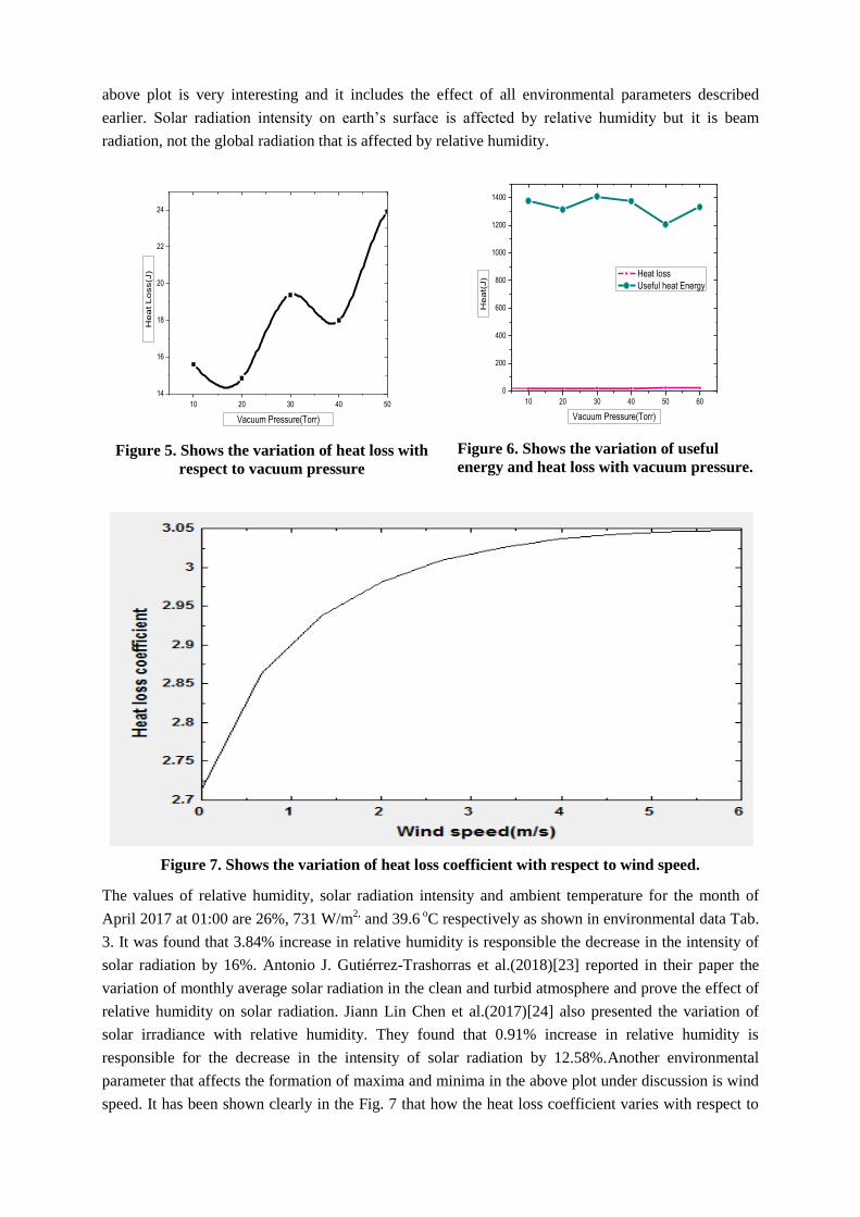
Figure 6. Shows the variation of useful
energy and heat loss with vacuum pressure.
Figure 7. Shows the variation of heat loss coefficient with respect to wind speed.
The values of relative humidity, solar radiation intensity and ambient temperature for the month of
April 2017 at 01:00 are 26%, 731 W/m2, and 39.6
oC respectively as shown in environmental data Tab.
3. It was found that 3.84% increase in relative humidity is responsible the decrease in the intensity of
solar radiation by 16%. Antonio J. Gutiérrez-Trashorras et al.(2018)[23] reported in their paper the
variation of monthly average solar radiation in the clean and turbid atmosphere and prove the effect of
relative humidity on solar radiation. Jiann Lin Chen et al.(2017)[24] also presented the variation of
solar irradiance with relative humidity. They found that 0.91% increase in relative humidity is
responsible for the decrease in the intensity of solar radiation by 12.58%.Another environmental
parameter that affects the formation of maxima and minima in the above plot under discussion is wind
speed. It has been shown clearly in the Fig. 7 that how the heat loss coefficient varies with respect to
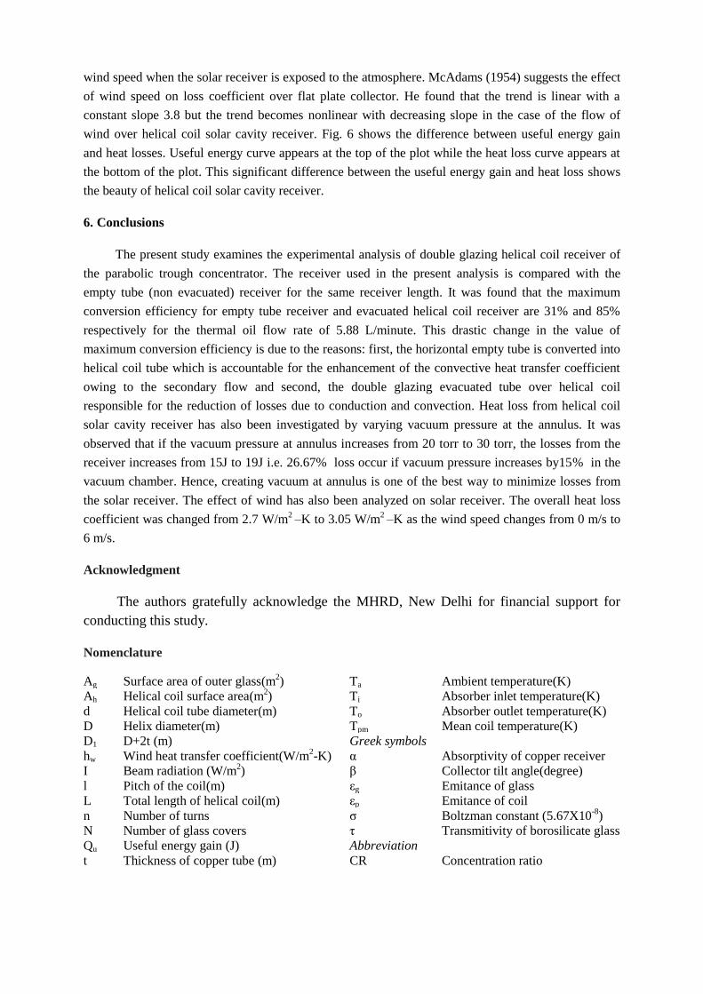
wind speed when the solar receiver is exposed to the atmosphere. McAdams (1954) suggests the effect
of wind speed on loss coefficient over flat plate collector. He found that the trend is linear with a
constant slope 3.8 but the trend becomes nonlinear with decreasing slope in the case of the flow of
wind over helical coil solar cavity receiver. Fig. 6 shows the difference between useful energy gain
and heat losses. Useful energy curve appears at the top of the plot while the heat loss curve appears at
the bottom of the plot. This significant difference between the useful energy gain and heat loss shows
the beauty of helical coil solar cavity receiver.
6. Conclusions
The present study examines the experimental analysis of double glazing helical coil receiver of
the parabolic trough concentrator. The receiver used in the present analysis is compared with the
empty tube (non evacuated) receiver for the same receiver length. It was found that the maximum
conversion efficiency for empty tube receiver and evacuated helical coil receiver are 31% and 85%
respectively for the thermal oil flow rate of 5.88 L/minute. This drastic change in the value of
maximum conversion efficiency is due to the reasons: first, the horizontal empty tube is converted into
helical coil tube which is accountable for the enhancement of the convective heat transfer coefficient
owing to the secondary flow and second, the double glazing evacuated tube over helical coil
responsible for the reduction of losses due to conduction and convection. Heat loss from helical coil
solar cavity receiver has also been investigated by varying vacuum pressure at the annulus. It was
observed that if the vacuum pressure at annulus increases from 20 torr to 30 torr, the losses from the
receiver increases from 15J to 19J i.e. 26.67% loss occur if vacuum pressure increases by15% in the
vacuum chamber. Hence, creating vacuum at annulus is one of the best way to minimize losses from
the solar receiver. The effect of wind has also been analyzed on solar receiver. The overall heat loss
coefficient was changed from 2.7 W/m2 –K to 3.05 W/m
2 –K as the wind speed changes from 0 m/s to
6 m/s.
Acknowledgment
The authors gratefully acknowledge the MHRD, New Delhi for financial support for
conducting this study.
Nomenclature
Ag Surface area of outer glass(m2) Ta Ambient temperature(K)
Ah Helical coil surface area(m2) Ti Absorber inlet temperature(K)
d Helical coil tube diameter(m) To Absorber outlet temperature(K)
D Helix diameter(m) Tpm Mean coil temperature(K)
D1 D+2t (m) Greek symbols
hw Wind heat transfer coefficient(W/m2-K) α Absorptivity of copper receiver
I Beam radiation (W/m2) β Collector tilt angle(degree)
l Pitch of the coil(m) εg Emitance of glass
L Total length of helical coil(m) εp Emitance of coil
n Number of turns σ Boltzman constant (5.67X10⁻⁸
)
N Number of glass covers τ Transmitivity of borosilicate glass
Qu Useful energy gain (J) Abbreviation
t Thickness of copper tube (m) CR Concentration ratio

References
[1] E. Bellos, C. Tzivanidis, A detailed exergetic analysis of parabolic trough collectors, Energy
Convers. Manag. 149 (2017) 275–292. doi:10.1016/j.enconman.2017.07.035.
[2] M. Biencinto, L. González, E. Zarza, L.E. Díez, J. Muñoz-antón, Performance model and
annual yield comparison of parabolic-trough solar thermal power plants with either nitrogen or
synthetic oil as heat transfer fluid, Energy Convers. Manag. J. 87 (2014) 238–249.
[3] H.K. Eck M, Heat transfer fluids for future parabolic trough solar thermal power plants., in:
Proc. ISES World Congr., 2007.
[4] X.R. Cheng ZD, He YL, Xiao J, Tao YB, Three–dimensional numerical study of heat transfer
characteristics in the receiver tube of parabolic trough solar collector., Int Commun Heat Mass.
37 (2010) 782–7.
[5] T.W. Qiu Y, Li MJ, He YL, Thermal performance analysis of a parabolic trough solar collector
using supercritical CO2 as heat transfer fluid under non–uniform solar flux, Appl Therm Eng.
115 (2017) 1255–1265.
[6] O.A. Hachicha AA, Rodríguez I, Capdevila R, Heat transfer analysis and numerical simulation
of a parabolic trough solar collector, Appl Energy. 111 (2013) 581–92.
[7] S.S. Khanna S, Kedare SB, Deflection and stresses in absorber tube of solar parabolic trough
due to circumferential and axial flux variations on absorber tube supported at multiple points,
Sol Energy 2014;99(1)134–51. 99 (2015) 134–51.
[8] K.S. Khanna S, Singh S, Explicit expressions for temperature distribution and deflection in
absorber tube of solar parabolic trough concentrator., Sol Energy 2015;114289–302. 114
(2015) 289–302.
[9] E. Bellos, C. Tzivanidis, D. Tsimpoukis, Thermal enhancement of parabolic trough collector
with internally fi nned absorbers, Sol. Energy. 157 (2017) 514–531.
doi:10.1016/j.solener.2017.08.067.
[10] E. Bellos, C. Tzivanidis, K.A. Antonopoulos, G. Gkinis, Thermal enhancement of solar
parabolic trough collectors by using nano fl uids and converging-diverging absorber tube,
Renew. Energy J. 94 (2016) 213–222.
[11] G. Xiangtao, W. Fuqiang, W. Haiyan, T. Jianyu, L. Qingzhi, H. Huaizhi, Heat transfer
enhancement analysis of tube receiver for parabolic trough solar collector with pin fin arrays
inserting, Sol. Energy. 144 (2017) 185–202. doi:10.1016/j.solener.2017.01.020.
[12] M.R. O.A. Jaramillo*, Monica Borunda , K.M. Velazquez-Lucho, Parabolic trough solar
collector for low enthalpy processes : An analysis of the ef fi ciency enhancement by using
twisted tape inserts, Renew. Energy J. 93 (2016) 125–141.
[13] A. Mwesigye, T. Bello-ochende, J.P. Meyer, Heat transfer and thermodynamic performance of
a parabolic trough receiver with centrally placed perforated plate inserts, Appl. Energy J. 136
(2014) 989–1003.
[14] L.D. Li J, Wang Z, Li J, Vacuum reliability analysis of parabolic trough receiver, Sol Energy
Mater Sol Cells. 105 (2012) 302–8.
[15] L.Q. Liu J, Lei D, Vacuum lifetime and residual gas analysis of parabolic trough receiver,
Renew Energy. 86 (2016) 949–54.
[16] W.Z. Lei D, Wang Z, Li J, Li J, Experimental study of glass to metal seals for parabolic trough
receivers, Renew Energy. 48 (2012) 85–91.
[17] W.Z. Lei D, Wang Z, Li J, Li J, Experimental study of glass to metal seals for parabolic trough
receivers, Renew Energy. 48 (2012) 85–95.
[18] L. Zhang, W. Wang, Z. Yu, L. Fan, Y. Hu, Y. Ni, An experimental investigation of a natural
circulation heat pipe system applied to a parabolic trough solar collector steam generation
system, Sol. Energy. 57 (2012) 262–268.
[19] M.M. Rolim, N. Fraidenraich, C. Tiba, Analytic modeling of a solar power plant with parabolic
linear collectors, Sol. Energy. 83 (2009) 126–133. doi:10.1016/j.solener.2008.07.018.
[20] Dudley, V., Kolb, G.J., Mahoney, A.R., Mancini, T.R., Matthews, C.W., Sloan, M., Kearney,
D., 1994. Test Results: SEGS LS-2 Solar Collector. SAND 94-1884. Sandia National
Laboratories, Albuquerque, NM., n.d.
[21] M.M.R. Ricardo Vasquez Padilla, Gokmen Demirkaya , D. Yogi Goswamic, Elias Stefanakos,
Heat transfer analysis of parabolic trough solar receiver, Appl. Energy. 88 (2011) 5097–5110.

doi:10.1016/j.apenergy.2011.07.012.
[22] L.F. de A. R. Vinuesa, and H.C. evalo, M. Luna, Simulations and experiments of heat loss
from a parabolic trough absorber tube over a range of pressures and gas compositions in the
vacuum chamber, J. Renew. Sustain. ENERGY. 8 (2016) 23701–16. doi:10.1063/1.4944975.
[23] A.J. Gutiérrez-trashorras, E. Villicaña-ortiz, E. Álvarez-álvarez, J.M. González-caballín, J.
Xiberta-bernat, M.J. Suarez-lópez, Attenuation processes of solar radiation . Application to the
quanti fi cation of direct and di ff use solar irradiances on horizontal surfaces in Mexico by
means of an overall atmospheric transmittance, 81 (2018) 93–106.
[24] G.Y.C. and G.Y.Y. Jiann Lin Chen, Hsiang Tse Tseng, Study for the Irradiance Attenuation on
the Cover of Solar, in: 2nd Int. Conf. Adv. Clean Energy Res. ICACER 2017, 7-9 April 2017
Berlin, Ger., 2017: pp. 79–87.