Embed Size (px)
Citation preview
UNCLASSIFIED: Dist A. Approved for public release
Thermal Management of Vehicle Electronic Payloads Using Nanofluids and
Thermoelectric Devices — Modeling and Analysis
Authors:
David J. Ewing, Joshua Finn, Lin Ma, PhD., John Wagner, PhD., PE.
Affiliation:
Clemson University, Department of Mechanical Engineering, Clemson, SC 29634
Abstract
Electronic payloads have become an integral part of modern military ground vehicles.
These electronics often feature high thermal density that must be effectively managed,
especially under demanding operating conditions, to maintain system reliability. This paper
describes the modeling and analysis of nanofluids and thermoelectric devices to address the
cooling challenges posed by these thermal loads. A sensitivity analysis has been performed to
investigate the suitability of a particular nanofluid model. Numerical results obtained show
that the convective heat transfer coefficient can be enhanced up to 16.1% with the
augmentation of nanoparticles into the base fluid (water). The simulation results also show
that the peak computer chip temperature varies by only 0.4%, demonstrating that it is
insensitive to the complexity of the selected nanofluid model. Furthermore, the proposed
thermal management system provides cooling performance which would not be possible with
traditional air-cooled heat sinks which remain limited to the ambient temperatures.
Keywords: Nanofluid; thermoelectric; thermal modeling sensitivity; military electronic
cooling; coolant rail; nanoparticles; peak temperature suppression; nodal modeling; effective
properties
1 Introduction
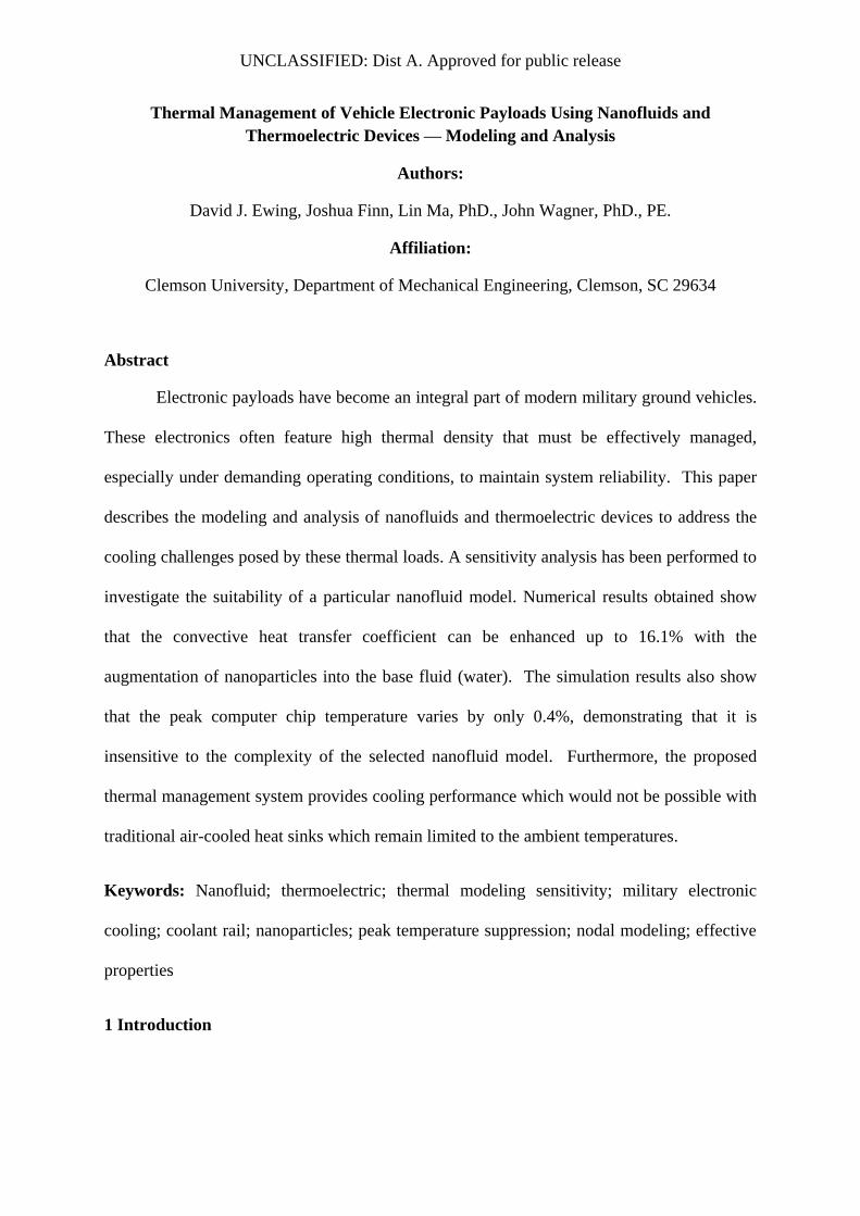
Report Documentation Page Form ApprovedOMB No. 0704-0188
Public reporting burden for the collection of information is estimated to average 1 hour per response, including the time for reviewing instructions, searching existing data sources, gathering andmaintaining the data needed, and completing and reviewing the collection of information. Send comments regarding this burden estimate or any other aspect of this collection of information,including suggestions for reducing this burden, to Washington Headquarters Services, Directorate for Information Operations and Reports, 1215 Jefferson Davis Highway, Suite 1204, ArlingtonVA 22202-4302. Respondents should be aware that notwithstanding any other provision of law, no person shall be subject to a penalty for failing to comply with a collection of information if itdoes not display a currently valid OMB control number.
1. REPORT DATE 01 MAR 2011
2. REPORT TYPE N/A
3. DATES COVERED -
4. TITLE AND SUBTITLE Thermal Management of Vehicle Electronic Payloads UsingNanofluids and Thermoelectric Devices--Modeling and Analysis (PREPRINT)
5a. CONTRACT NUMBER W56HZV-04-2-0001
5b. GRANT NUMBER
5c. PROGRAM ELEMENT NUMBER
6. AUTHOR(S) David J. Ewing; Jouhua Finn; Lin Ma PhD; John Wagner,PhD.,PE
5d. PROJECT NUMBER
5e. TASK NUMBER
5f. WORK UNIT NUMBER
7. PERFORMING ORGANIZATION NAME(S) AND ADDRESS(ES) Clemson University, Department of Mechanical Engineering,Clemson, SC 29634
8. PERFORMING ORGANIZATION REPORT NUMBER
9. SPONSORING/MONITORING AGENCY NAME(S) AND ADDRESS(ES) US Army RDECOM-TARDEC 6501 E 11 Mile Rd Warren, MI48397-5000, USA
10. SPONSOR/MONITOR’S ACRONYM(S) TACOM/TARDEC/RDECOM
11. SPONSOR/MONITOR’S REPORT NUMBER(S) 21547
12. DISTRIBUTION/AVAILABILITY STATEMENT Approved for public release, distribution unlimited
13. SUPPLEMENTARY NOTES Submitted for publication in a Special Issue of Int’l Journal of Vehical Design
14. ABSTRACT
15. SUBJECT TERMS
16. SECURITY CLASSIFICATION OF: 17. LIMITATIONOF ABSTRACT
SAR
18.NUMBEROF PAGES
28
19a. NAME OF RESPONSIBLE PERSON
a. REPORT unclassified
b. ABSTRACT unclassified
c. THIS PAGE unclassified
Standard Form 298 (Rev. 8-98) Prescribed by ANSI Std Z39-18
UNCLASSIFIED
UNCLASSIFIED
Page 2 of 28
Modern military ground vehicles, such as Force Protection’s Cougar MPAV, may
carry a vast array of electronic equipment to perform command and control tasks that require
reliable temperature control to maintain system integrity. Computer hardware continues to
evolve with greater computational abilities and progressively smaller package sizes for a
given power density which raises the heat load on the overall system. Particularly in defense
applications, electronic systems may be operated in a wide range of conditions, including hot
desert climates where heat rejection is difficult due to the decreased differential between the
ambient conditions and the equipment’s maximum operating temperature. To ensure
adequate cooling in adverse environments, a thermal management system must be developed
which is capable of adequately cooling the electronics while maintaining packaging
flexibility and reliable operation in combat environments.
Thermal management technology for automotive applications has begun to use
computer controlled electro-mechanical components for enhanced temperature control
(Mitchell, et al., 2009). Liquid cooling systems lend themselves well to heat transfer in
electronic equipment and are, in fact, currently being used in several computer server and
after-market computational systems (Ellsworth, et al., 2008). Electrically powered cooling
components may be controlled to maintain prescribed temperatures and reduce power
consumption (Pfahnl and Liang, 2004). Recent developments, and accompanying
mathematical models, in heat exchanger design allow improved convective heat transfer
coefficients with better insights into their operation (Robinson, 2009, Tan, et al., 2007). The
primary limitation, however, of standalone liquid cooling remains the required temperature
differential over the ambient conditions which may result in unacceptable device operating
temperatures in hot climates.
UNCLASSIFIED
UNCLASSIFIED
Page 3 of 28
Peltier effect thermoelectric coolers (TEC) have demonstrated attractive cooling
properties for computational applications since they can cool these system components below
ambient temperatures in certain operating regimes (Simons and Chu, 2000). The heat
transfer process occurs without moving parts in the TEC module, thus providing a distinct
advantage over conventional vapor compression cycles. The cooling effect in Peltier devices
is achieved by a current flow through the junction of two dissimilar materials. The cooling
available from TEC’s has enabled processor overclocking capabilities in certain applications
(Wang, Zou and Friend, 2009). Additionally, larger TEC’s may serve multiple computer
chips, such as in multi-core processing, as demonstrated by (Simons, Ellsworth and Chu,
2005). However, an effective means must exist to reject heat to the TEC module and
overcome the generated heat flux.
The successful operation of the TEC system is dependent on the heat rejection
accommodations of the supplemental cooling system. A high capacity cold reservoir is
required for optimal heat rejection. This goal may not be a significant design issue when
space requirements are not imposed, and passive cooling systems such as free convection
may be implemented (Lertsatitthanakorn, et al., 2001). More conventional installations, such
as the ones demonstrated by (Chang, et al., 2009), use forced convection and have proven to
yield adequate performance. Space limitations, however, often demand the implementation
of different cooling technologies, and new electronic systems may feature higher power
densities such that direct air cooling cannot meet the heat rejection demands. Liquid cooling
has proven capable of meeting these demands and is well suited for thermoelectric systems
(Huang, et al., 2010).
The performance of liquid cooling systems can often be improved through the
addition of suspended particulates. Experiments have shown that, by adding nanoparticles
UNCLASSIFIED
UNCLASSIFIED
Page 4 of 28
with much higher thermal conductivity than the base fluid, the thermal transfer properties of
the base fluid are enhanced (Choi, 2009, Godson, et al., 2010, Kakac and Pramuanjaroenkij,
2009, Nguyen, et al., 2007, Wang and Mujumdar, 2007, Wong and Kurma, 2008, Wong and
Castillo, 2010). This heat transfer improvement is attractive for use in thermal management
systems, such as car radiators (Leong, et al., 2010), by providing increased thermal protection
for mission critical components. However, the actual nanofluid mechanisms are still debated
due to the inconsistencies present in the available experimental data and the widely varying
models that have been developed (Godson, et al., 2010, Kakac and Pramuanjaroenkij, 2009,
Wang and Mujumdar, 2007, Wong and Castillo, 2010). The accurate mathematical modeling
of nanofluids remains a debated and uncertain area of research. Due to this uncertainty, it is
highly desirable to directly compare the influence of multiple nanofluid models in
simulations in order to study their significance.
The development of an integrated liquid and TEC cooling system with nanofluid
particles should offer greater design flexibility and modular designs for small electronics
packages. This approach should be well suited to military and avionics applications where
space limitations and high ambient temperatures make cooling difficult. The implementation
of multiple cooling loops so that the thermoelectrics are not in direct contact with their
respective electronic heat loads can eliminate condensation problems and minimize the
cooling footprint on the actual electronic component. Nanofluids should enhance the cooling
performance and reduce the thermal resistance throughout the multiple loop system. Also,
investigation of nanofluid modeling techniques will provide insight into the effectiveness of
various models and demonstrate the effectiveness of the proposed cooling system. The
remainder of the paper has been organized as follows. Section 2 presents the fundamental
concepts of nanofluid modeling. Thermoelectric modeling concepts are provided in Section
3. A thermal system model is introduced in Section 4 for an electronic system case study
UNCLASSIFIED
UNCLASSIFIED
Page 5 of 28
featuring computer chips and cooling components operating in extreme conditions. The
nanofluid models and thermoelectric devices are applied for temperature regulation of a
computer chip with full discussion of the representative numerical results. Finally, the
summary is contained in Section 5.
2 Fundamentals and Modeling of Nanofluids
The issue of cooling electronic payloads has been approached by modeling a system
containing combined thermoelectric and nanofluid technologies to achieve maximum thermal
protection and packaging flexibility. The critical issue of nanofluids property modeling will
be discussed with the introduction of three approaches – classical, Brownian motion, and
empirical data curve fit.
2.1 Nanofluids
Nanofluids have been a source of research for the past several years due to their
observed ability to enhance the thermal transfer properties of base fluid properties
(Chandrasekar and Suresh, 2009, Choi, 2009, Godson, et al., 2010, Kakac and
Pramuanjaroenkij, 2009, Wong and Kurma, 2008). Micron-sized particles were originally
used in research for enhancing the heat transfer properties of cooling fluids; however, these
particles were deemed impractical for many applications since the resultant fluid required
large increases in pumping power and also increased the pipe wall friction which lead to
greater pipe wear (Choi, 2009). However, as research progressed, nano-sized particles were
introduced into these systems and they enhanced the thermal transfer characteristics while
greatly reducing the negative aspects of pumping power and pipe wear, making nanofluids a
much more viable option to use in practical thermal protection systems (Choi, 2009).
While these benefits have been well documented, the actual nanofluid mechanisms
are still debated (Chandrasekar and Suresh, 2009, Choi, 2009, Godson, et al., 2010, Kakac
UNCLASSIFIED
UNCLASSIFIED
Page 6 of 28
and Pramuanjaroenkij, 2009, Wong and Kurma, 2008, Wong and Castillo, 2010). As
revealed from these references, inconsistencies in the experimental data as well as the wide
range of models available regarding nanoparticle enhancement of base fluids remain the
primary causes of this ongoing debate. While thermal fluids property improvements have
been shown to depend on the shape, size, and concentration of the nanoparticles, the
underlying mechanisms have yet to be conclusively decided. Among existing models, the
more prominent descriptions include classic models such as Maxwell’s equation for thermal
conductivity and Einstein’s model for viscosity (Chandrasekar and Suresh, 2009, Nguyen, et
al., 2008), Brownian motion (Batchelor, 1977, Prasher, Bhattacharya and Phelan, 2005), or
simply the utilization of data curve fitting (Wong and Kurma, 2008). The importance of the
latter two models is shown by the strong temperature dependence demonstrated by the
nanofluids (Nguyen, et al., 2008, Wong and Kurma, 2008). These facts, along with the data
inconsistencies, create difficulties in modeling the nanoparticle effects on the thermal transfer
properties of their base fluids. Consequently, the modeling of nanofluids remains an
unresolved research area.
Another difficulty in modeling the overall convective heat transfer coefficient, h, for
the nanofluids is that few studies have been performed to evaluate the viscosity increases of
the base fluids by the addition of nanoparticles (Duangthongsuk and Wongwises, 2009,
Godson, et al., 2010, Kakac and Pramuanjaroenkij, 2009, Nguyen, et al., 2008, Wong and
Kurma, 2008). Although analyses on the combined effects of the nanofluid’s thermal
conductivity and viscosity have been performed in select systems, they must ideally be
established for each proposed application. A practical need exists to establish the sensitivity
of nanofluid models used in the thermal management system within the paper. The models
investigated to describe the nanofluid thermal transfer process include a simple classic,
Brownian motion effects, and experimental curve fitting.
UNCLASSIFIED
UNCLASSIFIED
Page 7 of 28
2.2 Nanofluid Models
As mentioned previously, the modeling of nanofluids remains challenging due to the
lack of consistent data and the continued debate concerning the underlying mechanisms of
nanofluid thermal transfer. Therefore, a sensitivity analysis of the proposed nanofluid models
will be performed to observe the individual model’s effect on the maximum temperature and
the transient temperature profile of the given thermal load (e.g. computer chips). This
analysis should offer insight into the importance of nanofluid model selection while
examining both the thermal conductivity and the viscosity. Models which offered uniform
treatment of the thermal transfer enhancement were chosen to describe the effective thermal
conductivity and the effective viscosity of the nanofluid (i.e. from the classes of classic
volume fraction models, Brownian motion models, and experimental curve fitting).
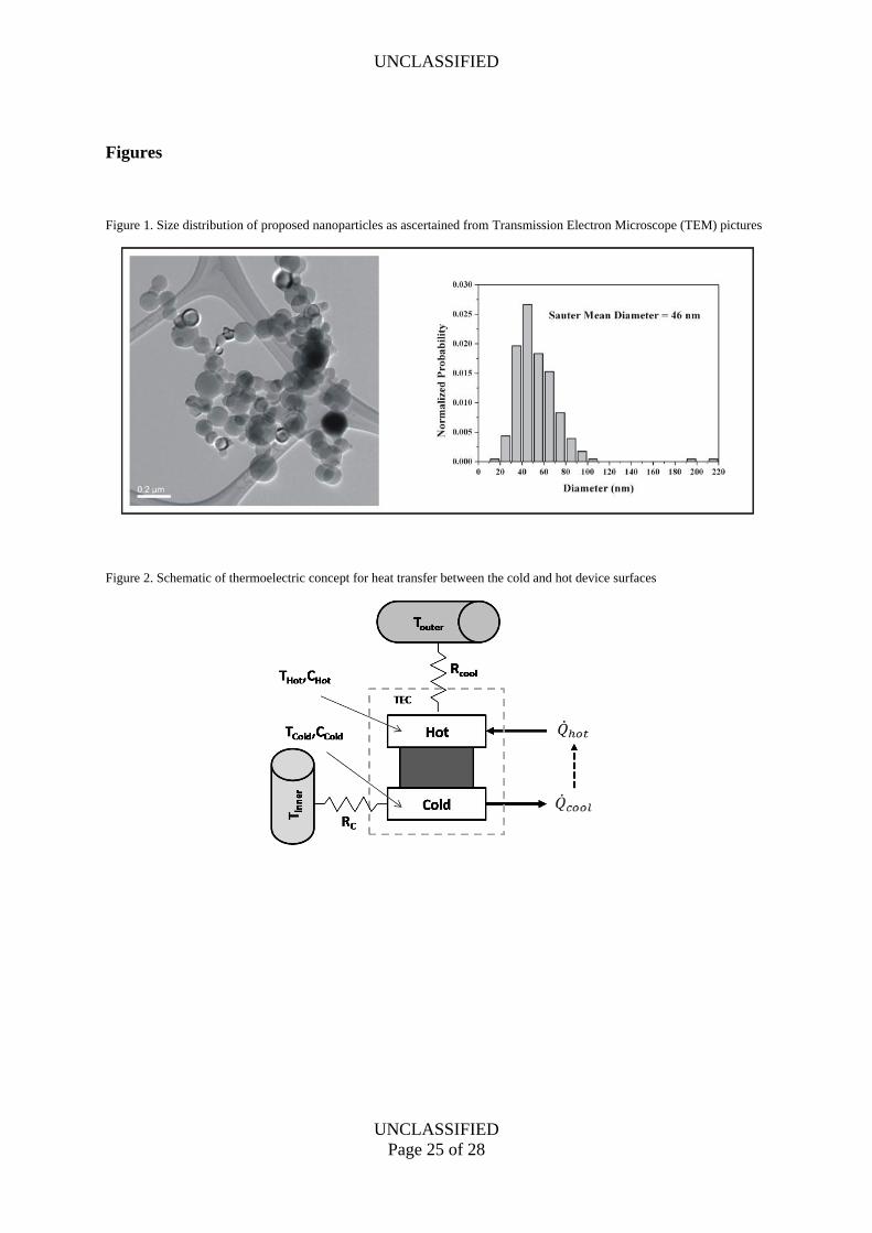
The first analysis task was to determine the size of the nanoparticles for the proposed
system. Figure 1 shows the size distribution of the suggested nanoparticles; the mean
diameter of the nanoparticles was 46 nm. It is important that the size distribution of the
proposed nanoparticles remained consistent with the sizes used in several previous studies,
including (Wong and Kurma, 2008), to ensure consistent modeling conditions. The Dittus-
Boelter equation was used to model the Nusselt number relationship shown in Equation (1)
(Incropera and DeWitt, 1990) to provide a consistent model for the convective heat transfer
coefficient
0.8 0.40.023Re PrDNu (1)
In this expression, the term Nu is the Nusselt number, ReD is the Reynolds number
(ReD= VD/ ), Pr is the Prandtl number (Pr=cp /k), is the density of the base fluid, D is the
diameter of the pipe being used, is the dynamic viscosity, cp is the specific heat capacity,
UNCLASSIFIED
UNCLASSIFIED
Page 8 of 28
and k is the thermal conductivity. From Nu, the convective heat transfer coefficient, h, may
be calculated using Equation (2).
kNu
hD
(2)
2.2.1 Classic Model
The first sensitivity analysis model is based on some classical model features for the
effective thermal conductivity and viscosity of the nanofluid. This approach considers the
volume fraction of the nanoparticles. The mathematical description for the effective thermal
conductivity of the nanofluid has been listed in Equation (3) (Wang and Mujumdar, 2007)
2 2
2
p f p f
eff f
p f p f
k k k kk k
k k k k (3)
In this equation, kp is the nanoparticle thermal conductivity, kf is the base fluid thermal
conductivity, keff is the effective thermal conductivity of the nanofluid, and is the volume
fraction of the nanoparticles. In the latter instance, = 8.47% was assumed for consistency
with the study preformed in (Wong and Kurma, 2008) as discussed in Section 2.2.3.
To describe the effective viscosity of the nanofluid, the model was formulated based
on Einstein’s work and shown in Equation (4) (Nguyen, et al., 2008).
1 2.5eff f
(4)
In this equation, eff is the effective viscosity, and f is the base fluid viscosity.
2.2.2 Brownian Motion Model
UNCLASSIFIED
UNCLASSIFIED
Page 9 of 28
The second model chosen to represent the nanofluid behavior was based upon the
interaction of the particles and the fluid caused by Brownian motion. According to (Prasher,
Bhattacharya and Phelan, 2005), the mechanism that Brownian motion causes is micro-
convection within the base fluid. The proposed model for the effective thermal conductivity
has been shown in Equations (5) and (6) (Prasher, Bhattacharya and Phelan, 2005)
0.3331 2 2 1
1 Re Pr1 2 1
m
eff fk k A
(5)
where
2 181Reb m b
N N N
R k k Tand
d d
(6)
In these two equations, Re is the Reynolds number based upon the base fluid flowing around
the nanoparticle, Pr is the Prandtl number of the base fluid, Rb is the interfacial thermal
resistance between the nanoparticle and the fluid, kb is the Boltzmann constant, T is the
temperature of the fluid, is the kinematic viscosity of the base fluid, N is the density of
the nanoparticle, Nd is the diameter of the nanoparticle, km is the matrix thermal
conductivity, A is a fitting parameter independent of base the fluid, and m is a fitting
parameter dependent of the base fluid. The values of Rb, A, and m were adapted from the
values given in (Prasher, Bhattacharya and Phelan, 2005).
For the effective viscosity of the nanofluid considering Brownian motion, the model
developed by (Batchelor, 1977), given in Equation (7), was utilized
21 2.5 6.5eff f
(7)
2.2.3 Experimental Data Model
UNCLASSIFIED
UNCLASSIFIED
Page 10 of 28
The final senstivity analysis model considered was based on curve fitting
experimental data presented in (Wong and Kurma, 2008). The authors presented
experimental data for several volume fractions of nanoparticles for both thermal conductivity
and viscosity at various nanofluid temperatures. The data indicated a linear increase in
thermal conductivity with an increase of temperature, while the viscosity decreased
exponentially. The volume fraction of = 8.47% was used to find the effective thermal
conductivity and viscosity. The curve equations for the thermal conductivity and viscosity
have been summarized in Equations (8) and (9)
0.0024 0.6275effk T
(8)
6 0.0233 10 T
eff e
(9)
3 Thermoelectric Model
The heat transfer behavior of a Peltier effect device, illustrated in Figure 2, is
generally regulated by the flow of current, i, through the unit. The current flow is dependent
on both the unit’s electrical properties and the hot and cold side temperatures. Thus, the
relationship for current depends on the unit supply voltage, Vi, electrical resistance, RTEC, and
the temperatures of the two plates, TH and TC, as shown in Equation (10).
1 1
i H C i
TEC TEC
i V T T VR R
(10)
The parameter α denotes the Seibec coefficient of the thermoelectric material (note that 0 )
(Dai, Wang and Ni, 2003). Since α is small, its effect may be neglected for ease of analysis
in this case. The power, P, consumed by the thermoelectric device may be expressed in
Equation (11).
UNCLASSIFIED
UNCLASSIFIED
Page 11 of 28
2 2
TEC TEC H C TECP i R iR T T i R (11)
The heat removal equation for the cold side of the TEC can be described based on the
electrical resistance, Peltier effect, and thermal conductivity so that the heat removed, coldQ , is
given in Equation (12) by (Baumann, 2006)
21
22
cold avg TEC TEC TEC H CQ n iT i R A k T T (12)
In this expression, 0.5avg H CT T T , and n is the number of thermoelectric couples in the TEC.
The parameter α may not be neglected from Equation (12) since n is sufficiently large (n ≈
102). Using Ohm’s law, the heat transfer behavior may be expressed in Equation (13) in
terms of the supply voltage.
2
12
2
i icold avg TEC TEC H C
TEC TEC
V VQ n T A k T T
R R (13)
For TEC devices, the thermal conductivity influences both the hot and cold side
temperatures, and the resistance heat is shared. The heat added to the component’s hot side
may be written in Equation (14) as (Riffat and Ma, 2003)
2
12
2
i ihot avg TEC TEC H C
TEC TEC
V VQ n T A k T T
R R (14)
A power-saving strategy has been implemented in the thermoelectric system so that
the devices operate when their respective CPU’s experience an elevated temperature. The
control structure in Equation (14) takes the form of a digital thermostat so that the unit’s
supply voltage, Vi, becomes
UNCLASSIFIED
UNCLASSIFIED
Page 12 of 28
,
,
, ,
,
;
;
0 ;
C in i high
C in i low
i in i low C in i high
high low
C in i low
V T T T
T T TV V T T T T T
T T
T T T
(15)
4 Case Study – Nanofluid Based Thermoelectric Cooling System
The nanofluid models previously discussed in Section 2 will be combined with
thermoelectric devices from Section 3 and applied to a mobile electronic system subject to
desert operating conditions to evaluate cooling effectiveness. The overall performance will
be assessed by studying the temperature profile and peak temperatures of the computer chips
as well as the increase of the convective heat transfer coefficient. Also, the sensitivity of the
system response will be evaluated by comparing the peak temperatures of the three nanofluid
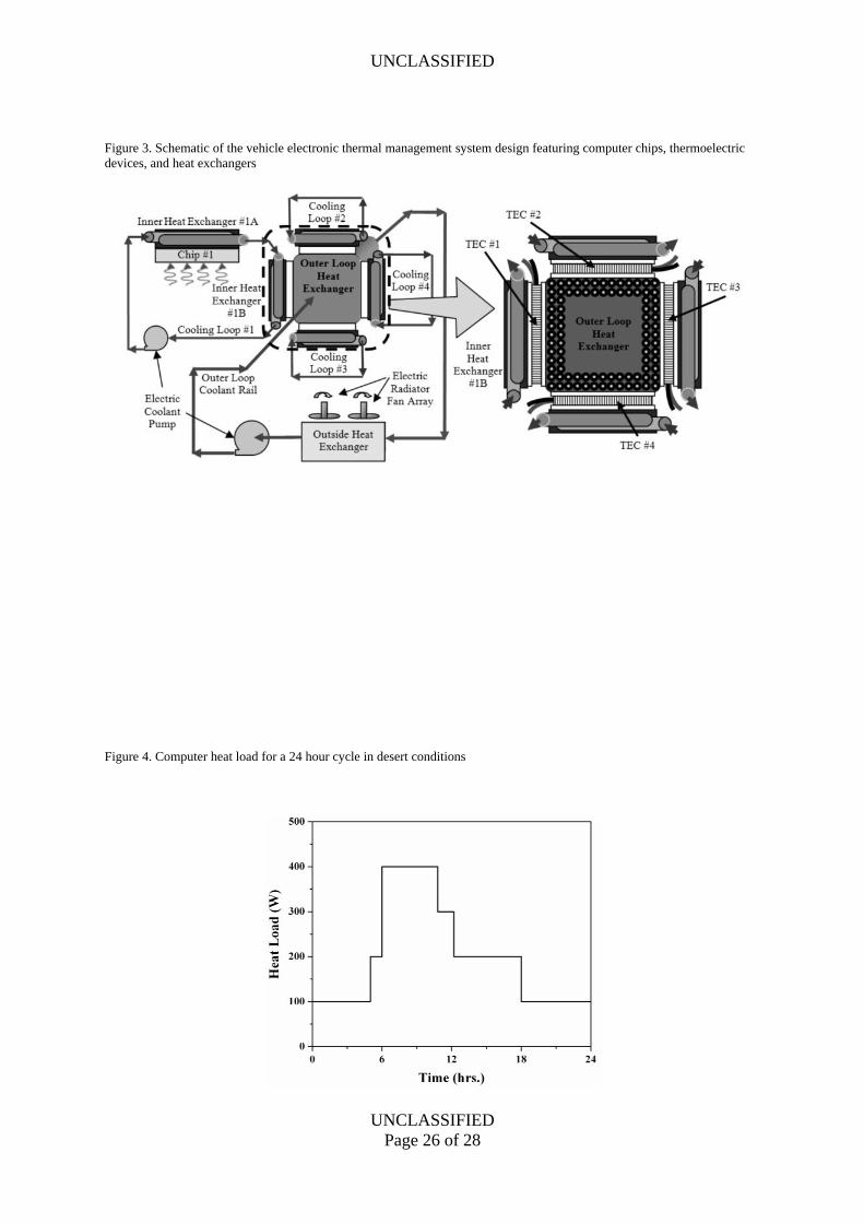
models utilized. To begin the case study, the vehicle electronics system will be described
with an accompanying mathematical model. This system was designed with multiple coolant
loops to enable modular design and maximize packaging flexibility for space limited
applications, as shown in Figure 3. This flexibility is achieved by isolating the thermoelectric
devices from their respective computer chips so that pressure mounting hardware need not be
applied to the circuit board.
4.1 Vehicle Electronic Thermal Management Model
Nodal equations may be used to describe the thermal response of each of the system’s
primary components as illustrated in Figure 3. A lumped capacitance model uses a set of
ordinary differential equations representing the various temperature nodes. This method
models the heat transfer process based upon the thermal resistances, Ri, and the heat
capacitances, Cj within the system. Thus, the thermal response of the jth thermal node, Tj,
may be stated in Equation (16) as
UNCLASSIFIED
UNCLASSIFIED
Page 13 of 28
1, 1,2,...,j j i j j
i i
C T T T Q j nR
(16)
where is the corresponding heat load, and n is the total number of nodes. For this model,
thermal resistances, Ri, consider both convection and conduction heat transfer while
neglecting radiation effects. The nanofluid properties are temperature dependent and must be
carefully treated within the computer algorithm. An example formulation considers the
interaction between an inner coolant loop and two TEC nodes which may be described by
Equation (17)
, , , , , , , , , , ,
, , , ,
, , , , , ,
, ,
, , , , ,
,
1 1
1
1
cool in i cool in i cold i cool in i C i cool in i i
cool in i cool in i
cold i cold i cool in i cold i cold i
cool in i
hot i hot i cool out hot i hot i
cool out
C T T T T TR R
C T T T QR
C T T T QR
(17)
In this expression, the subscript C,i denotes the ith CPU node, Tcool,in,i is the average
temperature of the associated inner coolant loop, and Tcool,out is the average temperature of the
outer cooling loop. The convective thermal resistances are defined as Rcool,in,i =
1/(Acool,inhcool,in,i) and Rcool,out = 1/(Acool,outhcool,out), where A is the surface area of the associated
heat exchanger, and h is the convective heat transfer coefficient. The interfacial thermal
contact resistance of the TEC/heat exchanger interface is negligible when compared to the
other system thermal resistances and so has been ignored.
The standard formulations for the convective and conductive thermal resistances have
been implemented and the nodes compiled into a suite of nodal equations (Finn, et al., 2010).
The state-space formulation has the form x Ax Bu with the state and input vectors, 17 1x
and 7 1u , respectively.
4.2 Test Conditions
UNCLASSIFIED
UNCLASSIFIED
Page 14 of 28
The effect of the three nanofluid models described in Sections 2.2.1-2.2.3 on the
system response was studied in the proposed multiple loop cooling system. The high
temperature ambient conditions were provided based on a cyclic pattern for desert climates.
A variable heat load was imposed by setting the individual computers to cycle on and off
during the 24 hour time interval considered. This procedure resulted in the step changes
shown in Figure 4 with the maximum load being allowed to coincide with the peak ambient
temperature. The changes in heat load allow for observation of the transient behavior of the
system as would be observed in actual operation. The system parameter values were
determined from material properties, geometry, and environmental conditions. The model
was simulated in the Matlab/Simulink environment with an integration time step of Δt = 0.10
s. A complete summary of the modeling parameters are given in Table 1. For ease of
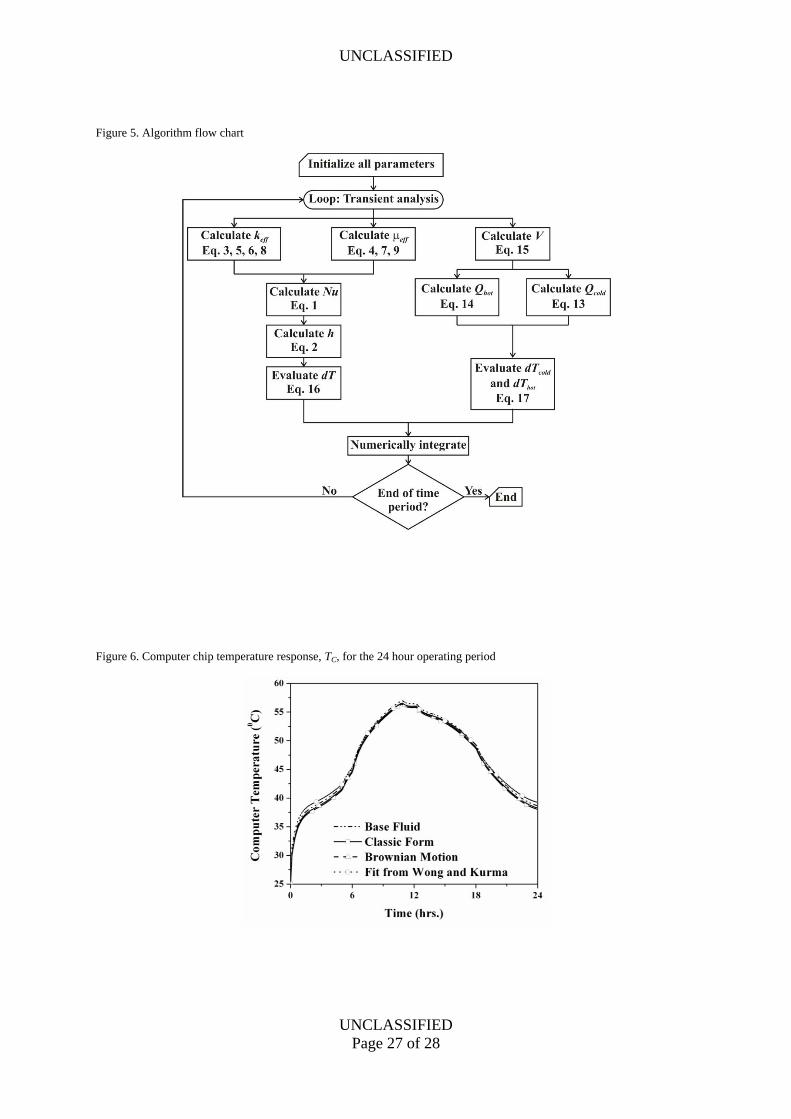
reference, a flow chart is presented in Figure 5 to show the order of the simulation process.
4.3 Thermal Protection – Transient Computer Temperature Analysis
The thermal management system limited the peak temperature of the computer chips.
In Figure 6, the transient temperature profile has been displayed for a single computer chip
for the given 24 hour operating period using water (Base Fluid), the Classical Model (Classic
Form), the Brownian Motion Model (Brownian Motion), and the Experimental Data Model
(Fit from Wong and Kurma). Table 2 summarizes the maximum computer chip
temperatures, nanofluid temperatures, and convective heat transfer coefficient values. From
Figure 6 and Table 2, it can be observed that the nanofluids only decreased the peak
computer chip temperature by 0.60C. The reason for this small temperature difference will be
discussed in Section 4.4. However, it can also be clearly observed that there is no significant
difference in the peak computer chip temperature between the three nanofluid models. This
observation is important since it demonstrates that with this system, considering the overall
UNCLASSIFIED
UNCLASSIFIED
Page 15 of 28
goal of peak temperature limitation of computer chips, the selected nanofluid model has little
effect.
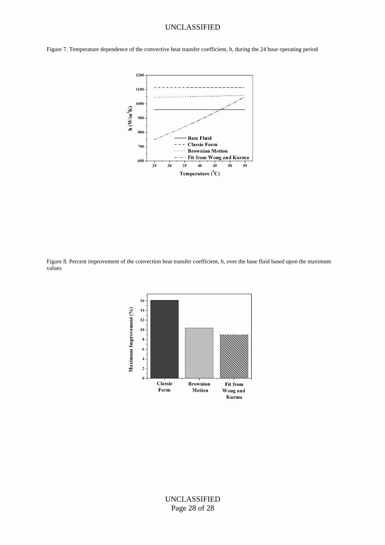
4.4 Thermal Protection – Enhancement of the Convective Heat Transfer Coefficient
The convective heat transfer coefficient has been significantly enhanced by the
utilization of nanofluids. Figure 7 shows the temperature dependent profile of the convective
heat transfer coefficient for each nanofluid model. All models offered a large improvement
over the base fluid (water) model, especially as the temperature increased. Figure 8 displays
the maximum percentage increase of the convective heat transfer coefficient, h, in
comparison to the base fluid (water) for each model. From these two figures and Table 2, the
heat transfer coefficient can be enhanced by up to 16.1%, demonstrating that augmenting
ordinary cooling fluids with nanoparticles can be extremely advantageous in many thermal
protection applications.
As noted earlier, however, the limitation of peak computer chip temperature seems to
remain relatively unchanged, even with increased convective heat transfer coefficients. This
occurrence can be explained by two possible factors. First, the contact area between the
coolant rail and the computer is quite small due to the enclosure restraints for this application.
Therefore, an enhancement in the convective heat transfer coefficient would be less
noticeable given the small contact area. Second, for the given system heat input and fixed
contact area, the temperature difference between the fluid and the computer is already quite
small (refer to Table 2). Therefore, a 16.1% increase in the convective heat transfer
coefficient will only translate into a 16.1% decrease in the temperature difference. In this
system, this translates into a small change in the peak computer chip temperature. Therefore,
for this application where the solution is insensitive to the model chosen, the Classic Model
would be preferred for its simplicity. However, if the system heat input increases, then the
UNCLASSIFIED
UNCLASSIFIED
Page 16 of 28
advantages of using nanofluids in the coolant system would become more evident. Also, the
contact area between the nanofluid and the computer chip assembly may be decreased in
order to further decrease the footprint of the cooling system in confined spaces. Therefore,
while the peak computer chip temperature is only slight decreased by the use of nanofluids,
the increase observed in the convective heat transfer coefficient demonstrates the unique
advantages of nanofluids.
5 Summary
The demanding cooling issues in vehicular electronic payloads such as those used in
military ground vehicles have been addressed by augmenting a thermoelectric cooling system
with nanofluids in a configuration which maximizes packaging flexibility and cooling
effectiveness. Since nanofluid modeling remains an unresolved research topic, three
nanofluid models were chosen and compared to a base cooling fluid (water) to determine the
significance of the particular nanofluid model utilized and the overall effectiveness of the
nanofluids compared with the base fluid. When simulated for desert operating conditions, the
system showed favorable cooling performance; however, there was little change in the peak
computer chip temperature when using nanofluids as opposed to the base fluid. Despite the
significantly increased convective heat transfer coefficient (up to 16.1%) for nanofluids, the
effect is minimized by small contact area in the heat sinks and small heat input. Additionally,
the various nanofluid models showed little difference (< 0.4%) in peak temperature,
demonstrating insensitivity to the chosen nanofluid model. Due to the increase in the heating
demands of modern electronic devices, these findings should be of particular interest in the
augmentation of current heat transfer strategies.
UNCLASSIFIED
UNCLASSIFIED
Page 17 of 28
References
Batchelor, G.K. (1977) 'Effect of Brownian-motion on bulk stress in a suspension of
spherical-particles', Journal of Fluid Mechanics, Vol. 83, pp. 97-117.
Baumann, J. (2006) 'Modeling and sizing a thermoelectric cooler within a thermal analyzer'.
Paper presented at the Annual Spacecraft Thermal Control Workshop. Mar. 2006. El
Segundo, CA.
Chandrasekar, M. and Suresh, S. (2009) 'A review on the mechanisms of heat transport in
nanofluids', Heat Transfer Engineering, Vol. 30, No. 14, pp. 1136-1150.
Chang, Y.W., Chang, C.C., Ke, M.T. and Chen, S.L. (2009) 'Thermoelectric air-cooling
module for electronic devices', Applied Thermal Engineering, Vol. 29, No. 13, pp.
2731-2737.
Choi, S.U.S. (2009) 'Nanofluids: From Vision to Reality Through Research', Journal of Heat
Transfer-Transactions of the ASME, Vol. 131, No. 3, pp. 033106-1-033106-9.
Dai, Y.J., Wang, R.Z. and Ni, L. (2003) 'Experimental investigation and analysis on a
thermoelectric refrigerator driven by solar cells', Solar Energy Materials and Solar
Cells, Vol. 77, No. 4, pp. 377-391.
Duangthongsuk, W. and Wongwises, S. (2009) 'Measurement of temperature-dependent
thermal conductivity and viscosity of TiO2-water nanofluids', Experimental Thermal
and Fluid Science, Vol. 33, No. 4, pp. 706-714.
Ellsworth, M.J., Campbell, L.A., Simons, R.E. and Iyengar, R.S.S. (2008) 'The evolution of
water cooling for IBM large server systems: Back to the future'. Paper presented at the
Intersociety Conference on Thermal and Thermomechanical Phenomena in Electronic
Systems, ITHERM. May 28-31, 2008. Orlando, FL.
UNCLASSIFIED
UNCLASSIFIED
Page 18 of 28
Finn, J., Ewing, D.J., Ma, L. and Wagner, J. (2010) 'Thermal protection of vehicle payloads
using phase change materials and liquid cooling'. Paper presented at the 2010
American Controls Conference. Jun. 30-Jul. 2, 2010. Baltimore, MD.
Godson, L., Raja, B., Lal, D.M. and Wongwises, S. (2010) 'Enhancement of heat transfer
using nanofluids-An overview', Renewable & Sustainable Energy Reviews, Vol. 14, No.
2, pp. 629-641.
Huang, H.S., Weng, Y.C., Chang, Y.W., Chen, S.L. and Ke, M.T. (2010) 'Thermoelectric
water-cooling device applied to electronic equipment', International Communications in
Heat and Mass Transfer, Vol. 37, No. 2, pp. 140-146.
Incropera, F.P. and DeWitt, D.P. (1990) Introduction to Heat Transfer, New York: John
Wiley & Sons.
Kakac, S. and Pramuanjaroenkij, A. (2009) 'Review of convective heat transfer enhancement
with nanofluids', International Journal of Heat and Mass Transfer, Vol. 52, No. 13-14,
pp. 3187-3196.
Leong, K.Y., Saidur, R., Kazi, S.N. and Mamun, A.H. (2010) 'Performance investigation of
an automotive car radiator operated with nanofluid-based coolants (nanofluid as a
coolant in a radiator)', Applied Thermal Engineering, Vol. 30, No. 17-18, pp. 2685-
2692.
Lertsatitthanakorn, C., Hirunlabh, J., Khedari, J. and Scherrer, J. (2001) 'Cooling
performance of free convected thermoelectric air conditioner'. Paper presented at the
20th International Conference on Thermoelectrics. June 8, 2001. Beijing, China.
Mitchell, T., Salah, M., Wagner, J. and Dawson, D. (2009) 'Automotive thermostat valve
configurations: enhanced warm-up performance', Journal of Dynamic Systems
UNCLASSIFIED
UNCLASSIFIED
Page 19 of 28
Measurement and Control-Transactions of the ASME, Vol. 131, No. 4, pp. 044501-1-
044501-7.
Nguyen, C.T., Desgranges, F., Galanisc, N., Roy, G., Mare, T., Boucher, S. and Mintsa, H.A.
(2008) 'Viscosity data for Al2O3-water nanofluid-hysteresis: is heat transfer
enhancement using nanofluids reliable?' International Journal of Thermal Sciences,
Vol. 47, No. 2, pp. 103-111.
Nguyen, C.T., Roy, G., Gauthier, C. and Galanis, N. (2007) 'Heat transfer enhancement using
Al2O3-water nanofluid for an electronic liquid cooling system', Applied Thermal
Engineering, Vol. 27, No. 8-9, pp. 1501-1506.
Pfahnl, A. and Liang, H. (2004) 'Liquid cooling high power compact electronics'. Paper
presented at the Ninth Intersociety Conference on Thermal and Thermomechanical
Phenomena in Electronic Systems. June 1-4, 2004. Las Vegas, NV.
Prasher, R., Bhattacharya, P. and Phelan, P.E. (2005) 'Thermal conductivity of nanoscale
colloidal solutions (nanofluids)', Physical Review Letters, Vol. 94, No. 2, pp. 025901-1-
025901-4.
Riffat, S.B. and Ma, X.L. (2003) 'Thermoelectrics: a review of present and potential
applications', Applied Thermal Engineering, Vol. 23, No. 8, pp. 913-935.
Robinson, A.J. (2009) 'A thermal-hydraulic comparison of liquid microchannel and
impinging liquid jet array heat sinks for high-power electronics cooling', IEEE
Transactions on Components and Packaging Technologies, Vol. 32, No. 2, pp. 347-
357.
Simons, R.E. and Chu, R.C. (2000) 'Application of thermoelectric cooling to electronic
equipment: A review and analysis'. Paper presented at the Sixteenth Annual IEEE
UNCLASSIFIED
UNCLASSIFIED
Page 20 of 28
Semiconductor Thermal Measurement and Management Symposium. Mar. 21-23, 2000.
San Jose, CA.
Simons, R.E., Ellsworth, M.J. and Chu, R.C. (2005) 'An assessment of module cooling
enhancement with thermoelectric coolers', Journal of Heat Transfer-Transactions of the
Asme, Vol. 127, No. 1, pp. 76-84.
Tan, S., Tok, K., Chai, J. and Pinjala, D. (2007) 'Thermal characterization and liquid cooling
system integration for stacked modules'. Paper presented at the 9th Electronics
Packaging Technology Conference. Dec. 10-12, 2007. Singapore.
Wang, J., Zou, K. and Friend, J. (2009) 'Minimum power loss control—thermoelectric
technology in power electronics cooling'. Paper presented at the 2009 Energy
Conversion Congress and Exposition. Sept. 20-24, 2009. San Jose, CA.
Wang, X.Q. and Mujumdar, A.S. (2007) 'Heat transfer characteristics of nanofluids: a
review', International Journal of Thermal Sciences, Vol. 46, No. 1, pp. 1-19.
Wong, K.F.V. and Kurma, T. (2008) 'Transport properties of alumina nanofluids',
Nanotechnology, Vol. 19, No. 34, pp. 345072-1-345072-8.
Wong, K.V. and Castillo, M.J. (2010) 'Heat transfer mechanisms and clustering in
nanofluids', Advances in Mechanical Engineering, Vol. 14, No. 2, pp. 629-641.
UNCLASSIFIED
UNCLASSIFIED
Page 21 of 28
APPENDIX: NOMENCLATURE LIST
A area, [m2], state space variable matrix, fitting parameter
B state space input matrix
C heat capacity, [J/K]
cp specific heat, [J/kg K]
D diameter of pipe, [m]
d nanoparticle diameter, [nm]
h convective heat transfer coefficient, [W/m2 K]
i current, [A]
k conductive heat transfer coefficient, [W/m K]
kb Boltzmann constant, [J/K]
m fitting parameter
n number of temperature nodes, number of thermoelectric couples
Nu Nusselt number
P power, [W]
Pr Prandtl number
Q heat rate, [W]
R thermal resistance, [K/W]
Rb interfacial thermal resistance, [Km2/W]
Re Reynolds number
T temperature, [ºC]
V velocity, [m/s], voltage, [V]
v velocity, [m/s]
u state input vector
x state variable vector
t time step, [s]
Seebeck coefficient, [μV/K], fluid interfacial parameter
dynamic viscosity, [Pa s]
kinematic viscosity, [m2/s]
volume fraction of nanoparticles
density, [kg/m3]
Subscripts
Al aluminum
avg average
C computer chip, cold side
cold cold side
UNCLASSIFIED
UNCLASSIFIED
Page 22 of 28
cool coolant
D diameter of pipe [m]
eff effective
f base fluid
H hot side
high upper thermostat bound
hot hot side
i node
in inner loop
low lower thermostat bound
N nanoparticle
out outer loop
p nanoparticle
TEC thermoelectric module
w water
UNCLASSIFIED
UNCLASSIFIED
Page 23 of 28
Tables
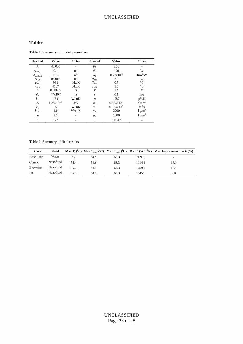
Table 1. Summary of model parameters
Symbol Value Units Symbol Value Units
A 40,000 - Pr 3.56 -
Acool,in 0.1 m2 100 W
Acool,out 0.3 m2 Rb 0.77x10⁻⁸ Km2/W
ATEC 0.0016 m2 RTEC 2.0 Ω
cpAl 963 J/kgK Tlow 0.5 °C
cpw 4187 J/kgK Thigh 1.5 °C
d 0.00635 m V 12 V
dN 47x10-9 m v 0.1 m/s
kAl 180 W/mK α -287 μV/K
kb 1.38x10⁻²³ J/K μw 0.653x10⁻³ Ns/ m2
kw 0.58 W/mK νw 0.653x10⁻⁶ m2/s
kTEC 1.0 W/m2K ρAl 2700 kg/m3
m 2.5 - ρw 1000 kg/m3
n 127 - 0.0847 -
Table 2. Summary of final results
Case Fluid Max Tc (0C) Max Tinner (
0C) Max Touter (0C) Max h (W/m2K) Max Improvement in h (%)
Base Fluid Water 57 54.9 68.3 959.5 -
Classic Nanofluid 56.4 54.6 68.3 1114.1 16.1
Brownian Nanofluid 56.6 54.7 68.3 1059.2 10.4
Fit Nanofluid 56.6 54.7 68.3 1045.9 9.0
CQ
UNCLASSIFIED
UNCLASSIFIED
Page 24 of 28
Figure Captions
Figure 1. Size distribution of proposed nanoparticles as ascertained from Transmission
Electron Microscope (TEM) pictures
Figure 2. Schematic of thermoelectric concept for heat transfer between the cold and hot
device surfaces
Figure 3. Schematic of the vehicle electronic thermal management system design featuring
computer chips, thermoelectric devices, and heat exchangers
Figure 4. Computer heat load for a 24 hour cycle in desert conditions
Figure 5. Algorithm flow chart
Figure 6. Computer chip temperature response, TC, for the 24 hour operating period
Figure 7. Temperature dependence of the convective heat transfer coefficient, h, during the
24 hour operating period
Figure 8. Percent improvement of the convection heat transfer coefficient, h, over the base
fluid based upon the maximum values
UNCLASSIFIED
UNCLASSIFIED
Page 25 of 28
Figures
Figure 1. Size distribution of proposed nanoparticles as ascertained from Transmission Electron Microscope (TEM) pictures
Figure 2. Schematic of thermoelectric concept for heat transfer between the cold and hot device surfaces
UNCLASSIFIED
UNCLASSIFIED
Page 26 of 28
Figure 3. Schematic of the vehicle electronic thermal management system design featuring computer chips, thermoelectric
devices, and heat exchangers
Figure 4. Computer heat load for a 24 hour cycle in desert conditions
UNCLASSIFIED
UNCLASSIFIED
Page 27 of 28
Figure 5. Algorithm flow chart
Figure 6. Computer chip temperature response, TC, for the 24 hour operating period
UNCLASSIFIED
UNCLASSIFIED
Page 28 of 28
Figure 7. Temperature dependence of the convective heat transfer coefficient, h, during the 24 hour operating period
Figure 8. Percent improvement of the convection heat transfer coefficient, h, over the base fluid based upon the maximum
values