Embed Size (px)
Citation preview

November 2017 Altera Corporation
AN-659-1.3
© 2017 Altera Corporation. AlQUARTUS and STRATIX worOffice and in other countries. respective holders as describedproducts to current specificatioproducts and services at any tiof any information, product, oadvised to obtain the latest verfor products or services.
101 Innovation DriveSan Jose, CA 95134www.altera.com
Thermal Management and MechanicalHandling for Lidless Flip Chip Ball-Grid
Array
Application NoteThis application note provides guidance on thermal management and mechanical handling of lidless flip chip ball-grid array (FCBGA) for Altera® devices.
This application note includes the following sections:
■ “Lidless FCBGA Overview”
■ “General Properties of Thermal Interface Materials”
■ “Attaching Heat-Sinks” on page 4
■ “Device Reworkability” on page 12
■ “Handling and Transfer for Lidless FCBGA” on page 13
■ “Vendors List” on page 14
Lidless FCBGA OverviewLidless FCBGA packages maximize PCB real estate by allowing closer spacing between passive components and the flip chip die. Lidless FCBGA packages enable the die to contact with an external heat sink, ensuring the thinnest band line and best thermal impedance between the flip chip die and the attached heat sink.
Altera produces the lidless FCBGA package in an exposed die configuration. This configuration maintains the excellent thermal performance of bare die for the lidless FCBGA and provides a support surface around the bare die for a direct heat-sink attachment.
Figure 1 shows the cross section of the lidless FCBGA.
Figure 1. Cross Section of the Lidless FCBGA
Solder Ball
Underfill
Laminate Substrate
Die
l rights reserved. ALTERA, ARRIA, CYCLONE, HARDCOPY, MAX, MEGACORE, NIOS, ds and logos are trademarks of Altera Corporation and registered in the U.S. Patent and Trademark All other words and logos identified as trademarks or service marks are the property of their
at www.altera.com/common/legal.html. Altera warrants performance of its semiconductor ns in accordance with Altera's standard warranty, but reserves the right to make changes to any
me without notice. Altera assumes no responsibility or liability arising out of the application or use r service described herein except as expressly agreed to in writing by Altera. Altera customers are sion of device specifications before relying on any published information and before placing orders
Feedback Subscribe
ISO 9001:2008 Registered

Page 2 General Properties of Thermal Interface Materials
The coplanarity specification limits for lidless FCBGA less than or equal to 35 mm x 35 mm: 8 mils (0.20 mm). Table 1 lists an example of the coplanarity data measured from production of an Arria II GX EP2AGX260 device in F1152 package.
General Properties of Thermal Interface Materials Altera recommends considering the suitable thermal interface material (TIM) type early in your design. TIMs can be the limiting factors in the expense of thermal management designs. You can use TIM effectively to help reduce the size of the heat sinks and the need for larger cooling fans. The extended benefit of an effective TIM is a solution that is faster, easier to apply, and less costly than changing heat sinks or redesigning a chassis.
Table 2 lists the types of TIM and their advantages and disadvantages.
Table 1. Coplanarity Data
Yield Min (mil) Max (mil)
Average (mil) Std Dev Std Dev + 3 Cpk
100% 4.74 6.71 5.73 0.40 6.93 1.89
Table 2. TIM Type Advantage and Disadvantage (Part 1 of 2)
TIM Type Description Advantage Disadvantage
Thermally Conductive Adhesive or Epoxy
■ Thermally conductive adhesive is silicone-based formulation that contain filler. Thermally conductive adhesive offers a superior mechanical bond.
■ Epoxy is particle-laden, one-or two-component materials that you can apply through dispensing or stencil printing.
■ Provides structural support, eliminating the need for mechanical clamping.
■ Cured to allow for cross-linking of the polymer, which provides the adhesive property.
■ May not provide sufficient bond strength because of the small contact area.
■ The relative high impedance might affect the thermal performance significantly.
■ Device rework is very difficult and may result in damaging the device.
Thermal Tape
Filled pressure sensitive adhesives (PSAs) coated on a support matrix such as polyimide film, fiberglass mat, or aluminum foil.
■ Convenient for heat-sink attachment with mid-range thermal performance.
■ Does not require mechanical clamping.
■ Works best on flat surfaces.
■ Plastic ICs are usually concave in the center, and heat-sink surfaces may vary. This unevenness can result in air gaps in the interface.
■ May not provide sufficient bond strength without the help of mechanical attachment, causing the heat sink to fall off.
■ Device rework is very difficult and may result in damaging the device.
■ Heat sinks may come off over time because of the heat and weight of the heat sinks for vertically-mounted PCBs.
Thermal Management and Mechanical Handling for Lidless Flip Chip Ball-Grid Array November 2017 Altera Corporation

General Properties of Thermal Interface Materials Page 3
Recommended TIMsTable 3 lists the TIMs recommended by Altera TIM vendors. Factors such as gap-filling capability, conductivity of materials, compatibility with molding compound, and ease of use determine the typical application recommendations.
Thermal Grease
Contains silicone oil loaded with thermally conductive filler.
■ Low thermal resistance.
■ Does not require curing.
■ Flows and conforms to surfaces.
■ Offers a reworkable thermal interface layer.
■ Requires mechanical clamping.
■ Messy and difficult to apply because of its high viscosity.
■ Can degrade, pump-out, or dry out during extended operation and over time, causing the thermal performance of the TIM to suffer significantly.
Thermal Gel Low modulus, paste-like material that is lightly cross-linked.
■ Low thermal resistance.
■ Conforms to surfaces, while displaying reduced material pump-out.
Requires mechanical clamping.
Thermal Pad
■ Fabricated by molding non-reinforced silicone with conductive fillers.
■ Reinforcements for thermal pads include woven glass, metal foils, and polymer films.
■ Pre-cut.
■ Offers gap-filling functionality.
■ Requires mechanical clamping.
■ Limited thermal performance.
■ Sensitive to pressure.
Phase Change Material (PCM)
Undergoes a transition from a solid to a semi-solid phase with the application of heat and pressure. The material is in a liquid phase at die-operating conditions.
■ Low thermal resistance.
■ Able to conform to mating surfaces.
■ Does not require curing
■ Requires mechanical clamping.
■ Rework is difficult.
Table 2. TIM Type Advantage and Disadvantage (Part 2 of 2)
TIM Type Description Advantage Disadvantage
Table 3. TIMs Recommended for the Lidless FCBGA Package (Part 1 of 2)
Vendor Product Type Conductivity Format Typical Application
Laird Technologies Tpcm 780 Phase change 5.5 W/m°K Pad Desktop and laptop PCs
Laird Technologies Tpcm 780SP Phase change 5.5 W/m°K Liquid Desktop and laptop PCs
Laird Technologies Tpcm 580 Phase change 3.8 W/m°K Pad CPUs, custom ASIC, and GPUs
Laird Technologies Tgrease 980 Thermal grease 3.8 W/m°K Grease CPUs, custom ASIC, and GPUs
Laird Technologies Tgrease 880 Thermal grease 3.1 W/m°K Grease CPUs, custom ASIC, and GPUs
Laird Technologies Tgrease 2500 Thermal grease 3.8 W/m°K Paste High-performance CPUs and
GPUs
Bergquist 3500S35 Gap filler (2 parts) 3.6 W/m°K Pad PCBA to housing
Chomerics T777 Phase change 3.5 W/m°K Pad CPUs, GPUs, and chipsets
Chomerics 976 Gap filler 3.0 W/m°K Pad CPUs, GPUs, and chipsets
Chomerics 579 Gap filler 1.5 W/m°K Pad CPUs, GPUs, and chipsets
Thermal Management and Mechanical Handling for Lidless Flip Chip Ball-Grid Array November 2017 Altera Corporation

Page 4 Attaching Heat-Sinks
1 To prevent the die from chipping or cracking, ensure that the TIM is enough to cover the edges of the die when applying TIM to the heat sink and package.
Attaching Heat-SinksYou can attach a heat sink to a heat source in several ways. For efficient heat dissipation, you must consider the advantages and disadvantages of each heat sink attachment method.
When attaching a heat sink to a heat source with a small contact area such as the lidless FCBGA package, you must consider the following factors:
■ Possibility of the heat sink tipping or tilting
■ Possibility of damaging the exposed die during the heat sink installation
■ Contact area can be too small to form a strong bond with an adhesive or a tape attachment
Heat-Sink Attachment Methods You can use two types of heat-sinks attachment; mechanical and non-mechanical.
Table 4 lists the types of heat-sink attachments, typical attachment methods, advantage and disadvantage of the attachment methods and their suitability for lidless packages.
Chomerics T411 Thermal conductive tape 0.5 W/m°K Tape CPUs, GPUs, and chipsets
Laird Technologies T Flex HR600 Gap filler 3.0 W/m°K Pad Cooling to chassis, frames
Laird Technologies T Flex HR400 Gap filler 1.8 W/m°K Pad Cooling to chassis, frames
Table 3. TIMs Recommended for the Lidless FCBGA Package (Part 2 of 2)
Vendor Product Type Conductivity Format Typical Application
Thermal Management and Mechanical Handling for Lidless Flip Chip Ball-Grid Array November 2017 Altera Corporation

Attaching Heat-SinksPage
5
November 2017
Altera CorporationTherm
al Managem
ent and Mechanical Handling for Lidless Flip Chip Ball-Grid Array
Suitability for Lidless Package
■ Does not provide sufficient bond strength because of the small contact area.
■ May cause the heat sink to tip or tilt. For more information, refer to “Overcoming Heat Sink Tipping or Tilting for Small Heat Source and Lidless Packages” on page 9.
f
■ Does not provide sufficient bond strength because of the small contact area.
■ Not suitable for applications in which the PCB or heat sink is perpendicular to the ground, especially for lidless package.
■ May cause the heat sink to tip or tilt. For more information, refer to “Overcoming Heat Sink Tipping or Tilting for Small Heat Source and Lidless Packages” on page 9
Table 4. Advantage and Disadvantage for Each Attachment Method (Part 1 of 3)
Attachment Method Attachment Type Advantage Disadvantage or Risk
Epoxy or Thermally Conductive Adhesive
Non-Mechanical Requires no additional spaces on the PCB.
■ Harder to control the application process.
■ Rework is very difficult.
■ May damage the die.
■ For more information aboutthe risks, refer to “Non-Mechanical Heat-SinkAttachment Risks and Disadvantages” on page 8.
Thermal Tape
Non-Mechanical Requires no additional spaces on the PCB.
■ Relatively high impedance otape significantly affects thethermal performance.
■ For more information aboutthe risks, refer to “Non-Mechanical Heat-SinkAttachment Risks and Disadvantages” on page 8.
Epoxy or Thermally Conductive Adhesive

Page6
Attaching Heat-Sinks
Thermal M
anagement and M
echanical Handling for Lidless Flip Chip Ball-Grid Array Novem
ber 2017Altera Corporation
May cause the heat sink to tip or tilt. For more information, refer to “Overcoming Heat Sink Tipping or Tilting for Small Heat Source and Lidless Packages” on page 9
r
May cause the heat sink to tip or tilt. For more information, refer to “Overcoming Heat Sink Tipping or Tilting for Small Heat Source and Lidless Packages” on page 9
Suitability for Lidless Package
Z-Clip
Mechanical Attachment
Provides stable attachment to heat source and transfers load to mounting anchors or the PCB.
Requires additional space on the PCB for anchor locations; however, Z-clip requires lesserspace than other mechanical attachment types, such as pushpins and shoulder screws.
Talon Clip
Mechanical Attachment
Provides stable attachment to heat source and transfers load to mounting anchors or the PCB.
Requires additional space on the PCB for anchor locations; however, Talon-clip requires lesser space than other mechanical attachment types, such as push pins and shouldescrews.
Table 4. Advantage and Disadvantage for Each Attachment Method (Part 2 of 3)
Attachment Method Attachment Type Advantage Disadvantage or Risk

Attaching Heat-SinksPage
7
November 2017
Altera CorporationTherm
al Managem
ent and Mechanical Handling for Lidless Flip Chip Ball-Grid Array
.
May cause the heat sink to tip or tilt. For more information, refer to “Overcoming Heat Sink Tipping or Tilting for Small Heat Source and Lidless Packages” on page 9
May cause the heat sink to tip or tilt. For more information, refer to “Overcoming Heat Sink Tipping or Tilting for Small Heat Source and Lidless Packages” on page 9
Suitability for Lidless Package
Push Pin
Mechanical Attachment
■ Provides a stable attachment to a heat sink and transfers load to the PCB.
■ Allows for tight control over mounting force and load placed on chip and solder balls.
Requires additional space on the PCB for push pin locations
Shoulder Screw
Mechanical Attachment
■ Provides stable attachment to heat sink and transfers load to the PCB, backing plate, or chassis.
■ Suitable for high mass heat sinks.
■ Allows for tight control over mounting force and load placed on chip and solder balls.
Requires additional space on the PCB for shoulder screws locations.
Table 4. Advantage and Disadvantage for Each Attachment Method (Part 3 of 3)
Attachment Method Attachment Type Advantage Disadvantage or Risk

Page 8 Attaching Heat-Sinks
Non-Mechanical Heat-Sink Attachment Risks and DisadvantagesFigure 2 and Figure 3 show the risk of die damage and poor thermal performance due to uneven heat sink placement for non-mechanical heat-sink attachment.
With mechanical heat-sink attachments, the force on all sides of the heat sink is even, resulting in an even bond line thickness of the TIM and even dissipation of heat from the heat sink. Figure 4 shows the even compressive force on the heat-sink mount with mechanical attachment.
Figure 2. Die Damage
Figure 3. Uneven Bond Line Thickness of TIM
Figure 4. Mechanical Heat-Sink Attachment
PCB
Die Molding
Heat sink
Laminate Substrate
Damage
PCB
Die MoldingMolding
Heat sink
Laminate Substrate
Uneven TIM
Even force Even force
Die
Heat sinkTIM
Push pins
PCB
Laminate Substrate
Thermal Management and Mechanical Handling for Lidless Flip Chip Ball-Grid Array November 2017 Altera Corporation

Attaching Heat-Sinks Page 9
Designing Heat-Sink Attachment for Lidless FCBGA PackageWhen designing heat sink attachments for a lidless package, you must consider the height of the die above the substrate and also the height of decoupling capacitors (in some devices).
Figure 5 shows a cross-sectional view of a lidless FCBGA package (with optional capacitors).
f For more information about package information, refer to the Altera Device Package Information Data Sheet.
Overcoming Heat Sink Tipping or Tilting for Small Heat Source and Lidless PackagesWhen you attach a heat sink to a small heat source or a lidless package, the heat sink can tip or tilt; thus damaging the die. You can apply sponge pads (small compressible foam pads) to the heat sink to prevent the heat sink from tipping or tilting. The sponge pad helps to stabilize the heat sink during attachment. For heat sinks attachment on a lidless package, you must consider using compressible foam pads to prevent die chipping.
Figure 6 shows a type of sponge pad.
Figure 5. Cross-Sectional View of a Lidless FCBGA Package
Solder Ball
Underfill
Laminate Substrate
CapacitatorDieCapacitator
Figure 6. Sponge Pad
Thermal Management and Mechanical Handling for Lidless Flip Chip Ball-Grid Array November 2017 Altera Corporation
Page 10 Attaching Heat-Sinks
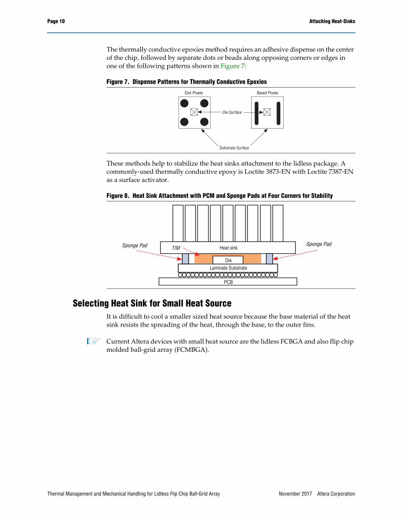
The thermally conductive epoxies method requires an adhesive dispense on the center of the chip, followed by separate dots or beads along opposing corners or edges in one of the following patterns shown in Figure 7:
These methods help to stabilize the heat sinks attachment to the lidless package. A commonly-used thermally conductive epoxy is Loctite 3873-EN with Loctite 7387-EN as a surface activator.
Selecting Heat Sink for Small Heat SourceIt is difficult to cool a smaller sized heat source because the base material of the heat sink resists the spreading of the heat, through the base, to the outer fins.
1 Current Altera devices with small heat source are the lidless FCBGA and also flip chip molded ball-grid array (FCMBGA).
Figure 7. Dispense Patterns for Thermally Conductive Epoxies
Figure 8. Heat Sink Attachment with PCM and Sponge Pads at Four Corners for Stability
Die Surface
Substrate Surface
Dot Posts Bead Posts
Laminate SubstrateDie
Heat sinkTIM
PCB
Sponge PadSponge Pad
Thermal Management and Mechanical Handling for Lidless Flip Chip Ball-Grid Array November 2017 Altera Corporation

Attaching Heat-Sinks Page 11
Figure 9 shows an aluminum heat sink and a small heat source.
To spread the heat from a small heat source to the entire base, some vendors offer efficient and reliable copper embedded heat sinks.
Figure 10 shows a copper embedded heat sink.
Compression During Heat Sink Attachments■ Altera’s recommendation for constant compressive load on the packages with
eutectic SnPb balls:
■ 3g per solder ball for 0.5mm pitch MBGA package
■ 6g per solder ball for 0.8mm pitch UBGA package
■ 8g per solder ball for 1mm pitch FBGA package
■ 12g per solder ball for 1.27mm pitch BGA package
■ For SAC solder balls, customers can use the following constant compressive loads in use:
■ 7g per solder ball for 0.5mm pitch MBGA package
■ 12g per solder ball for 0.8mm pitch UBGA package
■ 16g per solder ball for 1mm pitch FBGA package
■ 24g per solder ball for 1.27mm pitch BGA package
Figure 9. Aluminum Heat Sink
Figure 10. Copper Embedded Heat Sink
Aluminum Heat Sink
Small Heat Source
Aluminum Heat Sink
Small Heat SourceCopper Heat Spreader
Thermal Management and Mechanical Handling for Lidless Flip Chip Ball-Grid Array November 2017 Altera Corporation

Page 12 Device Reworkability
■ For heat-sink application, Altera’s recommendation is to not exceed 20g load per solder ball.
■ Typical TIM2 vendor recommendation is to apply a 50 psi load during TIM2 curing
Device ReworkabilityTable 5 lists the reworkability of different combinations of heat sinks and TIMs.
Although non-mechanical heat sink attachment requires less PCB space, you must consider the possibility of damaging the device or PCB during rework. However, reworking the heat sink with mechanical heat sink attachment is very straight forward and easy.
Reworking or Removing Heat Sinks To remove a heat sink attached with a thermal conductive tape or epoxy, follow these steps:
1. Soak the device in isopropyl alcohol for 45 minutes to soften the TIM.
2. Carefully insert the edge of a razor blade into the TIM bond line between the heat sink and the device.
3. Slowly twist the blade to exert upward pressure on the package while moving the blade inward as the heat sink begins to separate.
4. Check for die edge damage.
To remove a heat sink attached with PCM or thermal gap filler, follow these steps:
1. Remove the push pins or clips that hold the mechanical attached heat sink.
2. Insert a single-edge razor blade into the TIM bond line between the heat sink and the component.
3. Slowly twist the blade forward with an upward tilt force to separate the heat sink and the component.
Table 5. Heat Sink and TIM Reworkability
Heat Sink Types TIM Type Application Rework
Non Mechanical Attachment
■ Thermally Conductive Adhesive
■ Epoxy
Difficult to control the bond line thickness. May not have optimal thermal performance.
High risk of damaging the device or PCB.
Thermal tape Must be larger than die size. Need sponge pads for stability. May not have optimal thermal performance.
High risk of damaging the device or PCB.
Mechanical Attachment
PCM Pre-cut to size. Need sponge pads for stability. Good thermal performance Easy to remove.
Gap filler Pre-cut to size. Conform to contour of the device. May not have optimal thermal performance Easy to remove.
Thermal grease High performance. Conform to contour of the device. Pump-out concerns. Easy to remove.
Thermal Management and Mechanical Handling for Lidless Flip Chip Ball-Grid Array November 2017 Altera Corporation
Handling and Transfer for Lidless FCBGA Page 13
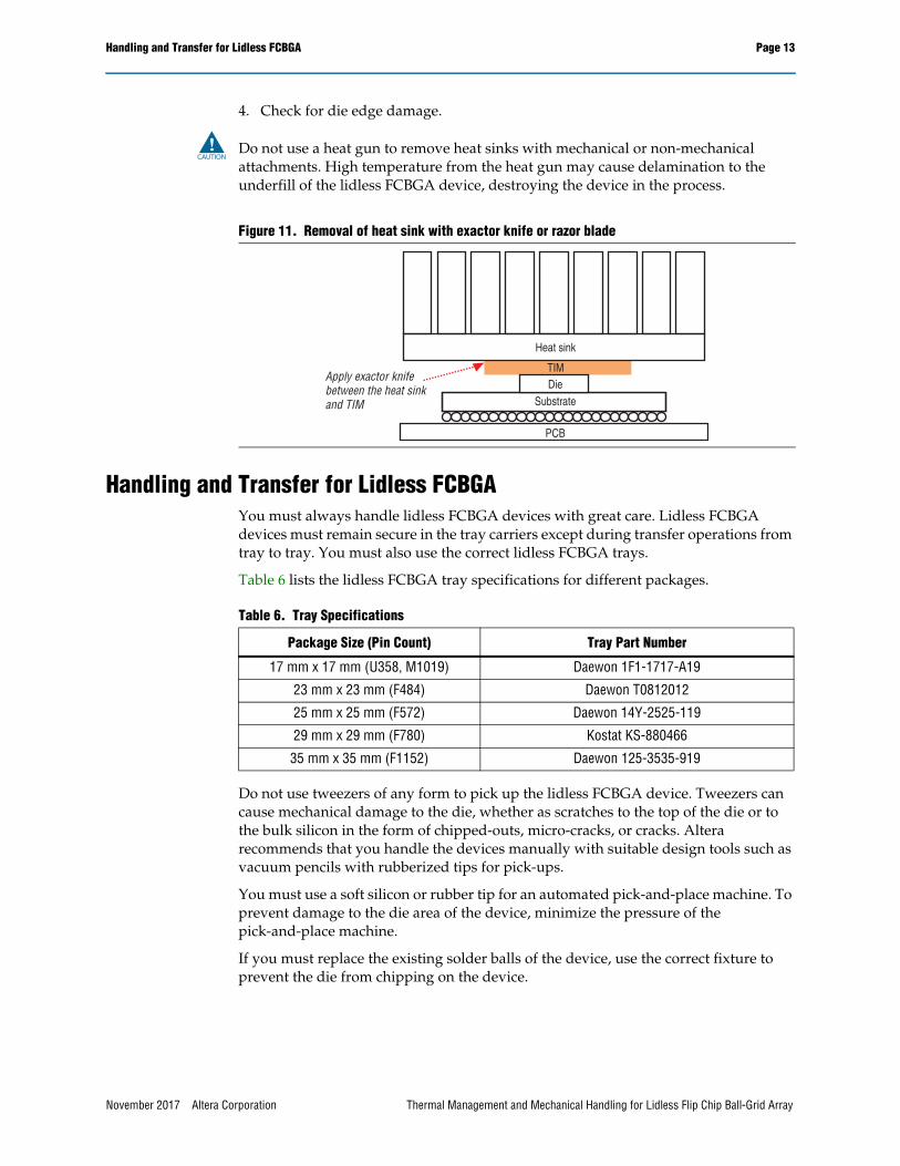
4. Check for die edge damage.
c Do not use a heat gun to remove heat sinks with mechanical or non-mechanical attachments. High temperature from the heat gun may cause delamination to the underfill of the lidless FCBGA device, destroying the device in the process.
Handling and Transfer for Lidless FCBGAYou must always handle lidless FCBGA devices with great care. Lidless FCBGA devices must remain secure in the tray carriers except during transfer operations from tray to tray. You must also use the correct lidless FCBGA trays.
Table 6 lists the lidless FCBGA tray specifications for different packages.
Do not use tweezers of any form to pick up the lidless FCBGA device. Tweezers can cause mechanical damage to the die, whether as scratches to the top of the die or to the bulk silicon in the form of chipped-outs, micro-cracks, or cracks. Altera recommends that you handle the devices manually with suitable design tools such as vacuum pencils with rubberized tips for pick-ups.
You must use a soft silicon or rubber tip for an automated pick-and-place machine. To prevent damage to the die area of the device, minimize the pressure of the pick-and-place machine.
If you must replace the existing solder balls of the device, use the correct fixture to prevent the die from chipping on the device.
Figure 11. Removal of heat sink with exactor knife or razor blade
SubstrateDie
Heat sink
TIM
PCB
Apply exactor knife between the heat sink and TIM
Table 6. Tray Specifications
Package Size (Pin Count) Tray Part Number
17 mm x 17 mm (U358, M1019) Daewon 1F1-1717-A19
23 mm x 23 mm (F484) Daewon T0812012
25 mm x 25 mm (F572) Daewon 14Y-2525-119
29 mm x 29 mm (F780) Kostat KS-880466
35 mm x 35 mm (F1152) Daewon 125-3535-919
Thermal Management and Mechanical Handling for Lidless Flip Chip Ball-Grid Array November 2017 Altera Corporation

Page 14 Vendors List
Vendors ListThe following list contains recommended TIM vendors:
■ Laird Technologies(www.lairdtech.com)
■ Chomerics (www.chomerics.com)
■ The Bergquist Company (www.bergquistcompany.com)
■ 3M (www.3m.com)
■ ShinEtsu MicroSi (www.microsi.com)
The following list contains recommended heat sink vendors:
■ Alpha Company (www.alphanovatech.com)
■ Malico (www.malico.com.tw)
■ Aavid Thermalloy (www.aavidthermalloy.com)
■ Radian Heatsinks (www.radianheatsinks.com)
The following list contains recommended FCMBGA tray vendors:
■ Daewon (www.daewonspic.com)
■ Kostat (www.kostat.com)
Document Revision HistoryTable 7 lists the revision history for this document.
Table 7. Document Revision History
Date Version Changes
November 2017 1.3 Added recommendations for new packages in the Compression During Heat Sink Attachments section.
June 2016 1.2 Updated the Compression During Heat Sink Attachments section.
August 2014 1.1 Updated the Compression During Heat Sink Attachments section.
March 2012 1.0 Initial release.
Thermal Management and Mechanical Handling for Lidless Flip Chip Ball-Grid Array November 2017 Altera Corporation