Embed Size (px)
Citation preview
wwwh-baucom
for superior solutions
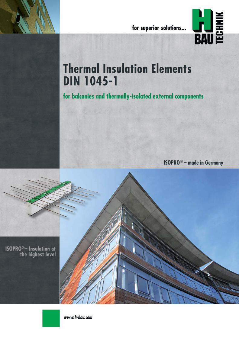
Thermal Insulation ElementsDIN 1045-1for balconies and thermally-isolated external components
ISOPROregndash Insulation atthe highest level
ISOPROreg ndash made in Germany
wwwh-baucom2
Markircher Straszlige 1468229 MannheimTel 06 21 4 84 03 40Fax 06 21 4 84 03 44eMail mannheimjp-bautechnikde
Houmllderlinstraszlige 2375446 Wiernsheim StuttgartTel 0 70 41 86 08 58Fax 0 70 41 22 39eMail stuttgartjp-bautechnikde
Fundlandstraszlige 2945326 EssenTel 02 01 28 96 60Fax 02 01 28 96 620eMail essenjp-bautechnikde
Oeseder Straszlige 11549124 Georgsmarienhuumltte b OsnabruumlckTel 0 54 01 78 15 44Fax 0 54 01 78 15 40eMail osnabrueckjp-bautechnikde
Stettiner Straszlige 2030916 Isernhagen HannoverTel 05 11 6 17 79Fax 05 11 61 46 04eMail hannoverjp-bautechnikde
Nobelstraszlige 51-5512057 BerlinTel 0 30 6 82 83-02Fax 0 30 6 82 83-4 99eMail berlinjp-bautechnikde
Zum Wiesengrund 201723 Kesselsdorf DresdenTel 03 52 04 2 15 11Fax 03 52 04 2 15 18eMail dresdenjp-bautechnikde
Lechstraszlige 2190451 NuumlrnbergTel 09 11 6 42 78 08Fax 09 11 6 42 84 72eMail nuernbergjp-bautechnikde
Dr-Karl-Lenz-Straszlige 6687700 MemmingenTel 0 83 31 93 72 20Fax 0 83 31 93 73 42eMail memmingenjp-bautechnikde
H-BAU Technik GmbHAm Guumlterbahnhof 2079771 KlettgauTel 0 77 42 92 15-20Fax 0 77 42 92 15-90eMail infoklettgauh-baude
wwwh-baucomwwwjp-bautechnikde
Produktion und Auslieferung Nord-OstBrandenburger Straszlige14641 WachowTel 03 32 39 7 75-20Fax 03 32 39 7 75-90eMail infoberlinh-baude
Sales of our products in Germany are handledexclusively by JampP Bautechnik Vetriebs-GmbHthrough their 10 regional offices You can alsocontact our head office in Klettgau
Locations of our branch offices
for superior solutions
1
ISOPROreg
Balcony insulation elements
Contents
ISOPROreg Thermal insulation elementsGeneral Technical principles 2
Building physics ndash Heat insulation 3-7Building physics ndash Fire protection 8Exposition class 9
Isoproreg Overview of types 10-11Order codes and installation positions 12
Type IP-IPT Examples 13Construction and dimensions 14-15Dimensioning table 16-17On-site reinforcement and installation instructions 18-19Special types 20-21Deflection and height offset 22-23Expansion joint spacing 24Two-part elements 25-26
Type IPT-Corner Construction and dimensionsDimensioning table 27-28On-site reinforcement 29
Type IPQ-IPQS Examples of transverse force elements 31Construction and dimensionsDimensioning table 32-35On-site reinforcement 33
Type IPQQ-IPQQS Construction and dimensionsDimensioning table 36-39On-site reinforcement 37
Type IPTD Construction and dimensions 40On-site reinforcement 41Dimensioning table 42-43
Type IPQZ Construction and dimensionsDimensioning table 44On-site reinforcement 45
Type IPH Construction and dimensions 46On-site reinforcement 47
Type IPA Construction and dimensional values 48On-site reinforcement and installation instructions 49
Type IPF Construction and dimensional values 50On-site reinforcement and installation instructions 51
Type IPO Construction and dimensional values 52On-site reinforcement and installation instructions 53
Type IPS Construction and dimensional values 54On-site reinforcement and installation instructions 55
Type IPW Construction and dimensional values 56On-site reinforcement and installation instructions 57
Approval 58Tender 59
ISOPROreg - Insulation at the highest level
The constructionISOPROreg is a thermally insulatingsupporting connection element be-tween concrete construction compo-nents Its excellent thermal insulationproperties provide a reliable solutionto the problems of building physicsat the interface between externaland internal construction elementsISOPROreg consists of an insulationbody together with a static rodframework which ensures effectivetransfer of static forces
Insulation materialThe insulation body is 80 mm thickThe material used is EPS (WLG 035)
FrameworkThe integral reinforcement rods aremade from BST 500 in the area ofthe insulation and up to 10 cm to theside from BST 500 NR Elementsmade from high-performance spe-cialty concrete are predominantlyused in the compression zone
This eliminates any potential corro-sion problems and provides optimalabsorption of transverse forces andbending moments
QualityThe consistently high quality stan-dard of ISOPROreg is maintained bycontinual in-house and third-partymonitoring
Applications FeaturesThe compact and easy-to-handleISOPROreg elements are deliveredready for rapid problem-free instal-lation
SafetyThe arrow indicator is always at thetop and points in the direction of thebalcony slab to be connected The el-ement identification together withinformation on the concrete coveringand height of the element is also in-dicated on each elementThe ISOPROreg elements are simplyconnected by overlapping with theon-site reinforcement (in accordancewith structural specifications)
Projecting balcony with ISOPROreg type IP
Thermod
aumlmm
Thermod
aumlmm
Balkon
seite
Balkon
seite
Projecting balcony with ISOPROreg type IPT
Projecting balcony with ISOPROreg type IPQ
ISOPROreg
Technical principles
wwwh-baucom2
Thermal bridgeIn the construction of buildings un-considered thermal bridges are a hid-den risk Thermal bridges are definedas locations in parts of a building inwhich heat transfer to the outside oc-curs more quickly than in other partsof the building
There is a difference between geo-metrical thermal bridges in which forthe heat dissipation from the internalsurface there is an adjacent largerexternal surface (eg external cornersof the building) and constructed ther-mal bridges which create thermalbridges by the use of fixtures or ma-terials with high heat conductivity orlack of thermal insulation One ex-ample of constructive thermal bridgesis reinforced concrete elements whichpenetrate external walls At low out-side temperatures this increased heatflow leads to lower temperatures atthe surface of the room wall Prob-lems of decreasing temperatures re-sult from surface contact with the airin the room and its water retention ca-pacity
Air humidityAir humidity (also air moisture) is de-fined as the proportion of watervapour mixed with gas (in this case inthe room) The best known measureof humidity is the relative humiditygiven as a percentage which relatesto the proportion ofwater vapour content in the air to themaximum possible content at anytime At lower temperatures the waterretention capacity is lower than athigher temperatures so that onecubic metre of air at 10ordmC can absorb941 g of water
The same volume of air at 30ordmC canabsorb up to 3038 g of water This isknown as saturation concentration
Due to fluctuating temperatures forthe same water concentration the rel-ative humidity in the room alsochanges Air which is being cooledat the surface close to the thermalbridge produces an increase in rela-tive humidity until it reaches satura-tion concentration
Dew point temperatureThe temperature at which the watervolume in the air is sufficient to causesaturation (relative humidity of 100)is known as the dew point tempera-ture since a further decrease in tem-perature will cause excess humidity tobe released from the air as conden-sate This condensate attaches itself tothe surface of the wall
Therefore the higher the temperatureand relative humidity levels in the
room are the higher is the condensa-tion point temperature and with it theincreased risk of water condensationon the colder parts of the building sur-faces The assumed room climate is20ordmC and 50 relative humidity Forthese conditions the dew point tem-perature is 93ordmC
The minimum heat insulationThe hazard threat comes not onlyfrom humidity-related effects on con-struction elements and the associateddamage to the building but moreimportantly also from the health haz-ard due to mildew formation in theseareas The formation of mildew doesnot only start at the point when watercondensation occurs but already atthe point when the surface tempera-ture at the wall produces 80 relativeair humidity For normal climatic con-ditions in a room the non-critical sur-face temperature is 126ordmC Whenthis surface temperature is reachedthere is no further hazard risk
airtem
perature
22degC
airtem
perature
20degC
air temp
erature
18degC
dew
pointtem
perature
[degC]
Relative humidity []
40 45 50 55 60 65 70 75 80 85 90
20
18
16
14
12
10
8
6
Dependence of the dew point temperature on relative humidity and air temperature
93
126
No risk of mildew formation from126ordmC(DIN 4108-2 2001-03)
ISOPROreg
Building physics ndash Heat insulationfor superior solutions
ISOPROreg - Insulation at the highest level3
no risk
Isopro is in conformance with DIN 4108 supplementary sheet 2in accordance with approval Z-157-244
1) cf thermal protection technical asses-sment from the Ingenieurgesellschaftfuumlr technische Computeranwendun-gen Falkenburger und Partner72793 Pfullingen
2) cf General technical approval fromthe German Institute for ConstructionZ-157-185 page 4 point 215
3) cf Test report from the Research Insti-tute for Heat Insulation (FIW) MunichReport No B1-1999 and B3 0205
Balcony thermal bridges ndash Proof complying with EnEV (Energy Saving Ordinance)
According to DIN V 4108-6 [13] two processes are available ndash a blanket consideration or a detailed proof
Process 1 blanket specific thermal bridge addition ∆ UWBThe specific transmitted heat loss is given by
HT = Σ Ui middot Ai middot Fxi + ∆ UWB middot A
with HT [WK] specific transmitted heat lossUi [Wmsup2K] heat transfer coefficientAi [msup2] surface area of componentFxi [-] temperature correction factor for components∆ UWB [Wmsup2K] blanket specific thermal bridge additionA [msup2] heat-exchanging surface envelope
Process 1a Without further proof∆ UWB = 010 [Wmsup2K]
Process 1b All thermal bridges in the building comply with the planning and execution examples given in DIN4108 supplementary sheet 2 2004-1 and are therefore in compliance with the supplementarysheet Balcony insulation elements are in compliance with the supplementary sheet (constructiondetail Figure 71) This process is used in practice
∆ UWB =005 [Wmsup2K]
Process 2 For the detailed proof process the thermal bridge effects are precisely measured The prerequisitefor this process is that all of the connection details are known for the length-dependent thermalbridge loss coefficientThe specific transmitted heat loss is given by
HT = Σ Ui middot Ai middot Fxi + Σ Ψi middot li middot Fxi
Ψ [WmK] length-dependent thermal bridge loss coefficientl [m] connection length of the related construction component
Isoproreg 2) 3) Virtual 1)
+20degC-10degC +20degC-10degC
+17degC +18degC
wwwh-baucom
ISOPROreg
Building physics ndash Heat insulation
4
To process 2 The length-dependent thermal bridge loss coefficient Ψ [WmK] can be found in thetable The average equivalent heat conductivity λeq is a reference value for identicalwall construction Tolerances of +- 10 can be expected These values will lead toincorrect results if the wall construction is non-compliant
according to DIN 4108-2 2003-07 and DIN 4108 supp sheet 2 2004-0101 for external heat transferresistance Rse = 004 msup2 sdot KW and internal Rsi = 025 msup2 sdot KW for fRsi and external Rse = 004 msup2 sdot KW andinternal Rsi = 013 msup2 sdot KW for Ψ value Outside temperatur ϑa = -5degC internal
H-BauTechnology
External insulationAverage equivalentheat conductivity
Thermal bridge losscoefficient Ψ refer-red to external di-mensions
Temperature factor fRsiMinimum surface tempera-ture ϑmin
TypeThickness[mm]
Heat conduc-tion group[W(m sdot K)]
Thermal insulation bonding system
λeq[W(m sdot K)]
Ψ[W(m sdot K)]
fRsi[ - ]
ϑmin[ degC ]
IP 107 cv3080 004 018 020 086 164
140 004 018 023 088 170
IP 1210 cv30
80 004 035 035 085 157
140 004 035 037 086 164
250 004 035 037 088 169
IPT 1210cv 30
140 004 018 023 088 171
according to DIN 4108-4 1998-10 for heat transfer resistance external Rse = 004 msup2 sdot KW andinternal Rsi = 013 msup2 sdot KW fuumlr fRsi and ψ value Outside temperature ϑa = -5degC
TypThickness[mm]
Heat conduc-tion group[W(m sdot K)]
Thermal insulation bonding system
λeq[W(m sdot K)]
Ψ[W(m sdot K)]
fRsi[ - ]
ϑmin[ degC ]
according toapprovalZ 157-185
80 004 041 090 170 degC
For data on dimensions thermal conductivity and boundary conditions see FIW Test Report B3-0205 For data on dimensions thermal conductivity and boundary conditions see FIW Test Report B1-1999rdquo stainless steel compression rodBalcony slab thickness d = 180 mm
ISOPROreg - Insulation at the highest level
ISOPROreg
Building physics ndash Heat insulationfor superior solutions
5
taken from audit by FIW Munich
Minimum heat insulation DIN 4108-2Considerably lower surface temperatures can occur in the vicinity of thermal bridges than in more controlled areas In order to exclude the possi-bility of mildew formation in living space with normal use it is necessary with the exception of windows and window frames to maintain a tem-perature factor of fRsi ge 07 at unfavourable locations No calculated proof is required
for connections constructed in accordance with DIN 4108 supp sheet 2for external corner elements with the same construction whose individual components satisfy the minimum heat insulationfor common connection materials such as nails screws and wire anchors it is not necessary to prove thermal bridge effects
Table 5 Determination of the specific thermal bridge addition ∆∆ UWB for an apartment house (Figure 5 Timber Construction Handbook)
Type Description l [m] ΨΨ [WmK] FtW [-] F xΨΨ x l [WK]
BA1 internal cellar wall on floor slab 1362 -0086 055 -0644BA2 internal cellar wall on floor slab 100 -0178 055 -0098BA3 cellar door soffit 420 0035 055 0080BA4 cellar door lintel 100 0043 055 0024BA5 cellar wall with ground contact on floor slab 330 0235 060 0465
BA6 unheated cellar internal wall to external cellar wall 1064 -0229 060 -1460
BA7 internal outer corner of cellar -0229 055BA8 unheated cellar internal wall to internal wallBA9 cellar internal wall to cellar ceiling unheated 900 0002 055 1100
BA10 cellar internal wall to cellar ceilingunheatedheated 332 0361 055 0658
BA11 cellar internal wall to cellar ceilingunheatedheated without internal wall 200 0256 055 0282
BA12 stair well 1130 0093 055 0580BA13 basement of staircaseBA14 basement 5522 -0034 100 -1885BA15 outside corner 3512 -0078 100 2734BA16 window soffit 4050 0029 100 1174BA17 window parapet 2425 0022 100 0540BA18 window lintel 2425 0034 100 0828BA19 house doorterrace door threshold 280 -11186 100 -0521BA20 house door soffit 250 0043 100 0106BA21 house door lintel 280 0137 100 0382BA22 internal wall on cellar wall and cellar ceiling 4291 0035 055 0816BA23 internal wall on cellar ceiling 1715 0034 055 0323BA24 internal wall on external wall 7902 0007 100 0548BA25 embedding of floors and ceilings 11043 0015 100 1639BA26 ceilings on the storey to unheated attic 2484 -0063 100 -1560BA27 internal wall to unheated attic 7615 0015 100 1137BA28 termination of eaves
BA29 termination of eaves on the storey level tounheated attic 3328 -0079 080 -2091
BA30 exposed area connectionsBA31 ridge connectionBA32 internal wall on inclined roofBA33 window frame on storey ceiling 660 0210 100 1383
Specific thermal bridge addition ∆ UWB= Σ (F middotΨ middot l)AW(msup2K)=000with A (heat-exchanging surface envelope) A=966msup2 total = 0040
Addition balcony with Isopro IP1210 500 0370 100 185Specific thermal bridge addition ∆ UWB= Σ (F middotΨ middot l)AW(msup2K) = 000with A (heat-exchanging surface envelope) A=966msup2 + 10msup2 balcony area total = 1890
Result The balcony slab does not change the specific thermal bridge addition ∆∆ UWBExtract from Timber Construction Handbook Series 3 part 2 2nd edition Dec 2000
wwwh-baucom
ISOPROreg
Building physics ndash Heat insulation
6
Variants of balcony thermal bridge calculations ndash detailed proof
Example taken from the Timber Construction HandbookIsoproreg Type IP 1210 Ψ = 037 WmK length of the balcony slab 50 m AB = 10 msup2 detached house heat-ex-changing surface envelope 43471 msup2 + 10 msup2∆UWB =(F middot Ψ middot l )A = (10 middot 037 middot 5)43471 = 000416alt Isoproreg Type IPT 1210 Ψ = 023 WmK length of the balcony slab 50 m AB = 10 msup2 detached house heat-exchanging surface envelope 43471 msup2 + 10 msup2∆UWB =(F middot Ψ middot l )A = (10 middot 023 middot 5)43471 = 000286
For an average heat penetration value of the external envelope of U = 021 Wmsup2K the result is
with Isoproreg IP 1210 an addition for ∆UWB = 20 with Isoproreg IPT 1210 an addition for ∆UWB = 14
this gives a difference between the systems of 06 which is irrelevantThe deviations of the thermal transfer values for various elements are not relevant since the thermo-technical impro-vements referred to the total envelope are minimal
Source Timber Construction Handbook Series 3 Part 2 2nd edition Printed 2000
Fig 71
Extract from DIN 4108 supp sheet 2
NoteThermally-isolated constructions must be used
Balcony insulation elements arethermo-technically equivalent ifthey comply with Fig 71 or DIN 4108 supp sheet 2 No additional proof is required
system
comp
arison
IP 1210 ∆UW
B = 0
6
DIN 4108 supp sheet 2 Fig 71 regulates balcony thermal bridges
Isoproreg conforms to supplemental sheet 2 of DIN 4108 in accordance with the Approval As a result of the confirma-tion of conformity for balcony thermal bridges no further proof is required
More precise calculations are possible using the thermal bridge loss coefficient Ψ These processes are very time con-suming If not all thermal bridges in a building are recorded according to DIN 4108 supplemental sheet 2 this proofis not admissible For this reason the EnEV (Energy Saving Ordinance) provides the possibility of blanket thermal bridgeadditions
ISOPROreg - Insulation at the highest level
for superior solutions
7
ISOPROreg
Building physics ndash Heat insulation
Fire-resistance class F 30
All ISOPROreg elements are categorised as fire protection class F 30 The requirements to be met for the complete con-struction are illustrated in the following diagrams
Fire-resistance class F 90
All ISOPROreg elements are also supplied to fire-resistance class F90 meeting the technical requirements for fire protectionof balconies etc
The designation F90 is added to the element identification eg ISOPROreg IP107 cv 30 F90
The ISOPROreg elements are fitted with fire protection plates attached to the top-side and the under-side The construction can be seen in the sketch of the system below
It is self-evident that to meet the requirements of the fire-resistance class F90 all other adjacent construction elementsmust also satisfy these requirements For constructions with selected-point connections it is necessary to ensure that theintermediate insulation also meets the fire-resistance requirements
100
158
F90 fire protection slab
F90 fire protection slabdetail 1
detail 1
mineral-based plaster
screeding plastering
ISOPRO element
A1 materialnon-flammable
ISOPRO element
mineral-based plaster mineral-based plaster
screeding plastering
100
158
F90 fire protection slab
F90 fire protection slabdetail 1
detail 1
mineral-based plaster
screeding plastering
ISOPRO element
A1 materialnon-flammable
ISOPRO element
mineral-based plaster mineral-based plaster
screeding plastering
wwwh-baucom8
ISOPROreg
Building physics - Fire protection DIN 4109
F30 ndash wall area construction F30 ndash door area construction
Table for concrete covering
This table for concrete covering isextracted from Tables 3 + 4 in DIN1045-1 63The recommendations for externalbalconies are
- in-situ concrete balconies prefa-bricated balconies and filigreeslabs with in-situ concrete cover-ing and permanent sealing onthe top surface
middot concrete class C 2530middot exposition class XC4 with cv 30
- in-situ concrete balconies prefa-bricated balconies and filigreeslabs with in-situ concrete cover-ing without permanent sealing
middot concrete class C 2530middot exposition class XC4 with cv 35
DIN 1045-1 Concrete covering
For constructions in accordance with DIN 1045-1 the most binding requirement is the issue of concrete covering(exposition class)
The following concrete coverings (cv) are frequently encountered
cv = 30mm cv = 35mm cv = 40mm cv = 50mm (second layer for cv = 30mm and cv = 35mm)
Example IP 1210 cv 30 h = 180 mm
Always include the element height
Exposition classes and concrete covering
Reinforcement corrosion Minimum concretestrength class
Depth of concretecovering cnom
Red depth of con-crete covering cv
XC3 high humidity outsideconstruction elementsdamp rooms
C 2025 cnom = 35 mm cv = 30 mm
XC4 alternating wet and dryoutside construction ele-ments exposed to rain
C 2530 cnom = 40 mm cv = 35 mm
XD1 high humidity area ofspray water from roadsurface
C 3037 cnom = 55 mm cv = 50 mm
XS1 salt-laden air outsideconstruction elementsnear coasts
C 3037 cnom = 55 mm cv = 50 mm
Concrete attack Minimum concretestrength class
Concrete covering
XF1 high water saturationwith no condensationsource outside con-struction elements
C 2530cv = degree of
reinforcement corrosion
cv = a reduction of 5mm according to DIN 1045-1 63 is taken into account
ISOPROreg - Insulation at the highest level
for superior solutionsISOPROreg
Exposition classes
9
wwwh-baucom10
ISOPROreg Type IPfor freely-protruding balcony slabs The element transfers negative bendingmoments and positive transverse forces
ISOPROreg Type IPTfor freely-protruding balcony slabs The element transfers negative bendingmoments and positive transverse forces
ISOPROreg Type IPT - Cornerfor freely-protruding external-corner balconies The element transfers ne-gative bending moments and positive transverse forces
ISOPROreg Type IPQfor joint-supported slabs (eg balconies and loggias on supports) The element transfers positive transverse forces
ISOPROreg Type IPQSfor joint-supported slabs with selected-point force transferThe element transfers positive transverse forces
ISOPROreg Type IPQQfor joint-supported slabs The element transfers positive and negative transverse forces
ISOPROreg Type IPQQSfor joint-supported slabs with selected-point force transfer The element transfers positive and negative transverse forces
ISOPROreg
Overview of types and applications
ISOPROreg - Insulation at the highest level
for superior solutions
11
ISOPROreg Typ IPTDfor balcony slabs which enter the floored area The element transfers po-sitive and negative bending moments and transverse forces
ISOPROreg Type IPAfor connection of fascias at storey floor level The element is attached at selected points
ISOPROreg Type IPFfor connection of protruding parapets at storey floor levelThe element is attached at selected points
ISOPROreg Type IPOfor connection of reinforced concrete consoles at storey floor level The element is attached at selected points
ISOPROreg Type IPSfor connection of wall consoles and cantilever beams The element transfers positive and negative transverse forces
ISOPROreg Type IPWFor connection of full-height wall plates The element transfers bending moments and transverse forces in both thevertical and horizontal direction
ISOPROreg
Overview of types and applications
Example of order code using element structural dataBalcony slab thickness h = 180 mmConcrete covering cv = 35 mm
mEd = 316 kNmmvEd = 514 kNm
Fire protection requirement F90
IP 1210 CV35 Q10 F90 h180
Type
load b
earing capacity
Concrete covering
supp transverse force
Fire protection F90
height of elem
ent
For types IPQ and IPQS no additional identification for theconcrete covering cv is required
Installation locations for ISOPROreg balcony insulation elements
ISOPROreg in single-skin brickwork ISOPROreg in single-skin brickwork with Thermal Insulation Bonding System
ISOPROreg in double-skin brickwork ISOPROreg in double-skin brickwork with rear ventilation
Order codes for ISOPROreg balcony insulation elements
variant lll HV lArrlArr ceiling offset upwardsvariant lll UV lArrlArr ceiling offset downwards
Additional identification for special element type IP
downward curve in the wall rArrrArr variant lupward curve in the wall rArrrArr variant ll
Sample order IP 127 varl CV35 h200
wwwh-baucom12
ISOPROreg
Order Codes and Installation Locations
IP IPT IP IPT
IP I
PT 2nd p
ositio
nIP IPT 2nd position
IP IPT IP IPT
IP IPT IPT Corner
IPT
Cor
ner
IP
IPT
IP IPT IP orIPT 1st position
IP
IPT
2nd
posi
tion
IP orIPT 1st position
Freely-protruding balcony
Side-separated internal corner balcony Internal-corner balcony
Internal-corner balconyloggia overlying on 3 sidespartially projecting
External corner balcony
ISOPROreg - Insulation at the highest level
for superior solutions
13
ISOPROreg Type IP IPTExamples
balcony side slab side
balcony side slab side
Dimensions Type IP [length in mm]
TypeTension rod Transverse force rod Supplemental transverse force
ZL QL Q8L Q10L Q12LIP 88 560 297 497 - -IP 107 690 297 497 - -IP 108 560 337 497 617 742IP 127 690 337 497 617 742IP 128 690 337 497 617 742IP 129 690 337 497 617 742IP 1210 690 337 497 617 742
Top view
section IP
section IP - X
Expansion joint spacing for ISOPROreg Type IP can be found on page 24
Configuration of the elements
Type Length of element [mm] Tension rods Transverse force rodstandard X-variation
Compression blocks
IP 88 1000 8 Oslash 8 4 Oslash 6 8 Oslash 6 4IP 107 1000 6 Oslash 8 + 2 Oslash10 4 Oslash 6 8 Oslash 6 4IP 108 1000 10 Oslash 8 4 Oslash 8 8 Oslash 8 4IP 127 1000 9 Oslash 10 4 Oslash 8 8 Oslash 8 6IP 128 1000 10 Oslash 10 4 Oslash 8 8 Oslash 8 6IP 129 1000 11 Oslash 10 4 Oslash 8 8 Oslash 8 7IP 1210 1000 12 Oslash 10 4 Oslash 8 8 Oslash 8 8
wwwh-baucom
ISOPROreg Type IPConstruction and dimensions
14
Type certificateNr 0517
Buildings InspectorateapprovalNr Z-157-244
1000
20
20
balcony slab
balcony slab
Dimensions Type IPT [length in mm]
TypeTension rod Transverse force rod Compression rods Supplemental transverse force
ZL QL DL Q10L Q12L Q14LIPT 1211 820 382 165 472 572 662IPT 1212 820 382 165 472 572 662IPT 1412 820 382 165 472 572 662IPT 1414 960 382 200 472 572 662
Top view
section IPT
Expansion joint spacing for ISOPROreg Type IPT can be found on page 24
Configuration of the elements
Type Length of element [mm] Tension rods Transverse force rodstandard X-variation
Compression rods
IPT 1211 500 + 500 6 Oslash 10 + 4 Oslash12 4 Oslash 8 8 Oslash 8 6x2 Oslash 10 + 4x2 Oslash12IPT 1212 500 + 500 10 Oslash 12 4 Oslash 8 8 Oslash 8 10x2 Oslash 12IPT 1412 500 + 500 12 Oslash 12 4 Oslash 8 8 Oslash 8 10x2 Oslash 14IPT 1414 500 + 500 10 Oslash 14 4 Oslash 8 8 Oslash 8 10x2 Oslash 14
ISOPROreg - Insulation at the highest level
for superior solutions
15
ISOPROreg Type IPTConstruction and dimensions
section IPT - X
Type certificateNr 0518
Buildings InspectorateapprovalNr Z-157-243
Types with increased transverse-force load capacity
Type IP 88Q
IP 107Q
IP 108Q
IP 127Q
IP 128Q
Rated values for transverse-force loading vRd [kNm]
Q8 (4Oslash8) h ge 160mm 618Q10 (4Oslash10) h ge 170mm 966Q12 (4Oslash12) h ge 180mm 1391
Plate thickness [cm] with re-ference to cv [mm] Rated values for moment loading mRd [kNmm]
30 35 40 45 50 IP 88 IP 107 IP 108 IP 127 IP 128
- - - - 16 103 124 137 192 203- - - 16 - 110 132 145 204 216- - 16 - 17 116 140 154 216 229- 16 - 17 - 123 148 163 228 24216 - 17 - 18 129 156 172 240 255- 17 - 18 - 136 164 181 252 26817 - 18 - 19 142 171 189 264 281- 18 - 19 - 148 179 198 276 29418 - 19 - 20 154 187 206 289 306- 19 - 20 - 161 195 215 301 31919 - 20 - 21 167 203 223 313 332- 20 - 21 - 174 211 232 325 34520 - 21 - 22 180 219 240 337 358- 21 - 22 - 187 227 249 349 37121 - 22 - 23 193 234 257 361 384- 22 - 23 - 200 242 266 373 39722 - 23 - 24 206 250 275 386 409- 23 - 24 - 213 258 284 398 42223 - 24 - 25 219 266 292 410 435- 24 - 25 - 226 274 301 422 44824 - 25 - - 232 282 309 434 461- 25 - - - 239 289 318 446 47425 - - - - 245 297 326 458 486
Rated values for transverse-force loading vRd [kNm]h = 160 - 250 [mm] 275 275 415 415 415
Rated values for transverse-force loading vRd [kNm]
Type IP 88 IP 107 IP 108 IP 127 IP 128X plusmn275 plusmn415
Q8X + 618 - 488Q10X + 966 - 696Q12X + 1391 - 696
wwwh-baucom
ISOPROreg
Dimensioning table for concrete gege C2025
16
Types with positive and negative transverse-force capacity
IP 129Q
IP 1210Q
IPT 1211Q
IPT 1212Q
IPT1412Q
IPT1414Q
Rated values for transverse-force loading vRd [kNm]
6189661391
Rated values for moment loading mRd [kNmm]
IP 129 IP 1210 IPT1211 IPT1212 IPT1412 IPT1414
234 255 283 319 368 439249 272 301 339 391 468264 288 319 360 415 497279 304 337 380 439 526293 320 356 401 463 555308 336 374 421 486 584323 352 392 442 510 613338 369 410 462 534 642353 385 428 482 558 671367 401 446 503 582 699382 417 464 523 606 728397 433 482 544 629 757412 449 501 564 653 786427 466 519 585 677 815441 482 537 605 701 844456 498 555 625 725 873471 514 573 646 749 902486 540 591 666 773 931501 566 609 687 796 960516 573 628 707 820 988530 579 646 728 844 1017545 595 664 748 868 1046560 611 682 769 892 1075
Rated values for transverse-force loading vRd [kNm]415 415 415 415 415 415
Rated values for transverse-force loading vRd [kNm]
IP 129 IP 1210 IPT 1211 IPT 1212 IPT 1412 IPT 1414plusmn415
+ 618 - 488+ 966 - 696+ 1391 - 696
ISOPROreg - Insulation at the highest level
for superior solutions
17
ISOPROreg
Dimensioning table for concrete gege C2025
balcony slab
Section A - A
AA
a
aa
b
c
b
c
c
c
b
b
tension rod ISOPRO
compression support ISOPROtransverse force bars ISOPRO
integral suspension reinforcement upper reinforcement of steel bars or mesh
lower reinforcement of steel bars or mesh
insert stirrup Oslash 8
d
d secondary reinforcement Oslash 8
concrete concrete
100
mesh support
floor balcony
1 Lay the lower reinforcement for the floor slab2 Install ISOPROreg IP and align The direction of alignment
(arrow symbol on top of element) must be followed3 Insert the edging (in accordance with DIN 1045-1) and
the upper floor reinforcement and bind together withthe ISOPROreg tension rods The ISOPROreg tension rodsand the support reinforcement are at the same level Ifrequired the binder on the tension rod level can be cutthrough
4 Lay the lower reinforcement and the edging for thebalcony slab in accordance with DIN 1045-1
5 Lay the balcony-side distribution rods one Oslash 8 top andbottom pos with insert stirrups pos separatedfrom the insulation body by approx 50 mm
6 Insert the upper floor reinforcement and bind to-gether with the ISOPROreg tension rods The ISOPROreg
tension rods and the support reinforcement are at thesame level
7 It is necessary when concreting to fill and pack uniformlyon both sides in order to prevent movement of the ISO-PROreg elements
ISOPROreg Type IP with on-site mesh supportThe mesh support replaces the suspension reinforce-ment It should be installed at a distance of le 100 mmfrom the insulation and raised up until it is immediatelybelow the tension reinforcement The diameter of thediagonals must be at least 5 mm The transverse forcerod can be positioned above or below the mesh sup-port
Since the contact pressure will be calculated as notgreater than fcd=085 middot fck γc no gap or edge ten-sioning reinforcement is required It is only necessaryto have edging on both sides of the insulation Thisshould be dimensioned for VRd
For indirect support of the ISOPROreg elements a suspensionreinforcement which is dimensioned for VRd is also re-quired on the floor side The bending reinforcement of thejoist must be according to structural calculations howeveras a minimum one Oslash 8 top and bottom is required
wwwh-baucom18
ISOPROreg Type IPOn-site reinforcement and installation instructions
balcony slab
upper reinforcement of steel bars or mesh
lower reinforcement of steel bars or mesh
insert stirrup Oslash 8A
Aa
b
c
a
c
b
section A - A
a
c
b
transverse force bars ISOPRO compression strut ISOPRO
integral suspension reinforcement tension rod ISOPRO
d
d
b
c
concrete concrete
secondary reinforcement Oslash 8
1 Lay the lower reinforcement for the floor slab2 Install ISOPROreg IPT and align The direction of alignment (arrow symbol on top of element) must be followed3 Insert the edging (in accordance with DIN 1045-1) and the upper floor reinforcement and bind together with the
ISOPROreg tension rods The ISOPROreg tension rods and the support reinforcement are at the same level If requiredthe binder on the tension rod level can be cut through
4 Lay the lower reinforcement and the edging for the balcony slab in accordance with DIN 1045-15 Lay the balcony-side distribution rods one Oslash 8 top and bottom pos with insert stirrups pos separated from
the insulation body by approx 50 mm6 Insert the upper floor reinforcement and bind together with the ISOPROreg tension rods The ISOPROreg tension rods
and the support reinforcement are at the same level7 It is necessary when concreting to fill and pack uniformly on both sides in order to prevent movement of the ISOPROreg
elements
For indirect support of the ISOPROreg elements a suspension reinforcement which is dimensioned for VRd is also requiredon the floor side The bending reinforcement of the joist must be according to structural calculations however as a mi-nimum one Oslash 8 top and bottom is required
Since the contact pressure will be calculated as not greater than fcd=085 middot fck γc no gap or edge tensioning rein-forcement is required It is only necessary to have edging on both sides of the insulation This should be dimensionedfor VRd
ISOPROreg - Insulation at the highest level
ISOPROreg Type IPTOn-site reinforcement and installation instructions
for superior solutions
19
ISOPROreg Type IPOn-site reinforcement and installation instructions
balcony
slab
wall
balcony
h lt
80
ab
c
a
b
c
aa
a
a
b
c
b
c
a
a
bb
a
c
c
ee
d
d
b
b
upper reinforcement of steel bars or mesh
lower reinforcement of steel bars or mesh
closed stirrup
inse
rt s
tirru
p
reinforcement
upper reinforcement of steel bars or mesh
lower reinforcement of steel bars or mesh
closed stirrup
upper reinforcement of steel bars or mesh
lower reinforcement of steel bars or mesh
clos
ed s
tirru
p
insert stirrup
parallel reinforcement
ain
sert
stir
rup
b
reinforcementb
wall
balcony wall
balcony
slab
balcony
slab
ndash If the height offset is less than 80 mm a standardelement can also be used
ndash In this case a stirrup reinforcement with an upper leglength gt ls is required to deflect the tensile force onthe floor side
ndash Dimensioning the stirrup reinforcement for the can-tilever effects and transverse forces from the balcony
slabndash For connection reinforcement on the balcony side see
page 1819ndash The necessary transverse reinforcement in the overlap
area must be proved in accordance with DIN 1045-1ndash Recommended joist width at least 200 mm
Connection to a ldquomarginallyrdquo height-offset floor slab
balcony
slab
wall
balcony
h lt
80
ab
c
a
b
c
a
a
a
a
b
c
b
c
a
a
bb
a
c
c
ee
d
d
b
b
upper reinforcement of steel bars or mesh
lower reinforcement of steel bars or mesh
closed stirrup
inse
rt s
tirru
p
reinforcement
upper reinforcement of steel bars or mesh
lower reinforcement of steel bars or mesh
closed stirrup
upper reinforcement of steel bars or mesh
lower reinforcement of steel bars or mesh
clos
ed s
tirru
p
insert stirrup
parallel reinforcement
ain
sert
stir
rup
b
reinforcementb
wall
balcony wall
balcony
slab
balcony
slab
ndash The ISOPROreg tension rods comply with the necessaryoverlap length ls given in DIN 1045-1
ndash For connection reinforcement on the balcony side seepage 1819
ndash The necessary transverse reinforcement in the overlaparea must be proved in accordance with DIN 1045-1
ndash The minimum wall thickness is dependent on the type
Connection to a vertical wall ndash connection downwards
balcony
slab
wall
balcony
h lt
80
ab
c
a
b
c
a
a
a
a
b
c
b
c
a
a
bb
a
c
c
ee
d
d
b
b
upper reinforcement of steel bars or mesh
lower reinforcement of steel bars or mesh
closed stirrup
inse
rt s
tirru
p
reinforcement
upper reinforcement of steel bars or mesh
lower reinforcement of steel bars or mesh
closed stirrup
upper reinforcement of steel bars or mesh
lower reinforcement of steel bars or mesh
clos
ed s
tirru
p
insert stirrup
parallel reinforcement
ain
sert
stir
rup
b
reinforcementb
wall
balcony wall
balcony
slab
balcony
slab
ndash The ISOPROreg tension rods comply with the necessaryoverlap length ls given in DIN 1045-1
ndash For connection reinforcement on the balcony side seepage 1819
ndash The necessary transverse reinforcement in the overlaparea must be proved in accordance with DIN 1045-1
ndash The minimum wall thickness is dependent on the type
Connection to a vertical wall ndash connection upwards
wwwh-baucom20
ISOPROreg
Special types Valid for type series IP and IPT (analogously)
balcony
slab
wall
balcony
h lt
80
ab
c
a
b
c
a
a
a
a
b
c
b
c
a
a
bb
a
c
c
ee
d
d
b
b
upper reinforcement of steel bars or mesh
lower reinforcement of steel bars or mesh
closed stirrup
inse
rt s
tirru
p
reinforcement
upper reinforcement of steel bars or mesh
lower reinforcement of steel bars or mesh
closed stirrup
upper reinforcement of steel bars or mesh
lower reinforcement of steel bars or mesh
clos
ed s
tirru
p
insert stirrup
parallel reinforcement
ain
sert
stir
rup
b
reinforcementb
wall
balcony wall
balcony
slab
balcony
slab
ndash dimensioning of the stirrup reinforcement for can-tilever effect and transverse force on the balcony slab
ndash the ISOPROreg tension rods comply with the DIN 1045-1 requirement for overlap length ls
ndash for on-site reinforcement see pages 1819
ndash the required transverse reinforcement in the overlapzone must be proven in compliance with DIN 1045-1
ndash recommended step-down width at least 220 mm
Connection to a floor slab with a step-up offset
balcony
slab
wall
balcony
h lt
80
ab
c
a
b
c
a
a
a
a
b
c
b
c
a
a
bb
a
c
c
ee
d
d
b
b
upper reinforcement of steel bars or mesh
lower reinforcement of steel bars or mesh
closed stirrup
inse
rt s
tirru
p
reinforcement
upper reinforcement of steel bars or mesh
lower reinforcement of steel bars or mesh
closed stirrup
upper reinforcement of steel bars or mesh
lower reinforcement of steel bars or mesh
clos
ed s
tirru
p
insert stirrup
parallel reinforcementa
inse
rt s
tirru
p
b
reinforcementb
wall
balcony wall
balcony
slab
balcony
slab
ndash dimensioning of the stirrup reinforcement for can-tilever effect and transverse force on the balcony slab
ndash the ISOPROreg tension rods comply with the DIN 1045-1 requirement for overlap length ls
ndash for on-site reinforcement see pages 1819
ndash the required transverse reinforcement in the overlapzone must be proven in compliance with DIN 1045-1
ndash constructive angle reinforcement pos 3ndash recommended step-down width at least 220 mm
Connection to a floor slab with step-down offset
ISOPROreg - Insulation at the highest level
for superior solutions
21
ISOPROreg
Special types Valid for type series IP and IPT (analogously)
After stripping freely-protruding concrete slabs experience a lowering of the slab edge This displacement is a com-bination of the deformation of the balcony insulation elements used and the bending of the slab itself These two de-formations are superimposed and compensated by raising the formworkThe calculations shown below give the required formwork height offset at the end of the cantilever which results fromthe ISOPROreg elements at 100 loading For the total height offset the slab deformation should be added in accor-dance with DIN 1045-1 The total height offset defined in the construction plans from the structural design engineershould take into account the planned direction of the drainage when rounding off the results
wwwh-baucom22
ISOPROreg
Deflection and height offset
Element height h [mm] IP 88IP 107IP 108
IP 127IP 128IP 129
IP 1210
IPT 1211IPT 1212IPT 1412
IPT 1414Concrete covering cv
30 35 40 45 50160 051 059 092 106
160 048 056 087 100160 170 045 053 082 094
160 170 043 050 077 089160 170 180 041 047 073 084
170 180 039 045 070 080170 180 190 037 043 067 079
180 190 035 041 064 073180 190 200 034 039 061 069
190 200 033 038 059 067190 200 210 031 036 056 064
200 210 030 035 054 062200 210 220 029 034 052 059
210 220 028 033 050 057210 220 230 027 031 049 055
220 230 026 030 047 053220 230 240 026 029 046 052
230 240 025 029 044 050230 240 250 024 028 043 049
240 250 023 027 042 047240 250 023 026 040 046
250 022 025 039 045250 021 025 038 043
Offset height of the balcony slab
ISOPROreg - Insulation at the highest level
for superior solutionsISOPROreg
Deflection and height offset
Example for defining the balcony slab height offset
mEd bending moment used to determine the height offset resulting from the ISOPROreg elementThe definitive load combination is decided by the structural engineer
mRd design moment of the ISOPROreg element taken from the dimensioning table on pages 16 and 17lk Cantilever length in [m]
ExampleCantilever length lk = 180 mSlab thickness h = 180 mmIntrinsic weight (slab and covering) g = 60 kNm2
Edge load (parapet) F = 15 kNmLive load p = 40 kNm2
Concrete covering cv = 30 mm
Design calculationsmEd= (g + p) x lk2 2 + F x lk = (60 middot 135 + 40 middot 15) middot 182 2 + 15 middot 18 middot 135 = 265 kNmmvEd = (g + p) x lk + F = (60 middot 135 + 40 middot 15) middot 18 + 15 middot 135 = 274 kNm
Selected ISOPROreg IP 127 cv 30 h = 180 mm mRd = 289 kNmm vRd = 415 kNm
Selected load combination for determination of the height offset resulting from the ISOPROreg element mEd= (g + p3) middot lk22 + F middot lk= (60 middot 135 + 403 middot 15) middot 182 2 + 15 middot 18 middot 135 =200 kNmm
uuml = 041 middot (265 289) middot 180 middot 10 = 67 mm
23
uuml [mm] = value from table middot (mEdmRd) middot lk [m] middot 10
wwwh-baucom24
The external concrete components must have expansion joints at right angles to the insulation layer in order to limitthe stress caused by changes in temperature The spacing of the joints e is given in the following table
balcony
ISOPRO ISOPRO
expansion joint
balcony
e 2
e 2
ISOPRO Type IPT Corner
expansion joint
seperation ofexpansion joints e
seperation ofexpansion joints e
expansion jointExpansion joint spacing for ISOPROreg Types IP und IPT
Rod diameter [mm] le 10 12 14 16 20
Joint spacing e [m] 130 113 101 92 80
balcony
ISOPRO ISOPRO
expansion joint
balcony
e 2
e 2
ISOPRO Type IPT Corner
expansion joint
seperation ofexpansion joints e
seperation ofexpansion joints e
expansion joint
expansion joint dowellingeg HED-S + plastic sleeves
ISOPROreg
Expansion joint spacing
For corner constructions the maximum rod leg length is e2
ISOPROreg - Insulation at the highest level
for superior solutions
25
a a
b
c
b
c
sup3100
In pre-cast units
Arrange the lower reinforcement layer including themesh support as per structural design Distance to in-sulation joint le 100 mm (applies to IP only)
Install lower section The last transverse rod in themesh must be placed as close as possible to the insula-tion observing the required concrete covering
For IP the transverse force rod can be under or on topof the mesh The mesh support should be lifted until itis underneath the tension reinforcement
Concrete the slab element
Locate and fix the associated upper section andwhere required intermediate section
Type IP is supplied with suspension reinforcement asstandard
On-site
Lay the necessary on-site reinforcement on the floorside
Lay the slab element on the pre-prepared timberbeams
Lay the necessary on-site reinforcement on the bal-cony side
Attach the associated upper section and where re-quired intermediate section Bind the tension strutto the on-site reinforcement
h = 210 to 250 mm
Important note fit additional insertion stirrups Oslash 620 or stirrup meshQ188A on the balcony side
In type IP pre-cast units In type IPT pre-cast units
a a
b
c
b
c
sup3100
Type IP on-site Type IPT on-site
Important noteThe type identification for lower and upper sections must match (see also colour identification) The direction of in-stallation (on the balcony side) is mandatory
ISOPROreg
Two-part elements
wwwh-baucom26
upper section
centre section
lower section
upper section
centre section
lower section
balcony balconyslab slab
Type IP Type IPT
Construction
All ISOPROreg elements of types IP and IPT can be supplied as two-part elements
General notes
ndash The permitted resultant stresses can be found in thetables on pages 16 and 17 of this technical information
ndash Intermediate sections can be supplied for height offsetcompensation in 20 and 40 mm thicknesses
ndash Type IP If the mesh supports are placed with a spacingof le 100 mm from the insulation joint no additionalsuspension reinforcement is required Instead asuspension reinforcement dimensioned for VRd shouldbe located along the insulation joints
ndash For information regarding the required formwork height off-set and the maximum spacing of expansion joints refer topages 22 23 and 24
ndash The adhesive labels (type designation) for the upper andlower sections must be identical Follow the instructions forthe balcony side and the floor side
The following elements also have an addi-tional colour coding
ISOPROreg Type Colour code
IP 107 greenIP 127 blueIP 128 yellowIP 1210 white
The continuity of the colour coding throughthe elements ensures correct matching everytime even for short sections
ISOPROreg
Two-part elements
ISOPROreg - Insulation at the highest level
for superior solutions
27
balcony sidebalcony side
section 1st position
section 2nd position
slab balcony
1st position
2nd
posi
tion
cv
cvslab balcony
slab balcony
section 1st position
section 2nd position
1st position
2nd
posi
tion
slab balcony
IPT 127 Corner 820mmIPT 1210 Corner 960mm
IPT 127 Corner 820mmIPT 1210 Corner 960mm
IPT
127
Cor
ner
820m
mIP
T 12
10
Cor
ner
960m
mIP
T 12
7 C
orne
r82
0mm
IPT
121
0 C
orne
r96
0mm
General notes
Area of application for type IPT-Corner from slab thickness h le 180 mmOn-site reinforcement using overlap joints in accordance with DIN 1045-12001-07 Section 126Please refer to the information regarding on-site reinforcement on page 29Special elements for h = 160 mm are possibleBecause of the compression level a minimum spacing of the floor-side filigree slabs from the insulation body of185 mm is required for the ISOPROreg IPT-Corner elements
Type Length of element [m] Tension rods Compression level Transverse force rods
IPT 107-Corner 050 + 050 5 Oslash 10 + 5 Oslash 10 2 x 4 compression block 2 Oslash 10 + 2 Oslash 10
IPT 127-Corner 062 + 062 6 Oslash 12 + 6 Oslash 12 12 Oslash 14 + 12 Oslash 14 3 Oslash 10 + 3 Oslash 10
IPT 1210-Corner 062 + 062 6 Oslash 14 + 6 Oslash 14 14 Oslash 14 + 14 Oslash 14 3 Oslash 12 + 3 Oslash 12
Configuration of the elements
IPT 107-Corner
ISOPROreg Type IPT EckConstruction and dimensions
wwwh-baucom28
Plate thickness [mm] referred to cv [mm] Dimensional values for acceptable load moments MRd [kNm]
30 35 IPT 107 Corner IPT 127 Corner IPT 1210 Corner- 180 169 277 320
180 - 178 292 337- 190 186 306 354
190 - 195 320 370- 200 203 335 387
200 - 212 349 404- 210 220 363 421
210 - 229 378 437- 220 237 392 454
220 - 246 406 471- 230 254 421 487
230 - 263 435 504- 240 271 449 521
240 - 280 463 537- 250 289 478 554
250 - 297 492 571Dimensional values for acceptable transverse forces VRd [kN]
h = 180 - 250 [mm] 483 724 1043
balcony sidebalcony side
section 1st position
section 2nd position
slab balcony
1st position
2nd
posi
tion
cv
cvslab balcony
slab balcony
section 1st position
section 2nd position
1st position
2nd
posi
tion
slab balcony
IPT 127 Corner 820mmIPT 1210 Corner 960mm
IPT 127 Corner 820mmIPT 1210 Corner 960mm
IPT
127
Cor
ner
820m
mIP
T 12
10
Cor
ner
960m
mIP
T 12
7 C
orne
r82
0mm
IPT
121
0 C
orne
r96
0mm
Dimensioning table for concrete gege C2025
IPT 127-CornerIPT 1210-Corner
ISOPROreg Type IPT CornerConstruction and dimensions
ISOPROreg - Insulation at the highest level
for superior solutions
29
1st position
2nd
posi
tion
balcony slab
a
da
b b
c c
dstarter bar 1st position supplementary reinforcement
supplementary reinforcement
supp
lem
enta
ry r
einf
orce
men
t
supp
lem
enta
ry r
einf
orce
men
t
starter bar 1st position
stra
ter
bar
2nd
posi
tion
star
ter
bar
2nd
posi
tion
Type IPT 107-Corner IPT 127-Corner IPT 1210-Corner
starter bar 1st position 5 Oslash 10 6 Oslash 12 6 Oslash 14
starter bar 2nd position 5 Oslash 10 6 Oslash 12 6 Oslash 14
Supplementaryreinforcement 5 Oslash 10 6 Oslash 12 6 Oslash 14
Supplementaryreinforcement 5 Oslash 10 6 Oslash 12 6 Oslash 14
extension of the tension reinforcement internally as well as externally length = 2 x balcony cantilever length
ISOPROreg Type IPT CornerOn-site reinforcement
wwwh-baucom30
ISOPROreg - Insulation at the highest level
for superior solutions
IPQ IPQIPH
IPH
IPH
IPH
IPQS IPQSIPH IPQQS IPQQSIPH
IPQ IPQ
IPQ
IPQQ IPQQ
IPQQ IPQQIP
QS
IPQ IPQ
IPQ
Z
IPQ
S tie rod inlower position
IPQQ IPQQ
IPQ
Z
IPQ
S tie rod inlower position
propped balcony
internal-corner balcony with props
ISOPROreg
Examples of transverse force elements
propped balcony
propped balcony with selective point connection
internal-corner balcony with props
inset balcony with tieback3-sided overlying loggia with tieback
propped balcony with selective point connection
31
wwwh-baucom32
1000
1000
balcony slab balcony slab
IPQ 86 495 mmIPQ 88 495 mmIPQ 106 615 mmIPQ 126 740 mm
IPQ 86 495 mmIPQ 88 495 mmIPQ 106 615 mmIPQ 126 740 mm80
370 80 150
Calculated values for acceptable transverse forces vRd [kNm]
Element height IPQ 64 IPQ 65 IPQ 66 IPQ 68 IPQ 610
160 - 250 mm 348 435 522 695 869
Type IPQ 64 IPQ 65 IPQ 66 IPQ 68 IPQ 610Length [mm] 1000 1000 1000 1000 1000
Transverse force rods 4 Oslash 6 5 Oslash 6 6 Oslash 6 8 Oslash 6 10 Oslash 6
Compression blocks 4 4 4 4 4needed As [cmsup2] 08 10 12 16 20
Dimensioning table - Type IPQ for concrete gege C2025
Configuration of the elements Type IPQ
section
Top view
ISOPROreg Type IPQConstruction and dimensions
IPQ 64 - 610
min Element hight depentend on rod diameter Oslash 10 h ge170 Oslash 12 h ge180 Oslash 14 h ge190
ISOPROreg - Insulation at the highest level
for superior solutions
33
balcony slab
upper reinforcement of steel bars or mesh
lower reinforcement of steel bars or mesh
transverse shear force reinforcement 2 Oslash 8
insert stirrup
ls ls
a
b
c
d
d
a
c
d
b
suspension reinforcemente
ed
secondary reinforcement 2 Oslash 8
concrete concrete
The on-site suspension reinforcement pos and should be calculated for VRd (cf type test No 0519) and loca-ted next to the transverse force rods A Oslash 8 mm steel distribution rod should be installed above and below The sus-pension reinforcement can be replaced by a mesh support (see type IP page 18)DIN 1045-1 Section 1033 applies to the proof of the transverse force capacity of the slabs without shear reinforce-ment For proof of the transverse force capacity of the slabs with shear reinforcement DIN 1045-1 Section 1034 ap-plies The maximum transmissible transverse force across the joints must be limited to 03 VRdmax zu begrenzen
ISOPROreg Type IPQOn-site reinforcement
Calculated values for acceptable transverse forces vRd [kNm]
Element height IPQ 86 IPQ 88 IPQ 106 IPQ 125 IPQ 126
160 - 250 mm 927 1236 1449 1739 2089
Type IPQ 86 IPQ 88 IPQ 106 IPQ 125 IPQ 126Length [mm] 1000 1000 1000 1000 1000
Transverse force rods 6 Oslash 8 8 Oslash 8 6 Oslash 10 5 Oslash 12 6 Oslash 12
Compression blocks 4 4 4 4 4needed As [cmsup2] 21 28 33 40 48
Configuration of the elements Type IPQ
min Element hight depentend on rod diameter Oslash 10 h ge170 Oslash 12 h ge180 Oslash 14 h ge190
wwwh-baucom34
ISOPROreg Type IPQS 2Construction and dimensions
balcony slab
balcony slab
Calculated values for acceptable transverse forces VRd [kN]
Element height IPQS 62 IPQS 82 IPQS 102 IPQS 122 IPQS 142
160 - 250 mm 174 309 483 695 947
Dimensioning table - Type IPQS2 for concrete gege C2025
Type IPQS 62 IPQS 82 IPQS 102 IPQS 122 IPQS 142
Element length [mm] 300 300 300 300 300
Transverse force rods 2 Oslash 6 2 Oslash 8 2 Oslash 10 2 Oslash 12 2 Oslash 14
Compression rods 2 Oslash 10 2 Oslash 10 3 Oslash 10 4 Oslash 12 4 Oslash 14needed As [cmsup2] 040 071 111 160 218
Configuration of the elements Type IPQS2
min Element height dependent on rod diameter Oslash 10 h ge170 Oslash 12 h ge180 Oslash 14 h ge190
IPQS 82 495mmIPQS102 615mmIPQS122 740mmIPQS 142 860mm
IPQS 62
IPQS 82 495mmIPQS102 615mmIPQS122 740mmIPQS 142 860mm
ISOPROreg - Insulation at the highest level
for superior solutions
35
Calculated values for acceptable transverse forces VRd [kN]
Element height IPQS 63 IPQS 83 IPQS 103 IPQS 123 IPQS 143
160 - 250 mm 261 464 724 1043 1420
Dimensioning table - Type IPQS3 for concrete gege C2025
Type IPQS 63 IPQS 83 IPQS 103 IPQS 123 IPQS 143
Element length [mm] 400 400 400 400 400
Transverse force rods 3 Oslash 6 3 Oslash 8 3 Oslash 10 3 Oslash 12 3 Oslash 14
Compression rods 2 Oslash 10 3 Oslash 10 4 Oslash 12 5 Oslash 12 6 Oslash 14needed As [cmsup2] 060 107 167 240 327
Configuration of the elements Type IPQS3
balcony slab
balcony slab
ISOPROreg Type IPQS 3Construction and dimensionsn
IPQS 83 495mmIPQS103 615mmIPQS123 740mmIPQS 143 860mm
IPQS 63
IPQS 83 495mmIPQS103 615mmIPQS123 740mmIPQS 143 860mm
min Element height dependent on rod diameter Oslash 10 h ge170 Oslash 12 h ge180 Oslash 14 h ge190
wwwh-baucom36
ISOPROreg Type IPQQConstruction and dimensions
1000
1000
balcony balconyslab slab
180 80 150 80165 165
370 80 80150
IPQQ 86 495 mmIPQQ 106 615 mmIPQQ 126 740 mm
IPQQ 86 495 mmIPQQ 106 615 mmIPQQ 126 740 mm
IPQQ 64 IPQQ 66IPQQ 68 IPQQ 610
Calculated values for acceptable transverse forces vRd [kNm]
Element height IPQQ 64 IPQQ 66 IPQQ 68 IPQQ 610 IPQQ 86 IPQQ 106 IPQQ 126
160 - 250 mm plusmn348 plusmn522 plusmn695 plusmn869 plusmn927 plusmn1449 plusmn2086
Type IPQQ 64 IPQQ 66 IPQQ 68 IPQQ 610 IPQQ 86 IPQQ 106 IPQQ 126Element length [mm] 500 + 500 500 + 500 500 + 500 500 + 500 500 + 500 500 + 500 500 + 500Transverse force rods 2x4 Oslash 6 2x6 Oslash 6 2x8 Oslash 6 2x10 Oslash 6 2x6 Oslash 8 2x6 Oslash 10 2x6 Oslash 12
Compression rods 4 Oslash 10 4 Oslash 10 6 Oslash 10 6 Oslash 10 6 Oslash 10 10 Oslash 10 10 Oslash 12needed As [cmsup2] 080 120 160 200 213 333 480
Dimensioning table - Type IPQQ for concrete gege C2025
Configuration of the elements Typ IPQQ
Top view
Section
min Element height dependent on rod diameter Oslash 10 h ge170 Oslash 12 h ge180 Oslash 14 h ge190
ISOPROreg - Insulation at the highest level
for superior solutions
37
ISOPROreg Type IPQQOn-site reinforcement
balcony slab
upper reinforcement of steel bars or mesh
lower reinforcement of steel bars or mesh
ls ls
b
c
a
c
d
b
insert stirrupa
d
dinsert stirrupa
ad
d
secondary reinforcement 2 Oslash 8
concrete concrete
secondary reinforcement 2 Oslash 8
The on-site suspension reinforcement pos should be calculated for VRd and located next to the transverse forcerods A Oslash 8 mm steel distribution rod should be installed above and below DIN 1045-1 Section 1033 applies to the proof of the transverse force capacity of the slabs without shear reinforce-ment For proof of the transverse force capacity of the slabs with shear reinforcement DIN 1045-1 Section 1034 ap-plies The maximum transmissible transverse force across the joints must be limited to 03 VRdmax
wwwh-baucom38
ISOPROreg Type IPQQS 2Construction and dimensions
balcony slab
balcony slab
Calculated values for acceptable transverse forces VRd [kN]
Element height IPQQS 62 IPQQS 82 IPQQS 102 IPQQS 122 IPQQS 142
160 - 250 mm plusmn174 plusmn309 plusmn483 plusmn695 plusmn947
Dimensioning table - Type IPQQS2 for concrete gege C2025
Type IPQQS 62 IPQQS 82 IPQQS 102 IPQQS 122 IPQQS 142
Element length [mm] 300 300 300 300 300
Transverse force rods 2x 2 Oslash 6 2x 2 Oslash 8 2x 2 Oslash 10 2x 2 Oslash 12 2x 2 Oslash 14
Compression rods 2 Oslash 10 2 Oslash 10 3 Oslash 10 4 Oslash 12 4 Oslash 14needed As [cmsup2] 040 071 111 160 218
Configuration of the elements Type IPQQS2
IPQQS 82 495mmIPQQS 102 615mmIPQQS 122 740mmIPQQS 142 860mm
IPQQS 62
IPQQS 82 495mmIPQQS 102 615mmIPQQS 122 740mmIPQQS 142 860mm
min Element height dependent on rod diameter Oslash 10 h ge170 Oslash 12 h ge180 Oslash 14 h ge190
ISOPROreg - Insulation at the highest level
for superior solutions
39
ISOPROreg Type IPQQS 3Construction and dimensions
balcony slab
balcony slab
Calculated values for acceptable transverse forces VRd [kN]
Element height IPQQS 63 IPQQS 83 IPQQS 103 IPQQS 123 IPQQS 143
160 - 250 mm plusmn261 plusmn464 plusmn724 plusmn1043 plusmn1420
Dimensioning table - Type IPQQS3 for concrete gege C2025
Type IPQQS 63 IPQQS 83 IPQQS 103 IPQQS 123 IPQQS 143
Element length [mm] 400 400 400 400 400
Transverse force rods 2x 3 Oslash 6 2x 3 Oslash 8 2x 3 Oslash 10 2x 3 Oslash 12 2x 3 Oslash 14
Compression rods 2 Oslash 10 3 Oslash 10 4 Oslash 12 5 Oslash 12 6 Oslash 14needed As [cmsup2] 060 107 167 240 327
Configuration of the elements Type IPQQS3
min Element height dependent on rod diameter Oslash 10 h ge170 Oslash 12 h ge180 Oslash 14 h ge190 alternatively in Element length 500 mm available
IPQQS 83 495mmIPQQS 103 615mmIPQQS 123 740mmIPQQS 143 860mm
IPQQS 63
IPQQS 83 495mmIPQQS 103 615mmIPQQS 123 740mmIPQQS 143 860mm
wwwh-baucom40
ISOPROreg Type IPTDConstruction and dimensions
IPTD IPTD
inset balcony
30
balcony slab
Top view
Section
Example
Table of Dimensions ndash Type IPTD [length in mm]
TypeTension rod Transverse force rod Compression rod Supplemental transverse force
ZL QL DL Q10L Q12LIPTD 126 820 497 820 617 742IPTD 127 820 497 820 617 742IPTD 1210 820 497 820 617 742IPTD 1212 820 497 820 617 742IPTD 1410 960 497 960 617 742
ISOPROreg - Insulation at the highest level
for superior solutions
41
ISOPROreg Type IPTDOn-site reinforcement
balcony slab
upper reinforcement of steelbars or mesh
lower reinforcement of steelbars or mesh
secondary reinforcement 2 Oslash 8
secondary reinforcement 2 Oslash 8
insert stirrup
ls ls
AA
a
b
c
d
d
a
c
d
b
lower reinforcement of steelbars or meshc
upper reinforcement of steelbars or meshb
d
insert stirrupee
b
c
a
a
Section A - A
ISOPRO transverse force rods ISOPRO compression rods
ISOPRO transverse force rods ISOPRO tension rods
d
concrete concrete
The on-site suspension reinforcement pos should be calculated for VRd and located next to the transverse forcerods A Oslash 8 mm steel distribution rod should be installed above and below DIN 1045-1 Section 1033 applies to the proof of the transverse force capacity of the slabs without shear reinforce-ment For proof of the transverse force capacity of the slabs with shear reinforcement DIN 1045-1 Section 1034 ap-plies The maximum transmissible transverse force across the joints must be limited to 03 VRdmax
wwwh-baucom42
ISOPROreg Type IPTDDimensioning table for concrete gege C2025
Plate thickness [mm] withreference to cv [mm] Rated values for moment loading mRd [kNmm]
30 35 IPTD 126IPTD 126
Q10IPTD 126
Q12IPTD 127
IPTD 127Q10
IPTD 127Q12
IPTD 1210
- 160 plusmn 145 - - plusmn 182 - - plusmn 253160 - plusmn 154 - - plusmn 193 - - plusmn 269- 170 plusmn 162 plusmn 146 - plusmn 204 plusmn 187 - plusmn 284
170 - plusmn 171 plusmn 154 - plusmn 214 plusmn 197 - plusmn 299- 180 plusmn 180 plusmn 162 plusmn 145 plusmn 225 plusmn 208 plusmn 190 plusmn 314
180 - plusmn 189 plusmn 170 plusmn 152 plusmn 236 plusmn 218 plusmn 199 plusmn 330- 190 plusmn 197 plusmn 178 plusmn 159 plusmn 247 plusmn 228 plusmn 209 plusmn 345
190 - plusmn 206 plusmn 186 plusmn 166 plusmn 258 plusmn 238 plusmn 218 plusmn 360- 200 plusmn 215 plusmn 194 plusmn 173 plusmn 269 plusmn 248 plusmn 227 plusmn 375
200 - plusmn 223 plusmn 202 plusmn 180 plusmn 280 plusmn 258 plusmn 236 plusmn 391- 210 plusmn 232 plusmn 209 plusmn 187 plusmn 291 plusmn 268 plusmn 246 plusmn 406
210 - plusmn 241 plusmn 217 plusmn 194 plusmn 302 plusmn 278 plusmn 255 plusmn 421- 220 plusmn 250 plusmn 225 plusmn 201 plusmn 313 plusmn 288 plusmn 264 plusmn 437
220 - plusmn 258 plusmn 233 plusmn 208 plusmn 324 plusmn 298 plusmn 273 plusmn 452- 230 plusmn 267 plusmn 241 plusmn 215 plusmn 335 plusmn 308 plusmn 283 plusmn 467
230 - plusmn 276 plusmn 249 plusmn 222 plusmn 346 plusmn 318 plusmn 292 plusmn 482- 240 plusmn 285 plusmn 257 plusmn 229 plusmn 357 plusmn 328 plusmn 301 plusmn 498
240 - plusmn 293 plusmn 265 plusmn 236 plusmn 368 plusmn 339 plusmn 310 plusmn 513- 250 plusmn 302 plusmn 272 plusmn 243 plusmn 379 plusmn 349 plusmn 320 plusmn 528
250 - plusmn 311 plusmn 280 plusmn 250 plusmn 390 plusmn 359 plusmn 329 plusmn 543
Rated values for transverse force loading vRd [kNm]
h = 160 - 250 [mm ] plusmn 415 plusmn 762 plusmn 1098 plusmn 415 plusmn 762 plusmn 1098 plusmn 415
Type IPTD 126 IPTD 126Q10
IPTD 126Q12
IPTD 127 IPTD 127Q10
IPTD 127Q12
IPTD 1210
Element lenght [mm] 500 + 500 500 + 500 500 + 500 500 + 500 500 + 500 500 + 500 500 + 500
Tension rods 6 Oslash 12 6 Oslash 12 6 Oslash 122 Oslash 10 + 6 Oslash 12
2 Oslash 10 + 6 Oslash 12
2 Oslash 10 +6 Oslash 12
10 Oslash 12
Transverse forcerods
2x4 Oslash 8 2x4 Oslash 10 2x4 Oslash 12 2x4 Oslash 8 2x4 Oslash 10 2x4 Oslash 12 2x4 Oslash 8
Compression rods 6 Oslash 12 6 Oslash 12 6 Oslash 122 Oslash 10 + 6 Oslash 12
2 Oslash 10 +6 Oslash 12
2 Oslash 10 +6 Oslash 12
10 Oslash 12
Configuration of the elements Type IPTD
ISOPROreg - Insulation at the highest level
for superior solutions
43
ISOPROreg Type IPTDDimensioning table for concrete gege C2025
Rated values for moment loading mRd [kNmm]
IPTD 1210Q10
IPTD 1210Q12
IPTD 1212IPTD 1212
Q10IPTD 1212
Q12IPTD 1410
IPTD 1410Q10
IPTD 1410Q12
- - plusmn 307 - - plusmn 349 - -- - plusmn 326 - - plusmn 371 - -
plusmn 268 - plusmn 345 plusmn 328 - plusmn 392 plusmn 377 -plusmn 282 - plusmn 363 plusmn 346 - plusmn 414 plusmn 397 -plusmn 297 plusmn 279 plusmn 382 plusmn 364 plusmn 346 plusmn 436 plusmn 418 plusmn 401plusmn 311 plusmn 293 plusmn 400 plusmn 381 plusmn 363 plusmn- 457 plusmn 439 plusmn 421plusmn 325 plusmn 306 plusmn 419 plusmn 399 plusmn 380 plusmn 479 plusmn 459 plusmn 441plusmn 340 plusmn 320 plusmn 437 plusmn 417 plusmn 397 plusmn 500 plusmn 480 plusmn 461plusmn 354 plusmn 333 plusmn 456 plusmn 434 plusmn 414 plusmn 522 plusmn 501 plusmn 480plusmn 369 plusmn 347 plusmn 474 plusmn 452 plusmn 430 plusmn 543 plusmn 522 plusmn 500plusmn 383 plusmn 361 plusmn 493 plusmn 470 plusmn 447 plusmn 565 plusmn 542 plusmn 520plusmn 397 plusmn 374 plusmn 511 plusmn 487 plusmn 464 plusmn 587 plusmn 563 plusmn 540plusmn 412 plusmn 388 plusmn 530 plusmn 505 plusmn 481 plusmn 608 plusmn 584 plusmn 560plusmn 426 plusmn 401 plusmn 548 plusmn 523 plusmn 498 plusmn 630 plusmn 604 plusmn 580plusmn 440 plusmn 415 plusmn 567 plusmn 540 plusmn 515 plusmn 351 plusmn 625 plusmn 600plusmn 455 plusmn 428 plusmn 585 plusmn 558 plusmn 531 plusmn 673 plusmn 646 plusmn 619plusmn 469 plusmn 442 plusmn 604 plusmn 576 plusmn 548 plusmn 694 plusmn 666 plusmn 639plusmn 484 plusmn 455 plusmn 622 plusmn 593 plusmn 565 plusmn 716 plusmn 687 plusmn 659plusmn 498 plusmn 469 plusmn 641 plusmn 611 plusmn 582 plusmn 737 plusmn 708 plusmn 679plusmn 512 plusmn 483 plusmn 659 plusmn 629 plusmn 599 plusmn 759 plusmn 728 plusmn 699
Rated values for transverse force loading vRd [kNm]
plusmn 762 plusmn 1098 plusmn 415 plusmn 762 plusmn 1098 plusmn 415 plusmn 762 plusmn 1098
IPTD 1210Q10
IPTD 1210Q12
IPTD 1212 IPTD 1212Q10
IPTD 1212Q12
IPTD 1410 IPTD 1410Q10
IPTD 1410Q12
500 + 500 500 + 500 500 + 500 500 + 500 500 + 500 500 + 500 500 + 500 500 + 500
10 Oslash 12 10 Oslash 12 12 Oslash 12 12 Oslash 12 12 Oslash 12 10 Oslash 14 10 Oslash 14 10 Oslash 14
2x4 Oslash 10 2x4 Oslash 12 2x4 Oslash 8 2x4 Oslash 10 2x4 Oslash 12 2x4 Oslash 8 2x4 Oslash 10 2x4 Oslash 12
10 Oslash 12 10 Oslash 12 12 Oslash 12 12 Oslash 12 12 Oslash 12 10 Oslash 14 10 Oslash 14 10 Oslash 14
wwwh-baucom44
ISOPROreg Type IPQZConstruction and dimensions
300
40
0
300
40
0
balcony slab
balcony slab
For restraint-free support with an IPQZ element it should be opposed by an IPQS element Both elements should bereinforced by a tieback which corresponds in diameter and rod count to the IPQS and IPQZAn on-site stirrup reinforcement is required to connect IPQS to the floor
Calculated values for acceptable transverse forces VRd [kN]
Element height IPQZ 62 IPQZ 82 IPQZ 102 IPQZ 122 IPQZ 142
160 - 250 mm 174 309 483 695 947
IPQZ 63 IPQZ 83 IPQZ 103 IPQZ 123 IPQZ 143
160 - 250 mm 261 464 724 1043 1420
Dimensioning table ndash Type IPQZ for concrete ge C2025
Type IPQZ 62 IPQZ 82 IPQZ 102 IPQZ 122 IPQZ 142Element lenght [mm] 300 300 300 300 300
Transverse force rods 2 Oslash 6 2 Oslash 8 2 Oslash 10 2 Oslash 12 2 Oslash 14
Configuration of the elements
Type IPQZ 63 IPQZ 83 IPQZ 103 IPQZ 123 IPQZ 143Element length [mm] 400 400 400 400 400
Transverse force rods 3 Oslash 6 3 Oslash 8 3 Oslash 10 3 Oslash 12 3 Oslash 14
min Element height dependent on rod diameter Oslash 10 h ge170 Oslash 12 h ge180 Oslash 14 h ge190
IPQZ 82 83 495mmIPQZ102 103 615mmIPQZ122 123 740mmIPQZ 142 143 860mm
IPQZ 82 83 495mmIPQZ102 103 615mmIPQZ122 123 740mmIPQZ 142 143 860mm
IPQZ 62 63
ISOPROreg - Insulation at the highest level
for superior solutions
45
ISOPROreg Type IPQZOn-site reinforcement
Type Tieback Insert stirrup for use with
IPQZ 62 2 Oslash 6 1 Oslash 6 IPQS 62
IPQZ 82 2 Oslash 8 1 Oslash 8 IPQS 82
IPQZ 102 2 Oslash 10 1 Oslash 10 IPQS 102
IPQZ 122 2 Oslash 12 2 Oslash 8 IPQS 122
IPQZ 142 2 Oslash 14 2 Oslash 10 IPQS 142
tie roda
b
stirrup for anchering tie rodb
a
slab slabbalcony
Typ IPQZ Typ IPQS
Type Tieback Insert stirrup for use with
IPQZ 63 3 Oslash 6 2 Oslash 6 IPQS 63
IPQZ 83 3 Oslash 8 2 Oslash 8 IPQS 83
IPQZ 103 3 Oslash 10 2 Oslash 10 IPQS 103
IPQZ 123 3 Oslash 12 3 Oslash 8 IPQS 123
IPQZ 143 3 Oslash 14 3 Oslash 10 IPQS 143
wwwh-baucom46
ISOPROreg Type IPHConstruction and dimensions
The ISOPROreg elements type IPH which absorb horizontal forces must only be used with ISOPROreg cantilever slabs ortransverse force connections
The number of IPH elements to be used is defined by the structural engineer whereby the expansion joint spacing mustbe maintained
When using ISOPROreg IPH elements the force absorption of the line connection must be reduced by the ratio of thelength of the IPH elements to the total connection length as a percentage
independent of cvReinforcement Length of
element
HRd
Transverse force Horizontal Transverse force Horizontal
IPH 1 2 x 1 Oslash 8 - 100 mm plusmn 74 kN -IPH 2 - 1 Oslash 10 100 mm - plusmn181 kNIPH 3 2 x 1 Oslash 8 1 Oslash 10 100 mm plusmn 74 kN plusmn 181 kN
Dimensioning table ndash Type IPH for concrete gege C2025
balcony slab
balcony slab
balcony slab
balcony slab
balcony slab
balcony slab
100
100
100
250 80 250
250 80 250
250 80 250IPH 1 for absorption of horizontal forces parallel to the insulation joint
IPH 2 for absorption of horizontal forces perpendicular to the insulation joint
IPH 3 for absorption of horizontal forces parallel and perpendicular to the insulation joint
ISOPROreg - Insulation at the highest level
for superior solutions
47
ISOPROreg Type IPHOn-site reinforcement
The installation of the ISOPROreg IPH elements is analogous to the installation of the ISOPROreg cantilever slabs or trans-verse force connectionsThe number and positions of the elements are defined in the structural detail The elements must be fixed in their posi-tions
plate slab balcony slab
ls ls
lower reinforcement of steel bars or mesh
d
lower reinforcement of steel bars or mesh
upper reinforcement of steel bars or mesh
a
aa
dc
d
insert stirrup
a
b
c
secondary reinforcement Oslash 8
b
c c
insert stirrup
wwwh-baucom48
ISOPROreg Type IPAConstruction and calculation values
29
0204
0608
1012
1416
1820
2422
2628
0204
0608
1012
1416
1820
2224
2628
0 +10 +20 +30 +40 +50-10-20-30-40-50
dimensioning axis
MEd
VEd
NEd
380
60
gt160
sup3 16
0
130
Section
Mathematical model ndash Static system Interaction diagram
NRd [kN]
M Rd[kNm]
DimensionsLength of element 350 mmFascia thickness 160 ndash 240 mmHeight of element from 160 mmThickness of insulation element 60 mm
ReinforcementTension rods 3 Oslash 8Compression rods 3 Oslash 8Transverse force rods 2 x 2 Oslash 6
Calculated values for NRd = 0MRd 29 kNmelementVRd plusmn 127 kNelement
ISOPROreg - Insulation at the highest level
for superior solutions
49
ISOPROreg Type IPAOn-site reinforcement and installation instructions
400
100
aa
bc
b c
dd
e
f
gh
h
e
g
h
f
inse
rt s
tirru
ps
conn
ectio
n re
info
rcem
ent
conn
ectio
n re
info
rcem
ent
steel bar Oslash 8
upper slab reinforcement
insert stirrups 3 Oslash 8 150 mmsupplied
insert stirrup as constructive edging
lower slab reinforcement
34
160
56 59 60 60 59 56
34
Section Plan
Installation instructions1 Lay lower reinforcement including edging
2 Install ISOPROreg elements type IPA Spacing in accordance with static requirements
3 Install positions and and tie together
4 Lay upper floor reinforcement and tie together with the ISOPROreg reinforcement element
5 Concrete the floor slab Ensure safe positioning
6 Attach the on-site insulation between the ISOPROreg elements
7 Lay the fascia reinforcement and including edging and tie together with the ISOPROreg elements
supplied insulation
Type IPAType IPA
350e = separation of elements
gt 80
gt 16
0
Spacing of the elements Spacing of expansion joints
Expansion joint spacing e le 78 mAbove corner e2 le 35 m
The parapet must be verified as being a continuous supporte = spacing of the elements in accordance with static requirements
wwwh-baucom50
+5 +15 +25 +35-5-15-25-35
05
10
15
0
MEd
NEdVEd
MRdVRd
dimensioning axis
ISOPROreg Type IPFConstruction and calculation values
42034
0
60
100
Section
Mathematical model ndash Static system Interaction diagram
DimensionsLength of element 350 mmHeight of element from 160 mmThickness of insulation element 60 mm
ReinforcementTension rods 3 Oslash 6Compression rods 3 Oslash 6Transverse force rods 2 Oslash 6
Calculated values for NRd = 0MRd plusmn 15 kNmelementVRd + 127 kNelement
NRd [kN]
M Rd[kN
m]
VRd = 127 kN
ISOPROreg - Insulation at the highest level
for superior solutions
51
ISOPROreg Type IPFOn-site reinforcement and installation instructions
b
a insert stirrup min Oslash 6 150 mm
upper slab reinforcement
ac
b
e
d
c lower slab reinforcement
est
eel b
ar Oslash
8
d2
inse
rt s
tirru
p m
in Oslash
6
150
mm
3333
56 59 60 60 59 56
160
350
Section
Plan
Installation instructions1 Lay lower reinforcement including edging
2 Install ISOPROreg elements type IPA Spacing in accordance with static requirements
3 Install positions and and tie together
4 Lay upper floor reinforcement and tie together with the ISOPROreg reinforcement element
5 Concrete the floor slab Ensure safe positioning
6 Attach the on-site insulation between the ISOPROreg elements
7 Lay the fascia reinforcement and including edging and tie together with the ISOPROreg elements
350
60
Type IPF Type IPF
e = separation of elements
supplied insulation
parapet
Spacing of the elements
Spacing of expansion joints
Expansion joint spacing e le 78 mAbove corner e2 le 35 m
The parapet must be verified as beinga continuous support e = spacing of the elements in accor-dance with static requirements
wwwh-baucom52
ISOPROreg Type IPOConstruction and calculation values
23 lK
+PRd
+HEd
lK
sliding film
reinforcedconcrete console
soft-fibre panel
sup3 18
0
sup3 150 60
725
130 60 535
350
sliding film
reinforcedconcrete console
soft-fibre panelsup3
180
sup3 150 60
725
130 60 535
350
Section
Plan Mathematical modelStatic system
DimensionsLength of element 350 mmHeight of element from 180 mmThickness of insulation element 60 mm
ReinforcementTension rods 3 Oslash 6Compression rods 3 Oslash 8Transverse force rods 2 Oslash 10
for Hed = 0 PRd plusmn 171 kNmelement max HRd + 184 kNelement
0 2 4 6 8 10 12 14 16 20 22 Horizontal force HEd [kN]
25
15
10
5
0
P Rd[kN] concrete gege C2530
concrete gege C2025
PRd = 23
PRd = 10
HEd
= 18
4
HEd
= 23
1
ISOPROreg - Insulation at the highest level
for superior solutions
53
ISOPROreg Type IPOOn-site reinforcement and installation instructions
slab
a
a
bde
b
c
c upper reinforcement of steel bars or mesh
lower reinforcement of steel bars or mesh
insert stirrupde
long
itudi
nal r
einf
orce
men
t
clos
ed s
tirru
p
concrete
concrete
Section Installation instructions
1 Lay lower reinforcement including edging
2 Install ISOPROreg elements type IPO Spacingin accordance with static requirements
3 Lay upper floor reinforcement and tie to-gether with the ISOPROreg reinforcement ele-ment
4 Attach the on-site insulation between the ISO-PROreg elements
5 Lay the console reinforcement and andtie together with the ISOPROreg elements Thefloor edge beam must be designed as a con-tinuous support
6 As far as practical the console and the floorshould be concreted simultaneously Ensuresecure positioning
reinforced concrete joist
ISOPRO Type IPO ISOPRO Type IPO
supplied insulation
e = separation of elements350
Spacing of the elements Spacing of expansion joints
Expansion joint spacing e le 78 mAbove corner e2 le 35 m
The parapet must be verified as being a continuous support e = spacing of the elements in accordance with static requirements
wwwh-baucom54
ISOPROreg Type IPSConstruction and calculation values
80
5050
80 ZL
balcony slab plate slab
wall
console
tension rod
transverse force bars
compression strut
ZL
QL
QL
DL
80
DL
100100
BSt 500 Nr Wst Nr 14571
BSt 500 Nr Wst Nr 14571
BSt 500 S
BSt 500 S
Section
80
5050
80 ZL
balcony slab plate slab
wall
console
tension rod
transverse force bars
compression strut
ZL
QL
QL
DL
80
DL
100100
BSt 500 Nr Wst Nr 14571
BSt 500 Nr Wst Nr 14571
BSt 500 S
BSt 500 S
Dimensions - Type IPS [length in mm]
Type Tension rod Transverse forcerod
Compressionrod
ZL QL DLIPS 1 690 500 430IPS 2 820 620 500IPS 3 960 745 570IPS 4 1550 865 600
Dimensioning table for concrete gege C2025Element hight 400 mm IPS 1 IPS 2 IPS 3 IPS 4
moment MRd [kNm] 221 294 375 624
transverse forces VRd [kN] 213 333 480 653
Type IPS 1 IPS 2 IPS 3 IPS 4
Element width [mm] 220 220 220 220
Tension rods 3 Oslash 10 3 Oslash 12 3 Oslash 14 4 Oslash 14
Transverse force rods 2 Oslash 8 2 Oslash 10 2 Oslash 12 2 Oslash 14
Compression rods 3 Oslash 12 3 Oslash 14 3 Oslash 16 3 Oslash 20
Other designs and dimensions are available on requestThe bonding area I underlies the determination of the anchoring lengths However if required the reinforcement rods can also be designed for bonding area II
Configuration of the elements
ISOPROreg - Insulation at the highest level
for superior solutions
55
ISOPROreg Type IPSOn-site reinforcement and installation instructions
wall plate reinforcement to structural calculations
tension rod
transverse force bars
compression strut
a
b
c
d
d
a
b
a closed stirrup
edging
c suspension reinforcementconcrete concrete
Installation instructions
1 Lay wall plate reinforcement to meet structural requirements2 Insert ISOPROreg element type IPS and tie together with the wall
reinforcement Transverse reinforcement in overlap zone in accordance with DIN 1045-1
3 Install and tie together beam reinforcement and according to structural calculations Pos edging in accordance withDIN 1045-1 Pos installed as a closed stirrup to avoid shearing
4 When concreting make sure that both sides are uniformly filled and compacted
5 Formwork offset for the beam in accordance with structural calculations
wall plate reinforcement to structural calculations
tension rod
transverse force bars
compression strut
a
b
c
d
d
a
b
a closed stirrup
edging
c suspension reinforcementconcrete concrete
80
b b
plate slab
Type IPS
wal
l pla
te
Type IPS wal
l pla
te
balcony slab
supplied insulation
Configuration of the elements Expansion joint spacing
TypeJoint spacing [m]
e
IPS 1 113
IPS 2 101
IPS 3 92
IPS 4 80
For corner constructions the maximumrod leg length is e2
wwwh-baucom56
ISOPROreg Type IPWConstruction and calculation values
ZL ZL80
420 420
QL QL
DL DL
290290
low
er s
ectio
n12
50ce
ntre
sec
tion
uppe
r se
ctio
n25
0
h =
150
- 3
50
m
80
balcony
balcony slab
slab
exte
rnal
wal
l
inte
rnal
wal
l
horizontal transverse force bars
horizontal transverse force bars
upper section bht in mm150-250 250 80
lower section bht in mm150-250 1250 80
Section
Table of Dimensions Type IPW [length in mm]
Type
Tension rod Transverseforce rod
Compressionrod
ZL QL DLIPW 1 600 423 270IPW 2 790 563 335IPW 3 980 653 410IPW 4 1170 783 470
Element width b = 150 ndash 250 mmElement height h = 150 ndash 350 mInsulation material thickness t = 80 mm
Dimensioning table for concrete gege C2025Calculated values for acceptable moments MRdy [kNm]
Element height [m] IPW 1 IPW 2 IPW 3 IPW 415 ndash 20 537 918 1169 154420 ndash 25 737 1267 1614 2132
gt 25 937 1616 2059 2720Calculated values for acceptable transverse forces [kN]
vRdz [kN] 412 622 1066 1535vRdy [kN] plusmn137 plusmn137 plusmn137 plusmn137
Type IPW 1 IPW 2 IPW 3 IPW 4Element height [m] ge150 ge150 ge150 ge150Tension rods 4 Oslash 6 4 Oslash 8 4 Oslash 10 4 Oslash 12Transverse force rods Qz 6 Oslash 6 6 Oslash 8 6 Oslash 10 6 Oslash 12Transverse force rods Qy 2 x 2 Oslash 6 2 x 2 Oslash 6 2 x 2 Oslash 6 2 x 2 Oslash 6Compression rods 6 Oslash 8 6 Oslash 10 6 Oslash 12 6 Oslash 14
Configuration of the elements
Moment effects from wind loading are absorbed bythe stiffening effect of the balcony slab
MRdz = 0
Bonding area II underlies the determination of theoverlap lengths On request the anchoring lengthscan also be dimensioned for bonding area I Designsand dimensions deviating from the standard ele-ments are available on request
ISOPROreg - Insulation at the highest level
for superior solutions
57
ISOPROreg Type IPWOn-site reinforcement and installation instructions
MRdz
VRdz VRdy
x
z
y
MRdy
Mathematical model ndash Static system
balcony slab
balcony slab
steel
mes
h re
info
rcem
ent
a
steel
mes
h re
info
rcem
ent
b
e connection reinforcementto structural calculations
f
insert stirrupas constructive edging c
c
d steel bar min 2 Oslash 8
concrete sup3 2025
exte
rnal
wal
l
inte
rnal
wal
l
insert stirrupas constructive edging
connection reinforcementto structural calculations
a bc c
d
d
steel bar min 2 Oslash 8
steel bar min 2 Oslash 8
insert stirrupinsert stirrupsteel mesh reinforcement steel mesh reinforcement
80
wall p
late
wall p
late
balcony slab
plate slab
Type IPWsupplied insulation
Type IPW
b b
e e e
Configuration of the elements
Installation instructions
1 Position internal wall reinforcement 2 Attach the constructive edging inter-
nally (insert stirrup)3 Starting at the bottom assemble the in-
dividual ISOPROreg elements type IPWand tie together with the wall reinforce-ment
4 Erect and internally and tie to-gether
5 Position the external wall reinforce-ments and in accordancewith structural design and tie to theISOPROreg elements
6 When concreting pay particular atten-tion to the positional security of the ele-ments It is recommended to fill andcompact both wall plates at the sametime
wwwh-baucom58
ISOPROreg
Approvals and Type testing
Approvals
ISOPRO Type IP Z-157-244ISOPRO Type IPT Z-157-243
Type testing
ISOPRO Type IP Test No 0517ISOPRO Type IPT Test No 0518ISOPRO Type IPQ Test No 0519
ISOPROreg - Insulation at the highest level
for superior solutions
59
ISOPROreg
Tender
___________________________________________________________________________
Scope Application area DIN 276013 Concrete and reinforced concrete Floor constructions
Structural installations__________________________________________________________________________________
ISOPROreg supporting and thermally insulating connection elements
01 supporting the balcony slab using ISOPROreg elements from H-BAU Technik GmbH02 required for installation03 m Type IP cv = mm h = mm04 m Type IPQ cv = mm h = mm05 part Type cv = mm h = mm
Special fabrication according to the following description
06 for thermal separation of the concrete07 for the storey floors pos 08 for the roofing pos 09 for 10 and11 for the balcony slap pos 12 for the loggia slab pos 13 for the cantilever slab pos 14 for the 15 in fire protection construction class F9016 the bonding is made in the reinforcement of pos and pos 17 deliver18 deliver install and bond with the connection reinforcement19 only install and bond with the connection reinforcement delivery provided20 the installation is made in accordance with instructions from
H-BAU Technik GmbHAm Guumlterbahnhof 2079771 Klettgau-ErzingenGermanyTel +49 (0) 77 42 92 15-20Fax +49 (0) 77 42 92 15-90
21 in accordance with the detail and reinforcement drawings no 22 material 23 wages 24 unit price
25 total price
wwwh-baucom60
NOTES
ISOPROreg - Insulation at the highest level
for superior solutions
61
NOTES
wwwh-baucom
Concreting with system
ISOPROreg
KESIIRAPIDOBATreg
JSDHEDFERBOXreg
BOXFERreg
GRIPRIPreg
PENTAFLEXreg
RIPINOXreg
WARMBORDreg
SCHALBORDreg
ZEMBORDreg
SCHALL-ISO ACCESSORIES
H-BAU Technik GmbHAm Guumlterbahnhof 20D-79771 Klettgau-ErzingenTel + 49 (0) 7742 92 15-20Fax + 49 (0) 7742 92 15-90infoklettgauh-baude
Produktion Nord-OstBrandenburger StraszligeD-14641 WachowTel + 49 (0) 3 3239 775-20Fax + 49 (0) 3 3239 775-90infoberlinh-baude
Balcony insulation elementsLifting anchorsShuttering tubesPush-in pegsReinforcement connectorsReinforcement connectorsMasonry connectorsSealing technologyRustproof stainless steelStop end panelsStop end panelsStop end panelsSound insulation elementsSpacers
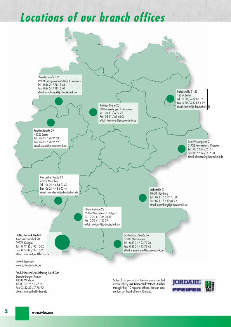
wwwh-baucom2
Markircher Straszlige 1468229 MannheimTel 06 21 4 84 03 40Fax 06 21 4 84 03 44eMail mannheimjp-bautechnikde
Houmllderlinstraszlige 2375446 Wiernsheim StuttgartTel 0 70 41 86 08 58Fax 0 70 41 22 39eMail stuttgartjp-bautechnikde
Fundlandstraszlige 2945326 EssenTel 02 01 28 96 60Fax 02 01 28 96 620eMail essenjp-bautechnikde
Oeseder Straszlige 11549124 Georgsmarienhuumltte b OsnabruumlckTel 0 54 01 78 15 44Fax 0 54 01 78 15 40eMail osnabrueckjp-bautechnikde
Stettiner Straszlige 2030916 Isernhagen HannoverTel 05 11 6 17 79Fax 05 11 61 46 04eMail hannoverjp-bautechnikde
Nobelstraszlige 51-5512057 BerlinTel 0 30 6 82 83-02Fax 0 30 6 82 83-4 99eMail berlinjp-bautechnikde
Zum Wiesengrund 201723 Kesselsdorf DresdenTel 03 52 04 2 15 11Fax 03 52 04 2 15 18eMail dresdenjp-bautechnikde
Lechstraszlige 2190451 NuumlrnbergTel 09 11 6 42 78 08Fax 09 11 6 42 84 72eMail nuernbergjp-bautechnikde
Dr-Karl-Lenz-Straszlige 6687700 MemmingenTel 0 83 31 93 72 20Fax 0 83 31 93 73 42eMail memmingenjp-bautechnikde
H-BAU Technik GmbHAm Guumlterbahnhof 2079771 KlettgauTel 0 77 42 92 15-20Fax 0 77 42 92 15-90eMail infoklettgauh-baude
wwwh-baucomwwwjp-bautechnikde
Produktion und Auslieferung Nord-OstBrandenburger Straszlige14641 WachowTel 03 32 39 7 75-20Fax 03 32 39 7 75-90eMail infoberlinh-baude
Sales of our products in Germany are handledexclusively by JampP Bautechnik Vetriebs-GmbHthrough their 10 regional offices You can alsocontact our head office in Klettgau
Locations of our branch offices
for superior solutions
1
ISOPROreg
Balcony insulation elements
Contents
ISOPROreg Thermal insulation elementsGeneral Technical principles 2
Building physics ndash Heat insulation 3-7Building physics ndash Fire protection 8Exposition class 9
Isoproreg Overview of types 10-11Order codes and installation positions 12
Type IP-IPT Examples 13Construction and dimensions 14-15Dimensioning table 16-17On-site reinforcement and installation instructions 18-19Special types 20-21Deflection and height offset 22-23Expansion joint spacing 24Two-part elements 25-26
Type IPT-Corner Construction and dimensionsDimensioning table 27-28On-site reinforcement 29
Type IPQ-IPQS Examples of transverse force elements 31Construction and dimensionsDimensioning table 32-35On-site reinforcement 33
Type IPQQ-IPQQS Construction and dimensionsDimensioning table 36-39On-site reinforcement 37
Type IPTD Construction and dimensions 40On-site reinforcement 41Dimensioning table 42-43
Type IPQZ Construction and dimensionsDimensioning table 44On-site reinforcement 45
Type IPH Construction and dimensions 46On-site reinforcement 47
Type IPA Construction and dimensional values 48On-site reinforcement and installation instructions 49
Type IPF Construction and dimensional values 50On-site reinforcement and installation instructions 51
Type IPO Construction and dimensional values 52On-site reinforcement and installation instructions 53
Type IPS Construction and dimensional values 54On-site reinforcement and installation instructions 55
Type IPW Construction and dimensional values 56On-site reinforcement and installation instructions 57
Approval 58Tender 59
ISOPROreg - Insulation at the highest level
The constructionISOPROreg is a thermally insulatingsupporting connection element be-tween concrete construction compo-nents Its excellent thermal insulationproperties provide a reliable solutionto the problems of building physicsat the interface between externaland internal construction elementsISOPROreg consists of an insulationbody together with a static rodframework which ensures effectivetransfer of static forces
Insulation materialThe insulation body is 80 mm thickThe material used is EPS (WLG 035)
FrameworkThe integral reinforcement rods aremade from BST 500 in the area ofthe insulation and up to 10 cm to theside from BST 500 NR Elementsmade from high-performance spe-cialty concrete are predominantlyused in the compression zone
This eliminates any potential corro-sion problems and provides optimalabsorption of transverse forces andbending moments
QualityThe consistently high quality stan-dard of ISOPROreg is maintained bycontinual in-house and third-partymonitoring
Applications FeaturesThe compact and easy-to-handleISOPROreg elements are deliveredready for rapid problem-free instal-lation
SafetyThe arrow indicator is always at thetop and points in the direction of thebalcony slab to be connected The el-ement identification together withinformation on the concrete coveringand height of the element is also in-dicated on each elementThe ISOPROreg elements are simplyconnected by overlapping with theon-site reinforcement (in accordancewith structural specifications)
Projecting balcony with ISOPROreg type IP
Thermod
aumlmm
Thermod
aumlmm
Balkon
seite
Balkon
seite
Projecting balcony with ISOPROreg type IPT
Projecting balcony with ISOPROreg type IPQ
ISOPROreg
Technical principles
wwwh-baucom2
Thermal bridgeIn the construction of buildings un-considered thermal bridges are a hid-den risk Thermal bridges are definedas locations in parts of a building inwhich heat transfer to the outside oc-curs more quickly than in other partsof the building
There is a difference between geo-metrical thermal bridges in which forthe heat dissipation from the internalsurface there is an adjacent largerexternal surface (eg external cornersof the building) and constructed ther-mal bridges which create thermalbridges by the use of fixtures or ma-terials with high heat conductivity orlack of thermal insulation One ex-ample of constructive thermal bridgesis reinforced concrete elements whichpenetrate external walls At low out-side temperatures this increased heatflow leads to lower temperatures atthe surface of the room wall Prob-lems of decreasing temperatures re-sult from surface contact with the airin the room and its water retention ca-pacity
Air humidityAir humidity (also air moisture) is de-fined as the proportion of watervapour mixed with gas (in this case inthe room) The best known measureof humidity is the relative humiditygiven as a percentage which relatesto the proportion ofwater vapour content in the air to themaximum possible content at anytime At lower temperatures the waterretention capacity is lower than athigher temperatures so that onecubic metre of air at 10ordmC can absorb941 g of water
The same volume of air at 30ordmC canabsorb up to 3038 g of water This isknown as saturation concentration
Due to fluctuating temperatures forthe same water concentration the rel-ative humidity in the room alsochanges Air which is being cooledat the surface close to the thermalbridge produces an increase in rela-tive humidity until it reaches satura-tion concentration
Dew point temperatureThe temperature at which the watervolume in the air is sufficient to causesaturation (relative humidity of 100)is known as the dew point tempera-ture since a further decrease in tem-perature will cause excess humidity tobe released from the air as conden-sate This condensate attaches itself tothe surface of the wall
Therefore the higher the temperatureand relative humidity levels in the
room are the higher is the condensa-tion point temperature and with it theincreased risk of water condensationon the colder parts of the building sur-faces The assumed room climate is20ordmC and 50 relative humidity Forthese conditions the dew point tem-perature is 93ordmC
The minimum heat insulationThe hazard threat comes not onlyfrom humidity-related effects on con-struction elements and the associateddamage to the building but moreimportantly also from the health haz-ard due to mildew formation in theseareas The formation of mildew doesnot only start at the point when watercondensation occurs but already atthe point when the surface tempera-ture at the wall produces 80 relativeair humidity For normal climatic con-ditions in a room the non-critical sur-face temperature is 126ordmC Whenthis surface temperature is reachedthere is no further hazard risk
airtem
perature
22degC
airtem
perature
20degC
air temp
erature
18degC
dew
pointtem
perature
[degC]
Relative humidity []
40 45 50 55 60 65 70 75 80 85 90
20
18
16
14
12
10
8
6
Dependence of the dew point temperature on relative humidity and air temperature
93
126
No risk of mildew formation from126ordmC(DIN 4108-2 2001-03)
ISOPROreg
Building physics ndash Heat insulationfor superior solutions
ISOPROreg - Insulation at the highest level3
no risk
Isopro is in conformance with DIN 4108 supplementary sheet 2in accordance with approval Z-157-244
1) cf thermal protection technical asses-sment from the Ingenieurgesellschaftfuumlr technische Computeranwendun-gen Falkenburger und Partner72793 Pfullingen
2) cf General technical approval fromthe German Institute for ConstructionZ-157-185 page 4 point 215
3) cf Test report from the Research Insti-tute for Heat Insulation (FIW) MunichReport No B1-1999 and B3 0205
Balcony thermal bridges ndash Proof complying with EnEV (Energy Saving Ordinance)
According to DIN V 4108-6 [13] two processes are available ndash a blanket consideration or a detailed proof
Process 1 blanket specific thermal bridge addition ∆ UWBThe specific transmitted heat loss is given by
HT = Σ Ui middot Ai middot Fxi + ∆ UWB middot A
with HT [WK] specific transmitted heat lossUi [Wmsup2K] heat transfer coefficientAi [msup2] surface area of componentFxi [-] temperature correction factor for components∆ UWB [Wmsup2K] blanket specific thermal bridge additionA [msup2] heat-exchanging surface envelope
Process 1a Without further proof∆ UWB = 010 [Wmsup2K]
Process 1b All thermal bridges in the building comply with the planning and execution examples given in DIN4108 supplementary sheet 2 2004-1 and are therefore in compliance with the supplementarysheet Balcony insulation elements are in compliance with the supplementary sheet (constructiondetail Figure 71) This process is used in practice
∆ UWB =005 [Wmsup2K]
Process 2 For the detailed proof process the thermal bridge effects are precisely measured The prerequisitefor this process is that all of the connection details are known for the length-dependent thermalbridge loss coefficientThe specific transmitted heat loss is given by
HT = Σ Ui middot Ai middot Fxi + Σ Ψi middot li middot Fxi
Ψ [WmK] length-dependent thermal bridge loss coefficientl [m] connection length of the related construction component
Isoproreg 2) 3) Virtual 1)
+20degC-10degC +20degC-10degC
+17degC +18degC
wwwh-baucom
ISOPROreg
Building physics ndash Heat insulation
4
To process 2 The length-dependent thermal bridge loss coefficient Ψ [WmK] can be found in thetable The average equivalent heat conductivity λeq is a reference value for identicalwall construction Tolerances of +- 10 can be expected These values will lead toincorrect results if the wall construction is non-compliant
according to DIN 4108-2 2003-07 and DIN 4108 supp sheet 2 2004-0101 for external heat transferresistance Rse = 004 msup2 sdot KW and internal Rsi = 025 msup2 sdot KW for fRsi and external Rse = 004 msup2 sdot KW andinternal Rsi = 013 msup2 sdot KW for Ψ value Outside temperatur ϑa = -5degC internal
H-BauTechnology
External insulationAverage equivalentheat conductivity
Thermal bridge losscoefficient Ψ refer-red to external di-mensions
Temperature factor fRsiMinimum surface tempera-ture ϑmin
TypeThickness[mm]
Heat conduc-tion group[W(m sdot K)]
Thermal insulation bonding system
λeq[W(m sdot K)]
Ψ[W(m sdot K)]
fRsi[ - ]
ϑmin[ degC ]
IP 107 cv3080 004 018 020 086 164
140 004 018 023 088 170
IP 1210 cv30
80 004 035 035 085 157
140 004 035 037 086 164
250 004 035 037 088 169
IPT 1210cv 30
140 004 018 023 088 171
according to DIN 4108-4 1998-10 for heat transfer resistance external Rse = 004 msup2 sdot KW andinternal Rsi = 013 msup2 sdot KW fuumlr fRsi and ψ value Outside temperature ϑa = -5degC
TypThickness[mm]
Heat conduc-tion group[W(m sdot K)]
Thermal insulation bonding system
λeq[W(m sdot K)]
Ψ[W(m sdot K)]
fRsi[ - ]
ϑmin[ degC ]
according toapprovalZ 157-185
80 004 041 090 170 degC
For data on dimensions thermal conductivity and boundary conditions see FIW Test Report B3-0205 For data on dimensions thermal conductivity and boundary conditions see FIW Test Report B1-1999rdquo stainless steel compression rodBalcony slab thickness d = 180 mm
ISOPROreg - Insulation at the highest level
ISOPROreg
Building physics ndash Heat insulationfor superior solutions
5
taken from audit by FIW Munich
Minimum heat insulation DIN 4108-2Considerably lower surface temperatures can occur in the vicinity of thermal bridges than in more controlled areas In order to exclude the possi-bility of mildew formation in living space with normal use it is necessary with the exception of windows and window frames to maintain a tem-perature factor of fRsi ge 07 at unfavourable locations No calculated proof is required
for connections constructed in accordance with DIN 4108 supp sheet 2for external corner elements with the same construction whose individual components satisfy the minimum heat insulationfor common connection materials such as nails screws and wire anchors it is not necessary to prove thermal bridge effects
Table 5 Determination of the specific thermal bridge addition ∆∆ UWB for an apartment house (Figure 5 Timber Construction Handbook)
Type Description l [m] ΨΨ [WmK] FtW [-] F xΨΨ x l [WK]
BA1 internal cellar wall on floor slab 1362 -0086 055 -0644BA2 internal cellar wall on floor slab 100 -0178 055 -0098BA3 cellar door soffit 420 0035 055 0080BA4 cellar door lintel 100 0043 055 0024BA5 cellar wall with ground contact on floor slab 330 0235 060 0465
BA6 unheated cellar internal wall to external cellar wall 1064 -0229 060 -1460
BA7 internal outer corner of cellar -0229 055BA8 unheated cellar internal wall to internal wallBA9 cellar internal wall to cellar ceiling unheated 900 0002 055 1100
BA10 cellar internal wall to cellar ceilingunheatedheated 332 0361 055 0658
BA11 cellar internal wall to cellar ceilingunheatedheated without internal wall 200 0256 055 0282
BA12 stair well 1130 0093 055 0580BA13 basement of staircaseBA14 basement 5522 -0034 100 -1885BA15 outside corner 3512 -0078 100 2734BA16 window soffit 4050 0029 100 1174BA17 window parapet 2425 0022 100 0540BA18 window lintel 2425 0034 100 0828BA19 house doorterrace door threshold 280 -11186 100 -0521BA20 house door soffit 250 0043 100 0106BA21 house door lintel 280 0137 100 0382BA22 internal wall on cellar wall and cellar ceiling 4291 0035 055 0816BA23 internal wall on cellar ceiling 1715 0034 055 0323BA24 internal wall on external wall 7902 0007 100 0548BA25 embedding of floors and ceilings 11043 0015 100 1639BA26 ceilings on the storey to unheated attic 2484 -0063 100 -1560BA27 internal wall to unheated attic 7615 0015 100 1137BA28 termination of eaves
BA29 termination of eaves on the storey level tounheated attic 3328 -0079 080 -2091
BA30 exposed area connectionsBA31 ridge connectionBA32 internal wall on inclined roofBA33 window frame on storey ceiling 660 0210 100 1383
Specific thermal bridge addition ∆ UWB= Σ (F middotΨ middot l)AW(msup2K)=000with A (heat-exchanging surface envelope) A=966msup2 total = 0040
Addition balcony with Isopro IP1210 500 0370 100 185Specific thermal bridge addition ∆ UWB= Σ (F middotΨ middot l)AW(msup2K) = 000with A (heat-exchanging surface envelope) A=966msup2 + 10msup2 balcony area total = 1890
Result The balcony slab does not change the specific thermal bridge addition ∆∆ UWBExtract from Timber Construction Handbook Series 3 part 2 2nd edition Dec 2000
wwwh-baucom
ISOPROreg
Building physics ndash Heat insulation
6
Variants of balcony thermal bridge calculations ndash detailed proof
Example taken from the Timber Construction HandbookIsoproreg Type IP 1210 Ψ = 037 WmK length of the balcony slab 50 m AB = 10 msup2 detached house heat-ex-changing surface envelope 43471 msup2 + 10 msup2∆UWB =(F middot Ψ middot l )A = (10 middot 037 middot 5)43471 = 000416alt Isoproreg Type IPT 1210 Ψ = 023 WmK length of the balcony slab 50 m AB = 10 msup2 detached house heat-exchanging surface envelope 43471 msup2 + 10 msup2∆UWB =(F middot Ψ middot l )A = (10 middot 023 middot 5)43471 = 000286
For an average heat penetration value of the external envelope of U = 021 Wmsup2K the result is
with Isoproreg IP 1210 an addition for ∆UWB = 20 with Isoproreg IPT 1210 an addition for ∆UWB = 14
this gives a difference between the systems of 06 which is irrelevantThe deviations of the thermal transfer values for various elements are not relevant since the thermo-technical impro-vements referred to the total envelope are minimal
Source Timber Construction Handbook Series 3 Part 2 2nd edition Printed 2000
Fig 71
Extract from DIN 4108 supp sheet 2
NoteThermally-isolated constructions must be used
Balcony insulation elements arethermo-technically equivalent ifthey comply with Fig 71 or DIN 4108 supp sheet 2 No additional proof is required
system
comp
arison
IP 1210 ∆UW
B = 0
6
DIN 4108 supp sheet 2 Fig 71 regulates balcony thermal bridges
Isoproreg conforms to supplemental sheet 2 of DIN 4108 in accordance with the Approval As a result of the confirma-tion of conformity for balcony thermal bridges no further proof is required
More precise calculations are possible using the thermal bridge loss coefficient Ψ These processes are very time con-suming If not all thermal bridges in a building are recorded according to DIN 4108 supplemental sheet 2 this proofis not admissible For this reason the EnEV (Energy Saving Ordinance) provides the possibility of blanket thermal bridgeadditions
ISOPROreg - Insulation at the highest level
for superior solutions
7
ISOPROreg
Building physics ndash Heat insulation
Fire-resistance class F 30
All ISOPROreg elements are categorised as fire protection class F 30 The requirements to be met for the complete con-struction are illustrated in the following diagrams
Fire-resistance class F 90
All ISOPROreg elements are also supplied to fire-resistance class F90 meeting the technical requirements for fire protectionof balconies etc
The designation F90 is added to the element identification eg ISOPROreg IP107 cv 30 F90
The ISOPROreg elements are fitted with fire protection plates attached to the top-side and the under-side The construction can be seen in the sketch of the system below
It is self-evident that to meet the requirements of the fire-resistance class F90 all other adjacent construction elementsmust also satisfy these requirements For constructions with selected-point connections it is necessary to ensure that theintermediate insulation also meets the fire-resistance requirements
100
158
F90 fire protection slab
F90 fire protection slabdetail 1
detail 1
mineral-based plaster
screeding plastering
ISOPRO element
A1 materialnon-flammable
ISOPRO element
mineral-based plaster mineral-based plaster
screeding plastering
100
158
F90 fire protection slab
F90 fire protection slabdetail 1
detail 1
mineral-based plaster
screeding plastering
ISOPRO element
A1 materialnon-flammable
ISOPRO element
mineral-based plaster mineral-based plaster
screeding plastering
wwwh-baucom8
ISOPROreg
Building physics - Fire protection DIN 4109
F30 ndash wall area construction F30 ndash door area construction
Table for concrete covering
This table for concrete covering isextracted from Tables 3 + 4 in DIN1045-1 63The recommendations for externalbalconies are
- in-situ concrete balconies prefa-bricated balconies and filigreeslabs with in-situ concrete cover-ing and permanent sealing onthe top surface
middot concrete class C 2530middot exposition class XC4 with cv 30
- in-situ concrete balconies prefa-bricated balconies and filigreeslabs with in-situ concrete cover-ing without permanent sealing
middot concrete class C 2530middot exposition class XC4 with cv 35
DIN 1045-1 Concrete covering
For constructions in accordance with DIN 1045-1 the most binding requirement is the issue of concrete covering(exposition class)
The following concrete coverings (cv) are frequently encountered
cv = 30mm cv = 35mm cv = 40mm cv = 50mm (second layer for cv = 30mm and cv = 35mm)
Example IP 1210 cv 30 h = 180 mm
Always include the element height
Exposition classes and concrete covering
Reinforcement corrosion Minimum concretestrength class
Depth of concretecovering cnom
Red depth of con-crete covering cv
XC3 high humidity outsideconstruction elementsdamp rooms
C 2025 cnom = 35 mm cv = 30 mm
XC4 alternating wet and dryoutside construction ele-ments exposed to rain
C 2530 cnom = 40 mm cv = 35 mm
XD1 high humidity area ofspray water from roadsurface
C 3037 cnom = 55 mm cv = 50 mm
XS1 salt-laden air outsideconstruction elementsnear coasts
C 3037 cnom = 55 mm cv = 50 mm
Concrete attack Minimum concretestrength class
Concrete covering
XF1 high water saturationwith no condensationsource outside con-struction elements
C 2530cv = degree of
reinforcement corrosion
cv = a reduction of 5mm according to DIN 1045-1 63 is taken into account
ISOPROreg - Insulation at the highest level
for superior solutionsISOPROreg
Exposition classes
9
wwwh-baucom10
ISOPROreg Type IPfor freely-protruding balcony slabs The element transfers negative bendingmoments and positive transverse forces
ISOPROreg Type IPTfor freely-protruding balcony slabs The element transfers negative bendingmoments and positive transverse forces
ISOPROreg Type IPT - Cornerfor freely-protruding external-corner balconies The element transfers ne-gative bending moments and positive transverse forces
ISOPROreg Type IPQfor joint-supported slabs (eg balconies and loggias on supports) The element transfers positive transverse forces
ISOPROreg Type IPQSfor joint-supported slabs with selected-point force transferThe element transfers positive transverse forces
ISOPROreg Type IPQQfor joint-supported slabs The element transfers positive and negative transverse forces
ISOPROreg Type IPQQSfor joint-supported slabs with selected-point force transfer The element transfers positive and negative transverse forces
ISOPROreg
Overview of types and applications
ISOPROreg - Insulation at the highest level
for superior solutions
11
ISOPROreg Typ IPTDfor balcony slabs which enter the floored area The element transfers po-sitive and negative bending moments and transverse forces
ISOPROreg Type IPAfor connection of fascias at storey floor level The element is attached at selected points
ISOPROreg Type IPFfor connection of protruding parapets at storey floor levelThe element is attached at selected points
ISOPROreg Type IPOfor connection of reinforced concrete consoles at storey floor level The element is attached at selected points
ISOPROreg Type IPSfor connection of wall consoles and cantilever beams The element transfers positive and negative transverse forces
ISOPROreg Type IPWFor connection of full-height wall plates The element transfers bending moments and transverse forces in both thevertical and horizontal direction
ISOPROreg
Overview of types and applications
Example of order code using element structural dataBalcony slab thickness h = 180 mmConcrete covering cv = 35 mm
mEd = 316 kNmmvEd = 514 kNm
Fire protection requirement F90
IP 1210 CV35 Q10 F90 h180
Type
load b
earing capacity
Concrete covering
supp transverse force
Fire protection F90
height of elem
ent
For types IPQ and IPQS no additional identification for theconcrete covering cv is required
Installation locations for ISOPROreg balcony insulation elements
ISOPROreg in single-skin brickwork ISOPROreg in single-skin brickwork with Thermal Insulation Bonding System
ISOPROreg in double-skin brickwork ISOPROreg in double-skin brickwork with rear ventilation
Order codes for ISOPROreg balcony insulation elements
variant lll HV lArrlArr ceiling offset upwardsvariant lll UV lArrlArr ceiling offset downwards
Additional identification for special element type IP
downward curve in the wall rArrrArr variant lupward curve in the wall rArrrArr variant ll
Sample order IP 127 varl CV35 h200
wwwh-baucom12
ISOPROreg
Order Codes and Installation Locations
IP IPT IP IPT
IP I
PT 2nd p
ositio
nIP IPT 2nd position
IP IPT IP IPT
IP IPT IPT Corner
IPT
Cor
ner
IP
IPT
IP IPT IP orIPT 1st position
IP
IPT
2nd
posi
tion
IP orIPT 1st position
Freely-protruding balcony
Side-separated internal corner balcony Internal-corner balcony
Internal-corner balconyloggia overlying on 3 sidespartially projecting
External corner balcony
ISOPROreg - Insulation at the highest level
for superior solutions
13
ISOPROreg Type IP IPTExamples
balcony side slab side
balcony side slab side
Dimensions Type IP [length in mm]
TypeTension rod Transverse force rod Supplemental transverse force
ZL QL Q8L Q10L Q12LIP 88 560 297 497 - -IP 107 690 297 497 - -IP 108 560 337 497 617 742IP 127 690 337 497 617 742IP 128 690 337 497 617 742IP 129 690 337 497 617 742IP 1210 690 337 497 617 742
Top view
section IP
section IP - X
Expansion joint spacing for ISOPROreg Type IP can be found on page 24
Configuration of the elements
Type Length of element [mm] Tension rods Transverse force rodstandard X-variation
Compression blocks
IP 88 1000 8 Oslash 8 4 Oslash 6 8 Oslash 6 4IP 107 1000 6 Oslash 8 + 2 Oslash10 4 Oslash 6 8 Oslash 6 4IP 108 1000 10 Oslash 8 4 Oslash 8 8 Oslash 8 4IP 127 1000 9 Oslash 10 4 Oslash 8 8 Oslash 8 6IP 128 1000 10 Oslash 10 4 Oslash 8 8 Oslash 8 6IP 129 1000 11 Oslash 10 4 Oslash 8 8 Oslash 8 7IP 1210 1000 12 Oslash 10 4 Oslash 8 8 Oslash 8 8
wwwh-baucom
ISOPROreg Type IPConstruction and dimensions
14
Type certificateNr 0517
Buildings InspectorateapprovalNr Z-157-244
1000
20
20
balcony slab
balcony slab
Dimensions Type IPT [length in mm]
TypeTension rod Transverse force rod Compression rods Supplemental transverse force
ZL QL DL Q10L Q12L Q14LIPT 1211 820 382 165 472 572 662IPT 1212 820 382 165 472 572 662IPT 1412 820 382 165 472 572 662IPT 1414 960 382 200 472 572 662
Top view
section IPT
Expansion joint spacing for ISOPROreg Type IPT can be found on page 24
Configuration of the elements
Type Length of element [mm] Tension rods Transverse force rodstandard X-variation
Compression rods
IPT 1211 500 + 500 6 Oslash 10 + 4 Oslash12 4 Oslash 8 8 Oslash 8 6x2 Oslash 10 + 4x2 Oslash12IPT 1212 500 + 500 10 Oslash 12 4 Oslash 8 8 Oslash 8 10x2 Oslash 12IPT 1412 500 + 500 12 Oslash 12 4 Oslash 8 8 Oslash 8 10x2 Oslash 14IPT 1414 500 + 500 10 Oslash 14 4 Oslash 8 8 Oslash 8 10x2 Oslash 14
ISOPROreg - Insulation at the highest level
for superior solutions
15
ISOPROreg Type IPTConstruction and dimensions
section IPT - X
Type certificateNr 0518
Buildings InspectorateapprovalNr Z-157-243
Types with increased transverse-force load capacity
Type IP 88Q
IP 107Q
IP 108Q
IP 127Q
IP 128Q
Rated values for transverse-force loading vRd [kNm]
Q8 (4Oslash8) h ge 160mm 618Q10 (4Oslash10) h ge 170mm 966Q12 (4Oslash12) h ge 180mm 1391
Plate thickness [cm] with re-ference to cv [mm] Rated values for moment loading mRd [kNmm]
30 35 40 45 50 IP 88 IP 107 IP 108 IP 127 IP 128
- - - - 16 103 124 137 192 203- - - 16 - 110 132 145 204 216- - 16 - 17 116 140 154 216 229- 16 - 17 - 123 148 163 228 24216 - 17 - 18 129 156 172 240 255- 17 - 18 - 136 164 181 252 26817 - 18 - 19 142 171 189 264 281- 18 - 19 - 148 179 198 276 29418 - 19 - 20 154 187 206 289 306- 19 - 20 - 161 195 215 301 31919 - 20 - 21 167 203 223 313 332- 20 - 21 - 174 211 232 325 34520 - 21 - 22 180 219 240 337 358- 21 - 22 - 187 227 249 349 37121 - 22 - 23 193 234 257 361 384- 22 - 23 - 200 242 266 373 39722 - 23 - 24 206 250 275 386 409- 23 - 24 - 213 258 284 398 42223 - 24 - 25 219 266 292 410 435- 24 - 25 - 226 274 301 422 44824 - 25 - - 232 282 309 434 461- 25 - - - 239 289 318 446 47425 - - - - 245 297 326 458 486
Rated values for transverse-force loading vRd [kNm]h = 160 - 250 [mm] 275 275 415 415 415
Rated values for transverse-force loading vRd [kNm]
Type IP 88 IP 107 IP 108 IP 127 IP 128X plusmn275 plusmn415
Q8X + 618 - 488Q10X + 966 - 696Q12X + 1391 - 696
wwwh-baucom
ISOPROreg
Dimensioning table for concrete gege C2025
16
Types with positive and negative transverse-force capacity
IP 129Q
IP 1210Q
IPT 1211Q
IPT 1212Q
IPT1412Q
IPT1414Q
Rated values for transverse-force loading vRd [kNm]
6189661391
Rated values for moment loading mRd [kNmm]
IP 129 IP 1210 IPT1211 IPT1212 IPT1412 IPT1414
234 255 283 319 368 439249 272 301 339 391 468264 288 319 360 415 497279 304 337 380 439 526293 320 356 401 463 555308 336 374 421 486 584323 352 392 442 510 613338 369 410 462 534 642353 385 428 482 558 671367 401 446 503 582 699382 417 464 523 606 728397 433 482 544 629 757412 449 501 564 653 786427 466 519 585 677 815441 482 537 605 701 844456 498 555 625 725 873471 514 573 646 749 902486 540 591 666 773 931501 566 609 687 796 960516 573 628 707 820 988530 579 646 728 844 1017545 595 664 748 868 1046560 611 682 769 892 1075
Rated values for transverse-force loading vRd [kNm]415 415 415 415 415 415
Rated values for transverse-force loading vRd [kNm]
IP 129 IP 1210 IPT 1211 IPT 1212 IPT 1412 IPT 1414plusmn415
+ 618 - 488+ 966 - 696+ 1391 - 696
ISOPROreg - Insulation at the highest level
for superior solutions
17
ISOPROreg
Dimensioning table for concrete gege C2025
balcony slab
Section A - A
AA
a
aa
b
c
b
c
c
c
b
b
tension rod ISOPRO
compression support ISOPROtransverse force bars ISOPRO
integral suspension reinforcement upper reinforcement of steel bars or mesh
lower reinforcement of steel bars or mesh
insert stirrup Oslash 8
d
d secondary reinforcement Oslash 8
concrete concrete
100
mesh support
floor balcony
1 Lay the lower reinforcement for the floor slab2 Install ISOPROreg IP and align The direction of alignment
(arrow symbol on top of element) must be followed3 Insert the edging (in accordance with DIN 1045-1) and
the upper floor reinforcement and bind together withthe ISOPROreg tension rods The ISOPROreg tension rodsand the support reinforcement are at the same level Ifrequired the binder on the tension rod level can be cutthrough
4 Lay the lower reinforcement and the edging for thebalcony slab in accordance with DIN 1045-1
5 Lay the balcony-side distribution rods one Oslash 8 top andbottom pos with insert stirrups pos separatedfrom the insulation body by approx 50 mm
6 Insert the upper floor reinforcement and bind to-gether with the ISOPROreg tension rods The ISOPROreg
tension rods and the support reinforcement are at thesame level
7 It is necessary when concreting to fill and pack uniformlyon both sides in order to prevent movement of the ISO-PROreg elements
ISOPROreg Type IP with on-site mesh supportThe mesh support replaces the suspension reinforce-ment It should be installed at a distance of le 100 mmfrom the insulation and raised up until it is immediatelybelow the tension reinforcement The diameter of thediagonals must be at least 5 mm The transverse forcerod can be positioned above or below the mesh sup-port
Since the contact pressure will be calculated as notgreater than fcd=085 middot fck γc no gap or edge ten-sioning reinforcement is required It is only necessaryto have edging on both sides of the insulation Thisshould be dimensioned for VRd
For indirect support of the ISOPROreg elements a suspensionreinforcement which is dimensioned for VRd is also re-quired on the floor side The bending reinforcement of thejoist must be according to structural calculations howeveras a minimum one Oslash 8 top and bottom is required
wwwh-baucom18
ISOPROreg Type IPOn-site reinforcement and installation instructions
balcony slab
upper reinforcement of steel bars or mesh
lower reinforcement of steel bars or mesh
insert stirrup Oslash 8A
Aa
b
c
a
c
b
section A - A
a
c
b
transverse force bars ISOPRO compression strut ISOPRO
integral suspension reinforcement tension rod ISOPRO
d
d
b
c
concrete concrete
secondary reinforcement Oslash 8
1 Lay the lower reinforcement for the floor slab2 Install ISOPROreg IPT and align The direction of alignment (arrow symbol on top of element) must be followed3 Insert the edging (in accordance with DIN 1045-1) and the upper floor reinforcement and bind together with the
ISOPROreg tension rods The ISOPROreg tension rods and the support reinforcement are at the same level If requiredthe binder on the tension rod level can be cut through
4 Lay the lower reinforcement and the edging for the balcony slab in accordance with DIN 1045-15 Lay the balcony-side distribution rods one Oslash 8 top and bottom pos with insert stirrups pos separated from
the insulation body by approx 50 mm6 Insert the upper floor reinforcement and bind together with the ISOPROreg tension rods The ISOPROreg tension rods
and the support reinforcement are at the same level7 It is necessary when concreting to fill and pack uniformly on both sides in order to prevent movement of the ISOPROreg
elements
For indirect support of the ISOPROreg elements a suspension reinforcement which is dimensioned for VRd is also requiredon the floor side The bending reinforcement of the joist must be according to structural calculations however as a mi-nimum one Oslash 8 top and bottom is required
Since the contact pressure will be calculated as not greater than fcd=085 middot fck γc no gap or edge tensioning rein-forcement is required It is only necessary to have edging on both sides of the insulation This should be dimensionedfor VRd
ISOPROreg - Insulation at the highest level
ISOPROreg Type IPTOn-site reinforcement and installation instructions
for superior solutions
19
ISOPROreg Type IPOn-site reinforcement and installation instructions
balcony
slab
wall
balcony
h lt
80
ab
c
a
b
c
aa
a
a
b
c
b
c
a
a
bb
a
c
c
ee
d
d
b
b
upper reinforcement of steel bars or mesh
lower reinforcement of steel bars or mesh
closed stirrup
inse
rt s
tirru
p
reinforcement
upper reinforcement of steel bars or mesh
lower reinforcement of steel bars or mesh
closed stirrup
upper reinforcement of steel bars or mesh
lower reinforcement of steel bars or mesh
clos
ed s
tirru
p
insert stirrup
parallel reinforcement
ain
sert
stir
rup
b
reinforcementb
wall
balcony wall
balcony
slab
balcony
slab
ndash If the height offset is less than 80 mm a standardelement can also be used
ndash In this case a stirrup reinforcement with an upper leglength gt ls is required to deflect the tensile force onthe floor side
ndash Dimensioning the stirrup reinforcement for the can-tilever effects and transverse forces from the balcony
slabndash For connection reinforcement on the balcony side see
page 1819ndash The necessary transverse reinforcement in the overlap
area must be proved in accordance with DIN 1045-1ndash Recommended joist width at least 200 mm
Connection to a ldquomarginallyrdquo height-offset floor slab
balcony
slab
wall
balcony
h lt
80
ab
c
a
b
c
a
a
a
a
b
c
b
c
a
a
bb
a
c
c
ee
d
d
b
b
upper reinforcement of steel bars or mesh
lower reinforcement of steel bars or mesh
closed stirrup
inse
rt s
tirru
p
reinforcement
upper reinforcement of steel bars or mesh
lower reinforcement of steel bars or mesh
closed stirrup
upper reinforcement of steel bars or mesh
lower reinforcement of steel bars or mesh
clos
ed s
tirru
p
insert stirrup
parallel reinforcement
ain
sert
stir
rup
b
reinforcementb
wall
balcony wall
balcony
slab
balcony
slab
ndash The ISOPROreg tension rods comply with the necessaryoverlap length ls given in DIN 1045-1
ndash For connection reinforcement on the balcony side seepage 1819
ndash The necessary transverse reinforcement in the overlaparea must be proved in accordance with DIN 1045-1
ndash The minimum wall thickness is dependent on the type
Connection to a vertical wall ndash connection downwards
balcony
slab
wall
balcony
h lt
80
ab
c
a
b
c
a
a
a
a
b
c
b
c
a
a
bb
a
c
c
ee
d
d
b
b
upper reinforcement of steel bars or mesh
lower reinforcement of steel bars or mesh
closed stirrup
inse
rt s
tirru
p
reinforcement
upper reinforcement of steel bars or mesh
lower reinforcement of steel bars or mesh
closed stirrup
upper reinforcement of steel bars or mesh
lower reinforcement of steel bars or mesh
clos
ed s
tirru
p
insert stirrup
parallel reinforcement
ain
sert
stir
rup
b
reinforcementb
wall
balcony wall
balcony
slab
balcony
slab
ndash The ISOPROreg tension rods comply with the necessaryoverlap length ls given in DIN 1045-1
ndash For connection reinforcement on the balcony side seepage 1819
ndash The necessary transverse reinforcement in the overlaparea must be proved in accordance with DIN 1045-1
ndash The minimum wall thickness is dependent on the type
Connection to a vertical wall ndash connection upwards
wwwh-baucom20
ISOPROreg
Special types Valid for type series IP and IPT (analogously)
balcony
slab
wall
balcony
h lt
80
ab
c
a
b
c
a
a
a
a
b
c
b
c
a
a
bb
a
c
c
ee
d
d
b
b
upper reinforcement of steel bars or mesh
lower reinforcement of steel bars or mesh
closed stirrup
inse
rt s
tirru
p
reinforcement
upper reinforcement of steel bars or mesh
lower reinforcement of steel bars or mesh
closed stirrup
upper reinforcement of steel bars or mesh
lower reinforcement of steel bars or mesh
clos
ed s
tirru
p
insert stirrup
parallel reinforcement
ain
sert
stir
rup
b
reinforcementb
wall
balcony wall
balcony
slab
balcony
slab
ndash dimensioning of the stirrup reinforcement for can-tilever effect and transverse force on the balcony slab
ndash the ISOPROreg tension rods comply with the DIN 1045-1 requirement for overlap length ls
ndash for on-site reinforcement see pages 1819
ndash the required transverse reinforcement in the overlapzone must be proven in compliance with DIN 1045-1
ndash recommended step-down width at least 220 mm
Connection to a floor slab with a step-up offset
balcony
slab
wall
balcony
h lt
80
ab
c
a
b
c
a
a
a
a
b
c
b
c
a
a
bb
a
c
c
ee
d
d
b
b
upper reinforcement of steel bars or mesh
lower reinforcement of steel bars or mesh
closed stirrup
inse
rt s
tirru
p
reinforcement
upper reinforcement of steel bars or mesh
lower reinforcement of steel bars or mesh
closed stirrup
upper reinforcement of steel bars or mesh
lower reinforcement of steel bars or mesh
clos
ed s
tirru
p
insert stirrup
parallel reinforcementa
inse
rt s
tirru
p
b
reinforcementb
wall
balcony wall
balcony
slab
balcony
slab
ndash dimensioning of the stirrup reinforcement for can-tilever effect and transverse force on the balcony slab
ndash the ISOPROreg tension rods comply with the DIN 1045-1 requirement for overlap length ls
ndash for on-site reinforcement see pages 1819
ndash the required transverse reinforcement in the overlapzone must be proven in compliance with DIN 1045-1
ndash constructive angle reinforcement pos 3ndash recommended step-down width at least 220 mm
Connection to a floor slab with step-down offset
ISOPROreg - Insulation at the highest level
for superior solutions
21
ISOPROreg
Special types Valid for type series IP and IPT (analogously)
After stripping freely-protruding concrete slabs experience a lowering of the slab edge This displacement is a com-bination of the deformation of the balcony insulation elements used and the bending of the slab itself These two de-formations are superimposed and compensated by raising the formworkThe calculations shown below give the required formwork height offset at the end of the cantilever which results fromthe ISOPROreg elements at 100 loading For the total height offset the slab deformation should be added in accor-dance with DIN 1045-1 The total height offset defined in the construction plans from the structural design engineershould take into account the planned direction of the drainage when rounding off the results
wwwh-baucom22
ISOPROreg
Deflection and height offset
Element height h [mm] IP 88IP 107IP 108
IP 127IP 128IP 129
IP 1210
IPT 1211IPT 1212IPT 1412
IPT 1414Concrete covering cv
30 35 40 45 50160 051 059 092 106
160 048 056 087 100160 170 045 053 082 094
160 170 043 050 077 089160 170 180 041 047 073 084
170 180 039 045 070 080170 180 190 037 043 067 079
180 190 035 041 064 073180 190 200 034 039 061 069
190 200 033 038 059 067190 200 210 031 036 056 064
200 210 030 035 054 062200 210 220 029 034 052 059
210 220 028 033 050 057210 220 230 027 031 049 055
220 230 026 030 047 053220 230 240 026 029 046 052
230 240 025 029 044 050230 240 250 024 028 043 049
240 250 023 027 042 047240 250 023 026 040 046
250 022 025 039 045250 021 025 038 043
Offset height of the balcony slab
ISOPROreg - Insulation at the highest level
for superior solutionsISOPROreg
Deflection and height offset
Example for defining the balcony slab height offset
mEd bending moment used to determine the height offset resulting from the ISOPROreg elementThe definitive load combination is decided by the structural engineer
mRd design moment of the ISOPROreg element taken from the dimensioning table on pages 16 and 17lk Cantilever length in [m]
ExampleCantilever length lk = 180 mSlab thickness h = 180 mmIntrinsic weight (slab and covering) g = 60 kNm2
Edge load (parapet) F = 15 kNmLive load p = 40 kNm2
Concrete covering cv = 30 mm
Design calculationsmEd= (g + p) x lk2 2 + F x lk = (60 middot 135 + 40 middot 15) middot 182 2 + 15 middot 18 middot 135 = 265 kNmmvEd = (g + p) x lk + F = (60 middot 135 + 40 middot 15) middot 18 + 15 middot 135 = 274 kNm
Selected ISOPROreg IP 127 cv 30 h = 180 mm mRd = 289 kNmm vRd = 415 kNm
Selected load combination for determination of the height offset resulting from the ISOPROreg element mEd= (g + p3) middot lk22 + F middot lk= (60 middot 135 + 403 middot 15) middot 182 2 + 15 middot 18 middot 135 =200 kNmm
uuml = 041 middot (265 289) middot 180 middot 10 = 67 mm
23
uuml [mm] = value from table middot (mEdmRd) middot lk [m] middot 10
wwwh-baucom24
The external concrete components must have expansion joints at right angles to the insulation layer in order to limitthe stress caused by changes in temperature The spacing of the joints e is given in the following table
balcony
ISOPRO ISOPRO
expansion joint
balcony
e 2
e 2
ISOPRO Type IPT Corner
expansion joint
seperation ofexpansion joints e
seperation ofexpansion joints e
expansion jointExpansion joint spacing for ISOPROreg Types IP und IPT
Rod diameter [mm] le 10 12 14 16 20
Joint spacing e [m] 130 113 101 92 80
balcony
ISOPRO ISOPRO
expansion joint
balcony
e 2
e 2
ISOPRO Type IPT Corner
expansion joint
seperation ofexpansion joints e
seperation ofexpansion joints e
expansion joint
expansion joint dowellingeg HED-S + plastic sleeves
ISOPROreg
Expansion joint spacing
For corner constructions the maximum rod leg length is e2
ISOPROreg - Insulation at the highest level
for superior solutions
25
a a
b
c
b
c
sup3100
In pre-cast units
Arrange the lower reinforcement layer including themesh support as per structural design Distance to in-sulation joint le 100 mm (applies to IP only)
Install lower section The last transverse rod in themesh must be placed as close as possible to the insula-tion observing the required concrete covering
For IP the transverse force rod can be under or on topof the mesh The mesh support should be lifted until itis underneath the tension reinforcement
Concrete the slab element
Locate and fix the associated upper section andwhere required intermediate section
Type IP is supplied with suspension reinforcement asstandard
On-site
Lay the necessary on-site reinforcement on the floorside
Lay the slab element on the pre-prepared timberbeams
Lay the necessary on-site reinforcement on the bal-cony side
Attach the associated upper section and where re-quired intermediate section Bind the tension strutto the on-site reinforcement
h = 210 to 250 mm
Important note fit additional insertion stirrups Oslash 620 or stirrup meshQ188A on the balcony side
In type IP pre-cast units In type IPT pre-cast units
a a
b
c
b
c
sup3100
Type IP on-site Type IPT on-site
Important noteThe type identification for lower and upper sections must match (see also colour identification) The direction of in-stallation (on the balcony side) is mandatory
ISOPROreg
Two-part elements
wwwh-baucom26
upper section
centre section
lower section
upper section
centre section
lower section
balcony balconyslab slab
Type IP Type IPT
Construction
All ISOPROreg elements of types IP and IPT can be supplied as two-part elements
General notes
ndash The permitted resultant stresses can be found in thetables on pages 16 and 17 of this technical information
ndash Intermediate sections can be supplied for height offsetcompensation in 20 and 40 mm thicknesses
ndash Type IP If the mesh supports are placed with a spacingof le 100 mm from the insulation joint no additionalsuspension reinforcement is required Instead asuspension reinforcement dimensioned for VRd shouldbe located along the insulation joints
ndash For information regarding the required formwork height off-set and the maximum spacing of expansion joints refer topages 22 23 and 24
ndash The adhesive labels (type designation) for the upper andlower sections must be identical Follow the instructions forthe balcony side and the floor side
The following elements also have an addi-tional colour coding
ISOPROreg Type Colour code
IP 107 greenIP 127 blueIP 128 yellowIP 1210 white
The continuity of the colour coding throughthe elements ensures correct matching everytime even for short sections
ISOPROreg
Two-part elements
ISOPROreg - Insulation at the highest level
for superior solutions
27
balcony sidebalcony side
section 1st position
section 2nd position
slab balcony
1st position
2nd
posi
tion
cv
cvslab balcony
slab balcony
section 1st position
section 2nd position
1st position
2nd
posi
tion
slab balcony
IPT 127 Corner 820mmIPT 1210 Corner 960mm
IPT 127 Corner 820mmIPT 1210 Corner 960mm
IPT
127
Cor
ner
820m
mIP
T 12
10
Cor
ner
960m
mIP
T 12
7 C
orne
r82
0mm
IPT
121
0 C
orne
r96
0mm
General notes
Area of application for type IPT-Corner from slab thickness h le 180 mmOn-site reinforcement using overlap joints in accordance with DIN 1045-12001-07 Section 126Please refer to the information regarding on-site reinforcement on page 29Special elements for h = 160 mm are possibleBecause of the compression level a minimum spacing of the floor-side filigree slabs from the insulation body of185 mm is required for the ISOPROreg IPT-Corner elements
Type Length of element [m] Tension rods Compression level Transverse force rods
IPT 107-Corner 050 + 050 5 Oslash 10 + 5 Oslash 10 2 x 4 compression block 2 Oslash 10 + 2 Oslash 10
IPT 127-Corner 062 + 062 6 Oslash 12 + 6 Oslash 12 12 Oslash 14 + 12 Oslash 14 3 Oslash 10 + 3 Oslash 10
IPT 1210-Corner 062 + 062 6 Oslash 14 + 6 Oslash 14 14 Oslash 14 + 14 Oslash 14 3 Oslash 12 + 3 Oslash 12
Configuration of the elements
IPT 107-Corner
ISOPROreg Type IPT EckConstruction and dimensions
wwwh-baucom28
Plate thickness [mm] referred to cv [mm] Dimensional values for acceptable load moments MRd [kNm]
30 35 IPT 107 Corner IPT 127 Corner IPT 1210 Corner- 180 169 277 320
180 - 178 292 337- 190 186 306 354
190 - 195 320 370- 200 203 335 387
200 - 212 349 404- 210 220 363 421
210 - 229 378 437- 220 237 392 454
220 - 246 406 471- 230 254 421 487
230 - 263 435 504- 240 271 449 521
240 - 280 463 537- 250 289 478 554
250 - 297 492 571Dimensional values for acceptable transverse forces VRd [kN]
h = 180 - 250 [mm] 483 724 1043
balcony sidebalcony side
section 1st position
section 2nd position
slab balcony
1st position
2nd
posi
tion
cv
cvslab balcony
slab balcony
section 1st position
section 2nd position
1st position
2nd
posi
tion
slab balcony
IPT 127 Corner 820mmIPT 1210 Corner 960mm
IPT 127 Corner 820mmIPT 1210 Corner 960mm
IPT
127
Cor
ner
820m
mIP
T 12
10
Cor
ner
960m
mIP
T 12
7 C
orne
r82
0mm
IPT
121
0 C
orne
r96
0mm
Dimensioning table for concrete gege C2025
IPT 127-CornerIPT 1210-Corner
ISOPROreg Type IPT CornerConstruction and dimensions
ISOPROreg - Insulation at the highest level
for superior solutions
29
1st position
2nd
posi
tion
balcony slab
a
da
b b
c c
dstarter bar 1st position supplementary reinforcement
supplementary reinforcement
supp
lem
enta
ry r
einf
orce
men
t
supp
lem
enta
ry r
einf
orce
men
t
starter bar 1st position
stra
ter
bar
2nd
posi
tion
star
ter
bar
2nd
posi
tion
Type IPT 107-Corner IPT 127-Corner IPT 1210-Corner
starter bar 1st position 5 Oslash 10 6 Oslash 12 6 Oslash 14
starter bar 2nd position 5 Oslash 10 6 Oslash 12 6 Oslash 14
Supplementaryreinforcement 5 Oslash 10 6 Oslash 12 6 Oslash 14
Supplementaryreinforcement 5 Oslash 10 6 Oslash 12 6 Oslash 14
extension of the tension reinforcement internally as well as externally length = 2 x balcony cantilever length
ISOPROreg Type IPT CornerOn-site reinforcement
wwwh-baucom30
ISOPROreg - Insulation at the highest level
for superior solutions
IPQ IPQIPH
IPH
IPH
IPH
IPQS IPQSIPH IPQQS IPQQSIPH
IPQ IPQ
IPQ
IPQQ IPQQ
IPQQ IPQQIP
QS
IPQ IPQ
IPQ
Z
IPQ
S tie rod inlower position
IPQQ IPQQ
IPQ
Z
IPQ
S tie rod inlower position
propped balcony
internal-corner balcony with props
ISOPROreg
Examples of transverse force elements
propped balcony
propped balcony with selective point connection
internal-corner balcony with props
inset balcony with tieback3-sided overlying loggia with tieback
propped balcony with selective point connection
31
wwwh-baucom32
1000
1000
balcony slab balcony slab
IPQ 86 495 mmIPQ 88 495 mmIPQ 106 615 mmIPQ 126 740 mm
IPQ 86 495 mmIPQ 88 495 mmIPQ 106 615 mmIPQ 126 740 mm80
370 80 150
Calculated values for acceptable transverse forces vRd [kNm]
Element height IPQ 64 IPQ 65 IPQ 66 IPQ 68 IPQ 610
160 - 250 mm 348 435 522 695 869
Type IPQ 64 IPQ 65 IPQ 66 IPQ 68 IPQ 610Length [mm] 1000 1000 1000 1000 1000
Transverse force rods 4 Oslash 6 5 Oslash 6 6 Oslash 6 8 Oslash 6 10 Oslash 6
Compression blocks 4 4 4 4 4needed As [cmsup2] 08 10 12 16 20
Dimensioning table - Type IPQ for concrete gege C2025
Configuration of the elements Type IPQ
section
Top view
ISOPROreg Type IPQConstruction and dimensions
IPQ 64 - 610
min Element hight depentend on rod diameter Oslash 10 h ge170 Oslash 12 h ge180 Oslash 14 h ge190
ISOPROreg - Insulation at the highest level
for superior solutions
33
balcony slab
upper reinforcement of steel bars or mesh
lower reinforcement of steel bars or mesh
transverse shear force reinforcement 2 Oslash 8
insert stirrup
ls ls
a
b
c
d
d
a
c
d
b
suspension reinforcemente
ed
secondary reinforcement 2 Oslash 8
concrete concrete
The on-site suspension reinforcement pos and should be calculated for VRd (cf type test No 0519) and loca-ted next to the transverse force rods A Oslash 8 mm steel distribution rod should be installed above and below The sus-pension reinforcement can be replaced by a mesh support (see type IP page 18)DIN 1045-1 Section 1033 applies to the proof of the transverse force capacity of the slabs without shear reinforce-ment For proof of the transverse force capacity of the slabs with shear reinforcement DIN 1045-1 Section 1034 ap-plies The maximum transmissible transverse force across the joints must be limited to 03 VRdmax zu begrenzen
ISOPROreg Type IPQOn-site reinforcement
Calculated values for acceptable transverse forces vRd [kNm]
Element height IPQ 86 IPQ 88 IPQ 106 IPQ 125 IPQ 126
160 - 250 mm 927 1236 1449 1739 2089
Type IPQ 86 IPQ 88 IPQ 106 IPQ 125 IPQ 126Length [mm] 1000 1000 1000 1000 1000
Transverse force rods 6 Oslash 8 8 Oslash 8 6 Oslash 10 5 Oslash 12 6 Oslash 12
Compression blocks 4 4 4 4 4needed As [cmsup2] 21 28 33 40 48
Configuration of the elements Type IPQ
min Element hight depentend on rod diameter Oslash 10 h ge170 Oslash 12 h ge180 Oslash 14 h ge190
wwwh-baucom34
ISOPROreg Type IPQS 2Construction and dimensions
balcony slab
balcony slab
Calculated values for acceptable transverse forces VRd [kN]
Element height IPQS 62 IPQS 82 IPQS 102 IPQS 122 IPQS 142
160 - 250 mm 174 309 483 695 947
Dimensioning table - Type IPQS2 for concrete gege C2025
Type IPQS 62 IPQS 82 IPQS 102 IPQS 122 IPQS 142
Element length [mm] 300 300 300 300 300
Transverse force rods 2 Oslash 6 2 Oslash 8 2 Oslash 10 2 Oslash 12 2 Oslash 14
Compression rods 2 Oslash 10 2 Oslash 10 3 Oslash 10 4 Oslash 12 4 Oslash 14needed As [cmsup2] 040 071 111 160 218
Configuration of the elements Type IPQS2
min Element height dependent on rod diameter Oslash 10 h ge170 Oslash 12 h ge180 Oslash 14 h ge190
IPQS 82 495mmIPQS102 615mmIPQS122 740mmIPQS 142 860mm
IPQS 62
IPQS 82 495mmIPQS102 615mmIPQS122 740mmIPQS 142 860mm
ISOPROreg - Insulation at the highest level
for superior solutions
35
Calculated values for acceptable transverse forces VRd [kN]
Element height IPQS 63 IPQS 83 IPQS 103 IPQS 123 IPQS 143
160 - 250 mm 261 464 724 1043 1420
Dimensioning table - Type IPQS3 for concrete gege C2025
Type IPQS 63 IPQS 83 IPQS 103 IPQS 123 IPQS 143
Element length [mm] 400 400 400 400 400
Transverse force rods 3 Oslash 6 3 Oslash 8 3 Oslash 10 3 Oslash 12 3 Oslash 14
Compression rods 2 Oslash 10 3 Oslash 10 4 Oslash 12 5 Oslash 12 6 Oslash 14needed As [cmsup2] 060 107 167 240 327
Configuration of the elements Type IPQS3
balcony slab
balcony slab
ISOPROreg Type IPQS 3Construction and dimensionsn
IPQS 83 495mmIPQS103 615mmIPQS123 740mmIPQS 143 860mm
IPQS 63
IPQS 83 495mmIPQS103 615mmIPQS123 740mmIPQS 143 860mm
min Element height dependent on rod diameter Oslash 10 h ge170 Oslash 12 h ge180 Oslash 14 h ge190
wwwh-baucom36
ISOPROreg Type IPQQConstruction and dimensions
1000
1000
balcony balconyslab slab
180 80 150 80165 165
370 80 80150
IPQQ 86 495 mmIPQQ 106 615 mmIPQQ 126 740 mm
IPQQ 86 495 mmIPQQ 106 615 mmIPQQ 126 740 mm
IPQQ 64 IPQQ 66IPQQ 68 IPQQ 610
Calculated values for acceptable transverse forces vRd [kNm]
Element height IPQQ 64 IPQQ 66 IPQQ 68 IPQQ 610 IPQQ 86 IPQQ 106 IPQQ 126
160 - 250 mm plusmn348 plusmn522 plusmn695 plusmn869 plusmn927 plusmn1449 plusmn2086
Type IPQQ 64 IPQQ 66 IPQQ 68 IPQQ 610 IPQQ 86 IPQQ 106 IPQQ 126Element length [mm] 500 + 500 500 + 500 500 + 500 500 + 500 500 + 500 500 + 500 500 + 500Transverse force rods 2x4 Oslash 6 2x6 Oslash 6 2x8 Oslash 6 2x10 Oslash 6 2x6 Oslash 8 2x6 Oslash 10 2x6 Oslash 12
Compression rods 4 Oslash 10 4 Oslash 10 6 Oslash 10 6 Oslash 10 6 Oslash 10 10 Oslash 10 10 Oslash 12needed As [cmsup2] 080 120 160 200 213 333 480
Dimensioning table - Type IPQQ for concrete gege C2025
Configuration of the elements Typ IPQQ
Top view
Section
min Element height dependent on rod diameter Oslash 10 h ge170 Oslash 12 h ge180 Oslash 14 h ge190
ISOPROreg - Insulation at the highest level
for superior solutions
37
ISOPROreg Type IPQQOn-site reinforcement
balcony slab
upper reinforcement of steel bars or mesh
lower reinforcement of steel bars or mesh
ls ls
b
c
a
c
d
b
insert stirrupa
d
dinsert stirrupa
ad
d
secondary reinforcement 2 Oslash 8
concrete concrete
secondary reinforcement 2 Oslash 8
The on-site suspension reinforcement pos should be calculated for VRd and located next to the transverse forcerods A Oslash 8 mm steel distribution rod should be installed above and below DIN 1045-1 Section 1033 applies to the proof of the transverse force capacity of the slabs without shear reinforce-ment For proof of the transverse force capacity of the slabs with shear reinforcement DIN 1045-1 Section 1034 ap-plies The maximum transmissible transverse force across the joints must be limited to 03 VRdmax
wwwh-baucom38
ISOPROreg Type IPQQS 2Construction and dimensions
balcony slab
balcony slab
Calculated values for acceptable transverse forces VRd [kN]
Element height IPQQS 62 IPQQS 82 IPQQS 102 IPQQS 122 IPQQS 142
160 - 250 mm plusmn174 plusmn309 plusmn483 plusmn695 plusmn947
Dimensioning table - Type IPQQS2 for concrete gege C2025
Type IPQQS 62 IPQQS 82 IPQQS 102 IPQQS 122 IPQQS 142
Element length [mm] 300 300 300 300 300
Transverse force rods 2x 2 Oslash 6 2x 2 Oslash 8 2x 2 Oslash 10 2x 2 Oslash 12 2x 2 Oslash 14
Compression rods 2 Oslash 10 2 Oslash 10 3 Oslash 10 4 Oslash 12 4 Oslash 14needed As [cmsup2] 040 071 111 160 218
Configuration of the elements Type IPQQS2
IPQQS 82 495mmIPQQS 102 615mmIPQQS 122 740mmIPQQS 142 860mm
IPQQS 62
IPQQS 82 495mmIPQQS 102 615mmIPQQS 122 740mmIPQQS 142 860mm
min Element height dependent on rod diameter Oslash 10 h ge170 Oslash 12 h ge180 Oslash 14 h ge190
ISOPROreg - Insulation at the highest level
for superior solutions
39
ISOPROreg Type IPQQS 3Construction and dimensions
balcony slab
balcony slab
Calculated values for acceptable transverse forces VRd [kN]
Element height IPQQS 63 IPQQS 83 IPQQS 103 IPQQS 123 IPQQS 143
160 - 250 mm plusmn261 plusmn464 plusmn724 plusmn1043 plusmn1420
Dimensioning table - Type IPQQS3 for concrete gege C2025
Type IPQQS 63 IPQQS 83 IPQQS 103 IPQQS 123 IPQQS 143
Element length [mm] 400 400 400 400 400
Transverse force rods 2x 3 Oslash 6 2x 3 Oslash 8 2x 3 Oslash 10 2x 3 Oslash 12 2x 3 Oslash 14
Compression rods 2 Oslash 10 3 Oslash 10 4 Oslash 12 5 Oslash 12 6 Oslash 14needed As [cmsup2] 060 107 167 240 327
Configuration of the elements Type IPQQS3
min Element height dependent on rod diameter Oslash 10 h ge170 Oslash 12 h ge180 Oslash 14 h ge190 alternatively in Element length 500 mm available
IPQQS 83 495mmIPQQS 103 615mmIPQQS 123 740mmIPQQS 143 860mm
IPQQS 63
IPQQS 83 495mmIPQQS 103 615mmIPQQS 123 740mmIPQQS 143 860mm
wwwh-baucom40
ISOPROreg Type IPTDConstruction and dimensions
IPTD IPTD
inset balcony
30
balcony slab
Top view
Section
Example
Table of Dimensions ndash Type IPTD [length in mm]
TypeTension rod Transverse force rod Compression rod Supplemental transverse force
ZL QL DL Q10L Q12LIPTD 126 820 497 820 617 742IPTD 127 820 497 820 617 742IPTD 1210 820 497 820 617 742IPTD 1212 820 497 820 617 742IPTD 1410 960 497 960 617 742
ISOPROreg - Insulation at the highest level
for superior solutions
41
ISOPROreg Type IPTDOn-site reinforcement
balcony slab
upper reinforcement of steelbars or mesh
lower reinforcement of steelbars or mesh
secondary reinforcement 2 Oslash 8
secondary reinforcement 2 Oslash 8
insert stirrup
ls ls
AA
a
b
c
d
d
a
c
d
b
lower reinforcement of steelbars or meshc
upper reinforcement of steelbars or meshb
d
insert stirrupee
b
c
a
a
Section A - A
ISOPRO transverse force rods ISOPRO compression rods
ISOPRO transverse force rods ISOPRO tension rods
d
concrete concrete
The on-site suspension reinforcement pos should be calculated for VRd and located next to the transverse forcerods A Oslash 8 mm steel distribution rod should be installed above and below DIN 1045-1 Section 1033 applies to the proof of the transverse force capacity of the slabs without shear reinforce-ment For proof of the transverse force capacity of the slabs with shear reinforcement DIN 1045-1 Section 1034 ap-plies The maximum transmissible transverse force across the joints must be limited to 03 VRdmax
wwwh-baucom42
ISOPROreg Type IPTDDimensioning table for concrete gege C2025
Plate thickness [mm] withreference to cv [mm] Rated values for moment loading mRd [kNmm]
30 35 IPTD 126IPTD 126
Q10IPTD 126
Q12IPTD 127
IPTD 127Q10
IPTD 127Q12
IPTD 1210
- 160 plusmn 145 - - plusmn 182 - - plusmn 253160 - plusmn 154 - - plusmn 193 - - plusmn 269- 170 plusmn 162 plusmn 146 - plusmn 204 plusmn 187 - plusmn 284
170 - plusmn 171 plusmn 154 - plusmn 214 plusmn 197 - plusmn 299- 180 plusmn 180 plusmn 162 plusmn 145 plusmn 225 plusmn 208 plusmn 190 plusmn 314
180 - plusmn 189 plusmn 170 plusmn 152 plusmn 236 plusmn 218 plusmn 199 plusmn 330- 190 plusmn 197 plusmn 178 plusmn 159 plusmn 247 plusmn 228 plusmn 209 plusmn 345
190 - plusmn 206 plusmn 186 plusmn 166 plusmn 258 plusmn 238 plusmn 218 plusmn 360- 200 plusmn 215 plusmn 194 plusmn 173 plusmn 269 plusmn 248 plusmn 227 plusmn 375
200 - plusmn 223 plusmn 202 plusmn 180 plusmn 280 plusmn 258 plusmn 236 plusmn 391- 210 plusmn 232 plusmn 209 plusmn 187 plusmn 291 plusmn 268 plusmn 246 plusmn 406
210 - plusmn 241 plusmn 217 plusmn 194 plusmn 302 plusmn 278 plusmn 255 plusmn 421- 220 plusmn 250 plusmn 225 plusmn 201 plusmn 313 plusmn 288 plusmn 264 plusmn 437
220 - plusmn 258 plusmn 233 plusmn 208 plusmn 324 plusmn 298 plusmn 273 plusmn 452- 230 plusmn 267 plusmn 241 plusmn 215 plusmn 335 plusmn 308 plusmn 283 plusmn 467
230 - plusmn 276 plusmn 249 plusmn 222 plusmn 346 plusmn 318 plusmn 292 plusmn 482- 240 plusmn 285 plusmn 257 plusmn 229 plusmn 357 plusmn 328 plusmn 301 plusmn 498
240 - plusmn 293 plusmn 265 plusmn 236 plusmn 368 plusmn 339 plusmn 310 plusmn 513- 250 plusmn 302 plusmn 272 plusmn 243 plusmn 379 plusmn 349 plusmn 320 plusmn 528
250 - plusmn 311 plusmn 280 plusmn 250 plusmn 390 plusmn 359 plusmn 329 plusmn 543
Rated values for transverse force loading vRd [kNm]
h = 160 - 250 [mm ] plusmn 415 plusmn 762 plusmn 1098 plusmn 415 plusmn 762 plusmn 1098 plusmn 415
Type IPTD 126 IPTD 126Q10
IPTD 126Q12
IPTD 127 IPTD 127Q10
IPTD 127Q12
IPTD 1210
Element lenght [mm] 500 + 500 500 + 500 500 + 500 500 + 500 500 + 500 500 + 500 500 + 500
Tension rods 6 Oslash 12 6 Oslash 12 6 Oslash 122 Oslash 10 + 6 Oslash 12
2 Oslash 10 + 6 Oslash 12
2 Oslash 10 +6 Oslash 12
10 Oslash 12
Transverse forcerods
2x4 Oslash 8 2x4 Oslash 10 2x4 Oslash 12 2x4 Oslash 8 2x4 Oslash 10 2x4 Oslash 12 2x4 Oslash 8
Compression rods 6 Oslash 12 6 Oslash 12 6 Oslash 122 Oslash 10 + 6 Oslash 12
2 Oslash 10 +6 Oslash 12
2 Oslash 10 +6 Oslash 12
10 Oslash 12
Configuration of the elements Type IPTD
ISOPROreg - Insulation at the highest level
for superior solutions
43
ISOPROreg Type IPTDDimensioning table for concrete gege C2025
Rated values for moment loading mRd [kNmm]
IPTD 1210Q10
IPTD 1210Q12
IPTD 1212IPTD 1212
Q10IPTD 1212
Q12IPTD 1410
IPTD 1410Q10
IPTD 1410Q12
- - plusmn 307 - - plusmn 349 - -- - plusmn 326 - - plusmn 371 - -
plusmn 268 - plusmn 345 plusmn 328 - plusmn 392 plusmn 377 -plusmn 282 - plusmn 363 plusmn 346 - plusmn 414 plusmn 397 -plusmn 297 plusmn 279 plusmn 382 plusmn 364 plusmn 346 plusmn 436 plusmn 418 plusmn 401plusmn 311 plusmn 293 plusmn 400 plusmn 381 plusmn 363 plusmn- 457 plusmn 439 plusmn 421plusmn 325 plusmn 306 plusmn 419 plusmn 399 plusmn 380 plusmn 479 plusmn 459 plusmn 441plusmn 340 plusmn 320 plusmn 437 plusmn 417 plusmn 397 plusmn 500 plusmn 480 plusmn 461plusmn 354 plusmn 333 plusmn 456 plusmn 434 plusmn 414 plusmn 522 plusmn 501 plusmn 480plusmn 369 plusmn 347 plusmn 474 plusmn 452 plusmn 430 plusmn 543 plusmn 522 plusmn 500plusmn 383 plusmn 361 plusmn 493 plusmn 470 plusmn 447 plusmn 565 plusmn 542 plusmn 520plusmn 397 plusmn 374 plusmn 511 plusmn 487 plusmn 464 plusmn 587 plusmn 563 plusmn 540plusmn 412 plusmn 388 plusmn 530 plusmn 505 plusmn 481 plusmn 608 plusmn 584 plusmn 560plusmn 426 plusmn 401 plusmn 548 plusmn 523 plusmn 498 plusmn 630 plusmn 604 plusmn 580plusmn 440 plusmn 415 plusmn 567 plusmn 540 plusmn 515 plusmn 351 plusmn 625 plusmn 600plusmn 455 plusmn 428 plusmn 585 plusmn 558 plusmn 531 plusmn 673 plusmn 646 plusmn 619plusmn 469 plusmn 442 plusmn 604 plusmn 576 plusmn 548 plusmn 694 plusmn 666 plusmn 639plusmn 484 plusmn 455 plusmn 622 plusmn 593 plusmn 565 plusmn 716 plusmn 687 plusmn 659plusmn 498 plusmn 469 plusmn 641 plusmn 611 plusmn 582 plusmn 737 plusmn 708 plusmn 679plusmn 512 plusmn 483 plusmn 659 plusmn 629 plusmn 599 plusmn 759 plusmn 728 plusmn 699
Rated values for transverse force loading vRd [kNm]
plusmn 762 plusmn 1098 plusmn 415 plusmn 762 plusmn 1098 plusmn 415 plusmn 762 plusmn 1098
IPTD 1210Q10
IPTD 1210Q12
IPTD 1212 IPTD 1212Q10
IPTD 1212Q12
IPTD 1410 IPTD 1410Q10
IPTD 1410Q12
500 + 500 500 + 500 500 + 500 500 + 500 500 + 500 500 + 500 500 + 500 500 + 500
10 Oslash 12 10 Oslash 12 12 Oslash 12 12 Oslash 12 12 Oslash 12 10 Oslash 14 10 Oslash 14 10 Oslash 14
2x4 Oslash 10 2x4 Oslash 12 2x4 Oslash 8 2x4 Oslash 10 2x4 Oslash 12 2x4 Oslash 8 2x4 Oslash 10 2x4 Oslash 12
10 Oslash 12 10 Oslash 12 12 Oslash 12 12 Oslash 12 12 Oslash 12 10 Oslash 14 10 Oslash 14 10 Oslash 14
wwwh-baucom44
ISOPROreg Type IPQZConstruction and dimensions
300
40
0
300
40
0
balcony slab
balcony slab
For restraint-free support with an IPQZ element it should be opposed by an IPQS element Both elements should bereinforced by a tieback which corresponds in diameter and rod count to the IPQS and IPQZAn on-site stirrup reinforcement is required to connect IPQS to the floor
Calculated values for acceptable transverse forces VRd [kN]
Element height IPQZ 62 IPQZ 82 IPQZ 102 IPQZ 122 IPQZ 142
160 - 250 mm 174 309 483 695 947
IPQZ 63 IPQZ 83 IPQZ 103 IPQZ 123 IPQZ 143
160 - 250 mm 261 464 724 1043 1420
Dimensioning table ndash Type IPQZ for concrete ge C2025
Type IPQZ 62 IPQZ 82 IPQZ 102 IPQZ 122 IPQZ 142Element lenght [mm] 300 300 300 300 300
Transverse force rods 2 Oslash 6 2 Oslash 8 2 Oslash 10 2 Oslash 12 2 Oslash 14
Configuration of the elements
Type IPQZ 63 IPQZ 83 IPQZ 103 IPQZ 123 IPQZ 143Element length [mm] 400 400 400 400 400
Transverse force rods 3 Oslash 6 3 Oslash 8 3 Oslash 10 3 Oslash 12 3 Oslash 14
min Element height dependent on rod diameter Oslash 10 h ge170 Oslash 12 h ge180 Oslash 14 h ge190
IPQZ 82 83 495mmIPQZ102 103 615mmIPQZ122 123 740mmIPQZ 142 143 860mm
IPQZ 82 83 495mmIPQZ102 103 615mmIPQZ122 123 740mmIPQZ 142 143 860mm
IPQZ 62 63
ISOPROreg - Insulation at the highest level
for superior solutions
45
ISOPROreg Type IPQZOn-site reinforcement
Type Tieback Insert stirrup for use with
IPQZ 62 2 Oslash 6 1 Oslash 6 IPQS 62
IPQZ 82 2 Oslash 8 1 Oslash 8 IPQS 82
IPQZ 102 2 Oslash 10 1 Oslash 10 IPQS 102
IPQZ 122 2 Oslash 12 2 Oslash 8 IPQS 122
IPQZ 142 2 Oslash 14 2 Oslash 10 IPQS 142
tie roda
b
stirrup for anchering tie rodb
a
slab slabbalcony
Typ IPQZ Typ IPQS
Type Tieback Insert stirrup for use with
IPQZ 63 3 Oslash 6 2 Oslash 6 IPQS 63
IPQZ 83 3 Oslash 8 2 Oslash 8 IPQS 83
IPQZ 103 3 Oslash 10 2 Oslash 10 IPQS 103
IPQZ 123 3 Oslash 12 3 Oslash 8 IPQS 123
IPQZ 143 3 Oslash 14 3 Oslash 10 IPQS 143
wwwh-baucom46
ISOPROreg Type IPHConstruction and dimensions
The ISOPROreg elements type IPH which absorb horizontal forces must only be used with ISOPROreg cantilever slabs ortransverse force connections
The number of IPH elements to be used is defined by the structural engineer whereby the expansion joint spacing mustbe maintained
When using ISOPROreg IPH elements the force absorption of the line connection must be reduced by the ratio of thelength of the IPH elements to the total connection length as a percentage
independent of cvReinforcement Length of
element
HRd
Transverse force Horizontal Transverse force Horizontal
IPH 1 2 x 1 Oslash 8 - 100 mm plusmn 74 kN -IPH 2 - 1 Oslash 10 100 mm - plusmn181 kNIPH 3 2 x 1 Oslash 8 1 Oslash 10 100 mm plusmn 74 kN plusmn 181 kN
Dimensioning table ndash Type IPH for concrete gege C2025
balcony slab
balcony slab
balcony slab
balcony slab
balcony slab
balcony slab
100
100
100
250 80 250
250 80 250
250 80 250IPH 1 for absorption of horizontal forces parallel to the insulation joint
IPH 2 for absorption of horizontal forces perpendicular to the insulation joint
IPH 3 for absorption of horizontal forces parallel and perpendicular to the insulation joint
ISOPROreg - Insulation at the highest level
for superior solutions
47
ISOPROreg Type IPHOn-site reinforcement
The installation of the ISOPROreg IPH elements is analogous to the installation of the ISOPROreg cantilever slabs or trans-verse force connectionsThe number and positions of the elements are defined in the structural detail The elements must be fixed in their posi-tions
plate slab balcony slab
ls ls
lower reinforcement of steel bars or mesh
d
lower reinforcement of steel bars or mesh
upper reinforcement of steel bars or mesh
a
aa
dc
d
insert stirrup
a
b
c
secondary reinforcement Oslash 8
b
c c
insert stirrup
wwwh-baucom48
ISOPROreg Type IPAConstruction and calculation values
29
0204
0608
1012
1416
1820
2422
2628
0204
0608
1012
1416
1820
2224
2628
0 +10 +20 +30 +40 +50-10-20-30-40-50
dimensioning axis
MEd
VEd
NEd
380
60
gt160
sup3 16
0
130
Section
Mathematical model ndash Static system Interaction diagram
NRd [kN]
M Rd[kNm]
DimensionsLength of element 350 mmFascia thickness 160 ndash 240 mmHeight of element from 160 mmThickness of insulation element 60 mm
ReinforcementTension rods 3 Oslash 8Compression rods 3 Oslash 8Transverse force rods 2 x 2 Oslash 6
Calculated values for NRd = 0MRd 29 kNmelementVRd plusmn 127 kNelement
ISOPROreg - Insulation at the highest level
for superior solutions
49
ISOPROreg Type IPAOn-site reinforcement and installation instructions
400
100
aa
bc
b c
dd
e
f
gh
h
e
g
h
f
inse
rt s
tirru
ps
conn
ectio
n re
info
rcem
ent
conn
ectio
n re
info
rcem
ent
steel bar Oslash 8
upper slab reinforcement
insert stirrups 3 Oslash 8 150 mmsupplied
insert stirrup as constructive edging
lower slab reinforcement
34
160
56 59 60 60 59 56
34
Section Plan
Installation instructions1 Lay lower reinforcement including edging
2 Install ISOPROreg elements type IPA Spacing in accordance with static requirements
3 Install positions and and tie together
4 Lay upper floor reinforcement and tie together with the ISOPROreg reinforcement element
5 Concrete the floor slab Ensure safe positioning
6 Attach the on-site insulation between the ISOPROreg elements
7 Lay the fascia reinforcement and including edging and tie together with the ISOPROreg elements
supplied insulation
Type IPAType IPA
350e = separation of elements
gt 80
gt 16
0
Spacing of the elements Spacing of expansion joints
Expansion joint spacing e le 78 mAbove corner e2 le 35 m
The parapet must be verified as being a continuous supporte = spacing of the elements in accordance with static requirements
wwwh-baucom50
+5 +15 +25 +35-5-15-25-35
05
10
15
0
MEd
NEdVEd
MRdVRd
dimensioning axis
ISOPROreg Type IPFConstruction and calculation values
42034
0
60
100
Section
Mathematical model ndash Static system Interaction diagram
DimensionsLength of element 350 mmHeight of element from 160 mmThickness of insulation element 60 mm
ReinforcementTension rods 3 Oslash 6Compression rods 3 Oslash 6Transverse force rods 2 Oslash 6
Calculated values for NRd = 0MRd plusmn 15 kNmelementVRd + 127 kNelement
NRd [kN]
M Rd[kN
m]
VRd = 127 kN
ISOPROreg - Insulation at the highest level
for superior solutions
51
ISOPROreg Type IPFOn-site reinforcement and installation instructions
b
a insert stirrup min Oslash 6 150 mm
upper slab reinforcement
ac
b
e
d
c lower slab reinforcement
est
eel b
ar Oslash
8
d2
inse
rt s
tirru
p m
in Oslash
6
150
mm
3333
56 59 60 60 59 56
160
350
Section
Plan
Installation instructions1 Lay lower reinforcement including edging
2 Install ISOPROreg elements type IPA Spacing in accordance with static requirements
3 Install positions and and tie together
4 Lay upper floor reinforcement and tie together with the ISOPROreg reinforcement element
5 Concrete the floor slab Ensure safe positioning
6 Attach the on-site insulation between the ISOPROreg elements
7 Lay the fascia reinforcement and including edging and tie together with the ISOPROreg elements
350
60
Type IPF Type IPF
e = separation of elements
supplied insulation
parapet
Spacing of the elements
Spacing of expansion joints
Expansion joint spacing e le 78 mAbove corner e2 le 35 m
The parapet must be verified as beinga continuous support e = spacing of the elements in accor-dance with static requirements
wwwh-baucom52
ISOPROreg Type IPOConstruction and calculation values
23 lK
+PRd
+HEd
lK
sliding film
reinforcedconcrete console
soft-fibre panel
sup3 18
0
sup3 150 60
725
130 60 535
350
sliding film
reinforcedconcrete console
soft-fibre panelsup3
180
sup3 150 60
725
130 60 535
350
Section
Plan Mathematical modelStatic system
DimensionsLength of element 350 mmHeight of element from 180 mmThickness of insulation element 60 mm
ReinforcementTension rods 3 Oslash 6Compression rods 3 Oslash 8Transverse force rods 2 Oslash 10
for Hed = 0 PRd plusmn 171 kNmelement max HRd + 184 kNelement
0 2 4 6 8 10 12 14 16 20 22 Horizontal force HEd [kN]
25
15
10
5
0
P Rd[kN] concrete gege C2530
concrete gege C2025
PRd = 23
PRd = 10
HEd
= 18
4
HEd
= 23
1
ISOPROreg - Insulation at the highest level
for superior solutions
53
ISOPROreg Type IPOOn-site reinforcement and installation instructions
slab
a
a
bde
b
c
c upper reinforcement of steel bars or mesh
lower reinforcement of steel bars or mesh
insert stirrupde
long
itudi
nal r
einf
orce
men
t
clos
ed s
tirru
p
concrete
concrete
Section Installation instructions
1 Lay lower reinforcement including edging
2 Install ISOPROreg elements type IPO Spacingin accordance with static requirements
3 Lay upper floor reinforcement and tie to-gether with the ISOPROreg reinforcement ele-ment
4 Attach the on-site insulation between the ISO-PROreg elements
5 Lay the console reinforcement and andtie together with the ISOPROreg elements Thefloor edge beam must be designed as a con-tinuous support
6 As far as practical the console and the floorshould be concreted simultaneously Ensuresecure positioning
reinforced concrete joist
ISOPRO Type IPO ISOPRO Type IPO
supplied insulation
e = separation of elements350
Spacing of the elements Spacing of expansion joints
Expansion joint spacing e le 78 mAbove corner e2 le 35 m
The parapet must be verified as being a continuous support e = spacing of the elements in accordance with static requirements
wwwh-baucom54
ISOPROreg Type IPSConstruction and calculation values
80
5050
80 ZL
balcony slab plate slab
wall
console
tension rod
transverse force bars
compression strut
ZL
QL
QL
DL
80
DL
100100
BSt 500 Nr Wst Nr 14571
BSt 500 Nr Wst Nr 14571
BSt 500 S
BSt 500 S
Section
80
5050
80 ZL
balcony slab plate slab
wall
console
tension rod
transverse force bars
compression strut
ZL
QL
QL
DL
80
DL
100100
BSt 500 Nr Wst Nr 14571
BSt 500 Nr Wst Nr 14571
BSt 500 S
BSt 500 S
Dimensions - Type IPS [length in mm]
Type Tension rod Transverse forcerod
Compressionrod
ZL QL DLIPS 1 690 500 430IPS 2 820 620 500IPS 3 960 745 570IPS 4 1550 865 600
Dimensioning table for concrete gege C2025Element hight 400 mm IPS 1 IPS 2 IPS 3 IPS 4
moment MRd [kNm] 221 294 375 624
transverse forces VRd [kN] 213 333 480 653
Type IPS 1 IPS 2 IPS 3 IPS 4
Element width [mm] 220 220 220 220
Tension rods 3 Oslash 10 3 Oslash 12 3 Oslash 14 4 Oslash 14
Transverse force rods 2 Oslash 8 2 Oslash 10 2 Oslash 12 2 Oslash 14
Compression rods 3 Oslash 12 3 Oslash 14 3 Oslash 16 3 Oslash 20
Other designs and dimensions are available on requestThe bonding area I underlies the determination of the anchoring lengths However if required the reinforcement rods can also be designed for bonding area II
Configuration of the elements
ISOPROreg - Insulation at the highest level
for superior solutions
55
ISOPROreg Type IPSOn-site reinforcement and installation instructions
wall plate reinforcement to structural calculations
tension rod
transverse force bars
compression strut
a
b
c
d
d
a
b
a closed stirrup
edging
c suspension reinforcementconcrete concrete
Installation instructions
1 Lay wall plate reinforcement to meet structural requirements2 Insert ISOPROreg element type IPS and tie together with the wall
reinforcement Transverse reinforcement in overlap zone in accordance with DIN 1045-1
3 Install and tie together beam reinforcement and according to structural calculations Pos edging in accordance withDIN 1045-1 Pos installed as a closed stirrup to avoid shearing
4 When concreting make sure that both sides are uniformly filled and compacted
5 Formwork offset for the beam in accordance with structural calculations
wall plate reinforcement to structural calculations
tension rod
transverse force bars
compression strut
a
b
c
d
d
a
b
a closed stirrup
edging
c suspension reinforcementconcrete concrete
80
b b
plate slab
Type IPS
wal
l pla
te
Type IPS wal
l pla
te
balcony slab
supplied insulation
Configuration of the elements Expansion joint spacing
TypeJoint spacing [m]
e
IPS 1 113
IPS 2 101
IPS 3 92
IPS 4 80
For corner constructions the maximumrod leg length is e2
wwwh-baucom56
ISOPROreg Type IPWConstruction and calculation values
ZL ZL80
420 420
QL QL
DL DL
290290
low
er s
ectio
n12
50ce
ntre
sec
tion
uppe
r se
ctio
n25
0
h =
150
- 3
50
m
80
balcony
balcony slab
slab
exte
rnal
wal
l
inte
rnal
wal
l
horizontal transverse force bars
horizontal transverse force bars
upper section bht in mm150-250 250 80
lower section bht in mm150-250 1250 80
Section
Table of Dimensions Type IPW [length in mm]
Type
Tension rod Transverseforce rod
Compressionrod
ZL QL DLIPW 1 600 423 270IPW 2 790 563 335IPW 3 980 653 410IPW 4 1170 783 470
Element width b = 150 ndash 250 mmElement height h = 150 ndash 350 mInsulation material thickness t = 80 mm
Dimensioning table for concrete gege C2025Calculated values for acceptable moments MRdy [kNm]
Element height [m] IPW 1 IPW 2 IPW 3 IPW 415 ndash 20 537 918 1169 154420 ndash 25 737 1267 1614 2132
gt 25 937 1616 2059 2720Calculated values for acceptable transverse forces [kN]
vRdz [kN] 412 622 1066 1535vRdy [kN] plusmn137 plusmn137 plusmn137 plusmn137
Type IPW 1 IPW 2 IPW 3 IPW 4Element height [m] ge150 ge150 ge150 ge150Tension rods 4 Oslash 6 4 Oslash 8 4 Oslash 10 4 Oslash 12Transverse force rods Qz 6 Oslash 6 6 Oslash 8 6 Oslash 10 6 Oslash 12Transverse force rods Qy 2 x 2 Oslash 6 2 x 2 Oslash 6 2 x 2 Oslash 6 2 x 2 Oslash 6Compression rods 6 Oslash 8 6 Oslash 10 6 Oslash 12 6 Oslash 14
Configuration of the elements
Moment effects from wind loading are absorbed bythe stiffening effect of the balcony slab
MRdz = 0
Bonding area II underlies the determination of theoverlap lengths On request the anchoring lengthscan also be dimensioned for bonding area I Designsand dimensions deviating from the standard ele-ments are available on request
ISOPROreg - Insulation at the highest level
for superior solutions
57
ISOPROreg Type IPWOn-site reinforcement and installation instructions
MRdz
VRdz VRdy
x
z
y
MRdy
Mathematical model ndash Static system
balcony slab
balcony slab
steel
mes
h re
info
rcem
ent
a
steel
mes
h re
info
rcem
ent
b
e connection reinforcementto structural calculations
f
insert stirrupas constructive edging c
c
d steel bar min 2 Oslash 8
concrete sup3 2025
exte
rnal
wal
l
inte
rnal
wal
l
insert stirrupas constructive edging
connection reinforcementto structural calculations
a bc c
d
d
steel bar min 2 Oslash 8
steel bar min 2 Oslash 8
insert stirrupinsert stirrupsteel mesh reinforcement steel mesh reinforcement
80
wall p
late
wall p
late
balcony slab
plate slab
Type IPWsupplied insulation
Type IPW
b b
e e e
Configuration of the elements
Installation instructions
1 Position internal wall reinforcement 2 Attach the constructive edging inter-
nally (insert stirrup)3 Starting at the bottom assemble the in-
dividual ISOPROreg elements type IPWand tie together with the wall reinforce-ment
4 Erect and internally and tie to-gether
5 Position the external wall reinforce-ments and in accordancewith structural design and tie to theISOPROreg elements
6 When concreting pay particular atten-tion to the positional security of the ele-ments It is recommended to fill andcompact both wall plates at the sametime
wwwh-baucom58
ISOPROreg
Approvals and Type testing
Approvals
ISOPRO Type IP Z-157-244ISOPRO Type IPT Z-157-243
Type testing
ISOPRO Type IP Test No 0517ISOPRO Type IPT Test No 0518ISOPRO Type IPQ Test No 0519
ISOPROreg - Insulation at the highest level
for superior solutions
59
ISOPROreg
Tender
___________________________________________________________________________
Scope Application area DIN 276013 Concrete and reinforced concrete Floor constructions
Structural installations__________________________________________________________________________________
ISOPROreg supporting and thermally insulating connection elements
01 supporting the balcony slab using ISOPROreg elements from H-BAU Technik GmbH02 required for installation03 m Type IP cv = mm h = mm04 m Type IPQ cv = mm h = mm05 part Type cv = mm h = mm
Special fabrication according to the following description
06 for thermal separation of the concrete07 for the storey floors pos 08 for the roofing pos 09 for 10 and11 for the balcony slap pos 12 for the loggia slab pos 13 for the cantilever slab pos 14 for the 15 in fire protection construction class F9016 the bonding is made in the reinforcement of pos and pos 17 deliver18 deliver install and bond with the connection reinforcement19 only install and bond with the connection reinforcement delivery provided20 the installation is made in accordance with instructions from
H-BAU Technik GmbHAm Guumlterbahnhof 2079771 Klettgau-ErzingenGermanyTel +49 (0) 77 42 92 15-20Fax +49 (0) 77 42 92 15-90
21 in accordance with the detail and reinforcement drawings no 22 material 23 wages 24 unit price
25 total price
wwwh-baucom60
NOTES
ISOPROreg - Insulation at the highest level
for superior solutions
61
NOTES
wwwh-baucom
Concreting with system
ISOPROreg
KESIIRAPIDOBATreg
JSDHEDFERBOXreg
BOXFERreg
GRIPRIPreg
PENTAFLEXreg
RIPINOXreg
WARMBORDreg
SCHALBORDreg
ZEMBORDreg
SCHALL-ISO ACCESSORIES
H-BAU Technik GmbHAm Guumlterbahnhof 20D-79771 Klettgau-ErzingenTel + 49 (0) 7742 92 15-20Fax + 49 (0) 7742 92 15-90infoklettgauh-baude
Produktion Nord-OstBrandenburger StraszligeD-14641 WachowTel + 49 (0) 3 3239 775-20Fax + 49 (0) 3 3239 775-90infoberlinh-baude
Balcony insulation elementsLifting anchorsShuttering tubesPush-in pegsReinforcement connectorsReinforcement connectorsMasonry connectorsSealing technologyRustproof stainless steelStop end panelsStop end panelsStop end panelsSound insulation elementsSpacers

for superior solutions
1
ISOPROreg
Balcony insulation elements
Contents
ISOPROreg Thermal insulation elementsGeneral Technical principles 2
Building physics ndash Heat insulation 3-7Building physics ndash Fire protection 8Exposition class 9
Isoproreg Overview of types 10-11Order codes and installation positions 12
Type IP-IPT Examples 13Construction and dimensions 14-15Dimensioning table 16-17On-site reinforcement and installation instructions 18-19Special types 20-21Deflection and height offset 22-23Expansion joint spacing 24Two-part elements 25-26
Type IPT-Corner Construction and dimensionsDimensioning table 27-28On-site reinforcement 29
Type IPQ-IPQS Examples of transverse force elements 31Construction and dimensionsDimensioning table 32-35On-site reinforcement 33
Type IPQQ-IPQQS Construction and dimensionsDimensioning table 36-39On-site reinforcement 37
Type IPTD Construction and dimensions 40On-site reinforcement 41Dimensioning table 42-43
Type IPQZ Construction and dimensionsDimensioning table 44On-site reinforcement 45
Type IPH Construction and dimensions 46On-site reinforcement 47
Type IPA Construction and dimensional values 48On-site reinforcement and installation instructions 49
Type IPF Construction and dimensional values 50On-site reinforcement and installation instructions 51
Type IPO Construction and dimensional values 52On-site reinforcement and installation instructions 53
Type IPS Construction and dimensional values 54On-site reinforcement and installation instructions 55
Type IPW Construction and dimensional values 56On-site reinforcement and installation instructions 57
Approval 58Tender 59
ISOPROreg - Insulation at the highest level
The constructionISOPROreg is a thermally insulatingsupporting connection element be-tween concrete construction compo-nents Its excellent thermal insulationproperties provide a reliable solutionto the problems of building physicsat the interface between externaland internal construction elementsISOPROreg consists of an insulationbody together with a static rodframework which ensures effectivetransfer of static forces
Insulation materialThe insulation body is 80 mm thickThe material used is EPS (WLG 035)
FrameworkThe integral reinforcement rods aremade from BST 500 in the area ofthe insulation and up to 10 cm to theside from BST 500 NR Elementsmade from high-performance spe-cialty concrete are predominantlyused in the compression zone
This eliminates any potential corro-sion problems and provides optimalabsorption of transverse forces andbending moments
QualityThe consistently high quality stan-dard of ISOPROreg is maintained bycontinual in-house and third-partymonitoring
Applications FeaturesThe compact and easy-to-handleISOPROreg elements are deliveredready for rapid problem-free instal-lation
SafetyThe arrow indicator is always at thetop and points in the direction of thebalcony slab to be connected The el-ement identification together withinformation on the concrete coveringand height of the element is also in-dicated on each elementThe ISOPROreg elements are simplyconnected by overlapping with theon-site reinforcement (in accordancewith structural specifications)
Projecting balcony with ISOPROreg type IP
Thermod
aumlmm
Thermod
aumlmm
Balkon
seite
Balkon
seite
Projecting balcony with ISOPROreg type IPT
Projecting balcony with ISOPROreg type IPQ
ISOPROreg
Technical principles
wwwh-baucom2
Thermal bridgeIn the construction of buildings un-considered thermal bridges are a hid-den risk Thermal bridges are definedas locations in parts of a building inwhich heat transfer to the outside oc-curs more quickly than in other partsof the building
There is a difference between geo-metrical thermal bridges in which forthe heat dissipation from the internalsurface there is an adjacent largerexternal surface (eg external cornersof the building) and constructed ther-mal bridges which create thermalbridges by the use of fixtures or ma-terials with high heat conductivity orlack of thermal insulation One ex-ample of constructive thermal bridgesis reinforced concrete elements whichpenetrate external walls At low out-side temperatures this increased heatflow leads to lower temperatures atthe surface of the room wall Prob-lems of decreasing temperatures re-sult from surface contact with the airin the room and its water retention ca-pacity
Air humidityAir humidity (also air moisture) is de-fined as the proportion of watervapour mixed with gas (in this case inthe room) The best known measureof humidity is the relative humiditygiven as a percentage which relatesto the proportion ofwater vapour content in the air to themaximum possible content at anytime At lower temperatures the waterretention capacity is lower than athigher temperatures so that onecubic metre of air at 10ordmC can absorb941 g of water
The same volume of air at 30ordmC canabsorb up to 3038 g of water This isknown as saturation concentration
Due to fluctuating temperatures forthe same water concentration the rel-ative humidity in the room alsochanges Air which is being cooledat the surface close to the thermalbridge produces an increase in rela-tive humidity until it reaches satura-tion concentration
Dew point temperatureThe temperature at which the watervolume in the air is sufficient to causesaturation (relative humidity of 100)is known as the dew point tempera-ture since a further decrease in tem-perature will cause excess humidity tobe released from the air as conden-sate This condensate attaches itself tothe surface of the wall
Therefore the higher the temperatureand relative humidity levels in the
room are the higher is the condensa-tion point temperature and with it theincreased risk of water condensationon the colder parts of the building sur-faces The assumed room climate is20ordmC and 50 relative humidity Forthese conditions the dew point tem-perature is 93ordmC
The minimum heat insulationThe hazard threat comes not onlyfrom humidity-related effects on con-struction elements and the associateddamage to the building but moreimportantly also from the health haz-ard due to mildew formation in theseareas The formation of mildew doesnot only start at the point when watercondensation occurs but already atthe point when the surface tempera-ture at the wall produces 80 relativeair humidity For normal climatic con-ditions in a room the non-critical sur-face temperature is 126ordmC Whenthis surface temperature is reachedthere is no further hazard risk
airtem
perature
22degC
airtem
perature
20degC
air temp
erature
18degC
dew
pointtem
perature
[degC]
Relative humidity []
40 45 50 55 60 65 70 75 80 85 90
20
18
16
14
12
10
8
6
Dependence of the dew point temperature on relative humidity and air temperature
93
126
No risk of mildew formation from126ordmC(DIN 4108-2 2001-03)
ISOPROreg
Building physics ndash Heat insulationfor superior solutions
ISOPROreg - Insulation at the highest level3
no risk
Isopro is in conformance with DIN 4108 supplementary sheet 2in accordance with approval Z-157-244
1) cf thermal protection technical asses-sment from the Ingenieurgesellschaftfuumlr technische Computeranwendun-gen Falkenburger und Partner72793 Pfullingen
2) cf General technical approval fromthe German Institute for ConstructionZ-157-185 page 4 point 215
3) cf Test report from the Research Insti-tute for Heat Insulation (FIW) MunichReport No B1-1999 and B3 0205
Balcony thermal bridges ndash Proof complying with EnEV (Energy Saving Ordinance)
According to DIN V 4108-6 [13] two processes are available ndash a blanket consideration or a detailed proof
Process 1 blanket specific thermal bridge addition ∆ UWBThe specific transmitted heat loss is given by
HT = Σ Ui middot Ai middot Fxi + ∆ UWB middot A
with HT [WK] specific transmitted heat lossUi [Wmsup2K] heat transfer coefficientAi [msup2] surface area of componentFxi [-] temperature correction factor for components∆ UWB [Wmsup2K] blanket specific thermal bridge additionA [msup2] heat-exchanging surface envelope
Process 1a Without further proof∆ UWB = 010 [Wmsup2K]
Process 1b All thermal bridges in the building comply with the planning and execution examples given in DIN4108 supplementary sheet 2 2004-1 and are therefore in compliance with the supplementarysheet Balcony insulation elements are in compliance with the supplementary sheet (constructiondetail Figure 71) This process is used in practice
∆ UWB =005 [Wmsup2K]
Process 2 For the detailed proof process the thermal bridge effects are precisely measured The prerequisitefor this process is that all of the connection details are known for the length-dependent thermalbridge loss coefficientThe specific transmitted heat loss is given by
HT = Σ Ui middot Ai middot Fxi + Σ Ψi middot li middot Fxi
Ψ [WmK] length-dependent thermal bridge loss coefficientl [m] connection length of the related construction component
Isoproreg 2) 3) Virtual 1)
+20degC-10degC +20degC-10degC
+17degC +18degC
wwwh-baucom
ISOPROreg
Building physics ndash Heat insulation
4
To process 2 The length-dependent thermal bridge loss coefficient Ψ [WmK] can be found in thetable The average equivalent heat conductivity λeq is a reference value for identicalwall construction Tolerances of +- 10 can be expected These values will lead toincorrect results if the wall construction is non-compliant
according to DIN 4108-2 2003-07 and DIN 4108 supp sheet 2 2004-0101 for external heat transferresistance Rse = 004 msup2 sdot KW and internal Rsi = 025 msup2 sdot KW for fRsi and external Rse = 004 msup2 sdot KW andinternal Rsi = 013 msup2 sdot KW for Ψ value Outside temperatur ϑa = -5degC internal
H-BauTechnology
External insulationAverage equivalentheat conductivity
Thermal bridge losscoefficient Ψ refer-red to external di-mensions
Temperature factor fRsiMinimum surface tempera-ture ϑmin
TypeThickness[mm]
Heat conduc-tion group[W(m sdot K)]
Thermal insulation bonding system
λeq[W(m sdot K)]
Ψ[W(m sdot K)]
fRsi[ - ]
ϑmin[ degC ]
IP 107 cv3080 004 018 020 086 164
140 004 018 023 088 170
IP 1210 cv30
80 004 035 035 085 157
140 004 035 037 086 164
250 004 035 037 088 169
IPT 1210cv 30
140 004 018 023 088 171
according to DIN 4108-4 1998-10 for heat transfer resistance external Rse = 004 msup2 sdot KW andinternal Rsi = 013 msup2 sdot KW fuumlr fRsi and ψ value Outside temperature ϑa = -5degC
TypThickness[mm]
Heat conduc-tion group[W(m sdot K)]
Thermal insulation bonding system
λeq[W(m sdot K)]
Ψ[W(m sdot K)]
fRsi[ - ]
ϑmin[ degC ]
according toapprovalZ 157-185
80 004 041 090 170 degC
For data on dimensions thermal conductivity and boundary conditions see FIW Test Report B3-0205 For data on dimensions thermal conductivity and boundary conditions see FIW Test Report B1-1999rdquo stainless steel compression rodBalcony slab thickness d = 180 mm
ISOPROreg - Insulation at the highest level
ISOPROreg
Building physics ndash Heat insulationfor superior solutions
5
taken from audit by FIW Munich
Minimum heat insulation DIN 4108-2Considerably lower surface temperatures can occur in the vicinity of thermal bridges than in more controlled areas In order to exclude the possi-bility of mildew formation in living space with normal use it is necessary with the exception of windows and window frames to maintain a tem-perature factor of fRsi ge 07 at unfavourable locations No calculated proof is required
for connections constructed in accordance with DIN 4108 supp sheet 2for external corner elements with the same construction whose individual components satisfy the minimum heat insulationfor common connection materials such as nails screws and wire anchors it is not necessary to prove thermal bridge effects
Table 5 Determination of the specific thermal bridge addition ∆∆ UWB for an apartment house (Figure 5 Timber Construction Handbook)
Type Description l [m] ΨΨ [WmK] FtW [-] F xΨΨ x l [WK]
BA1 internal cellar wall on floor slab 1362 -0086 055 -0644BA2 internal cellar wall on floor slab 100 -0178 055 -0098BA3 cellar door soffit 420 0035 055 0080BA4 cellar door lintel 100 0043 055 0024BA5 cellar wall with ground contact on floor slab 330 0235 060 0465
BA6 unheated cellar internal wall to external cellar wall 1064 -0229 060 -1460
BA7 internal outer corner of cellar -0229 055BA8 unheated cellar internal wall to internal wallBA9 cellar internal wall to cellar ceiling unheated 900 0002 055 1100
BA10 cellar internal wall to cellar ceilingunheatedheated 332 0361 055 0658
BA11 cellar internal wall to cellar ceilingunheatedheated without internal wall 200 0256 055 0282
BA12 stair well 1130 0093 055 0580BA13 basement of staircaseBA14 basement 5522 -0034 100 -1885BA15 outside corner 3512 -0078 100 2734BA16 window soffit 4050 0029 100 1174BA17 window parapet 2425 0022 100 0540BA18 window lintel 2425 0034 100 0828BA19 house doorterrace door threshold 280 -11186 100 -0521BA20 house door soffit 250 0043 100 0106BA21 house door lintel 280 0137 100 0382BA22 internal wall on cellar wall and cellar ceiling 4291 0035 055 0816BA23 internal wall on cellar ceiling 1715 0034 055 0323BA24 internal wall on external wall 7902 0007 100 0548BA25 embedding of floors and ceilings 11043 0015 100 1639BA26 ceilings on the storey to unheated attic 2484 -0063 100 -1560BA27 internal wall to unheated attic 7615 0015 100 1137BA28 termination of eaves
BA29 termination of eaves on the storey level tounheated attic 3328 -0079 080 -2091
BA30 exposed area connectionsBA31 ridge connectionBA32 internal wall on inclined roofBA33 window frame on storey ceiling 660 0210 100 1383
Specific thermal bridge addition ∆ UWB= Σ (F middotΨ middot l)AW(msup2K)=000with A (heat-exchanging surface envelope) A=966msup2 total = 0040
Addition balcony with Isopro IP1210 500 0370 100 185Specific thermal bridge addition ∆ UWB= Σ (F middotΨ middot l)AW(msup2K) = 000with A (heat-exchanging surface envelope) A=966msup2 + 10msup2 balcony area total = 1890
Result The balcony slab does not change the specific thermal bridge addition ∆∆ UWBExtract from Timber Construction Handbook Series 3 part 2 2nd edition Dec 2000
wwwh-baucom
ISOPROreg
Building physics ndash Heat insulation
6
Variants of balcony thermal bridge calculations ndash detailed proof
Example taken from the Timber Construction HandbookIsoproreg Type IP 1210 Ψ = 037 WmK length of the balcony slab 50 m AB = 10 msup2 detached house heat-ex-changing surface envelope 43471 msup2 + 10 msup2∆UWB =(F middot Ψ middot l )A = (10 middot 037 middot 5)43471 = 000416alt Isoproreg Type IPT 1210 Ψ = 023 WmK length of the balcony slab 50 m AB = 10 msup2 detached house heat-exchanging surface envelope 43471 msup2 + 10 msup2∆UWB =(F middot Ψ middot l )A = (10 middot 023 middot 5)43471 = 000286
For an average heat penetration value of the external envelope of U = 021 Wmsup2K the result is
with Isoproreg IP 1210 an addition for ∆UWB = 20 with Isoproreg IPT 1210 an addition for ∆UWB = 14
this gives a difference between the systems of 06 which is irrelevantThe deviations of the thermal transfer values for various elements are not relevant since the thermo-technical impro-vements referred to the total envelope are minimal
Source Timber Construction Handbook Series 3 Part 2 2nd edition Printed 2000
Fig 71
Extract from DIN 4108 supp sheet 2
NoteThermally-isolated constructions must be used
Balcony insulation elements arethermo-technically equivalent ifthey comply with Fig 71 or DIN 4108 supp sheet 2 No additional proof is required
system
comp
arison
IP 1210 ∆UW
B = 0
6
DIN 4108 supp sheet 2 Fig 71 regulates balcony thermal bridges
Isoproreg conforms to supplemental sheet 2 of DIN 4108 in accordance with the Approval As a result of the confirma-tion of conformity for balcony thermal bridges no further proof is required
More precise calculations are possible using the thermal bridge loss coefficient Ψ These processes are very time con-suming If not all thermal bridges in a building are recorded according to DIN 4108 supplemental sheet 2 this proofis not admissible For this reason the EnEV (Energy Saving Ordinance) provides the possibility of blanket thermal bridgeadditions
ISOPROreg - Insulation at the highest level
for superior solutions
7
ISOPROreg
Building physics ndash Heat insulation
Fire-resistance class F 30
All ISOPROreg elements are categorised as fire protection class F 30 The requirements to be met for the complete con-struction are illustrated in the following diagrams
Fire-resistance class F 90
All ISOPROreg elements are also supplied to fire-resistance class F90 meeting the technical requirements for fire protectionof balconies etc
The designation F90 is added to the element identification eg ISOPROreg IP107 cv 30 F90
The ISOPROreg elements are fitted with fire protection plates attached to the top-side and the under-side The construction can be seen in the sketch of the system below
It is self-evident that to meet the requirements of the fire-resistance class F90 all other adjacent construction elementsmust also satisfy these requirements For constructions with selected-point connections it is necessary to ensure that theintermediate insulation also meets the fire-resistance requirements
100
158
F90 fire protection slab
F90 fire protection slabdetail 1
detail 1
mineral-based plaster
screeding plastering
ISOPRO element
A1 materialnon-flammable
ISOPRO element
mineral-based plaster mineral-based plaster
screeding plastering
100
158
F90 fire protection slab
F90 fire protection slabdetail 1
detail 1
mineral-based plaster
screeding plastering
ISOPRO element
A1 materialnon-flammable
ISOPRO element
mineral-based plaster mineral-based plaster
screeding plastering
wwwh-baucom8
ISOPROreg
Building physics - Fire protection DIN 4109
F30 ndash wall area construction F30 ndash door area construction
Table for concrete covering
This table for concrete covering isextracted from Tables 3 + 4 in DIN1045-1 63The recommendations for externalbalconies are
- in-situ concrete balconies prefa-bricated balconies and filigreeslabs with in-situ concrete cover-ing and permanent sealing onthe top surface
middot concrete class C 2530middot exposition class XC4 with cv 30
- in-situ concrete balconies prefa-bricated balconies and filigreeslabs with in-situ concrete cover-ing without permanent sealing
middot concrete class C 2530middot exposition class XC4 with cv 35
DIN 1045-1 Concrete covering
For constructions in accordance with DIN 1045-1 the most binding requirement is the issue of concrete covering(exposition class)
The following concrete coverings (cv) are frequently encountered
cv = 30mm cv = 35mm cv = 40mm cv = 50mm (second layer for cv = 30mm and cv = 35mm)
Example IP 1210 cv 30 h = 180 mm
Always include the element height
Exposition classes and concrete covering
Reinforcement corrosion Minimum concretestrength class
Depth of concretecovering cnom
Red depth of con-crete covering cv
XC3 high humidity outsideconstruction elementsdamp rooms
C 2025 cnom = 35 mm cv = 30 mm
XC4 alternating wet and dryoutside construction ele-ments exposed to rain
C 2530 cnom = 40 mm cv = 35 mm
XD1 high humidity area ofspray water from roadsurface
C 3037 cnom = 55 mm cv = 50 mm
XS1 salt-laden air outsideconstruction elementsnear coasts
C 3037 cnom = 55 mm cv = 50 mm
Concrete attack Minimum concretestrength class
Concrete covering
XF1 high water saturationwith no condensationsource outside con-struction elements
C 2530cv = degree of
reinforcement corrosion
cv = a reduction of 5mm according to DIN 1045-1 63 is taken into account
ISOPROreg - Insulation at the highest level
for superior solutionsISOPROreg
Exposition classes
9
wwwh-baucom10
ISOPROreg Type IPfor freely-protruding balcony slabs The element transfers negative bendingmoments and positive transverse forces
ISOPROreg Type IPTfor freely-protruding balcony slabs The element transfers negative bendingmoments and positive transverse forces
ISOPROreg Type IPT - Cornerfor freely-protruding external-corner balconies The element transfers ne-gative bending moments and positive transverse forces
ISOPROreg Type IPQfor joint-supported slabs (eg balconies and loggias on supports) The element transfers positive transverse forces
ISOPROreg Type IPQSfor joint-supported slabs with selected-point force transferThe element transfers positive transverse forces
ISOPROreg Type IPQQfor joint-supported slabs The element transfers positive and negative transverse forces
ISOPROreg Type IPQQSfor joint-supported slabs with selected-point force transfer The element transfers positive and negative transverse forces
ISOPROreg
Overview of types and applications
ISOPROreg - Insulation at the highest level
for superior solutions
11
ISOPROreg Typ IPTDfor balcony slabs which enter the floored area The element transfers po-sitive and negative bending moments and transverse forces
ISOPROreg Type IPAfor connection of fascias at storey floor level The element is attached at selected points
ISOPROreg Type IPFfor connection of protruding parapets at storey floor levelThe element is attached at selected points
ISOPROreg Type IPOfor connection of reinforced concrete consoles at storey floor level The element is attached at selected points
ISOPROreg Type IPSfor connection of wall consoles and cantilever beams The element transfers positive and negative transverse forces
ISOPROreg Type IPWFor connection of full-height wall plates The element transfers bending moments and transverse forces in both thevertical and horizontal direction
ISOPROreg
Overview of types and applications
Example of order code using element structural dataBalcony slab thickness h = 180 mmConcrete covering cv = 35 mm
mEd = 316 kNmmvEd = 514 kNm
Fire protection requirement F90
IP 1210 CV35 Q10 F90 h180
Type
load b
earing capacity
Concrete covering
supp transverse force
Fire protection F90
height of elem
ent
For types IPQ and IPQS no additional identification for theconcrete covering cv is required
Installation locations for ISOPROreg balcony insulation elements
ISOPROreg in single-skin brickwork ISOPROreg in single-skin brickwork with Thermal Insulation Bonding System
ISOPROreg in double-skin brickwork ISOPROreg in double-skin brickwork with rear ventilation
Order codes for ISOPROreg balcony insulation elements
variant lll HV lArrlArr ceiling offset upwardsvariant lll UV lArrlArr ceiling offset downwards
Additional identification for special element type IP
downward curve in the wall rArrrArr variant lupward curve in the wall rArrrArr variant ll
Sample order IP 127 varl CV35 h200
wwwh-baucom12
ISOPROreg
Order Codes and Installation Locations
IP IPT IP IPT
IP I
PT 2nd p
ositio
nIP IPT 2nd position
IP IPT IP IPT
IP IPT IPT Corner
IPT
Cor
ner
IP
IPT
IP IPT IP orIPT 1st position
IP
IPT
2nd
posi
tion
IP orIPT 1st position
Freely-protruding balcony
Side-separated internal corner balcony Internal-corner balcony
Internal-corner balconyloggia overlying on 3 sidespartially projecting
External corner balcony
ISOPROreg - Insulation at the highest level
for superior solutions
13
ISOPROreg Type IP IPTExamples
balcony side slab side
balcony side slab side
Dimensions Type IP [length in mm]
TypeTension rod Transverse force rod Supplemental transverse force
ZL QL Q8L Q10L Q12LIP 88 560 297 497 - -IP 107 690 297 497 - -IP 108 560 337 497 617 742IP 127 690 337 497 617 742IP 128 690 337 497 617 742IP 129 690 337 497 617 742IP 1210 690 337 497 617 742
Top view
section IP
section IP - X
Expansion joint spacing for ISOPROreg Type IP can be found on page 24
Configuration of the elements
Type Length of element [mm] Tension rods Transverse force rodstandard X-variation
Compression blocks
IP 88 1000 8 Oslash 8 4 Oslash 6 8 Oslash 6 4IP 107 1000 6 Oslash 8 + 2 Oslash10 4 Oslash 6 8 Oslash 6 4IP 108 1000 10 Oslash 8 4 Oslash 8 8 Oslash 8 4IP 127 1000 9 Oslash 10 4 Oslash 8 8 Oslash 8 6IP 128 1000 10 Oslash 10 4 Oslash 8 8 Oslash 8 6IP 129 1000 11 Oslash 10 4 Oslash 8 8 Oslash 8 7IP 1210 1000 12 Oslash 10 4 Oslash 8 8 Oslash 8 8
wwwh-baucom
ISOPROreg Type IPConstruction and dimensions
14
Type certificateNr 0517
Buildings InspectorateapprovalNr Z-157-244
1000
20
20
balcony slab
balcony slab
Dimensions Type IPT [length in mm]
TypeTension rod Transverse force rod Compression rods Supplemental transverse force
ZL QL DL Q10L Q12L Q14LIPT 1211 820 382 165 472 572 662IPT 1212 820 382 165 472 572 662IPT 1412 820 382 165 472 572 662IPT 1414 960 382 200 472 572 662
Top view
section IPT
Expansion joint spacing for ISOPROreg Type IPT can be found on page 24
Configuration of the elements
Type Length of element [mm] Tension rods Transverse force rodstandard X-variation
Compression rods
IPT 1211 500 + 500 6 Oslash 10 + 4 Oslash12 4 Oslash 8 8 Oslash 8 6x2 Oslash 10 + 4x2 Oslash12IPT 1212 500 + 500 10 Oslash 12 4 Oslash 8 8 Oslash 8 10x2 Oslash 12IPT 1412 500 + 500 12 Oslash 12 4 Oslash 8 8 Oslash 8 10x2 Oslash 14IPT 1414 500 + 500 10 Oslash 14 4 Oslash 8 8 Oslash 8 10x2 Oslash 14
ISOPROreg - Insulation at the highest level
for superior solutions
15
ISOPROreg Type IPTConstruction and dimensions
section IPT - X
Type certificateNr 0518
Buildings InspectorateapprovalNr Z-157-243
Types with increased transverse-force load capacity
Type IP 88Q
IP 107Q
IP 108Q
IP 127Q
IP 128Q
Rated values for transverse-force loading vRd [kNm]
Q8 (4Oslash8) h ge 160mm 618Q10 (4Oslash10) h ge 170mm 966Q12 (4Oslash12) h ge 180mm 1391
Plate thickness [cm] with re-ference to cv [mm] Rated values for moment loading mRd [kNmm]
30 35 40 45 50 IP 88 IP 107 IP 108 IP 127 IP 128
- - - - 16 103 124 137 192 203- - - 16 - 110 132 145 204 216- - 16 - 17 116 140 154 216 229- 16 - 17 - 123 148 163 228 24216 - 17 - 18 129 156 172 240 255- 17 - 18 - 136 164 181 252 26817 - 18 - 19 142 171 189 264 281- 18 - 19 - 148 179 198 276 29418 - 19 - 20 154 187 206 289 306- 19 - 20 - 161 195 215 301 31919 - 20 - 21 167 203 223 313 332- 20 - 21 - 174 211 232 325 34520 - 21 - 22 180 219 240 337 358- 21 - 22 - 187 227 249 349 37121 - 22 - 23 193 234 257 361 384- 22 - 23 - 200 242 266 373 39722 - 23 - 24 206 250 275 386 409- 23 - 24 - 213 258 284 398 42223 - 24 - 25 219 266 292 410 435- 24 - 25 - 226 274 301 422 44824 - 25 - - 232 282 309 434 461- 25 - - - 239 289 318 446 47425 - - - - 245 297 326 458 486
Rated values for transverse-force loading vRd [kNm]h = 160 - 250 [mm] 275 275 415 415 415
Rated values for transverse-force loading vRd [kNm]
Type IP 88 IP 107 IP 108 IP 127 IP 128X plusmn275 plusmn415
Q8X + 618 - 488Q10X + 966 - 696Q12X + 1391 - 696
wwwh-baucom
ISOPROreg
Dimensioning table for concrete gege C2025
16
Types with positive and negative transverse-force capacity
IP 129Q
IP 1210Q
IPT 1211Q
IPT 1212Q
IPT1412Q
IPT1414Q
Rated values for transverse-force loading vRd [kNm]
6189661391
Rated values for moment loading mRd [kNmm]
IP 129 IP 1210 IPT1211 IPT1212 IPT1412 IPT1414
234 255 283 319 368 439249 272 301 339 391 468264 288 319 360 415 497279 304 337 380 439 526293 320 356 401 463 555308 336 374 421 486 584323 352 392 442 510 613338 369 410 462 534 642353 385 428 482 558 671367 401 446 503 582 699382 417 464 523 606 728397 433 482 544 629 757412 449 501 564 653 786427 466 519 585 677 815441 482 537 605 701 844456 498 555 625 725 873471 514 573 646 749 902486 540 591 666 773 931501 566 609 687 796 960516 573 628 707 820 988530 579 646 728 844 1017545 595 664 748 868 1046560 611 682 769 892 1075
Rated values for transverse-force loading vRd [kNm]415 415 415 415 415 415
Rated values for transverse-force loading vRd [kNm]
IP 129 IP 1210 IPT 1211 IPT 1212 IPT 1412 IPT 1414plusmn415
+ 618 - 488+ 966 - 696+ 1391 - 696
ISOPROreg - Insulation at the highest level
for superior solutions
17
ISOPROreg
Dimensioning table for concrete gege C2025
balcony slab
Section A - A
AA
a
aa
b
c
b
c
c
c
b
b
tension rod ISOPRO
compression support ISOPROtransverse force bars ISOPRO
integral suspension reinforcement upper reinforcement of steel bars or mesh
lower reinforcement of steel bars or mesh
insert stirrup Oslash 8
d
d secondary reinforcement Oslash 8
concrete concrete
100
mesh support
floor balcony
1 Lay the lower reinforcement for the floor slab2 Install ISOPROreg IP and align The direction of alignment
(arrow symbol on top of element) must be followed3 Insert the edging (in accordance with DIN 1045-1) and
the upper floor reinforcement and bind together withthe ISOPROreg tension rods The ISOPROreg tension rodsand the support reinforcement are at the same level Ifrequired the binder on the tension rod level can be cutthrough
4 Lay the lower reinforcement and the edging for thebalcony slab in accordance with DIN 1045-1
5 Lay the balcony-side distribution rods one Oslash 8 top andbottom pos with insert stirrups pos separatedfrom the insulation body by approx 50 mm
6 Insert the upper floor reinforcement and bind to-gether with the ISOPROreg tension rods The ISOPROreg
tension rods and the support reinforcement are at thesame level
7 It is necessary when concreting to fill and pack uniformlyon both sides in order to prevent movement of the ISO-PROreg elements
ISOPROreg Type IP with on-site mesh supportThe mesh support replaces the suspension reinforce-ment It should be installed at a distance of le 100 mmfrom the insulation and raised up until it is immediatelybelow the tension reinforcement The diameter of thediagonals must be at least 5 mm The transverse forcerod can be positioned above or below the mesh sup-port
Since the contact pressure will be calculated as notgreater than fcd=085 middot fck γc no gap or edge ten-sioning reinforcement is required It is only necessaryto have edging on both sides of the insulation Thisshould be dimensioned for VRd
For indirect support of the ISOPROreg elements a suspensionreinforcement which is dimensioned for VRd is also re-quired on the floor side The bending reinforcement of thejoist must be according to structural calculations howeveras a minimum one Oslash 8 top and bottom is required
wwwh-baucom18
ISOPROreg Type IPOn-site reinforcement and installation instructions
balcony slab
upper reinforcement of steel bars or mesh
lower reinforcement of steel bars or mesh
insert stirrup Oslash 8A
Aa
b
c
a
c
b
section A - A
a
c
b
transverse force bars ISOPRO compression strut ISOPRO
integral suspension reinforcement tension rod ISOPRO
d
d
b
c
concrete concrete
secondary reinforcement Oslash 8
1 Lay the lower reinforcement for the floor slab2 Install ISOPROreg IPT and align The direction of alignment (arrow symbol on top of element) must be followed3 Insert the edging (in accordance with DIN 1045-1) and the upper floor reinforcement and bind together with the
ISOPROreg tension rods The ISOPROreg tension rods and the support reinforcement are at the same level If requiredthe binder on the tension rod level can be cut through
4 Lay the lower reinforcement and the edging for the balcony slab in accordance with DIN 1045-15 Lay the balcony-side distribution rods one Oslash 8 top and bottom pos with insert stirrups pos separated from
the insulation body by approx 50 mm6 Insert the upper floor reinforcement and bind together with the ISOPROreg tension rods The ISOPROreg tension rods
and the support reinforcement are at the same level7 It is necessary when concreting to fill and pack uniformly on both sides in order to prevent movement of the ISOPROreg
elements
For indirect support of the ISOPROreg elements a suspension reinforcement which is dimensioned for VRd is also requiredon the floor side The bending reinforcement of the joist must be according to structural calculations however as a mi-nimum one Oslash 8 top and bottom is required
Since the contact pressure will be calculated as not greater than fcd=085 middot fck γc no gap or edge tensioning rein-forcement is required It is only necessary to have edging on both sides of the insulation This should be dimensionedfor VRd
ISOPROreg - Insulation at the highest level
ISOPROreg Type IPTOn-site reinforcement and installation instructions
for superior solutions
19
ISOPROreg Type IPOn-site reinforcement and installation instructions
balcony
slab
wall
balcony
h lt
80
ab
c
a
b
c
aa
a
a
b
c
b
c
a
a
bb
a
c
c
ee
d
d
b
b
upper reinforcement of steel bars or mesh
lower reinforcement of steel bars or mesh
closed stirrup
inse
rt s
tirru
p
reinforcement
upper reinforcement of steel bars or mesh
lower reinforcement of steel bars or mesh
closed stirrup
upper reinforcement of steel bars or mesh
lower reinforcement of steel bars or mesh
clos
ed s
tirru
p
insert stirrup
parallel reinforcement
ain
sert
stir
rup
b
reinforcementb
wall
balcony wall
balcony
slab
balcony
slab
ndash If the height offset is less than 80 mm a standardelement can also be used
ndash In this case a stirrup reinforcement with an upper leglength gt ls is required to deflect the tensile force onthe floor side
ndash Dimensioning the stirrup reinforcement for the can-tilever effects and transverse forces from the balcony
slabndash For connection reinforcement on the balcony side see
page 1819ndash The necessary transverse reinforcement in the overlap
area must be proved in accordance with DIN 1045-1ndash Recommended joist width at least 200 mm
Connection to a ldquomarginallyrdquo height-offset floor slab
balcony
slab
wall
balcony
h lt
80
ab
c
a
b
c
a
a
a
a
b
c
b
c
a
a
bb
a
c
c
ee
d
d
b
b
upper reinforcement of steel bars or mesh
lower reinforcement of steel bars or mesh
closed stirrup
inse
rt s
tirru
p
reinforcement
upper reinforcement of steel bars or mesh
lower reinforcement of steel bars or mesh
closed stirrup
upper reinforcement of steel bars or mesh
lower reinforcement of steel bars or mesh
clos
ed s
tirru
p
insert stirrup
parallel reinforcement
ain
sert
stir
rup
b
reinforcementb
wall
balcony wall
balcony
slab
balcony
slab
ndash The ISOPROreg tension rods comply with the necessaryoverlap length ls given in DIN 1045-1
ndash For connection reinforcement on the balcony side seepage 1819
ndash The necessary transverse reinforcement in the overlaparea must be proved in accordance with DIN 1045-1
ndash The minimum wall thickness is dependent on the type
Connection to a vertical wall ndash connection downwards
balcony
slab
wall
balcony
h lt
80
ab
c
a
b
c
a
a
a
a
b
c
b
c
a
a
bb
a
c
c
ee
d
d
b
b
upper reinforcement of steel bars or mesh
lower reinforcement of steel bars or mesh
closed stirrup
inse
rt s
tirru
p
reinforcement
upper reinforcement of steel bars or mesh
lower reinforcement of steel bars or mesh
closed stirrup
upper reinforcement of steel bars or mesh
lower reinforcement of steel bars or mesh
clos
ed s
tirru
p
insert stirrup
parallel reinforcement
ain
sert
stir
rup
b
reinforcementb
wall
balcony wall
balcony
slab
balcony
slab
ndash The ISOPROreg tension rods comply with the necessaryoverlap length ls given in DIN 1045-1
ndash For connection reinforcement on the balcony side seepage 1819
ndash The necessary transverse reinforcement in the overlaparea must be proved in accordance with DIN 1045-1
ndash The minimum wall thickness is dependent on the type
Connection to a vertical wall ndash connection upwards
wwwh-baucom20
ISOPROreg
Special types Valid for type series IP and IPT (analogously)
balcony
slab
wall
balcony
h lt
80
ab
c
a
b
c
a
a
a
a
b
c
b
c
a
a
bb
a
c
c
ee
d
d
b
b
upper reinforcement of steel bars or mesh
lower reinforcement of steel bars or mesh
closed stirrup
inse
rt s
tirru
p
reinforcement
upper reinforcement of steel bars or mesh
lower reinforcement of steel bars or mesh
closed stirrup
upper reinforcement of steel bars or mesh
lower reinforcement of steel bars or mesh
clos
ed s
tirru
p
insert stirrup
parallel reinforcement
ain
sert
stir
rup
b
reinforcementb
wall
balcony wall
balcony
slab
balcony
slab
ndash dimensioning of the stirrup reinforcement for can-tilever effect and transverse force on the balcony slab
ndash the ISOPROreg tension rods comply with the DIN 1045-1 requirement for overlap length ls
ndash for on-site reinforcement see pages 1819
ndash the required transverse reinforcement in the overlapzone must be proven in compliance with DIN 1045-1
ndash recommended step-down width at least 220 mm
Connection to a floor slab with a step-up offset
balcony
slab
wall
balcony
h lt
80
ab
c
a
b
c
a
a
a
a
b
c
b
c
a
a
bb
a
c
c
ee
d
d
b
b
upper reinforcement of steel bars or mesh
lower reinforcement of steel bars or mesh
closed stirrup
inse
rt s
tirru
p
reinforcement
upper reinforcement of steel bars or mesh
lower reinforcement of steel bars or mesh
closed stirrup
upper reinforcement of steel bars or mesh
lower reinforcement of steel bars or mesh
clos
ed s
tirru
p
insert stirrup
parallel reinforcementa
inse
rt s
tirru
p
b
reinforcementb
wall
balcony wall
balcony
slab
balcony
slab
ndash dimensioning of the stirrup reinforcement for can-tilever effect and transverse force on the balcony slab
ndash the ISOPROreg tension rods comply with the DIN 1045-1 requirement for overlap length ls
ndash for on-site reinforcement see pages 1819
ndash the required transverse reinforcement in the overlapzone must be proven in compliance with DIN 1045-1
ndash constructive angle reinforcement pos 3ndash recommended step-down width at least 220 mm
Connection to a floor slab with step-down offset
ISOPROreg - Insulation at the highest level
for superior solutions
21
ISOPROreg
Special types Valid for type series IP and IPT (analogously)
After stripping freely-protruding concrete slabs experience a lowering of the slab edge This displacement is a com-bination of the deformation of the balcony insulation elements used and the bending of the slab itself These two de-formations are superimposed and compensated by raising the formworkThe calculations shown below give the required formwork height offset at the end of the cantilever which results fromthe ISOPROreg elements at 100 loading For the total height offset the slab deformation should be added in accor-dance with DIN 1045-1 The total height offset defined in the construction plans from the structural design engineershould take into account the planned direction of the drainage when rounding off the results
wwwh-baucom22
ISOPROreg
Deflection and height offset
Element height h [mm] IP 88IP 107IP 108
IP 127IP 128IP 129
IP 1210
IPT 1211IPT 1212IPT 1412
IPT 1414Concrete covering cv
30 35 40 45 50160 051 059 092 106
160 048 056 087 100160 170 045 053 082 094
160 170 043 050 077 089160 170 180 041 047 073 084
170 180 039 045 070 080170 180 190 037 043 067 079
180 190 035 041 064 073180 190 200 034 039 061 069
190 200 033 038 059 067190 200 210 031 036 056 064
200 210 030 035 054 062200 210 220 029 034 052 059
210 220 028 033 050 057210 220 230 027 031 049 055
220 230 026 030 047 053220 230 240 026 029 046 052
230 240 025 029 044 050230 240 250 024 028 043 049
240 250 023 027 042 047240 250 023 026 040 046
250 022 025 039 045250 021 025 038 043
Offset height of the balcony slab
ISOPROreg - Insulation at the highest level
for superior solutionsISOPROreg
Deflection and height offset
Example for defining the balcony slab height offset
mEd bending moment used to determine the height offset resulting from the ISOPROreg elementThe definitive load combination is decided by the structural engineer
mRd design moment of the ISOPROreg element taken from the dimensioning table on pages 16 and 17lk Cantilever length in [m]
ExampleCantilever length lk = 180 mSlab thickness h = 180 mmIntrinsic weight (slab and covering) g = 60 kNm2
Edge load (parapet) F = 15 kNmLive load p = 40 kNm2
Concrete covering cv = 30 mm
Design calculationsmEd= (g + p) x lk2 2 + F x lk = (60 middot 135 + 40 middot 15) middot 182 2 + 15 middot 18 middot 135 = 265 kNmmvEd = (g + p) x lk + F = (60 middot 135 + 40 middot 15) middot 18 + 15 middot 135 = 274 kNm
Selected ISOPROreg IP 127 cv 30 h = 180 mm mRd = 289 kNmm vRd = 415 kNm
Selected load combination for determination of the height offset resulting from the ISOPROreg element mEd= (g + p3) middot lk22 + F middot lk= (60 middot 135 + 403 middot 15) middot 182 2 + 15 middot 18 middot 135 =200 kNmm
uuml = 041 middot (265 289) middot 180 middot 10 = 67 mm
23
uuml [mm] = value from table middot (mEdmRd) middot lk [m] middot 10
wwwh-baucom24
The external concrete components must have expansion joints at right angles to the insulation layer in order to limitthe stress caused by changes in temperature The spacing of the joints e is given in the following table
balcony
ISOPRO ISOPRO
expansion joint
balcony
e 2
e 2
ISOPRO Type IPT Corner
expansion joint
seperation ofexpansion joints e
seperation ofexpansion joints e
expansion jointExpansion joint spacing for ISOPROreg Types IP und IPT
Rod diameter [mm] le 10 12 14 16 20
Joint spacing e [m] 130 113 101 92 80
balcony
ISOPRO ISOPRO
expansion joint
balcony
e 2
e 2
ISOPRO Type IPT Corner
expansion joint
seperation ofexpansion joints e
seperation ofexpansion joints e
expansion joint
expansion joint dowellingeg HED-S + plastic sleeves
ISOPROreg
Expansion joint spacing
For corner constructions the maximum rod leg length is e2
ISOPROreg - Insulation at the highest level
for superior solutions
25
a a
b
c
b
c
sup3100
In pre-cast units
Arrange the lower reinforcement layer including themesh support as per structural design Distance to in-sulation joint le 100 mm (applies to IP only)
Install lower section The last transverse rod in themesh must be placed as close as possible to the insula-tion observing the required concrete covering
For IP the transverse force rod can be under or on topof the mesh The mesh support should be lifted until itis underneath the tension reinforcement
Concrete the slab element
Locate and fix the associated upper section andwhere required intermediate section
Type IP is supplied with suspension reinforcement asstandard
On-site
Lay the necessary on-site reinforcement on the floorside
Lay the slab element on the pre-prepared timberbeams
Lay the necessary on-site reinforcement on the bal-cony side
Attach the associated upper section and where re-quired intermediate section Bind the tension strutto the on-site reinforcement
h = 210 to 250 mm
Important note fit additional insertion stirrups Oslash 620 or stirrup meshQ188A on the balcony side
In type IP pre-cast units In type IPT pre-cast units
a a
b
c
b
c
sup3100
Type IP on-site Type IPT on-site
Important noteThe type identification for lower and upper sections must match (see also colour identification) The direction of in-stallation (on the balcony side) is mandatory
ISOPROreg
Two-part elements
wwwh-baucom26
upper section
centre section
lower section
upper section
centre section
lower section
balcony balconyslab slab
Type IP Type IPT
Construction
All ISOPROreg elements of types IP and IPT can be supplied as two-part elements
General notes
ndash The permitted resultant stresses can be found in thetables on pages 16 and 17 of this technical information
ndash Intermediate sections can be supplied for height offsetcompensation in 20 and 40 mm thicknesses
ndash Type IP If the mesh supports are placed with a spacingof le 100 mm from the insulation joint no additionalsuspension reinforcement is required Instead asuspension reinforcement dimensioned for VRd shouldbe located along the insulation joints
ndash For information regarding the required formwork height off-set and the maximum spacing of expansion joints refer topages 22 23 and 24
ndash The adhesive labels (type designation) for the upper andlower sections must be identical Follow the instructions forthe balcony side and the floor side
The following elements also have an addi-tional colour coding
ISOPROreg Type Colour code
IP 107 greenIP 127 blueIP 128 yellowIP 1210 white
The continuity of the colour coding throughthe elements ensures correct matching everytime even for short sections
ISOPROreg
Two-part elements
ISOPROreg - Insulation at the highest level
for superior solutions
27
balcony sidebalcony side
section 1st position
section 2nd position
slab balcony
1st position
2nd
posi
tion
cv
cvslab balcony
slab balcony
section 1st position
section 2nd position
1st position
2nd
posi
tion
slab balcony
IPT 127 Corner 820mmIPT 1210 Corner 960mm
IPT 127 Corner 820mmIPT 1210 Corner 960mm
IPT
127
Cor
ner
820m
mIP
T 12
10
Cor
ner
960m
mIP
T 12
7 C
orne
r82
0mm
IPT
121
0 C
orne
r96
0mm
General notes
Area of application for type IPT-Corner from slab thickness h le 180 mmOn-site reinforcement using overlap joints in accordance with DIN 1045-12001-07 Section 126Please refer to the information regarding on-site reinforcement on page 29Special elements for h = 160 mm are possibleBecause of the compression level a minimum spacing of the floor-side filigree slabs from the insulation body of185 mm is required for the ISOPROreg IPT-Corner elements
Type Length of element [m] Tension rods Compression level Transverse force rods
IPT 107-Corner 050 + 050 5 Oslash 10 + 5 Oslash 10 2 x 4 compression block 2 Oslash 10 + 2 Oslash 10
IPT 127-Corner 062 + 062 6 Oslash 12 + 6 Oslash 12 12 Oslash 14 + 12 Oslash 14 3 Oslash 10 + 3 Oslash 10
IPT 1210-Corner 062 + 062 6 Oslash 14 + 6 Oslash 14 14 Oslash 14 + 14 Oslash 14 3 Oslash 12 + 3 Oslash 12
Configuration of the elements
IPT 107-Corner
ISOPROreg Type IPT EckConstruction and dimensions
wwwh-baucom28
Plate thickness [mm] referred to cv [mm] Dimensional values for acceptable load moments MRd [kNm]
30 35 IPT 107 Corner IPT 127 Corner IPT 1210 Corner- 180 169 277 320
180 - 178 292 337- 190 186 306 354
190 - 195 320 370- 200 203 335 387
200 - 212 349 404- 210 220 363 421
210 - 229 378 437- 220 237 392 454
220 - 246 406 471- 230 254 421 487
230 - 263 435 504- 240 271 449 521
240 - 280 463 537- 250 289 478 554
250 - 297 492 571Dimensional values for acceptable transverse forces VRd [kN]
h = 180 - 250 [mm] 483 724 1043
balcony sidebalcony side
section 1st position
section 2nd position
slab balcony
1st position
2nd
posi
tion
cv
cvslab balcony
slab balcony
section 1st position
section 2nd position
1st position
2nd
posi
tion
slab balcony
IPT 127 Corner 820mmIPT 1210 Corner 960mm
IPT 127 Corner 820mmIPT 1210 Corner 960mm
IPT
127
Cor
ner
820m
mIP
T 12
10
Cor
ner
960m
mIP
T 12
7 C
orne
r82
0mm
IPT
121
0 C
orne
r96
0mm
Dimensioning table for concrete gege C2025
IPT 127-CornerIPT 1210-Corner
ISOPROreg Type IPT CornerConstruction and dimensions
ISOPROreg - Insulation at the highest level
for superior solutions
29
1st position
2nd
posi
tion
balcony slab
a
da
b b
c c
dstarter bar 1st position supplementary reinforcement
supplementary reinforcement
supp
lem
enta
ry r
einf
orce
men
t
supp
lem
enta
ry r
einf
orce
men
t
starter bar 1st position
stra
ter
bar
2nd
posi
tion
star
ter
bar
2nd
posi
tion
Type IPT 107-Corner IPT 127-Corner IPT 1210-Corner
starter bar 1st position 5 Oslash 10 6 Oslash 12 6 Oslash 14
starter bar 2nd position 5 Oslash 10 6 Oslash 12 6 Oslash 14
Supplementaryreinforcement 5 Oslash 10 6 Oslash 12 6 Oslash 14
Supplementaryreinforcement 5 Oslash 10 6 Oslash 12 6 Oslash 14
extension of the tension reinforcement internally as well as externally length = 2 x balcony cantilever length
ISOPROreg Type IPT CornerOn-site reinforcement
wwwh-baucom30
ISOPROreg - Insulation at the highest level
for superior solutions
IPQ IPQIPH
IPH
IPH
IPH
IPQS IPQSIPH IPQQS IPQQSIPH
IPQ IPQ
IPQ
IPQQ IPQQ
IPQQ IPQQIP
QS
IPQ IPQ
IPQ
Z
IPQ
S tie rod inlower position
IPQQ IPQQ
IPQ
Z
IPQ
S tie rod inlower position
propped balcony
internal-corner balcony with props
ISOPROreg
Examples of transverse force elements
propped balcony
propped balcony with selective point connection
internal-corner balcony with props
inset balcony with tieback3-sided overlying loggia with tieback
propped balcony with selective point connection
31
wwwh-baucom32
1000
1000
balcony slab balcony slab
IPQ 86 495 mmIPQ 88 495 mmIPQ 106 615 mmIPQ 126 740 mm
IPQ 86 495 mmIPQ 88 495 mmIPQ 106 615 mmIPQ 126 740 mm80
370 80 150
Calculated values for acceptable transverse forces vRd [kNm]
Element height IPQ 64 IPQ 65 IPQ 66 IPQ 68 IPQ 610
160 - 250 mm 348 435 522 695 869
Type IPQ 64 IPQ 65 IPQ 66 IPQ 68 IPQ 610Length [mm] 1000 1000 1000 1000 1000
Transverse force rods 4 Oslash 6 5 Oslash 6 6 Oslash 6 8 Oslash 6 10 Oslash 6
Compression blocks 4 4 4 4 4needed As [cmsup2] 08 10 12 16 20
Dimensioning table - Type IPQ for concrete gege C2025
Configuration of the elements Type IPQ
section
Top view
ISOPROreg Type IPQConstruction and dimensions
IPQ 64 - 610
min Element hight depentend on rod diameter Oslash 10 h ge170 Oslash 12 h ge180 Oslash 14 h ge190
ISOPROreg - Insulation at the highest level
for superior solutions
33
balcony slab
upper reinforcement of steel bars or mesh
lower reinforcement of steel bars or mesh
transverse shear force reinforcement 2 Oslash 8
insert stirrup
ls ls
a
b
c
d
d
a
c
d
b
suspension reinforcemente
ed
secondary reinforcement 2 Oslash 8
concrete concrete
The on-site suspension reinforcement pos and should be calculated for VRd (cf type test No 0519) and loca-ted next to the transverse force rods A Oslash 8 mm steel distribution rod should be installed above and below The sus-pension reinforcement can be replaced by a mesh support (see type IP page 18)DIN 1045-1 Section 1033 applies to the proof of the transverse force capacity of the slabs without shear reinforce-ment For proof of the transverse force capacity of the slabs with shear reinforcement DIN 1045-1 Section 1034 ap-plies The maximum transmissible transverse force across the joints must be limited to 03 VRdmax zu begrenzen
ISOPROreg Type IPQOn-site reinforcement
Calculated values for acceptable transverse forces vRd [kNm]
Element height IPQ 86 IPQ 88 IPQ 106 IPQ 125 IPQ 126
160 - 250 mm 927 1236 1449 1739 2089
Type IPQ 86 IPQ 88 IPQ 106 IPQ 125 IPQ 126Length [mm] 1000 1000 1000 1000 1000
Transverse force rods 6 Oslash 8 8 Oslash 8 6 Oslash 10 5 Oslash 12 6 Oslash 12
Compression blocks 4 4 4 4 4needed As [cmsup2] 21 28 33 40 48
Configuration of the elements Type IPQ
min Element hight depentend on rod diameter Oslash 10 h ge170 Oslash 12 h ge180 Oslash 14 h ge190
wwwh-baucom34
ISOPROreg Type IPQS 2Construction and dimensions
balcony slab
balcony slab
Calculated values for acceptable transverse forces VRd [kN]
Element height IPQS 62 IPQS 82 IPQS 102 IPQS 122 IPQS 142
160 - 250 mm 174 309 483 695 947
Dimensioning table - Type IPQS2 for concrete gege C2025
Type IPQS 62 IPQS 82 IPQS 102 IPQS 122 IPQS 142
Element length [mm] 300 300 300 300 300
Transverse force rods 2 Oslash 6 2 Oslash 8 2 Oslash 10 2 Oslash 12 2 Oslash 14
Compression rods 2 Oslash 10 2 Oslash 10 3 Oslash 10 4 Oslash 12 4 Oslash 14needed As [cmsup2] 040 071 111 160 218
Configuration of the elements Type IPQS2
min Element height dependent on rod diameter Oslash 10 h ge170 Oslash 12 h ge180 Oslash 14 h ge190
IPQS 82 495mmIPQS102 615mmIPQS122 740mmIPQS 142 860mm
IPQS 62
IPQS 82 495mmIPQS102 615mmIPQS122 740mmIPQS 142 860mm
ISOPROreg - Insulation at the highest level
for superior solutions
35
Calculated values for acceptable transverse forces VRd [kN]
Element height IPQS 63 IPQS 83 IPQS 103 IPQS 123 IPQS 143
160 - 250 mm 261 464 724 1043 1420
Dimensioning table - Type IPQS3 for concrete gege C2025
Type IPQS 63 IPQS 83 IPQS 103 IPQS 123 IPQS 143
Element length [mm] 400 400 400 400 400
Transverse force rods 3 Oslash 6 3 Oslash 8 3 Oslash 10 3 Oslash 12 3 Oslash 14
Compression rods 2 Oslash 10 3 Oslash 10 4 Oslash 12 5 Oslash 12 6 Oslash 14needed As [cmsup2] 060 107 167 240 327
Configuration of the elements Type IPQS3
balcony slab
balcony slab
ISOPROreg Type IPQS 3Construction and dimensionsn
IPQS 83 495mmIPQS103 615mmIPQS123 740mmIPQS 143 860mm
IPQS 63
IPQS 83 495mmIPQS103 615mmIPQS123 740mmIPQS 143 860mm
min Element height dependent on rod diameter Oslash 10 h ge170 Oslash 12 h ge180 Oslash 14 h ge190
wwwh-baucom36
ISOPROreg Type IPQQConstruction and dimensions
1000
1000
balcony balconyslab slab
180 80 150 80165 165
370 80 80150
IPQQ 86 495 mmIPQQ 106 615 mmIPQQ 126 740 mm
IPQQ 86 495 mmIPQQ 106 615 mmIPQQ 126 740 mm
IPQQ 64 IPQQ 66IPQQ 68 IPQQ 610
Calculated values for acceptable transverse forces vRd [kNm]
Element height IPQQ 64 IPQQ 66 IPQQ 68 IPQQ 610 IPQQ 86 IPQQ 106 IPQQ 126
160 - 250 mm plusmn348 plusmn522 plusmn695 plusmn869 plusmn927 plusmn1449 plusmn2086
Type IPQQ 64 IPQQ 66 IPQQ 68 IPQQ 610 IPQQ 86 IPQQ 106 IPQQ 126Element length [mm] 500 + 500 500 + 500 500 + 500 500 + 500 500 + 500 500 + 500 500 + 500Transverse force rods 2x4 Oslash 6 2x6 Oslash 6 2x8 Oslash 6 2x10 Oslash 6 2x6 Oslash 8 2x6 Oslash 10 2x6 Oslash 12
Compression rods 4 Oslash 10 4 Oslash 10 6 Oslash 10 6 Oslash 10 6 Oslash 10 10 Oslash 10 10 Oslash 12needed As [cmsup2] 080 120 160 200 213 333 480
Dimensioning table - Type IPQQ for concrete gege C2025
Configuration of the elements Typ IPQQ
Top view
Section
min Element height dependent on rod diameter Oslash 10 h ge170 Oslash 12 h ge180 Oslash 14 h ge190
ISOPROreg - Insulation at the highest level
for superior solutions
37
ISOPROreg Type IPQQOn-site reinforcement
balcony slab
upper reinforcement of steel bars or mesh
lower reinforcement of steel bars or mesh
ls ls
b
c
a
c
d
b
insert stirrupa
d
dinsert stirrupa
ad
d
secondary reinforcement 2 Oslash 8
concrete concrete
secondary reinforcement 2 Oslash 8
The on-site suspension reinforcement pos should be calculated for VRd and located next to the transverse forcerods A Oslash 8 mm steel distribution rod should be installed above and below DIN 1045-1 Section 1033 applies to the proof of the transverse force capacity of the slabs without shear reinforce-ment For proof of the transverse force capacity of the slabs with shear reinforcement DIN 1045-1 Section 1034 ap-plies The maximum transmissible transverse force across the joints must be limited to 03 VRdmax
wwwh-baucom38
ISOPROreg Type IPQQS 2Construction and dimensions
balcony slab
balcony slab
Calculated values for acceptable transverse forces VRd [kN]
Element height IPQQS 62 IPQQS 82 IPQQS 102 IPQQS 122 IPQQS 142
160 - 250 mm plusmn174 plusmn309 plusmn483 plusmn695 plusmn947
Dimensioning table - Type IPQQS2 for concrete gege C2025
Type IPQQS 62 IPQQS 82 IPQQS 102 IPQQS 122 IPQQS 142
Element length [mm] 300 300 300 300 300
Transverse force rods 2x 2 Oslash 6 2x 2 Oslash 8 2x 2 Oslash 10 2x 2 Oslash 12 2x 2 Oslash 14
Compression rods 2 Oslash 10 2 Oslash 10 3 Oslash 10 4 Oslash 12 4 Oslash 14needed As [cmsup2] 040 071 111 160 218
Configuration of the elements Type IPQQS2
IPQQS 82 495mmIPQQS 102 615mmIPQQS 122 740mmIPQQS 142 860mm
IPQQS 62
IPQQS 82 495mmIPQQS 102 615mmIPQQS 122 740mmIPQQS 142 860mm
min Element height dependent on rod diameter Oslash 10 h ge170 Oslash 12 h ge180 Oslash 14 h ge190
ISOPROreg - Insulation at the highest level
for superior solutions
39
ISOPROreg Type IPQQS 3Construction and dimensions
balcony slab
balcony slab
Calculated values for acceptable transverse forces VRd [kN]
Element height IPQQS 63 IPQQS 83 IPQQS 103 IPQQS 123 IPQQS 143
160 - 250 mm plusmn261 plusmn464 plusmn724 plusmn1043 plusmn1420
Dimensioning table - Type IPQQS3 for concrete gege C2025
Type IPQQS 63 IPQQS 83 IPQQS 103 IPQQS 123 IPQQS 143
Element length [mm] 400 400 400 400 400
Transverse force rods 2x 3 Oslash 6 2x 3 Oslash 8 2x 3 Oslash 10 2x 3 Oslash 12 2x 3 Oslash 14
Compression rods 2 Oslash 10 3 Oslash 10 4 Oslash 12 5 Oslash 12 6 Oslash 14needed As [cmsup2] 060 107 167 240 327
Configuration of the elements Type IPQQS3
min Element height dependent on rod diameter Oslash 10 h ge170 Oslash 12 h ge180 Oslash 14 h ge190 alternatively in Element length 500 mm available
IPQQS 83 495mmIPQQS 103 615mmIPQQS 123 740mmIPQQS 143 860mm
IPQQS 63
IPQQS 83 495mmIPQQS 103 615mmIPQQS 123 740mmIPQQS 143 860mm
wwwh-baucom40
ISOPROreg Type IPTDConstruction and dimensions
IPTD IPTD
inset balcony
30
balcony slab
Top view
Section
Example
Table of Dimensions ndash Type IPTD [length in mm]
TypeTension rod Transverse force rod Compression rod Supplemental transverse force
ZL QL DL Q10L Q12LIPTD 126 820 497 820 617 742IPTD 127 820 497 820 617 742IPTD 1210 820 497 820 617 742IPTD 1212 820 497 820 617 742IPTD 1410 960 497 960 617 742
ISOPROreg - Insulation at the highest level
for superior solutions
41
ISOPROreg Type IPTDOn-site reinforcement
balcony slab
upper reinforcement of steelbars or mesh
lower reinforcement of steelbars or mesh
secondary reinforcement 2 Oslash 8
secondary reinforcement 2 Oslash 8
insert stirrup
ls ls
AA
a
b
c
d
d
a
c
d
b
lower reinforcement of steelbars or meshc
upper reinforcement of steelbars or meshb
d
insert stirrupee
b
c
a
a
Section A - A
ISOPRO transverse force rods ISOPRO compression rods
ISOPRO transverse force rods ISOPRO tension rods
d
concrete concrete
The on-site suspension reinforcement pos should be calculated for VRd and located next to the transverse forcerods A Oslash 8 mm steel distribution rod should be installed above and below DIN 1045-1 Section 1033 applies to the proof of the transverse force capacity of the slabs without shear reinforce-ment For proof of the transverse force capacity of the slabs with shear reinforcement DIN 1045-1 Section 1034 ap-plies The maximum transmissible transverse force across the joints must be limited to 03 VRdmax
wwwh-baucom42
ISOPROreg Type IPTDDimensioning table for concrete gege C2025
Plate thickness [mm] withreference to cv [mm] Rated values for moment loading mRd [kNmm]
30 35 IPTD 126IPTD 126
Q10IPTD 126
Q12IPTD 127
IPTD 127Q10
IPTD 127Q12
IPTD 1210
- 160 plusmn 145 - - plusmn 182 - - plusmn 253160 - plusmn 154 - - plusmn 193 - - plusmn 269- 170 plusmn 162 plusmn 146 - plusmn 204 plusmn 187 - plusmn 284
170 - plusmn 171 plusmn 154 - plusmn 214 plusmn 197 - plusmn 299- 180 plusmn 180 plusmn 162 plusmn 145 plusmn 225 plusmn 208 plusmn 190 plusmn 314
180 - plusmn 189 plusmn 170 plusmn 152 plusmn 236 plusmn 218 plusmn 199 plusmn 330- 190 plusmn 197 plusmn 178 plusmn 159 plusmn 247 plusmn 228 plusmn 209 plusmn 345
190 - plusmn 206 plusmn 186 plusmn 166 plusmn 258 plusmn 238 plusmn 218 plusmn 360- 200 plusmn 215 plusmn 194 plusmn 173 plusmn 269 plusmn 248 plusmn 227 plusmn 375
200 - plusmn 223 plusmn 202 plusmn 180 plusmn 280 plusmn 258 plusmn 236 plusmn 391- 210 plusmn 232 plusmn 209 plusmn 187 plusmn 291 plusmn 268 plusmn 246 plusmn 406
210 - plusmn 241 plusmn 217 plusmn 194 plusmn 302 plusmn 278 plusmn 255 plusmn 421- 220 plusmn 250 plusmn 225 plusmn 201 plusmn 313 plusmn 288 plusmn 264 plusmn 437
220 - plusmn 258 plusmn 233 plusmn 208 plusmn 324 plusmn 298 plusmn 273 plusmn 452- 230 plusmn 267 plusmn 241 plusmn 215 plusmn 335 plusmn 308 plusmn 283 plusmn 467
230 - plusmn 276 plusmn 249 plusmn 222 plusmn 346 plusmn 318 plusmn 292 plusmn 482- 240 plusmn 285 plusmn 257 plusmn 229 plusmn 357 plusmn 328 plusmn 301 plusmn 498
240 - plusmn 293 plusmn 265 plusmn 236 plusmn 368 plusmn 339 plusmn 310 plusmn 513- 250 plusmn 302 plusmn 272 plusmn 243 plusmn 379 plusmn 349 plusmn 320 plusmn 528
250 - plusmn 311 plusmn 280 plusmn 250 plusmn 390 plusmn 359 plusmn 329 plusmn 543
Rated values for transverse force loading vRd [kNm]
h = 160 - 250 [mm ] plusmn 415 plusmn 762 plusmn 1098 plusmn 415 plusmn 762 plusmn 1098 plusmn 415
Type IPTD 126 IPTD 126Q10
IPTD 126Q12
IPTD 127 IPTD 127Q10
IPTD 127Q12
IPTD 1210
Element lenght [mm] 500 + 500 500 + 500 500 + 500 500 + 500 500 + 500 500 + 500 500 + 500
Tension rods 6 Oslash 12 6 Oslash 12 6 Oslash 122 Oslash 10 + 6 Oslash 12
2 Oslash 10 + 6 Oslash 12
2 Oslash 10 +6 Oslash 12
10 Oslash 12
Transverse forcerods
2x4 Oslash 8 2x4 Oslash 10 2x4 Oslash 12 2x4 Oslash 8 2x4 Oslash 10 2x4 Oslash 12 2x4 Oslash 8
Compression rods 6 Oslash 12 6 Oslash 12 6 Oslash 122 Oslash 10 + 6 Oslash 12
2 Oslash 10 +6 Oslash 12
2 Oslash 10 +6 Oslash 12
10 Oslash 12
Configuration of the elements Type IPTD
ISOPROreg - Insulation at the highest level
for superior solutions
43
ISOPROreg Type IPTDDimensioning table for concrete gege C2025
Rated values for moment loading mRd [kNmm]
IPTD 1210Q10
IPTD 1210Q12
IPTD 1212IPTD 1212
Q10IPTD 1212
Q12IPTD 1410
IPTD 1410Q10
IPTD 1410Q12
- - plusmn 307 - - plusmn 349 - -- - plusmn 326 - - plusmn 371 - -
plusmn 268 - plusmn 345 plusmn 328 - plusmn 392 plusmn 377 -plusmn 282 - plusmn 363 plusmn 346 - plusmn 414 plusmn 397 -plusmn 297 plusmn 279 plusmn 382 plusmn 364 plusmn 346 plusmn 436 plusmn 418 plusmn 401plusmn 311 plusmn 293 plusmn 400 plusmn 381 plusmn 363 plusmn- 457 plusmn 439 plusmn 421plusmn 325 plusmn 306 plusmn 419 plusmn 399 plusmn 380 plusmn 479 plusmn 459 plusmn 441plusmn 340 plusmn 320 plusmn 437 plusmn 417 plusmn 397 plusmn 500 plusmn 480 plusmn 461plusmn 354 plusmn 333 plusmn 456 plusmn 434 plusmn 414 plusmn 522 plusmn 501 plusmn 480plusmn 369 plusmn 347 plusmn 474 plusmn 452 plusmn 430 plusmn 543 plusmn 522 plusmn 500plusmn 383 plusmn 361 plusmn 493 plusmn 470 plusmn 447 plusmn 565 plusmn 542 plusmn 520plusmn 397 plusmn 374 plusmn 511 plusmn 487 plusmn 464 plusmn 587 plusmn 563 plusmn 540plusmn 412 plusmn 388 plusmn 530 plusmn 505 plusmn 481 plusmn 608 plusmn 584 plusmn 560plusmn 426 plusmn 401 plusmn 548 plusmn 523 plusmn 498 plusmn 630 plusmn 604 plusmn 580plusmn 440 plusmn 415 plusmn 567 plusmn 540 plusmn 515 plusmn 351 plusmn 625 plusmn 600plusmn 455 plusmn 428 plusmn 585 plusmn 558 plusmn 531 plusmn 673 plusmn 646 plusmn 619plusmn 469 plusmn 442 plusmn 604 plusmn 576 plusmn 548 plusmn 694 plusmn 666 plusmn 639plusmn 484 plusmn 455 plusmn 622 plusmn 593 plusmn 565 plusmn 716 plusmn 687 plusmn 659plusmn 498 plusmn 469 plusmn 641 plusmn 611 plusmn 582 plusmn 737 plusmn 708 plusmn 679plusmn 512 plusmn 483 plusmn 659 plusmn 629 plusmn 599 plusmn 759 plusmn 728 plusmn 699
Rated values for transverse force loading vRd [kNm]
plusmn 762 plusmn 1098 plusmn 415 plusmn 762 plusmn 1098 plusmn 415 plusmn 762 plusmn 1098
IPTD 1210Q10
IPTD 1210Q12
IPTD 1212 IPTD 1212Q10
IPTD 1212Q12
IPTD 1410 IPTD 1410Q10
IPTD 1410Q12
500 + 500 500 + 500 500 + 500 500 + 500 500 + 500 500 + 500 500 + 500 500 + 500
10 Oslash 12 10 Oslash 12 12 Oslash 12 12 Oslash 12 12 Oslash 12 10 Oslash 14 10 Oslash 14 10 Oslash 14
2x4 Oslash 10 2x4 Oslash 12 2x4 Oslash 8 2x4 Oslash 10 2x4 Oslash 12 2x4 Oslash 8 2x4 Oslash 10 2x4 Oslash 12
10 Oslash 12 10 Oslash 12 12 Oslash 12 12 Oslash 12 12 Oslash 12 10 Oslash 14 10 Oslash 14 10 Oslash 14
wwwh-baucom44
ISOPROreg Type IPQZConstruction and dimensions
300
40
0
300
40
0
balcony slab
balcony slab
For restraint-free support with an IPQZ element it should be opposed by an IPQS element Both elements should bereinforced by a tieback which corresponds in diameter and rod count to the IPQS and IPQZAn on-site stirrup reinforcement is required to connect IPQS to the floor
Calculated values for acceptable transverse forces VRd [kN]
Element height IPQZ 62 IPQZ 82 IPQZ 102 IPQZ 122 IPQZ 142
160 - 250 mm 174 309 483 695 947
IPQZ 63 IPQZ 83 IPQZ 103 IPQZ 123 IPQZ 143
160 - 250 mm 261 464 724 1043 1420
Dimensioning table ndash Type IPQZ for concrete ge C2025
Type IPQZ 62 IPQZ 82 IPQZ 102 IPQZ 122 IPQZ 142Element lenght [mm] 300 300 300 300 300
Transverse force rods 2 Oslash 6 2 Oslash 8 2 Oslash 10 2 Oslash 12 2 Oslash 14
Configuration of the elements
Type IPQZ 63 IPQZ 83 IPQZ 103 IPQZ 123 IPQZ 143Element length [mm] 400 400 400 400 400
Transverse force rods 3 Oslash 6 3 Oslash 8 3 Oslash 10 3 Oslash 12 3 Oslash 14
min Element height dependent on rod diameter Oslash 10 h ge170 Oslash 12 h ge180 Oslash 14 h ge190
IPQZ 82 83 495mmIPQZ102 103 615mmIPQZ122 123 740mmIPQZ 142 143 860mm
IPQZ 82 83 495mmIPQZ102 103 615mmIPQZ122 123 740mmIPQZ 142 143 860mm
IPQZ 62 63
ISOPROreg - Insulation at the highest level
for superior solutions
45
ISOPROreg Type IPQZOn-site reinforcement
Type Tieback Insert stirrup for use with
IPQZ 62 2 Oslash 6 1 Oslash 6 IPQS 62
IPQZ 82 2 Oslash 8 1 Oslash 8 IPQS 82
IPQZ 102 2 Oslash 10 1 Oslash 10 IPQS 102
IPQZ 122 2 Oslash 12 2 Oslash 8 IPQS 122
IPQZ 142 2 Oslash 14 2 Oslash 10 IPQS 142
tie roda
b
stirrup for anchering tie rodb
a
slab slabbalcony
Typ IPQZ Typ IPQS
Type Tieback Insert stirrup for use with
IPQZ 63 3 Oslash 6 2 Oslash 6 IPQS 63
IPQZ 83 3 Oslash 8 2 Oslash 8 IPQS 83
IPQZ 103 3 Oslash 10 2 Oslash 10 IPQS 103
IPQZ 123 3 Oslash 12 3 Oslash 8 IPQS 123
IPQZ 143 3 Oslash 14 3 Oslash 10 IPQS 143
wwwh-baucom46
ISOPROreg Type IPHConstruction and dimensions
The ISOPROreg elements type IPH which absorb horizontal forces must only be used with ISOPROreg cantilever slabs ortransverse force connections
The number of IPH elements to be used is defined by the structural engineer whereby the expansion joint spacing mustbe maintained
When using ISOPROreg IPH elements the force absorption of the line connection must be reduced by the ratio of thelength of the IPH elements to the total connection length as a percentage
independent of cvReinforcement Length of
element
HRd
Transverse force Horizontal Transverse force Horizontal
IPH 1 2 x 1 Oslash 8 - 100 mm plusmn 74 kN -IPH 2 - 1 Oslash 10 100 mm - plusmn181 kNIPH 3 2 x 1 Oslash 8 1 Oslash 10 100 mm plusmn 74 kN plusmn 181 kN
Dimensioning table ndash Type IPH for concrete gege C2025
balcony slab
balcony slab
balcony slab
balcony slab
balcony slab
balcony slab
100
100
100
250 80 250
250 80 250
250 80 250IPH 1 for absorption of horizontal forces parallel to the insulation joint
IPH 2 for absorption of horizontal forces perpendicular to the insulation joint
IPH 3 for absorption of horizontal forces parallel and perpendicular to the insulation joint
ISOPROreg - Insulation at the highest level
for superior solutions
47
ISOPROreg Type IPHOn-site reinforcement
The installation of the ISOPROreg IPH elements is analogous to the installation of the ISOPROreg cantilever slabs or trans-verse force connectionsThe number and positions of the elements are defined in the structural detail The elements must be fixed in their posi-tions
plate slab balcony slab
ls ls
lower reinforcement of steel bars or mesh
d
lower reinforcement of steel bars or mesh
upper reinforcement of steel bars or mesh
a
aa
dc
d
insert stirrup
a
b
c
secondary reinforcement Oslash 8
b
c c
insert stirrup
wwwh-baucom48
ISOPROreg Type IPAConstruction and calculation values
29
0204
0608
1012
1416
1820
2422
2628
0204
0608
1012
1416
1820
2224
2628
0 +10 +20 +30 +40 +50-10-20-30-40-50
dimensioning axis
MEd
VEd
NEd
380
60
gt160
sup3 16
0
130
Section
Mathematical model ndash Static system Interaction diagram
NRd [kN]
M Rd[kNm]
DimensionsLength of element 350 mmFascia thickness 160 ndash 240 mmHeight of element from 160 mmThickness of insulation element 60 mm
ReinforcementTension rods 3 Oslash 8Compression rods 3 Oslash 8Transverse force rods 2 x 2 Oslash 6
Calculated values for NRd = 0MRd 29 kNmelementVRd plusmn 127 kNelement
ISOPROreg - Insulation at the highest level
for superior solutions
49
ISOPROreg Type IPAOn-site reinforcement and installation instructions
400
100
aa
bc
b c
dd
e
f
gh
h
e
g
h
f
inse
rt s
tirru
ps
conn
ectio
n re
info
rcem
ent
conn
ectio
n re
info
rcem
ent
steel bar Oslash 8
upper slab reinforcement
insert stirrups 3 Oslash 8 150 mmsupplied
insert stirrup as constructive edging
lower slab reinforcement
34
160
56 59 60 60 59 56
34
Section Plan
Installation instructions1 Lay lower reinforcement including edging
2 Install ISOPROreg elements type IPA Spacing in accordance with static requirements
3 Install positions and and tie together
4 Lay upper floor reinforcement and tie together with the ISOPROreg reinforcement element
5 Concrete the floor slab Ensure safe positioning
6 Attach the on-site insulation between the ISOPROreg elements
7 Lay the fascia reinforcement and including edging and tie together with the ISOPROreg elements
supplied insulation
Type IPAType IPA
350e = separation of elements
gt 80
gt 16
0
Spacing of the elements Spacing of expansion joints
Expansion joint spacing e le 78 mAbove corner e2 le 35 m
The parapet must be verified as being a continuous supporte = spacing of the elements in accordance with static requirements
wwwh-baucom50
+5 +15 +25 +35-5-15-25-35
05
10
15
0
MEd
NEdVEd
MRdVRd
dimensioning axis
ISOPROreg Type IPFConstruction and calculation values
42034
0
60
100
Section
Mathematical model ndash Static system Interaction diagram
DimensionsLength of element 350 mmHeight of element from 160 mmThickness of insulation element 60 mm
ReinforcementTension rods 3 Oslash 6Compression rods 3 Oslash 6Transverse force rods 2 Oslash 6
Calculated values for NRd = 0MRd plusmn 15 kNmelementVRd + 127 kNelement
NRd [kN]
M Rd[kN
m]
VRd = 127 kN
ISOPROreg - Insulation at the highest level
for superior solutions
51
ISOPROreg Type IPFOn-site reinforcement and installation instructions
b
a insert stirrup min Oslash 6 150 mm
upper slab reinforcement
ac
b
e
d
c lower slab reinforcement
est
eel b
ar Oslash
8
d2
inse
rt s
tirru
p m
in Oslash
6
150
mm
3333
56 59 60 60 59 56
160
350
Section
Plan
Installation instructions1 Lay lower reinforcement including edging
2 Install ISOPROreg elements type IPA Spacing in accordance with static requirements
3 Install positions and and tie together
4 Lay upper floor reinforcement and tie together with the ISOPROreg reinforcement element
5 Concrete the floor slab Ensure safe positioning
6 Attach the on-site insulation between the ISOPROreg elements
7 Lay the fascia reinforcement and including edging and tie together with the ISOPROreg elements
350
60
Type IPF Type IPF
e = separation of elements
supplied insulation
parapet
Spacing of the elements
Spacing of expansion joints
Expansion joint spacing e le 78 mAbove corner e2 le 35 m
The parapet must be verified as beinga continuous support e = spacing of the elements in accor-dance with static requirements
wwwh-baucom52
ISOPROreg Type IPOConstruction and calculation values
23 lK
+PRd
+HEd
lK
sliding film
reinforcedconcrete console
soft-fibre panel
sup3 18
0
sup3 150 60
725
130 60 535
350
sliding film
reinforcedconcrete console
soft-fibre panelsup3
180
sup3 150 60
725
130 60 535
350
Section
Plan Mathematical modelStatic system
DimensionsLength of element 350 mmHeight of element from 180 mmThickness of insulation element 60 mm
ReinforcementTension rods 3 Oslash 6Compression rods 3 Oslash 8Transverse force rods 2 Oslash 10
for Hed = 0 PRd plusmn 171 kNmelement max HRd + 184 kNelement
0 2 4 6 8 10 12 14 16 20 22 Horizontal force HEd [kN]
25
15
10
5
0
P Rd[kN] concrete gege C2530
concrete gege C2025
PRd = 23
PRd = 10
HEd
= 18
4
HEd
= 23
1
ISOPROreg - Insulation at the highest level
for superior solutions
53
ISOPROreg Type IPOOn-site reinforcement and installation instructions
slab
a
a
bde
b
c
c upper reinforcement of steel bars or mesh
lower reinforcement of steel bars or mesh
insert stirrupde
long
itudi
nal r
einf
orce
men
t
clos
ed s
tirru
p
concrete
concrete
Section Installation instructions
1 Lay lower reinforcement including edging
2 Install ISOPROreg elements type IPO Spacingin accordance with static requirements
3 Lay upper floor reinforcement and tie to-gether with the ISOPROreg reinforcement ele-ment
4 Attach the on-site insulation between the ISO-PROreg elements
5 Lay the console reinforcement and andtie together with the ISOPROreg elements Thefloor edge beam must be designed as a con-tinuous support
6 As far as practical the console and the floorshould be concreted simultaneously Ensuresecure positioning
reinforced concrete joist
ISOPRO Type IPO ISOPRO Type IPO
supplied insulation
e = separation of elements350
Spacing of the elements Spacing of expansion joints
Expansion joint spacing e le 78 mAbove corner e2 le 35 m
The parapet must be verified as being a continuous support e = spacing of the elements in accordance with static requirements
wwwh-baucom54
ISOPROreg Type IPSConstruction and calculation values
80
5050
80 ZL
balcony slab plate slab
wall
console
tension rod
transverse force bars
compression strut
ZL
QL
QL
DL
80
DL
100100
BSt 500 Nr Wst Nr 14571
BSt 500 Nr Wst Nr 14571
BSt 500 S
BSt 500 S
Section
80
5050
80 ZL
balcony slab plate slab
wall
console
tension rod
transverse force bars
compression strut
ZL
QL
QL
DL
80
DL
100100
BSt 500 Nr Wst Nr 14571
BSt 500 Nr Wst Nr 14571
BSt 500 S
BSt 500 S
Dimensions - Type IPS [length in mm]
Type Tension rod Transverse forcerod
Compressionrod
ZL QL DLIPS 1 690 500 430IPS 2 820 620 500IPS 3 960 745 570IPS 4 1550 865 600
Dimensioning table for concrete gege C2025Element hight 400 mm IPS 1 IPS 2 IPS 3 IPS 4
moment MRd [kNm] 221 294 375 624
transverse forces VRd [kN] 213 333 480 653
Type IPS 1 IPS 2 IPS 3 IPS 4
Element width [mm] 220 220 220 220
Tension rods 3 Oslash 10 3 Oslash 12 3 Oslash 14 4 Oslash 14
Transverse force rods 2 Oslash 8 2 Oslash 10 2 Oslash 12 2 Oslash 14
Compression rods 3 Oslash 12 3 Oslash 14 3 Oslash 16 3 Oslash 20
Other designs and dimensions are available on requestThe bonding area I underlies the determination of the anchoring lengths However if required the reinforcement rods can also be designed for bonding area II
Configuration of the elements
ISOPROreg - Insulation at the highest level
for superior solutions
55
ISOPROreg Type IPSOn-site reinforcement and installation instructions
wall plate reinforcement to structural calculations
tension rod
transverse force bars
compression strut
a
b
c
d
d
a
b
a closed stirrup
edging
c suspension reinforcementconcrete concrete
Installation instructions
1 Lay wall plate reinforcement to meet structural requirements2 Insert ISOPROreg element type IPS and tie together with the wall
reinforcement Transverse reinforcement in overlap zone in accordance with DIN 1045-1
3 Install and tie together beam reinforcement and according to structural calculations Pos edging in accordance withDIN 1045-1 Pos installed as a closed stirrup to avoid shearing
4 When concreting make sure that both sides are uniformly filled and compacted
5 Formwork offset for the beam in accordance with structural calculations
wall plate reinforcement to structural calculations
tension rod
transverse force bars
compression strut
a
b
c
d
d
a
b
a closed stirrup
edging
c suspension reinforcementconcrete concrete
80
b b
plate slab
Type IPS
wal
l pla
te
Type IPS wal
l pla
te
balcony slab
supplied insulation
Configuration of the elements Expansion joint spacing
TypeJoint spacing [m]
e
IPS 1 113
IPS 2 101
IPS 3 92
IPS 4 80
For corner constructions the maximumrod leg length is e2
wwwh-baucom56
ISOPROreg Type IPWConstruction and calculation values
ZL ZL80
420 420
QL QL
DL DL
290290
low
er s
ectio
n12
50ce
ntre
sec
tion
uppe
r se
ctio
n25
0
h =
150
- 3
50
m
80
balcony
balcony slab
slab
exte
rnal
wal
l
inte
rnal
wal
l
horizontal transverse force bars
horizontal transverse force bars
upper section bht in mm150-250 250 80
lower section bht in mm150-250 1250 80
Section
Table of Dimensions Type IPW [length in mm]
Type
Tension rod Transverseforce rod
Compressionrod
ZL QL DLIPW 1 600 423 270IPW 2 790 563 335IPW 3 980 653 410IPW 4 1170 783 470
Element width b = 150 ndash 250 mmElement height h = 150 ndash 350 mInsulation material thickness t = 80 mm
Dimensioning table for concrete gege C2025Calculated values for acceptable moments MRdy [kNm]
Element height [m] IPW 1 IPW 2 IPW 3 IPW 415 ndash 20 537 918 1169 154420 ndash 25 737 1267 1614 2132
gt 25 937 1616 2059 2720Calculated values for acceptable transverse forces [kN]
vRdz [kN] 412 622 1066 1535vRdy [kN] plusmn137 plusmn137 plusmn137 plusmn137
Type IPW 1 IPW 2 IPW 3 IPW 4Element height [m] ge150 ge150 ge150 ge150Tension rods 4 Oslash 6 4 Oslash 8 4 Oslash 10 4 Oslash 12Transverse force rods Qz 6 Oslash 6 6 Oslash 8 6 Oslash 10 6 Oslash 12Transverse force rods Qy 2 x 2 Oslash 6 2 x 2 Oslash 6 2 x 2 Oslash 6 2 x 2 Oslash 6Compression rods 6 Oslash 8 6 Oslash 10 6 Oslash 12 6 Oslash 14
Configuration of the elements
Moment effects from wind loading are absorbed bythe stiffening effect of the balcony slab
MRdz = 0
Bonding area II underlies the determination of theoverlap lengths On request the anchoring lengthscan also be dimensioned for bonding area I Designsand dimensions deviating from the standard ele-ments are available on request
ISOPROreg - Insulation at the highest level
for superior solutions
57
ISOPROreg Type IPWOn-site reinforcement and installation instructions
MRdz
VRdz VRdy
x
z
y
MRdy
Mathematical model ndash Static system
balcony slab
balcony slab
steel
mes
h re
info
rcem
ent
a
steel
mes
h re
info
rcem
ent
b
e connection reinforcementto structural calculations
f
insert stirrupas constructive edging c
c
d steel bar min 2 Oslash 8
concrete sup3 2025
exte
rnal
wal
l
inte
rnal
wal
l
insert stirrupas constructive edging
connection reinforcementto structural calculations
a bc c
d
d
steel bar min 2 Oslash 8
steel bar min 2 Oslash 8
insert stirrupinsert stirrupsteel mesh reinforcement steel mesh reinforcement
80
wall p
late
wall p
late
balcony slab
plate slab
Type IPWsupplied insulation
Type IPW
b b
e e e
Configuration of the elements
Installation instructions
1 Position internal wall reinforcement 2 Attach the constructive edging inter-
nally (insert stirrup)3 Starting at the bottom assemble the in-
dividual ISOPROreg elements type IPWand tie together with the wall reinforce-ment
4 Erect and internally and tie to-gether
5 Position the external wall reinforce-ments and in accordancewith structural design and tie to theISOPROreg elements
6 When concreting pay particular atten-tion to the positional security of the ele-ments It is recommended to fill andcompact both wall plates at the sametime
wwwh-baucom58
ISOPROreg
Approvals and Type testing
Approvals
ISOPRO Type IP Z-157-244ISOPRO Type IPT Z-157-243
Type testing
ISOPRO Type IP Test No 0517ISOPRO Type IPT Test No 0518ISOPRO Type IPQ Test No 0519
ISOPROreg - Insulation at the highest level
for superior solutions
59
ISOPROreg
Tender
___________________________________________________________________________
Scope Application area DIN 276013 Concrete and reinforced concrete Floor constructions
Structural installations__________________________________________________________________________________
ISOPROreg supporting and thermally insulating connection elements
01 supporting the balcony slab using ISOPROreg elements from H-BAU Technik GmbH02 required for installation03 m Type IP cv = mm h = mm04 m Type IPQ cv = mm h = mm05 part Type cv = mm h = mm
Special fabrication according to the following description
06 for thermal separation of the concrete07 for the storey floors pos 08 for the roofing pos 09 for 10 and11 for the balcony slap pos 12 for the loggia slab pos 13 for the cantilever slab pos 14 for the 15 in fire protection construction class F9016 the bonding is made in the reinforcement of pos and pos 17 deliver18 deliver install and bond with the connection reinforcement19 only install and bond with the connection reinforcement delivery provided20 the installation is made in accordance with instructions from
H-BAU Technik GmbHAm Guumlterbahnhof 2079771 Klettgau-ErzingenGermanyTel +49 (0) 77 42 92 15-20Fax +49 (0) 77 42 92 15-90
21 in accordance with the detail and reinforcement drawings no 22 material 23 wages 24 unit price
25 total price
wwwh-baucom60
NOTES
ISOPROreg - Insulation at the highest level
for superior solutions
61
NOTES
wwwh-baucom
Concreting with system
ISOPROreg
KESIIRAPIDOBATreg
JSDHEDFERBOXreg
BOXFERreg
GRIPRIPreg
PENTAFLEXreg
RIPINOXreg
WARMBORDreg
SCHALBORDreg
ZEMBORDreg
SCHALL-ISO ACCESSORIES
H-BAU Technik GmbHAm Guumlterbahnhof 20D-79771 Klettgau-ErzingenTel + 49 (0) 7742 92 15-20Fax + 49 (0) 7742 92 15-90infoklettgauh-baude
Produktion Nord-OstBrandenburger StraszligeD-14641 WachowTel + 49 (0) 3 3239 775-20Fax + 49 (0) 3 3239 775-90infoberlinh-baude
Balcony insulation elementsLifting anchorsShuttering tubesPush-in pegsReinforcement connectorsReinforcement connectorsMasonry connectorsSealing technologyRustproof stainless steelStop end panelsStop end panelsStop end panelsSound insulation elementsSpacers
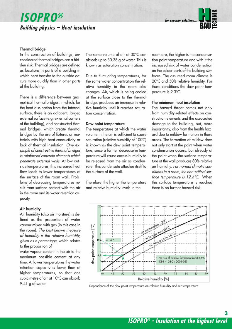
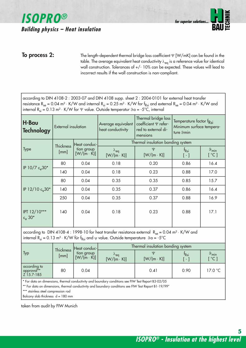
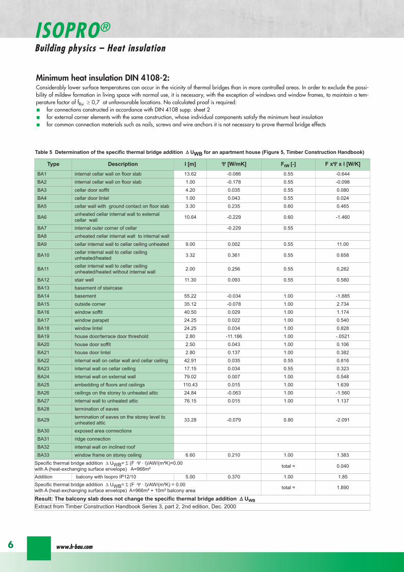
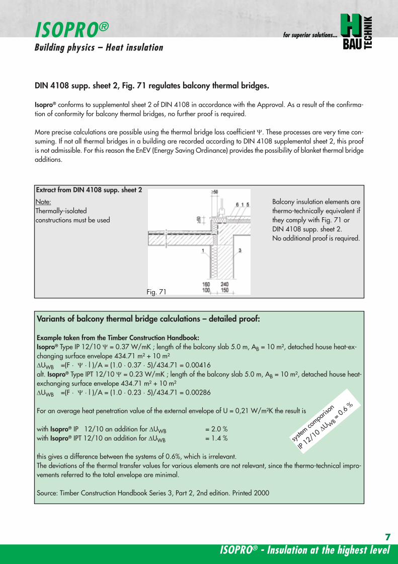
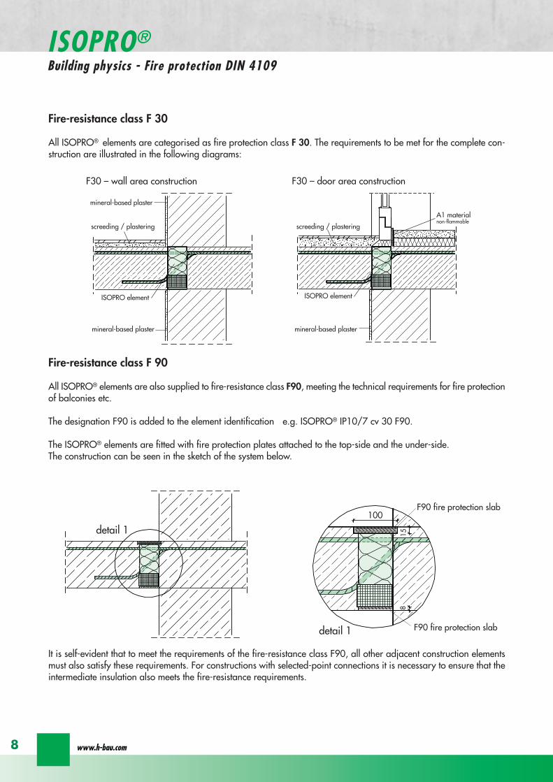
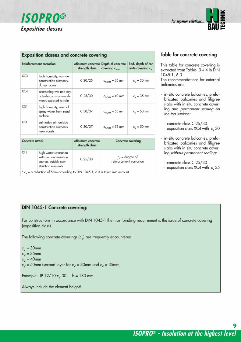
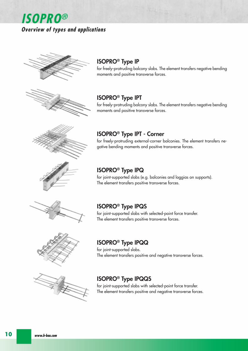
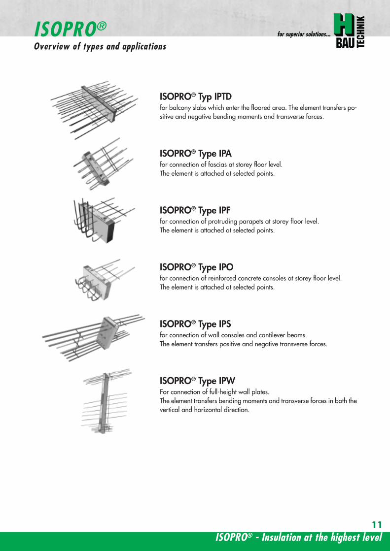
ISOPROreg - Insulation at the highest level
for superior solutions
11
ISOPROreg Typ IPTDfor balcony slabs which enter the floored area The element transfers po-sitive and negative bending moments and transverse forces
ISOPROreg Type IPAfor connection of fascias at storey floor level The element is attached at selected points
ISOPROreg Type IPFfor connection of protruding parapets at storey floor levelThe element is attached at selected points
ISOPROreg Type IPOfor connection of reinforced concrete consoles at storey floor level The element is attached at selected points
ISOPROreg Type IPSfor connection of wall consoles and cantilever beams The element transfers positive and negative transverse forces
ISOPROreg Type IPWFor connection of full-height wall plates The element transfers bending moments and transverse forces in both thevertical and horizontal direction
ISOPROreg
Overview of types and applications
Example of order code using element structural dataBalcony slab thickness h = 180 mmConcrete covering cv = 35 mm
mEd = 316 kNmmvEd = 514 kNm
Fire protection requirement F90
IP 1210 CV35 Q10 F90 h180
Type
load b
earing capacity
Concrete covering
supp transverse force
Fire protection F90
height of elem
ent
For types IPQ and IPQS no additional identification for theconcrete covering cv is required
Installation locations for ISOPROreg balcony insulation elements
ISOPROreg in single-skin brickwork ISOPROreg in single-skin brickwork with Thermal Insulation Bonding System
ISOPROreg in double-skin brickwork ISOPROreg in double-skin brickwork with rear ventilation
Order codes for ISOPROreg balcony insulation elements
variant lll HV lArrlArr ceiling offset upwardsvariant lll UV lArrlArr ceiling offset downwards
Additional identification for special element type IP
downward curve in the wall rArrrArr variant lupward curve in the wall rArrrArr variant ll
Sample order IP 127 varl CV35 h200
wwwh-baucom12
ISOPROreg
Order Codes and Installation Locations
IP IPT IP IPT
IP I
PT 2nd p
ositio
nIP IPT 2nd position
IP IPT IP IPT
IP IPT IPT Corner
IPT
Cor
ner
IP
IPT
IP IPT IP orIPT 1st position
IP
IPT
2nd
posi
tion
IP orIPT 1st position
Freely-protruding balcony
Side-separated internal corner balcony Internal-corner balcony
Internal-corner balconyloggia overlying on 3 sidespartially projecting
External corner balcony
ISOPROreg - Insulation at the highest level
for superior solutions
13
ISOPROreg Type IP IPTExamples
balcony side slab side
balcony side slab side
Dimensions Type IP [length in mm]
TypeTension rod Transverse force rod Supplemental transverse force
ZL QL Q8L Q10L Q12LIP 88 560 297 497 - -IP 107 690 297 497 - -IP 108 560 337 497 617 742IP 127 690 337 497 617 742IP 128 690 337 497 617 742IP 129 690 337 497 617 742IP 1210 690 337 497 617 742
Top view
section IP
section IP - X
Expansion joint spacing for ISOPROreg Type IP can be found on page 24
Configuration of the elements
Type Length of element [mm] Tension rods Transverse force rodstandard X-variation
Compression blocks
IP 88 1000 8 Oslash 8 4 Oslash 6 8 Oslash 6 4IP 107 1000 6 Oslash 8 + 2 Oslash10 4 Oslash 6 8 Oslash 6 4IP 108 1000 10 Oslash 8 4 Oslash 8 8 Oslash 8 4IP 127 1000 9 Oslash 10 4 Oslash 8 8 Oslash 8 6IP 128 1000 10 Oslash 10 4 Oslash 8 8 Oslash 8 6IP 129 1000 11 Oslash 10 4 Oslash 8 8 Oslash 8 7IP 1210 1000 12 Oslash 10 4 Oslash 8 8 Oslash 8 8
wwwh-baucom
ISOPROreg Type IPConstruction and dimensions
14
Type certificateNr 0517
Buildings InspectorateapprovalNr Z-157-244
1000
20
20
balcony slab
balcony slab
Dimensions Type IPT [length in mm]
TypeTension rod Transverse force rod Compression rods Supplemental transverse force
ZL QL DL Q10L Q12L Q14LIPT 1211 820 382 165 472 572 662IPT 1212 820 382 165 472 572 662IPT 1412 820 382 165 472 572 662IPT 1414 960 382 200 472 572 662
Top view
section IPT
Expansion joint spacing for ISOPROreg Type IPT can be found on page 24
Configuration of the elements
Type Length of element [mm] Tension rods Transverse force rodstandard X-variation
Compression rods
IPT 1211 500 + 500 6 Oslash 10 + 4 Oslash12 4 Oslash 8 8 Oslash 8 6x2 Oslash 10 + 4x2 Oslash12IPT 1212 500 + 500 10 Oslash 12 4 Oslash 8 8 Oslash 8 10x2 Oslash 12IPT 1412 500 + 500 12 Oslash 12 4 Oslash 8 8 Oslash 8 10x2 Oslash 14IPT 1414 500 + 500 10 Oslash 14 4 Oslash 8 8 Oslash 8 10x2 Oslash 14
ISOPROreg - Insulation at the highest level
for superior solutions
15
ISOPROreg Type IPTConstruction and dimensions
section IPT - X
Type certificateNr 0518
Buildings InspectorateapprovalNr Z-157-243
Types with increased transverse-force load capacity
Type IP 88Q
IP 107Q
IP 108Q
IP 127Q
IP 128Q
Rated values for transverse-force loading vRd [kNm]
Q8 (4Oslash8) h ge 160mm 618Q10 (4Oslash10) h ge 170mm 966Q12 (4Oslash12) h ge 180mm 1391
Plate thickness [cm] with re-ference to cv [mm] Rated values for moment loading mRd [kNmm]
30 35 40 45 50 IP 88 IP 107 IP 108 IP 127 IP 128
- - - - 16 103 124 137 192 203- - - 16 - 110 132 145 204 216- - 16 - 17 116 140 154 216 229- 16 - 17 - 123 148 163 228 24216 - 17 - 18 129 156 172 240 255- 17 - 18 - 136 164 181 252 26817 - 18 - 19 142 171 189 264 281- 18 - 19 - 148 179 198 276 29418 - 19 - 20 154 187 206 289 306- 19 - 20 - 161 195 215 301 31919 - 20 - 21 167 203 223 313 332- 20 - 21 - 174 211 232 325 34520 - 21 - 22 180 219 240 337 358- 21 - 22 - 187 227 249 349 37121 - 22 - 23 193 234 257 361 384- 22 - 23 - 200 242 266 373 39722 - 23 - 24 206 250 275 386 409- 23 - 24 - 213 258 284 398 42223 - 24 - 25 219 266 292 410 435- 24 - 25 - 226 274 301 422 44824 - 25 - - 232 282 309 434 461- 25 - - - 239 289 318 446 47425 - - - - 245 297 326 458 486
Rated values for transverse-force loading vRd [kNm]h = 160 - 250 [mm] 275 275 415 415 415
Rated values for transverse-force loading vRd [kNm]
Type IP 88 IP 107 IP 108 IP 127 IP 128X plusmn275 plusmn415
Q8X + 618 - 488Q10X + 966 - 696Q12X + 1391 - 696
wwwh-baucom
ISOPROreg
Dimensioning table for concrete gege C2025
16
Types with positive and negative transverse-force capacity
IP 129Q
IP 1210Q
IPT 1211Q
IPT 1212Q
IPT1412Q
IPT1414Q
Rated values for transverse-force loading vRd [kNm]
6189661391
Rated values for moment loading mRd [kNmm]
IP 129 IP 1210 IPT1211 IPT1212 IPT1412 IPT1414
234 255 283 319 368 439249 272 301 339 391 468264 288 319 360 415 497279 304 337 380 439 526293 320 356 401 463 555308 336 374 421 486 584323 352 392 442 510 613338 369 410 462 534 642353 385 428 482 558 671367 401 446 503 582 699382 417 464 523 606 728397 433 482 544 629 757412 449 501 564 653 786427 466 519 585 677 815441 482 537 605 701 844456 498 555 625 725 873471 514 573 646 749 902486 540 591 666 773 931501 566 609 687 796 960516 573 628 707 820 988530 579 646 728 844 1017545 595 664 748 868 1046560 611 682 769 892 1075
Rated values for transverse-force loading vRd [kNm]415 415 415 415 415 415
Rated values for transverse-force loading vRd [kNm]
IP 129 IP 1210 IPT 1211 IPT 1212 IPT 1412 IPT 1414plusmn415
+ 618 - 488+ 966 - 696+ 1391 - 696
ISOPROreg - Insulation at the highest level
for superior solutions
17
ISOPROreg
Dimensioning table for concrete gege C2025
balcony slab
Section A - A
AA
a
aa
b
c
b
c
c
c
b
b
tension rod ISOPRO
compression support ISOPROtransverse force bars ISOPRO
integral suspension reinforcement upper reinforcement of steel bars or mesh
lower reinforcement of steel bars or mesh
insert stirrup Oslash 8
d
d secondary reinforcement Oslash 8
concrete concrete
100
mesh support
floor balcony
1 Lay the lower reinforcement for the floor slab2 Install ISOPROreg IP and align The direction of alignment
(arrow symbol on top of element) must be followed3 Insert the edging (in accordance with DIN 1045-1) and
the upper floor reinforcement and bind together withthe ISOPROreg tension rods The ISOPROreg tension rodsand the support reinforcement are at the same level Ifrequired the binder on the tension rod level can be cutthrough
4 Lay the lower reinforcement and the edging for thebalcony slab in accordance with DIN 1045-1
5 Lay the balcony-side distribution rods one Oslash 8 top andbottom pos with insert stirrups pos separatedfrom the insulation body by approx 50 mm
6 Insert the upper floor reinforcement and bind to-gether with the ISOPROreg tension rods The ISOPROreg
tension rods and the support reinforcement are at thesame level
7 It is necessary when concreting to fill and pack uniformlyon both sides in order to prevent movement of the ISO-PROreg elements
ISOPROreg Type IP with on-site mesh supportThe mesh support replaces the suspension reinforce-ment It should be installed at a distance of le 100 mmfrom the insulation and raised up until it is immediatelybelow the tension reinforcement The diameter of thediagonals must be at least 5 mm The transverse forcerod can be positioned above or below the mesh sup-port
Since the contact pressure will be calculated as notgreater than fcd=085 middot fck γc no gap or edge ten-sioning reinforcement is required It is only necessaryto have edging on both sides of the insulation Thisshould be dimensioned for VRd
For indirect support of the ISOPROreg elements a suspensionreinforcement which is dimensioned for VRd is also re-quired on the floor side The bending reinforcement of thejoist must be according to structural calculations howeveras a minimum one Oslash 8 top and bottom is required
wwwh-baucom18
ISOPROreg Type IPOn-site reinforcement and installation instructions
balcony slab
upper reinforcement of steel bars or mesh
lower reinforcement of steel bars or mesh
insert stirrup Oslash 8A
Aa
b
c
a
c
b
section A - A
a
c
b
transverse force bars ISOPRO compression strut ISOPRO
integral suspension reinforcement tension rod ISOPRO
d
d
b
c
concrete concrete
secondary reinforcement Oslash 8
1 Lay the lower reinforcement for the floor slab2 Install ISOPROreg IPT and align The direction of alignment (arrow symbol on top of element) must be followed3 Insert the edging (in accordance with DIN 1045-1) and the upper floor reinforcement and bind together with the
ISOPROreg tension rods The ISOPROreg tension rods and the support reinforcement are at the same level If requiredthe binder on the tension rod level can be cut through
4 Lay the lower reinforcement and the edging for the balcony slab in accordance with DIN 1045-15 Lay the balcony-side distribution rods one Oslash 8 top and bottom pos with insert stirrups pos separated from
the insulation body by approx 50 mm6 Insert the upper floor reinforcement and bind together with the ISOPROreg tension rods The ISOPROreg tension rods
and the support reinforcement are at the same level7 It is necessary when concreting to fill and pack uniformly on both sides in order to prevent movement of the ISOPROreg
elements
For indirect support of the ISOPROreg elements a suspension reinforcement which is dimensioned for VRd is also requiredon the floor side The bending reinforcement of the joist must be according to structural calculations however as a mi-nimum one Oslash 8 top and bottom is required
Since the contact pressure will be calculated as not greater than fcd=085 middot fck γc no gap or edge tensioning rein-forcement is required It is only necessary to have edging on both sides of the insulation This should be dimensionedfor VRd
ISOPROreg - Insulation at the highest level
ISOPROreg Type IPTOn-site reinforcement and installation instructions
for superior solutions
19
ISOPROreg Type IPOn-site reinforcement and installation instructions
balcony
slab
wall
balcony
h lt
80
ab
c
a
b
c
aa
a
a
b
c
b
c
a
a
bb
a
c
c
ee
d
d
b
b
upper reinforcement of steel bars or mesh
lower reinforcement of steel bars or mesh
closed stirrup
inse
rt s
tirru
p
reinforcement
upper reinforcement of steel bars or mesh
lower reinforcement of steel bars or mesh
closed stirrup
upper reinforcement of steel bars or mesh
lower reinforcement of steel bars or mesh
clos
ed s
tirru
p
insert stirrup
parallel reinforcement
ain
sert
stir
rup
b
reinforcementb
wall
balcony wall
balcony
slab
balcony
slab
ndash If the height offset is less than 80 mm a standardelement can also be used
ndash In this case a stirrup reinforcement with an upper leglength gt ls is required to deflect the tensile force onthe floor side
ndash Dimensioning the stirrup reinforcement for the can-tilever effects and transverse forces from the balcony
slabndash For connection reinforcement on the balcony side see
page 1819ndash The necessary transverse reinforcement in the overlap
area must be proved in accordance with DIN 1045-1ndash Recommended joist width at least 200 mm
Connection to a ldquomarginallyrdquo height-offset floor slab
balcony
slab
wall
balcony
h lt
80
ab
c
a
b
c
a
a
a
a
b
c
b
c
a
a
bb
a
c
c
ee
d
d
b
b
upper reinforcement of steel bars or mesh
lower reinforcement of steel bars or mesh
closed stirrup
inse
rt s
tirru
p
reinforcement
upper reinforcement of steel bars or mesh
lower reinforcement of steel bars or mesh
closed stirrup
upper reinforcement of steel bars or mesh
lower reinforcement of steel bars or mesh
clos
ed s
tirru
p
insert stirrup
parallel reinforcement
ain
sert
stir
rup
b
reinforcementb
wall
balcony wall
balcony
slab
balcony
slab
ndash The ISOPROreg tension rods comply with the necessaryoverlap length ls given in DIN 1045-1
ndash For connection reinforcement on the balcony side seepage 1819
ndash The necessary transverse reinforcement in the overlaparea must be proved in accordance with DIN 1045-1
ndash The minimum wall thickness is dependent on the type
Connection to a vertical wall ndash connection downwards
balcony
slab
wall
balcony
h lt
80
ab
c
a
b
c
a
a
a
a
b
c
b
c
a
a
bb
a
c
c
ee
d
d
b
b
upper reinforcement of steel bars or mesh
lower reinforcement of steel bars or mesh
closed stirrup
inse
rt s
tirru
p
reinforcement
upper reinforcement of steel bars or mesh
lower reinforcement of steel bars or mesh
closed stirrup
upper reinforcement of steel bars or mesh
lower reinforcement of steel bars or mesh
clos
ed s
tirru
p
insert stirrup
parallel reinforcement
ain
sert
stir
rup
b
reinforcementb
wall
balcony wall
balcony
slab
balcony
slab
ndash The ISOPROreg tension rods comply with the necessaryoverlap length ls given in DIN 1045-1
ndash For connection reinforcement on the balcony side seepage 1819
ndash The necessary transverse reinforcement in the overlaparea must be proved in accordance with DIN 1045-1
ndash The minimum wall thickness is dependent on the type
Connection to a vertical wall ndash connection upwards
wwwh-baucom20
ISOPROreg
Special types Valid for type series IP and IPT (analogously)
balcony
slab
wall
balcony
h lt
80
ab
c
a
b
c
a
a
a
a
b
c
b
c
a
a
bb
a
c
c
ee
d
d
b
b
upper reinforcement of steel bars or mesh
lower reinforcement of steel bars or mesh
closed stirrup
inse
rt s
tirru
p
reinforcement
upper reinforcement of steel bars or mesh
lower reinforcement of steel bars or mesh
closed stirrup
upper reinforcement of steel bars or mesh
lower reinforcement of steel bars or mesh
clos
ed s
tirru
p
insert stirrup
parallel reinforcement
ain
sert
stir
rup
b
reinforcementb
wall
balcony wall
balcony
slab
balcony
slab
ndash dimensioning of the stirrup reinforcement for can-tilever effect and transverse force on the balcony slab
ndash the ISOPROreg tension rods comply with the DIN 1045-1 requirement for overlap length ls
ndash for on-site reinforcement see pages 1819
ndash the required transverse reinforcement in the overlapzone must be proven in compliance with DIN 1045-1
ndash recommended step-down width at least 220 mm
Connection to a floor slab with a step-up offset
balcony
slab
wall
balcony
h lt
80
ab
c
a
b
c
a
a
a
a
b
c
b
c
a
a
bb
a
c
c
ee
d
d
b
b
upper reinforcement of steel bars or mesh
lower reinforcement of steel bars or mesh
closed stirrup
inse
rt s
tirru
p
reinforcement
upper reinforcement of steel bars or mesh
lower reinforcement of steel bars or mesh
closed stirrup
upper reinforcement of steel bars or mesh
lower reinforcement of steel bars or mesh
clos
ed s
tirru
p
insert stirrup
parallel reinforcementa
inse
rt s
tirru
p
b
reinforcementb
wall
balcony wall
balcony
slab
balcony
slab
ndash dimensioning of the stirrup reinforcement for can-tilever effect and transverse force on the balcony slab
ndash the ISOPROreg tension rods comply with the DIN 1045-1 requirement for overlap length ls
ndash for on-site reinforcement see pages 1819
ndash the required transverse reinforcement in the overlapzone must be proven in compliance with DIN 1045-1
ndash constructive angle reinforcement pos 3ndash recommended step-down width at least 220 mm
Connection to a floor slab with step-down offset
ISOPROreg - Insulation at the highest level
for superior solutions
21
ISOPROreg
Special types Valid for type series IP and IPT (analogously)
After stripping freely-protruding concrete slabs experience a lowering of the slab edge This displacement is a com-bination of the deformation of the balcony insulation elements used and the bending of the slab itself These two de-formations are superimposed and compensated by raising the formworkThe calculations shown below give the required formwork height offset at the end of the cantilever which results fromthe ISOPROreg elements at 100 loading For the total height offset the slab deformation should be added in accor-dance with DIN 1045-1 The total height offset defined in the construction plans from the structural design engineershould take into account the planned direction of the drainage when rounding off the results
wwwh-baucom22
ISOPROreg
Deflection and height offset
Element height h [mm] IP 88IP 107IP 108
IP 127IP 128IP 129
IP 1210
IPT 1211IPT 1212IPT 1412
IPT 1414Concrete covering cv
30 35 40 45 50160 051 059 092 106
160 048 056 087 100160 170 045 053 082 094
160 170 043 050 077 089160 170 180 041 047 073 084
170 180 039 045 070 080170 180 190 037 043 067 079
180 190 035 041 064 073180 190 200 034 039 061 069
190 200 033 038 059 067190 200 210 031 036 056 064
200 210 030 035 054 062200 210 220 029 034 052 059
210 220 028 033 050 057210 220 230 027 031 049 055
220 230 026 030 047 053220 230 240 026 029 046 052
230 240 025 029 044 050230 240 250 024 028 043 049
240 250 023 027 042 047240 250 023 026 040 046
250 022 025 039 045250 021 025 038 043
Offset height of the balcony slab
ISOPROreg - Insulation at the highest level
for superior solutionsISOPROreg
Deflection and height offset
Example for defining the balcony slab height offset
mEd bending moment used to determine the height offset resulting from the ISOPROreg elementThe definitive load combination is decided by the structural engineer
mRd design moment of the ISOPROreg element taken from the dimensioning table on pages 16 and 17lk Cantilever length in [m]
ExampleCantilever length lk = 180 mSlab thickness h = 180 mmIntrinsic weight (slab and covering) g = 60 kNm2
Edge load (parapet) F = 15 kNmLive load p = 40 kNm2
Concrete covering cv = 30 mm
Design calculationsmEd= (g + p) x lk2 2 + F x lk = (60 middot 135 + 40 middot 15) middot 182 2 + 15 middot 18 middot 135 = 265 kNmmvEd = (g + p) x lk + F = (60 middot 135 + 40 middot 15) middot 18 + 15 middot 135 = 274 kNm
Selected ISOPROreg IP 127 cv 30 h = 180 mm mRd = 289 kNmm vRd = 415 kNm
Selected load combination for determination of the height offset resulting from the ISOPROreg element mEd= (g + p3) middot lk22 + F middot lk= (60 middot 135 + 403 middot 15) middot 182 2 + 15 middot 18 middot 135 =200 kNmm
uuml = 041 middot (265 289) middot 180 middot 10 = 67 mm
23
uuml [mm] = value from table middot (mEdmRd) middot lk [m] middot 10
wwwh-baucom24
The external concrete components must have expansion joints at right angles to the insulation layer in order to limitthe stress caused by changes in temperature The spacing of the joints e is given in the following table
balcony
ISOPRO ISOPRO
expansion joint
balcony
e 2
e 2
ISOPRO Type IPT Corner
expansion joint
seperation ofexpansion joints e
seperation ofexpansion joints e
expansion jointExpansion joint spacing for ISOPROreg Types IP und IPT
Rod diameter [mm] le 10 12 14 16 20
Joint spacing e [m] 130 113 101 92 80
balcony
ISOPRO ISOPRO
expansion joint
balcony
e 2
e 2
ISOPRO Type IPT Corner
expansion joint
seperation ofexpansion joints e
seperation ofexpansion joints e
expansion joint
expansion joint dowellingeg HED-S + plastic sleeves
ISOPROreg
Expansion joint spacing
For corner constructions the maximum rod leg length is e2
ISOPROreg - Insulation at the highest level
for superior solutions
25
a a
b
c
b
c
sup3100
In pre-cast units
Arrange the lower reinforcement layer including themesh support as per structural design Distance to in-sulation joint le 100 mm (applies to IP only)
Install lower section The last transverse rod in themesh must be placed as close as possible to the insula-tion observing the required concrete covering
For IP the transverse force rod can be under or on topof the mesh The mesh support should be lifted until itis underneath the tension reinforcement
Concrete the slab element
Locate and fix the associated upper section andwhere required intermediate section
Type IP is supplied with suspension reinforcement asstandard
On-site
Lay the necessary on-site reinforcement on the floorside
Lay the slab element on the pre-prepared timberbeams
Lay the necessary on-site reinforcement on the bal-cony side
Attach the associated upper section and where re-quired intermediate section Bind the tension strutto the on-site reinforcement
h = 210 to 250 mm
Important note fit additional insertion stirrups Oslash 620 or stirrup meshQ188A on the balcony side
In type IP pre-cast units In type IPT pre-cast units
a a
b
c
b
c
sup3100
Type IP on-site Type IPT on-site
Important noteThe type identification for lower and upper sections must match (see also colour identification) The direction of in-stallation (on the balcony side) is mandatory
ISOPROreg
Two-part elements
wwwh-baucom26
upper section
centre section
lower section
upper section
centre section
lower section
balcony balconyslab slab
Type IP Type IPT
Construction
All ISOPROreg elements of types IP and IPT can be supplied as two-part elements
General notes
ndash The permitted resultant stresses can be found in thetables on pages 16 and 17 of this technical information
ndash Intermediate sections can be supplied for height offsetcompensation in 20 and 40 mm thicknesses
ndash Type IP If the mesh supports are placed with a spacingof le 100 mm from the insulation joint no additionalsuspension reinforcement is required Instead asuspension reinforcement dimensioned for VRd shouldbe located along the insulation joints
ndash For information regarding the required formwork height off-set and the maximum spacing of expansion joints refer topages 22 23 and 24
ndash The adhesive labels (type designation) for the upper andlower sections must be identical Follow the instructions forthe balcony side and the floor side
The following elements also have an addi-tional colour coding
ISOPROreg Type Colour code
IP 107 greenIP 127 blueIP 128 yellowIP 1210 white
The continuity of the colour coding throughthe elements ensures correct matching everytime even for short sections
ISOPROreg
Two-part elements
ISOPROreg - Insulation at the highest level
for superior solutions
27
balcony sidebalcony side
section 1st position
section 2nd position
slab balcony
1st position
2nd
posi
tion
cv
cvslab balcony
slab balcony
section 1st position
section 2nd position
1st position
2nd
posi
tion
slab balcony
IPT 127 Corner 820mmIPT 1210 Corner 960mm
IPT 127 Corner 820mmIPT 1210 Corner 960mm
IPT
127
Cor
ner
820m
mIP
T 12
10
Cor
ner
960m
mIP
T 12
7 C
orne
r82
0mm
IPT
121
0 C
orne
r96
0mm
General notes
Area of application for type IPT-Corner from slab thickness h le 180 mmOn-site reinforcement using overlap joints in accordance with DIN 1045-12001-07 Section 126Please refer to the information regarding on-site reinforcement on page 29Special elements for h = 160 mm are possibleBecause of the compression level a minimum spacing of the floor-side filigree slabs from the insulation body of185 mm is required for the ISOPROreg IPT-Corner elements
Type Length of element [m] Tension rods Compression level Transverse force rods
IPT 107-Corner 050 + 050 5 Oslash 10 + 5 Oslash 10 2 x 4 compression block 2 Oslash 10 + 2 Oslash 10
IPT 127-Corner 062 + 062 6 Oslash 12 + 6 Oslash 12 12 Oslash 14 + 12 Oslash 14 3 Oslash 10 + 3 Oslash 10
IPT 1210-Corner 062 + 062 6 Oslash 14 + 6 Oslash 14 14 Oslash 14 + 14 Oslash 14 3 Oslash 12 + 3 Oslash 12
Configuration of the elements
IPT 107-Corner
ISOPROreg Type IPT EckConstruction and dimensions
wwwh-baucom28
Plate thickness [mm] referred to cv [mm] Dimensional values for acceptable load moments MRd [kNm]
30 35 IPT 107 Corner IPT 127 Corner IPT 1210 Corner- 180 169 277 320
180 - 178 292 337- 190 186 306 354
190 - 195 320 370- 200 203 335 387
200 - 212 349 404- 210 220 363 421
210 - 229 378 437- 220 237 392 454
220 - 246 406 471- 230 254 421 487
230 - 263 435 504- 240 271 449 521
240 - 280 463 537- 250 289 478 554
250 - 297 492 571Dimensional values for acceptable transverse forces VRd [kN]
h = 180 - 250 [mm] 483 724 1043
balcony sidebalcony side
section 1st position
section 2nd position
slab balcony
1st position
2nd
posi
tion
cv
cvslab balcony
slab balcony
section 1st position
section 2nd position
1st position
2nd
posi
tion
slab balcony
IPT 127 Corner 820mmIPT 1210 Corner 960mm
IPT 127 Corner 820mmIPT 1210 Corner 960mm
IPT
127
Cor
ner
820m
mIP
T 12
10
Cor
ner
960m
mIP
T 12
7 C
orne
r82
0mm
IPT
121
0 C
orne
r96
0mm
Dimensioning table for concrete gege C2025
IPT 127-CornerIPT 1210-Corner
ISOPROreg Type IPT CornerConstruction and dimensions
ISOPROreg - Insulation at the highest level
for superior solutions
29
1st position
2nd
posi
tion
balcony slab
a
da
b b
c c
dstarter bar 1st position supplementary reinforcement
supplementary reinforcement
supp
lem
enta
ry r
einf
orce
men
t
supp
lem
enta
ry r
einf
orce
men
t
starter bar 1st position
stra
ter
bar
2nd
posi
tion
star
ter
bar
2nd
posi
tion
Type IPT 107-Corner IPT 127-Corner IPT 1210-Corner
starter bar 1st position 5 Oslash 10 6 Oslash 12 6 Oslash 14
starter bar 2nd position 5 Oslash 10 6 Oslash 12 6 Oslash 14
Supplementaryreinforcement 5 Oslash 10 6 Oslash 12 6 Oslash 14
Supplementaryreinforcement 5 Oslash 10 6 Oslash 12 6 Oslash 14
extension of the tension reinforcement internally as well as externally length = 2 x balcony cantilever length
ISOPROreg Type IPT CornerOn-site reinforcement
wwwh-baucom30
ISOPROreg - Insulation at the highest level
for superior solutions
IPQ IPQIPH
IPH
IPH
IPH
IPQS IPQSIPH IPQQS IPQQSIPH
IPQ IPQ
IPQ
IPQQ IPQQ
IPQQ IPQQIP
QS
IPQ IPQ
IPQ
Z
IPQ
S tie rod inlower position
IPQQ IPQQ
IPQ
Z
IPQ
S tie rod inlower position
propped balcony
internal-corner balcony with props
ISOPROreg
Examples of transverse force elements
propped balcony
propped balcony with selective point connection
internal-corner balcony with props
inset balcony with tieback3-sided overlying loggia with tieback
propped balcony with selective point connection
31
wwwh-baucom32
1000
1000
balcony slab balcony slab
IPQ 86 495 mmIPQ 88 495 mmIPQ 106 615 mmIPQ 126 740 mm
IPQ 86 495 mmIPQ 88 495 mmIPQ 106 615 mmIPQ 126 740 mm80
370 80 150
Calculated values for acceptable transverse forces vRd [kNm]
Element height IPQ 64 IPQ 65 IPQ 66 IPQ 68 IPQ 610
160 - 250 mm 348 435 522 695 869
Type IPQ 64 IPQ 65 IPQ 66 IPQ 68 IPQ 610Length [mm] 1000 1000 1000 1000 1000
Transverse force rods 4 Oslash 6 5 Oslash 6 6 Oslash 6 8 Oslash 6 10 Oslash 6
Compression blocks 4 4 4 4 4needed As [cmsup2] 08 10 12 16 20
Dimensioning table - Type IPQ for concrete gege C2025
Configuration of the elements Type IPQ
section
Top view
ISOPROreg Type IPQConstruction and dimensions
IPQ 64 - 610
min Element hight depentend on rod diameter Oslash 10 h ge170 Oslash 12 h ge180 Oslash 14 h ge190
ISOPROreg - Insulation at the highest level
for superior solutions
33
balcony slab
upper reinforcement of steel bars or mesh
lower reinforcement of steel bars or mesh
transverse shear force reinforcement 2 Oslash 8
insert stirrup
ls ls
a
b
c
d
d
a
c
d
b
suspension reinforcemente
ed
secondary reinforcement 2 Oslash 8
concrete concrete
The on-site suspension reinforcement pos and should be calculated for VRd (cf type test No 0519) and loca-ted next to the transverse force rods A Oslash 8 mm steel distribution rod should be installed above and below The sus-pension reinforcement can be replaced by a mesh support (see type IP page 18)DIN 1045-1 Section 1033 applies to the proof of the transverse force capacity of the slabs without shear reinforce-ment For proof of the transverse force capacity of the slabs with shear reinforcement DIN 1045-1 Section 1034 ap-plies The maximum transmissible transverse force across the joints must be limited to 03 VRdmax zu begrenzen
ISOPROreg Type IPQOn-site reinforcement
Calculated values for acceptable transverse forces vRd [kNm]
Element height IPQ 86 IPQ 88 IPQ 106 IPQ 125 IPQ 126
160 - 250 mm 927 1236 1449 1739 2089
Type IPQ 86 IPQ 88 IPQ 106 IPQ 125 IPQ 126Length [mm] 1000 1000 1000 1000 1000
Transverse force rods 6 Oslash 8 8 Oslash 8 6 Oslash 10 5 Oslash 12 6 Oslash 12
Compression blocks 4 4 4 4 4needed As [cmsup2] 21 28 33 40 48
Configuration of the elements Type IPQ
min Element hight depentend on rod diameter Oslash 10 h ge170 Oslash 12 h ge180 Oslash 14 h ge190
wwwh-baucom34
ISOPROreg Type IPQS 2Construction and dimensions
balcony slab
balcony slab
Calculated values for acceptable transverse forces VRd [kN]
Element height IPQS 62 IPQS 82 IPQS 102 IPQS 122 IPQS 142
160 - 250 mm 174 309 483 695 947
Dimensioning table - Type IPQS2 for concrete gege C2025
Type IPQS 62 IPQS 82 IPQS 102 IPQS 122 IPQS 142
Element length [mm] 300 300 300 300 300
Transverse force rods 2 Oslash 6 2 Oslash 8 2 Oslash 10 2 Oslash 12 2 Oslash 14
Compression rods 2 Oslash 10 2 Oslash 10 3 Oslash 10 4 Oslash 12 4 Oslash 14needed As [cmsup2] 040 071 111 160 218
Configuration of the elements Type IPQS2
min Element height dependent on rod diameter Oslash 10 h ge170 Oslash 12 h ge180 Oslash 14 h ge190
IPQS 82 495mmIPQS102 615mmIPQS122 740mmIPQS 142 860mm
IPQS 62
IPQS 82 495mmIPQS102 615mmIPQS122 740mmIPQS 142 860mm
ISOPROreg - Insulation at the highest level
for superior solutions
35
Calculated values for acceptable transverse forces VRd [kN]
Element height IPQS 63 IPQS 83 IPQS 103 IPQS 123 IPQS 143
160 - 250 mm 261 464 724 1043 1420
Dimensioning table - Type IPQS3 for concrete gege C2025
Type IPQS 63 IPQS 83 IPQS 103 IPQS 123 IPQS 143
Element length [mm] 400 400 400 400 400
Transverse force rods 3 Oslash 6 3 Oslash 8 3 Oslash 10 3 Oslash 12 3 Oslash 14
Compression rods 2 Oslash 10 3 Oslash 10 4 Oslash 12 5 Oslash 12 6 Oslash 14needed As [cmsup2] 060 107 167 240 327
Configuration of the elements Type IPQS3
balcony slab
balcony slab
ISOPROreg Type IPQS 3Construction and dimensionsn
IPQS 83 495mmIPQS103 615mmIPQS123 740mmIPQS 143 860mm
IPQS 63
IPQS 83 495mmIPQS103 615mmIPQS123 740mmIPQS 143 860mm
min Element height dependent on rod diameter Oslash 10 h ge170 Oslash 12 h ge180 Oslash 14 h ge190
wwwh-baucom36
ISOPROreg Type IPQQConstruction and dimensions
1000
1000
balcony balconyslab slab
180 80 150 80165 165
370 80 80150
IPQQ 86 495 mmIPQQ 106 615 mmIPQQ 126 740 mm
IPQQ 86 495 mmIPQQ 106 615 mmIPQQ 126 740 mm
IPQQ 64 IPQQ 66IPQQ 68 IPQQ 610
Calculated values for acceptable transverse forces vRd [kNm]
Element height IPQQ 64 IPQQ 66 IPQQ 68 IPQQ 610 IPQQ 86 IPQQ 106 IPQQ 126
160 - 250 mm plusmn348 plusmn522 plusmn695 plusmn869 plusmn927 plusmn1449 plusmn2086
Type IPQQ 64 IPQQ 66 IPQQ 68 IPQQ 610 IPQQ 86 IPQQ 106 IPQQ 126Element length [mm] 500 + 500 500 + 500 500 + 500 500 + 500 500 + 500 500 + 500 500 + 500Transverse force rods 2x4 Oslash 6 2x6 Oslash 6 2x8 Oslash 6 2x10 Oslash 6 2x6 Oslash 8 2x6 Oslash 10 2x6 Oslash 12
Compression rods 4 Oslash 10 4 Oslash 10 6 Oslash 10 6 Oslash 10 6 Oslash 10 10 Oslash 10 10 Oslash 12needed As [cmsup2] 080 120 160 200 213 333 480
Dimensioning table - Type IPQQ for concrete gege C2025
Configuration of the elements Typ IPQQ
Top view
Section
min Element height dependent on rod diameter Oslash 10 h ge170 Oslash 12 h ge180 Oslash 14 h ge190
ISOPROreg - Insulation at the highest level
for superior solutions
37
ISOPROreg Type IPQQOn-site reinforcement
balcony slab
upper reinforcement of steel bars or mesh
lower reinforcement of steel bars or mesh
ls ls
b
c
a
c
d
b
insert stirrupa
d
dinsert stirrupa
ad
d
secondary reinforcement 2 Oslash 8
concrete concrete
secondary reinforcement 2 Oslash 8
The on-site suspension reinforcement pos should be calculated for VRd and located next to the transverse forcerods A Oslash 8 mm steel distribution rod should be installed above and below DIN 1045-1 Section 1033 applies to the proof of the transverse force capacity of the slabs without shear reinforce-ment For proof of the transverse force capacity of the slabs with shear reinforcement DIN 1045-1 Section 1034 ap-plies The maximum transmissible transverse force across the joints must be limited to 03 VRdmax
wwwh-baucom38
ISOPROreg Type IPQQS 2Construction and dimensions
balcony slab
balcony slab
Calculated values for acceptable transverse forces VRd [kN]
Element height IPQQS 62 IPQQS 82 IPQQS 102 IPQQS 122 IPQQS 142
160 - 250 mm plusmn174 plusmn309 plusmn483 plusmn695 plusmn947
Dimensioning table - Type IPQQS2 for concrete gege C2025
Type IPQQS 62 IPQQS 82 IPQQS 102 IPQQS 122 IPQQS 142
Element length [mm] 300 300 300 300 300
Transverse force rods 2x 2 Oslash 6 2x 2 Oslash 8 2x 2 Oslash 10 2x 2 Oslash 12 2x 2 Oslash 14
Compression rods 2 Oslash 10 2 Oslash 10 3 Oslash 10 4 Oslash 12 4 Oslash 14needed As [cmsup2] 040 071 111 160 218
Configuration of the elements Type IPQQS2
IPQQS 82 495mmIPQQS 102 615mmIPQQS 122 740mmIPQQS 142 860mm
IPQQS 62
IPQQS 82 495mmIPQQS 102 615mmIPQQS 122 740mmIPQQS 142 860mm
min Element height dependent on rod diameter Oslash 10 h ge170 Oslash 12 h ge180 Oslash 14 h ge190
ISOPROreg - Insulation at the highest level
for superior solutions
39
ISOPROreg Type IPQQS 3Construction and dimensions
balcony slab
balcony slab
Calculated values for acceptable transverse forces VRd [kN]
Element height IPQQS 63 IPQQS 83 IPQQS 103 IPQQS 123 IPQQS 143
160 - 250 mm plusmn261 plusmn464 plusmn724 plusmn1043 plusmn1420
Dimensioning table - Type IPQQS3 for concrete gege C2025
Type IPQQS 63 IPQQS 83 IPQQS 103 IPQQS 123 IPQQS 143
Element length [mm] 400 400 400 400 400
Transverse force rods 2x 3 Oslash 6 2x 3 Oslash 8 2x 3 Oslash 10 2x 3 Oslash 12 2x 3 Oslash 14
Compression rods 2 Oslash 10 3 Oslash 10 4 Oslash 12 5 Oslash 12 6 Oslash 14needed As [cmsup2] 060 107 167 240 327
Configuration of the elements Type IPQQS3
min Element height dependent on rod diameter Oslash 10 h ge170 Oslash 12 h ge180 Oslash 14 h ge190 alternatively in Element length 500 mm available
IPQQS 83 495mmIPQQS 103 615mmIPQQS 123 740mmIPQQS 143 860mm
IPQQS 63
IPQQS 83 495mmIPQQS 103 615mmIPQQS 123 740mmIPQQS 143 860mm
wwwh-baucom40
ISOPROreg Type IPTDConstruction and dimensions
IPTD IPTD
inset balcony
30
balcony slab
Top view
Section
Example
Table of Dimensions ndash Type IPTD [length in mm]
TypeTension rod Transverse force rod Compression rod Supplemental transverse force
ZL QL DL Q10L Q12LIPTD 126 820 497 820 617 742IPTD 127 820 497 820 617 742IPTD 1210 820 497 820 617 742IPTD 1212 820 497 820 617 742IPTD 1410 960 497 960 617 742
ISOPROreg - Insulation at the highest level
for superior solutions
41
ISOPROreg Type IPTDOn-site reinforcement
balcony slab
upper reinforcement of steelbars or mesh
lower reinforcement of steelbars or mesh
secondary reinforcement 2 Oslash 8
secondary reinforcement 2 Oslash 8
insert stirrup
ls ls
AA
a
b
c
d
d
a
c
d
b
lower reinforcement of steelbars or meshc
upper reinforcement of steelbars or meshb
d
insert stirrupee
b
c
a
a
Section A - A
ISOPRO transverse force rods ISOPRO compression rods
ISOPRO transverse force rods ISOPRO tension rods
d
concrete concrete
The on-site suspension reinforcement pos should be calculated for VRd and located next to the transverse forcerods A Oslash 8 mm steel distribution rod should be installed above and below DIN 1045-1 Section 1033 applies to the proof of the transverse force capacity of the slabs without shear reinforce-ment For proof of the transverse force capacity of the slabs with shear reinforcement DIN 1045-1 Section 1034 ap-plies The maximum transmissible transverse force across the joints must be limited to 03 VRdmax
wwwh-baucom42
ISOPROreg Type IPTDDimensioning table for concrete gege C2025
Plate thickness [mm] withreference to cv [mm] Rated values for moment loading mRd [kNmm]
30 35 IPTD 126IPTD 126
Q10IPTD 126
Q12IPTD 127
IPTD 127Q10
IPTD 127Q12
IPTD 1210
- 160 plusmn 145 - - plusmn 182 - - plusmn 253160 - plusmn 154 - - plusmn 193 - - plusmn 269- 170 plusmn 162 plusmn 146 - plusmn 204 plusmn 187 - plusmn 284
170 - plusmn 171 plusmn 154 - plusmn 214 plusmn 197 - plusmn 299- 180 plusmn 180 plusmn 162 plusmn 145 plusmn 225 plusmn 208 plusmn 190 plusmn 314
180 - plusmn 189 plusmn 170 plusmn 152 plusmn 236 plusmn 218 plusmn 199 plusmn 330- 190 plusmn 197 plusmn 178 plusmn 159 plusmn 247 plusmn 228 plusmn 209 plusmn 345
190 - plusmn 206 plusmn 186 plusmn 166 plusmn 258 plusmn 238 plusmn 218 plusmn 360- 200 plusmn 215 plusmn 194 plusmn 173 plusmn 269 plusmn 248 plusmn 227 plusmn 375
200 - plusmn 223 plusmn 202 plusmn 180 plusmn 280 plusmn 258 plusmn 236 plusmn 391- 210 plusmn 232 plusmn 209 plusmn 187 plusmn 291 plusmn 268 plusmn 246 plusmn 406
210 - plusmn 241 plusmn 217 plusmn 194 plusmn 302 plusmn 278 plusmn 255 plusmn 421- 220 plusmn 250 plusmn 225 plusmn 201 plusmn 313 plusmn 288 plusmn 264 plusmn 437
220 - plusmn 258 plusmn 233 plusmn 208 plusmn 324 plusmn 298 plusmn 273 plusmn 452- 230 plusmn 267 plusmn 241 plusmn 215 plusmn 335 plusmn 308 plusmn 283 plusmn 467
230 - plusmn 276 plusmn 249 plusmn 222 plusmn 346 plusmn 318 plusmn 292 plusmn 482- 240 plusmn 285 plusmn 257 plusmn 229 plusmn 357 plusmn 328 plusmn 301 plusmn 498
240 - plusmn 293 plusmn 265 plusmn 236 plusmn 368 plusmn 339 plusmn 310 plusmn 513- 250 plusmn 302 plusmn 272 plusmn 243 plusmn 379 plusmn 349 plusmn 320 plusmn 528
250 - plusmn 311 plusmn 280 plusmn 250 plusmn 390 plusmn 359 plusmn 329 plusmn 543
Rated values for transverse force loading vRd [kNm]
h = 160 - 250 [mm ] plusmn 415 plusmn 762 plusmn 1098 plusmn 415 plusmn 762 plusmn 1098 plusmn 415
Type IPTD 126 IPTD 126Q10
IPTD 126Q12
IPTD 127 IPTD 127Q10
IPTD 127Q12
IPTD 1210
Element lenght [mm] 500 + 500 500 + 500 500 + 500 500 + 500 500 + 500 500 + 500 500 + 500
Tension rods 6 Oslash 12 6 Oslash 12 6 Oslash 122 Oslash 10 + 6 Oslash 12
2 Oslash 10 + 6 Oslash 12
2 Oslash 10 +6 Oslash 12
10 Oslash 12
Transverse forcerods
2x4 Oslash 8 2x4 Oslash 10 2x4 Oslash 12 2x4 Oslash 8 2x4 Oslash 10 2x4 Oslash 12 2x4 Oslash 8
Compression rods 6 Oslash 12 6 Oslash 12 6 Oslash 122 Oslash 10 + 6 Oslash 12
2 Oslash 10 +6 Oslash 12
2 Oslash 10 +6 Oslash 12
10 Oslash 12
Configuration of the elements Type IPTD
ISOPROreg - Insulation at the highest level
for superior solutions
43
ISOPROreg Type IPTDDimensioning table for concrete gege C2025
Rated values for moment loading mRd [kNmm]
IPTD 1210Q10
IPTD 1210Q12
IPTD 1212IPTD 1212
Q10IPTD 1212
Q12IPTD 1410
IPTD 1410Q10
IPTD 1410Q12
- - plusmn 307 - - plusmn 349 - -- - plusmn 326 - - plusmn 371 - -
plusmn 268 - plusmn 345 plusmn 328 - plusmn 392 plusmn 377 -plusmn 282 - plusmn 363 plusmn 346 - plusmn 414 plusmn 397 -plusmn 297 plusmn 279 plusmn 382 plusmn 364 plusmn 346 plusmn 436 plusmn 418 plusmn 401plusmn 311 plusmn 293 plusmn 400 plusmn 381 plusmn 363 plusmn- 457 plusmn 439 plusmn 421plusmn 325 plusmn 306 plusmn 419 plusmn 399 plusmn 380 plusmn 479 plusmn 459 plusmn 441plusmn 340 plusmn 320 plusmn 437 plusmn 417 plusmn 397 plusmn 500 plusmn 480 plusmn 461plusmn 354 plusmn 333 plusmn 456 plusmn 434 plusmn 414 plusmn 522 plusmn 501 plusmn 480plusmn 369 plusmn 347 plusmn 474 plusmn 452 plusmn 430 plusmn 543 plusmn 522 plusmn 500plusmn 383 plusmn 361 plusmn 493 plusmn 470 plusmn 447 plusmn 565 plusmn 542 plusmn 520plusmn 397 plusmn 374 plusmn 511 plusmn 487 plusmn 464 plusmn 587 plusmn 563 plusmn 540plusmn 412 plusmn 388 plusmn 530 plusmn 505 plusmn 481 plusmn 608 plusmn 584 plusmn 560plusmn 426 plusmn 401 plusmn 548 plusmn 523 plusmn 498 plusmn 630 plusmn 604 plusmn 580plusmn 440 plusmn 415 plusmn 567 plusmn 540 plusmn 515 plusmn 351 plusmn 625 plusmn 600plusmn 455 plusmn 428 plusmn 585 plusmn 558 plusmn 531 plusmn 673 plusmn 646 plusmn 619plusmn 469 plusmn 442 plusmn 604 plusmn 576 plusmn 548 plusmn 694 plusmn 666 plusmn 639plusmn 484 plusmn 455 plusmn 622 plusmn 593 plusmn 565 plusmn 716 plusmn 687 plusmn 659plusmn 498 plusmn 469 plusmn 641 plusmn 611 plusmn 582 plusmn 737 plusmn 708 plusmn 679plusmn 512 plusmn 483 plusmn 659 plusmn 629 plusmn 599 plusmn 759 plusmn 728 plusmn 699
Rated values for transverse force loading vRd [kNm]
plusmn 762 plusmn 1098 plusmn 415 plusmn 762 plusmn 1098 plusmn 415 plusmn 762 plusmn 1098
IPTD 1210Q10
IPTD 1210Q12
IPTD 1212 IPTD 1212Q10
IPTD 1212Q12
IPTD 1410 IPTD 1410Q10
IPTD 1410Q12
500 + 500 500 + 500 500 + 500 500 + 500 500 + 500 500 + 500 500 + 500 500 + 500
10 Oslash 12 10 Oslash 12 12 Oslash 12 12 Oslash 12 12 Oslash 12 10 Oslash 14 10 Oslash 14 10 Oslash 14
2x4 Oslash 10 2x4 Oslash 12 2x4 Oslash 8 2x4 Oslash 10 2x4 Oslash 12 2x4 Oslash 8 2x4 Oslash 10 2x4 Oslash 12
10 Oslash 12 10 Oslash 12 12 Oslash 12 12 Oslash 12 12 Oslash 12 10 Oslash 14 10 Oslash 14 10 Oslash 14
wwwh-baucom44
ISOPROreg Type IPQZConstruction and dimensions
300
40
0
300
40
0
balcony slab
balcony slab
For restraint-free support with an IPQZ element it should be opposed by an IPQS element Both elements should bereinforced by a tieback which corresponds in diameter and rod count to the IPQS and IPQZAn on-site stirrup reinforcement is required to connect IPQS to the floor
Calculated values for acceptable transverse forces VRd [kN]
Element height IPQZ 62 IPQZ 82 IPQZ 102 IPQZ 122 IPQZ 142
160 - 250 mm 174 309 483 695 947
IPQZ 63 IPQZ 83 IPQZ 103 IPQZ 123 IPQZ 143
160 - 250 mm 261 464 724 1043 1420
Dimensioning table ndash Type IPQZ for concrete ge C2025
Type IPQZ 62 IPQZ 82 IPQZ 102 IPQZ 122 IPQZ 142Element lenght [mm] 300 300 300 300 300
Transverse force rods 2 Oslash 6 2 Oslash 8 2 Oslash 10 2 Oslash 12 2 Oslash 14
Configuration of the elements
Type IPQZ 63 IPQZ 83 IPQZ 103 IPQZ 123 IPQZ 143Element length [mm] 400 400 400 400 400
Transverse force rods 3 Oslash 6 3 Oslash 8 3 Oslash 10 3 Oslash 12 3 Oslash 14
min Element height dependent on rod diameter Oslash 10 h ge170 Oslash 12 h ge180 Oslash 14 h ge190
IPQZ 82 83 495mmIPQZ102 103 615mmIPQZ122 123 740mmIPQZ 142 143 860mm
IPQZ 82 83 495mmIPQZ102 103 615mmIPQZ122 123 740mmIPQZ 142 143 860mm
IPQZ 62 63
ISOPROreg - Insulation at the highest level
for superior solutions
45
ISOPROreg Type IPQZOn-site reinforcement
Type Tieback Insert stirrup for use with
IPQZ 62 2 Oslash 6 1 Oslash 6 IPQS 62
IPQZ 82 2 Oslash 8 1 Oslash 8 IPQS 82
IPQZ 102 2 Oslash 10 1 Oslash 10 IPQS 102
IPQZ 122 2 Oslash 12 2 Oslash 8 IPQS 122
IPQZ 142 2 Oslash 14 2 Oslash 10 IPQS 142
tie roda
b
stirrup for anchering tie rodb
a
slab slabbalcony
Typ IPQZ Typ IPQS
Type Tieback Insert stirrup for use with
IPQZ 63 3 Oslash 6 2 Oslash 6 IPQS 63
IPQZ 83 3 Oslash 8 2 Oslash 8 IPQS 83
IPQZ 103 3 Oslash 10 2 Oslash 10 IPQS 103
IPQZ 123 3 Oslash 12 3 Oslash 8 IPQS 123
IPQZ 143 3 Oslash 14 3 Oslash 10 IPQS 143
wwwh-baucom46
ISOPROreg Type IPHConstruction and dimensions
The ISOPROreg elements type IPH which absorb horizontal forces must only be used with ISOPROreg cantilever slabs ortransverse force connections
The number of IPH elements to be used is defined by the structural engineer whereby the expansion joint spacing mustbe maintained
When using ISOPROreg IPH elements the force absorption of the line connection must be reduced by the ratio of thelength of the IPH elements to the total connection length as a percentage
independent of cvReinforcement Length of
element
HRd
Transverse force Horizontal Transverse force Horizontal
IPH 1 2 x 1 Oslash 8 - 100 mm plusmn 74 kN -IPH 2 - 1 Oslash 10 100 mm - plusmn181 kNIPH 3 2 x 1 Oslash 8 1 Oslash 10 100 mm plusmn 74 kN plusmn 181 kN
Dimensioning table ndash Type IPH for concrete gege C2025
balcony slab
balcony slab
balcony slab
balcony slab
balcony slab
balcony slab
100
100
100
250 80 250
250 80 250
250 80 250IPH 1 for absorption of horizontal forces parallel to the insulation joint
IPH 2 for absorption of horizontal forces perpendicular to the insulation joint
IPH 3 for absorption of horizontal forces parallel and perpendicular to the insulation joint
ISOPROreg - Insulation at the highest level
for superior solutions
47
ISOPROreg Type IPHOn-site reinforcement
The installation of the ISOPROreg IPH elements is analogous to the installation of the ISOPROreg cantilever slabs or trans-verse force connectionsThe number and positions of the elements are defined in the structural detail The elements must be fixed in their posi-tions
plate slab balcony slab
ls ls
lower reinforcement of steel bars or mesh
d
lower reinforcement of steel bars or mesh
upper reinforcement of steel bars or mesh
a
aa
dc
d
insert stirrup
a
b
c
secondary reinforcement Oslash 8
b
c c
insert stirrup
wwwh-baucom48
ISOPROreg Type IPAConstruction and calculation values
29
0204
0608
1012
1416
1820
2422
2628
0204
0608
1012
1416
1820
2224
2628
0 +10 +20 +30 +40 +50-10-20-30-40-50
dimensioning axis
MEd
VEd
NEd
380
60
gt160
sup3 16
0
130
Section
Mathematical model ndash Static system Interaction diagram
NRd [kN]
M Rd[kNm]
DimensionsLength of element 350 mmFascia thickness 160 ndash 240 mmHeight of element from 160 mmThickness of insulation element 60 mm
ReinforcementTension rods 3 Oslash 8Compression rods 3 Oslash 8Transverse force rods 2 x 2 Oslash 6
Calculated values for NRd = 0MRd 29 kNmelementVRd plusmn 127 kNelement
ISOPROreg - Insulation at the highest level
for superior solutions
49
ISOPROreg Type IPAOn-site reinforcement and installation instructions
400
100
aa
bc
b c
dd
e
f
gh
h
e
g
h
f
inse
rt s
tirru
ps
conn
ectio
n re
info
rcem
ent
conn
ectio
n re
info
rcem
ent
steel bar Oslash 8
upper slab reinforcement
insert stirrups 3 Oslash 8 150 mmsupplied
insert stirrup as constructive edging
lower slab reinforcement
34
160
56 59 60 60 59 56
34
Section Plan
Installation instructions1 Lay lower reinforcement including edging
2 Install ISOPROreg elements type IPA Spacing in accordance with static requirements
3 Install positions and and tie together
4 Lay upper floor reinforcement and tie together with the ISOPROreg reinforcement element
5 Concrete the floor slab Ensure safe positioning
6 Attach the on-site insulation between the ISOPROreg elements
7 Lay the fascia reinforcement and including edging and tie together with the ISOPROreg elements
supplied insulation
Type IPAType IPA
350e = separation of elements
gt 80
gt 16
0
Spacing of the elements Spacing of expansion joints
Expansion joint spacing e le 78 mAbove corner e2 le 35 m
The parapet must be verified as being a continuous supporte = spacing of the elements in accordance with static requirements
wwwh-baucom50
+5 +15 +25 +35-5-15-25-35
05
10
15
0
MEd
NEdVEd
MRdVRd
dimensioning axis
ISOPROreg Type IPFConstruction and calculation values
42034
0
60
100
Section
Mathematical model ndash Static system Interaction diagram
DimensionsLength of element 350 mmHeight of element from 160 mmThickness of insulation element 60 mm
ReinforcementTension rods 3 Oslash 6Compression rods 3 Oslash 6Transverse force rods 2 Oslash 6
Calculated values for NRd = 0MRd plusmn 15 kNmelementVRd + 127 kNelement
NRd [kN]
M Rd[kN
m]
VRd = 127 kN
ISOPROreg - Insulation at the highest level
for superior solutions
51
ISOPROreg Type IPFOn-site reinforcement and installation instructions
b
a insert stirrup min Oslash 6 150 mm
upper slab reinforcement
ac
b
e
d
c lower slab reinforcement
est
eel b
ar Oslash
8
d2
inse
rt s
tirru
p m
in Oslash
6
150
mm
3333
56 59 60 60 59 56
160
350
Section
Plan
Installation instructions1 Lay lower reinforcement including edging
2 Install ISOPROreg elements type IPA Spacing in accordance with static requirements
3 Install positions and and tie together
4 Lay upper floor reinforcement and tie together with the ISOPROreg reinforcement element
5 Concrete the floor slab Ensure safe positioning
6 Attach the on-site insulation between the ISOPROreg elements
7 Lay the fascia reinforcement and including edging and tie together with the ISOPROreg elements
350
60
Type IPF Type IPF
e = separation of elements
supplied insulation
parapet
Spacing of the elements
Spacing of expansion joints
Expansion joint spacing e le 78 mAbove corner e2 le 35 m
The parapet must be verified as beinga continuous support e = spacing of the elements in accor-dance with static requirements
wwwh-baucom52
ISOPROreg Type IPOConstruction and calculation values
23 lK
+PRd
+HEd
lK
sliding film
reinforcedconcrete console
soft-fibre panel
sup3 18
0
sup3 150 60
725
130 60 535
350
sliding film
reinforcedconcrete console
soft-fibre panelsup3
180
sup3 150 60
725
130 60 535
350
Section
Plan Mathematical modelStatic system
DimensionsLength of element 350 mmHeight of element from 180 mmThickness of insulation element 60 mm
ReinforcementTension rods 3 Oslash 6Compression rods 3 Oslash 8Transverse force rods 2 Oslash 10
for Hed = 0 PRd plusmn 171 kNmelement max HRd + 184 kNelement
0 2 4 6 8 10 12 14 16 20 22 Horizontal force HEd [kN]
25
15
10
5
0
P Rd[kN] concrete gege C2530
concrete gege C2025
PRd = 23
PRd = 10
HEd
= 18
4
HEd
= 23
1
ISOPROreg - Insulation at the highest level
for superior solutions
53
ISOPROreg Type IPOOn-site reinforcement and installation instructions
slab
a
a
bde
b
c
c upper reinforcement of steel bars or mesh
lower reinforcement of steel bars or mesh
insert stirrupde
long
itudi
nal r
einf
orce
men
t
clos
ed s
tirru
p
concrete
concrete
Section Installation instructions
1 Lay lower reinforcement including edging
2 Install ISOPROreg elements type IPO Spacingin accordance with static requirements
3 Lay upper floor reinforcement and tie to-gether with the ISOPROreg reinforcement ele-ment
4 Attach the on-site insulation between the ISO-PROreg elements
5 Lay the console reinforcement and andtie together with the ISOPROreg elements Thefloor edge beam must be designed as a con-tinuous support
6 As far as practical the console and the floorshould be concreted simultaneously Ensuresecure positioning
reinforced concrete joist
ISOPRO Type IPO ISOPRO Type IPO
supplied insulation
e = separation of elements350
Spacing of the elements Spacing of expansion joints
Expansion joint spacing e le 78 mAbove corner e2 le 35 m
The parapet must be verified as being a continuous support e = spacing of the elements in accordance with static requirements
wwwh-baucom54
ISOPROreg Type IPSConstruction and calculation values
80
5050
80 ZL
balcony slab plate slab
wall
console
tension rod
transverse force bars
compression strut
ZL
QL
QL
DL
80
DL
100100
BSt 500 Nr Wst Nr 14571
BSt 500 Nr Wst Nr 14571
BSt 500 S
BSt 500 S
Section
80
5050
80 ZL
balcony slab plate slab
wall
console
tension rod
transverse force bars
compression strut
ZL
QL
QL
DL
80
DL
100100
BSt 500 Nr Wst Nr 14571
BSt 500 Nr Wst Nr 14571
BSt 500 S
BSt 500 S
Dimensions - Type IPS [length in mm]
Type Tension rod Transverse forcerod
Compressionrod
ZL QL DLIPS 1 690 500 430IPS 2 820 620 500IPS 3 960 745 570IPS 4 1550 865 600
Dimensioning table for concrete gege C2025Element hight 400 mm IPS 1 IPS 2 IPS 3 IPS 4
moment MRd [kNm] 221 294 375 624
transverse forces VRd [kN] 213 333 480 653
Type IPS 1 IPS 2 IPS 3 IPS 4
Element width [mm] 220 220 220 220
Tension rods 3 Oslash 10 3 Oslash 12 3 Oslash 14 4 Oslash 14
Transverse force rods 2 Oslash 8 2 Oslash 10 2 Oslash 12 2 Oslash 14
Compression rods 3 Oslash 12 3 Oslash 14 3 Oslash 16 3 Oslash 20
Other designs and dimensions are available on requestThe bonding area I underlies the determination of the anchoring lengths However if required the reinforcement rods can also be designed for bonding area II
Configuration of the elements
ISOPROreg - Insulation at the highest level
for superior solutions
55
ISOPROreg Type IPSOn-site reinforcement and installation instructions
wall plate reinforcement to structural calculations
tension rod
transverse force bars
compression strut
a
b
c
d
d
a
b
a closed stirrup
edging
c suspension reinforcementconcrete concrete
Installation instructions
1 Lay wall plate reinforcement to meet structural requirements2 Insert ISOPROreg element type IPS and tie together with the wall
reinforcement Transverse reinforcement in overlap zone in accordance with DIN 1045-1
3 Install and tie together beam reinforcement and according to structural calculations Pos edging in accordance withDIN 1045-1 Pos installed as a closed stirrup to avoid shearing
4 When concreting make sure that both sides are uniformly filled and compacted
5 Formwork offset for the beam in accordance with structural calculations
wall plate reinforcement to structural calculations
tension rod
transverse force bars
compression strut
a
b
c
d
d
a
b
a closed stirrup
edging
c suspension reinforcementconcrete concrete
80
b b
plate slab
Type IPS
wal
l pla
te
Type IPS wal
l pla
te
balcony slab
supplied insulation
Configuration of the elements Expansion joint spacing
TypeJoint spacing [m]
e
IPS 1 113
IPS 2 101
IPS 3 92
IPS 4 80
For corner constructions the maximumrod leg length is e2
wwwh-baucom56
ISOPROreg Type IPWConstruction and calculation values
ZL ZL80
420 420
QL QL
DL DL
290290
low
er s
ectio
n12
50ce
ntre
sec
tion
uppe
r se
ctio
n25
0
h =
150
- 3
50
m
80
balcony
balcony slab
slab
exte
rnal
wal
l
inte
rnal
wal
l
horizontal transverse force bars
horizontal transverse force bars
upper section bht in mm150-250 250 80
lower section bht in mm150-250 1250 80
Section
Table of Dimensions Type IPW [length in mm]
Type
Tension rod Transverseforce rod
Compressionrod
ZL QL DLIPW 1 600 423 270IPW 2 790 563 335IPW 3 980 653 410IPW 4 1170 783 470
Element width b = 150 ndash 250 mmElement height h = 150 ndash 350 mInsulation material thickness t = 80 mm
Dimensioning table for concrete gege C2025Calculated values for acceptable moments MRdy [kNm]
Element height [m] IPW 1 IPW 2 IPW 3 IPW 415 ndash 20 537 918 1169 154420 ndash 25 737 1267 1614 2132
gt 25 937 1616 2059 2720Calculated values for acceptable transverse forces [kN]
vRdz [kN] 412 622 1066 1535vRdy [kN] plusmn137 plusmn137 plusmn137 plusmn137
Type IPW 1 IPW 2 IPW 3 IPW 4Element height [m] ge150 ge150 ge150 ge150Tension rods 4 Oslash 6 4 Oslash 8 4 Oslash 10 4 Oslash 12Transverse force rods Qz 6 Oslash 6 6 Oslash 8 6 Oslash 10 6 Oslash 12Transverse force rods Qy 2 x 2 Oslash 6 2 x 2 Oslash 6 2 x 2 Oslash 6 2 x 2 Oslash 6Compression rods 6 Oslash 8 6 Oslash 10 6 Oslash 12 6 Oslash 14
Configuration of the elements
Moment effects from wind loading are absorbed bythe stiffening effect of the balcony slab
MRdz = 0
Bonding area II underlies the determination of theoverlap lengths On request the anchoring lengthscan also be dimensioned for bonding area I Designsand dimensions deviating from the standard ele-ments are available on request
ISOPROreg - Insulation at the highest level
for superior solutions
57
ISOPROreg Type IPWOn-site reinforcement and installation instructions
MRdz
VRdz VRdy
x
z
y
MRdy
Mathematical model ndash Static system
balcony slab
balcony slab
steel
mes
h re
info
rcem
ent
a
steel
mes
h re
info
rcem
ent
b
e connection reinforcementto structural calculations
f
insert stirrupas constructive edging c
c
d steel bar min 2 Oslash 8
concrete sup3 2025
exte
rnal
wal
l
inte
rnal
wal
l
insert stirrupas constructive edging
connection reinforcementto structural calculations
a bc c
d
d
steel bar min 2 Oslash 8
steel bar min 2 Oslash 8
insert stirrupinsert stirrupsteel mesh reinforcement steel mesh reinforcement
80
wall p
late
wall p
late
balcony slab
plate slab
Type IPWsupplied insulation
Type IPW
b b
e e e
Configuration of the elements
Installation instructions
1 Position internal wall reinforcement 2 Attach the constructive edging inter-
nally (insert stirrup)3 Starting at the bottom assemble the in-
dividual ISOPROreg elements type IPWand tie together with the wall reinforce-ment
4 Erect and internally and tie to-gether
5 Position the external wall reinforce-ments and in accordancewith structural design and tie to theISOPROreg elements
6 When concreting pay particular atten-tion to the positional security of the ele-ments It is recommended to fill andcompact both wall plates at the sametime
wwwh-baucom58
ISOPROreg
Approvals and Type testing
Approvals
ISOPRO Type IP Z-157-244ISOPRO Type IPT Z-157-243
Type testing
ISOPRO Type IP Test No 0517ISOPRO Type IPT Test No 0518ISOPRO Type IPQ Test No 0519
ISOPROreg - Insulation at the highest level
for superior solutions
59
ISOPROreg
Tender
___________________________________________________________________________
Scope Application area DIN 276013 Concrete and reinforced concrete Floor constructions
Structural installations__________________________________________________________________________________
ISOPROreg supporting and thermally insulating connection elements
01 supporting the balcony slab using ISOPROreg elements from H-BAU Technik GmbH02 required for installation03 m Type IP cv = mm h = mm04 m Type IPQ cv = mm h = mm05 part Type cv = mm h = mm
Special fabrication according to the following description
06 for thermal separation of the concrete07 for the storey floors pos 08 for the roofing pos 09 for 10 and11 for the balcony slap pos 12 for the loggia slab pos 13 for the cantilever slab pos 14 for the 15 in fire protection construction class F9016 the bonding is made in the reinforcement of pos and pos 17 deliver18 deliver install and bond with the connection reinforcement19 only install and bond with the connection reinforcement delivery provided20 the installation is made in accordance with instructions from
H-BAU Technik GmbHAm Guumlterbahnhof 2079771 Klettgau-ErzingenGermanyTel +49 (0) 77 42 92 15-20Fax +49 (0) 77 42 92 15-90
21 in accordance with the detail and reinforcement drawings no 22 material 23 wages 24 unit price
25 total price
wwwh-baucom60
NOTES
ISOPROreg - Insulation at the highest level
for superior solutions
61
NOTES
wwwh-baucom
Concreting with system
ISOPROreg
KESIIRAPIDOBATreg
JSDHEDFERBOXreg
BOXFERreg
GRIPRIPreg
PENTAFLEXreg
RIPINOXreg
WARMBORDreg
SCHALBORDreg
ZEMBORDreg
SCHALL-ISO ACCESSORIES
H-BAU Technik GmbHAm Guumlterbahnhof 20D-79771 Klettgau-ErzingenTel + 49 (0) 7742 92 15-20Fax + 49 (0) 7742 92 15-90infoklettgauh-baude
Produktion Nord-OstBrandenburger StraszligeD-14641 WachowTel + 49 (0) 3 3239 775-20Fax + 49 (0) 3 3239 775-90infoberlinh-baude
Balcony insulation elementsLifting anchorsShuttering tubesPush-in pegsReinforcement connectorsReinforcement connectorsMasonry connectorsSealing technologyRustproof stainless steelStop end panelsStop end panelsStop end panelsSound insulation elementsSpacers
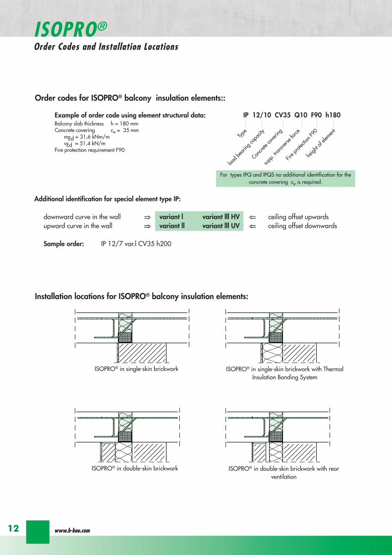

IP IPT IP IPT
IP I
PT 2nd p
ositio
nIP IPT 2nd position
IP IPT IP IPT
IP IPT IPT Corner
IPT
Cor
ner
IP
IPT
IP IPT IP orIPT 1st position
IP
IPT
2nd
posi
tion
IP orIPT 1st position
Freely-protruding balcony
Side-separated internal corner balcony Internal-corner balcony
Internal-corner balconyloggia overlying on 3 sidespartially projecting
External corner balcony
ISOPROreg - Insulation at the highest level
for superior solutions
13
ISOPROreg Type IP IPTExamples
balcony side slab side
balcony side slab side
Dimensions Type IP [length in mm]
TypeTension rod Transverse force rod Supplemental transverse force
ZL QL Q8L Q10L Q12LIP 88 560 297 497 - -IP 107 690 297 497 - -IP 108 560 337 497 617 742IP 127 690 337 497 617 742IP 128 690 337 497 617 742IP 129 690 337 497 617 742IP 1210 690 337 497 617 742
Top view
section IP
section IP - X
Expansion joint spacing for ISOPROreg Type IP can be found on page 24
Configuration of the elements
Type Length of element [mm] Tension rods Transverse force rodstandard X-variation
Compression blocks
IP 88 1000 8 Oslash 8 4 Oslash 6 8 Oslash 6 4IP 107 1000 6 Oslash 8 + 2 Oslash10 4 Oslash 6 8 Oslash 6 4IP 108 1000 10 Oslash 8 4 Oslash 8 8 Oslash 8 4IP 127 1000 9 Oslash 10 4 Oslash 8 8 Oslash 8 6IP 128 1000 10 Oslash 10 4 Oslash 8 8 Oslash 8 6IP 129 1000 11 Oslash 10 4 Oslash 8 8 Oslash 8 7IP 1210 1000 12 Oslash 10 4 Oslash 8 8 Oslash 8 8
wwwh-baucom
ISOPROreg Type IPConstruction and dimensions
14
Type certificateNr 0517
Buildings InspectorateapprovalNr Z-157-244
1000
20
20
balcony slab
balcony slab
Dimensions Type IPT [length in mm]
TypeTension rod Transverse force rod Compression rods Supplemental transverse force
ZL QL DL Q10L Q12L Q14LIPT 1211 820 382 165 472 572 662IPT 1212 820 382 165 472 572 662IPT 1412 820 382 165 472 572 662IPT 1414 960 382 200 472 572 662
Top view
section IPT
Expansion joint spacing for ISOPROreg Type IPT can be found on page 24
Configuration of the elements
Type Length of element [mm] Tension rods Transverse force rodstandard X-variation
Compression rods
IPT 1211 500 + 500 6 Oslash 10 + 4 Oslash12 4 Oslash 8 8 Oslash 8 6x2 Oslash 10 + 4x2 Oslash12IPT 1212 500 + 500 10 Oslash 12 4 Oslash 8 8 Oslash 8 10x2 Oslash 12IPT 1412 500 + 500 12 Oslash 12 4 Oslash 8 8 Oslash 8 10x2 Oslash 14IPT 1414 500 + 500 10 Oslash 14 4 Oslash 8 8 Oslash 8 10x2 Oslash 14
ISOPROreg - Insulation at the highest level
for superior solutions
15
ISOPROreg Type IPTConstruction and dimensions
section IPT - X
Type certificateNr 0518
Buildings InspectorateapprovalNr Z-157-243
Types with increased transverse-force load capacity
Type IP 88Q
IP 107Q
IP 108Q
IP 127Q
IP 128Q
Rated values for transverse-force loading vRd [kNm]
Q8 (4Oslash8) h ge 160mm 618Q10 (4Oslash10) h ge 170mm 966Q12 (4Oslash12) h ge 180mm 1391
Plate thickness [cm] with re-ference to cv [mm] Rated values for moment loading mRd [kNmm]
30 35 40 45 50 IP 88 IP 107 IP 108 IP 127 IP 128
- - - - 16 103 124 137 192 203- - - 16 - 110 132 145 204 216- - 16 - 17 116 140 154 216 229- 16 - 17 - 123 148 163 228 24216 - 17 - 18 129 156 172 240 255- 17 - 18 - 136 164 181 252 26817 - 18 - 19 142 171 189 264 281- 18 - 19 - 148 179 198 276 29418 - 19 - 20 154 187 206 289 306- 19 - 20 - 161 195 215 301 31919 - 20 - 21 167 203 223 313 332- 20 - 21 - 174 211 232 325 34520 - 21 - 22 180 219 240 337 358- 21 - 22 - 187 227 249 349 37121 - 22 - 23 193 234 257 361 384- 22 - 23 - 200 242 266 373 39722 - 23 - 24 206 250 275 386 409- 23 - 24 - 213 258 284 398 42223 - 24 - 25 219 266 292 410 435- 24 - 25 - 226 274 301 422 44824 - 25 - - 232 282 309 434 461- 25 - - - 239 289 318 446 47425 - - - - 245 297 326 458 486
Rated values for transverse-force loading vRd [kNm]h = 160 - 250 [mm] 275 275 415 415 415
Rated values for transverse-force loading vRd [kNm]
Type IP 88 IP 107 IP 108 IP 127 IP 128X plusmn275 plusmn415
Q8X + 618 - 488Q10X + 966 - 696Q12X + 1391 - 696
wwwh-baucom
ISOPROreg
Dimensioning table for concrete gege C2025
16
Types with positive and negative transverse-force capacity
IP 129Q
IP 1210Q
IPT 1211Q
IPT 1212Q
IPT1412Q
IPT1414Q
Rated values for transverse-force loading vRd [kNm]
6189661391
Rated values for moment loading mRd [kNmm]
IP 129 IP 1210 IPT1211 IPT1212 IPT1412 IPT1414
234 255 283 319 368 439249 272 301 339 391 468264 288 319 360 415 497279 304 337 380 439 526293 320 356 401 463 555308 336 374 421 486 584323 352 392 442 510 613338 369 410 462 534 642353 385 428 482 558 671367 401 446 503 582 699382 417 464 523 606 728397 433 482 544 629 757412 449 501 564 653 786427 466 519 585 677 815441 482 537 605 701 844456 498 555 625 725 873471 514 573 646 749 902486 540 591 666 773 931501 566 609 687 796 960516 573 628 707 820 988530 579 646 728 844 1017545 595 664 748 868 1046560 611 682 769 892 1075
Rated values for transverse-force loading vRd [kNm]415 415 415 415 415 415
Rated values for transverse-force loading vRd [kNm]
IP 129 IP 1210 IPT 1211 IPT 1212 IPT 1412 IPT 1414plusmn415
+ 618 - 488+ 966 - 696+ 1391 - 696
ISOPROreg - Insulation at the highest level
for superior solutions
17
ISOPROreg
Dimensioning table for concrete gege C2025
balcony slab
Section A - A
AA
a
aa
b
c
b
c
c
c
b
b
tension rod ISOPRO
compression support ISOPROtransverse force bars ISOPRO
integral suspension reinforcement upper reinforcement of steel bars or mesh
lower reinforcement of steel bars or mesh
insert stirrup Oslash 8
d
d secondary reinforcement Oslash 8
concrete concrete
100
mesh support
floor balcony
1 Lay the lower reinforcement for the floor slab2 Install ISOPROreg IP and align The direction of alignment
(arrow symbol on top of element) must be followed3 Insert the edging (in accordance with DIN 1045-1) and
the upper floor reinforcement and bind together withthe ISOPROreg tension rods The ISOPROreg tension rodsand the support reinforcement are at the same level Ifrequired the binder on the tension rod level can be cutthrough
4 Lay the lower reinforcement and the edging for thebalcony slab in accordance with DIN 1045-1
5 Lay the balcony-side distribution rods one Oslash 8 top andbottom pos with insert stirrups pos separatedfrom the insulation body by approx 50 mm
6 Insert the upper floor reinforcement and bind to-gether with the ISOPROreg tension rods The ISOPROreg
tension rods and the support reinforcement are at thesame level
7 It is necessary when concreting to fill and pack uniformlyon both sides in order to prevent movement of the ISO-PROreg elements
ISOPROreg Type IP with on-site mesh supportThe mesh support replaces the suspension reinforce-ment It should be installed at a distance of le 100 mmfrom the insulation and raised up until it is immediatelybelow the tension reinforcement The diameter of thediagonals must be at least 5 mm The transverse forcerod can be positioned above or below the mesh sup-port
Since the contact pressure will be calculated as notgreater than fcd=085 middot fck γc no gap or edge ten-sioning reinforcement is required It is only necessaryto have edging on both sides of the insulation Thisshould be dimensioned for VRd
For indirect support of the ISOPROreg elements a suspensionreinforcement which is dimensioned for VRd is also re-quired on the floor side The bending reinforcement of thejoist must be according to structural calculations howeveras a minimum one Oslash 8 top and bottom is required
wwwh-baucom18
ISOPROreg Type IPOn-site reinforcement and installation instructions
balcony slab
upper reinforcement of steel bars or mesh
lower reinforcement of steel bars or mesh
insert stirrup Oslash 8A
Aa
b
c
a
c
b
section A - A
a
c
b
transverse force bars ISOPRO compression strut ISOPRO
integral suspension reinforcement tension rod ISOPRO
d
d
b
c
concrete concrete
secondary reinforcement Oslash 8
1 Lay the lower reinforcement for the floor slab2 Install ISOPROreg IPT and align The direction of alignment (arrow symbol on top of element) must be followed3 Insert the edging (in accordance with DIN 1045-1) and the upper floor reinforcement and bind together with the
ISOPROreg tension rods The ISOPROreg tension rods and the support reinforcement are at the same level If requiredthe binder on the tension rod level can be cut through
4 Lay the lower reinforcement and the edging for the balcony slab in accordance with DIN 1045-15 Lay the balcony-side distribution rods one Oslash 8 top and bottom pos with insert stirrups pos separated from
the insulation body by approx 50 mm6 Insert the upper floor reinforcement and bind together with the ISOPROreg tension rods The ISOPROreg tension rods
and the support reinforcement are at the same level7 It is necessary when concreting to fill and pack uniformly on both sides in order to prevent movement of the ISOPROreg
elements
For indirect support of the ISOPROreg elements a suspension reinforcement which is dimensioned for VRd is also requiredon the floor side The bending reinforcement of the joist must be according to structural calculations however as a mi-nimum one Oslash 8 top and bottom is required
Since the contact pressure will be calculated as not greater than fcd=085 middot fck γc no gap or edge tensioning rein-forcement is required It is only necessary to have edging on both sides of the insulation This should be dimensionedfor VRd
ISOPROreg - Insulation at the highest level
ISOPROreg Type IPTOn-site reinforcement and installation instructions
for superior solutions
19
ISOPROreg Type IPOn-site reinforcement and installation instructions
balcony
slab
wall
balcony
h lt
80
ab
c
a
b
c
aa
a
a
b
c
b
c
a
a
bb
a
c
c
ee
d
d
b
b
upper reinforcement of steel bars or mesh
lower reinforcement of steel bars or mesh
closed stirrup
inse
rt s
tirru
p
reinforcement
upper reinforcement of steel bars or mesh
lower reinforcement of steel bars or mesh
closed stirrup
upper reinforcement of steel bars or mesh
lower reinforcement of steel bars or mesh
clos
ed s
tirru
p
insert stirrup
parallel reinforcement
ain
sert
stir
rup
b
reinforcementb
wall
balcony wall
balcony
slab
balcony
slab
ndash If the height offset is less than 80 mm a standardelement can also be used
ndash In this case a stirrup reinforcement with an upper leglength gt ls is required to deflect the tensile force onthe floor side
ndash Dimensioning the stirrup reinforcement for the can-tilever effects and transverse forces from the balcony
slabndash For connection reinforcement on the balcony side see
page 1819ndash The necessary transverse reinforcement in the overlap
area must be proved in accordance with DIN 1045-1ndash Recommended joist width at least 200 mm
Connection to a ldquomarginallyrdquo height-offset floor slab
balcony
slab
wall
balcony
h lt
80
ab
c
a
b
c
a
a
a
a
b
c
b
c
a
a
bb
a
c
c
ee
d
d
b
b
upper reinforcement of steel bars or mesh
lower reinforcement of steel bars or mesh
closed stirrup
inse
rt s
tirru
p
reinforcement
upper reinforcement of steel bars or mesh
lower reinforcement of steel bars or mesh
closed stirrup
upper reinforcement of steel bars or mesh
lower reinforcement of steel bars or mesh
clos
ed s
tirru
p
insert stirrup
parallel reinforcement
ain
sert
stir
rup
b
reinforcementb
wall
balcony wall
balcony
slab
balcony
slab
ndash The ISOPROreg tension rods comply with the necessaryoverlap length ls given in DIN 1045-1
ndash For connection reinforcement on the balcony side seepage 1819
ndash The necessary transverse reinforcement in the overlaparea must be proved in accordance with DIN 1045-1
ndash The minimum wall thickness is dependent on the type
Connection to a vertical wall ndash connection downwards
balcony
slab
wall
balcony
h lt
80
ab
c
a
b
c
a
a
a
a
b
c
b
c
a
a
bb
a
c
c
ee
d
d
b
b
upper reinforcement of steel bars or mesh
lower reinforcement of steel bars or mesh
closed stirrup
inse
rt s
tirru
p
reinforcement
upper reinforcement of steel bars or mesh
lower reinforcement of steel bars or mesh
closed stirrup
upper reinforcement of steel bars or mesh
lower reinforcement of steel bars or mesh
clos
ed s
tirru
p
insert stirrup
parallel reinforcement
ain
sert
stir
rup
b
reinforcementb
wall
balcony wall
balcony
slab
balcony
slab
ndash The ISOPROreg tension rods comply with the necessaryoverlap length ls given in DIN 1045-1
ndash For connection reinforcement on the balcony side seepage 1819
ndash The necessary transverse reinforcement in the overlaparea must be proved in accordance with DIN 1045-1
ndash The minimum wall thickness is dependent on the type
Connection to a vertical wall ndash connection upwards
wwwh-baucom20
ISOPROreg
Special types Valid for type series IP and IPT (analogously)
balcony
slab
wall
balcony
h lt
80
ab
c
a
b
c
a
a
a
a
b
c
b
c
a
a
bb
a
c
c
ee
d
d
b
b
upper reinforcement of steel bars or mesh
lower reinforcement of steel bars or mesh
closed stirrup
inse
rt s
tirru
p
reinforcement
upper reinforcement of steel bars or mesh
lower reinforcement of steel bars or mesh
closed stirrup
upper reinforcement of steel bars or mesh
lower reinforcement of steel bars or mesh
clos
ed s
tirru
p
insert stirrup
parallel reinforcement
ain
sert
stir
rup
b
reinforcementb
wall
balcony wall
balcony
slab
balcony
slab
ndash dimensioning of the stirrup reinforcement for can-tilever effect and transverse force on the balcony slab
ndash the ISOPROreg tension rods comply with the DIN 1045-1 requirement for overlap length ls
ndash for on-site reinforcement see pages 1819
ndash the required transverse reinforcement in the overlapzone must be proven in compliance with DIN 1045-1
ndash recommended step-down width at least 220 mm
Connection to a floor slab with a step-up offset
balcony
slab
wall
balcony
h lt
80
ab
c
a
b
c
a
a
a
a
b
c
b
c
a
a
bb
a
c
c
ee
d
d
b
b
upper reinforcement of steel bars or mesh
lower reinforcement of steel bars or mesh
closed stirrup
inse
rt s
tirru
p
reinforcement
upper reinforcement of steel bars or mesh
lower reinforcement of steel bars or mesh
closed stirrup
upper reinforcement of steel bars or mesh
lower reinforcement of steel bars or mesh
clos
ed s
tirru
p
insert stirrup
parallel reinforcementa
inse
rt s
tirru
p
b
reinforcementb
wall
balcony wall
balcony
slab
balcony
slab
ndash dimensioning of the stirrup reinforcement for can-tilever effect and transverse force on the balcony slab
ndash the ISOPROreg tension rods comply with the DIN 1045-1 requirement for overlap length ls
ndash for on-site reinforcement see pages 1819
ndash the required transverse reinforcement in the overlapzone must be proven in compliance with DIN 1045-1
ndash constructive angle reinforcement pos 3ndash recommended step-down width at least 220 mm
Connection to a floor slab with step-down offset
ISOPROreg - Insulation at the highest level
for superior solutions
21
ISOPROreg
Special types Valid for type series IP and IPT (analogously)
After stripping freely-protruding concrete slabs experience a lowering of the slab edge This displacement is a com-bination of the deformation of the balcony insulation elements used and the bending of the slab itself These two de-formations are superimposed and compensated by raising the formworkThe calculations shown below give the required formwork height offset at the end of the cantilever which results fromthe ISOPROreg elements at 100 loading For the total height offset the slab deformation should be added in accor-dance with DIN 1045-1 The total height offset defined in the construction plans from the structural design engineershould take into account the planned direction of the drainage when rounding off the results
wwwh-baucom22
ISOPROreg
Deflection and height offset
Element height h [mm] IP 88IP 107IP 108
IP 127IP 128IP 129
IP 1210
IPT 1211IPT 1212IPT 1412
IPT 1414Concrete covering cv
30 35 40 45 50160 051 059 092 106
160 048 056 087 100160 170 045 053 082 094
160 170 043 050 077 089160 170 180 041 047 073 084
170 180 039 045 070 080170 180 190 037 043 067 079
180 190 035 041 064 073180 190 200 034 039 061 069
190 200 033 038 059 067190 200 210 031 036 056 064
200 210 030 035 054 062200 210 220 029 034 052 059
210 220 028 033 050 057210 220 230 027 031 049 055
220 230 026 030 047 053220 230 240 026 029 046 052
230 240 025 029 044 050230 240 250 024 028 043 049
240 250 023 027 042 047240 250 023 026 040 046
250 022 025 039 045250 021 025 038 043
Offset height of the balcony slab
ISOPROreg - Insulation at the highest level
for superior solutionsISOPROreg
Deflection and height offset
Example for defining the balcony slab height offset
mEd bending moment used to determine the height offset resulting from the ISOPROreg elementThe definitive load combination is decided by the structural engineer
mRd design moment of the ISOPROreg element taken from the dimensioning table on pages 16 and 17lk Cantilever length in [m]
ExampleCantilever length lk = 180 mSlab thickness h = 180 mmIntrinsic weight (slab and covering) g = 60 kNm2
Edge load (parapet) F = 15 kNmLive load p = 40 kNm2
Concrete covering cv = 30 mm
Design calculationsmEd= (g + p) x lk2 2 + F x lk = (60 middot 135 + 40 middot 15) middot 182 2 + 15 middot 18 middot 135 = 265 kNmmvEd = (g + p) x lk + F = (60 middot 135 + 40 middot 15) middot 18 + 15 middot 135 = 274 kNm
Selected ISOPROreg IP 127 cv 30 h = 180 mm mRd = 289 kNmm vRd = 415 kNm
Selected load combination for determination of the height offset resulting from the ISOPROreg element mEd= (g + p3) middot lk22 + F middot lk= (60 middot 135 + 403 middot 15) middot 182 2 + 15 middot 18 middot 135 =200 kNmm
uuml = 041 middot (265 289) middot 180 middot 10 = 67 mm
23
uuml [mm] = value from table middot (mEdmRd) middot lk [m] middot 10
wwwh-baucom24
The external concrete components must have expansion joints at right angles to the insulation layer in order to limitthe stress caused by changes in temperature The spacing of the joints e is given in the following table
balcony
ISOPRO ISOPRO
expansion joint
balcony
e 2
e 2
ISOPRO Type IPT Corner
expansion joint
seperation ofexpansion joints e
seperation ofexpansion joints e
expansion jointExpansion joint spacing for ISOPROreg Types IP und IPT
Rod diameter [mm] le 10 12 14 16 20
Joint spacing e [m] 130 113 101 92 80
balcony
ISOPRO ISOPRO
expansion joint
balcony
e 2
e 2
ISOPRO Type IPT Corner
expansion joint
seperation ofexpansion joints e
seperation ofexpansion joints e
expansion joint
expansion joint dowellingeg HED-S + plastic sleeves
ISOPROreg
Expansion joint spacing
For corner constructions the maximum rod leg length is e2
ISOPROreg - Insulation at the highest level
for superior solutions
25
a a
b
c
b
c
sup3100
In pre-cast units
Arrange the lower reinforcement layer including themesh support as per structural design Distance to in-sulation joint le 100 mm (applies to IP only)
Install lower section The last transverse rod in themesh must be placed as close as possible to the insula-tion observing the required concrete covering
For IP the transverse force rod can be under or on topof the mesh The mesh support should be lifted until itis underneath the tension reinforcement
Concrete the slab element
Locate and fix the associated upper section andwhere required intermediate section
Type IP is supplied with suspension reinforcement asstandard
On-site
Lay the necessary on-site reinforcement on the floorside
Lay the slab element on the pre-prepared timberbeams
Lay the necessary on-site reinforcement on the bal-cony side
Attach the associated upper section and where re-quired intermediate section Bind the tension strutto the on-site reinforcement
h = 210 to 250 mm
Important note fit additional insertion stirrups Oslash 620 or stirrup meshQ188A on the balcony side
In type IP pre-cast units In type IPT pre-cast units
a a
b
c
b
c
sup3100
Type IP on-site Type IPT on-site
Important noteThe type identification for lower and upper sections must match (see also colour identification) The direction of in-stallation (on the balcony side) is mandatory
ISOPROreg
Two-part elements
wwwh-baucom26
upper section
centre section
lower section
upper section
centre section
lower section
balcony balconyslab slab
Type IP Type IPT
Construction
All ISOPROreg elements of types IP and IPT can be supplied as two-part elements
General notes
ndash The permitted resultant stresses can be found in thetables on pages 16 and 17 of this technical information
ndash Intermediate sections can be supplied for height offsetcompensation in 20 and 40 mm thicknesses
ndash Type IP If the mesh supports are placed with a spacingof le 100 mm from the insulation joint no additionalsuspension reinforcement is required Instead asuspension reinforcement dimensioned for VRd shouldbe located along the insulation joints
ndash For information regarding the required formwork height off-set and the maximum spacing of expansion joints refer topages 22 23 and 24
ndash The adhesive labels (type designation) for the upper andlower sections must be identical Follow the instructions forthe balcony side and the floor side
The following elements also have an addi-tional colour coding
ISOPROreg Type Colour code
IP 107 greenIP 127 blueIP 128 yellowIP 1210 white
The continuity of the colour coding throughthe elements ensures correct matching everytime even for short sections
ISOPROreg
Two-part elements
ISOPROreg - Insulation at the highest level
for superior solutions
27
balcony sidebalcony side
section 1st position
section 2nd position
slab balcony
1st position
2nd
posi
tion
cv
cvslab balcony
slab balcony
section 1st position
section 2nd position
1st position
2nd
posi
tion
slab balcony
IPT 127 Corner 820mmIPT 1210 Corner 960mm
IPT 127 Corner 820mmIPT 1210 Corner 960mm
IPT
127
Cor
ner
820m
mIP
T 12
10
Cor
ner
960m
mIP
T 12
7 C
orne
r82
0mm
IPT
121
0 C
orne
r96
0mm
General notes
Area of application for type IPT-Corner from slab thickness h le 180 mmOn-site reinforcement using overlap joints in accordance with DIN 1045-12001-07 Section 126Please refer to the information regarding on-site reinforcement on page 29Special elements for h = 160 mm are possibleBecause of the compression level a minimum spacing of the floor-side filigree slabs from the insulation body of185 mm is required for the ISOPROreg IPT-Corner elements
Type Length of element [m] Tension rods Compression level Transverse force rods
IPT 107-Corner 050 + 050 5 Oslash 10 + 5 Oslash 10 2 x 4 compression block 2 Oslash 10 + 2 Oslash 10
IPT 127-Corner 062 + 062 6 Oslash 12 + 6 Oslash 12 12 Oslash 14 + 12 Oslash 14 3 Oslash 10 + 3 Oslash 10
IPT 1210-Corner 062 + 062 6 Oslash 14 + 6 Oslash 14 14 Oslash 14 + 14 Oslash 14 3 Oslash 12 + 3 Oslash 12
Configuration of the elements
IPT 107-Corner
ISOPROreg Type IPT EckConstruction and dimensions
wwwh-baucom28
Plate thickness [mm] referred to cv [mm] Dimensional values for acceptable load moments MRd [kNm]
30 35 IPT 107 Corner IPT 127 Corner IPT 1210 Corner- 180 169 277 320
180 - 178 292 337- 190 186 306 354
190 - 195 320 370- 200 203 335 387
200 - 212 349 404- 210 220 363 421
210 - 229 378 437- 220 237 392 454
220 - 246 406 471- 230 254 421 487
230 - 263 435 504- 240 271 449 521
240 - 280 463 537- 250 289 478 554
250 - 297 492 571Dimensional values for acceptable transverse forces VRd [kN]
h = 180 - 250 [mm] 483 724 1043
balcony sidebalcony side
section 1st position
section 2nd position
slab balcony
1st position
2nd
posi
tion
cv
cvslab balcony
slab balcony
section 1st position
section 2nd position
1st position
2nd
posi
tion
slab balcony
IPT 127 Corner 820mmIPT 1210 Corner 960mm
IPT 127 Corner 820mmIPT 1210 Corner 960mm
IPT
127
Cor
ner
820m
mIP
T 12
10
Cor
ner
960m
mIP
T 12
7 C
orne
r82
0mm
IPT
121
0 C
orne
r96
0mm
Dimensioning table for concrete gege C2025
IPT 127-CornerIPT 1210-Corner
ISOPROreg Type IPT CornerConstruction and dimensions
ISOPROreg - Insulation at the highest level
for superior solutions
29
1st position
2nd
posi
tion
balcony slab
a
da
b b
c c
dstarter bar 1st position supplementary reinforcement
supplementary reinforcement
supp
lem
enta
ry r
einf
orce
men
t
supp
lem
enta
ry r
einf
orce
men
t
starter bar 1st position
stra
ter
bar
2nd
posi
tion
star
ter
bar
2nd
posi
tion
Type IPT 107-Corner IPT 127-Corner IPT 1210-Corner
starter bar 1st position 5 Oslash 10 6 Oslash 12 6 Oslash 14
starter bar 2nd position 5 Oslash 10 6 Oslash 12 6 Oslash 14
Supplementaryreinforcement 5 Oslash 10 6 Oslash 12 6 Oslash 14
Supplementaryreinforcement 5 Oslash 10 6 Oslash 12 6 Oslash 14
extension of the tension reinforcement internally as well as externally length = 2 x balcony cantilever length
ISOPROreg Type IPT CornerOn-site reinforcement
wwwh-baucom30
ISOPROreg - Insulation at the highest level
for superior solutions
IPQ IPQIPH
IPH
IPH
IPH
IPQS IPQSIPH IPQQS IPQQSIPH
IPQ IPQ
IPQ
IPQQ IPQQ
IPQQ IPQQIP
QS
IPQ IPQ
IPQ
Z
IPQ
S tie rod inlower position
IPQQ IPQQ
IPQ
Z
IPQ
S tie rod inlower position
propped balcony
internal-corner balcony with props
ISOPROreg
Examples of transverse force elements
propped balcony
propped balcony with selective point connection
internal-corner balcony with props
inset balcony with tieback3-sided overlying loggia with tieback
propped balcony with selective point connection
31
wwwh-baucom32
1000
1000
balcony slab balcony slab
IPQ 86 495 mmIPQ 88 495 mmIPQ 106 615 mmIPQ 126 740 mm
IPQ 86 495 mmIPQ 88 495 mmIPQ 106 615 mmIPQ 126 740 mm80
370 80 150
Calculated values for acceptable transverse forces vRd [kNm]
Element height IPQ 64 IPQ 65 IPQ 66 IPQ 68 IPQ 610
160 - 250 mm 348 435 522 695 869
Type IPQ 64 IPQ 65 IPQ 66 IPQ 68 IPQ 610Length [mm] 1000 1000 1000 1000 1000
Transverse force rods 4 Oslash 6 5 Oslash 6 6 Oslash 6 8 Oslash 6 10 Oslash 6
Compression blocks 4 4 4 4 4needed As [cmsup2] 08 10 12 16 20
Dimensioning table - Type IPQ for concrete gege C2025
Configuration of the elements Type IPQ
section
Top view
ISOPROreg Type IPQConstruction and dimensions
IPQ 64 - 610
min Element hight depentend on rod diameter Oslash 10 h ge170 Oslash 12 h ge180 Oslash 14 h ge190
ISOPROreg - Insulation at the highest level
for superior solutions
33
balcony slab
upper reinforcement of steel bars or mesh
lower reinforcement of steel bars or mesh
transverse shear force reinforcement 2 Oslash 8
insert stirrup
ls ls
a
b
c
d
d
a
c
d
b
suspension reinforcemente
ed
secondary reinforcement 2 Oslash 8
concrete concrete
The on-site suspension reinforcement pos and should be calculated for VRd (cf type test No 0519) and loca-ted next to the transverse force rods A Oslash 8 mm steel distribution rod should be installed above and below The sus-pension reinforcement can be replaced by a mesh support (see type IP page 18)DIN 1045-1 Section 1033 applies to the proof of the transverse force capacity of the slabs without shear reinforce-ment For proof of the transverse force capacity of the slabs with shear reinforcement DIN 1045-1 Section 1034 ap-plies The maximum transmissible transverse force across the joints must be limited to 03 VRdmax zu begrenzen
ISOPROreg Type IPQOn-site reinforcement
Calculated values for acceptable transverse forces vRd [kNm]
Element height IPQ 86 IPQ 88 IPQ 106 IPQ 125 IPQ 126
160 - 250 mm 927 1236 1449 1739 2089
Type IPQ 86 IPQ 88 IPQ 106 IPQ 125 IPQ 126Length [mm] 1000 1000 1000 1000 1000
Transverse force rods 6 Oslash 8 8 Oslash 8 6 Oslash 10 5 Oslash 12 6 Oslash 12
Compression blocks 4 4 4 4 4needed As [cmsup2] 21 28 33 40 48
Configuration of the elements Type IPQ
min Element hight depentend on rod diameter Oslash 10 h ge170 Oslash 12 h ge180 Oslash 14 h ge190
wwwh-baucom34
ISOPROreg Type IPQS 2Construction and dimensions
balcony slab
balcony slab
Calculated values for acceptable transverse forces VRd [kN]
Element height IPQS 62 IPQS 82 IPQS 102 IPQS 122 IPQS 142
160 - 250 mm 174 309 483 695 947
Dimensioning table - Type IPQS2 for concrete gege C2025
Type IPQS 62 IPQS 82 IPQS 102 IPQS 122 IPQS 142
Element length [mm] 300 300 300 300 300
Transverse force rods 2 Oslash 6 2 Oslash 8 2 Oslash 10 2 Oslash 12 2 Oslash 14
Compression rods 2 Oslash 10 2 Oslash 10 3 Oslash 10 4 Oslash 12 4 Oslash 14needed As [cmsup2] 040 071 111 160 218
Configuration of the elements Type IPQS2
min Element height dependent on rod diameter Oslash 10 h ge170 Oslash 12 h ge180 Oslash 14 h ge190
IPQS 82 495mmIPQS102 615mmIPQS122 740mmIPQS 142 860mm
IPQS 62
IPQS 82 495mmIPQS102 615mmIPQS122 740mmIPQS 142 860mm
ISOPROreg - Insulation at the highest level
for superior solutions
35
Calculated values for acceptable transverse forces VRd [kN]
Element height IPQS 63 IPQS 83 IPQS 103 IPQS 123 IPQS 143
160 - 250 mm 261 464 724 1043 1420
Dimensioning table - Type IPQS3 for concrete gege C2025
Type IPQS 63 IPQS 83 IPQS 103 IPQS 123 IPQS 143
Element length [mm] 400 400 400 400 400
Transverse force rods 3 Oslash 6 3 Oslash 8 3 Oslash 10 3 Oslash 12 3 Oslash 14
Compression rods 2 Oslash 10 3 Oslash 10 4 Oslash 12 5 Oslash 12 6 Oslash 14needed As [cmsup2] 060 107 167 240 327
Configuration of the elements Type IPQS3
balcony slab
balcony slab
ISOPROreg Type IPQS 3Construction and dimensionsn
IPQS 83 495mmIPQS103 615mmIPQS123 740mmIPQS 143 860mm
IPQS 63
IPQS 83 495mmIPQS103 615mmIPQS123 740mmIPQS 143 860mm
min Element height dependent on rod diameter Oslash 10 h ge170 Oslash 12 h ge180 Oslash 14 h ge190
wwwh-baucom36
ISOPROreg Type IPQQConstruction and dimensions
1000
1000
balcony balconyslab slab
180 80 150 80165 165
370 80 80150
IPQQ 86 495 mmIPQQ 106 615 mmIPQQ 126 740 mm
IPQQ 86 495 mmIPQQ 106 615 mmIPQQ 126 740 mm
IPQQ 64 IPQQ 66IPQQ 68 IPQQ 610
Calculated values for acceptable transverse forces vRd [kNm]
Element height IPQQ 64 IPQQ 66 IPQQ 68 IPQQ 610 IPQQ 86 IPQQ 106 IPQQ 126
160 - 250 mm plusmn348 plusmn522 plusmn695 plusmn869 plusmn927 plusmn1449 plusmn2086
Type IPQQ 64 IPQQ 66 IPQQ 68 IPQQ 610 IPQQ 86 IPQQ 106 IPQQ 126Element length [mm] 500 + 500 500 + 500 500 + 500 500 + 500 500 + 500 500 + 500 500 + 500Transverse force rods 2x4 Oslash 6 2x6 Oslash 6 2x8 Oslash 6 2x10 Oslash 6 2x6 Oslash 8 2x6 Oslash 10 2x6 Oslash 12
Compression rods 4 Oslash 10 4 Oslash 10 6 Oslash 10 6 Oslash 10 6 Oslash 10 10 Oslash 10 10 Oslash 12needed As [cmsup2] 080 120 160 200 213 333 480
Dimensioning table - Type IPQQ for concrete gege C2025
Configuration of the elements Typ IPQQ
Top view
Section
min Element height dependent on rod diameter Oslash 10 h ge170 Oslash 12 h ge180 Oslash 14 h ge190
ISOPROreg - Insulation at the highest level
for superior solutions
37
ISOPROreg Type IPQQOn-site reinforcement
balcony slab
upper reinforcement of steel bars or mesh
lower reinforcement of steel bars or mesh
ls ls
b
c
a
c
d
b
insert stirrupa
d
dinsert stirrupa
ad
d
secondary reinforcement 2 Oslash 8
concrete concrete
secondary reinforcement 2 Oslash 8
The on-site suspension reinforcement pos should be calculated for VRd and located next to the transverse forcerods A Oslash 8 mm steel distribution rod should be installed above and below DIN 1045-1 Section 1033 applies to the proof of the transverse force capacity of the slabs without shear reinforce-ment For proof of the transverse force capacity of the slabs with shear reinforcement DIN 1045-1 Section 1034 ap-plies The maximum transmissible transverse force across the joints must be limited to 03 VRdmax
wwwh-baucom38
ISOPROreg Type IPQQS 2Construction and dimensions
balcony slab
balcony slab
Calculated values for acceptable transverse forces VRd [kN]
Element height IPQQS 62 IPQQS 82 IPQQS 102 IPQQS 122 IPQQS 142
160 - 250 mm plusmn174 plusmn309 plusmn483 plusmn695 plusmn947
Dimensioning table - Type IPQQS2 for concrete gege C2025
Type IPQQS 62 IPQQS 82 IPQQS 102 IPQQS 122 IPQQS 142
Element length [mm] 300 300 300 300 300
Transverse force rods 2x 2 Oslash 6 2x 2 Oslash 8 2x 2 Oslash 10 2x 2 Oslash 12 2x 2 Oslash 14
Compression rods 2 Oslash 10 2 Oslash 10 3 Oslash 10 4 Oslash 12 4 Oslash 14needed As [cmsup2] 040 071 111 160 218
Configuration of the elements Type IPQQS2
IPQQS 82 495mmIPQQS 102 615mmIPQQS 122 740mmIPQQS 142 860mm
IPQQS 62
IPQQS 82 495mmIPQQS 102 615mmIPQQS 122 740mmIPQQS 142 860mm
min Element height dependent on rod diameter Oslash 10 h ge170 Oslash 12 h ge180 Oslash 14 h ge190
ISOPROreg - Insulation at the highest level
for superior solutions
39
ISOPROreg Type IPQQS 3Construction and dimensions
balcony slab
balcony slab
Calculated values for acceptable transverse forces VRd [kN]
Element height IPQQS 63 IPQQS 83 IPQQS 103 IPQQS 123 IPQQS 143
160 - 250 mm plusmn261 plusmn464 plusmn724 plusmn1043 plusmn1420
Dimensioning table - Type IPQQS3 for concrete gege C2025
Type IPQQS 63 IPQQS 83 IPQQS 103 IPQQS 123 IPQQS 143
Element length [mm] 400 400 400 400 400
Transverse force rods 2x 3 Oslash 6 2x 3 Oslash 8 2x 3 Oslash 10 2x 3 Oslash 12 2x 3 Oslash 14
Compression rods 2 Oslash 10 3 Oslash 10 4 Oslash 12 5 Oslash 12 6 Oslash 14needed As [cmsup2] 060 107 167 240 327
Configuration of the elements Type IPQQS3
min Element height dependent on rod diameter Oslash 10 h ge170 Oslash 12 h ge180 Oslash 14 h ge190 alternatively in Element length 500 mm available
IPQQS 83 495mmIPQQS 103 615mmIPQQS 123 740mmIPQQS 143 860mm
IPQQS 63
IPQQS 83 495mmIPQQS 103 615mmIPQQS 123 740mmIPQQS 143 860mm
wwwh-baucom40
ISOPROreg Type IPTDConstruction and dimensions
IPTD IPTD
inset balcony
30
balcony slab
Top view
Section
Example
Table of Dimensions ndash Type IPTD [length in mm]
TypeTension rod Transverse force rod Compression rod Supplemental transverse force
ZL QL DL Q10L Q12LIPTD 126 820 497 820 617 742IPTD 127 820 497 820 617 742IPTD 1210 820 497 820 617 742IPTD 1212 820 497 820 617 742IPTD 1410 960 497 960 617 742
ISOPROreg - Insulation at the highest level
for superior solutions
41
ISOPROreg Type IPTDOn-site reinforcement
balcony slab
upper reinforcement of steelbars or mesh
lower reinforcement of steelbars or mesh
secondary reinforcement 2 Oslash 8
secondary reinforcement 2 Oslash 8
insert stirrup
ls ls
AA
a
b
c
d
d
a
c
d
b
lower reinforcement of steelbars or meshc
upper reinforcement of steelbars or meshb
d
insert stirrupee
b
c
a
a
Section A - A
ISOPRO transverse force rods ISOPRO compression rods
ISOPRO transverse force rods ISOPRO tension rods
d
concrete concrete
The on-site suspension reinforcement pos should be calculated for VRd and located next to the transverse forcerods A Oslash 8 mm steel distribution rod should be installed above and below DIN 1045-1 Section 1033 applies to the proof of the transverse force capacity of the slabs without shear reinforce-ment For proof of the transverse force capacity of the slabs with shear reinforcement DIN 1045-1 Section 1034 ap-plies The maximum transmissible transverse force across the joints must be limited to 03 VRdmax
wwwh-baucom42
ISOPROreg Type IPTDDimensioning table for concrete gege C2025
Plate thickness [mm] withreference to cv [mm] Rated values for moment loading mRd [kNmm]
30 35 IPTD 126IPTD 126
Q10IPTD 126
Q12IPTD 127
IPTD 127Q10
IPTD 127Q12
IPTD 1210
- 160 plusmn 145 - - plusmn 182 - - plusmn 253160 - plusmn 154 - - plusmn 193 - - plusmn 269- 170 plusmn 162 plusmn 146 - plusmn 204 plusmn 187 - plusmn 284
170 - plusmn 171 plusmn 154 - plusmn 214 plusmn 197 - plusmn 299- 180 plusmn 180 plusmn 162 plusmn 145 plusmn 225 plusmn 208 plusmn 190 plusmn 314
180 - plusmn 189 plusmn 170 plusmn 152 plusmn 236 plusmn 218 plusmn 199 plusmn 330- 190 plusmn 197 plusmn 178 plusmn 159 plusmn 247 plusmn 228 plusmn 209 plusmn 345
190 - plusmn 206 plusmn 186 plusmn 166 plusmn 258 plusmn 238 plusmn 218 plusmn 360- 200 plusmn 215 plusmn 194 plusmn 173 plusmn 269 plusmn 248 plusmn 227 plusmn 375
200 - plusmn 223 plusmn 202 plusmn 180 plusmn 280 plusmn 258 plusmn 236 plusmn 391- 210 plusmn 232 plusmn 209 plusmn 187 plusmn 291 plusmn 268 plusmn 246 plusmn 406
210 - plusmn 241 plusmn 217 plusmn 194 plusmn 302 plusmn 278 plusmn 255 plusmn 421- 220 plusmn 250 plusmn 225 plusmn 201 plusmn 313 plusmn 288 plusmn 264 plusmn 437
220 - plusmn 258 plusmn 233 plusmn 208 plusmn 324 plusmn 298 plusmn 273 plusmn 452- 230 plusmn 267 plusmn 241 plusmn 215 plusmn 335 plusmn 308 plusmn 283 plusmn 467
230 - plusmn 276 plusmn 249 plusmn 222 plusmn 346 plusmn 318 plusmn 292 plusmn 482- 240 plusmn 285 plusmn 257 plusmn 229 plusmn 357 plusmn 328 plusmn 301 plusmn 498
240 - plusmn 293 plusmn 265 plusmn 236 plusmn 368 plusmn 339 plusmn 310 plusmn 513- 250 plusmn 302 plusmn 272 plusmn 243 plusmn 379 plusmn 349 plusmn 320 plusmn 528
250 - plusmn 311 plusmn 280 plusmn 250 plusmn 390 plusmn 359 plusmn 329 plusmn 543
Rated values for transverse force loading vRd [kNm]
h = 160 - 250 [mm ] plusmn 415 plusmn 762 plusmn 1098 plusmn 415 plusmn 762 plusmn 1098 plusmn 415
Type IPTD 126 IPTD 126Q10
IPTD 126Q12
IPTD 127 IPTD 127Q10
IPTD 127Q12
IPTD 1210
Element lenght [mm] 500 + 500 500 + 500 500 + 500 500 + 500 500 + 500 500 + 500 500 + 500
Tension rods 6 Oslash 12 6 Oslash 12 6 Oslash 122 Oslash 10 + 6 Oslash 12
2 Oslash 10 + 6 Oslash 12
2 Oslash 10 +6 Oslash 12
10 Oslash 12
Transverse forcerods
2x4 Oslash 8 2x4 Oslash 10 2x4 Oslash 12 2x4 Oslash 8 2x4 Oslash 10 2x4 Oslash 12 2x4 Oslash 8
Compression rods 6 Oslash 12 6 Oslash 12 6 Oslash 122 Oslash 10 + 6 Oslash 12
2 Oslash 10 +6 Oslash 12
2 Oslash 10 +6 Oslash 12
10 Oslash 12
Configuration of the elements Type IPTD
ISOPROreg - Insulation at the highest level
for superior solutions
43
ISOPROreg Type IPTDDimensioning table for concrete gege C2025
Rated values for moment loading mRd [kNmm]
IPTD 1210Q10
IPTD 1210Q12
IPTD 1212IPTD 1212
Q10IPTD 1212
Q12IPTD 1410
IPTD 1410Q10
IPTD 1410Q12
- - plusmn 307 - - plusmn 349 - -- - plusmn 326 - - plusmn 371 - -
plusmn 268 - plusmn 345 plusmn 328 - plusmn 392 plusmn 377 -plusmn 282 - plusmn 363 plusmn 346 - plusmn 414 plusmn 397 -plusmn 297 plusmn 279 plusmn 382 plusmn 364 plusmn 346 plusmn 436 plusmn 418 plusmn 401plusmn 311 plusmn 293 plusmn 400 plusmn 381 plusmn 363 plusmn- 457 plusmn 439 plusmn 421plusmn 325 plusmn 306 plusmn 419 plusmn 399 plusmn 380 plusmn 479 plusmn 459 plusmn 441plusmn 340 plusmn 320 plusmn 437 plusmn 417 plusmn 397 plusmn 500 plusmn 480 plusmn 461plusmn 354 plusmn 333 plusmn 456 plusmn 434 plusmn 414 plusmn 522 plusmn 501 plusmn 480plusmn 369 plusmn 347 plusmn 474 plusmn 452 plusmn 430 plusmn 543 plusmn 522 plusmn 500plusmn 383 plusmn 361 plusmn 493 plusmn 470 plusmn 447 plusmn 565 plusmn 542 plusmn 520plusmn 397 plusmn 374 plusmn 511 plusmn 487 plusmn 464 plusmn 587 plusmn 563 plusmn 540plusmn 412 plusmn 388 plusmn 530 plusmn 505 plusmn 481 plusmn 608 plusmn 584 plusmn 560plusmn 426 plusmn 401 plusmn 548 plusmn 523 plusmn 498 plusmn 630 plusmn 604 plusmn 580plusmn 440 plusmn 415 plusmn 567 plusmn 540 plusmn 515 plusmn 351 plusmn 625 plusmn 600plusmn 455 plusmn 428 plusmn 585 plusmn 558 plusmn 531 plusmn 673 plusmn 646 plusmn 619plusmn 469 plusmn 442 plusmn 604 plusmn 576 plusmn 548 plusmn 694 plusmn 666 plusmn 639plusmn 484 plusmn 455 plusmn 622 plusmn 593 plusmn 565 plusmn 716 plusmn 687 plusmn 659plusmn 498 plusmn 469 plusmn 641 plusmn 611 plusmn 582 plusmn 737 plusmn 708 plusmn 679plusmn 512 plusmn 483 plusmn 659 plusmn 629 plusmn 599 plusmn 759 plusmn 728 plusmn 699
Rated values for transverse force loading vRd [kNm]
plusmn 762 plusmn 1098 plusmn 415 plusmn 762 plusmn 1098 plusmn 415 plusmn 762 plusmn 1098
IPTD 1210Q10
IPTD 1210Q12
IPTD 1212 IPTD 1212Q10
IPTD 1212Q12
IPTD 1410 IPTD 1410Q10
IPTD 1410Q12
500 + 500 500 + 500 500 + 500 500 + 500 500 + 500 500 + 500 500 + 500 500 + 500
10 Oslash 12 10 Oslash 12 12 Oslash 12 12 Oslash 12 12 Oslash 12 10 Oslash 14 10 Oslash 14 10 Oslash 14
2x4 Oslash 10 2x4 Oslash 12 2x4 Oslash 8 2x4 Oslash 10 2x4 Oslash 12 2x4 Oslash 8 2x4 Oslash 10 2x4 Oslash 12
10 Oslash 12 10 Oslash 12 12 Oslash 12 12 Oslash 12 12 Oslash 12 10 Oslash 14 10 Oslash 14 10 Oslash 14
wwwh-baucom44
ISOPROreg Type IPQZConstruction and dimensions
300
40
0
300
40
0
balcony slab
balcony slab
For restraint-free support with an IPQZ element it should be opposed by an IPQS element Both elements should bereinforced by a tieback which corresponds in diameter and rod count to the IPQS and IPQZAn on-site stirrup reinforcement is required to connect IPQS to the floor
Calculated values for acceptable transverse forces VRd [kN]
Element height IPQZ 62 IPQZ 82 IPQZ 102 IPQZ 122 IPQZ 142
160 - 250 mm 174 309 483 695 947
IPQZ 63 IPQZ 83 IPQZ 103 IPQZ 123 IPQZ 143
160 - 250 mm 261 464 724 1043 1420
Dimensioning table ndash Type IPQZ for concrete ge C2025
Type IPQZ 62 IPQZ 82 IPQZ 102 IPQZ 122 IPQZ 142Element lenght [mm] 300 300 300 300 300
Transverse force rods 2 Oslash 6 2 Oslash 8 2 Oslash 10 2 Oslash 12 2 Oslash 14
Configuration of the elements
Type IPQZ 63 IPQZ 83 IPQZ 103 IPQZ 123 IPQZ 143Element length [mm] 400 400 400 400 400
Transverse force rods 3 Oslash 6 3 Oslash 8 3 Oslash 10 3 Oslash 12 3 Oslash 14
min Element height dependent on rod diameter Oslash 10 h ge170 Oslash 12 h ge180 Oslash 14 h ge190
IPQZ 82 83 495mmIPQZ102 103 615mmIPQZ122 123 740mmIPQZ 142 143 860mm
IPQZ 82 83 495mmIPQZ102 103 615mmIPQZ122 123 740mmIPQZ 142 143 860mm
IPQZ 62 63
ISOPROreg - Insulation at the highest level
for superior solutions
45
ISOPROreg Type IPQZOn-site reinforcement
Type Tieback Insert stirrup for use with
IPQZ 62 2 Oslash 6 1 Oslash 6 IPQS 62
IPQZ 82 2 Oslash 8 1 Oslash 8 IPQS 82
IPQZ 102 2 Oslash 10 1 Oslash 10 IPQS 102
IPQZ 122 2 Oslash 12 2 Oslash 8 IPQS 122
IPQZ 142 2 Oslash 14 2 Oslash 10 IPQS 142
tie roda
b
stirrup for anchering tie rodb
a
slab slabbalcony
Typ IPQZ Typ IPQS
Type Tieback Insert stirrup for use with
IPQZ 63 3 Oslash 6 2 Oslash 6 IPQS 63
IPQZ 83 3 Oslash 8 2 Oslash 8 IPQS 83
IPQZ 103 3 Oslash 10 2 Oslash 10 IPQS 103
IPQZ 123 3 Oslash 12 3 Oslash 8 IPQS 123
IPQZ 143 3 Oslash 14 3 Oslash 10 IPQS 143
wwwh-baucom46
ISOPROreg Type IPHConstruction and dimensions
The ISOPROreg elements type IPH which absorb horizontal forces must only be used with ISOPROreg cantilever slabs ortransverse force connections
The number of IPH elements to be used is defined by the structural engineer whereby the expansion joint spacing mustbe maintained
When using ISOPROreg IPH elements the force absorption of the line connection must be reduced by the ratio of thelength of the IPH elements to the total connection length as a percentage
independent of cvReinforcement Length of
element
HRd
Transverse force Horizontal Transverse force Horizontal
IPH 1 2 x 1 Oslash 8 - 100 mm plusmn 74 kN -IPH 2 - 1 Oslash 10 100 mm - plusmn181 kNIPH 3 2 x 1 Oslash 8 1 Oslash 10 100 mm plusmn 74 kN plusmn 181 kN
Dimensioning table ndash Type IPH for concrete gege C2025
balcony slab
balcony slab
balcony slab
balcony slab
balcony slab
balcony slab
100
100
100
250 80 250
250 80 250
250 80 250IPH 1 for absorption of horizontal forces parallel to the insulation joint
IPH 2 for absorption of horizontal forces perpendicular to the insulation joint
IPH 3 for absorption of horizontal forces parallel and perpendicular to the insulation joint
ISOPROreg - Insulation at the highest level
for superior solutions
47
ISOPROreg Type IPHOn-site reinforcement
The installation of the ISOPROreg IPH elements is analogous to the installation of the ISOPROreg cantilever slabs or trans-verse force connectionsThe number and positions of the elements are defined in the structural detail The elements must be fixed in their posi-tions
plate slab balcony slab
ls ls
lower reinforcement of steel bars or mesh
d
lower reinforcement of steel bars or mesh
upper reinforcement of steel bars or mesh
a
aa
dc
d
insert stirrup
a
b
c
secondary reinforcement Oslash 8
b
c c
insert stirrup
wwwh-baucom48
ISOPROreg Type IPAConstruction and calculation values
29
0204
0608
1012
1416
1820
2422
2628
0204
0608
1012
1416
1820
2224
2628
0 +10 +20 +30 +40 +50-10-20-30-40-50
dimensioning axis
MEd
VEd
NEd
380
60
gt160
sup3 16
0
130
Section
Mathematical model ndash Static system Interaction diagram
NRd [kN]
M Rd[kNm]
DimensionsLength of element 350 mmFascia thickness 160 ndash 240 mmHeight of element from 160 mmThickness of insulation element 60 mm
ReinforcementTension rods 3 Oslash 8Compression rods 3 Oslash 8Transverse force rods 2 x 2 Oslash 6
Calculated values for NRd = 0MRd 29 kNmelementVRd plusmn 127 kNelement
ISOPROreg - Insulation at the highest level
for superior solutions
49
ISOPROreg Type IPAOn-site reinforcement and installation instructions
400
100
aa
bc
b c
dd
e
f
gh
h
e
g
h
f
inse
rt s
tirru
ps
conn
ectio
n re
info
rcem
ent
conn
ectio
n re
info
rcem
ent
steel bar Oslash 8
upper slab reinforcement
insert stirrups 3 Oslash 8 150 mmsupplied
insert stirrup as constructive edging
lower slab reinforcement
34
160
56 59 60 60 59 56
34
Section Plan
Installation instructions1 Lay lower reinforcement including edging
2 Install ISOPROreg elements type IPA Spacing in accordance with static requirements
3 Install positions and and tie together
4 Lay upper floor reinforcement and tie together with the ISOPROreg reinforcement element
5 Concrete the floor slab Ensure safe positioning
6 Attach the on-site insulation between the ISOPROreg elements
7 Lay the fascia reinforcement and including edging and tie together with the ISOPROreg elements
supplied insulation
Type IPAType IPA
350e = separation of elements
gt 80
gt 16
0
Spacing of the elements Spacing of expansion joints
Expansion joint spacing e le 78 mAbove corner e2 le 35 m
The parapet must be verified as being a continuous supporte = spacing of the elements in accordance with static requirements
wwwh-baucom50
+5 +15 +25 +35-5-15-25-35
05
10
15
0
MEd
NEdVEd
MRdVRd
dimensioning axis
ISOPROreg Type IPFConstruction and calculation values
42034
0
60
100
Section
Mathematical model ndash Static system Interaction diagram
DimensionsLength of element 350 mmHeight of element from 160 mmThickness of insulation element 60 mm
ReinforcementTension rods 3 Oslash 6Compression rods 3 Oslash 6Transverse force rods 2 Oslash 6
Calculated values for NRd = 0MRd plusmn 15 kNmelementVRd + 127 kNelement
NRd [kN]
M Rd[kN
m]
VRd = 127 kN
ISOPROreg - Insulation at the highest level
for superior solutions
51
ISOPROreg Type IPFOn-site reinforcement and installation instructions
b
a insert stirrup min Oslash 6 150 mm
upper slab reinforcement
ac
b
e
d
c lower slab reinforcement
est
eel b
ar Oslash
8
d2
inse
rt s
tirru
p m
in Oslash
6
150
mm
3333
56 59 60 60 59 56
160
350
Section
Plan
Installation instructions1 Lay lower reinforcement including edging
2 Install ISOPROreg elements type IPA Spacing in accordance with static requirements
3 Install positions and and tie together
4 Lay upper floor reinforcement and tie together with the ISOPROreg reinforcement element
5 Concrete the floor slab Ensure safe positioning
6 Attach the on-site insulation between the ISOPROreg elements
7 Lay the fascia reinforcement and including edging and tie together with the ISOPROreg elements
350
60
Type IPF Type IPF
e = separation of elements
supplied insulation
parapet
Spacing of the elements
Spacing of expansion joints
Expansion joint spacing e le 78 mAbove corner e2 le 35 m
The parapet must be verified as beinga continuous support e = spacing of the elements in accor-dance with static requirements
wwwh-baucom52
ISOPROreg Type IPOConstruction and calculation values
23 lK
+PRd
+HEd
lK
sliding film
reinforcedconcrete console
soft-fibre panel
sup3 18
0
sup3 150 60
725
130 60 535
350
sliding film
reinforcedconcrete console
soft-fibre panelsup3
180
sup3 150 60
725
130 60 535
350
Section
Plan Mathematical modelStatic system
DimensionsLength of element 350 mmHeight of element from 180 mmThickness of insulation element 60 mm
ReinforcementTension rods 3 Oslash 6Compression rods 3 Oslash 8Transverse force rods 2 Oslash 10
for Hed = 0 PRd plusmn 171 kNmelement max HRd + 184 kNelement
0 2 4 6 8 10 12 14 16 20 22 Horizontal force HEd [kN]
25
15
10
5
0
P Rd[kN] concrete gege C2530
concrete gege C2025
PRd = 23
PRd = 10
HEd
= 18
4
HEd
= 23
1
ISOPROreg - Insulation at the highest level
for superior solutions
53
ISOPROreg Type IPOOn-site reinforcement and installation instructions
slab
a
a
bde
b
c
c upper reinforcement of steel bars or mesh
lower reinforcement of steel bars or mesh
insert stirrupde
long
itudi
nal r
einf
orce
men
t
clos
ed s
tirru
p
concrete
concrete
Section Installation instructions
1 Lay lower reinforcement including edging
2 Install ISOPROreg elements type IPO Spacingin accordance with static requirements
3 Lay upper floor reinforcement and tie to-gether with the ISOPROreg reinforcement ele-ment
4 Attach the on-site insulation between the ISO-PROreg elements
5 Lay the console reinforcement and andtie together with the ISOPROreg elements Thefloor edge beam must be designed as a con-tinuous support
6 As far as practical the console and the floorshould be concreted simultaneously Ensuresecure positioning
reinforced concrete joist
ISOPRO Type IPO ISOPRO Type IPO
supplied insulation
e = separation of elements350
Spacing of the elements Spacing of expansion joints
Expansion joint spacing e le 78 mAbove corner e2 le 35 m
The parapet must be verified as being a continuous support e = spacing of the elements in accordance with static requirements
wwwh-baucom54
ISOPROreg Type IPSConstruction and calculation values
80
5050
80 ZL
balcony slab plate slab
wall
console
tension rod
transverse force bars
compression strut
ZL
QL
QL
DL
80
DL
100100
BSt 500 Nr Wst Nr 14571
BSt 500 Nr Wst Nr 14571
BSt 500 S
BSt 500 S
Section
80
5050
80 ZL
balcony slab plate slab
wall
console
tension rod
transverse force bars
compression strut
ZL
QL
QL
DL
80
DL
100100
BSt 500 Nr Wst Nr 14571
BSt 500 Nr Wst Nr 14571
BSt 500 S
BSt 500 S
Dimensions - Type IPS [length in mm]
Type Tension rod Transverse forcerod
Compressionrod
ZL QL DLIPS 1 690 500 430IPS 2 820 620 500IPS 3 960 745 570IPS 4 1550 865 600
Dimensioning table for concrete gege C2025Element hight 400 mm IPS 1 IPS 2 IPS 3 IPS 4
moment MRd [kNm] 221 294 375 624
transverse forces VRd [kN] 213 333 480 653
Type IPS 1 IPS 2 IPS 3 IPS 4
Element width [mm] 220 220 220 220
Tension rods 3 Oslash 10 3 Oslash 12 3 Oslash 14 4 Oslash 14
Transverse force rods 2 Oslash 8 2 Oslash 10 2 Oslash 12 2 Oslash 14
Compression rods 3 Oslash 12 3 Oslash 14 3 Oslash 16 3 Oslash 20
Other designs and dimensions are available on requestThe bonding area I underlies the determination of the anchoring lengths However if required the reinforcement rods can also be designed for bonding area II
Configuration of the elements
ISOPROreg - Insulation at the highest level
for superior solutions
55
ISOPROreg Type IPSOn-site reinforcement and installation instructions
wall plate reinforcement to structural calculations
tension rod
transverse force bars
compression strut
a
b
c
d
d
a
b
a closed stirrup
edging
c suspension reinforcementconcrete concrete
Installation instructions
1 Lay wall plate reinforcement to meet structural requirements2 Insert ISOPROreg element type IPS and tie together with the wall
reinforcement Transverse reinforcement in overlap zone in accordance with DIN 1045-1
3 Install and tie together beam reinforcement and according to structural calculations Pos edging in accordance withDIN 1045-1 Pos installed as a closed stirrup to avoid shearing
4 When concreting make sure that both sides are uniformly filled and compacted
5 Formwork offset for the beam in accordance with structural calculations
wall plate reinforcement to structural calculations
tension rod
transverse force bars
compression strut
a
b
c
d
d
a
b
a closed stirrup
edging
c suspension reinforcementconcrete concrete
80
b b
plate slab
Type IPS
wal
l pla
te
Type IPS wal
l pla
te
balcony slab
supplied insulation
Configuration of the elements Expansion joint spacing
TypeJoint spacing [m]
e
IPS 1 113
IPS 2 101
IPS 3 92
IPS 4 80
For corner constructions the maximumrod leg length is e2
wwwh-baucom56
ISOPROreg Type IPWConstruction and calculation values
ZL ZL80
420 420
QL QL
DL DL
290290
low
er s
ectio
n12
50ce
ntre
sec
tion
uppe
r se
ctio
n25
0
h =
150
- 3
50
m
80
balcony
balcony slab
slab
exte
rnal
wal
l
inte
rnal
wal
l
horizontal transverse force bars
horizontal transverse force bars
upper section bht in mm150-250 250 80
lower section bht in mm150-250 1250 80
Section
Table of Dimensions Type IPW [length in mm]
Type
Tension rod Transverseforce rod
Compressionrod
ZL QL DLIPW 1 600 423 270IPW 2 790 563 335IPW 3 980 653 410IPW 4 1170 783 470
Element width b = 150 ndash 250 mmElement height h = 150 ndash 350 mInsulation material thickness t = 80 mm
Dimensioning table for concrete gege C2025Calculated values for acceptable moments MRdy [kNm]
Element height [m] IPW 1 IPW 2 IPW 3 IPW 415 ndash 20 537 918 1169 154420 ndash 25 737 1267 1614 2132
gt 25 937 1616 2059 2720Calculated values for acceptable transverse forces [kN]
vRdz [kN] 412 622 1066 1535vRdy [kN] plusmn137 plusmn137 plusmn137 plusmn137
Type IPW 1 IPW 2 IPW 3 IPW 4Element height [m] ge150 ge150 ge150 ge150Tension rods 4 Oslash 6 4 Oslash 8 4 Oslash 10 4 Oslash 12Transverse force rods Qz 6 Oslash 6 6 Oslash 8 6 Oslash 10 6 Oslash 12Transverse force rods Qy 2 x 2 Oslash 6 2 x 2 Oslash 6 2 x 2 Oslash 6 2 x 2 Oslash 6Compression rods 6 Oslash 8 6 Oslash 10 6 Oslash 12 6 Oslash 14
Configuration of the elements
Moment effects from wind loading are absorbed bythe stiffening effect of the balcony slab
MRdz = 0
Bonding area II underlies the determination of theoverlap lengths On request the anchoring lengthscan also be dimensioned for bonding area I Designsand dimensions deviating from the standard ele-ments are available on request
ISOPROreg - Insulation at the highest level
for superior solutions
57
ISOPROreg Type IPWOn-site reinforcement and installation instructions
MRdz
VRdz VRdy
x
z
y
MRdy
Mathematical model ndash Static system
balcony slab
balcony slab
steel
mes
h re
info
rcem
ent
a
steel
mes
h re
info
rcem
ent
b
e connection reinforcementto structural calculations
f
insert stirrupas constructive edging c
c
d steel bar min 2 Oslash 8
concrete sup3 2025
exte
rnal
wal
l
inte
rnal
wal
l
insert stirrupas constructive edging
connection reinforcementto structural calculations
a bc c
d
d
steel bar min 2 Oslash 8
steel bar min 2 Oslash 8
insert stirrupinsert stirrupsteel mesh reinforcement steel mesh reinforcement
80
wall p
late
wall p
late
balcony slab
plate slab
Type IPWsupplied insulation
Type IPW
b b
e e e
Configuration of the elements
Installation instructions
1 Position internal wall reinforcement 2 Attach the constructive edging inter-
nally (insert stirrup)3 Starting at the bottom assemble the in-
dividual ISOPROreg elements type IPWand tie together with the wall reinforce-ment
4 Erect and internally and tie to-gether
5 Position the external wall reinforce-ments and in accordancewith structural design and tie to theISOPROreg elements
6 When concreting pay particular atten-tion to the positional security of the ele-ments It is recommended to fill andcompact both wall plates at the sametime
wwwh-baucom58
ISOPROreg
Approvals and Type testing
Approvals
ISOPRO Type IP Z-157-244ISOPRO Type IPT Z-157-243
Type testing
ISOPRO Type IP Test No 0517ISOPRO Type IPT Test No 0518ISOPRO Type IPQ Test No 0519
ISOPROreg - Insulation at the highest level
for superior solutions
59
ISOPROreg
Tender
___________________________________________________________________________
Scope Application area DIN 276013 Concrete and reinforced concrete Floor constructions
Structural installations__________________________________________________________________________________
ISOPROreg supporting and thermally insulating connection elements
01 supporting the balcony slab using ISOPROreg elements from H-BAU Technik GmbH02 required for installation03 m Type IP cv = mm h = mm04 m Type IPQ cv = mm h = mm05 part Type cv = mm h = mm
Special fabrication according to the following description
06 for thermal separation of the concrete07 for the storey floors pos 08 for the roofing pos 09 for 10 and11 for the balcony slap pos 12 for the loggia slab pos 13 for the cantilever slab pos 14 for the 15 in fire protection construction class F9016 the bonding is made in the reinforcement of pos and pos 17 deliver18 deliver install and bond with the connection reinforcement19 only install and bond with the connection reinforcement delivery provided20 the installation is made in accordance with instructions from
H-BAU Technik GmbHAm Guumlterbahnhof 2079771 Klettgau-ErzingenGermanyTel +49 (0) 77 42 92 15-20Fax +49 (0) 77 42 92 15-90
21 in accordance with the detail and reinforcement drawings no 22 material 23 wages 24 unit price
25 total price
wwwh-baucom60
NOTES
ISOPROreg - Insulation at the highest level
for superior solutions
61
NOTES
wwwh-baucom
Concreting with system
ISOPROreg
KESIIRAPIDOBATreg
JSDHEDFERBOXreg
BOXFERreg
GRIPRIPreg
PENTAFLEXreg
RIPINOXreg
WARMBORDreg
SCHALBORDreg
ZEMBORDreg
SCHALL-ISO ACCESSORIES
H-BAU Technik GmbHAm Guumlterbahnhof 20D-79771 Klettgau-ErzingenTel + 49 (0) 7742 92 15-20Fax + 49 (0) 7742 92 15-90infoklettgauh-baude
Produktion Nord-OstBrandenburger StraszligeD-14641 WachowTel + 49 (0) 3 3239 775-20Fax + 49 (0) 3 3239 775-90infoberlinh-baude
Balcony insulation elementsLifting anchorsShuttering tubesPush-in pegsReinforcement connectorsReinforcement connectorsMasonry connectorsSealing technologyRustproof stainless steelStop end panelsStop end panelsStop end panelsSound insulation elementsSpacers
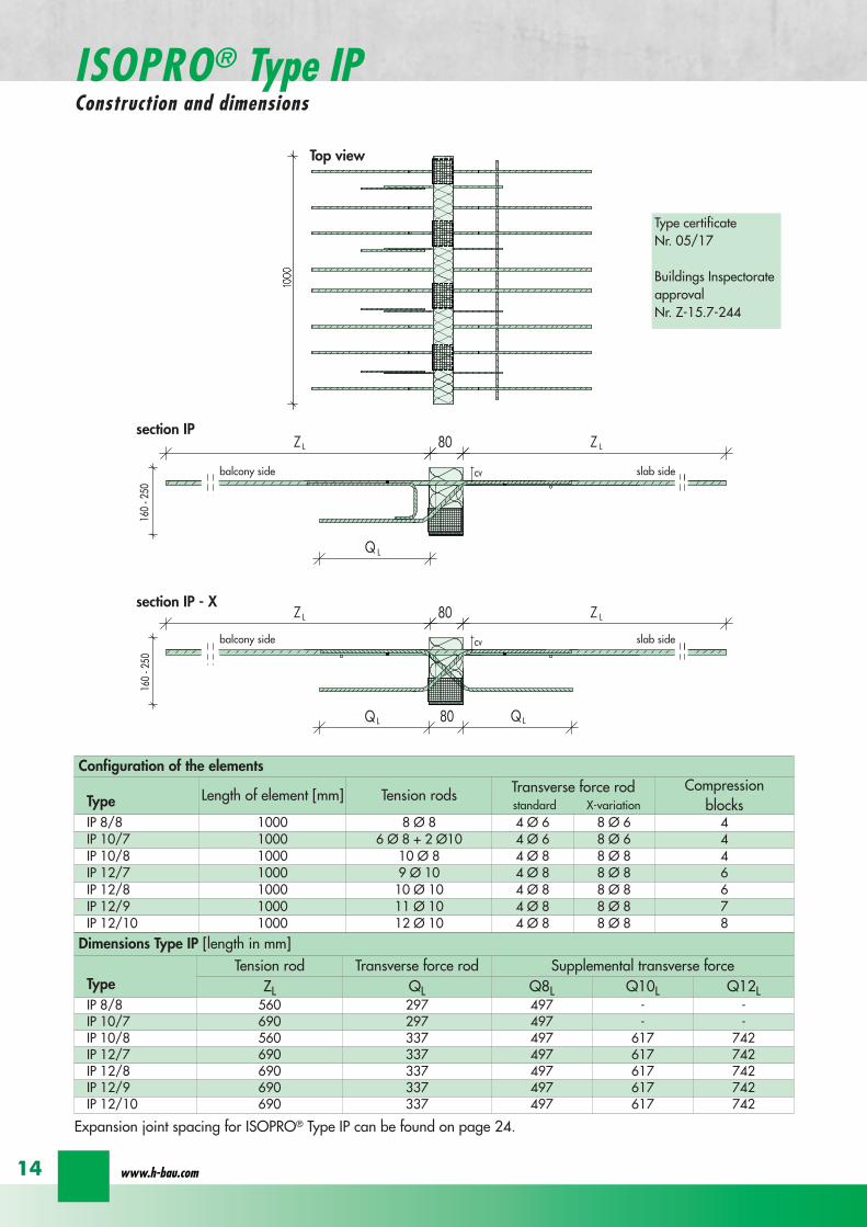
balcony side slab side
balcony side slab side
Dimensions Type IP [length in mm]
TypeTension rod Transverse force rod Supplemental transverse force
ZL QL Q8L Q10L Q12LIP 88 560 297 497 - -IP 107 690 297 497 - -IP 108 560 337 497 617 742IP 127 690 337 497 617 742IP 128 690 337 497 617 742IP 129 690 337 497 617 742IP 1210 690 337 497 617 742
Top view
section IP
section IP - X
Expansion joint spacing for ISOPROreg Type IP can be found on page 24
Configuration of the elements
Type Length of element [mm] Tension rods Transverse force rodstandard X-variation
Compression blocks
IP 88 1000 8 Oslash 8 4 Oslash 6 8 Oslash 6 4IP 107 1000 6 Oslash 8 + 2 Oslash10 4 Oslash 6 8 Oslash 6 4IP 108 1000 10 Oslash 8 4 Oslash 8 8 Oslash 8 4IP 127 1000 9 Oslash 10 4 Oslash 8 8 Oslash 8 6IP 128 1000 10 Oslash 10 4 Oslash 8 8 Oslash 8 6IP 129 1000 11 Oslash 10 4 Oslash 8 8 Oslash 8 7IP 1210 1000 12 Oslash 10 4 Oslash 8 8 Oslash 8 8
wwwh-baucom
ISOPROreg Type IPConstruction and dimensions
14
Type certificateNr 0517
Buildings InspectorateapprovalNr Z-157-244
1000
20
20
balcony slab
balcony slab
Dimensions Type IPT [length in mm]
TypeTension rod Transverse force rod Compression rods Supplemental transverse force
ZL QL DL Q10L Q12L Q14LIPT 1211 820 382 165 472 572 662IPT 1212 820 382 165 472 572 662IPT 1412 820 382 165 472 572 662IPT 1414 960 382 200 472 572 662
Top view
section IPT
Expansion joint spacing for ISOPROreg Type IPT can be found on page 24
Configuration of the elements
Type Length of element [mm] Tension rods Transverse force rodstandard X-variation
Compression rods
IPT 1211 500 + 500 6 Oslash 10 + 4 Oslash12 4 Oslash 8 8 Oslash 8 6x2 Oslash 10 + 4x2 Oslash12IPT 1212 500 + 500 10 Oslash 12 4 Oslash 8 8 Oslash 8 10x2 Oslash 12IPT 1412 500 + 500 12 Oslash 12 4 Oslash 8 8 Oslash 8 10x2 Oslash 14IPT 1414 500 + 500 10 Oslash 14 4 Oslash 8 8 Oslash 8 10x2 Oslash 14
ISOPROreg - Insulation at the highest level
for superior solutions
15
ISOPROreg Type IPTConstruction and dimensions
section IPT - X
Type certificateNr 0518
Buildings InspectorateapprovalNr Z-157-243
Types with increased transverse-force load capacity
Type IP 88Q
IP 107Q
IP 108Q
IP 127Q
IP 128Q
Rated values for transverse-force loading vRd [kNm]
Q8 (4Oslash8) h ge 160mm 618Q10 (4Oslash10) h ge 170mm 966Q12 (4Oslash12) h ge 180mm 1391
Plate thickness [cm] with re-ference to cv [mm] Rated values for moment loading mRd [kNmm]
30 35 40 45 50 IP 88 IP 107 IP 108 IP 127 IP 128
- - - - 16 103 124 137 192 203- - - 16 - 110 132 145 204 216- - 16 - 17 116 140 154 216 229- 16 - 17 - 123 148 163 228 24216 - 17 - 18 129 156 172 240 255- 17 - 18 - 136 164 181 252 26817 - 18 - 19 142 171 189 264 281- 18 - 19 - 148 179 198 276 29418 - 19 - 20 154 187 206 289 306- 19 - 20 - 161 195 215 301 31919 - 20 - 21 167 203 223 313 332- 20 - 21 - 174 211 232 325 34520 - 21 - 22 180 219 240 337 358- 21 - 22 - 187 227 249 349 37121 - 22 - 23 193 234 257 361 384- 22 - 23 - 200 242 266 373 39722 - 23 - 24 206 250 275 386 409- 23 - 24 - 213 258 284 398 42223 - 24 - 25 219 266 292 410 435- 24 - 25 - 226 274 301 422 44824 - 25 - - 232 282 309 434 461- 25 - - - 239 289 318 446 47425 - - - - 245 297 326 458 486
Rated values for transverse-force loading vRd [kNm]h = 160 - 250 [mm] 275 275 415 415 415
Rated values for transverse-force loading vRd [kNm]
Type IP 88 IP 107 IP 108 IP 127 IP 128X plusmn275 plusmn415
Q8X + 618 - 488Q10X + 966 - 696Q12X + 1391 - 696
wwwh-baucom
ISOPROreg
Dimensioning table for concrete gege C2025
16
Types with positive and negative transverse-force capacity
IP 129Q
IP 1210Q
IPT 1211Q
IPT 1212Q
IPT1412Q
IPT1414Q
Rated values for transverse-force loading vRd [kNm]
6189661391
Rated values for moment loading mRd [kNmm]
IP 129 IP 1210 IPT1211 IPT1212 IPT1412 IPT1414
234 255 283 319 368 439249 272 301 339 391 468264 288 319 360 415 497279 304 337 380 439 526293 320 356 401 463 555308 336 374 421 486 584323 352 392 442 510 613338 369 410 462 534 642353 385 428 482 558 671367 401 446 503 582 699382 417 464 523 606 728397 433 482 544 629 757412 449 501 564 653 786427 466 519 585 677 815441 482 537 605 701 844456 498 555 625 725 873471 514 573 646 749 902486 540 591 666 773 931501 566 609 687 796 960516 573 628 707 820 988530 579 646 728 844 1017545 595 664 748 868 1046560 611 682 769 892 1075
Rated values for transverse-force loading vRd [kNm]415 415 415 415 415 415
Rated values for transverse-force loading vRd [kNm]
IP 129 IP 1210 IPT 1211 IPT 1212 IPT 1412 IPT 1414plusmn415
+ 618 - 488+ 966 - 696+ 1391 - 696
ISOPROreg - Insulation at the highest level
for superior solutions
17
ISOPROreg
Dimensioning table for concrete gege C2025
balcony slab
Section A - A
AA
a
aa
b
c
b
c
c
c
b
b
tension rod ISOPRO
compression support ISOPROtransverse force bars ISOPRO
integral suspension reinforcement upper reinforcement of steel bars or mesh
lower reinforcement of steel bars or mesh
insert stirrup Oslash 8
d
d secondary reinforcement Oslash 8
concrete concrete
100
mesh support
floor balcony
1 Lay the lower reinforcement for the floor slab2 Install ISOPROreg IP and align The direction of alignment
(arrow symbol on top of element) must be followed3 Insert the edging (in accordance with DIN 1045-1) and
the upper floor reinforcement and bind together withthe ISOPROreg tension rods The ISOPROreg tension rodsand the support reinforcement are at the same level Ifrequired the binder on the tension rod level can be cutthrough
4 Lay the lower reinforcement and the edging for thebalcony slab in accordance with DIN 1045-1
5 Lay the balcony-side distribution rods one Oslash 8 top andbottom pos with insert stirrups pos separatedfrom the insulation body by approx 50 mm
6 Insert the upper floor reinforcement and bind to-gether with the ISOPROreg tension rods The ISOPROreg
tension rods and the support reinforcement are at thesame level
7 It is necessary when concreting to fill and pack uniformlyon both sides in order to prevent movement of the ISO-PROreg elements
ISOPROreg Type IP with on-site mesh supportThe mesh support replaces the suspension reinforce-ment It should be installed at a distance of le 100 mmfrom the insulation and raised up until it is immediatelybelow the tension reinforcement The diameter of thediagonals must be at least 5 mm The transverse forcerod can be positioned above or below the mesh sup-port
Since the contact pressure will be calculated as notgreater than fcd=085 middot fck γc no gap or edge ten-sioning reinforcement is required It is only necessaryto have edging on both sides of the insulation Thisshould be dimensioned for VRd
For indirect support of the ISOPROreg elements a suspensionreinforcement which is dimensioned for VRd is also re-quired on the floor side The bending reinforcement of thejoist must be according to structural calculations howeveras a minimum one Oslash 8 top and bottom is required
wwwh-baucom18
ISOPROreg Type IPOn-site reinforcement and installation instructions
balcony slab
upper reinforcement of steel bars or mesh
lower reinforcement of steel bars or mesh
insert stirrup Oslash 8A
Aa
b
c
a
c
b
section A - A
a
c
b
transverse force bars ISOPRO compression strut ISOPRO
integral suspension reinforcement tension rod ISOPRO
d
d
b
c
concrete concrete
secondary reinforcement Oslash 8
1 Lay the lower reinforcement for the floor slab2 Install ISOPROreg IPT and align The direction of alignment (arrow symbol on top of element) must be followed3 Insert the edging (in accordance with DIN 1045-1) and the upper floor reinforcement and bind together with the
ISOPROreg tension rods The ISOPROreg tension rods and the support reinforcement are at the same level If requiredthe binder on the tension rod level can be cut through
4 Lay the lower reinforcement and the edging for the balcony slab in accordance with DIN 1045-15 Lay the balcony-side distribution rods one Oslash 8 top and bottom pos with insert stirrups pos separated from
the insulation body by approx 50 mm6 Insert the upper floor reinforcement and bind together with the ISOPROreg tension rods The ISOPROreg tension rods
and the support reinforcement are at the same level7 It is necessary when concreting to fill and pack uniformly on both sides in order to prevent movement of the ISOPROreg
elements
For indirect support of the ISOPROreg elements a suspension reinforcement which is dimensioned for VRd is also requiredon the floor side The bending reinforcement of the joist must be according to structural calculations however as a mi-nimum one Oslash 8 top and bottom is required
Since the contact pressure will be calculated as not greater than fcd=085 middot fck γc no gap or edge tensioning rein-forcement is required It is only necessary to have edging on both sides of the insulation This should be dimensionedfor VRd
ISOPROreg - Insulation at the highest level
ISOPROreg Type IPTOn-site reinforcement and installation instructions
for superior solutions
19
ISOPROreg Type IPOn-site reinforcement and installation instructions
balcony
slab
wall
balcony
h lt
80
ab
c
a
b
c
aa
a
a
b
c
b
c
a
a
bb
a
c
c
ee
d
d
b
b
upper reinforcement of steel bars or mesh
lower reinforcement of steel bars or mesh
closed stirrup
inse
rt s
tirru
p
reinforcement
upper reinforcement of steel bars or mesh
lower reinforcement of steel bars or mesh
closed stirrup
upper reinforcement of steel bars or mesh
lower reinforcement of steel bars or mesh
clos
ed s
tirru
p
insert stirrup
parallel reinforcement
ain
sert
stir
rup
b
reinforcementb
wall
balcony wall
balcony
slab
balcony
slab
ndash If the height offset is less than 80 mm a standardelement can also be used
ndash In this case a stirrup reinforcement with an upper leglength gt ls is required to deflect the tensile force onthe floor side
ndash Dimensioning the stirrup reinforcement for the can-tilever effects and transverse forces from the balcony
slabndash For connection reinforcement on the balcony side see
page 1819ndash The necessary transverse reinforcement in the overlap
area must be proved in accordance with DIN 1045-1ndash Recommended joist width at least 200 mm
Connection to a ldquomarginallyrdquo height-offset floor slab
balcony
slab
wall
balcony
h lt
80
ab
c
a
b
c
a
a
a
a
b
c
b
c
a
a
bb
a
c
c
ee
d
d
b
b
upper reinforcement of steel bars or mesh
lower reinforcement of steel bars or mesh
closed stirrup
inse
rt s
tirru
p
reinforcement
upper reinforcement of steel bars or mesh
lower reinforcement of steel bars or mesh
closed stirrup
upper reinforcement of steel bars or mesh
lower reinforcement of steel bars or mesh
clos
ed s
tirru
p
insert stirrup
parallel reinforcement
ain
sert
stir
rup
b
reinforcementb
wall
balcony wall
balcony
slab
balcony
slab
ndash The ISOPROreg tension rods comply with the necessaryoverlap length ls given in DIN 1045-1
ndash For connection reinforcement on the balcony side seepage 1819
ndash The necessary transverse reinforcement in the overlaparea must be proved in accordance with DIN 1045-1
ndash The minimum wall thickness is dependent on the type
Connection to a vertical wall ndash connection downwards
balcony
slab
wall
balcony
h lt
80
ab
c
a
b
c
a
a
a
a
b
c
b
c
a
a
bb
a
c
c
ee
d
d
b
b
upper reinforcement of steel bars or mesh
lower reinforcement of steel bars or mesh
closed stirrup
inse
rt s
tirru
p
reinforcement
upper reinforcement of steel bars or mesh
lower reinforcement of steel bars or mesh
closed stirrup
upper reinforcement of steel bars or mesh
lower reinforcement of steel bars or mesh
clos
ed s
tirru
p
insert stirrup
parallel reinforcement
ain
sert
stir
rup
b
reinforcementb
wall
balcony wall
balcony
slab
balcony
slab
ndash The ISOPROreg tension rods comply with the necessaryoverlap length ls given in DIN 1045-1
ndash For connection reinforcement on the balcony side seepage 1819
ndash The necessary transverse reinforcement in the overlaparea must be proved in accordance with DIN 1045-1
ndash The minimum wall thickness is dependent on the type
Connection to a vertical wall ndash connection upwards
wwwh-baucom20
ISOPROreg
Special types Valid for type series IP and IPT (analogously)
balcony
slab
wall
balcony
h lt
80
ab
c
a
b
c
a
a
a
a
b
c
b
c
a
a
bb
a
c
c
ee
d
d
b
b
upper reinforcement of steel bars or mesh
lower reinforcement of steel bars or mesh
closed stirrup
inse
rt s
tirru
p
reinforcement
upper reinforcement of steel bars or mesh
lower reinforcement of steel bars or mesh
closed stirrup
upper reinforcement of steel bars or mesh
lower reinforcement of steel bars or mesh
clos
ed s
tirru
p
insert stirrup
parallel reinforcement
ain
sert
stir
rup
b
reinforcementb
wall
balcony wall
balcony
slab
balcony
slab
ndash dimensioning of the stirrup reinforcement for can-tilever effect and transverse force on the balcony slab
ndash the ISOPROreg tension rods comply with the DIN 1045-1 requirement for overlap length ls
ndash for on-site reinforcement see pages 1819
ndash the required transverse reinforcement in the overlapzone must be proven in compliance with DIN 1045-1
ndash recommended step-down width at least 220 mm
Connection to a floor slab with a step-up offset
balcony
slab
wall
balcony
h lt
80
ab
c
a
b
c
a
a
a
a
b
c
b
c
a
a
bb
a
c
c
ee
d
d
b
b
upper reinforcement of steel bars or mesh
lower reinforcement of steel bars or mesh
closed stirrup
inse
rt s
tirru
p
reinforcement
upper reinforcement of steel bars or mesh
lower reinforcement of steel bars or mesh
closed stirrup
upper reinforcement of steel bars or mesh
lower reinforcement of steel bars or mesh
clos
ed s
tirru
p
insert stirrup
parallel reinforcementa
inse
rt s
tirru
p
b
reinforcementb
wall
balcony wall
balcony
slab
balcony
slab
ndash dimensioning of the stirrup reinforcement for can-tilever effect and transverse force on the balcony slab
ndash the ISOPROreg tension rods comply with the DIN 1045-1 requirement for overlap length ls
ndash for on-site reinforcement see pages 1819
ndash the required transverse reinforcement in the overlapzone must be proven in compliance with DIN 1045-1
ndash constructive angle reinforcement pos 3ndash recommended step-down width at least 220 mm
Connection to a floor slab with step-down offset
ISOPROreg - Insulation at the highest level
for superior solutions
21
ISOPROreg
Special types Valid for type series IP and IPT (analogously)
After stripping freely-protruding concrete slabs experience a lowering of the slab edge This displacement is a com-bination of the deformation of the balcony insulation elements used and the bending of the slab itself These two de-formations are superimposed and compensated by raising the formworkThe calculations shown below give the required formwork height offset at the end of the cantilever which results fromthe ISOPROreg elements at 100 loading For the total height offset the slab deformation should be added in accor-dance with DIN 1045-1 The total height offset defined in the construction plans from the structural design engineershould take into account the planned direction of the drainage when rounding off the results
wwwh-baucom22
ISOPROreg
Deflection and height offset
Element height h [mm] IP 88IP 107IP 108
IP 127IP 128IP 129
IP 1210
IPT 1211IPT 1212IPT 1412
IPT 1414Concrete covering cv
30 35 40 45 50160 051 059 092 106
160 048 056 087 100160 170 045 053 082 094
160 170 043 050 077 089160 170 180 041 047 073 084
170 180 039 045 070 080170 180 190 037 043 067 079
180 190 035 041 064 073180 190 200 034 039 061 069
190 200 033 038 059 067190 200 210 031 036 056 064
200 210 030 035 054 062200 210 220 029 034 052 059
210 220 028 033 050 057210 220 230 027 031 049 055
220 230 026 030 047 053220 230 240 026 029 046 052
230 240 025 029 044 050230 240 250 024 028 043 049
240 250 023 027 042 047240 250 023 026 040 046
250 022 025 039 045250 021 025 038 043
Offset height of the balcony slab
ISOPROreg - Insulation at the highest level
for superior solutionsISOPROreg
Deflection and height offset
Example for defining the balcony slab height offset
mEd bending moment used to determine the height offset resulting from the ISOPROreg elementThe definitive load combination is decided by the structural engineer
mRd design moment of the ISOPROreg element taken from the dimensioning table on pages 16 and 17lk Cantilever length in [m]
ExampleCantilever length lk = 180 mSlab thickness h = 180 mmIntrinsic weight (slab and covering) g = 60 kNm2
Edge load (parapet) F = 15 kNmLive load p = 40 kNm2
Concrete covering cv = 30 mm
Design calculationsmEd= (g + p) x lk2 2 + F x lk = (60 middot 135 + 40 middot 15) middot 182 2 + 15 middot 18 middot 135 = 265 kNmmvEd = (g + p) x lk + F = (60 middot 135 + 40 middot 15) middot 18 + 15 middot 135 = 274 kNm
Selected ISOPROreg IP 127 cv 30 h = 180 mm mRd = 289 kNmm vRd = 415 kNm
Selected load combination for determination of the height offset resulting from the ISOPROreg element mEd= (g + p3) middot lk22 + F middot lk= (60 middot 135 + 403 middot 15) middot 182 2 + 15 middot 18 middot 135 =200 kNmm
uuml = 041 middot (265 289) middot 180 middot 10 = 67 mm
23
uuml [mm] = value from table middot (mEdmRd) middot lk [m] middot 10
wwwh-baucom24
The external concrete components must have expansion joints at right angles to the insulation layer in order to limitthe stress caused by changes in temperature The spacing of the joints e is given in the following table
balcony
ISOPRO ISOPRO
expansion joint
balcony
e 2
e 2
ISOPRO Type IPT Corner
expansion joint
seperation ofexpansion joints e
seperation ofexpansion joints e
expansion jointExpansion joint spacing for ISOPROreg Types IP und IPT
Rod diameter [mm] le 10 12 14 16 20
Joint spacing e [m] 130 113 101 92 80
balcony
ISOPRO ISOPRO
expansion joint
balcony
e 2
e 2
ISOPRO Type IPT Corner
expansion joint
seperation ofexpansion joints e
seperation ofexpansion joints e
expansion joint
expansion joint dowellingeg HED-S + plastic sleeves
ISOPROreg
Expansion joint spacing
For corner constructions the maximum rod leg length is e2
ISOPROreg - Insulation at the highest level
for superior solutions
25
a a
b
c
b
c
sup3100
In pre-cast units
Arrange the lower reinforcement layer including themesh support as per structural design Distance to in-sulation joint le 100 mm (applies to IP only)
Install lower section The last transverse rod in themesh must be placed as close as possible to the insula-tion observing the required concrete covering
For IP the transverse force rod can be under or on topof the mesh The mesh support should be lifted until itis underneath the tension reinforcement
Concrete the slab element
Locate and fix the associated upper section andwhere required intermediate section
Type IP is supplied with suspension reinforcement asstandard
On-site
Lay the necessary on-site reinforcement on the floorside
Lay the slab element on the pre-prepared timberbeams
Lay the necessary on-site reinforcement on the bal-cony side
Attach the associated upper section and where re-quired intermediate section Bind the tension strutto the on-site reinforcement
h = 210 to 250 mm
Important note fit additional insertion stirrups Oslash 620 or stirrup meshQ188A on the balcony side
In type IP pre-cast units In type IPT pre-cast units
a a
b
c
b
c
sup3100
Type IP on-site Type IPT on-site
Important noteThe type identification for lower and upper sections must match (see also colour identification) The direction of in-stallation (on the balcony side) is mandatory
ISOPROreg
Two-part elements
wwwh-baucom26
upper section
centre section
lower section
upper section
centre section
lower section
balcony balconyslab slab
Type IP Type IPT
Construction
All ISOPROreg elements of types IP and IPT can be supplied as two-part elements
General notes
ndash The permitted resultant stresses can be found in thetables on pages 16 and 17 of this technical information
ndash Intermediate sections can be supplied for height offsetcompensation in 20 and 40 mm thicknesses
ndash Type IP If the mesh supports are placed with a spacingof le 100 mm from the insulation joint no additionalsuspension reinforcement is required Instead asuspension reinforcement dimensioned for VRd shouldbe located along the insulation joints
ndash For information regarding the required formwork height off-set and the maximum spacing of expansion joints refer topages 22 23 and 24
ndash The adhesive labels (type designation) for the upper andlower sections must be identical Follow the instructions forthe balcony side and the floor side
The following elements also have an addi-tional colour coding
ISOPROreg Type Colour code
IP 107 greenIP 127 blueIP 128 yellowIP 1210 white
The continuity of the colour coding throughthe elements ensures correct matching everytime even for short sections
ISOPROreg
Two-part elements
ISOPROreg - Insulation at the highest level
for superior solutions
27
balcony sidebalcony side
section 1st position
section 2nd position
slab balcony
1st position
2nd
posi
tion
cv
cvslab balcony
slab balcony
section 1st position
section 2nd position
1st position
2nd
posi
tion
slab balcony
IPT 127 Corner 820mmIPT 1210 Corner 960mm
IPT 127 Corner 820mmIPT 1210 Corner 960mm
IPT
127
Cor
ner
820m
mIP
T 12
10
Cor
ner
960m
mIP
T 12
7 C
orne
r82
0mm
IPT
121
0 C
orne
r96
0mm
General notes
Area of application for type IPT-Corner from slab thickness h le 180 mmOn-site reinforcement using overlap joints in accordance with DIN 1045-12001-07 Section 126Please refer to the information regarding on-site reinforcement on page 29Special elements for h = 160 mm are possibleBecause of the compression level a minimum spacing of the floor-side filigree slabs from the insulation body of185 mm is required for the ISOPROreg IPT-Corner elements
Type Length of element [m] Tension rods Compression level Transverse force rods
IPT 107-Corner 050 + 050 5 Oslash 10 + 5 Oslash 10 2 x 4 compression block 2 Oslash 10 + 2 Oslash 10
IPT 127-Corner 062 + 062 6 Oslash 12 + 6 Oslash 12 12 Oslash 14 + 12 Oslash 14 3 Oslash 10 + 3 Oslash 10
IPT 1210-Corner 062 + 062 6 Oslash 14 + 6 Oslash 14 14 Oslash 14 + 14 Oslash 14 3 Oslash 12 + 3 Oslash 12
Configuration of the elements
IPT 107-Corner
ISOPROreg Type IPT EckConstruction and dimensions
wwwh-baucom28
Plate thickness [mm] referred to cv [mm] Dimensional values for acceptable load moments MRd [kNm]
30 35 IPT 107 Corner IPT 127 Corner IPT 1210 Corner- 180 169 277 320
180 - 178 292 337- 190 186 306 354
190 - 195 320 370- 200 203 335 387
200 - 212 349 404- 210 220 363 421
210 - 229 378 437- 220 237 392 454
220 - 246 406 471- 230 254 421 487
230 - 263 435 504- 240 271 449 521
240 - 280 463 537- 250 289 478 554
250 - 297 492 571Dimensional values for acceptable transverse forces VRd [kN]
h = 180 - 250 [mm] 483 724 1043
balcony sidebalcony side
section 1st position
section 2nd position
slab balcony
1st position
2nd
posi
tion
cv
cvslab balcony
slab balcony
section 1st position
section 2nd position
1st position
2nd
posi
tion
slab balcony
IPT 127 Corner 820mmIPT 1210 Corner 960mm
IPT 127 Corner 820mmIPT 1210 Corner 960mm
IPT
127
Cor
ner
820m
mIP
T 12
10
Cor
ner
960m
mIP
T 12
7 C
orne
r82
0mm
IPT
121
0 C
orne
r96
0mm
Dimensioning table for concrete gege C2025
IPT 127-CornerIPT 1210-Corner
ISOPROreg Type IPT CornerConstruction and dimensions
ISOPROreg - Insulation at the highest level
for superior solutions
29
1st position
2nd
posi
tion
balcony slab
a
da
b b
c c
dstarter bar 1st position supplementary reinforcement
supplementary reinforcement
supp
lem
enta
ry r
einf
orce
men
t
supp
lem
enta
ry r
einf
orce
men
t
starter bar 1st position
stra
ter
bar
2nd
posi
tion
star
ter
bar
2nd
posi
tion
Type IPT 107-Corner IPT 127-Corner IPT 1210-Corner
starter bar 1st position 5 Oslash 10 6 Oslash 12 6 Oslash 14
starter bar 2nd position 5 Oslash 10 6 Oslash 12 6 Oslash 14
Supplementaryreinforcement 5 Oslash 10 6 Oslash 12 6 Oslash 14
Supplementaryreinforcement 5 Oslash 10 6 Oslash 12 6 Oslash 14
extension of the tension reinforcement internally as well as externally length = 2 x balcony cantilever length
ISOPROreg Type IPT CornerOn-site reinforcement
wwwh-baucom30
ISOPROreg - Insulation at the highest level
for superior solutions
IPQ IPQIPH
IPH
IPH
IPH
IPQS IPQSIPH IPQQS IPQQSIPH
IPQ IPQ
IPQ
IPQQ IPQQ
IPQQ IPQQIP
QS
IPQ IPQ
IPQ
Z
IPQ
S tie rod inlower position
IPQQ IPQQ
IPQ
Z
IPQ
S tie rod inlower position
propped balcony
internal-corner balcony with props
ISOPROreg
Examples of transverse force elements
propped balcony
propped balcony with selective point connection
internal-corner balcony with props
inset balcony with tieback3-sided overlying loggia with tieback
propped balcony with selective point connection
31
wwwh-baucom32
1000
1000
balcony slab balcony slab
IPQ 86 495 mmIPQ 88 495 mmIPQ 106 615 mmIPQ 126 740 mm
IPQ 86 495 mmIPQ 88 495 mmIPQ 106 615 mmIPQ 126 740 mm80
370 80 150
Calculated values for acceptable transverse forces vRd [kNm]
Element height IPQ 64 IPQ 65 IPQ 66 IPQ 68 IPQ 610
160 - 250 mm 348 435 522 695 869
Type IPQ 64 IPQ 65 IPQ 66 IPQ 68 IPQ 610Length [mm] 1000 1000 1000 1000 1000
Transverse force rods 4 Oslash 6 5 Oslash 6 6 Oslash 6 8 Oslash 6 10 Oslash 6
Compression blocks 4 4 4 4 4needed As [cmsup2] 08 10 12 16 20
Dimensioning table - Type IPQ for concrete gege C2025
Configuration of the elements Type IPQ
section
Top view
ISOPROreg Type IPQConstruction and dimensions
IPQ 64 - 610
min Element hight depentend on rod diameter Oslash 10 h ge170 Oslash 12 h ge180 Oslash 14 h ge190
ISOPROreg - Insulation at the highest level
for superior solutions
33
balcony slab
upper reinforcement of steel bars or mesh
lower reinforcement of steel bars or mesh
transverse shear force reinforcement 2 Oslash 8
insert stirrup
ls ls
a
b
c
d
d
a
c
d
b
suspension reinforcemente
ed
secondary reinforcement 2 Oslash 8
concrete concrete
The on-site suspension reinforcement pos and should be calculated for VRd (cf type test No 0519) and loca-ted next to the transverse force rods A Oslash 8 mm steel distribution rod should be installed above and below The sus-pension reinforcement can be replaced by a mesh support (see type IP page 18)DIN 1045-1 Section 1033 applies to the proof of the transverse force capacity of the slabs without shear reinforce-ment For proof of the transverse force capacity of the slabs with shear reinforcement DIN 1045-1 Section 1034 ap-plies The maximum transmissible transverse force across the joints must be limited to 03 VRdmax zu begrenzen
ISOPROreg Type IPQOn-site reinforcement
Calculated values for acceptable transverse forces vRd [kNm]
Element height IPQ 86 IPQ 88 IPQ 106 IPQ 125 IPQ 126
160 - 250 mm 927 1236 1449 1739 2089
Type IPQ 86 IPQ 88 IPQ 106 IPQ 125 IPQ 126Length [mm] 1000 1000 1000 1000 1000
Transverse force rods 6 Oslash 8 8 Oslash 8 6 Oslash 10 5 Oslash 12 6 Oslash 12
Compression blocks 4 4 4 4 4needed As [cmsup2] 21 28 33 40 48
Configuration of the elements Type IPQ
min Element hight depentend on rod diameter Oslash 10 h ge170 Oslash 12 h ge180 Oslash 14 h ge190
wwwh-baucom34
ISOPROreg Type IPQS 2Construction and dimensions
balcony slab
balcony slab
Calculated values for acceptable transverse forces VRd [kN]
Element height IPQS 62 IPQS 82 IPQS 102 IPQS 122 IPQS 142
160 - 250 mm 174 309 483 695 947
Dimensioning table - Type IPQS2 for concrete gege C2025
Type IPQS 62 IPQS 82 IPQS 102 IPQS 122 IPQS 142
Element length [mm] 300 300 300 300 300
Transverse force rods 2 Oslash 6 2 Oslash 8 2 Oslash 10 2 Oslash 12 2 Oslash 14
Compression rods 2 Oslash 10 2 Oslash 10 3 Oslash 10 4 Oslash 12 4 Oslash 14needed As [cmsup2] 040 071 111 160 218
Configuration of the elements Type IPQS2
min Element height dependent on rod diameter Oslash 10 h ge170 Oslash 12 h ge180 Oslash 14 h ge190
IPQS 82 495mmIPQS102 615mmIPQS122 740mmIPQS 142 860mm
IPQS 62
IPQS 82 495mmIPQS102 615mmIPQS122 740mmIPQS 142 860mm
ISOPROreg - Insulation at the highest level
for superior solutions
35
Calculated values for acceptable transverse forces VRd [kN]
Element height IPQS 63 IPQS 83 IPQS 103 IPQS 123 IPQS 143
160 - 250 mm 261 464 724 1043 1420
Dimensioning table - Type IPQS3 for concrete gege C2025
Type IPQS 63 IPQS 83 IPQS 103 IPQS 123 IPQS 143
Element length [mm] 400 400 400 400 400
Transverse force rods 3 Oslash 6 3 Oslash 8 3 Oslash 10 3 Oslash 12 3 Oslash 14
Compression rods 2 Oslash 10 3 Oslash 10 4 Oslash 12 5 Oslash 12 6 Oslash 14needed As [cmsup2] 060 107 167 240 327
Configuration of the elements Type IPQS3
balcony slab
balcony slab
ISOPROreg Type IPQS 3Construction and dimensionsn
IPQS 83 495mmIPQS103 615mmIPQS123 740mmIPQS 143 860mm
IPQS 63
IPQS 83 495mmIPQS103 615mmIPQS123 740mmIPQS 143 860mm
min Element height dependent on rod diameter Oslash 10 h ge170 Oslash 12 h ge180 Oslash 14 h ge190
wwwh-baucom36
ISOPROreg Type IPQQConstruction and dimensions
1000
1000
balcony balconyslab slab
180 80 150 80165 165
370 80 80150
IPQQ 86 495 mmIPQQ 106 615 mmIPQQ 126 740 mm
IPQQ 86 495 mmIPQQ 106 615 mmIPQQ 126 740 mm
IPQQ 64 IPQQ 66IPQQ 68 IPQQ 610
Calculated values for acceptable transverse forces vRd [kNm]
Element height IPQQ 64 IPQQ 66 IPQQ 68 IPQQ 610 IPQQ 86 IPQQ 106 IPQQ 126
160 - 250 mm plusmn348 plusmn522 plusmn695 plusmn869 plusmn927 plusmn1449 plusmn2086
Type IPQQ 64 IPQQ 66 IPQQ 68 IPQQ 610 IPQQ 86 IPQQ 106 IPQQ 126Element length [mm] 500 + 500 500 + 500 500 + 500 500 + 500 500 + 500 500 + 500 500 + 500Transverse force rods 2x4 Oslash 6 2x6 Oslash 6 2x8 Oslash 6 2x10 Oslash 6 2x6 Oslash 8 2x6 Oslash 10 2x6 Oslash 12
Compression rods 4 Oslash 10 4 Oslash 10 6 Oslash 10 6 Oslash 10 6 Oslash 10 10 Oslash 10 10 Oslash 12needed As [cmsup2] 080 120 160 200 213 333 480
Dimensioning table - Type IPQQ for concrete gege C2025
Configuration of the elements Typ IPQQ
Top view
Section
min Element height dependent on rod diameter Oslash 10 h ge170 Oslash 12 h ge180 Oslash 14 h ge190
ISOPROreg - Insulation at the highest level
for superior solutions
37
ISOPROreg Type IPQQOn-site reinforcement
balcony slab
upper reinforcement of steel bars or mesh
lower reinforcement of steel bars or mesh
ls ls
b
c
a
c
d
b
insert stirrupa
d
dinsert stirrupa
ad
d
secondary reinforcement 2 Oslash 8
concrete concrete
secondary reinforcement 2 Oslash 8
The on-site suspension reinforcement pos should be calculated for VRd and located next to the transverse forcerods A Oslash 8 mm steel distribution rod should be installed above and below DIN 1045-1 Section 1033 applies to the proof of the transverse force capacity of the slabs without shear reinforce-ment For proof of the transverse force capacity of the slabs with shear reinforcement DIN 1045-1 Section 1034 ap-plies The maximum transmissible transverse force across the joints must be limited to 03 VRdmax
wwwh-baucom38
ISOPROreg Type IPQQS 2Construction and dimensions
balcony slab
balcony slab
Calculated values for acceptable transverse forces VRd [kN]
Element height IPQQS 62 IPQQS 82 IPQQS 102 IPQQS 122 IPQQS 142
160 - 250 mm plusmn174 plusmn309 plusmn483 plusmn695 plusmn947
Dimensioning table - Type IPQQS2 for concrete gege C2025
Type IPQQS 62 IPQQS 82 IPQQS 102 IPQQS 122 IPQQS 142
Element length [mm] 300 300 300 300 300
Transverse force rods 2x 2 Oslash 6 2x 2 Oslash 8 2x 2 Oslash 10 2x 2 Oslash 12 2x 2 Oslash 14
Compression rods 2 Oslash 10 2 Oslash 10 3 Oslash 10 4 Oslash 12 4 Oslash 14needed As [cmsup2] 040 071 111 160 218
Configuration of the elements Type IPQQS2
IPQQS 82 495mmIPQQS 102 615mmIPQQS 122 740mmIPQQS 142 860mm
IPQQS 62
IPQQS 82 495mmIPQQS 102 615mmIPQQS 122 740mmIPQQS 142 860mm
min Element height dependent on rod diameter Oslash 10 h ge170 Oslash 12 h ge180 Oslash 14 h ge190
ISOPROreg - Insulation at the highest level
for superior solutions
39
ISOPROreg Type IPQQS 3Construction and dimensions
balcony slab
balcony slab
Calculated values for acceptable transverse forces VRd [kN]
Element height IPQQS 63 IPQQS 83 IPQQS 103 IPQQS 123 IPQQS 143
160 - 250 mm plusmn261 plusmn464 plusmn724 plusmn1043 plusmn1420
Dimensioning table - Type IPQQS3 for concrete gege C2025
Type IPQQS 63 IPQQS 83 IPQQS 103 IPQQS 123 IPQQS 143
Element length [mm] 400 400 400 400 400
Transverse force rods 2x 3 Oslash 6 2x 3 Oslash 8 2x 3 Oslash 10 2x 3 Oslash 12 2x 3 Oslash 14
Compression rods 2 Oslash 10 3 Oslash 10 4 Oslash 12 5 Oslash 12 6 Oslash 14needed As [cmsup2] 060 107 167 240 327
Configuration of the elements Type IPQQS3
min Element height dependent on rod diameter Oslash 10 h ge170 Oslash 12 h ge180 Oslash 14 h ge190 alternatively in Element length 500 mm available
IPQQS 83 495mmIPQQS 103 615mmIPQQS 123 740mmIPQQS 143 860mm
IPQQS 63
IPQQS 83 495mmIPQQS 103 615mmIPQQS 123 740mmIPQQS 143 860mm
wwwh-baucom40
ISOPROreg Type IPTDConstruction and dimensions
IPTD IPTD
inset balcony
30
balcony slab
Top view
Section
Example
Table of Dimensions ndash Type IPTD [length in mm]
TypeTension rod Transverse force rod Compression rod Supplemental transverse force
ZL QL DL Q10L Q12LIPTD 126 820 497 820 617 742IPTD 127 820 497 820 617 742IPTD 1210 820 497 820 617 742IPTD 1212 820 497 820 617 742IPTD 1410 960 497 960 617 742
ISOPROreg - Insulation at the highest level
for superior solutions
41
ISOPROreg Type IPTDOn-site reinforcement
balcony slab
upper reinforcement of steelbars or mesh
lower reinforcement of steelbars or mesh
secondary reinforcement 2 Oslash 8
secondary reinforcement 2 Oslash 8
insert stirrup
ls ls
AA
a
b
c
d
d
a
c
d
b
lower reinforcement of steelbars or meshc
upper reinforcement of steelbars or meshb
d
insert stirrupee
b
c
a
a
Section A - A
ISOPRO transverse force rods ISOPRO compression rods
ISOPRO transverse force rods ISOPRO tension rods
d
concrete concrete
The on-site suspension reinforcement pos should be calculated for VRd and located next to the transverse forcerods A Oslash 8 mm steel distribution rod should be installed above and below DIN 1045-1 Section 1033 applies to the proof of the transverse force capacity of the slabs without shear reinforce-ment For proof of the transverse force capacity of the slabs with shear reinforcement DIN 1045-1 Section 1034 ap-plies The maximum transmissible transverse force across the joints must be limited to 03 VRdmax
wwwh-baucom42
ISOPROreg Type IPTDDimensioning table for concrete gege C2025
Plate thickness [mm] withreference to cv [mm] Rated values for moment loading mRd [kNmm]
30 35 IPTD 126IPTD 126
Q10IPTD 126
Q12IPTD 127
IPTD 127Q10
IPTD 127Q12
IPTD 1210
- 160 plusmn 145 - - plusmn 182 - - plusmn 253160 - plusmn 154 - - plusmn 193 - - plusmn 269- 170 plusmn 162 plusmn 146 - plusmn 204 plusmn 187 - plusmn 284
170 - plusmn 171 plusmn 154 - plusmn 214 plusmn 197 - plusmn 299- 180 plusmn 180 plusmn 162 plusmn 145 plusmn 225 plusmn 208 plusmn 190 plusmn 314
180 - plusmn 189 plusmn 170 plusmn 152 plusmn 236 plusmn 218 plusmn 199 plusmn 330- 190 plusmn 197 plusmn 178 plusmn 159 plusmn 247 plusmn 228 plusmn 209 plusmn 345
190 - plusmn 206 plusmn 186 plusmn 166 plusmn 258 plusmn 238 plusmn 218 plusmn 360- 200 plusmn 215 plusmn 194 plusmn 173 plusmn 269 plusmn 248 plusmn 227 plusmn 375
200 - plusmn 223 plusmn 202 plusmn 180 plusmn 280 plusmn 258 plusmn 236 plusmn 391- 210 plusmn 232 plusmn 209 plusmn 187 plusmn 291 plusmn 268 plusmn 246 plusmn 406
210 - plusmn 241 plusmn 217 plusmn 194 plusmn 302 plusmn 278 plusmn 255 plusmn 421- 220 plusmn 250 plusmn 225 plusmn 201 plusmn 313 plusmn 288 plusmn 264 plusmn 437
220 - plusmn 258 plusmn 233 plusmn 208 plusmn 324 plusmn 298 plusmn 273 plusmn 452- 230 plusmn 267 plusmn 241 plusmn 215 plusmn 335 plusmn 308 plusmn 283 plusmn 467
230 - plusmn 276 plusmn 249 plusmn 222 plusmn 346 plusmn 318 plusmn 292 plusmn 482- 240 plusmn 285 plusmn 257 plusmn 229 plusmn 357 plusmn 328 plusmn 301 plusmn 498
240 - plusmn 293 plusmn 265 plusmn 236 plusmn 368 plusmn 339 plusmn 310 plusmn 513- 250 plusmn 302 plusmn 272 plusmn 243 plusmn 379 plusmn 349 plusmn 320 plusmn 528
250 - plusmn 311 plusmn 280 plusmn 250 plusmn 390 plusmn 359 plusmn 329 plusmn 543
Rated values for transverse force loading vRd [kNm]
h = 160 - 250 [mm ] plusmn 415 plusmn 762 plusmn 1098 plusmn 415 plusmn 762 plusmn 1098 plusmn 415
Type IPTD 126 IPTD 126Q10
IPTD 126Q12
IPTD 127 IPTD 127Q10
IPTD 127Q12
IPTD 1210
Element lenght [mm] 500 + 500 500 + 500 500 + 500 500 + 500 500 + 500 500 + 500 500 + 500
Tension rods 6 Oslash 12 6 Oslash 12 6 Oslash 122 Oslash 10 + 6 Oslash 12
2 Oslash 10 + 6 Oslash 12
2 Oslash 10 +6 Oslash 12
10 Oslash 12
Transverse forcerods
2x4 Oslash 8 2x4 Oslash 10 2x4 Oslash 12 2x4 Oslash 8 2x4 Oslash 10 2x4 Oslash 12 2x4 Oslash 8
Compression rods 6 Oslash 12 6 Oslash 12 6 Oslash 122 Oslash 10 + 6 Oslash 12
2 Oslash 10 +6 Oslash 12
2 Oslash 10 +6 Oslash 12
10 Oslash 12
Configuration of the elements Type IPTD
ISOPROreg - Insulation at the highest level
for superior solutions
43
ISOPROreg Type IPTDDimensioning table for concrete gege C2025
Rated values for moment loading mRd [kNmm]
IPTD 1210Q10
IPTD 1210Q12
IPTD 1212IPTD 1212
Q10IPTD 1212
Q12IPTD 1410
IPTD 1410Q10
IPTD 1410Q12
- - plusmn 307 - - plusmn 349 - -- - plusmn 326 - - plusmn 371 - -
plusmn 268 - plusmn 345 plusmn 328 - plusmn 392 plusmn 377 -plusmn 282 - plusmn 363 plusmn 346 - plusmn 414 plusmn 397 -plusmn 297 plusmn 279 plusmn 382 plusmn 364 plusmn 346 plusmn 436 plusmn 418 plusmn 401plusmn 311 plusmn 293 plusmn 400 plusmn 381 plusmn 363 plusmn- 457 plusmn 439 plusmn 421plusmn 325 plusmn 306 plusmn 419 plusmn 399 plusmn 380 plusmn 479 plusmn 459 plusmn 441plusmn 340 plusmn 320 plusmn 437 plusmn 417 plusmn 397 plusmn 500 plusmn 480 plusmn 461plusmn 354 plusmn 333 plusmn 456 plusmn 434 plusmn 414 plusmn 522 plusmn 501 plusmn 480plusmn 369 plusmn 347 plusmn 474 plusmn 452 plusmn 430 plusmn 543 plusmn 522 plusmn 500plusmn 383 plusmn 361 plusmn 493 plusmn 470 plusmn 447 plusmn 565 plusmn 542 plusmn 520plusmn 397 plusmn 374 plusmn 511 plusmn 487 plusmn 464 plusmn 587 plusmn 563 plusmn 540plusmn 412 plusmn 388 plusmn 530 plusmn 505 plusmn 481 plusmn 608 plusmn 584 plusmn 560plusmn 426 plusmn 401 plusmn 548 plusmn 523 plusmn 498 plusmn 630 plusmn 604 plusmn 580plusmn 440 plusmn 415 plusmn 567 plusmn 540 plusmn 515 plusmn 351 plusmn 625 plusmn 600plusmn 455 plusmn 428 plusmn 585 plusmn 558 plusmn 531 plusmn 673 plusmn 646 plusmn 619plusmn 469 plusmn 442 plusmn 604 plusmn 576 plusmn 548 plusmn 694 plusmn 666 plusmn 639plusmn 484 plusmn 455 plusmn 622 plusmn 593 plusmn 565 plusmn 716 plusmn 687 plusmn 659plusmn 498 plusmn 469 plusmn 641 plusmn 611 plusmn 582 plusmn 737 plusmn 708 plusmn 679plusmn 512 plusmn 483 plusmn 659 plusmn 629 plusmn 599 plusmn 759 plusmn 728 plusmn 699
Rated values for transverse force loading vRd [kNm]
plusmn 762 plusmn 1098 plusmn 415 plusmn 762 plusmn 1098 plusmn 415 plusmn 762 plusmn 1098
IPTD 1210Q10
IPTD 1210Q12
IPTD 1212 IPTD 1212Q10
IPTD 1212Q12
IPTD 1410 IPTD 1410Q10
IPTD 1410Q12
500 + 500 500 + 500 500 + 500 500 + 500 500 + 500 500 + 500 500 + 500 500 + 500
10 Oslash 12 10 Oslash 12 12 Oslash 12 12 Oslash 12 12 Oslash 12 10 Oslash 14 10 Oslash 14 10 Oslash 14
2x4 Oslash 10 2x4 Oslash 12 2x4 Oslash 8 2x4 Oslash 10 2x4 Oslash 12 2x4 Oslash 8 2x4 Oslash 10 2x4 Oslash 12
10 Oslash 12 10 Oslash 12 12 Oslash 12 12 Oslash 12 12 Oslash 12 10 Oslash 14 10 Oslash 14 10 Oslash 14
wwwh-baucom44
ISOPROreg Type IPQZConstruction and dimensions
300
40
0
300
40
0
balcony slab
balcony slab
For restraint-free support with an IPQZ element it should be opposed by an IPQS element Both elements should bereinforced by a tieback which corresponds in diameter and rod count to the IPQS and IPQZAn on-site stirrup reinforcement is required to connect IPQS to the floor
Calculated values for acceptable transverse forces VRd [kN]
Element height IPQZ 62 IPQZ 82 IPQZ 102 IPQZ 122 IPQZ 142
160 - 250 mm 174 309 483 695 947
IPQZ 63 IPQZ 83 IPQZ 103 IPQZ 123 IPQZ 143
160 - 250 mm 261 464 724 1043 1420
Dimensioning table ndash Type IPQZ for concrete ge C2025
Type IPQZ 62 IPQZ 82 IPQZ 102 IPQZ 122 IPQZ 142Element lenght [mm] 300 300 300 300 300
Transverse force rods 2 Oslash 6 2 Oslash 8 2 Oslash 10 2 Oslash 12 2 Oslash 14
Configuration of the elements
Type IPQZ 63 IPQZ 83 IPQZ 103 IPQZ 123 IPQZ 143Element length [mm] 400 400 400 400 400
Transverse force rods 3 Oslash 6 3 Oslash 8 3 Oslash 10 3 Oslash 12 3 Oslash 14
min Element height dependent on rod diameter Oslash 10 h ge170 Oslash 12 h ge180 Oslash 14 h ge190
IPQZ 82 83 495mmIPQZ102 103 615mmIPQZ122 123 740mmIPQZ 142 143 860mm
IPQZ 82 83 495mmIPQZ102 103 615mmIPQZ122 123 740mmIPQZ 142 143 860mm
IPQZ 62 63
ISOPROreg - Insulation at the highest level
for superior solutions
45
ISOPROreg Type IPQZOn-site reinforcement
Type Tieback Insert stirrup for use with
IPQZ 62 2 Oslash 6 1 Oslash 6 IPQS 62
IPQZ 82 2 Oslash 8 1 Oslash 8 IPQS 82
IPQZ 102 2 Oslash 10 1 Oslash 10 IPQS 102
IPQZ 122 2 Oslash 12 2 Oslash 8 IPQS 122
IPQZ 142 2 Oslash 14 2 Oslash 10 IPQS 142
tie roda
b
stirrup for anchering tie rodb
a
slab slabbalcony
Typ IPQZ Typ IPQS
Type Tieback Insert stirrup for use with
IPQZ 63 3 Oslash 6 2 Oslash 6 IPQS 63
IPQZ 83 3 Oslash 8 2 Oslash 8 IPQS 83
IPQZ 103 3 Oslash 10 2 Oslash 10 IPQS 103
IPQZ 123 3 Oslash 12 3 Oslash 8 IPQS 123
IPQZ 143 3 Oslash 14 3 Oslash 10 IPQS 143
wwwh-baucom46
ISOPROreg Type IPHConstruction and dimensions
The ISOPROreg elements type IPH which absorb horizontal forces must only be used with ISOPROreg cantilever slabs ortransverse force connections
The number of IPH elements to be used is defined by the structural engineer whereby the expansion joint spacing mustbe maintained
When using ISOPROreg IPH elements the force absorption of the line connection must be reduced by the ratio of thelength of the IPH elements to the total connection length as a percentage
independent of cvReinforcement Length of
element
HRd
Transverse force Horizontal Transverse force Horizontal
IPH 1 2 x 1 Oslash 8 - 100 mm plusmn 74 kN -IPH 2 - 1 Oslash 10 100 mm - plusmn181 kNIPH 3 2 x 1 Oslash 8 1 Oslash 10 100 mm plusmn 74 kN plusmn 181 kN
Dimensioning table ndash Type IPH for concrete gege C2025
balcony slab
balcony slab
balcony slab
balcony slab
balcony slab
balcony slab
100
100
100
250 80 250
250 80 250
250 80 250IPH 1 for absorption of horizontal forces parallel to the insulation joint
IPH 2 for absorption of horizontal forces perpendicular to the insulation joint
IPH 3 for absorption of horizontal forces parallel and perpendicular to the insulation joint
ISOPROreg - Insulation at the highest level
for superior solutions
47
ISOPROreg Type IPHOn-site reinforcement
The installation of the ISOPROreg IPH elements is analogous to the installation of the ISOPROreg cantilever slabs or trans-verse force connectionsThe number and positions of the elements are defined in the structural detail The elements must be fixed in their posi-tions
plate slab balcony slab
ls ls
lower reinforcement of steel bars or mesh
d
lower reinforcement of steel bars or mesh
upper reinforcement of steel bars or mesh
a
aa
dc
d
insert stirrup
a
b
c
secondary reinforcement Oslash 8
b
c c
insert stirrup
wwwh-baucom48
ISOPROreg Type IPAConstruction and calculation values
29
0204
0608
1012
1416
1820
2422
2628
0204
0608
1012
1416
1820
2224
2628
0 +10 +20 +30 +40 +50-10-20-30-40-50
dimensioning axis
MEd
VEd
NEd
380
60
gt160
sup3 16
0
130
Section
Mathematical model ndash Static system Interaction diagram
NRd [kN]
M Rd[kNm]
DimensionsLength of element 350 mmFascia thickness 160 ndash 240 mmHeight of element from 160 mmThickness of insulation element 60 mm
ReinforcementTension rods 3 Oslash 8Compression rods 3 Oslash 8Transverse force rods 2 x 2 Oslash 6
Calculated values for NRd = 0MRd 29 kNmelementVRd plusmn 127 kNelement
ISOPROreg - Insulation at the highest level
for superior solutions
49
ISOPROreg Type IPAOn-site reinforcement and installation instructions
400
100
aa
bc
b c
dd
e
f
gh
h
e
g
h
f
inse
rt s
tirru
ps
conn
ectio
n re
info
rcem
ent
conn
ectio
n re
info
rcem
ent
steel bar Oslash 8
upper slab reinforcement
insert stirrups 3 Oslash 8 150 mmsupplied
insert stirrup as constructive edging
lower slab reinforcement
34
160
56 59 60 60 59 56
34
Section Plan
Installation instructions1 Lay lower reinforcement including edging
2 Install ISOPROreg elements type IPA Spacing in accordance with static requirements
3 Install positions and and tie together
4 Lay upper floor reinforcement and tie together with the ISOPROreg reinforcement element
5 Concrete the floor slab Ensure safe positioning
6 Attach the on-site insulation between the ISOPROreg elements
7 Lay the fascia reinforcement and including edging and tie together with the ISOPROreg elements
supplied insulation
Type IPAType IPA
350e = separation of elements
gt 80
gt 16
0
Spacing of the elements Spacing of expansion joints
Expansion joint spacing e le 78 mAbove corner e2 le 35 m
The parapet must be verified as being a continuous supporte = spacing of the elements in accordance with static requirements
wwwh-baucom50
+5 +15 +25 +35-5-15-25-35
05
10
15
0
MEd
NEdVEd
MRdVRd
dimensioning axis
ISOPROreg Type IPFConstruction and calculation values
42034
0
60
100
Section
Mathematical model ndash Static system Interaction diagram
DimensionsLength of element 350 mmHeight of element from 160 mmThickness of insulation element 60 mm
ReinforcementTension rods 3 Oslash 6Compression rods 3 Oslash 6Transverse force rods 2 Oslash 6
Calculated values for NRd = 0MRd plusmn 15 kNmelementVRd + 127 kNelement
NRd [kN]
M Rd[kN
m]
VRd = 127 kN
ISOPROreg - Insulation at the highest level
for superior solutions
51
ISOPROreg Type IPFOn-site reinforcement and installation instructions
b
a insert stirrup min Oslash 6 150 mm
upper slab reinforcement
ac
b
e
d
c lower slab reinforcement
est
eel b
ar Oslash
8
d2
inse
rt s
tirru
p m
in Oslash
6
150
mm
3333
56 59 60 60 59 56
160
350
Section
Plan
Installation instructions1 Lay lower reinforcement including edging
2 Install ISOPROreg elements type IPA Spacing in accordance with static requirements
3 Install positions and and tie together
4 Lay upper floor reinforcement and tie together with the ISOPROreg reinforcement element
5 Concrete the floor slab Ensure safe positioning
6 Attach the on-site insulation between the ISOPROreg elements
7 Lay the fascia reinforcement and including edging and tie together with the ISOPROreg elements
350
60
Type IPF Type IPF
e = separation of elements
supplied insulation
parapet
Spacing of the elements
Spacing of expansion joints
Expansion joint spacing e le 78 mAbove corner e2 le 35 m
The parapet must be verified as beinga continuous support e = spacing of the elements in accor-dance with static requirements
wwwh-baucom52
ISOPROreg Type IPOConstruction and calculation values
23 lK
+PRd
+HEd
lK
sliding film
reinforcedconcrete console
soft-fibre panel
sup3 18
0
sup3 150 60
725
130 60 535
350
sliding film
reinforcedconcrete console
soft-fibre panelsup3
180
sup3 150 60
725
130 60 535
350
Section
Plan Mathematical modelStatic system
DimensionsLength of element 350 mmHeight of element from 180 mmThickness of insulation element 60 mm
ReinforcementTension rods 3 Oslash 6Compression rods 3 Oslash 8Transverse force rods 2 Oslash 10
for Hed = 0 PRd plusmn 171 kNmelement max HRd + 184 kNelement
0 2 4 6 8 10 12 14 16 20 22 Horizontal force HEd [kN]
25
15
10
5
0
P Rd[kN] concrete gege C2530
concrete gege C2025
PRd = 23
PRd = 10
HEd
= 18
4
HEd
= 23
1
ISOPROreg - Insulation at the highest level
for superior solutions
53
ISOPROreg Type IPOOn-site reinforcement and installation instructions
slab
a
a
bde
b
c
c upper reinforcement of steel bars or mesh
lower reinforcement of steel bars or mesh
insert stirrupde
long
itudi
nal r
einf
orce
men
t
clos
ed s
tirru
p
concrete
concrete
Section Installation instructions
1 Lay lower reinforcement including edging
2 Install ISOPROreg elements type IPO Spacingin accordance with static requirements
3 Lay upper floor reinforcement and tie to-gether with the ISOPROreg reinforcement ele-ment
4 Attach the on-site insulation between the ISO-PROreg elements
5 Lay the console reinforcement and andtie together with the ISOPROreg elements Thefloor edge beam must be designed as a con-tinuous support
6 As far as practical the console and the floorshould be concreted simultaneously Ensuresecure positioning
reinforced concrete joist
ISOPRO Type IPO ISOPRO Type IPO
supplied insulation
e = separation of elements350
Spacing of the elements Spacing of expansion joints
Expansion joint spacing e le 78 mAbove corner e2 le 35 m
The parapet must be verified as being a continuous support e = spacing of the elements in accordance with static requirements
wwwh-baucom54
ISOPROreg Type IPSConstruction and calculation values
80
5050
80 ZL
balcony slab plate slab
wall
console
tension rod
transverse force bars
compression strut
ZL
QL
QL
DL
80
DL
100100
BSt 500 Nr Wst Nr 14571
BSt 500 Nr Wst Nr 14571
BSt 500 S
BSt 500 S
Section
80
5050
80 ZL
balcony slab plate slab
wall
console
tension rod
transverse force bars
compression strut
ZL
QL
QL
DL
80
DL
100100
BSt 500 Nr Wst Nr 14571
BSt 500 Nr Wst Nr 14571
BSt 500 S
BSt 500 S
Dimensions - Type IPS [length in mm]
Type Tension rod Transverse forcerod
Compressionrod
ZL QL DLIPS 1 690 500 430IPS 2 820 620 500IPS 3 960 745 570IPS 4 1550 865 600
Dimensioning table for concrete gege C2025Element hight 400 mm IPS 1 IPS 2 IPS 3 IPS 4
moment MRd [kNm] 221 294 375 624
transverse forces VRd [kN] 213 333 480 653
Type IPS 1 IPS 2 IPS 3 IPS 4
Element width [mm] 220 220 220 220
Tension rods 3 Oslash 10 3 Oslash 12 3 Oslash 14 4 Oslash 14
Transverse force rods 2 Oslash 8 2 Oslash 10 2 Oslash 12 2 Oslash 14
Compression rods 3 Oslash 12 3 Oslash 14 3 Oslash 16 3 Oslash 20
Other designs and dimensions are available on requestThe bonding area I underlies the determination of the anchoring lengths However if required the reinforcement rods can also be designed for bonding area II
Configuration of the elements
ISOPROreg - Insulation at the highest level
for superior solutions
55
ISOPROreg Type IPSOn-site reinforcement and installation instructions
wall plate reinforcement to structural calculations
tension rod
transverse force bars
compression strut
a
b
c
d
d
a
b
a closed stirrup
edging
c suspension reinforcementconcrete concrete
Installation instructions
1 Lay wall plate reinforcement to meet structural requirements2 Insert ISOPROreg element type IPS and tie together with the wall
reinforcement Transverse reinforcement in overlap zone in accordance with DIN 1045-1
3 Install and tie together beam reinforcement and according to structural calculations Pos edging in accordance withDIN 1045-1 Pos installed as a closed stirrup to avoid shearing
4 When concreting make sure that both sides are uniformly filled and compacted
5 Formwork offset for the beam in accordance with structural calculations
wall plate reinforcement to structural calculations
tension rod
transverse force bars
compression strut
a
b
c
d
d
a
b
a closed stirrup
edging
c suspension reinforcementconcrete concrete
80
b b
plate slab
Type IPS
wal
l pla
te
Type IPS wal
l pla
te
balcony slab
supplied insulation
Configuration of the elements Expansion joint spacing
TypeJoint spacing [m]
e
IPS 1 113
IPS 2 101
IPS 3 92
IPS 4 80
For corner constructions the maximumrod leg length is e2
wwwh-baucom56
ISOPROreg Type IPWConstruction and calculation values
ZL ZL80
420 420
QL QL
DL DL
290290
low
er s
ectio
n12
50ce
ntre
sec
tion
uppe
r se
ctio
n25
0
h =
150
- 3
50
m
80
balcony
balcony slab
slab
exte
rnal
wal
l
inte
rnal
wal
l
horizontal transverse force bars
horizontal transverse force bars
upper section bht in mm150-250 250 80
lower section bht in mm150-250 1250 80
Section
Table of Dimensions Type IPW [length in mm]
Type
Tension rod Transverseforce rod
Compressionrod
ZL QL DLIPW 1 600 423 270IPW 2 790 563 335IPW 3 980 653 410IPW 4 1170 783 470
Element width b = 150 ndash 250 mmElement height h = 150 ndash 350 mInsulation material thickness t = 80 mm
Dimensioning table for concrete gege C2025Calculated values for acceptable moments MRdy [kNm]
Element height [m] IPW 1 IPW 2 IPW 3 IPW 415 ndash 20 537 918 1169 154420 ndash 25 737 1267 1614 2132
gt 25 937 1616 2059 2720Calculated values for acceptable transverse forces [kN]
vRdz [kN] 412 622 1066 1535vRdy [kN] plusmn137 plusmn137 plusmn137 plusmn137
Type IPW 1 IPW 2 IPW 3 IPW 4Element height [m] ge150 ge150 ge150 ge150Tension rods 4 Oslash 6 4 Oslash 8 4 Oslash 10 4 Oslash 12Transverse force rods Qz 6 Oslash 6 6 Oslash 8 6 Oslash 10 6 Oslash 12Transverse force rods Qy 2 x 2 Oslash 6 2 x 2 Oslash 6 2 x 2 Oslash 6 2 x 2 Oslash 6Compression rods 6 Oslash 8 6 Oslash 10 6 Oslash 12 6 Oslash 14
Configuration of the elements
Moment effects from wind loading are absorbed bythe stiffening effect of the balcony slab
MRdz = 0
Bonding area II underlies the determination of theoverlap lengths On request the anchoring lengthscan also be dimensioned for bonding area I Designsand dimensions deviating from the standard ele-ments are available on request
ISOPROreg - Insulation at the highest level
for superior solutions
57
ISOPROreg Type IPWOn-site reinforcement and installation instructions
MRdz
VRdz VRdy
x
z
y
MRdy
Mathematical model ndash Static system
balcony slab
balcony slab
steel
mes
h re
info
rcem
ent
a
steel
mes
h re
info
rcem
ent
b
e connection reinforcementto structural calculations
f
insert stirrupas constructive edging c
c
d steel bar min 2 Oslash 8
concrete sup3 2025
exte
rnal
wal
l
inte
rnal
wal
l
insert stirrupas constructive edging
connection reinforcementto structural calculations
a bc c
d
d
steel bar min 2 Oslash 8
steel bar min 2 Oslash 8
insert stirrupinsert stirrupsteel mesh reinforcement steel mesh reinforcement
80
wall p
late
wall p
late
balcony slab
plate slab
Type IPWsupplied insulation
Type IPW
b b
e e e
Configuration of the elements
Installation instructions
1 Position internal wall reinforcement 2 Attach the constructive edging inter-
nally (insert stirrup)3 Starting at the bottom assemble the in-
dividual ISOPROreg elements type IPWand tie together with the wall reinforce-ment
4 Erect and internally and tie to-gether
5 Position the external wall reinforce-ments and in accordancewith structural design and tie to theISOPROreg elements
6 When concreting pay particular atten-tion to the positional security of the ele-ments It is recommended to fill andcompact both wall plates at the sametime
wwwh-baucom58
ISOPROreg
Approvals and Type testing
Approvals
ISOPRO Type IP Z-157-244ISOPRO Type IPT Z-157-243
Type testing
ISOPRO Type IP Test No 0517ISOPRO Type IPT Test No 0518ISOPRO Type IPQ Test No 0519
ISOPROreg - Insulation at the highest level
for superior solutions
59
ISOPROreg
Tender
___________________________________________________________________________
Scope Application area DIN 276013 Concrete and reinforced concrete Floor constructions
Structural installations__________________________________________________________________________________
ISOPROreg supporting and thermally insulating connection elements
01 supporting the balcony slab using ISOPROreg elements from H-BAU Technik GmbH02 required for installation03 m Type IP cv = mm h = mm04 m Type IPQ cv = mm h = mm05 part Type cv = mm h = mm
Special fabrication according to the following description
06 for thermal separation of the concrete07 for the storey floors pos 08 for the roofing pos 09 for 10 and11 for the balcony slap pos 12 for the loggia slab pos 13 for the cantilever slab pos 14 for the 15 in fire protection construction class F9016 the bonding is made in the reinforcement of pos and pos 17 deliver18 deliver install and bond with the connection reinforcement19 only install and bond with the connection reinforcement delivery provided20 the installation is made in accordance with instructions from
H-BAU Technik GmbHAm Guumlterbahnhof 2079771 Klettgau-ErzingenGermanyTel +49 (0) 77 42 92 15-20Fax +49 (0) 77 42 92 15-90
21 in accordance with the detail and reinforcement drawings no 22 material 23 wages 24 unit price
25 total price
wwwh-baucom60
NOTES
ISOPROreg - Insulation at the highest level
for superior solutions
61
NOTES
wwwh-baucom
Concreting with system
ISOPROreg
KESIIRAPIDOBATreg
JSDHEDFERBOXreg
BOXFERreg
GRIPRIPreg
PENTAFLEXreg
RIPINOXreg
WARMBORDreg
SCHALBORDreg
ZEMBORDreg
SCHALL-ISO ACCESSORIES
H-BAU Technik GmbHAm Guumlterbahnhof 20D-79771 Klettgau-ErzingenTel + 49 (0) 7742 92 15-20Fax + 49 (0) 7742 92 15-90infoklettgauh-baude
Produktion Nord-OstBrandenburger StraszligeD-14641 WachowTel + 49 (0) 3 3239 775-20Fax + 49 (0) 3 3239 775-90infoberlinh-baude
Balcony insulation elementsLifting anchorsShuttering tubesPush-in pegsReinforcement connectorsReinforcement connectorsMasonry connectorsSealing technologyRustproof stainless steelStop end panelsStop end panelsStop end panelsSound insulation elementsSpacers
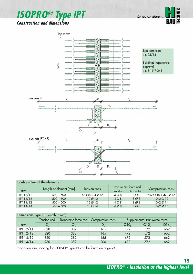
1000
20
20
balcony slab
balcony slab
Dimensions Type IPT [length in mm]
TypeTension rod Transverse force rod Compression rods Supplemental transverse force
ZL QL DL Q10L Q12L Q14LIPT 1211 820 382 165 472 572 662IPT 1212 820 382 165 472 572 662IPT 1412 820 382 165 472 572 662IPT 1414 960 382 200 472 572 662
Top view
section IPT
Expansion joint spacing for ISOPROreg Type IPT can be found on page 24
Configuration of the elements
Type Length of element [mm] Tension rods Transverse force rodstandard X-variation
Compression rods
IPT 1211 500 + 500 6 Oslash 10 + 4 Oslash12 4 Oslash 8 8 Oslash 8 6x2 Oslash 10 + 4x2 Oslash12IPT 1212 500 + 500 10 Oslash 12 4 Oslash 8 8 Oslash 8 10x2 Oslash 12IPT 1412 500 + 500 12 Oslash 12 4 Oslash 8 8 Oslash 8 10x2 Oslash 14IPT 1414 500 + 500 10 Oslash 14 4 Oslash 8 8 Oslash 8 10x2 Oslash 14
ISOPROreg - Insulation at the highest level
for superior solutions
15
ISOPROreg Type IPTConstruction and dimensions
section IPT - X
Type certificateNr 0518
Buildings InspectorateapprovalNr Z-157-243
Types with increased transverse-force load capacity
Type IP 88Q
IP 107Q
IP 108Q
IP 127Q
IP 128Q
Rated values for transverse-force loading vRd [kNm]
Q8 (4Oslash8) h ge 160mm 618Q10 (4Oslash10) h ge 170mm 966Q12 (4Oslash12) h ge 180mm 1391
Plate thickness [cm] with re-ference to cv [mm] Rated values for moment loading mRd [kNmm]
30 35 40 45 50 IP 88 IP 107 IP 108 IP 127 IP 128
- - - - 16 103 124 137 192 203- - - 16 - 110 132 145 204 216- - 16 - 17 116 140 154 216 229- 16 - 17 - 123 148 163 228 24216 - 17 - 18 129 156 172 240 255- 17 - 18 - 136 164 181 252 26817 - 18 - 19 142 171 189 264 281- 18 - 19 - 148 179 198 276 29418 - 19 - 20 154 187 206 289 306- 19 - 20 - 161 195 215 301 31919 - 20 - 21 167 203 223 313 332- 20 - 21 - 174 211 232 325 34520 - 21 - 22 180 219 240 337 358- 21 - 22 - 187 227 249 349 37121 - 22 - 23 193 234 257 361 384- 22 - 23 - 200 242 266 373 39722 - 23 - 24 206 250 275 386 409- 23 - 24 - 213 258 284 398 42223 - 24 - 25 219 266 292 410 435- 24 - 25 - 226 274 301 422 44824 - 25 - - 232 282 309 434 461- 25 - - - 239 289 318 446 47425 - - - - 245 297 326 458 486
Rated values for transverse-force loading vRd [kNm]h = 160 - 250 [mm] 275 275 415 415 415
Rated values for transverse-force loading vRd [kNm]
Type IP 88 IP 107 IP 108 IP 127 IP 128X plusmn275 plusmn415
Q8X + 618 - 488Q10X + 966 - 696Q12X + 1391 - 696
wwwh-baucom
ISOPROreg
Dimensioning table for concrete gege C2025
16
Types with positive and negative transverse-force capacity
IP 129Q
IP 1210Q
IPT 1211Q
IPT 1212Q
IPT1412Q
IPT1414Q
Rated values for transverse-force loading vRd [kNm]
6189661391
Rated values for moment loading mRd [kNmm]
IP 129 IP 1210 IPT1211 IPT1212 IPT1412 IPT1414
234 255 283 319 368 439249 272 301 339 391 468264 288 319 360 415 497279 304 337 380 439 526293 320 356 401 463 555308 336 374 421 486 584323 352 392 442 510 613338 369 410 462 534 642353 385 428 482 558 671367 401 446 503 582 699382 417 464 523 606 728397 433 482 544 629 757412 449 501 564 653 786427 466 519 585 677 815441 482 537 605 701 844456 498 555 625 725 873471 514 573 646 749 902486 540 591 666 773 931501 566 609 687 796 960516 573 628 707 820 988530 579 646 728 844 1017545 595 664 748 868 1046560 611 682 769 892 1075
Rated values for transverse-force loading vRd [kNm]415 415 415 415 415 415
Rated values for transverse-force loading vRd [kNm]
IP 129 IP 1210 IPT 1211 IPT 1212 IPT 1412 IPT 1414plusmn415
+ 618 - 488+ 966 - 696+ 1391 - 696
ISOPROreg - Insulation at the highest level
for superior solutions
17
ISOPROreg
Dimensioning table for concrete gege C2025
balcony slab
Section A - A
AA
a
aa
b
c
b
c
c
c
b
b
tension rod ISOPRO
compression support ISOPROtransverse force bars ISOPRO
integral suspension reinforcement upper reinforcement of steel bars or mesh
lower reinforcement of steel bars or mesh
insert stirrup Oslash 8
d
d secondary reinforcement Oslash 8
concrete concrete
100
mesh support
floor balcony
1 Lay the lower reinforcement for the floor slab2 Install ISOPROreg IP and align The direction of alignment
(arrow symbol on top of element) must be followed3 Insert the edging (in accordance with DIN 1045-1) and
the upper floor reinforcement and bind together withthe ISOPROreg tension rods The ISOPROreg tension rodsand the support reinforcement are at the same level Ifrequired the binder on the tension rod level can be cutthrough
4 Lay the lower reinforcement and the edging for thebalcony slab in accordance with DIN 1045-1
5 Lay the balcony-side distribution rods one Oslash 8 top andbottom pos with insert stirrups pos separatedfrom the insulation body by approx 50 mm
6 Insert the upper floor reinforcement and bind to-gether with the ISOPROreg tension rods The ISOPROreg
tension rods and the support reinforcement are at thesame level
7 It is necessary when concreting to fill and pack uniformlyon both sides in order to prevent movement of the ISO-PROreg elements
ISOPROreg Type IP with on-site mesh supportThe mesh support replaces the suspension reinforce-ment It should be installed at a distance of le 100 mmfrom the insulation and raised up until it is immediatelybelow the tension reinforcement The diameter of thediagonals must be at least 5 mm The transverse forcerod can be positioned above or below the mesh sup-port
Since the contact pressure will be calculated as notgreater than fcd=085 middot fck γc no gap or edge ten-sioning reinforcement is required It is only necessaryto have edging on both sides of the insulation Thisshould be dimensioned for VRd
For indirect support of the ISOPROreg elements a suspensionreinforcement which is dimensioned for VRd is also re-quired on the floor side The bending reinforcement of thejoist must be according to structural calculations howeveras a minimum one Oslash 8 top and bottom is required
wwwh-baucom18
ISOPROreg Type IPOn-site reinforcement and installation instructions
balcony slab
upper reinforcement of steel bars or mesh
lower reinforcement of steel bars or mesh
insert stirrup Oslash 8A
Aa
b
c
a
c
b
section A - A
a
c
b
transverse force bars ISOPRO compression strut ISOPRO
integral suspension reinforcement tension rod ISOPRO
d
d
b
c
concrete concrete
secondary reinforcement Oslash 8
1 Lay the lower reinforcement for the floor slab2 Install ISOPROreg IPT and align The direction of alignment (arrow symbol on top of element) must be followed3 Insert the edging (in accordance with DIN 1045-1) and the upper floor reinforcement and bind together with the
ISOPROreg tension rods The ISOPROreg tension rods and the support reinforcement are at the same level If requiredthe binder on the tension rod level can be cut through
4 Lay the lower reinforcement and the edging for the balcony slab in accordance with DIN 1045-15 Lay the balcony-side distribution rods one Oslash 8 top and bottom pos with insert stirrups pos separated from
the insulation body by approx 50 mm6 Insert the upper floor reinforcement and bind together with the ISOPROreg tension rods The ISOPROreg tension rods
and the support reinforcement are at the same level7 It is necessary when concreting to fill and pack uniformly on both sides in order to prevent movement of the ISOPROreg
elements
For indirect support of the ISOPROreg elements a suspension reinforcement which is dimensioned for VRd is also requiredon the floor side The bending reinforcement of the joist must be according to structural calculations however as a mi-nimum one Oslash 8 top and bottom is required
Since the contact pressure will be calculated as not greater than fcd=085 middot fck γc no gap or edge tensioning rein-forcement is required It is only necessary to have edging on both sides of the insulation This should be dimensionedfor VRd
ISOPROreg - Insulation at the highest level
ISOPROreg Type IPTOn-site reinforcement and installation instructions
for superior solutions
19
ISOPROreg Type IPOn-site reinforcement and installation instructions
balcony
slab
wall
balcony
h lt
80
ab
c
a
b
c
aa
a
a
b
c
b
c
a
a
bb
a
c
c
ee
d
d
b
b
upper reinforcement of steel bars or mesh
lower reinforcement of steel bars or mesh
closed stirrup
inse
rt s
tirru
p
reinforcement
upper reinforcement of steel bars or mesh
lower reinforcement of steel bars or mesh
closed stirrup
upper reinforcement of steel bars or mesh
lower reinforcement of steel bars or mesh
clos
ed s
tirru
p
insert stirrup
parallel reinforcement
ain
sert
stir
rup
b
reinforcementb
wall
balcony wall
balcony
slab
balcony
slab
ndash If the height offset is less than 80 mm a standardelement can also be used
ndash In this case a stirrup reinforcement with an upper leglength gt ls is required to deflect the tensile force onthe floor side
ndash Dimensioning the stirrup reinforcement for the can-tilever effects and transverse forces from the balcony
slabndash For connection reinforcement on the balcony side see
page 1819ndash The necessary transverse reinforcement in the overlap
area must be proved in accordance with DIN 1045-1ndash Recommended joist width at least 200 mm
Connection to a ldquomarginallyrdquo height-offset floor slab
balcony
slab
wall
balcony
h lt
80
ab
c
a
b
c
a
a
a
a
b
c
b
c
a
a
bb
a
c
c
ee
d
d
b
b
upper reinforcement of steel bars or mesh
lower reinforcement of steel bars or mesh
closed stirrup
inse
rt s
tirru
p
reinforcement
upper reinforcement of steel bars or mesh
lower reinforcement of steel bars or mesh
closed stirrup
upper reinforcement of steel bars or mesh
lower reinforcement of steel bars or mesh
clos
ed s
tirru
p
insert stirrup
parallel reinforcement
ain
sert
stir
rup
b
reinforcementb
wall
balcony wall
balcony
slab
balcony
slab
ndash The ISOPROreg tension rods comply with the necessaryoverlap length ls given in DIN 1045-1
ndash For connection reinforcement on the balcony side seepage 1819
ndash The necessary transverse reinforcement in the overlaparea must be proved in accordance with DIN 1045-1
ndash The minimum wall thickness is dependent on the type
Connection to a vertical wall ndash connection downwards
balcony
slab
wall
balcony
h lt
80
ab
c
a
b
c
a
a
a
a
b
c
b
c
a
a
bb
a
c
c
ee
d
d
b
b
upper reinforcement of steel bars or mesh
lower reinforcement of steel bars or mesh
closed stirrup
inse
rt s
tirru
p
reinforcement
upper reinforcement of steel bars or mesh
lower reinforcement of steel bars or mesh
closed stirrup
upper reinforcement of steel bars or mesh
lower reinforcement of steel bars or mesh
clos
ed s
tirru
p
insert stirrup
parallel reinforcement
ain
sert
stir
rup
b
reinforcementb
wall
balcony wall
balcony
slab
balcony
slab
ndash The ISOPROreg tension rods comply with the necessaryoverlap length ls given in DIN 1045-1
ndash For connection reinforcement on the balcony side seepage 1819
ndash The necessary transverse reinforcement in the overlaparea must be proved in accordance with DIN 1045-1
ndash The minimum wall thickness is dependent on the type
Connection to a vertical wall ndash connection upwards
wwwh-baucom20
ISOPROreg
Special types Valid for type series IP and IPT (analogously)
balcony
slab
wall
balcony
h lt
80
ab
c
a
b
c
a
a
a
a
b
c
b
c
a
a
bb
a
c
c
ee
d
d
b
b
upper reinforcement of steel bars or mesh
lower reinforcement of steel bars or mesh
closed stirrup
inse
rt s
tirru
p
reinforcement
upper reinforcement of steel bars or mesh
lower reinforcement of steel bars or mesh
closed stirrup
upper reinforcement of steel bars or mesh
lower reinforcement of steel bars or mesh
clos
ed s
tirru
p
insert stirrup
parallel reinforcement
ain
sert
stir
rup
b
reinforcementb
wall
balcony wall
balcony
slab
balcony
slab
ndash dimensioning of the stirrup reinforcement for can-tilever effect and transverse force on the balcony slab
ndash the ISOPROreg tension rods comply with the DIN 1045-1 requirement for overlap length ls
ndash for on-site reinforcement see pages 1819
ndash the required transverse reinforcement in the overlapzone must be proven in compliance with DIN 1045-1
ndash recommended step-down width at least 220 mm
Connection to a floor slab with a step-up offset
balcony
slab
wall
balcony
h lt
80
ab
c
a
b
c
a
a
a
a
b
c
b
c
a
a
bb
a
c
c
ee
d
d
b
b
upper reinforcement of steel bars or mesh
lower reinforcement of steel bars or mesh
closed stirrup
inse
rt s
tirru
p
reinforcement
upper reinforcement of steel bars or mesh
lower reinforcement of steel bars or mesh
closed stirrup
upper reinforcement of steel bars or mesh
lower reinforcement of steel bars or mesh
clos
ed s
tirru
p
insert stirrup
parallel reinforcementa
inse
rt s
tirru
p
b
reinforcementb
wall
balcony wall
balcony
slab
balcony
slab
ndash dimensioning of the stirrup reinforcement for can-tilever effect and transverse force on the balcony slab
ndash the ISOPROreg tension rods comply with the DIN 1045-1 requirement for overlap length ls
ndash for on-site reinforcement see pages 1819
ndash the required transverse reinforcement in the overlapzone must be proven in compliance with DIN 1045-1
ndash constructive angle reinforcement pos 3ndash recommended step-down width at least 220 mm
Connection to a floor slab with step-down offset
ISOPROreg - Insulation at the highest level
for superior solutions
21
ISOPROreg
Special types Valid for type series IP and IPT (analogously)
After stripping freely-protruding concrete slabs experience a lowering of the slab edge This displacement is a com-bination of the deformation of the balcony insulation elements used and the bending of the slab itself These two de-formations are superimposed and compensated by raising the formworkThe calculations shown below give the required formwork height offset at the end of the cantilever which results fromthe ISOPROreg elements at 100 loading For the total height offset the slab deformation should be added in accor-dance with DIN 1045-1 The total height offset defined in the construction plans from the structural design engineershould take into account the planned direction of the drainage when rounding off the results
wwwh-baucom22
ISOPROreg
Deflection and height offset
Element height h [mm] IP 88IP 107IP 108
IP 127IP 128IP 129
IP 1210
IPT 1211IPT 1212IPT 1412
IPT 1414Concrete covering cv
30 35 40 45 50160 051 059 092 106
160 048 056 087 100160 170 045 053 082 094
160 170 043 050 077 089160 170 180 041 047 073 084
170 180 039 045 070 080170 180 190 037 043 067 079
180 190 035 041 064 073180 190 200 034 039 061 069
190 200 033 038 059 067190 200 210 031 036 056 064
200 210 030 035 054 062200 210 220 029 034 052 059
210 220 028 033 050 057210 220 230 027 031 049 055
220 230 026 030 047 053220 230 240 026 029 046 052
230 240 025 029 044 050230 240 250 024 028 043 049
240 250 023 027 042 047240 250 023 026 040 046
250 022 025 039 045250 021 025 038 043
Offset height of the balcony slab
ISOPROreg - Insulation at the highest level
for superior solutionsISOPROreg
Deflection and height offset
Example for defining the balcony slab height offset
mEd bending moment used to determine the height offset resulting from the ISOPROreg elementThe definitive load combination is decided by the structural engineer
mRd design moment of the ISOPROreg element taken from the dimensioning table on pages 16 and 17lk Cantilever length in [m]
ExampleCantilever length lk = 180 mSlab thickness h = 180 mmIntrinsic weight (slab and covering) g = 60 kNm2
Edge load (parapet) F = 15 kNmLive load p = 40 kNm2
Concrete covering cv = 30 mm
Design calculationsmEd= (g + p) x lk2 2 + F x lk = (60 middot 135 + 40 middot 15) middot 182 2 + 15 middot 18 middot 135 = 265 kNmmvEd = (g + p) x lk + F = (60 middot 135 + 40 middot 15) middot 18 + 15 middot 135 = 274 kNm
Selected ISOPROreg IP 127 cv 30 h = 180 mm mRd = 289 kNmm vRd = 415 kNm
Selected load combination for determination of the height offset resulting from the ISOPROreg element mEd= (g + p3) middot lk22 + F middot lk= (60 middot 135 + 403 middot 15) middot 182 2 + 15 middot 18 middot 135 =200 kNmm
uuml = 041 middot (265 289) middot 180 middot 10 = 67 mm
23
uuml [mm] = value from table middot (mEdmRd) middot lk [m] middot 10
wwwh-baucom24
The external concrete components must have expansion joints at right angles to the insulation layer in order to limitthe stress caused by changes in temperature The spacing of the joints e is given in the following table
balcony
ISOPRO ISOPRO
expansion joint
balcony
e 2
e 2
ISOPRO Type IPT Corner
expansion joint
seperation ofexpansion joints e
seperation ofexpansion joints e
expansion jointExpansion joint spacing for ISOPROreg Types IP und IPT
Rod diameter [mm] le 10 12 14 16 20
Joint spacing e [m] 130 113 101 92 80
balcony
ISOPRO ISOPRO
expansion joint
balcony
e 2
e 2
ISOPRO Type IPT Corner
expansion joint
seperation ofexpansion joints e
seperation ofexpansion joints e
expansion joint
expansion joint dowellingeg HED-S + plastic sleeves
ISOPROreg
Expansion joint spacing
For corner constructions the maximum rod leg length is e2
ISOPROreg - Insulation at the highest level
for superior solutions
25
a a
b
c
b
c
sup3100
In pre-cast units
Arrange the lower reinforcement layer including themesh support as per structural design Distance to in-sulation joint le 100 mm (applies to IP only)
Install lower section The last transverse rod in themesh must be placed as close as possible to the insula-tion observing the required concrete covering
For IP the transverse force rod can be under or on topof the mesh The mesh support should be lifted until itis underneath the tension reinforcement
Concrete the slab element
Locate and fix the associated upper section andwhere required intermediate section
Type IP is supplied with suspension reinforcement asstandard
On-site
Lay the necessary on-site reinforcement on the floorside
Lay the slab element on the pre-prepared timberbeams
Lay the necessary on-site reinforcement on the bal-cony side
Attach the associated upper section and where re-quired intermediate section Bind the tension strutto the on-site reinforcement
h = 210 to 250 mm
Important note fit additional insertion stirrups Oslash 620 or stirrup meshQ188A on the balcony side
In type IP pre-cast units In type IPT pre-cast units
a a
b
c
b
c
sup3100
Type IP on-site Type IPT on-site
Important noteThe type identification for lower and upper sections must match (see also colour identification) The direction of in-stallation (on the balcony side) is mandatory
ISOPROreg
Two-part elements
wwwh-baucom26
upper section
centre section
lower section
upper section
centre section
lower section
balcony balconyslab slab
Type IP Type IPT
Construction
All ISOPROreg elements of types IP and IPT can be supplied as two-part elements
General notes
ndash The permitted resultant stresses can be found in thetables on pages 16 and 17 of this technical information
ndash Intermediate sections can be supplied for height offsetcompensation in 20 and 40 mm thicknesses
ndash Type IP If the mesh supports are placed with a spacingof le 100 mm from the insulation joint no additionalsuspension reinforcement is required Instead asuspension reinforcement dimensioned for VRd shouldbe located along the insulation joints
ndash For information regarding the required formwork height off-set and the maximum spacing of expansion joints refer topages 22 23 and 24
ndash The adhesive labels (type designation) for the upper andlower sections must be identical Follow the instructions forthe balcony side and the floor side
The following elements also have an addi-tional colour coding
ISOPROreg Type Colour code
IP 107 greenIP 127 blueIP 128 yellowIP 1210 white
The continuity of the colour coding throughthe elements ensures correct matching everytime even for short sections
ISOPROreg
Two-part elements
ISOPROreg - Insulation at the highest level
for superior solutions
27
balcony sidebalcony side
section 1st position
section 2nd position
slab balcony
1st position
2nd
posi
tion
cv
cvslab balcony
slab balcony
section 1st position
section 2nd position
1st position
2nd
posi
tion
slab balcony
IPT 127 Corner 820mmIPT 1210 Corner 960mm
IPT 127 Corner 820mmIPT 1210 Corner 960mm
IPT
127
Cor
ner
820m
mIP
T 12
10
Cor
ner
960m
mIP
T 12
7 C
orne
r82
0mm
IPT
121
0 C
orne
r96
0mm
General notes
Area of application for type IPT-Corner from slab thickness h le 180 mmOn-site reinforcement using overlap joints in accordance with DIN 1045-12001-07 Section 126Please refer to the information regarding on-site reinforcement on page 29Special elements for h = 160 mm are possibleBecause of the compression level a minimum spacing of the floor-side filigree slabs from the insulation body of185 mm is required for the ISOPROreg IPT-Corner elements
Type Length of element [m] Tension rods Compression level Transverse force rods
IPT 107-Corner 050 + 050 5 Oslash 10 + 5 Oslash 10 2 x 4 compression block 2 Oslash 10 + 2 Oslash 10
IPT 127-Corner 062 + 062 6 Oslash 12 + 6 Oslash 12 12 Oslash 14 + 12 Oslash 14 3 Oslash 10 + 3 Oslash 10
IPT 1210-Corner 062 + 062 6 Oslash 14 + 6 Oslash 14 14 Oslash 14 + 14 Oslash 14 3 Oslash 12 + 3 Oslash 12
Configuration of the elements
IPT 107-Corner
ISOPROreg Type IPT EckConstruction and dimensions
wwwh-baucom28
Plate thickness [mm] referred to cv [mm] Dimensional values for acceptable load moments MRd [kNm]
30 35 IPT 107 Corner IPT 127 Corner IPT 1210 Corner- 180 169 277 320
180 - 178 292 337- 190 186 306 354
190 - 195 320 370- 200 203 335 387
200 - 212 349 404- 210 220 363 421
210 - 229 378 437- 220 237 392 454
220 - 246 406 471- 230 254 421 487
230 - 263 435 504- 240 271 449 521
240 - 280 463 537- 250 289 478 554
250 - 297 492 571Dimensional values for acceptable transverse forces VRd [kN]
h = 180 - 250 [mm] 483 724 1043
balcony sidebalcony side
section 1st position
section 2nd position
slab balcony
1st position
2nd
posi
tion
cv
cvslab balcony
slab balcony
section 1st position
section 2nd position
1st position
2nd
posi
tion
slab balcony
IPT 127 Corner 820mmIPT 1210 Corner 960mm
IPT 127 Corner 820mmIPT 1210 Corner 960mm
IPT
127
Cor
ner
820m
mIP
T 12
10
Cor
ner
960m
mIP
T 12
7 C
orne
r82
0mm
IPT
121
0 C
orne
r96
0mm
Dimensioning table for concrete gege C2025
IPT 127-CornerIPT 1210-Corner
ISOPROreg Type IPT CornerConstruction and dimensions
ISOPROreg - Insulation at the highest level
for superior solutions
29
1st position
2nd
posi
tion
balcony slab
a
da
b b
c c
dstarter bar 1st position supplementary reinforcement
supplementary reinforcement
supp
lem
enta
ry r
einf
orce
men
t
supp
lem
enta
ry r
einf
orce
men
t
starter bar 1st position
stra
ter
bar
2nd
posi
tion
star
ter
bar
2nd
posi
tion
Type IPT 107-Corner IPT 127-Corner IPT 1210-Corner
starter bar 1st position 5 Oslash 10 6 Oslash 12 6 Oslash 14
starter bar 2nd position 5 Oslash 10 6 Oslash 12 6 Oslash 14
Supplementaryreinforcement 5 Oslash 10 6 Oslash 12 6 Oslash 14
Supplementaryreinforcement 5 Oslash 10 6 Oslash 12 6 Oslash 14
extension of the tension reinforcement internally as well as externally length = 2 x balcony cantilever length
ISOPROreg Type IPT CornerOn-site reinforcement
wwwh-baucom30
ISOPROreg - Insulation at the highest level
for superior solutions
IPQ IPQIPH
IPH
IPH
IPH
IPQS IPQSIPH IPQQS IPQQSIPH
IPQ IPQ
IPQ
IPQQ IPQQ
IPQQ IPQQIP
QS
IPQ IPQ
IPQ
Z
IPQ
S tie rod inlower position
IPQQ IPQQ
IPQ
Z
IPQ
S tie rod inlower position
propped balcony
internal-corner balcony with props
ISOPROreg
Examples of transverse force elements
propped balcony
propped balcony with selective point connection
internal-corner balcony with props
inset balcony with tieback3-sided overlying loggia with tieback
propped balcony with selective point connection
31
wwwh-baucom32
1000
1000
balcony slab balcony slab
IPQ 86 495 mmIPQ 88 495 mmIPQ 106 615 mmIPQ 126 740 mm
IPQ 86 495 mmIPQ 88 495 mmIPQ 106 615 mmIPQ 126 740 mm80
370 80 150
Calculated values for acceptable transverse forces vRd [kNm]
Element height IPQ 64 IPQ 65 IPQ 66 IPQ 68 IPQ 610
160 - 250 mm 348 435 522 695 869
Type IPQ 64 IPQ 65 IPQ 66 IPQ 68 IPQ 610Length [mm] 1000 1000 1000 1000 1000
Transverse force rods 4 Oslash 6 5 Oslash 6 6 Oslash 6 8 Oslash 6 10 Oslash 6
Compression blocks 4 4 4 4 4needed As [cmsup2] 08 10 12 16 20
Dimensioning table - Type IPQ for concrete gege C2025
Configuration of the elements Type IPQ
section
Top view
ISOPROreg Type IPQConstruction and dimensions
IPQ 64 - 610
min Element hight depentend on rod diameter Oslash 10 h ge170 Oslash 12 h ge180 Oslash 14 h ge190
ISOPROreg - Insulation at the highest level
for superior solutions
33
balcony slab
upper reinforcement of steel bars or mesh
lower reinforcement of steel bars or mesh
transverse shear force reinforcement 2 Oslash 8
insert stirrup
ls ls
a
b
c
d
d
a
c
d
b
suspension reinforcemente
ed
secondary reinforcement 2 Oslash 8
concrete concrete
The on-site suspension reinforcement pos and should be calculated for VRd (cf type test No 0519) and loca-ted next to the transverse force rods A Oslash 8 mm steel distribution rod should be installed above and below The sus-pension reinforcement can be replaced by a mesh support (see type IP page 18)DIN 1045-1 Section 1033 applies to the proof of the transverse force capacity of the slabs without shear reinforce-ment For proof of the transverse force capacity of the slabs with shear reinforcement DIN 1045-1 Section 1034 ap-plies The maximum transmissible transverse force across the joints must be limited to 03 VRdmax zu begrenzen
ISOPROreg Type IPQOn-site reinforcement
Calculated values for acceptable transverse forces vRd [kNm]
Element height IPQ 86 IPQ 88 IPQ 106 IPQ 125 IPQ 126
160 - 250 mm 927 1236 1449 1739 2089
Type IPQ 86 IPQ 88 IPQ 106 IPQ 125 IPQ 126Length [mm] 1000 1000 1000 1000 1000
Transverse force rods 6 Oslash 8 8 Oslash 8 6 Oslash 10 5 Oslash 12 6 Oslash 12
Compression blocks 4 4 4 4 4needed As [cmsup2] 21 28 33 40 48
Configuration of the elements Type IPQ
min Element hight depentend on rod diameter Oslash 10 h ge170 Oslash 12 h ge180 Oslash 14 h ge190
wwwh-baucom34
ISOPROreg Type IPQS 2Construction and dimensions
balcony slab
balcony slab
Calculated values for acceptable transverse forces VRd [kN]
Element height IPQS 62 IPQS 82 IPQS 102 IPQS 122 IPQS 142
160 - 250 mm 174 309 483 695 947
Dimensioning table - Type IPQS2 for concrete gege C2025
Type IPQS 62 IPQS 82 IPQS 102 IPQS 122 IPQS 142
Element length [mm] 300 300 300 300 300
Transverse force rods 2 Oslash 6 2 Oslash 8 2 Oslash 10 2 Oslash 12 2 Oslash 14
Compression rods 2 Oslash 10 2 Oslash 10 3 Oslash 10 4 Oslash 12 4 Oslash 14needed As [cmsup2] 040 071 111 160 218
Configuration of the elements Type IPQS2
min Element height dependent on rod diameter Oslash 10 h ge170 Oslash 12 h ge180 Oslash 14 h ge190
IPQS 82 495mmIPQS102 615mmIPQS122 740mmIPQS 142 860mm
IPQS 62
IPQS 82 495mmIPQS102 615mmIPQS122 740mmIPQS 142 860mm
ISOPROreg - Insulation at the highest level
for superior solutions
35
Calculated values for acceptable transverse forces VRd [kN]
Element height IPQS 63 IPQS 83 IPQS 103 IPQS 123 IPQS 143
160 - 250 mm 261 464 724 1043 1420
Dimensioning table - Type IPQS3 for concrete gege C2025
Type IPQS 63 IPQS 83 IPQS 103 IPQS 123 IPQS 143
Element length [mm] 400 400 400 400 400
Transverse force rods 3 Oslash 6 3 Oslash 8 3 Oslash 10 3 Oslash 12 3 Oslash 14
Compression rods 2 Oslash 10 3 Oslash 10 4 Oslash 12 5 Oslash 12 6 Oslash 14needed As [cmsup2] 060 107 167 240 327
Configuration of the elements Type IPQS3
balcony slab
balcony slab
ISOPROreg Type IPQS 3Construction and dimensionsn
IPQS 83 495mmIPQS103 615mmIPQS123 740mmIPQS 143 860mm
IPQS 63
IPQS 83 495mmIPQS103 615mmIPQS123 740mmIPQS 143 860mm
min Element height dependent on rod diameter Oslash 10 h ge170 Oslash 12 h ge180 Oslash 14 h ge190
wwwh-baucom36
ISOPROreg Type IPQQConstruction and dimensions
1000
1000
balcony balconyslab slab
180 80 150 80165 165
370 80 80150
IPQQ 86 495 mmIPQQ 106 615 mmIPQQ 126 740 mm
IPQQ 86 495 mmIPQQ 106 615 mmIPQQ 126 740 mm
IPQQ 64 IPQQ 66IPQQ 68 IPQQ 610
Calculated values for acceptable transverse forces vRd [kNm]
Element height IPQQ 64 IPQQ 66 IPQQ 68 IPQQ 610 IPQQ 86 IPQQ 106 IPQQ 126
160 - 250 mm plusmn348 plusmn522 plusmn695 plusmn869 plusmn927 plusmn1449 plusmn2086
Type IPQQ 64 IPQQ 66 IPQQ 68 IPQQ 610 IPQQ 86 IPQQ 106 IPQQ 126Element length [mm] 500 + 500 500 + 500 500 + 500 500 + 500 500 + 500 500 + 500 500 + 500Transverse force rods 2x4 Oslash 6 2x6 Oslash 6 2x8 Oslash 6 2x10 Oslash 6 2x6 Oslash 8 2x6 Oslash 10 2x6 Oslash 12
Compression rods 4 Oslash 10 4 Oslash 10 6 Oslash 10 6 Oslash 10 6 Oslash 10 10 Oslash 10 10 Oslash 12needed As [cmsup2] 080 120 160 200 213 333 480
Dimensioning table - Type IPQQ for concrete gege C2025
Configuration of the elements Typ IPQQ
Top view
Section
min Element height dependent on rod diameter Oslash 10 h ge170 Oslash 12 h ge180 Oslash 14 h ge190
ISOPROreg - Insulation at the highest level
for superior solutions
37
ISOPROreg Type IPQQOn-site reinforcement
balcony slab
upper reinforcement of steel bars or mesh
lower reinforcement of steel bars or mesh
ls ls
b
c
a
c
d
b
insert stirrupa
d
dinsert stirrupa
ad
d
secondary reinforcement 2 Oslash 8
concrete concrete
secondary reinforcement 2 Oslash 8
The on-site suspension reinforcement pos should be calculated for VRd and located next to the transverse forcerods A Oslash 8 mm steel distribution rod should be installed above and below DIN 1045-1 Section 1033 applies to the proof of the transverse force capacity of the slabs without shear reinforce-ment For proof of the transverse force capacity of the slabs with shear reinforcement DIN 1045-1 Section 1034 ap-plies The maximum transmissible transverse force across the joints must be limited to 03 VRdmax
wwwh-baucom38
ISOPROreg Type IPQQS 2Construction and dimensions
balcony slab
balcony slab
Calculated values for acceptable transverse forces VRd [kN]
Element height IPQQS 62 IPQQS 82 IPQQS 102 IPQQS 122 IPQQS 142
160 - 250 mm plusmn174 plusmn309 plusmn483 plusmn695 plusmn947
Dimensioning table - Type IPQQS2 for concrete gege C2025
Type IPQQS 62 IPQQS 82 IPQQS 102 IPQQS 122 IPQQS 142
Element length [mm] 300 300 300 300 300
Transverse force rods 2x 2 Oslash 6 2x 2 Oslash 8 2x 2 Oslash 10 2x 2 Oslash 12 2x 2 Oslash 14
Compression rods 2 Oslash 10 2 Oslash 10 3 Oslash 10 4 Oslash 12 4 Oslash 14needed As [cmsup2] 040 071 111 160 218
Configuration of the elements Type IPQQS2
IPQQS 82 495mmIPQQS 102 615mmIPQQS 122 740mmIPQQS 142 860mm
IPQQS 62
IPQQS 82 495mmIPQQS 102 615mmIPQQS 122 740mmIPQQS 142 860mm
min Element height dependent on rod diameter Oslash 10 h ge170 Oslash 12 h ge180 Oslash 14 h ge190
ISOPROreg - Insulation at the highest level
for superior solutions
39
ISOPROreg Type IPQQS 3Construction and dimensions
balcony slab
balcony slab
Calculated values for acceptable transverse forces VRd [kN]
Element height IPQQS 63 IPQQS 83 IPQQS 103 IPQQS 123 IPQQS 143
160 - 250 mm plusmn261 plusmn464 plusmn724 plusmn1043 plusmn1420
Dimensioning table - Type IPQQS3 for concrete gege C2025
Type IPQQS 63 IPQQS 83 IPQQS 103 IPQQS 123 IPQQS 143
Element length [mm] 400 400 400 400 400
Transverse force rods 2x 3 Oslash 6 2x 3 Oslash 8 2x 3 Oslash 10 2x 3 Oslash 12 2x 3 Oslash 14
Compression rods 2 Oslash 10 3 Oslash 10 4 Oslash 12 5 Oslash 12 6 Oslash 14needed As [cmsup2] 060 107 167 240 327
Configuration of the elements Type IPQQS3
min Element height dependent on rod diameter Oslash 10 h ge170 Oslash 12 h ge180 Oslash 14 h ge190 alternatively in Element length 500 mm available
IPQQS 83 495mmIPQQS 103 615mmIPQQS 123 740mmIPQQS 143 860mm
IPQQS 63
IPQQS 83 495mmIPQQS 103 615mmIPQQS 123 740mmIPQQS 143 860mm
wwwh-baucom40
ISOPROreg Type IPTDConstruction and dimensions
IPTD IPTD
inset balcony
30
balcony slab
Top view
Section
Example
Table of Dimensions ndash Type IPTD [length in mm]
TypeTension rod Transverse force rod Compression rod Supplemental transverse force
ZL QL DL Q10L Q12LIPTD 126 820 497 820 617 742IPTD 127 820 497 820 617 742IPTD 1210 820 497 820 617 742IPTD 1212 820 497 820 617 742IPTD 1410 960 497 960 617 742
ISOPROreg - Insulation at the highest level
for superior solutions
41
ISOPROreg Type IPTDOn-site reinforcement
balcony slab
upper reinforcement of steelbars or mesh
lower reinforcement of steelbars or mesh
secondary reinforcement 2 Oslash 8
secondary reinforcement 2 Oslash 8
insert stirrup
ls ls
AA
a
b
c
d
d
a
c
d
b
lower reinforcement of steelbars or meshc
upper reinforcement of steelbars or meshb
d
insert stirrupee
b
c
a
a
Section A - A
ISOPRO transverse force rods ISOPRO compression rods
ISOPRO transverse force rods ISOPRO tension rods
d
concrete concrete
The on-site suspension reinforcement pos should be calculated for VRd and located next to the transverse forcerods A Oslash 8 mm steel distribution rod should be installed above and below DIN 1045-1 Section 1033 applies to the proof of the transverse force capacity of the slabs without shear reinforce-ment For proof of the transverse force capacity of the slabs with shear reinforcement DIN 1045-1 Section 1034 ap-plies The maximum transmissible transverse force across the joints must be limited to 03 VRdmax
wwwh-baucom42
ISOPROreg Type IPTDDimensioning table for concrete gege C2025
Plate thickness [mm] withreference to cv [mm] Rated values for moment loading mRd [kNmm]
30 35 IPTD 126IPTD 126
Q10IPTD 126
Q12IPTD 127
IPTD 127Q10
IPTD 127Q12
IPTD 1210
- 160 plusmn 145 - - plusmn 182 - - plusmn 253160 - plusmn 154 - - plusmn 193 - - plusmn 269- 170 plusmn 162 plusmn 146 - plusmn 204 plusmn 187 - plusmn 284
170 - plusmn 171 plusmn 154 - plusmn 214 plusmn 197 - plusmn 299- 180 plusmn 180 plusmn 162 plusmn 145 plusmn 225 plusmn 208 plusmn 190 plusmn 314
180 - plusmn 189 plusmn 170 plusmn 152 plusmn 236 plusmn 218 plusmn 199 plusmn 330- 190 plusmn 197 plusmn 178 plusmn 159 plusmn 247 plusmn 228 plusmn 209 plusmn 345
190 - plusmn 206 plusmn 186 plusmn 166 plusmn 258 plusmn 238 plusmn 218 plusmn 360- 200 plusmn 215 plusmn 194 plusmn 173 plusmn 269 plusmn 248 plusmn 227 plusmn 375
200 - plusmn 223 plusmn 202 plusmn 180 plusmn 280 plusmn 258 plusmn 236 plusmn 391- 210 plusmn 232 plusmn 209 plusmn 187 plusmn 291 plusmn 268 plusmn 246 plusmn 406
210 - plusmn 241 plusmn 217 plusmn 194 plusmn 302 plusmn 278 plusmn 255 plusmn 421- 220 plusmn 250 plusmn 225 plusmn 201 plusmn 313 plusmn 288 plusmn 264 plusmn 437
220 - plusmn 258 plusmn 233 plusmn 208 plusmn 324 plusmn 298 plusmn 273 plusmn 452- 230 plusmn 267 plusmn 241 plusmn 215 plusmn 335 plusmn 308 plusmn 283 plusmn 467
230 - plusmn 276 plusmn 249 plusmn 222 plusmn 346 plusmn 318 plusmn 292 plusmn 482- 240 plusmn 285 plusmn 257 plusmn 229 plusmn 357 plusmn 328 plusmn 301 plusmn 498
240 - plusmn 293 plusmn 265 plusmn 236 plusmn 368 plusmn 339 plusmn 310 plusmn 513- 250 plusmn 302 plusmn 272 plusmn 243 plusmn 379 plusmn 349 plusmn 320 plusmn 528
250 - plusmn 311 plusmn 280 plusmn 250 plusmn 390 plusmn 359 plusmn 329 plusmn 543
Rated values for transverse force loading vRd [kNm]
h = 160 - 250 [mm ] plusmn 415 plusmn 762 plusmn 1098 plusmn 415 plusmn 762 plusmn 1098 plusmn 415
Type IPTD 126 IPTD 126Q10
IPTD 126Q12
IPTD 127 IPTD 127Q10
IPTD 127Q12
IPTD 1210
Element lenght [mm] 500 + 500 500 + 500 500 + 500 500 + 500 500 + 500 500 + 500 500 + 500
Tension rods 6 Oslash 12 6 Oslash 12 6 Oslash 122 Oslash 10 + 6 Oslash 12
2 Oslash 10 + 6 Oslash 12
2 Oslash 10 +6 Oslash 12
10 Oslash 12
Transverse forcerods
2x4 Oslash 8 2x4 Oslash 10 2x4 Oslash 12 2x4 Oslash 8 2x4 Oslash 10 2x4 Oslash 12 2x4 Oslash 8
Compression rods 6 Oslash 12 6 Oslash 12 6 Oslash 122 Oslash 10 + 6 Oslash 12
2 Oslash 10 +6 Oslash 12
2 Oslash 10 +6 Oslash 12
10 Oslash 12
Configuration of the elements Type IPTD
ISOPROreg - Insulation at the highest level
for superior solutions
43
ISOPROreg Type IPTDDimensioning table for concrete gege C2025
Rated values for moment loading mRd [kNmm]
IPTD 1210Q10
IPTD 1210Q12
IPTD 1212IPTD 1212
Q10IPTD 1212
Q12IPTD 1410
IPTD 1410Q10
IPTD 1410Q12
- - plusmn 307 - - plusmn 349 - -- - plusmn 326 - - plusmn 371 - -
plusmn 268 - plusmn 345 plusmn 328 - plusmn 392 plusmn 377 -plusmn 282 - plusmn 363 plusmn 346 - plusmn 414 plusmn 397 -plusmn 297 plusmn 279 plusmn 382 plusmn 364 plusmn 346 plusmn 436 plusmn 418 plusmn 401plusmn 311 plusmn 293 plusmn 400 plusmn 381 plusmn 363 plusmn- 457 plusmn 439 plusmn 421plusmn 325 plusmn 306 plusmn 419 plusmn 399 plusmn 380 plusmn 479 plusmn 459 plusmn 441plusmn 340 plusmn 320 plusmn 437 plusmn 417 plusmn 397 plusmn 500 plusmn 480 plusmn 461plusmn 354 plusmn 333 plusmn 456 plusmn 434 plusmn 414 plusmn 522 plusmn 501 plusmn 480plusmn 369 plusmn 347 plusmn 474 plusmn 452 plusmn 430 plusmn 543 plusmn 522 plusmn 500plusmn 383 plusmn 361 plusmn 493 plusmn 470 plusmn 447 plusmn 565 plusmn 542 plusmn 520plusmn 397 plusmn 374 plusmn 511 plusmn 487 plusmn 464 plusmn 587 plusmn 563 plusmn 540plusmn 412 plusmn 388 plusmn 530 plusmn 505 plusmn 481 plusmn 608 plusmn 584 plusmn 560plusmn 426 plusmn 401 plusmn 548 plusmn 523 plusmn 498 plusmn 630 plusmn 604 plusmn 580plusmn 440 plusmn 415 plusmn 567 plusmn 540 plusmn 515 plusmn 351 plusmn 625 plusmn 600plusmn 455 plusmn 428 plusmn 585 plusmn 558 plusmn 531 plusmn 673 plusmn 646 plusmn 619plusmn 469 plusmn 442 plusmn 604 plusmn 576 plusmn 548 plusmn 694 plusmn 666 plusmn 639plusmn 484 plusmn 455 plusmn 622 plusmn 593 plusmn 565 plusmn 716 plusmn 687 plusmn 659plusmn 498 plusmn 469 plusmn 641 plusmn 611 plusmn 582 plusmn 737 plusmn 708 plusmn 679plusmn 512 plusmn 483 plusmn 659 plusmn 629 plusmn 599 plusmn 759 plusmn 728 plusmn 699
Rated values for transverse force loading vRd [kNm]
plusmn 762 plusmn 1098 plusmn 415 plusmn 762 plusmn 1098 plusmn 415 plusmn 762 plusmn 1098
IPTD 1210Q10
IPTD 1210Q12
IPTD 1212 IPTD 1212Q10
IPTD 1212Q12
IPTD 1410 IPTD 1410Q10
IPTD 1410Q12
500 + 500 500 + 500 500 + 500 500 + 500 500 + 500 500 + 500 500 + 500 500 + 500
10 Oslash 12 10 Oslash 12 12 Oslash 12 12 Oslash 12 12 Oslash 12 10 Oslash 14 10 Oslash 14 10 Oslash 14
2x4 Oslash 10 2x4 Oslash 12 2x4 Oslash 8 2x4 Oslash 10 2x4 Oslash 12 2x4 Oslash 8 2x4 Oslash 10 2x4 Oslash 12
10 Oslash 12 10 Oslash 12 12 Oslash 12 12 Oslash 12 12 Oslash 12 10 Oslash 14 10 Oslash 14 10 Oslash 14
wwwh-baucom44
ISOPROreg Type IPQZConstruction and dimensions
300
40
0
300
40
0
balcony slab
balcony slab
For restraint-free support with an IPQZ element it should be opposed by an IPQS element Both elements should bereinforced by a tieback which corresponds in diameter and rod count to the IPQS and IPQZAn on-site stirrup reinforcement is required to connect IPQS to the floor
Calculated values for acceptable transverse forces VRd [kN]
Element height IPQZ 62 IPQZ 82 IPQZ 102 IPQZ 122 IPQZ 142
160 - 250 mm 174 309 483 695 947
IPQZ 63 IPQZ 83 IPQZ 103 IPQZ 123 IPQZ 143
160 - 250 mm 261 464 724 1043 1420
Dimensioning table ndash Type IPQZ for concrete ge C2025
Type IPQZ 62 IPQZ 82 IPQZ 102 IPQZ 122 IPQZ 142Element lenght [mm] 300 300 300 300 300
Transverse force rods 2 Oslash 6 2 Oslash 8 2 Oslash 10 2 Oslash 12 2 Oslash 14
Configuration of the elements
Type IPQZ 63 IPQZ 83 IPQZ 103 IPQZ 123 IPQZ 143Element length [mm] 400 400 400 400 400
Transverse force rods 3 Oslash 6 3 Oslash 8 3 Oslash 10 3 Oslash 12 3 Oslash 14
min Element height dependent on rod diameter Oslash 10 h ge170 Oslash 12 h ge180 Oslash 14 h ge190
IPQZ 82 83 495mmIPQZ102 103 615mmIPQZ122 123 740mmIPQZ 142 143 860mm
IPQZ 82 83 495mmIPQZ102 103 615mmIPQZ122 123 740mmIPQZ 142 143 860mm
IPQZ 62 63
ISOPROreg - Insulation at the highest level
for superior solutions
45
ISOPROreg Type IPQZOn-site reinforcement
Type Tieback Insert stirrup for use with
IPQZ 62 2 Oslash 6 1 Oslash 6 IPQS 62
IPQZ 82 2 Oslash 8 1 Oslash 8 IPQS 82
IPQZ 102 2 Oslash 10 1 Oslash 10 IPQS 102
IPQZ 122 2 Oslash 12 2 Oslash 8 IPQS 122
IPQZ 142 2 Oslash 14 2 Oslash 10 IPQS 142
tie roda
b
stirrup for anchering tie rodb
a
slab slabbalcony
Typ IPQZ Typ IPQS
Type Tieback Insert stirrup for use with
IPQZ 63 3 Oslash 6 2 Oslash 6 IPQS 63
IPQZ 83 3 Oslash 8 2 Oslash 8 IPQS 83
IPQZ 103 3 Oslash 10 2 Oslash 10 IPQS 103
IPQZ 123 3 Oslash 12 3 Oslash 8 IPQS 123
IPQZ 143 3 Oslash 14 3 Oslash 10 IPQS 143
wwwh-baucom46
ISOPROreg Type IPHConstruction and dimensions
The ISOPROreg elements type IPH which absorb horizontal forces must only be used with ISOPROreg cantilever slabs ortransverse force connections
The number of IPH elements to be used is defined by the structural engineer whereby the expansion joint spacing mustbe maintained
When using ISOPROreg IPH elements the force absorption of the line connection must be reduced by the ratio of thelength of the IPH elements to the total connection length as a percentage
independent of cvReinforcement Length of
element
HRd
Transverse force Horizontal Transverse force Horizontal
IPH 1 2 x 1 Oslash 8 - 100 mm plusmn 74 kN -IPH 2 - 1 Oslash 10 100 mm - plusmn181 kNIPH 3 2 x 1 Oslash 8 1 Oslash 10 100 mm plusmn 74 kN plusmn 181 kN
Dimensioning table ndash Type IPH for concrete gege C2025
balcony slab
balcony slab
balcony slab
balcony slab
balcony slab
balcony slab
100
100
100
250 80 250
250 80 250
250 80 250IPH 1 for absorption of horizontal forces parallel to the insulation joint
IPH 2 for absorption of horizontal forces perpendicular to the insulation joint
IPH 3 for absorption of horizontal forces parallel and perpendicular to the insulation joint
ISOPROreg - Insulation at the highest level
for superior solutions
47
ISOPROreg Type IPHOn-site reinforcement
The installation of the ISOPROreg IPH elements is analogous to the installation of the ISOPROreg cantilever slabs or trans-verse force connectionsThe number and positions of the elements are defined in the structural detail The elements must be fixed in their posi-tions
plate slab balcony slab
ls ls
lower reinforcement of steel bars or mesh
d
lower reinforcement of steel bars or mesh
upper reinforcement of steel bars or mesh
a
aa
dc
d
insert stirrup
a
b
c
secondary reinforcement Oslash 8
b
c c
insert stirrup
wwwh-baucom48
ISOPROreg Type IPAConstruction and calculation values
29
0204
0608
1012
1416
1820
2422
2628
0204
0608
1012
1416
1820
2224
2628
0 +10 +20 +30 +40 +50-10-20-30-40-50
dimensioning axis
MEd
VEd
NEd
380
60
gt160
sup3 16
0
130
Section
Mathematical model ndash Static system Interaction diagram
NRd [kN]
M Rd[kNm]
DimensionsLength of element 350 mmFascia thickness 160 ndash 240 mmHeight of element from 160 mmThickness of insulation element 60 mm
ReinforcementTension rods 3 Oslash 8Compression rods 3 Oslash 8Transverse force rods 2 x 2 Oslash 6
Calculated values for NRd = 0MRd 29 kNmelementVRd plusmn 127 kNelement
ISOPROreg - Insulation at the highest level
for superior solutions
49
ISOPROreg Type IPAOn-site reinforcement and installation instructions
400
100
aa
bc
b c
dd
e
f
gh
h
e
g
h
f
inse
rt s
tirru
ps
conn
ectio
n re
info
rcem
ent
conn
ectio
n re
info
rcem
ent
steel bar Oslash 8
upper slab reinforcement
insert stirrups 3 Oslash 8 150 mmsupplied
insert stirrup as constructive edging
lower slab reinforcement
34
160
56 59 60 60 59 56
34
Section Plan
Installation instructions1 Lay lower reinforcement including edging
2 Install ISOPROreg elements type IPA Spacing in accordance with static requirements
3 Install positions and and tie together
4 Lay upper floor reinforcement and tie together with the ISOPROreg reinforcement element
5 Concrete the floor slab Ensure safe positioning
6 Attach the on-site insulation between the ISOPROreg elements
7 Lay the fascia reinforcement and including edging and tie together with the ISOPROreg elements
supplied insulation
Type IPAType IPA
350e = separation of elements
gt 80
gt 16
0
Spacing of the elements Spacing of expansion joints
Expansion joint spacing e le 78 mAbove corner e2 le 35 m
The parapet must be verified as being a continuous supporte = spacing of the elements in accordance with static requirements
wwwh-baucom50
+5 +15 +25 +35-5-15-25-35
05
10
15
0
MEd
NEdVEd
MRdVRd
dimensioning axis
ISOPROreg Type IPFConstruction and calculation values
42034
0
60
100
Section
Mathematical model ndash Static system Interaction diagram
DimensionsLength of element 350 mmHeight of element from 160 mmThickness of insulation element 60 mm
ReinforcementTension rods 3 Oslash 6Compression rods 3 Oslash 6Transverse force rods 2 Oslash 6
Calculated values for NRd = 0MRd plusmn 15 kNmelementVRd + 127 kNelement
NRd [kN]
M Rd[kN
m]
VRd = 127 kN
ISOPROreg - Insulation at the highest level
for superior solutions
51
ISOPROreg Type IPFOn-site reinforcement and installation instructions
b
a insert stirrup min Oslash 6 150 mm
upper slab reinforcement
ac
b
e
d
c lower slab reinforcement
est
eel b
ar Oslash
8
d2
inse
rt s
tirru
p m
in Oslash
6
150
mm
3333
56 59 60 60 59 56
160
350
Section
Plan
Installation instructions1 Lay lower reinforcement including edging
2 Install ISOPROreg elements type IPA Spacing in accordance with static requirements
3 Install positions and and tie together
4 Lay upper floor reinforcement and tie together with the ISOPROreg reinforcement element
5 Concrete the floor slab Ensure safe positioning
6 Attach the on-site insulation between the ISOPROreg elements
7 Lay the fascia reinforcement and including edging and tie together with the ISOPROreg elements
350
60
Type IPF Type IPF
e = separation of elements
supplied insulation
parapet
Spacing of the elements
Spacing of expansion joints
Expansion joint spacing e le 78 mAbove corner e2 le 35 m
The parapet must be verified as beinga continuous support e = spacing of the elements in accor-dance with static requirements
wwwh-baucom52
ISOPROreg Type IPOConstruction and calculation values
23 lK
+PRd
+HEd
lK
sliding film
reinforcedconcrete console
soft-fibre panel
sup3 18
0
sup3 150 60
725
130 60 535
350
sliding film
reinforcedconcrete console
soft-fibre panelsup3
180
sup3 150 60
725
130 60 535
350
Section
Plan Mathematical modelStatic system
DimensionsLength of element 350 mmHeight of element from 180 mmThickness of insulation element 60 mm
ReinforcementTension rods 3 Oslash 6Compression rods 3 Oslash 8Transverse force rods 2 Oslash 10
for Hed = 0 PRd plusmn 171 kNmelement max HRd + 184 kNelement
0 2 4 6 8 10 12 14 16 20 22 Horizontal force HEd [kN]
25
15
10
5
0
P Rd[kN] concrete gege C2530
concrete gege C2025
PRd = 23
PRd = 10
HEd
= 18
4
HEd
= 23
1
ISOPROreg - Insulation at the highest level
for superior solutions
53
ISOPROreg Type IPOOn-site reinforcement and installation instructions
slab
a
a
bde
b
c
c upper reinforcement of steel bars or mesh
lower reinforcement of steel bars or mesh
insert stirrupde
long
itudi
nal r
einf
orce
men
t
clos
ed s
tirru
p
concrete
concrete
Section Installation instructions
1 Lay lower reinforcement including edging
2 Install ISOPROreg elements type IPO Spacingin accordance with static requirements
3 Lay upper floor reinforcement and tie to-gether with the ISOPROreg reinforcement ele-ment
4 Attach the on-site insulation between the ISO-PROreg elements
5 Lay the console reinforcement and andtie together with the ISOPROreg elements Thefloor edge beam must be designed as a con-tinuous support
6 As far as practical the console and the floorshould be concreted simultaneously Ensuresecure positioning
reinforced concrete joist
ISOPRO Type IPO ISOPRO Type IPO
supplied insulation
e = separation of elements350
Spacing of the elements Spacing of expansion joints
Expansion joint spacing e le 78 mAbove corner e2 le 35 m
The parapet must be verified as being a continuous support e = spacing of the elements in accordance with static requirements
wwwh-baucom54
ISOPROreg Type IPSConstruction and calculation values
80
5050
80 ZL
balcony slab plate slab
wall
console
tension rod
transverse force bars
compression strut
ZL
QL
QL
DL
80
DL
100100
BSt 500 Nr Wst Nr 14571
BSt 500 Nr Wst Nr 14571
BSt 500 S
BSt 500 S
Section
80
5050
80 ZL
balcony slab plate slab
wall
console
tension rod
transverse force bars
compression strut
ZL
QL
QL
DL
80
DL
100100
BSt 500 Nr Wst Nr 14571
BSt 500 Nr Wst Nr 14571
BSt 500 S
BSt 500 S
Dimensions - Type IPS [length in mm]
Type Tension rod Transverse forcerod
Compressionrod
ZL QL DLIPS 1 690 500 430IPS 2 820 620 500IPS 3 960 745 570IPS 4 1550 865 600
Dimensioning table for concrete gege C2025Element hight 400 mm IPS 1 IPS 2 IPS 3 IPS 4
moment MRd [kNm] 221 294 375 624
transverse forces VRd [kN] 213 333 480 653
Type IPS 1 IPS 2 IPS 3 IPS 4
Element width [mm] 220 220 220 220
Tension rods 3 Oslash 10 3 Oslash 12 3 Oslash 14 4 Oslash 14
Transverse force rods 2 Oslash 8 2 Oslash 10 2 Oslash 12 2 Oslash 14
Compression rods 3 Oslash 12 3 Oslash 14 3 Oslash 16 3 Oslash 20
Other designs and dimensions are available on requestThe bonding area I underlies the determination of the anchoring lengths However if required the reinforcement rods can also be designed for bonding area II
Configuration of the elements
ISOPROreg - Insulation at the highest level
for superior solutions
55
ISOPROreg Type IPSOn-site reinforcement and installation instructions
wall plate reinforcement to structural calculations
tension rod
transverse force bars
compression strut
a
b
c
d
d
a
b
a closed stirrup
edging
c suspension reinforcementconcrete concrete
Installation instructions
1 Lay wall plate reinforcement to meet structural requirements2 Insert ISOPROreg element type IPS and tie together with the wall
reinforcement Transverse reinforcement in overlap zone in accordance with DIN 1045-1
3 Install and tie together beam reinforcement and according to structural calculations Pos edging in accordance withDIN 1045-1 Pos installed as a closed stirrup to avoid shearing
4 When concreting make sure that both sides are uniformly filled and compacted
5 Formwork offset for the beam in accordance with structural calculations
wall plate reinforcement to structural calculations
tension rod
transverse force bars
compression strut
a
b
c
d
d
a
b
a closed stirrup
edging
c suspension reinforcementconcrete concrete
80
b b
plate slab
Type IPS
wal
l pla
te
Type IPS wal
l pla
te
balcony slab
supplied insulation
Configuration of the elements Expansion joint spacing
TypeJoint spacing [m]
e
IPS 1 113
IPS 2 101
IPS 3 92
IPS 4 80
For corner constructions the maximumrod leg length is e2
wwwh-baucom56
ISOPROreg Type IPWConstruction and calculation values
ZL ZL80
420 420
QL QL
DL DL
290290
low
er s
ectio
n12
50ce
ntre
sec
tion
uppe
r se
ctio
n25
0
h =
150
- 3
50
m
80
balcony
balcony slab
slab
exte
rnal
wal
l
inte
rnal
wal
l
horizontal transverse force bars
horizontal transverse force bars
upper section bht in mm150-250 250 80
lower section bht in mm150-250 1250 80
Section
Table of Dimensions Type IPW [length in mm]
Type
Tension rod Transverseforce rod
Compressionrod
ZL QL DLIPW 1 600 423 270IPW 2 790 563 335IPW 3 980 653 410IPW 4 1170 783 470
Element width b = 150 ndash 250 mmElement height h = 150 ndash 350 mInsulation material thickness t = 80 mm
Dimensioning table for concrete gege C2025Calculated values for acceptable moments MRdy [kNm]
Element height [m] IPW 1 IPW 2 IPW 3 IPW 415 ndash 20 537 918 1169 154420 ndash 25 737 1267 1614 2132
gt 25 937 1616 2059 2720Calculated values for acceptable transverse forces [kN]
vRdz [kN] 412 622 1066 1535vRdy [kN] plusmn137 plusmn137 plusmn137 plusmn137
Type IPW 1 IPW 2 IPW 3 IPW 4Element height [m] ge150 ge150 ge150 ge150Tension rods 4 Oslash 6 4 Oslash 8 4 Oslash 10 4 Oslash 12Transverse force rods Qz 6 Oslash 6 6 Oslash 8 6 Oslash 10 6 Oslash 12Transverse force rods Qy 2 x 2 Oslash 6 2 x 2 Oslash 6 2 x 2 Oslash 6 2 x 2 Oslash 6Compression rods 6 Oslash 8 6 Oslash 10 6 Oslash 12 6 Oslash 14
Configuration of the elements
Moment effects from wind loading are absorbed bythe stiffening effect of the balcony slab
MRdz = 0
Bonding area II underlies the determination of theoverlap lengths On request the anchoring lengthscan also be dimensioned for bonding area I Designsand dimensions deviating from the standard ele-ments are available on request
ISOPROreg - Insulation at the highest level
for superior solutions
57
ISOPROreg Type IPWOn-site reinforcement and installation instructions
MRdz
VRdz VRdy
x
z
y
MRdy
Mathematical model ndash Static system
balcony slab
balcony slab
steel
mes
h re
info
rcem
ent
a
steel
mes
h re
info
rcem
ent
b
e connection reinforcementto structural calculations
f
insert stirrupas constructive edging c
c
d steel bar min 2 Oslash 8
concrete sup3 2025
exte
rnal
wal
l
inte
rnal
wal
l
insert stirrupas constructive edging
connection reinforcementto structural calculations
a bc c
d
d
steel bar min 2 Oslash 8
steel bar min 2 Oslash 8
insert stirrupinsert stirrupsteel mesh reinforcement steel mesh reinforcement
80
wall p
late
wall p
late
balcony slab
plate slab
Type IPWsupplied insulation
Type IPW
b b
e e e
Configuration of the elements
Installation instructions
1 Position internal wall reinforcement 2 Attach the constructive edging inter-
nally (insert stirrup)3 Starting at the bottom assemble the in-
dividual ISOPROreg elements type IPWand tie together with the wall reinforce-ment
4 Erect and internally and tie to-gether
5 Position the external wall reinforce-ments and in accordancewith structural design and tie to theISOPROreg elements
6 When concreting pay particular atten-tion to the positional security of the ele-ments It is recommended to fill andcompact both wall plates at the sametime
wwwh-baucom58
ISOPROreg
Approvals and Type testing
Approvals
ISOPRO Type IP Z-157-244ISOPRO Type IPT Z-157-243
Type testing
ISOPRO Type IP Test No 0517ISOPRO Type IPT Test No 0518ISOPRO Type IPQ Test No 0519
ISOPROreg - Insulation at the highest level
for superior solutions
59
ISOPROreg
Tender
___________________________________________________________________________
Scope Application area DIN 276013 Concrete and reinforced concrete Floor constructions
Structural installations__________________________________________________________________________________
ISOPROreg supporting and thermally insulating connection elements
01 supporting the balcony slab using ISOPROreg elements from H-BAU Technik GmbH02 required for installation03 m Type IP cv = mm h = mm04 m Type IPQ cv = mm h = mm05 part Type cv = mm h = mm
Special fabrication according to the following description
06 for thermal separation of the concrete07 for the storey floors pos 08 for the roofing pos 09 for 10 and11 for the balcony slap pos 12 for the loggia slab pos 13 for the cantilever slab pos 14 for the 15 in fire protection construction class F9016 the bonding is made in the reinforcement of pos and pos 17 deliver18 deliver install and bond with the connection reinforcement19 only install and bond with the connection reinforcement delivery provided20 the installation is made in accordance with instructions from
H-BAU Technik GmbHAm Guumlterbahnhof 2079771 Klettgau-ErzingenGermanyTel +49 (0) 77 42 92 15-20Fax +49 (0) 77 42 92 15-90
21 in accordance with the detail and reinforcement drawings no 22 material 23 wages 24 unit price
25 total price
wwwh-baucom60
NOTES
ISOPROreg - Insulation at the highest level
for superior solutions
61
NOTES
wwwh-baucom
Concreting with system
ISOPROreg
KESIIRAPIDOBATreg
JSDHEDFERBOXreg
BOXFERreg
GRIPRIPreg
PENTAFLEXreg
RIPINOXreg
WARMBORDreg
SCHALBORDreg
ZEMBORDreg
SCHALL-ISO ACCESSORIES
H-BAU Technik GmbHAm Guumlterbahnhof 20D-79771 Klettgau-ErzingenTel + 49 (0) 7742 92 15-20Fax + 49 (0) 7742 92 15-90infoklettgauh-baude
Produktion Nord-OstBrandenburger StraszligeD-14641 WachowTel + 49 (0) 3 3239 775-20Fax + 49 (0) 3 3239 775-90infoberlinh-baude
Balcony insulation elementsLifting anchorsShuttering tubesPush-in pegsReinforcement connectorsReinforcement connectorsMasonry connectorsSealing technologyRustproof stainless steelStop end panelsStop end panelsStop end panelsSound insulation elementsSpacers
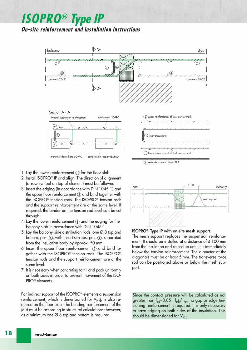
balcony slab
Section A - A
AA
a
aa
b
c
b
c
c
c
b
b
tension rod ISOPRO
compression support ISOPROtransverse force bars ISOPRO
integral suspension reinforcement upper reinforcement of steel bars or mesh
lower reinforcement of steel bars or mesh
insert stirrup Oslash 8
d
d secondary reinforcement Oslash 8
concrete concrete
100
mesh support
floor balcony
1 Lay the lower reinforcement for the floor slab2 Install ISOPROreg IP and align The direction of alignment
(arrow symbol on top of element) must be followed3 Insert the edging (in accordance with DIN 1045-1) and
the upper floor reinforcement and bind together withthe ISOPROreg tension rods The ISOPROreg tension rodsand the support reinforcement are at the same level Ifrequired the binder on the tension rod level can be cutthrough
4 Lay the lower reinforcement and the edging for thebalcony slab in accordance with DIN 1045-1
5 Lay the balcony-side distribution rods one Oslash 8 top andbottom pos with insert stirrups pos separatedfrom the insulation body by approx 50 mm
6 Insert the upper floor reinforcement and bind to-gether with the ISOPROreg tension rods The ISOPROreg
tension rods and the support reinforcement are at thesame level
7 It is necessary when concreting to fill and pack uniformlyon both sides in order to prevent movement of the ISO-PROreg elements
ISOPROreg Type IP with on-site mesh supportThe mesh support replaces the suspension reinforce-ment It should be installed at a distance of le 100 mmfrom the insulation and raised up until it is immediatelybelow the tension reinforcement The diameter of thediagonals must be at least 5 mm The transverse forcerod can be positioned above or below the mesh sup-port
Since the contact pressure will be calculated as notgreater than fcd=085 middot fck γc no gap or edge ten-sioning reinforcement is required It is only necessaryto have edging on both sides of the insulation Thisshould be dimensioned for VRd
For indirect support of the ISOPROreg elements a suspensionreinforcement which is dimensioned for VRd is also re-quired on the floor side The bending reinforcement of thejoist must be according to structural calculations howeveras a minimum one Oslash 8 top and bottom is required
wwwh-baucom18
ISOPROreg Type IPOn-site reinforcement and installation instructions
balcony slab
upper reinforcement of steel bars or mesh
lower reinforcement of steel bars or mesh
insert stirrup Oslash 8A
Aa
b
c
a
c
b
section A - A
a
c
b
transverse force bars ISOPRO compression strut ISOPRO
integral suspension reinforcement tension rod ISOPRO
d
d
b
c
concrete concrete
secondary reinforcement Oslash 8
1 Lay the lower reinforcement for the floor slab2 Install ISOPROreg IPT and align The direction of alignment (arrow symbol on top of element) must be followed3 Insert the edging (in accordance with DIN 1045-1) and the upper floor reinforcement and bind together with the
ISOPROreg tension rods The ISOPROreg tension rods and the support reinforcement are at the same level If requiredthe binder on the tension rod level can be cut through
4 Lay the lower reinforcement and the edging for the balcony slab in accordance with DIN 1045-15 Lay the balcony-side distribution rods one Oslash 8 top and bottom pos with insert stirrups pos separated from
the insulation body by approx 50 mm6 Insert the upper floor reinforcement and bind together with the ISOPROreg tension rods The ISOPROreg tension rods
and the support reinforcement are at the same level7 It is necessary when concreting to fill and pack uniformly on both sides in order to prevent movement of the ISOPROreg
elements
For indirect support of the ISOPROreg elements a suspension reinforcement which is dimensioned for VRd is also requiredon the floor side The bending reinforcement of the joist must be according to structural calculations however as a mi-nimum one Oslash 8 top and bottom is required
Since the contact pressure will be calculated as not greater than fcd=085 middot fck γc no gap or edge tensioning rein-forcement is required It is only necessary to have edging on both sides of the insulation This should be dimensionedfor VRd
ISOPROreg - Insulation at the highest level
ISOPROreg Type IPTOn-site reinforcement and installation instructions
for superior solutions
19
ISOPROreg Type IPOn-site reinforcement and installation instructions
balcony
slab
wall
balcony
h lt
80
ab
c
a
b
c
aa
a
a
b
c
b
c
a
a
bb
a
c
c
ee
d
d
b
b
upper reinforcement of steel bars or mesh
lower reinforcement of steel bars or mesh
closed stirrup
inse
rt s
tirru
p
reinforcement
upper reinforcement of steel bars or mesh
lower reinforcement of steel bars or mesh
closed stirrup
upper reinforcement of steel bars or mesh
lower reinforcement of steel bars or mesh
clos
ed s
tirru
p
insert stirrup
parallel reinforcement
ain
sert
stir
rup
b
reinforcementb
wall
balcony wall
balcony
slab
balcony
slab
ndash If the height offset is less than 80 mm a standardelement can also be used
ndash In this case a stirrup reinforcement with an upper leglength gt ls is required to deflect the tensile force onthe floor side
ndash Dimensioning the stirrup reinforcement for the can-tilever effects and transverse forces from the balcony
slabndash For connection reinforcement on the balcony side see
page 1819ndash The necessary transverse reinforcement in the overlap
area must be proved in accordance with DIN 1045-1ndash Recommended joist width at least 200 mm
Connection to a ldquomarginallyrdquo height-offset floor slab
balcony
slab
wall
balcony
h lt
80
ab
c
a
b
c
a
a
a
a
b
c
b
c
a
a
bb
a
c
c
ee
d
d
b
b
upper reinforcement of steel bars or mesh
lower reinforcement of steel bars or mesh
closed stirrup
inse
rt s
tirru
p
reinforcement
upper reinforcement of steel bars or mesh
lower reinforcement of steel bars or mesh
closed stirrup
upper reinforcement of steel bars or mesh
lower reinforcement of steel bars or mesh
clos
ed s
tirru
p
insert stirrup
parallel reinforcement
ain
sert
stir
rup
b
reinforcementb
wall
balcony wall
balcony
slab
balcony
slab
ndash The ISOPROreg tension rods comply with the necessaryoverlap length ls given in DIN 1045-1
ndash For connection reinforcement on the balcony side seepage 1819
ndash The necessary transverse reinforcement in the overlaparea must be proved in accordance with DIN 1045-1
ndash The minimum wall thickness is dependent on the type
Connection to a vertical wall ndash connection downwards
balcony
slab
wall
balcony
h lt
80
ab
c
a
b
c
a
a
a
a
b
c
b
c
a
a
bb
a
c
c
ee
d
d
b
b
upper reinforcement of steel bars or mesh
lower reinforcement of steel bars or mesh
closed stirrup
inse
rt s
tirru
p
reinforcement
upper reinforcement of steel bars or mesh
lower reinforcement of steel bars or mesh
closed stirrup
upper reinforcement of steel bars or mesh
lower reinforcement of steel bars or mesh
clos
ed s
tirru
p
insert stirrup
parallel reinforcement
ain
sert
stir
rup
b
reinforcementb
wall
balcony wall
balcony
slab
balcony
slab
ndash The ISOPROreg tension rods comply with the necessaryoverlap length ls given in DIN 1045-1
ndash For connection reinforcement on the balcony side seepage 1819
ndash The necessary transverse reinforcement in the overlaparea must be proved in accordance with DIN 1045-1
ndash The minimum wall thickness is dependent on the type
Connection to a vertical wall ndash connection upwards
wwwh-baucom20
ISOPROreg
Special types Valid for type series IP and IPT (analogously)
balcony
slab
wall
balcony
h lt
80
ab
c
a
b
c
a
a
a
a
b
c
b
c
a
a
bb
a
c
c
ee
d
d
b
b
upper reinforcement of steel bars or mesh
lower reinforcement of steel bars or mesh
closed stirrup
inse
rt s
tirru
p
reinforcement
upper reinforcement of steel bars or mesh
lower reinforcement of steel bars or mesh
closed stirrup
upper reinforcement of steel bars or mesh
lower reinforcement of steel bars or mesh
clos
ed s
tirru
p
insert stirrup
parallel reinforcement
ain
sert
stir
rup
b
reinforcementb
wall
balcony wall
balcony
slab
balcony
slab
ndash dimensioning of the stirrup reinforcement for can-tilever effect and transverse force on the balcony slab
ndash the ISOPROreg tension rods comply with the DIN 1045-1 requirement for overlap length ls
ndash for on-site reinforcement see pages 1819
ndash the required transverse reinforcement in the overlapzone must be proven in compliance with DIN 1045-1
ndash recommended step-down width at least 220 mm
Connection to a floor slab with a step-up offset
balcony
slab
wall
balcony
h lt
80
ab
c
a
b
c
a
a
a
a
b
c
b
c
a
a
bb
a
c
c
ee
d
d
b
b
upper reinforcement of steel bars or mesh
lower reinforcement of steel bars or mesh
closed stirrup
inse
rt s
tirru
p
reinforcement
upper reinforcement of steel bars or mesh
lower reinforcement of steel bars or mesh
closed stirrup
upper reinforcement of steel bars or mesh
lower reinforcement of steel bars or mesh
clos
ed s
tirru
p
insert stirrup
parallel reinforcementa
inse
rt s
tirru
p
b
reinforcementb
wall
balcony wall
balcony
slab
balcony
slab
ndash dimensioning of the stirrup reinforcement for can-tilever effect and transverse force on the balcony slab
ndash the ISOPROreg tension rods comply with the DIN 1045-1 requirement for overlap length ls
ndash for on-site reinforcement see pages 1819
ndash the required transverse reinforcement in the overlapzone must be proven in compliance with DIN 1045-1
ndash constructive angle reinforcement pos 3ndash recommended step-down width at least 220 mm
Connection to a floor slab with step-down offset
ISOPROreg - Insulation at the highest level
for superior solutions
21
ISOPROreg
Special types Valid for type series IP and IPT (analogously)
After stripping freely-protruding concrete slabs experience a lowering of the slab edge This displacement is a com-bination of the deformation of the balcony insulation elements used and the bending of the slab itself These two de-formations are superimposed and compensated by raising the formworkThe calculations shown below give the required formwork height offset at the end of the cantilever which results fromthe ISOPROreg elements at 100 loading For the total height offset the slab deformation should be added in accor-dance with DIN 1045-1 The total height offset defined in the construction plans from the structural design engineershould take into account the planned direction of the drainage when rounding off the results
wwwh-baucom22
ISOPROreg
Deflection and height offset
Element height h [mm] IP 88IP 107IP 108
IP 127IP 128IP 129
IP 1210
IPT 1211IPT 1212IPT 1412
IPT 1414Concrete covering cv
30 35 40 45 50160 051 059 092 106
160 048 056 087 100160 170 045 053 082 094
160 170 043 050 077 089160 170 180 041 047 073 084
170 180 039 045 070 080170 180 190 037 043 067 079
180 190 035 041 064 073180 190 200 034 039 061 069
190 200 033 038 059 067190 200 210 031 036 056 064
200 210 030 035 054 062200 210 220 029 034 052 059
210 220 028 033 050 057210 220 230 027 031 049 055
220 230 026 030 047 053220 230 240 026 029 046 052
230 240 025 029 044 050230 240 250 024 028 043 049
240 250 023 027 042 047240 250 023 026 040 046
250 022 025 039 045250 021 025 038 043
Offset height of the balcony slab
ISOPROreg - Insulation at the highest level
for superior solutionsISOPROreg
Deflection and height offset
Example for defining the balcony slab height offset
mEd bending moment used to determine the height offset resulting from the ISOPROreg elementThe definitive load combination is decided by the structural engineer
mRd design moment of the ISOPROreg element taken from the dimensioning table on pages 16 and 17lk Cantilever length in [m]
ExampleCantilever length lk = 180 mSlab thickness h = 180 mmIntrinsic weight (slab and covering) g = 60 kNm2
Edge load (parapet) F = 15 kNmLive load p = 40 kNm2
Concrete covering cv = 30 mm
Design calculationsmEd= (g + p) x lk2 2 + F x lk = (60 middot 135 + 40 middot 15) middot 182 2 + 15 middot 18 middot 135 = 265 kNmmvEd = (g + p) x lk + F = (60 middot 135 + 40 middot 15) middot 18 + 15 middot 135 = 274 kNm
Selected ISOPROreg IP 127 cv 30 h = 180 mm mRd = 289 kNmm vRd = 415 kNm
Selected load combination for determination of the height offset resulting from the ISOPROreg element mEd= (g + p3) middot lk22 + F middot lk= (60 middot 135 + 403 middot 15) middot 182 2 + 15 middot 18 middot 135 =200 kNmm
uuml = 041 middot (265 289) middot 180 middot 10 = 67 mm
23
uuml [mm] = value from table middot (mEdmRd) middot lk [m] middot 10
wwwh-baucom24
The external concrete components must have expansion joints at right angles to the insulation layer in order to limitthe stress caused by changes in temperature The spacing of the joints e is given in the following table
balcony
ISOPRO ISOPRO
expansion joint
balcony
e 2
e 2
ISOPRO Type IPT Corner
expansion joint
seperation ofexpansion joints e
seperation ofexpansion joints e
expansion jointExpansion joint spacing for ISOPROreg Types IP und IPT
Rod diameter [mm] le 10 12 14 16 20
Joint spacing e [m] 130 113 101 92 80
balcony
ISOPRO ISOPRO
expansion joint
balcony
e 2
e 2
ISOPRO Type IPT Corner
expansion joint
seperation ofexpansion joints e
seperation ofexpansion joints e
expansion joint
expansion joint dowellingeg HED-S + plastic sleeves
ISOPROreg
Expansion joint spacing
For corner constructions the maximum rod leg length is e2
ISOPROreg - Insulation at the highest level
for superior solutions
25
a a
b
c
b
c
sup3100
In pre-cast units
Arrange the lower reinforcement layer including themesh support as per structural design Distance to in-sulation joint le 100 mm (applies to IP only)
Install lower section The last transverse rod in themesh must be placed as close as possible to the insula-tion observing the required concrete covering
For IP the transverse force rod can be under or on topof the mesh The mesh support should be lifted until itis underneath the tension reinforcement
Concrete the slab element
Locate and fix the associated upper section andwhere required intermediate section
Type IP is supplied with suspension reinforcement asstandard
On-site
Lay the necessary on-site reinforcement on the floorside
Lay the slab element on the pre-prepared timberbeams
Lay the necessary on-site reinforcement on the bal-cony side
Attach the associated upper section and where re-quired intermediate section Bind the tension strutto the on-site reinforcement
h = 210 to 250 mm
Important note fit additional insertion stirrups Oslash 620 or stirrup meshQ188A on the balcony side
In type IP pre-cast units In type IPT pre-cast units
a a
b
c
b
c
sup3100
Type IP on-site Type IPT on-site
Important noteThe type identification for lower and upper sections must match (see also colour identification) The direction of in-stallation (on the balcony side) is mandatory
ISOPROreg
Two-part elements
wwwh-baucom26
upper section
centre section
lower section
upper section
centre section
lower section
balcony balconyslab slab
Type IP Type IPT
Construction
All ISOPROreg elements of types IP and IPT can be supplied as two-part elements
General notes
ndash The permitted resultant stresses can be found in thetables on pages 16 and 17 of this technical information
ndash Intermediate sections can be supplied for height offsetcompensation in 20 and 40 mm thicknesses
ndash Type IP If the mesh supports are placed with a spacingof le 100 mm from the insulation joint no additionalsuspension reinforcement is required Instead asuspension reinforcement dimensioned for VRd shouldbe located along the insulation joints
ndash For information regarding the required formwork height off-set and the maximum spacing of expansion joints refer topages 22 23 and 24
ndash The adhesive labels (type designation) for the upper andlower sections must be identical Follow the instructions forthe balcony side and the floor side
The following elements also have an addi-tional colour coding
ISOPROreg Type Colour code
IP 107 greenIP 127 blueIP 128 yellowIP 1210 white
The continuity of the colour coding throughthe elements ensures correct matching everytime even for short sections
ISOPROreg
Two-part elements
ISOPROreg - Insulation at the highest level
for superior solutions
27
balcony sidebalcony side
section 1st position
section 2nd position
slab balcony
1st position
2nd
posi
tion
cv
cvslab balcony
slab balcony
section 1st position
section 2nd position
1st position
2nd
posi
tion
slab balcony
IPT 127 Corner 820mmIPT 1210 Corner 960mm
IPT 127 Corner 820mmIPT 1210 Corner 960mm
IPT
127
Cor
ner
820m
mIP
T 12
10
Cor
ner
960m
mIP
T 12
7 C
orne
r82
0mm
IPT
121
0 C
orne
r96
0mm
General notes
Area of application for type IPT-Corner from slab thickness h le 180 mmOn-site reinforcement using overlap joints in accordance with DIN 1045-12001-07 Section 126Please refer to the information regarding on-site reinforcement on page 29Special elements for h = 160 mm are possibleBecause of the compression level a minimum spacing of the floor-side filigree slabs from the insulation body of185 mm is required for the ISOPROreg IPT-Corner elements
Type Length of element [m] Tension rods Compression level Transverse force rods
IPT 107-Corner 050 + 050 5 Oslash 10 + 5 Oslash 10 2 x 4 compression block 2 Oslash 10 + 2 Oslash 10
IPT 127-Corner 062 + 062 6 Oslash 12 + 6 Oslash 12 12 Oslash 14 + 12 Oslash 14 3 Oslash 10 + 3 Oslash 10
IPT 1210-Corner 062 + 062 6 Oslash 14 + 6 Oslash 14 14 Oslash 14 + 14 Oslash 14 3 Oslash 12 + 3 Oslash 12
Configuration of the elements
IPT 107-Corner
ISOPROreg Type IPT EckConstruction and dimensions
wwwh-baucom28
Plate thickness [mm] referred to cv [mm] Dimensional values for acceptable load moments MRd [kNm]
30 35 IPT 107 Corner IPT 127 Corner IPT 1210 Corner- 180 169 277 320
180 - 178 292 337- 190 186 306 354
190 - 195 320 370- 200 203 335 387
200 - 212 349 404- 210 220 363 421
210 - 229 378 437- 220 237 392 454
220 - 246 406 471- 230 254 421 487
230 - 263 435 504- 240 271 449 521
240 - 280 463 537- 250 289 478 554
250 - 297 492 571Dimensional values for acceptable transverse forces VRd [kN]
h = 180 - 250 [mm] 483 724 1043
balcony sidebalcony side
section 1st position
section 2nd position
slab balcony
1st position
2nd
posi
tion
cv
cvslab balcony
slab balcony
section 1st position
section 2nd position
1st position
2nd
posi
tion
slab balcony
IPT 127 Corner 820mmIPT 1210 Corner 960mm
IPT 127 Corner 820mmIPT 1210 Corner 960mm
IPT
127
Cor
ner
820m
mIP
T 12
10
Cor
ner
960m
mIP
T 12
7 C
orne
r82
0mm
IPT
121
0 C
orne
r96
0mm
Dimensioning table for concrete gege C2025
IPT 127-CornerIPT 1210-Corner
ISOPROreg Type IPT CornerConstruction and dimensions
ISOPROreg - Insulation at the highest level
for superior solutions
29
1st position
2nd
posi
tion
balcony slab
a
da
b b
c c
dstarter bar 1st position supplementary reinforcement
supplementary reinforcement
supp
lem
enta
ry r
einf
orce
men
t
supp
lem
enta
ry r
einf
orce
men
t
starter bar 1st position
stra
ter
bar
2nd
posi
tion
star
ter
bar
2nd
posi
tion
Type IPT 107-Corner IPT 127-Corner IPT 1210-Corner
starter bar 1st position 5 Oslash 10 6 Oslash 12 6 Oslash 14
starter bar 2nd position 5 Oslash 10 6 Oslash 12 6 Oslash 14
Supplementaryreinforcement 5 Oslash 10 6 Oslash 12 6 Oslash 14
Supplementaryreinforcement 5 Oslash 10 6 Oslash 12 6 Oslash 14
extension of the tension reinforcement internally as well as externally length = 2 x balcony cantilever length
ISOPROreg Type IPT CornerOn-site reinforcement
wwwh-baucom30
ISOPROreg - Insulation at the highest level
for superior solutions
IPQ IPQIPH
IPH
IPH
IPH
IPQS IPQSIPH IPQQS IPQQSIPH
IPQ IPQ
IPQ
IPQQ IPQQ
IPQQ IPQQIP
QS
IPQ IPQ
IPQ
Z
IPQ
S tie rod inlower position
IPQQ IPQQ
IPQ
Z
IPQ
S tie rod inlower position
propped balcony
internal-corner balcony with props
ISOPROreg
Examples of transverse force elements
propped balcony
propped balcony with selective point connection
internal-corner balcony with props
inset balcony with tieback3-sided overlying loggia with tieback
propped balcony with selective point connection
31
wwwh-baucom32
1000
1000
balcony slab balcony slab
IPQ 86 495 mmIPQ 88 495 mmIPQ 106 615 mmIPQ 126 740 mm
IPQ 86 495 mmIPQ 88 495 mmIPQ 106 615 mmIPQ 126 740 mm80
370 80 150
Calculated values for acceptable transverse forces vRd [kNm]
Element height IPQ 64 IPQ 65 IPQ 66 IPQ 68 IPQ 610
160 - 250 mm 348 435 522 695 869
Type IPQ 64 IPQ 65 IPQ 66 IPQ 68 IPQ 610Length [mm] 1000 1000 1000 1000 1000
Transverse force rods 4 Oslash 6 5 Oslash 6 6 Oslash 6 8 Oslash 6 10 Oslash 6
Compression blocks 4 4 4 4 4needed As [cmsup2] 08 10 12 16 20
Dimensioning table - Type IPQ for concrete gege C2025
Configuration of the elements Type IPQ
section
Top view
ISOPROreg Type IPQConstruction and dimensions
IPQ 64 - 610
min Element hight depentend on rod diameter Oslash 10 h ge170 Oslash 12 h ge180 Oslash 14 h ge190
ISOPROreg - Insulation at the highest level
for superior solutions
33
balcony slab
upper reinforcement of steel bars or mesh
lower reinforcement of steel bars or mesh
transverse shear force reinforcement 2 Oslash 8
insert stirrup
ls ls
a
b
c
d
d
a
c
d
b
suspension reinforcemente
ed
secondary reinforcement 2 Oslash 8
concrete concrete
The on-site suspension reinforcement pos and should be calculated for VRd (cf type test No 0519) and loca-ted next to the transverse force rods A Oslash 8 mm steel distribution rod should be installed above and below The sus-pension reinforcement can be replaced by a mesh support (see type IP page 18)DIN 1045-1 Section 1033 applies to the proof of the transverse force capacity of the slabs without shear reinforce-ment For proof of the transverse force capacity of the slabs with shear reinforcement DIN 1045-1 Section 1034 ap-plies The maximum transmissible transverse force across the joints must be limited to 03 VRdmax zu begrenzen
ISOPROreg Type IPQOn-site reinforcement
Calculated values for acceptable transverse forces vRd [kNm]
Element height IPQ 86 IPQ 88 IPQ 106 IPQ 125 IPQ 126
160 - 250 mm 927 1236 1449 1739 2089
Type IPQ 86 IPQ 88 IPQ 106 IPQ 125 IPQ 126Length [mm] 1000 1000 1000 1000 1000
Transverse force rods 6 Oslash 8 8 Oslash 8 6 Oslash 10 5 Oslash 12 6 Oslash 12
Compression blocks 4 4 4 4 4needed As [cmsup2] 21 28 33 40 48
Configuration of the elements Type IPQ
min Element hight depentend on rod diameter Oslash 10 h ge170 Oslash 12 h ge180 Oslash 14 h ge190
wwwh-baucom34
ISOPROreg Type IPQS 2Construction and dimensions
balcony slab
balcony slab
Calculated values for acceptable transverse forces VRd [kN]
Element height IPQS 62 IPQS 82 IPQS 102 IPQS 122 IPQS 142
160 - 250 mm 174 309 483 695 947
Dimensioning table - Type IPQS2 for concrete gege C2025
Type IPQS 62 IPQS 82 IPQS 102 IPQS 122 IPQS 142
Element length [mm] 300 300 300 300 300
Transverse force rods 2 Oslash 6 2 Oslash 8 2 Oslash 10 2 Oslash 12 2 Oslash 14
Compression rods 2 Oslash 10 2 Oslash 10 3 Oslash 10 4 Oslash 12 4 Oslash 14needed As [cmsup2] 040 071 111 160 218
Configuration of the elements Type IPQS2
min Element height dependent on rod diameter Oslash 10 h ge170 Oslash 12 h ge180 Oslash 14 h ge190
IPQS 82 495mmIPQS102 615mmIPQS122 740mmIPQS 142 860mm
IPQS 62
IPQS 82 495mmIPQS102 615mmIPQS122 740mmIPQS 142 860mm
ISOPROreg - Insulation at the highest level
for superior solutions
35
Calculated values for acceptable transverse forces VRd [kN]
Element height IPQS 63 IPQS 83 IPQS 103 IPQS 123 IPQS 143
160 - 250 mm 261 464 724 1043 1420
Dimensioning table - Type IPQS3 for concrete gege C2025
Type IPQS 63 IPQS 83 IPQS 103 IPQS 123 IPQS 143
Element length [mm] 400 400 400 400 400
Transverse force rods 3 Oslash 6 3 Oslash 8 3 Oslash 10 3 Oslash 12 3 Oslash 14
Compression rods 2 Oslash 10 3 Oslash 10 4 Oslash 12 5 Oslash 12 6 Oslash 14needed As [cmsup2] 060 107 167 240 327
Configuration of the elements Type IPQS3
balcony slab
balcony slab
ISOPROreg Type IPQS 3Construction and dimensionsn
IPQS 83 495mmIPQS103 615mmIPQS123 740mmIPQS 143 860mm
IPQS 63
IPQS 83 495mmIPQS103 615mmIPQS123 740mmIPQS 143 860mm
min Element height dependent on rod diameter Oslash 10 h ge170 Oslash 12 h ge180 Oslash 14 h ge190
wwwh-baucom36
ISOPROreg Type IPQQConstruction and dimensions
1000
1000
balcony balconyslab slab
180 80 150 80165 165
370 80 80150
IPQQ 86 495 mmIPQQ 106 615 mmIPQQ 126 740 mm
IPQQ 86 495 mmIPQQ 106 615 mmIPQQ 126 740 mm
IPQQ 64 IPQQ 66IPQQ 68 IPQQ 610
Calculated values for acceptable transverse forces vRd [kNm]
Element height IPQQ 64 IPQQ 66 IPQQ 68 IPQQ 610 IPQQ 86 IPQQ 106 IPQQ 126
160 - 250 mm plusmn348 plusmn522 plusmn695 plusmn869 plusmn927 plusmn1449 plusmn2086
Type IPQQ 64 IPQQ 66 IPQQ 68 IPQQ 610 IPQQ 86 IPQQ 106 IPQQ 126Element length [mm] 500 + 500 500 + 500 500 + 500 500 + 500 500 + 500 500 + 500 500 + 500Transverse force rods 2x4 Oslash 6 2x6 Oslash 6 2x8 Oslash 6 2x10 Oslash 6 2x6 Oslash 8 2x6 Oslash 10 2x6 Oslash 12
Compression rods 4 Oslash 10 4 Oslash 10 6 Oslash 10 6 Oslash 10 6 Oslash 10 10 Oslash 10 10 Oslash 12needed As [cmsup2] 080 120 160 200 213 333 480
Dimensioning table - Type IPQQ for concrete gege C2025
Configuration of the elements Typ IPQQ
Top view
Section
min Element height dependent on rod diameter Oslash 10 h ge170 Oslash 12 h ge180 Oslash 14 h ge190
ISOPROreg - Insulation at the highest level
for superior solutions
37
ISOPROreg Type IPQQOn-site reinforcement
balcony slab
upper reinforcement of steel bars or mesh
lower reinforcement of steel bars or mesh
ls ls
b
c
a
c
d
b
insert stirrupa
d
dinsert stirrupa
ad
d
secondary reinforcement 2 Oslash 8
concrete concrete
secondary reinforcement 2 Oslash 8
The on-site suspension reinforcement pos should be calculated for VRd and located next to the transverse forcerods A Oslash 8 mm steel distribution rod should be installed above and below DIN 1045-1 Section 1033 applies to the proof of the transverse force capacity of the slabs without shear reinforce-ment For proof of the transverse force capacity of the slabs with shear reinforcement DIN 1045-1 Section 1034 ap-plies The maximum transmissible transverse force across the joints must be limited to 03 VRdmax
wwwh-baucom38
ISOPROreg Type IPQQS 2Construction and dimensions
balcony slab
balcony slab
Calculated values for acceptable transverse forces VRd [kN]
Element height IPQQS 62 IPQQS 82 IPQQS 102 IPQQS 122 IPQQS 142
160 - 250 mm plusmn174 plusmn309 plusmn483 plusmn695 plusmn947
Dimensioning table - Type IPQQS2 for concrete gege C2025
Type IPQQS 62 IPQQS 82 IPQQS 102 IPQQS 122 IPQQS 142
Element length [mm] 300 300 300 300 300
Transverse force rods 2x 2 Oslash 6 2x 2 Oslash 8 2x 2 Oslash 10 2x 2 Oslash 12 2x 2 Oslash 14
Compression rods 2 Oslash 10 2 Oslash 10 3 Oslash 10 4 Oslash 12 4 Oslash 14needed As [cmsup2] 040 071 111 160 218
Configuration of the elements Type IPQQS2
IPQQS 82 495mmIPQQS 102 615mmIPQQS 122 740mmIPQQS 142 860mm
IPQQS 62
IPQQS 82 495mmIPQQS 102 615mmIPQQS 122 740mmIPQQS 142 860mm
min Element height dependent on rod diameter Oslash 10 h ge170 Oslash 12 h ge180 Oslash 14 h ge190
ISOPROreg - Insulation at the highest level
for superior solutions
39
ISOPROreg Type IPQQS 3Construction and dimensions
balcony slab
balcony slab
Calculated values for acceptable transverse forces VRd [kN]
Element height IPQQS 63 IPQQS 83 IPQQS 103 IPQQS 123 IPQQS 143
160 - 250 mm plusmn261 plusmn464 plusmn724 plusmn1043 plusmn1420
Dimensioning table - Type IPQQS3 for concrete gege C2025
Type IPQQS 63 IPQQS 83 IPQQS 103 IPQQS 123 IPQQS 143
Element length [mm] 400 400 400 400 400
Transverse force rods 2x 3 Oslash 6 2x 3 Oslash 8 2x 3 Oslash 10 2x 3 Oslash 12 2x 3 Oslash 14
Compression rods 2 Oslash 10 3 Oslash 10 4 Oslash 12 5 Oslash 12 6 Oslash 14needed As [cmsup2] 060 107 167 240 327
Configuration of the elements Type IPQQS3
min Element height dependent on rod diameter Oslash 10 h ge170 Oslash 12 h ge180 Oslash 14 h ge190 alternatively in Element length 500 mm available
IPQQS 83 495mmIPQQS 103 615mmIPQQS 123 740mmIPQQS 143 860mm
IPQQS 63
IPQQS 83 495mmIPQQS 103 615mmIPQQS 123 740mmIPQQS 143 860mm
wwwh-baucom40
ISOPROreg Type IPTDConstruction and dimensions
IPTD IPTD
inset balcony
30
balcony slab
Top view
Section
Example
Table of Dimensions ndash Type IPTD [length in mm]
TypeTension rod Transverse force rod Compression rod Supplemental transverse force
ZL QL DL Q10L Q12LIPTD 126 820 497 820 617 742IPTD 127 820 497 820 617 742IPTD 1210 820 497 820 617 742IPTD 1212 820 497 820 617 742IPTD 1410 960 497 960 617 742
ISOPROreg - Insulation at the highest level
for superior solutions
41
ISOPROreg Type IPTDOn-site reinforcement
balcony slab
upper reinforcement of steelbars or mesh
lower reinforcement of steelbars or mesh
secondary reinforcement 2 Oslash 8
secondary reinforcement 2 Oslash 8
insert stirrup
ls ls
AA
a
b
c
d
d
a
c
d
b
lower reinforcement of steelbars or meshc
upper reinforcement of steelbars or meshb
d
insert stirrupee
b
c
a
a
Section A - A
ISOPRO transverse force rods ISOPRO compression rods
ISOPRO transverse force rods ISOPRO tension rods
d
concrete concrete
The on-site suspension reinforcement pos should be calculated for VRd and located next to the transverse forcerods A Oslash 8 mm steel distribution rod should be installed above and below DIN 1045-1 Section 1033 applies to the proof of the transverse force capacity of the slabs without shear reinforce-ment For proof of the transverse force capacity of the slabs with shear reinforcement DIN 1045-1 Section 1034 ap-plies The maximum transmissible transverse force across the joints must be limited to 03 VRdmax
wwwh-baucom42
ISOPROreg Type IPTDDimensioning table for concrete gege C2025
Plate thickness [mm] withreference to cv [mm] Rated values for moment loading mRd [kNmm]
30 35 IPTD 126IPTD 126
Q10IPTD 126
Q12IPTD 127
IPTD 127Q10
IPTD 127Q12
IPTD 1210
- 160 plusmn 145 - - plusmn 182 - - plusmn 253160 - plusmn 154 - - plusmn 193 - - plusmn 269- 170 plusmn 162 plusmn 146 - plusmn 204 plusmn 187 - plusmn 284
170 - plusmn 171 plusmn 154 - plusmn 214 plusmn 197 - plusmn 299- 180 plusmn 180 plusmn 162 plusmn 145 plusmn 225 plusmn 208 plusmn 190 plusmn 314
180 - plusmn 189 plusmn 170 plusmn 152 plusmn 236 plusmn 218 plusmn 199 plusmn 330- 190 plusmn 197 plusmn 178 plusmn 159 plusmn 247 plusmn 228 plusmn 209 plusmn 345
190 - plusmn 206 plusmn 186 plusmn 166 plusmn 258 plusmn 238 plusmn 218 plusmn 360- 200 plusmn 215 plusmn 194 plusmn 173 plusmn 269 plusmn 248 plusmn 227 plusmn 375
200 - plusmn 223 plusmn 202 plusmn 180 plusmn 280 plusmn 258 plusmn 236 plusmn 391- 210 plusmn 232 plusmn 209 plusmn 187 plusmn 291 plusmn 268 plusmn 246 plusmn 406
210 - plusmn 241 plusmn 217 plusmn 194 plusmn 302 plusmn 278 plusmn 255 plusmn 421- 220 plusmn 250 plusmn 225 plusmn 201 plusmn 313 plusmn 288 plusmn 264 plusmn 437
220 - plusmn 258 plusmn 233 plusmn 208 plusmn 324 plusmn 298 plusmn 273 plusmn 452- 230 plusmn 267 plusmn 241 plusmn 215 plusmn 335 plusmn 308 plusmn 283 plusmn 467
230 - plusmn 276 plusmn 249 plusmn 222 plusmn 346 plusmn 318 plusmn 292 plusmn 482- 240 plusmn 285 plusmn 257 plusmn 229 plusmn 357 plusmn 328 plusmn 301 plusmn 498
240 - plusmn 293 plusmn 265 plusmn 236 plusmn 368 plusmn 339 plusmn 310 plusmn 513- 250 plusmn 302 plusmn 272 plusmn 243 plusmn 379 plusmn 349 plusmn 320 plusmn 528
250 - plusmn 311 plusmn 280 plusmn 250 plusmn 390 plusmn 359 plusmn 329 plusmn 543
Rated values for transverse force loading vRd [kNm]
h = 160 - 250 [mm ] plusmn 415 plusmn 762 plusmn 1098 plusmn 415 plusmn 762 plusmn 1098 plusmn 415
Type IPTD 126 IPTD 126Q10
IPTD 126Q12
IPTD 127 IPTD 127Q10
IPTD 127Q12
IPTD 1210
Element lenght [mm] 500 + 500 500 + 500 500 + 500 500 + 500 500 + 500 500 + 500 500 + 500
Tension rods 6 Oslash 12 6 Oslash 12 6 Oslash 122 Oslash 10 + 6 Oslash 12
2 Oslash 10 + 6 Oslash 12
2 Oslash 10 +6 Oslash 12
10 Oslash 12
Transverse forcerods
2x4 Oslash 8 2x4 Oslash 10 2x4 Oslash 12 2x4 Oslash 8 2x4 Oslash 10 2x4 Oslash 12 2x4 Oslash 8
Compression rods 6 Oslash 12 6 Oslash 12 6 Oslash 122 Oslash 10 + 6 Oslash 12
2 Oslash 10 +6 Oslash 12
2 Oslash 10 +6 Oslash 12
10 Oslash 12
Configuration of the elements Type IPTD
ISOPROreg - Insulation at the highest level
for superior solutions
43
ISOPROreg Type IPTDDimensioning table for concrete gege C2025
Rated values for moment loading mRd [kNmm]
IPTD 1210Q10
IPTD 1210Q12
IPTD 1212IPTD 1212
Q10IPTD 1212
Q12IPTD 1410
IPTD 1410Q10
IPTD 1410Q12
- - plusmn 307 - - plusmn 349 - -- - plusmn 326 - - plusmn 371 - -
plusmn 268 - plusmn 345 plusmn 328 - plusmn 392 plusmn 377 -plusmn 282 - plusmn 363 plusmn 346 - plusmn 414 plusmn 397 -plusmn 297 plusmn 279 plusmn 382 plusmn 364 plusmn 346 plusmn 436 plusmn 418 plusmn 401plusmn 311 plusmn 293 plusmn 400 plusmn 381 plusmn 363 plusmn- 457 plusmn 439 plusmn 421plusmn 325 plusmn 306 plusmn 419 plusmn 399 plusmn 380 plusmn 479 plusmn 459 plusmn 441plusmn 340 plusmn 320 plusmn 437 plusmn 417 plusmn 397 plusmn 500 plusmn 480 plusmn 461plusmn 354 plusmn 333 plusmn 456 plusmn 434 plusmn 414 plusmn 522 plusmn 501 plusmn 480plusmn 369 plusmn 347 plusmn 474 plusmn 452 plusmn 430 plusmn 543 plusmn 522 plusmn 500plusmn 383 plusmn 361 plusmn 493 plusmn 470 plusmn 447 plusmn 565 plusmn 542 plusmn 520plusmn 397 plusmn 374 plusmn 511 plusmn 487 plusmn 464 plusmn 587 plusmn 563 plusmn 540plusmn 412 plusmn 388 plusmn 530 plusmn 505 plusmn 481 plusmn 608 plusmn 584 plusmn 560plusmn 426 plusmn 401 plusmn 548 plusmn 523 plusmn 498 plusmn 630 plusmn 604 plusmn 580plusmn 440 plusmn 415 plusmn 567 plusmn 540 plusmn 515 plusmn 351 plusmn 625 plusmn 600plusmn 455 plusmn 428 plusmn 585 plusmn 558 plusmn 531 plusmn 673 plusmn 646 plusmn 619plusmn 469 plusmn 442 plusmn 604 plusmn 576 plusmn 548 plusmn 694 plusmn 666 plusmn 639plusmn 484 plusmn 455 plusmn 622 plusmn 593 plusmn 565 plusmn 716 plusmn 687 plusmn 659plusmn 498 plusmn 469 plusmn 641 plusmn 611 plusmn 582 plusmn 737 plusmn 708 plusmn 679plusmn 512 plusmn 483 plusmn 659 plusmn 629 plusmn 599 plusmn 759 plusmn 728 plusmn 699
Rated values for transverse force loading vRd [kNm]
plusmn 762 plusmn 1098 plusmn 415 plusmn 762 plusmn 1098 plusmn 415 plusmn 762 plusmn 1098
IPTD 1210Q10
IPTD 1210Q12
IPTD 1212 IPTD 1212Q10
IPTD 1212Q12
IPTD 1410 IPTD 1410Q10
IPTD 1410Q12
500 + 500 500 + 500 500 + 500 500 + 500 500 + 500 500 + 500 500 + 500 500 + 500
10 Oslash 12 10 Oslash 12 12 Oslash 12 12 Oslash 12 12 Oslash 12 10 Oslash 14 10 Oslash 14 10 Oslash 14
2x4 Oslash 10 2x4 Oslash 12 2x4 Oslash 8 2x4 Oslash 10 2x4 Oslash 12 2x4 Oslash 8 2x4 Oslash 10 2x4 Oslash 12
10 Oslash 12 10 Oslash 12 12 Oslash 12 12 Oslash 12 12 Oslash 12 10 Oslash 14 10 Oslash 14 10 Oslash 14
wwwh-baucom44
ISOPROreg Type IPQZConstruction and dimensions
300
40
0
300
40
0
balcony slab
balcony slab
For restraint-free support with an IPQZ element it should be opposed by an IPQS element Both elements should bereinforced by a tieback which corresponds in diameter and rod count to the IPQS and IPQZAn on-site stirrup reinforcement is required to connect IPQS to the floor
Calculated values for acceptable transverse forces VRd [kN]
Element height IPQZ 62 IPQZ 82 IPQZ 102 IPQZ 122 IPQZ 142
160 - 250 mm 174 309 483 695 947
IPQZ 63 IPQZ 83 IPQZ 103 IPQZ 123 IPQZ 143
160 - 250 mm 261 464 724 1043 1420
Dimensioning table ndash Type IPQZ for concrete ge C2025
Type IPQZ 62 IPQZ 82 IPQZ 102 IPQZ 122 IPQZ 142Element lenght [mm] 300 300 300 300 300
Transverse force rods 2 Oslash 6 2 Oslash 8 2 Oslash 10 2 Oslash 12 2 Oslash 14
Configuration of the elements
Type IPQZ 63 IPQZ 83 IPQZ 103 IPQZ 123 IPQZ 143Element length [mm] 400 400 400 400 400
Transverse force rods 3 Oslash 6 3 Oslash 8 3 Oslash 10 3 Oslash 12 3 Oslash 14
min Element height dependent on rod diameter Oslash 10 h ge170 Oslash 12 h ge180 Oslash 14 h ge190
IPQZ 82 83 495mmIPQZ102 103 615mmIPQZ122 123 740mmIPQZ 142 143 860mm
IPQZ 82 83 495mmIPQZ102 103 615mmIPQZ122 123 740mmIPQZ 142 143 860mm
IPQZ 62 63
ISOPROreg - Insulation at the highest level
for superior solutions
45
ISOPROreg Type IPQZOn-site reinforcement
Type Tieback Insert stirrup for use with
IPQZ 62 2 Oslash 6 1 Oslash 6 IPQS 62
IPQZ 82 2 Oslash 8 1 Oslash 8 IPQS 82
IPQZ 102 2 Oslash 10 1 Oslash 10 IPQS 102
IPQZ 122 2 Oslash 12 2 Oslash 8 IPQS 122
IPQZ 142 2 Oslash 14 2 Oslash 10 IPQS 142
tie roda
b
stirrup for anchering tie rodb
a
slab slabbalcony
Typ IPQZ Typ IPQS
Type Tieback Insert stirrup for use with
IPQZ 63 3 Oslash 6 2 Oslash 6 IPQS 63
IPQZ 83 3 Oslash 8 2 Oslash 8 IPQS 83
IPQZ 103 3 Oslash 10 2 Oslash 10 IPQS 103
IPQZ 123 3 Oslash 12 3 Oslash 8 IPQS 123
IPQZ 143 3 Oslash 14 3 Oslash 10 IPQS 143
wwwh-baucom46
ISOPROreg Type IPHConstruction and dimensions
The ISOPROreg elements type IPH which absorb horizontal forces must only be used with ISOPROreg cantilever slabs ortransverse force connections
The number of IPH elements to be used is defined by the structural engineer whereby the expansion joint spacing mustbe maintained
When using ISOPROreg IPH elements the force absorption of the line connection must be reduced by the ratio of thelength of the IPH elements to the total connection length as a percentage
independent of cvReinforcement Length of
element
HRd
Transverse force Horizontal Transverse force Horizontal
IPH 1 2 x 1 Oslash 8 - 100 mm plusmn 74 kN -IPH 2 - 1 Oslash 10 100 mm - plusmn181 kNIPH 3 2 x 1 Oslash 8 1 Oslash 10 100 mm plusmn 74 kN plusmn 181 kN
Dimensioning table ndash Type IPH for concrete gege C2025
balcony slab
balcony slab
balcony slab
balcony slab
balcony slab
balcony slab
100
100
100
250 80 250
250 80 250
250 80 250IPH 1 for absorption of horizontal forces parallel to the insulation joint
IPH 2 for absorption of horizontal forces perpendicular to the insulation joint
IPH 3 for absorption of horizontal forces parallel and perpendicular to the insulation joint
ISOPROreg - Insulation at the highest level
for superior solutions
47
ISOPROreg Type IPHOn-site reinforcement
The installation of the ISOPROreg IPH elements is analogous to the installation of the ISOPROreg cantilever slabs or trans-verse force connectionsThe number and positions of the elements are defined in the structural detail The elements must be fixed in their posi-tions
plate slab balcony slab
ls ls
lower reinforcement of steel bars or mesh
d
lower reinforcement of steel bars or mesh
upper reinforcement of steel bars or mesh
a
aa
dc
d
insert stirrup
a
b
c
secondary reinforcement Oslash 8
b
c c
insert stirrup
wwwh-baucom48
ISOPROreg Type IPAConstruction and calculation values
29
0204
0608
1012
1416
1820
2422
2628
0204
0608
1012
1416
1820
2224
2628
0 +10 +20 +30 +40 +50-10-20-30-40-50
dimensioning axis
MEd
VEd
NEd
380
60
gt160
sup3 16
0
130
Section
Mathematical model ndash Static system Interaction diagram
NRd [kN]
M Rd[kNm]
DimensionsLength of element 350 mmFascia thickness 160 ndash 240 mmHeight of element from 160 mmThickness of insulation element 60 mm
ReinforcementTension rods 3 Oslash 8Compression rods 3 Oslash 8Transverse force rods 2 x 2 Oslash 6
Calculated values for NRd = 0MRd 29 kNmelementVRd plusmn 127 kNelement
ISOPROreg - Insulation at the highest level
for superior solutions
49
ISOPROreg Type IPAOn-site reinforcement and installation instructions
400
100
aa
bc
b c
dd
e
f
gh
h
e
g
h
f
inse
rt s
tirru
ps
conn
ectio
n re
info
rcem
ent
conn
ectio
n re
info
rcem
ent
steel bar Oslash 8
upper slab reinforcement
insert stirrups 3 Oslash 8 150 mmsupplied
insert stirrup as constructive edging
lower slab reinforcement
34
160
56 59 60 60 59 56
34
Section Plan
Installation instructions1 Lay lower reinforcement including edging
2 Install ISOPROreg elements type IPA Spacing in accordance with static requirements
3 Install positions and and tie together
4 Lay upper floor reinforcement and tie together with the ISOPROreg reinforcement element
5 Concrete the floor slab Ensure safe positioning
6 Attach the on-site insulation between the ISOPROreg elements
7 Lay the fascia reinforcement and including edging and tie together with the ISOPROreg elements
supplied insulation
Type IPAType IPA
350e = separation of elements
gt 80
gt 16
0
Spacing of the elements Spacing of expansion joints
Expansion joint spacing e le 78 mAbove corner e2 le 35 m
The parapet must be verified as being a continuous supporte = spacing of the elements in accordance with static requirements
wwwh-baucom50
+5 +15 +25 +35-5-15-25-35
05
10
15
0
MEd
NEdVEd
MRdVRd
dimensioning axis
ISOPROreg Type IPFConstruction and calculation values
42034
0
60
100
Section
Mathematical model ndash Static system Interaction diagram
DimensionsLength of element 350 mmHeight of element from 160 mmThickness of insulation element 60 mm
ReinforcementTension rods 3 Oslash 6Compression rods 3 Oslash 6Transverse force rods 2 Oslash 6
Calculated values for NRd = 0MRd plusmn 15 kNmelementVRd + 127 kNelement
NRd [kN]
M Rd[kN
m]
VRd = 127 kN
ISOPROreg - Insulation at the highest level
for superior solutions
51
ISOPROreg Type IPFOn-site reinforcement and installation instructions
b
a insert stirrup min Oslash 6 150 mm
upper slab reinforcement
ac
b
e
d
c lower slab reinforcement
est
eel b
ar Oslash
8
d2
inse
rt s
tirru
p m
in Oslash
6
150
mm
3333
56 59 60 60 59 56
160
350
Section
Plan
Installation instructions1 Lay lower reinforcement including edging
2 Install ISOPROreg elements type IPA Spacing in accordance with static requirements
3 Install positions and and tie together
4 Lay upper floor reinforcement and tie together with the ISOPROreg reinforcement element
5 Concrete the floor slab Ensure safe positioning
6 Attach the on-site insulation between the ISOPROreg elements
7 Lay the fascia reinforcement and including edging and tie together with the ISOPROreg elements
350
60
Type IPF Type IPF
e = separation of elements
supplied insulation
parapet
Spacing of the elements
Spacing of expansion joints
Expansion joint spacing e le 78 mAbove corner e2 le 35 m
The parapet must be verified as beinga continuous support e = spacing of the elements in accor-dance with static requirements
wwwh-baucom52
ISOPROreg Type IPOConstruction and calculation values
23 lK
+PRd
+HEd
lK
sliding film
reinforcedconcrete console
soft-fibre panel
sup3 18
0
sup3 150 60
725
130 60 535
350
sliding film
reinforcedconcrete console
soft-fibre panelsup3
180
sup3 150 60
725
130 60 535
350
Section
Plan Mathematical modelStatic system
DimensionsLength of element 350 mmHeight of element from 180 mmThickness of insulation element 60 mm
ReinforcementTension rods 3 Oslash 6Compression rods 3 Oslash 8Transverse force rods 2 Oslash 10
for Hed = 0 PRd plusmn 171 kNmelement max HRd + 184 kNelement
0 2 4 6 8 10 12 14 16 20 22 Horizontal force HEd [kN]
25
15
10
5
0
P Rd[kN] concrete gege C2530
concrete gege C2025
PRd = 23
PRd = 10
HEd
= 18
4
HEd
= 23
1
ISOPROreg - Insulation at the highest level
for superior solutions
53
ISOPROreg Type IPOOn-site reinforcement and installation instructions
slab
a
a
bde
b
c
c upper reinforcement of steel bars or mesh
lower reinforcement of steel bars or mesh
insert stirrupde
long
itudi
nal r
einf
orce
men
t
clos
ed s
tirru
p
concrete
concrete
Section Installation instructions
1 Lay lower reinforcement including edging
2 Install ISOPROreg elements type IPO Spacingin accordance with static requirements
3 Lay upper floor reinforcement and tie to-gether with the ISOPROreg reinforcement ele-ment
4 Attach the on-site insulation between the ISO-PROreg elements
5 Lay the console reinforcement and andtie together with the ISOPROreg elements Thefloor edge beam must be designed as a con-tinuous support
6 As far as practical the console and the floorshould be concreted simultaneously Ensuresecure positioning
reinforced concrete joist
ISOPRO Type IPO ISOPRO Type IPO
supplied insulation
e = separation of elements350
Spacing of the elements Spacing of expansion joints
Expansion joint spacing e le 78 mAbove corner e2 le 35 m
The parapet must be verified as being a continuous support e = spacing of the elements in accordance with static requirements
wwwh-baucom54
ISOPROreg Type IPSConstruction and calculation values
80
5050
80 ZL
balcony slab plate slab
wall
console
tension rod
transverse force bars
compression strut
ZL
QL
QL
DL
80
DL
100100
BSt 500 Nr Wst Nr 14571
BSt 500 Nr Wst Nr 14571
BSt 500 S
BSt 500 S
Section
80
5050
80 ZL
balcony slab plate slab
wall
console
tension rod
transverse force bars
compression strut
ZL
QL
QL
DL
80
DL
100100
BSt 500 Nr Wst Nr 14571
BSt 500 Nr Wst Nr 14571
BSt 500 S
BSt 500 S
Dimensions - Type IPS [length in mm]
Type Tension rod Transverse forcerod
Compressionrod
ZL QL DLIPS 1 690 500 430IPS 2 820 620 500IPS 3 960 745 570IPS 4 1550 865 600
Dimensioning table for concrete gege C2025Element hight 400 mm IPS 1 IPS 2 IPS 3 IPS 4
moment MRd [kNm] 221 294 375 624
transverse forces VRd [kN] 213 333 480 653
Type IPS 1 IPS 2 IPS 3 IPS 4
Element width [mm] 220 220 220 220
Tension rods 3 Oslash 10 3 Oslash 12 3 Oslash 14 4 Oslash 14
Transverse force rods 2 Oslash 8 2 Oslash 10 2 Oslash 12 2 Oslash 14
Compression rods 3 Oslash 12 3 Oslash 14 3 Oslash 16 3 Oslash 20
Other designs and dimensions are available on requestThe bonding area I underlies the determination of the anchoring lengths However if required the reinforcement rods can also be designed for bonding area II
Configuration of the elements
ISOPROreg - Insulation at the highest level
for superior solutions
55
ISOPROreg Type IPSOn-site reinforcement and installation instructions
wall plate reinforcement to structural calculations
tension rod
transverse force bars
compression strut
a
b
c
d
d
a
b
a closed stirrup
edging
c suspension reinforcementconcrete concrete
Installation instructions
1 Lay wall plate reinforcement to meet structural requirements2 Insert ISOPROreg element type IPS and tie together with the wall
reinforcement Transverse reinforcement in overlap zone in accordance with DIN 1045-1
3 Install and tie together beam reinforcement and according to structural calculations Pos edging in accordance withDIN 1045-1 Pos installed as a closed stirrup to avoid shearing
4 When concreting make sure that both sides are uniformly filled and compacted
5 Formwork offset for the beam in accordance with structural calculations
wall plate reinforcement to structural calculations
tension rod
transverse force bars
compression strut
a
b
c
d
d
a
b
a closed stirrup
edging
c suspension reinforcementconcrete concrete
80
b b
plate slab
Type IPS
wal
l pla
te
Type IPS wal
l pla
te
balcony slab
supplied insulation
Configuration of the elements Expansion joint spacing
TypeJoint spacing [m]
e
IPS 1 113
IPS 2 101
IPS 3 92
IPS 4 80
For corner constructions the maximumrod leg length is e2
wwwh-baucom56
ISOPROreg Type IPWConstruction and calculation values
ZL ZL80
420 420
QL QL
DL DL
290290
low
er s
ectio
n12
50ce
ntre
sec
tion
uppe
r se
ctio
n25
0
h =
150
- 3
50
m
80
balcony
balcony slab
slab
exte
rnal
wal
l
inte
rnal
wal
l
horizontal transverse force bars
horizontal transverse force bars
upper section bht in mm150-250 250 80
lower section bht in mm150-250 1250 80
Section
Table of Dimensions Type IPW [length in mm]
Type
Tension rod Transverseforce rod
Compressionrod
ZL QL DLIPW 1 600 423 270IPW 2 790 563 335IPW 3 980 653 410IPW 4 1170 783 470
Element width b = 150 ndash 250 mmElement height h = 150 ndash 350 mInsulation material thickness t = 80 mm
Dimensioning table for concrete gege C2025Calculated values for acceptable moments MRdy [kNm]
Element height [m] IPW 1 IPW 2 IPW 3 IPW 415 ndash 20 537 918 1169 154420 ndash 25 737 1267 1614 2132
gt 25 937 1616 2059 2720Calculated values for acceptable transverse forces [kN]
vRdz [kN] 412 622 1066 1535vRdy [kN] plusmn137 plusmn137 plusmn137 plusmn137
Type IPW 1 IPW 2 IPW 3 IPW 4Element height [m] ge150 ge150 ge150 ge150Tension rods 4 Oslash 6 4 Oslash 8 4 Oslash 10 4 Oslash 12Transverse force rods Qz 6 Oslash 6 6 Oslash 8 6 Oslash 10 6 Oslash 12Transverse force rods Qy 2 x 2 Oslash 6 2 x 2 Oslash 6 2 x 2 Oslash 6 2 x 2 Oslash 6Compression rods 6 Oslash 8 6 Oslash 10 6 Oslash 12 6 Oslash 14
Configuration of the elements
Moment effects from wind loading are absorbed bythe stiffening effect of the balcony slab
MRdz = 0
Bonding area II underlies the determination of theoverlap lengths On request the anchoring lengthscan also be dimensioned for bonding area I Designsand dimensions deviating from the standard ele-ments are available on request
ISOPROreg - Insulation at the highest level
for superior solutions
57
ISOPROreg Type IPWOn-site reinforcement and installation instructions
MRdz
VRdz VRdy
x
z
y
MRdy
Mathematical model ndash Static system
balcony slab
balcony slab
steel
mes
h re
info
rcem
ent
a
steel
mes
h re
info
rcem
ent
b
e connection reinforcementto structural calculations
f
insert stirrupas constructive edging c
c
d steel bar min 2 Oslash 8
concrete sup3 2025
exte
rnal
wal
l
inte
rnal
wal
l
insert stirrupas constructive edging
connection reinforcementto structural calculations
a bc c
d
d
steel bar min 2 Oslash 8
steel bar min 2 Oslash 8
insert stirrupinsert stirrupsteel mesh reinforcement steel mesh reinforcement
80
wall p
late
wall p
late
balcony slab
plate slab
Type IPWsupplied insulation
Type IPW
b b
e e e
Configuration of the elements
Installation instructions
1 Position internal wall reinforcement 2 Attach the constructive edging inter-
nally (insert stirrup)3 Starting at the bottom assemble the in-
dividual ISOPROreg elements type IPWand tie together with the wall reinforce-ment
4 Erect and internally and tie to-gether
5 Position the external wall reinforce-ments and in accordancewith structural design and tie to theISOPROreg elements
6 When concreting pay particular atten-tion to the positional security of the ele-ments It is recommended to fill andcompact both wall plates at the sametime
wwwh-baucom58
ISOPROreg
Approvals and Type testing
Approvals
ISOPRO Type IP Z-157-244ISOPRO Type IPT Z-157-243
Type testing
ISOPRO Type IP Test No 0517ISOPRO Type IPT Test No 0518ISOPRO Type IPQ Test No 0519
ISOPROreg - Insulation at the highest level
for superior solutions
59
ISOPROreg
Tender
___________________________________________________________________________
Scope Application area DIN 276013 Concrete and reinforced concrete Floor constructions
Structural installations__________________________________________________________________________________
ISOPROreg supporting and thermally insulating connection elements
01 supporting the balcony slab using ISOPROreg elements from H-BAU Technik GmbH02 required for installation03 m Type IP cv = mm h = mm04 m Type IPQ cv = mm h = mm05 part Type cv = mm h = mm
Special fabrication according to the following description
06 for thermal separation of the concrete07 for the storey floors pos 08 for the roofing pos 09 for 10 and11 for the balcony slap pos 12 for the loggia slab pos 13 for the cantilever slab pos 14 for the 15 in fire protection construction class F9016 the bonding is made in the reinforcement of pos and pos 17 deliver18 deliver install and bond with the connection reinforcement19 only install and bond with the connection reinforcement delivery provided20 the installation is made in accordance with instructions from
H-BAU Technik GmbHAm Guumlterbahnhof 2079771 Klettgau-ErzingenGermanyTel +49 (0) 77 42 92 15-20Fax +49 (0) 77 42 92 15-90
21 in accordance with the detail and reinforcement drawings no 22 material 23 wages 24 unit price
25 total price
wwwh-baucom60
NOTES
ISOPROreg - Insulation at the highest level
for superior solutions
61
NOTES
wwwh-baucom
Concreting with system
ISOPROreg
KESIIRAPIDOBATreg
JSDHEDFERBOXreg
BOXFERreg
GRIPRIPreg
PENTAFLEXreg
RIPINOXreg
WARMBORDreg
SCHALBORDreg
ZEMBORDreg
SCHALL-ISO ACCESSORIES
H-BAU Technik GmbHAm Guumlterbahnhof 20D-79771 Klettgau-ErzingenTel + 49 (0) 7742 92 15-20Fax + 49 (0) 7742 92 15-90infoklettgauh-baude
Produktion Nord-OstBrandenburger StraszligeD-14641 WachowTel + 49 (0) 3 3239 775-20Fax + 49 (0) 3 3239 775-90infoberlinh-baude
Balcony insulation elementsLifting anchorsShuttering tubesPush-in pegsReinforcement connectorsReinforcement connectorsMasonry connectorsSealing technologyRustproof stainless steelStop end panelsStop end panelsStop end panelsSound insulation elementsSpacers
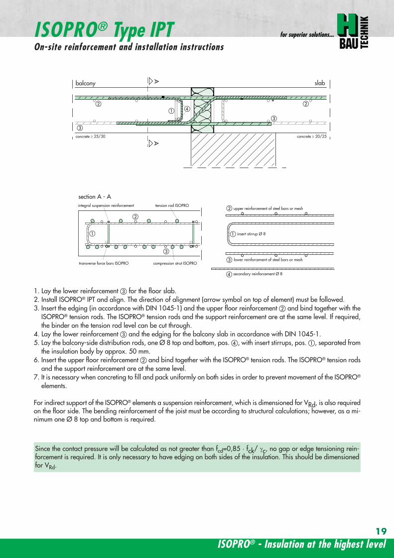
balcony slab
upper reinforcement of steel bars or mesh
lower reinforcement of steel bars or mesh
insert stirrup Oslash 8A
Aa
b
c
a
c
b
section A - A
a
c
b
transverse force bars ISOPRO compression strut ISOPRO
integral suspension reinforcement tension rod ISOPRO
d
d
b
c
concrete concrete
secondary reinforcement Oslash 8
1 Lay the lower reinforcement for the floor slab2 Install ISOPROreg IPT and align The direction of alignment (arrow symbol on top of element) must be followed3 Insert the edging (in accordance with DIN 1045-1) and the upper floor reinforcement and bind together with the
ISOPROreg tension rods The ISOPROreg tension rods and the support reinforcement are at the same level If requiredthe binder on the tension rod level can be cut through
4 Lay the lower reinforcement and the edging for the balcony slab in accordance with DIN 1045-15 Lay the balcony-side distribution rods one Oslash 8 top and bottom pos with insert stirrups pos separated from
the insulation body by approx 50 mm6 Insert the upper floor reinforcement and bind together with the ISOPROreg tension rods The ISOPROreg tension rods
and the support reinforcement are at the same level7 It is necessary when concreting to fill and pack uniformly on both sides in order to prevent movement of the ISOPROreg
elements
For indirect support of the ISOPROreg elements a suspension reinforcement which is dimensioned for VRd is also requiredon the floor side The bending reinforcement of the joist must be according to structural calculations however as a mi-nimum one Oslash 8 top and bottom is required
Since the contact pressure will be calculated as not greater than fcd=085 middot fck γc no gap or edge tensioning rein-forcement is required It is only necessary to have edging on both sides of the insulation This should be dimensionedfor VRd
ISOPROreg - Insulation at the highest level
ISOPROreg Type IPTOn-site reinforcement and installation instructions
for superior solutions
19
ISOPROreg Type IPOn-site reinforcement and installation instructions
balcony
slab
wall
balcony
h lt
80
ab
c
a
b
c
aa
a
a
b
c
b
c
a
a
bb
a
c
c
ee
d
d
b
b
upper reinforcement of steel bars or mesh
lower reinforcement of steel bars or mesh
closed stirrup
inse
rt s
tirru
p
reinforcement
upper reinforcement of steel bars or mesh
lower reinforcement of steel bars or mesh
closed stirrup
upper reinforcement of steel bars or mesh
lower reinforcement of steel bars or mesh
clos
ed s
tirru
p
insert stirrup
parallel reinforcement
ain
sert
stir
rup
b
reinforcementb
wall
balcony wall
balcony
slab
balcony
slab
ndash If the height offset is less than 80 mm a standardelement can also be used
ndash In this case a stirrup reinforcement with an upper leglength gt ls is required to deflect the tensile force onthe floor side
ndash Dimensioning the stirrup reinforcement for the can-tilever effects and transverse forces from the balcony
slabndash For connection reinforcement on the balcony side see
page 1819ndash The necessary transverse reinforcement in the overlap
area must be proved in accordance with DIN 1045-1ndash Recommended joist width at least 200 mm
Connection to a ldquomarginallyrdquo height-offset floor slab
balcony
slab
wall
balcony
h lt
80
ab
c
a
b
c
a
a
a
a
b
c
b
c
a
a
bb
a
c
c
ee
d
d
b
b
upper reinforcement of steel bars or mesh
lower reinforcement of steel bars or mesh
closed stirrup
inse
rt s
tirru
p
reinforcement
upper reinforcement of steel bars or mesh
lower reinforcement of steel bars or mesh
closed stirrup
upper reinforcement of steel bars or mesh
lower reinforcement of steel bars or mesh
clos
ed s
tirru
p
insert stirrup
parallel reinforcement
ain
sert
stir
rup
b
reinforcementb
wall
balcony wall
balcony
slab
balcony
slab
ndash The ISOPROreg tension rods comply with the necessaryoverlap length ls given in DIN 1045-1
ndash For connection reinforcement on the balcony side seepage 1819
ndash The necessary transverse reinforcement in the overlaparea must be proved in accordance with DIN 1045-1
ndash The minimum wall thickness is dependent on the type
Connection to a vertical wall ndash connection downwards
balcony
slab
wall
balcony
h lt
80
ab
c
a
b
c
a
a
a
a
b
c
b
c
a
a
bb
a
c
c
ee
d
d
b
b
upper reinforcement of steel bars or mesh
lower reinforcement of steel bars or mesh
closed stirrup
inse
rt s
tirru
p
reinforcement
upper reinforcement of steel bars or mesh
lower reinforcement of steel bars or mesh
closed stirrup
upper reinforcement of steel bars or mesh
lower reinforcement of steel bars or mesh
clos
ed s
tirru
p
insert stirrup
parallel reinforcement
ain
sert
stir
rup
b
reinforcementb
wall
balcony wall
balcony
slab
balcony
slab
ndash The ISOPROreg tension rods comply with the necessaryoverlap length ls given in DIN 1045-1
ndash For connection reinforcement on the balcony side seepage 1819
ndash The necessary transverse reinforcement in the overlaparea must be proved in accordance with DIN 1045-1
ndash The minimum wall thickness is dependent on the type
Connection to a vertical wall ndash connection upwards
wwwh-baucom20
ISOPROreg
Special types Valid for type series IP and IPT (analogously)
balcony
slab
wall
balcony
h lt
80
ab
c
a
b
c
a
a
a
a
b
c
b
c
a
a
bb
a
c
c
ee
d
d
b
b
upper reinforcement of steel bars or mesh
lower reinforcement of steel bars or mesh
closed stirrup
inse
rt s
tirru
p
reinforcement
upper reinforcement of steel bars or mesh
lower reinforcement of steel bars or mesh
closed stirrup
upper reinforcement of steel bars or mesh
lower reinforcement of steel bars or mesh
clos
ed s
tirru
p
insert stirrup
parallel reinforcement
ain
sert
stir
rup
b
reinforcementb
wall
balcony wall
balcony
slab
balcony
slab
ndash dimensioning of the stirrup reinforcement for can-tilever effect and transverse force on the balcony slab
ndash the ISOPROreg tension rods comply with the DIN 1045-1 requirement for overlap length ls
ndash for on-site reinforcement see pages 1819
ndash the required transverse reinforcement in the overlapzone must be proven in compliance with DIN 1045-1
ndash recommended step-down width at least 220 mm
Connection to a floor slab with a step-up offset
balcony
slab
wall
balcony
h lt
80
ab
c
a
b
c
a
a
a
a
b
c
b
c
a
a
bb
a
c
c
ee
d
d
b
b
upper reinforcement of steel bars or mesh
lower reinforcement of steel bars or mesh
closed stirrup
inse
rt s
tirru
p
reinforcement
upper reinforcement of steel bars or mesh
lower reinforcement of steel bars or mesh
closed stirrup
upper reinforcement of steel bars or mesh
lower reinforcement of steel bars or mesh
clos
ed s
tirru
p
insert stirrup
parallel reinforcementa
inse
rt s
tirru
p
b
reinforcementb
wall
balcony wall
balcony
slab
balcony
slab
ndash dimensioning of the stirrup reinforcement for can-tilever effect and transverse force on the balcony slab
ndash the ISOPROreg tension rods comply with the DIN 1045-1 requirement for overlap length ls
ndash for on-site reinforcement see pages 1819
ndash the required transverse reinforcement in the overlapzone must be proven in compliance with DIN 1045-1
ndash constructive angle reinforcement pos 3ndash recommended step-down width at least 220 mm
Connection to a floor slab with step-down offset
ISOPROreg - Insulation at the highest level
for superior solutions
21
ISOPROreg
Special types Valid for type series IP and IPT (analogously)
After stripping freely-protruding concrete slabs experience a lowering of the slab edge This displacement is a com-bination of the deformation of the balcony insulation elements used and the bending of the slab itself These two de-formations are superimposed and compensated by raising the formworkThe calculations shown below give the required formwork height offset at the end of the cantilever which results fromthe ISOPROreg elements at 100 loading For the total height offset the slab deformation should be added in accor-dance with DIN 1045-1 The total height offset defined in the construction plans from the structural design engineershould take into account the planned direction of the drainage when rounding off the results
wwwh-baucom22
ISOPROreg
Deflection and height offset
Element height h [mm] IP 88IP 107IP 108
IP 127IP 128IP 129
IP 1210
IPT 1211IPT 1212IPT 1412
IPT 1414Concrete covering cv
30 35 40 45 50160 051 059 092 106
160 048 056 087 100160 170 045 053 082 094
160 170 043 050 077 089160 170 180 041 047 073 084
170 180 039 045 070 080170 180 190 037 043 067 079
180 190 035 041 064 073180 190 200 034 039 061 069
190 200 033 038 059 067190 200 210 031 036 056 064
200 210 030 035 054 062200 210 220 029 034 052 059
210 220 028 033 050 057210 220 230 027 031 049 055
220 230 026 030 047 053220 230 240 026 029 046 052
230 240 025 029 044 050230 240 250 024 028 043 049
240 250 023 027 042 047240 250 023 026 040 046
250 022 025 039 045250 021 025 038 043
Offset height of the balcony slab
ISOPROreg - Insulation at the highest level
for superior solutionsISOPROreg
Deflection and height offset
Example for defining the balcony slab height offset
mEd bending moment used to determine the height offset resulting from the ISOPROreg elementThe definitive load combination is decided by the structural engineer
mRd design moment of the ISOPROreg element taken from the dimensioning table on pages 16 and 17lk Cantilever length in [m]
ExampleCantilever length lk = 180 mSlab thickness h = 180 mmIntrinsic weight (slab and covering) g = 60 kNm2
Edge load (parapet) F = 15 kNmLive load p = 40 kNm2
Concrete covering cv = 30 mm
Design calculationsmEd= (g + p) x lk2 2 + F x lk = (60 middot 135 + 40 middot 15) middot 182 2 + 15 middot 18 middot 135 = 265 kNmmvEd = (g + p) x lk + F = (60 middot 135 + 40 middot 15) middot 18 + 15 middot 135 = 274 kNm
Selected ISOPROreg IP 127 cv 30 h = 180 mm mRd = 289 kNmm vRd = 415 kNm
Selected load combination for determination of the height offset resulting from the ISOPROreg element mEd= (g + p3) middot lk22 + F middot lk= (60 middot 135 + 403 middot 15) middot 182 2 + 15 middot 18 middot 135 =200 kNmm
uuml = 041 middot (265 289) middot 180 middot 10 = 67 mm
23
uuml [mm] = value from table middot (mEdmRd) middot lk [m] middot 10
wwwh-baucom24
The external concrete components must have expansion joints at right angles to the insulation layer in order to limitthe stress caused by changes in temperature The spacing of the joints e is given in the following table
balcony
ISOPRO ISOPRO
expansion joint
balcony
e 2
e 2
ISOPRO Type IPT Corner
expansion joint
seperation ofexpansion joints e
seperation ofexpansion joints e
expansion jointExpansion joint spacing for ISOPROreg Types IP und IPT
Rod diameter [mm] le 10 12 14 16 20
Joint spacing e [m] 130 113 101 92 80
balcony
ISOPRO ISOPRO
expansion joint
balcony
e 2
e 2
ISOPRO Type IPT Corner
expansion joint
seperation ofexpansion joints e
seperation ofexpansion joints e
expansion joint
expansion joint dowellingeg HED-S + plastic sleeves
ISOPROreg
Expansion joint spacing
For corner constructions the maximum rod leg length is e2
ISOPROreg - Insulation at the highest level
for superior solutions
25
a a
b
c
b
c
sup3100
In pre-cast units
Arrange the lower reinforcement layer including themesh support as per structural design Distance to in-sulation joint le 100 mm (applies to IP only)
Install lower section The last transverse rod in themesh must be placed as close as possible to the insula-tion observing the required concrete covering
For IP the transverse force rod can be under or on topof the mesh The mesh support should be lifted until itis underneath the tension reinforcement
Concrete the slab element
Locate and fix the associated upper section andwhere required intermediate section
Type IP is supplied with suspension reinforcement asstandard
On-site
Lay the necessary on-site reinforcement on the floorside
Lay the slab element on the pre-prepared timberbeams
Lay the necessary on-site reinforcement on the bal-cony side
Attach the associated upper section and where re-quired intermediate section Bind the tension strutto the on-site reinforcement
h = 210 to 250 mm
Important note fit additional insertion stirrups Oslash 620 or stirrup meshQ188A on the balcony side
In type IP pre-cast units In type IPT pre-cast units
a a
b
c
b
c
sup3100
Type IP on-site Type IPT on-site
Important noteThe type identification for lower and upper sections must match (see also colour identification) The direction of in-stallation (on the balcony side) is mandatory
ISOPROreg
Two-part elements
wwwh-baucom26
upper section
centre section
lower section
upper section
centre section
lower section
balcony balconyslab slab
Type IP Type IPT
Construction
All ISOPROreg elements of types IP and IPT can be supplied as two-part elements
General notes
ndash The permitted resultant stresses can be found in thetables on pages 16 and 17 of this technical information
ndash Intermediate sections can be supplied for height offsetcompensation in 20 and 40 mm thicknesses
ndash Type IP If the mesh supports are placed with a spacingof le 100 mm from the insulation joint no additionalsuspension reinforcement is required Instead asuspension reinforcement dimensioned for VRd shouldbe located along the insulation joints
ndash For information regarding the required formwork height off-set and the maximum spacing of expansion joints refer topages 22 23 and 24
ndash The adhesive labels (type designation) for the upper andlower sections must be identical Follow the instructions forthe balcony side and the floor side
The following elements also have an addi-tional colour coding
ISOPROreg Type Colour code
IP 107 greenIP 127 blueIP 128 yellowIP 1210 white
The continuity of the colour coding throughthe elements ensures correct matching everytime even for short sections
ISOPROreg
Two-part elements
ISOPROreg - Insulation at the highest level
for superior solutions
27
balcony sidebalcony side
section 1st position
section 2nd position
slab balcony
1st position
2nd
posi
tion
cv
cvslab balcony
slab balcony
section 1st position
section 2nd position
1st position
2nd
posi
tion
slab balcony
IPT 127 Corner 820mmIPT 1210 Corner 960mm
IPT 127 Corner 820mmIPT 1210 Corner 960mm
IPT
127
Cor
ner
820m
mIP
T 12
10
Cor
ner
960m
mIP
T 12
7 C
orne
r82
0mm
IPT
121
0 C
orne
r96
0mm
General notes
Area of application for type IPT-Corner from slab thickness h le 180 mmOn-site reinforcement using overlap joints in accordance with DIN 1045-12001-07 Section 126Please refer to the information regarding on-site reinforcement on page 29Special elements for h = 160 mm are possibleBecause of the compression level a minimum spacing of the floor-side filigree slabs from the insulation body of185 mm is required for the ISOPROreg IPT-Corner elements
Type Length of element [m] Tension rods Compression level Transverse force rods
IPT 107-Corner 050 + 050 5 Oslash 10 + 5 Oslash 10 2 x 4 compression block 2 Oslash 10 + 2 Oslash 10
IPT 127-Corner 062 + 062 6 Oslash 12 + 6 Oslash 12 12 Oslash 14 + 12 Oslash 14 3 Oslash 10 + 3 Oslash 10
IPT 1210-Corner 062 + 062 6 Oslash 14 + 6 Oslash 14 14 Oslash 14 + 14 Oslash 14 3 Oslash 12 + 3 Oslash 12
Configuration of the elements
IPT 107-Corner
ISOPROreg Type IPT EckConstruction and dimensions
wwwh-baucom28
Plate thickness [mm] referred to cv [mm] Dimensional values for acceptable load moments MRd [kNm]
30 35 IPT 107 Corner IPT 127 Corner IPT 1210 Corner- 180 169 277 320
180 - 178 292 337- 190 186 306 354
190 - 195 320 370- 200 203 335 387
200 - 212 349 404- 210 220 363 421
210 - 229 378 437- 220 237 392 454
220 - 246 406 471- 230 254 421 487
230 - 263 435 504- 240 271 449 521
240 - 280 463 537- 250 289 478 554
250 - 297 492 571Dimensional values for acceptable transverse forces VRd [kN]
h = 180 - 250 [mm] 483 724 1043
balcony sidebalcony side
section 1st position
section 2nd position
slab balcony
1st position
2nd
posi
tion
cv
cvslab balcony
slab balcony
section 1st position
section 2nd position
1st position
2nd
posi
tion
slab balcony
IPT 127 Corner 820mmIPT 1210 Corner 960mm
IPT 127 Corner 820mmIPT 1210 Corner 960mm
IPT
127
Cor
ner
820m
mIP
T 12
10
Cor
ner
960m
mIP
T 12
7 C
orne
r82
0mm
IPT
121
0 C
orne
r96
0mm
Dimensioning table for concrete gege C2025
IPT 127-CornerIPT 1210-Corner
ISOPROreg Type IPT CornerConstruction and dimensions
ISOPROreg - Insulation at the highest level
for superior solutions
29
1st position
2nd
posi
tion
balcony slab
a
da
b b
c c
dstarter bar 1st position supplementary reinforcement
supplementary reinforcement
supp
lem
enta
ry r
einf
orce
men
t
supp
lem
enta
ry r
einf
orce
men
t
starter bar 1st position
stra
ter
bar
2nd
posi
tion
star
ter
bar
2nd
posi
tion
Type IPT 107-Corner IPT 127-Corner IPT 1210-Corner
starter bar 1st position 5 Oslash 10 6 Oslash 12 6 Oslash 14
starter bar 2nd position 5 Oslash 10 6 Oslash 12 6 Oslash 14
Supplementaryreinforcement 5 Oslash 10 6 Oslash 12 6 Oslash 14
Supplementaryreinforcement 5 Oslash 10 6 Oslash 12 6 Oslash 14
extension of the tension reinforcement internally as well as externally length = 2 x balcony cantilever length
ISOPROreg Type IPT CornerOn-site reinforcement
wwwh-baucom30
ISOPROreg - Insulation at the highest level
for superior solutions
IPQ IPQIPH
IPH
IPH
IPH
IPQS IPQSIPH IPQQS IPQQSIPH
IPQ IPQ
IPQ
IPQQ IPQQ
IPQQ IPQQIP
QS
IPQ IPQ
IPQ
Z
IPQ
S tie rod inlower position
IPQQ IPQQ
IPQ
Z
IPQ
S tie rod inlower position
propped balcony
internal-corner balcony with props
ISOPROreg
Examples of transverse force elements
propped balcony
propped balcony with selective point connection
internal-corner balcony with props
inset balcony with tieback3-sided overlying loggia with tieback
propped balcony with selective point connection
31
wwwh-baucom32
1000
1000
balcony slab balcony slab
IPQ 86 495 mmIPQ 88 495 mmIPQ 106 615 mmIPQ 126 740 mm
IPQ 86 495 mmIPQ 88 495 mmIPQ 106 615 mmIPQ 126 740 mm80
370 80 150
Calculated values for acceptable transverse forces vRd [kNm]
Element height IPQ 64 IPQ 65 IPQ 66 IPQ 68 IPQ 610
160 - 250 mm 348 435 522 695 869
Type IPQ 64 IPQ 65 IPQ 66 IPQ 68 IPQ 610Length [mm] 1000 1000 1000 1000 1000
Transverse force rods 4 Oslash 6 5 Oslash 6 6 Oslash 6 8 Oslash 6 10 Oslash 6
Compression blocks 4 4 4 4 4needed As [cmsup2] 08 10 12 16 20
Dimensioning table - Type IPQ for concrete gege C2025
Configuration of the elements Type IPQ
section
Top view
ISOPROreg Type IPQConstruction and dimensions
IPQ 64 - 610
min Element hight depentend on rod diameter Oslash 10 h ge170 Oslash 12 h ge180 Oslash 14 h ge190
ISOPROreg - Insulation at the highest level
for superior solutions
33
balcony slab
upper reinforcement of steel bars or mesh
lower reinforcement of steel bars or mesh
transverse shear force reinforcement 2 Oslash 8
insert stirrup
ls ls
a
b
c
d
d
a
c
d
b
suspension reinforcemente
ed
secondary reinforcement 2 Oslash 8
concrete concrete
The on-site suspension reinforcement pos and should be calculated for VRd (cf type test No 0519) and loca-ted next to the transverse force rods A Oslash 8 mm steel distribution rod should be installed above and below The sus-pension reinforcement can be replaced by a mesh support (see type IP page 18)DIN 1045-1 Section 1033 applies to the proof of the transverse force capacity of the slabs without shear reinforce-ment For proof of the transverse force capacity of the slabs with shear reinforcement DIN 1045-1 Section 1034 ap-plies The maximum transmissible transverse force across the joints must be limited to 03 VRdmax zu begrenzen
ISOPROreg Type IPQOn-site reinforcement
Calculated values for acceptable transverse forces vRd [kNm]
Element height IPQ 86 IPQ 88 IPQ 106 IPQ 125 IPQ 126
160 - 250 mm 927 1236 1449 1739 2089
Type IPQ 86 IPQ 88 IPQ 106 IPQ 125 IPQ 126Length [mm] 1000 1000 1000 1000 1000
Transverse force rods 6 Oslash 8 8 Oslash 8 6 Oslash 10 5 Oslash 12 6 Oslash 12
Compression blocks 4 4 4 4 4needed As [cmsup2] 21 28 33 40 48
Configuration of the elements Type IPQ
min Element hight depentend on rod diameter Oslash 10 h ge170 Oslash 12 h ge180 Oslash 14 h ge190
wwwh-baucom34
ISOPROreg Type IPQS 2Construction and dimensions
balcony slab
balcony slab
Calculated values for acceptable transverse forces VRd [kN]
Element height IPQS 62 IPQS 82 IPQS 102 IPQS 122 IPQS 142
160 - 250 mm 174 309 483 695 947
Dimensioning table - Type IPQS2 for concrete gege C2025
Type IPQS 62 IPQS 82 IPQS 102 IPQS 122 IPQS 142
Element length [mm] 300 300 300 300 300
Transverse force rods 2 Oslash 6 2 Oslash 8 2 Oslash 10 2 Oslash 12 2 Oslash 14
Compression rods 2 Oslash 10 2 Oslash 10 3 Oslash 10 4 Oslash 12 4 Oslash 14needed As [cmsup2] 040 071 111 160 218
Configuration of the elements Type IPQS2
min Element height dependent on rod diameter Oslash 10 h ge170 Oslash 12 h ge180 Oslash 14 h ge190
IPQS 82 495mmIPQS102 615mmIPQS122 740mmIPQS 142 860mm
IPQS 62
IPQS 82 495mmIPQS102 615mmIPQS122 740mmIPQS 142 860mm
ISOPROreg - Insulation at the highest level
for superior solutions
35
Calculated values for acceptable transverse forces VRd [kN]
Element height IPQS 63 IPQS 83 IPQS 103 IPQS 123 IPQS 143
160 - 250 mm 261 464 724 1043 1420
Dimensioning table - Type IPQS3 for concrete gege C2025
Type IPQS 63 IPQS 83 IPQS 103 IPQS 123 IPQS 143
Element length [mm] 400 400 400 400 400
Transverse force rods 3 Oslash 6 3 Oslash 8 3 Oslash 10 3 Oslash 12 3 Oslash 14
Compression rods 2 Oslash 10 3 Oslash 10 4 Oslash 12 5 Oslash 12 6 Oslash 14needed As [cmsup2] 060 107 167 240 327
Configuration of the elements Type IPQS3
balcony slab
balcony slab
ISOPROreg Type IPQS 3Construction and dimensionsn
IPQS 83 495mmIPQS103 615mmIPQS123 740mmIPQS 143 860mm
IPQS 63
IPQS 83 495mmIPQS103 615mmIPQS123 740mmIPQS 143 860mm
min Element height dependent on rod diameter Oslash 10 h ge170 Oslash 12 h ge180 Oslash 14 h ge190
wwwh-baucom36
ISOPROreg Type IPQQConstruction and dimensions
1000
1000
balcony balconyslab slab
180 80 150 80165 165
370 80 80150
IPQQ 86 495 mmIPQQ 106 615 mmIPQQ 126 740 mm
IPQQ 86 495 mmIPQQ 106 615 mmIPQQ 126 740 mm
IPQQ 64 IPQQ 66IPQQ 68 IPQQ 610
Calculated values for acceptable transverse forces vRd [kNm]
Element height IPQQ 64 IPQQ 66 IPQQ 68 IPQQ 610 IPQQ 86 IPQQ 106 IPQQ 126
160 - 250 mm plusmn348 plusmn522 plusmn695 plusmn869 plusmn927 plusmn1449 plusmn2086
Type IPQQ 64 IPQQ 66 IPQQ 68 IPQQ 610 IPQQ 86 IPQQ 106 IPQQ 126Element length [mm] 500 + 500 500 + 500 500 + 500 500 + 500 500 + 500 500 + 500 500 + 500Transverse force rods 2x4 Oslash 6 2x6 Oslash 6 2x8 Oslash 6 2x10 Oslash 6 2x6 Oslash 8 2x6 Oslash 10 2x6 Oslash 12
Compression rods 4 Oslash 10 4 Oslash 10 6 Oslash 10 6 Oslash 10 6 Oslash 10 10 Oslash 10 10 Oslash 12needed As [cmsup2] 080 120 160 200 213 333 480
Dimensioning table - Type IPQQ for concrete gege C2025
Configuration of the elements Typ IPQQ
Top view
Section
min Element height dependent on rod diameter Oslash 10 h ge170 Oslash 12 h ge180 Oslash 14 h ge190
ISOPROreg - Insulation at the highest level
for superior solutions
37
ISOPROreg Type IPQQOn-site reinforcement
balcony slab
upper reinforcement of steel bars or mesh
lower reinforcement of steel bars or mesh
ls ls
b
c
a
c
d
b
insert stirrupa
d
dinsert stirrupa
ad
d
secondary reinforcement 2 Oslash 8
concrete concrete
secondary reinforcement 2 Oslash 8
The on-site suspension reinforcement pos should be calculated for VRd and located next to the transverse forcerods A Oslash 8 mm steel distribution rod should be installed above and below DIN 1045-1 Section 1033 applies to the proof of the transverse force capacity of the slabs without shear reinforce-ment For proof of the transverse force capacity of the slabs with shear reinforcement DIN 1045-1 Section 1034 ap-plies The maximum transmissible transverse force across the joints must be limited to 03 VRdmax
wwwh-baucom38
ISOPROreg Type IPQQS 2Construction and dimensions
balcony slab
balcony slab
Calculated values for acceptable transverse forces VRd [kN]
Element height IPQQS 62 IPQQS 82 IPQQS 102 IPQQS 122 IPQQS 142
160 - 250 mm plusmn174 plusmn309 plusmn483 plusmn695 plusmn947
Dimensioning table - Type IPQQS2 for concrete gege C2025
Type IPQQS 62 IPQQS 82 IPQQS 102 IPQQS 122 IPQQS 142
Element length [mm] 300 300 300 300 300
Transverse force rods 2x 2 Oslash 6 2x 2 Oslash 8 2x 2 Oslash 10 2x 2 Oslash 12 2x 2 Oslash 14
Compression rods 2 Oslash 10 2 Oslash 10 3 Oslash 10 4 Oslash 12 4 Oslash 14needed As [cmsup2] 040 071 111 160 218
Configuration of the elements Type IPQQS2
IPQQS 82 495mmIPQQS 102 615mmIPQQS 122 740mmIPQQS 142 860mm
IPQQS 62
IPQQS 82 495mmIPQQS 102 615mmIPQQS 122 740mmIPQQS 142 860mm
min Element height dependent on rod diameter Oslash 10 h ge170 Oslash 12 h ge180 Oslash 14 h ge190
ISOPROreg - Insulation at the highest level
for superior solutions
39
ISOPROreg Type IPQQS 3Construction and dimensions
balcony slab
balcony slab
Calculated values for acceptable transverse forces VRd [kN]
Element height IPQQS 63 IPQQS 83 IPQQS 103 IPQQS 123 IPQQS 143
160 - 250 mm plusmn261 plusmn464 plusmn724 plusmn1043 plusmn1420
Dimensioning table - Type IPQQS3 for concrete gege C2025
Type IPQQS 63 IPQQS 83 IPQQS 103 IPQQS 123 IPQQS 143
Element length [mm] 400 400 400 400 400
Transverse force rods 2x 3 Oslash 6 2x 3 Oslash 8 2x 3 Oslash 10 2x 3 Oslash 12 2x 3 Oslash 14
Compression rods 2 Oslash 10 3 Oslash 10 4 Oslash 12 5 Oslash 12 6 Oslash 14needed As [cmsup2] 060 107 167 240 327
Configuration of the elements Type IPQQS3
min Element height dependent on rod diameter Oslash 10 h ge170 Oslash 12 h ge180 Oslash 14 h ge190 alternatively in Element length 500 mm available
IPQQS 83 495mmIPQQS 103 615mmIPQQS 123 740mmIPQQS 143 860mm
IPQQS 63
IPQQS 83 495mmIPQQS 103 615mmIPQQS 123 740mmIPQQS 143 860mm
wwwh-baucom40
ISOPROreg Type IPTDConstruction and dimensions
IPTD IPTD
inset balcony
30
balcony slab
Top view
Section
Example
Table of Dimensions ndash Type IPTD [length in mm]
TypeTension rod Transverse force rod Compression rod Supplemental transverse force
ZL QL DL Q10L Q12LIPTD 126 820 497 820 617 742IPTD 127 820 497 820 617 742IPTD 1210 820 497 820 617 742IPTD 1212 820 497 820 617 742IPTD 1410 960 497 960 617 742
ISOPROreg - Insulation at the highest level
for superior solutions
41
ISOPROreg Type IPTDOn-site reinforcement
balcony slab
upper reinforcement of steelbars or mesh
lower reinforcement of steelbars or mesh
secondary reinforcement 2 Oslash 8
secondary reinforcement 2 Oslash 8
insert stirrup
ls ls
AA
a
b
c
d
d
a
c
d
b
lower reinforcement of steelbars or meshc
upper reinforcement of steelbars or meshb
d
insert stirrupee
b
c
a
a
Section A - A
ISOPRO transverse force rods ISOPRO compression rods
ISOPRO transverse force rods ISOPRO tension rods
d
concrete concrete
The on-site suspension reinforcement pos should be calculated for VRd and located next to the transverse forcerods A Oslash 8 mm steel distribution rod should be installed above and below DIN 1045-1 Section 1033 applies to the proof of the transverse force capacity of the slabs without shear reinforce-ment For proof of the transverse force capacity of the slabs with shear reinforcement DIN 1045-1 Section 1034 ap-plies The maximum transmissible transverse force across the joints must be limited to 03 VRdmax
wwwh-baucom42
ISOPROreg Type IPTDDimensioning table for concrete gege C2025
Plate thickness [mm] withreference to cv [mm] Rated values for moment loading mRd [kNmm]
30 35 IPTD 126IPTD 126
Q10IPTD 126
Q12IPTD 127
IPTD 127Q10
IPTD 127Q12
IPTD 1210
- 160 plusmn 145 - - plusmn 182 - - plusmn 253160 - plusmn 154 - - plusmn 193 - - plusmn 269- 170 plusmn 162 plusmn 146 - plusmn 204 plusmn 187 - plusmn 284
170 - plusmn 171 plusmn 154 - plusmn 214 plusmn 197 - plusmn 299- 180 plusmn 180 plusmn 162 plusmn 145 plusmn 225 plusmn 208 plusmn 190 plusmn 314
180 - plusmn 189 plusmn 170 plusmn 152 plusmn 236 plusmn 218 plusmn 199 plusmn 330- 190 plusmn 197 plusmn 178 plusmn 159 plusmn 247 plusmn 228 plusmn 209 plusmn 345
190 - plusmn 206 plusmn 186 plusmn 166 plusmn 258 plusmn 238 plusmn 218 plusmn 360- 200 plusmn 215 plusmn 194 plusmn 173 plusmn 269 plusmn 248 plusmn 227 plusmn 375
200 - plusmn 223 plusmn 202 plusmn 180 plusmn 280 plusmn 258 plusmn 236 plusmn 391- 210 plusmn 232 plusmn 209 plusmn 187 plusmn 291 plusmn 268 plusmn 246 plusmn 406
210 - plusmn 241 plusmn 217 plusmn 194 plusmn 302 plusmn 278 plusmn 255 plusmn 421- 220 plusmn 250 plusmn 225 plusmn 201 plusmn 313 plusmn 288 plusmn 264 plusmn 437
220 - plusmn 258 plusmn 233 plusmn 208 plusmn 324 plusmn 298 plusmn 273 plusmn 452- 230 plusmn 267 plusmn 241 plusmn 215 plusmn 335 plusmn 308 plusmn 283 plusmn 467
230 - plusmn 276 plusmn 249 plusmn 222 plusmn 346 plusmn 318 plusmn 292 plusmn 482- 240 plusmn 285 plusmn 257 plusmn 229 plusmn 357 plusmn 328 plusmn 301 plusmn 498
240 - plusmn 293 plusmn 265 plusmn 236 plusmn 368 plusmn 339 plusmn 310 plusmn 513- 250 plusmn 302 plusmn 272 plusmn 243 plusmn 379 plusmn 349 plusmn 320 plusmn 528
250 - plusmn 311 plusmn 280 plusmn 250 plusmn 390 plusmn 359 plusmn 329 plusmn 543
Rated values for transverse force loading vRd [kNm]
h = 160 - 250 [mm ] plusmn 415 plusmn 762 plusmn 1098 plusmn 415 plusmn 762 plusmn 1098 plusmn 415
Type IPTD 126 IPTD 126Q10
IPTD 126Q12
IPTD 127 IPTD 127Q10
IPTD 127Q12
IPTD 1210
Element lenght [mm] 500 + 500 500 + 500 500 + 500 500 + 500 500 + 500 500 + 500 500 + 500
Tension rods 6 Oslash 12 6 Oslash 12 6 Oslash 122 Oslash 10 + 6 Oslash 12
2 Oslash 10 + 6 Oslash 12
2 Oslash 10 +6 Oslash 12
10 Oslash 12
Transverse forcerods
2x4 Oslash 8 2x4 Oslash 10 2x4 Oslash 12 2x4 Oslash 8 2x4 Oslash 10 2x4 Oslash 12 2x4 Oslash 8
Compression rods 6 Oslash 12 6 Oslash 12 6 Oslash 122 Oslash 10 + 6 Oslash 12
2 Oslash 10 +6 Oslash 12
2 Oslash 10 +6 Oslash 12
10 Oslash 12
Configuration of the elements Type IPTD
ISOPROreg - Insulation at the highest level
for superior solutions
43
ISOPROreg Type IPTDDimensioning table for concrete gege C2025
Rated values for moment loading mRd [kNmm]
IPTD 1210Q10
IPTD 1210Q12
IPTD 1212IPTD 1212
Q10IPTD 1212
Q12IPTD 1410
IPTD 1410Q10
IPTD 1410Q12
- - plusmn 307 - - plusmn 349 - -- - plusmn 326 - - plusmn 371 - -
plusmn 268 - plusmn 345 plusmn 328 - plusmn 392 plusmn 377 -plusmn 282 - plusmn 363 plusmn 346 - plusmn 414 plusmn 397 -plusmn 297 plusmn 279 plusmn 382 plusmn 364 plusmn 346 plusmn 436 plusmn 418 plusmn 401plusmn 311 plusmn 293 plusmn 400 plusmn 381 plusmn 363 plusmn- 457 plusmn 439 plusmn 421plusmn 325 plusmn 306 plusmn 419 plusmn 399 plusmn 380 plusmn 479 plusmn 459 plusmn 441plusmn 340 plusmn 320 plusmn 437 plusmn 417 plusmn 397 plusmn 500 plusmn 480 plusmn 461plusmn 354 plusmn 333 plusmn 456 plusmn 434 plusmn 414 plusmn 522 plusmn 501 plusmn 480plusmn 369 plusmn 347 plusmn 474 plusmn 452 plusmn 430 plusmn 543 plusmn 522 plusmn 500plusmn 383 plusmn 361 plusmn 493 plusmn 470 plusmn 447 plusmn 565 plusmn 542 plusmn 520plusmn 397 plusmn 374 plusmn 511 plusmn 487 plusmn 464 plusmn 587 plusmn 563 plusmn 540plusmn 412 plusmn 388 plusmn 530 plusmn 505 plusmn 481 plusmn 608 plusmn 584 plusmn 560plusmn 426 plusmn 401 plusmn 548 plusmn 523 plusmn 498 plusmn 630 plusmn 604 plusmn 580plusmn 440 plusmn 415 plusmn 567 plusmn 540 plusmn 515 plusmn 351 plusmn 625 plusmn 600plusmn 455 plusmn 428 plusmn 585 plusmn 558 plusmn 531 plusmn 673 plusmn 646 plusmn 619plusmn 469 plusmn 442 plusmn 604 plusmn 576 plusmn 548 plusmn 694 plusmn 666 plusmn 639plusmn 484 plusmn 455 plusmn 622 plusmn 593 plusmn 565 plusmn 716 plusmn 687 plusmn 659plusmn 498 plusmn 469 plusmn 641 plusmn 611 plusmn 582 plusmn 737 plusmn 708 plusmn 679plusmn 512 plusmn 483 plusmn 659 plusmn 629 plusmn 599 plusmn 759 plusmn 728 plusmn 699
Rated values for transverse force loading vRd [kNm]
plusmn 762 plusmn 1098 plusmn 415 plusmn 762 plusmn 1098 plusmn 415 plusmn 762 plusmn 1098
IPTD 1210Q10
IPTD 1210Q12
IPTD 1212 IPTD 1212Q10
IPTD 1212Q12
IPTD 1410 IPTD 1410Q10
IPTD 1410Q12
500 + 500 500 + 500 500 + 500 500 + 500 500 + 500 500 + 500 500 + 500 500 + 500
10 Oslash 12 10 Oslash 12 12 Oslash 12 12 Oslash 12 12 Oslash 12 10 Oslash 14 10 Oslash 14 10 Oslash 14
2x4 Oslash 10 2x4 Oslash 12 2x4 Oslash 8 2x4 Oslash 10 2x4 Oslash 12 2x4 Oslash 8 2x4 Oslash 10 2x4 Oslash 12
10 Oslash 12 10 Oslash 12 12 Oslash 12 12 Oslash 12 12 Oslash 12 10 Oslash 14 10 Oslash 14 10 Oslash 14
wwwh-baucom44
ISOPROreg Type IPQZConstruction and dimensions
300
40
0
300
40
0
balcony slab
balcony slab
For restraint-free support with an IPQZ element it should be opposed by an IPQS element Both elements should bereinforced by a tieback which corresponds in diameter and rod count to the IPQS and IPQZAn on-site stirrup reinforcement is required to connect IPQS to the floor
Calculated values for acceptable transverse forces VRd [kN]
Element height IPQZ 62 IPQZ 82 IPQZ 102 IPQZ 122 IPQZ 142
160 - 250 mm 174 309 483 695 947
IPQZ 63 IPQZ 83 IPQZ 103 IPQZ 123 IPQZ 143
160 - 250 mm 261 464 724 1043 1420
Dimensioning table ndash Type IPQZ for concrete ge C2025
Type IPQZ 62 IPQZ 82 IPQZ 102 IPQZ 122 IPQZ 142Element lenght [mm] 300 300 300 300 300
Transverse force rods 2 Oslash 6 2 Oslash 8 2 Oslash 10 2 Oslash 12 2 Oslash 14
Configuration of the elements
Type IPQZ 63 IPQZ 83 IPQZ 103 IPQZ 123 IPQZ 143Element length [mm] 400 400 400 400 400
Transverse force rods 3 Oslash 6 3 Oslash 8 3 Oslash 10 3 Oslash 12 3 Oslash 14
min Element height dependent on rod diameter Oslash 10 h ge170 Oslash 12 h ge180 Oslash 14 h ge190
IPQZ 82 83 495mmIPQZ102 103 615mmIPQZ122 123 740mmIPQZ 142 143 860mm
IPQZ 82 83 495mmIPQZ102 103 615mmIPQZ122 123 740mmIPQZ 142 143 860mm
IPQZ 62 63
ISOPROreg - Insulation at the highest level
for superior solutions
45
ISOPROreg Type IPQZOn-site reinforcement
Type Tieback Insert stirrup for use with
IPQZ 62 2 Oslash 6 1 Oslash 6 IPQS 62
IPQZ 82 2 Oslash 8 1 Oslash 8 IPQS 82
IPQZ 102 2 Oslash 10 1 Oslash 10 IPQS 102
IPQZ 122 2 Oslash 12 2 Oslash 8 IPQS 122
IPQZ 142 2 Oslash 14 2 Oslash 10 IPQS 142
tie roda
b
stirrup for anchering tie rodb
a
slab slabbalcony
Typ IPQZ Typ IPQS
Type Tieback Insert stirrup for use with
IPQZ 63 3 Oslash 6 2 Oslash 6 IPQS 63
IPQZ 83 3 Oslash 8 2 Oslash 8 IPQS 83
IPQZ 103 3 Oslash 10 2 Oslash 10 IPQS 103
IPQZ 123 3 Oslash 12 3 Oslash 8 IPQS 123
IPQZ 143 3 Oslash 14 3 Oslash 10 IPQS 143
wwwh-baucom46
ISOPROreg Type IPHConstruction and dimensions
The ISOPROreg elements type IPH which absorb horizontal forces must only be used with ISOPROreg cantilever slabs ortransverse force connections
The number of IPH elements to be used is defined by the structural engineer whereby the expansion joint spacing mustbe maintained
When using ISOPROreg IPH elements the force absorption of the line connection must be reduced by the ratio of thelength of the IPH elements to the total connection length as a percentage
independent of cvReinforcement Length of
element
HRd
Transverse force Horizontal Transverse force Horizontal
IPH 1 2 x 1 Oslash 8 - 100 mm plusmn 74 kN -IPH 2 - 1 Oslash 10 100 mm - plusmn181 kNIPH 3 2 x 1 Oslash 8 1 Oslash 10 100 mm plusmn 74 kN plusmn 181 kN
Dimensioning table ndash Type IPH for concrete gege C2025
balcony slab
balcony slab
balcony slab
balcony slab
balcony slab
balcony slab
100
100
100
250 80 250
250 80 250
250 80 250IPH 1 for absorption of horizontal forces parallel to the insulation joint
IPH 2 for absorption of horizontal forces perpendicular to the insulation joint
IPH 3 for absorption of horizontal forces parallel and perpendicular to the insulation joint
ISOPROreg - Insulation at the highest level
for superior solutions
47
ISOPROreg Type IPHOn-site reinforcement
The installation of the ISOPROreg IPH elements is analogous to the installation of the ISOPROreg cantilever slabs or trans-verse force connectionsThe number and positions of the elements are defined in the structural detail The elements must be fixed in their posi-tions
plate slab balcony slab
ls ls
lower reinforcement of steel bars or mesh
d
lower reinforcement of steel bars or mesh
upper reinforcement of steel bars or mesh
a
aa
dc
d
insert stirrup
a
b
c
secondary reinforcement Oslash 8
b
c c
insert stirrup
wwwh-baucom48
ISOPROreg Type IPAConstruction and calculation values
29
0204
0608
1012
1416
1820
2422
2628
0204
0608
1012
1416
1820
2224
2628
0 +10 +20 +30 +40 +50-10-20-30-40-50
dimensioning axis
MEd
VEd
NEd
380
60
gt160
sup3 16
0
130
Section
Mathematical model ndash Static system Interaction diagram
NRd [kN]
M Rd[kNm]
DimensionsLength of element 350 mmFascia thickness 160 ndash 240 mmHeight of element from 160 mmThickness of insulation element 60 mm
ReinforcementTension rods 3 Oslash 8Compression rods 3 Oslash 8Transverse force rods 2 x 2 Oslash 6
Calculated values for NRd = 0MRd 29 kNmelementVRd plusmn 127 kNelement
ISOPROreg - Insulation at the highest level
for superior solutions
49
ISOPROreg Type IPAOn-site reinforcement and installation instructions
400
100
aa
bc
b c
dd
e
f
gh
h
e
g
h
f
inse
rt s
tirru
ps
conn
ectio
n re
info
rcem
ent
conn
ectio
n re
info
rcem
ent
steel bar Oslash 8
upper slab reinforcement
insert stirrups 3 Oslash 8 150 mmsupplied
insert stirrup as constructive edging
lower slab reinforcement
34
160
56 59 60 60 59 56
34
Section Plan
Installation instructions1 Lay lower reinforcement including edging
2 Install ISOPROreg elements type IPA Spacing in accordance with static requirements
3 Install positions and and tie together
4 Lay upper floor reinforcement and tie together with the ISOPROreg reinforcement element
5 Concrete the floor slab Ensure safe positioning
6 Attach the on-site insulation between the ISOPROreg elements
7 Lay the fascia reinforcement and including edging and tie together with the ISOPROreg elements
supplied insulation
Type IPAType IPA
350e = separation of elements
gt 80
gt 16
0
Spacing of the elements Spacing of expansion joints
Expansion joint spacing e le 78 mAbove corner e2 le 35 m
The parapet must be verified as being a continuous supporte = spacing of the elements in accordance with static requirements
wwwh-baucom50
+5 +15 +25 +35-5-15-25-35
05
10
15
0
MEd
NEdVEd
MRdVRd
dimensioning axis
ISOPROreg Type IPFConstruction and calculation values
42034
0
60
100
Section
Mathematical model ndash Static system Interaction diagram
DimensionsLength of element 350 mmHeight of element from 160 mmThickness of insulation element 60 mm
ReinforcementTension rods 3 Oslash 6Compression rods 3 Oslash 6Transverse force rods 2 Oslash 6
Calculated values for NRd = 0MRd plusmn 15 kNmelementVRd + 127 kNelement
NRd [kN]
M Rd[kN
m]
VRd = 127 kN
ISOPROreg - Insulation at the highest level
for superior solutions
51
ISOPROreg Type IPFOn-site reinforcement and installation instructions
b
a insert stirrup min Oslash 6 150 mm
upper slab reinforcement
ac
b
e
d
c lower slab reinforcement
est
eel b
ar Oslash
8
d2
inse
rt s
tirru
p m
in Oslash
6
150
mm
3333
56 59 60 60 59 56
160
350
Section
Plan
Installation instructions1 Lay lower reinforcement including edging
2 Install ISOPROreg elements type IPA Spacing in accordance with static requirements
3 Install positions and and tie together
4 Lay upper floor reinforcement and tie together with the ISOPROreg reinforcement element
5 Concrete the floor slab Ensure safe positioning
6 Attach the on-site insulation between the ISOPROreg elements
7 Lay the fascia reinforcement and including edging and tie together with the ISOPROreg elements
350
60
Type IPF Type IPF
e = separation of elements
supplied insulation
parapet
Spacing of the elements
Spacing of expansion joints
Expansion joint spacing e le 78 mAbove corner e2 le 35 m
The parapet must be verified as beinga continuous support e = spacing of the elements in accor-dance with static requirements
wwwh-baucom52
ISOPROreg Type IPOConstruction and calculation values
23 lK
+PRd
+HEd
lK
sliding film
reinforcedconcrete console
soft-fibre panel
sup3 18
0
sup3 150 60
725
130 60 535
350
sliding film
reinforcedconcrete console
soft-fibre panelsup3
180
sup3 150 60
725
130 60 535
350
Section
Plan Mathematical modelStatic system
DimensionsLength of element 350 mmHeight of element from 180 mmThickness of insulation element 60 mm
ReinforcementTension rods 3 Oslash 6Compression rods 3 Oslash 8Transverse force rods 2 Oslash 10
for Hed = 0 PRd plusmn 171 kNmelement max HRd + 184 kNelement
0 2 4 6 8 10 12 14 16 20 22 Horizontal force HEd [kN]
25
15
10
5
0
P Rd[kN] concrete gege C2530
concrete gege C2025
PRd = 23
PRd = 10
HEd
= 18
4
HEd
= 23
1
ISOPROreg - Insulation at the highest level
for superior solutions
53
ISOPROreg Type IPOOn-site reinforcement and installation instructions
slab
a
a
bde
b
c
c upper reinforcement of steel bars or mesh
lower reinforcement of steel bars or mesh
insert stirrupde
long
itudi
nal r
einf
orce
men
t
clos
ed s
tirru
p
concrete
concrete
Section Installation instructions
1 Lay lower reinforcement including edging
2 Install ISOPROreg elements type IPO Spacingin accordance with static requirements
3 Lay upper floor reinforcement and tie to-gether with the ISOPROreg reinforcement ele-ment
4 Attach the on-site insulation between the ISO-PROreg elements
5 Lay the console reinforcement and andtie together with the ISOPROreg elements Thefloor edge beam must be designed as a con-tinuous support
6 As far as practical the console and the floorshould be concreted simultaneously Ensuresecure positioning
reinforced concrete joist
ISOPRO Type IPO ISOPRO Type IPO
supplied insulation
e = separation of elements350
Spacing of the elements Spacing of expansion joints
Expansion joint spacing e le 78 mAbove corner e2 le 35 m
The parapet must be verified as being a continuous support e = spacing of the elements in accordance with static requirements
wwwh-baucom54
ISOPROreg Type IPSConstruction and calculation values
80
5050
80 ZL
balcony slab plate slab
wall
console
tension rod
transverse force bars
compression strut
ZL
QL
QL
DL
80
DL
100100
BSt 500 Nr Wst Nr 14571
BSt 500 Nr Wst Nr 14571
BSt 500 S
BSt 500 S
Section
80
5050
80 ZL
balcony slab plate slab
wall
console
tension rod
transverse force bars
compression strut
ZL
QL
QL
DL
80
DL
100100
BSt 500 Nr Wst Nr 14571
BSt 500 Nr Wst Nr 14571
BSt 500 S
BSt 500 S
Dimensions - Type IPS [length in mm]
Type Tension rod Transverse forcerod
Compressionrod
ZL QL DLIPS 1 690 500 430IPS 2 820 620 500IPS 3 960 745 570IPS 4 1550 865 600
Dimensioning table for concrete gege C2025Element hight 400 mm IPS 1 IPS 2 IPS 3 IPS 4
moment MRd [kNm] 221 294 375 624
transverse forces VRd [kN] 213 333 480 653
Type IPS 1 IPS 2 IPS 3 IPS 4
Element width [mm] 220 220 220 220
Tension rods 3 Oslash 10 3 Oslash 12 3 Oslash 14 4 Oslash 14
Transverse force rods 2 Oslash 8 2 Oslash 10 2 Oslash 12 2 Oslash 14
Compression rods 3 Oslash 12 3 Oslash 14 3 Oslash 16 3 Oslash 20
Other designs and dimensions are available on requestThe bonding area I underlies the determination of the anchoring lengths However if required the reinforcement rods can also be designed for bonding area II
Configuration of the elements
ISOPROreg - Insulation at the highest level
for superior solutions
55
ISOPROreg Type IPSOn-site reinforcement and installation instructions
wall plate reinforcement to structural calculations
tension rod
transverse force bars
compression strut
a
b
c
d
d
a
b
a closed stirrup
edging
c suspension reinforcementconcrete concrete
Installation instructions
1 Lay wall plate reinforcement to meet structural requirements2 Insert ISOPROreg element type IPS and tie together with the wall
reinforcement Transverse reinforcement in overlap zone in accordance with DIN 1045-1
3 Install and tie together beam reinforcement and according to structural calculations Pos edging in accordance withDIN 1045-1 Pos installed as a closed stirrup to avoid shearing
4 When concreting make sure that both sides are uniformly filled and compacted
5 Formwork offset for the beam in accordance with structural calculations
wall plate reinforcement to structural calculations
tension rod
transverse force bars
compression strut
a
b
c
d
d
a
b
a closed stirrup
edging
c suspension reinforcementconcrete concrete
80
b b
plate slab
Type IPS
wal
l pla
te
Type IPS wal
l pla
te
balcony slab
supplied insulation
Configuration of the elements Expansion joint spacing
TypeJoint spacing [m]
e
IPS 1 113
IPS 2 101
IPS 3 92
IPS 4 80
For corner constructions the maximumrod leg length is e2
wwwh-baucom56
ISOPROreg Type IPWConstruction and calculation values
ZL ZL80
420 420
QL QL
DL DL
290290
low
er s
ectio
n12
50ce
ntre
sec
tion
uppe
r se
ctio
n25
0
h =
150
- 3
50
m
80
balcony
balcony slab
slab
exte
rnal
wal
l
inte
rnal
wal
l
horizontal transverse force bars
horizontal transverse force bars
upper section bht in mm150-250 250 80
lower section bht in mm150-250 1250 80
Section
Table of Dimensions Type IPW [length in mm]
Type
Tension rod Transverseforce rod
Compressionrod
ZL QL DLIPW 1 600 423 270IPW 2 790 563 335IPW 3 980 653 410IPW 4 1170 783 470
Element width b = 150 ndash 250 mmElement height h = 150 ndash 350 mInsulation material thickness t = 80 mm
Dimensioning table for concrete gege C2025Calculated values for acceptable moments MRdy [kNm]
Element height [m] IPW 1 IPW 2 IPW 3 IPW 415 ndash 20 537 918 1169 154420 ndash 25 737 1267 1614 2132
gt 25 937 1616 2059 2720Calculated values for acceptable transverse forces [kN]
vRdz [kN] 412 622 1066 1535vRdy [kN] plusmn137 plusmn137 plusmn137 plusmn137
Type IPW 1 IPW 2 IPW 3 IPW 4Element height [m] ge150 ge150 ge150 ge150Tension rods 4 Oslash 6 4 Oslash 8 4 Oslash 10 4 Oslash 12Transverse force rods Qz 6 Oslash 6 6 Oslash 8 6 Oslash 10 6 Oslash 12Transverse force rods Qy 2 x 2 Oslash 6 2 x 2 Oslash 6 2 x 2 Oslash 6 2 x 2 Oslash 6Compression rods 6 Oslash 8 6 Oslash 10 6 Oslash 12 6 Oslash 14
Configuration of the elements
Moment effects from wind loading are absorbed bythe stiffening effect of the balcony slab
MRdz = 0
Bonding area II underlies the determination of theoverlap lengths On request the anchoring lengthscan also be dimensioned for bonding area I Designsand dimensions deviating from the standard ele-ments are available on request
ISOPROreg - Insulation at the highest level
for superior solutions
57
ISOPROreg Type IPWOn-site reinforcement and installation instructions
MRdz
VRdz VRdy
x
z
y
MRdy
Mathematical model ndash Static system
balcony slab
balcony slab
steel
mes
h re
info
rcem
ent
a
steel
mes
h re
info
rcem
ent
b
e connection reinforcementto structural calculations
f
insert stirrupas constructive edging c
c
d steel bar min 2 Oslash 8
concrete sup3 2025
exte
rnal
wal
l
inte
rnal
wal
l
insert stirrupas constructive edging
connection reinforcementto structural calculations
a bc c
d
d
steel bar min 2 Oslash 8
steel bar min 2 Oslash 8
insert stirrupinsert stirrupsteel mesh reinforcement steel mesh reinforcement
80
wall p
late
wall p
late
balcony slab
plate slab
Type IPWsupplied insulation
Type IPW
b b
e e e
Configuration of the elements
Installation instructions
1 Position internal wall reinforcement 2 Attach the constructive edging inter-
nally (insert stirrup)3 Starting at the bottom assemble the in-
dividual ISOPROreg elements type IPWand tie together with the wall reinforce-ment
4 Erect and internally and tie to-gether
5 Position the external wall reinforce-ments and in accordancewith structural design and tie to theISOPROreg elements
6 When concreting pay particular atten-tion to the positional security of the ele-ments It is recommended to fill andcompact both wall plates at the sametime
wwwh-baucom58
ISOPROreg
Approvals and Type testing
Approvals
ISOPRO Type IP Z-157-244ISOPRO Type IPT Z-157-243
Type testing
ISOPRO Type IP Test No 0517ISOPRO Type IPT Test No 0518ISOPRO Type IPQ Test No 0519
ISOPROreg - Insulation at the highest level
for superior solutions
59
ISOPROreg
Tender
___________________________________________________________________________
Scope Application area DIN 276013 Concrete and reinforced concrete Floor constructions
Structural installations__________________________________________________________________________________
ISOPROreg supporting and thermally insulating connection elements
01 supporting the balcony slab using ISOPROreg elements from H-BAU Technik GmbH02 required for installation03 m Type IP cv = mm h = mm04 m Type IPQ cv = mm h = mm05 part Type cv = mm h = mm
Special fabrication according to the following description
06 for thermal separation of the concrete07 for the storey floors pos 08 for the roofing pos 09 for 10 and11 for the balcony slap pos 12 for the loggia slab pos 13 for the cantilever slab pos 14 for the 15 in fire protection construction class F9016 the bonding is made in the reinforcement of pos and pos 17 deliver18 deliver install and bond with the connection reinforcement19 only install and bond with the connection reinforcement delivery provided20 the installation is made in accordance with instructions from
H-BAU Technik GmbHAm Guumlterbahnhof 2079771 Klettgau-ErzingenGermanyTel +49 (0) 77 42 92 15-20Fax +49 (0) 77 42 92 15-90
21 in accordance with the detail and reinforcement drawings no 22 material 23 wages 24 unit price
25 total price
wwwh-baucom60
NOTES
ISOPROreg - Insulation at the highest level
for superior solutions
61
NOTES
wwwh-baucom
Concreting with system
ISOPROreg
KESIIRAPIDOBATreg
JSDHEDFERBOXreg
BOXFERreg
GRIPRIPreg
PENTAFLEXreg
RIPINOXreg
WARMBORDreg
SCHALBORDreg
ZEMBORDreg
SCHALL-ISO ACCESSORIES
H-BAU Technik GmbHAm Guumlterbahnhof 20D-79771 Klettgau-ErzingenTel + 49 (0) 7742 92 15-20Fax + 49 (0) 7742 92 15-90infoklettgauh-baude
Produktion Nord-OstBrandenburger StraszligeD-14641 WachowTel + 49 (0) 3 3239 775-20Fax + 49 (0) 3 3239 775-90infoberlinh-baude
Balcony insulation elementsLifting anchorsShuttering tubesPush-in pegsReinforcement connectorsReinforcement connectorsMasonry connectorsSealing technologyRustproof stainless steelStop end panelsStop end panelsStop end panelsSound insulation elementsSpacers
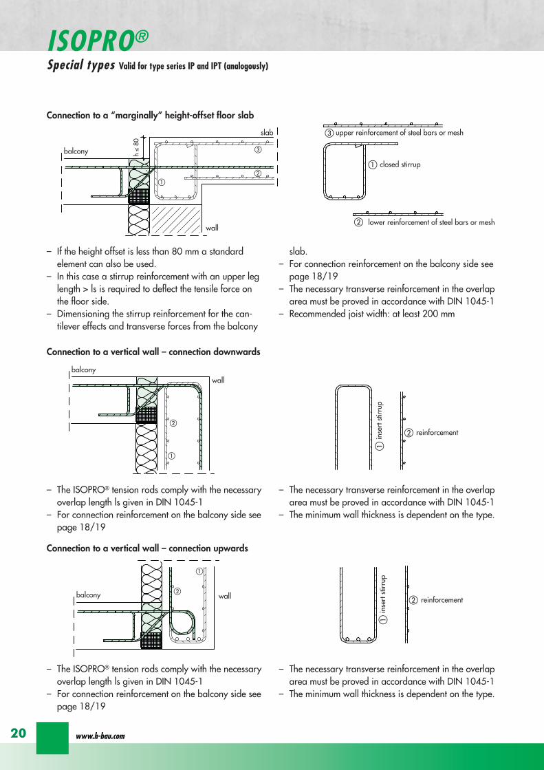
balcony
slab
wall
balcony
h lt
80
ab
c
a
b
c
aa
a
a
b
c
b
c
a
a
bb
a
c
c
ee
d
d
b
b
upper reinforcement of steel bars or mesh
lower reinforcement of steel bars or mesh
closed stirrup
inse
rt s
tirru
p
reinforcement
upper reinforcement of steel bars or mesh
lower reinforcement of steel bars or mesh
closed stirrup
upper reinforcement of steel bars or mesh
lower reinforcement of steel bars or mesh
clos
ed s
tirru
p
insert stirrup
parallel reinforcement
ain
sert
stir
rup
b
reinforcementb
wall
balcony wall
balcony
slab
balcony
slab
ndash If the height offset is less than 80 mm a standardelement can also be used
ndash In this case a stirrup reinforcement with an upper leglength gt ls is required to deflect the tensile force onthe floor side
ndash Dimensioning the stirrup reinforcement for the can-tilever effects and transverse forces from the balcony
slabndash For connection reinforcement on the balcony side see
page 1819ndash The necessary transverse reinforcement in the overlap
area must be proved in accordance with DIN 1045-1ndash Recommended joist width at least 200 mm
Connection to a ldquomarginallyrdquo height-offset floor slab
balcony
slab
wall
balcony
h lt
80
ab
c
a
b
c
a
a
a
a
b
c
b
c
a
a
bb
a
c
c
ee
d
d
b
b
upper reinforcement of steel bars or mesh
lower reinforcement of steel bars or mesh
closed stirrup
inse
rt s
tirru
p
reinforcement
upper reinforcement of steel bars or mesh
lower reinforcement of steel bars or mesh
closed stirrup
upper reinforcement of steel bars or mesh
lower reinforcement of steel bars or mesh
clos
ed s
tirru
p
insert stirrup
parallel reinforcement
ain
sert
stir
rup
b
reinforcementb
wall
balcony wall
balcony
slab
balcony
slab
ndash The ISOPROreg tension rods comply with the necessaryoverlap length ls given in DIN 1045-1
ndash For connection reinforcement on the balcony side seepage 1819
ndash The necessary transverse reinforcement in the overlaparea must be proved in accordance with DIN 1045-1
ndash The minimum wall thickness is dependent on the type
Connection to a vertical wall ndash connection downwards
balcony
slab
wall
balcony
h lt
80
ab
c
a
b
c
a
a
a
a
b
c
b
c
a
a
bb
a
c
c
ee
d
d
b
b
upper reinforcement of steel bars or mesh
lower reinforcement of steel bars or mesh
closed stirrup
inse
rt s
tirru
p
reinforcement
upper reinforcement of steel bars or mesh
lower reinforcement of steel bars or mesh
closed stirrup
upper reinforcement of steel bars or mesh
lower reinforcement of steel bars or mesh
clos
ed s
tirru
p
insert stirrup
parallel reinforcement
ain
sert
stir
rup
b
reinforcementb
wall
balcony wall
balcony
slab
balcony
slab
ndash The ISOPROreg tension rods comply with the necessaryoverlap length ls given in DIN 1045-1
ndash For connection reinforcement on the balcony side seepage 1819
ndash The necessary transverse reinforcement in the overlaparea must be proved in accordance with DIN 1045-1
ndash The minimum wall thickness is dependent on the type
Connection to a vertical wall ndash connection upwards
wwwh-baucom20
ISOPROreg
Special types Valid for type series IP and IPT (analogously)
balcony
slab
wall
balcony
h lt
80
ab
c
a
b
c
a
a
a
a
b
c
b
c
a
a
bb
a
c
c
ee
d
d
b
b
upper reinforcement of steel bars or mesh
lower reinforcement of steel bars or mesh
closed stirrup
inse
rt s
tirru
p
reinforcement
upper reinforcement of steel bars or mesh
lower reinforcement of steel bars or mesh
closed stirrup
upper reinforcement of steel bars or mesh
lower reinforcement of steel bars or mesh
clos
ed s
tirru
p
insert stirrup
parallel reinforcement
ain
sert
stir
rup
b
reinforcementb
wall
balcony wall
balcony
slab
balcony
slab
ndash dimensioning of the stirrup reinforcement for can-tilever effect and transverse force on the balcony slab
ndash the ISOPROreg tension rods comply with the DIN 1045-1 requirement for overlap length ls
ndash for on-site reinforcement see pages 1819
ndash the required transverse reinforcement in the overlapzone must be proven in compliance with DIN 1045-1
ndash recommended step-down width at least 220 mm
Connection to a floor slab with a step-up offset
balcony
slab
wall
balcony
h lt
80
ab
c
a
b
c
a
a
a
a
b
c
b
c
a
a
bb
a
c
c
ee
d
d
b
b
upper reinforcement of steel bars or mesh
lower reinforcement of steel bars or mesh
closed stirrup
inse
rt s
tirru
p
reinforcement
upper reinforcement of steel bars or mesh
lower reinforcement of steel bars or mesh
closed stirrup
upper reinforcement of steel bars or mesh
lower reinforcement of steel bars or mesh
clos
ed s
tirru
p
insert stirrup
parallel reinforcementa
inse
rt s
tirru
p
b
reinforcementb
wall
balcony wall
balcony
slab
balcony
slab
ndash dimensioning of the stirrup reinforcement for can-tilever effect and transverse force on the balcony slab
ndash the ISOPROreg tension rods comply with the DIN 1045-1 requirement for overlap length ls
ndash for on-site reinforcement see pages 1819
ndash the required transverse reinforcement in the overlapzone must be proven in compliance with DIN 1045-1
ndash constructive angle reinforcement pos 3ndash recommended step-down width at least 220 mm
Connection to a floor slab with step-down offset
ISOPROreg - Insulation at the highest level
for superior solutions
21
ISOPROreg
Special types Valid for type series IP and IPT (analogously)
After stripping freely-protruding concrete slabs experience a lowering of the slab edge This displacement is a com-bination of the deformation of the balcony insulation elements used and the bending of the slab itself These two de-formations are superimposed and compensated by raising the formworkThe calculations shown below give the required formwork height offset at the end of the cantilever which results fromthe ISOPROreg elements at 100 loading For the total height offset the slab deformation should be added in accor-dance with DIN 1045-1 The total height offset defined in the construction plans from the structural design engineershould take into account the planned direction of the drainage when rounding off the results
wwwh-baucom22
ISOPROreg
Deflection and height offset
Element height h [mm] IP 88IP 107IP 108
IP 127IP 128IP 129
IP 1210
IPT 1211IPT 1212IPT 1412
IPT 1414Concrete covering cv
30 35 40 45 50160 051 059 092 106
160 048 056 087 100160 170 045 053 082 094
160 170 043 050 077 089160 170 180 041 047 073 084
170 180 039 045 070 080170 180 190 037 043 067 079
180 190 035 041 064 073180 190 200 034 039 061 069
190 200 033 038 059 067190 200 210 031 036 056 064
200 210 030 035 054 062200 210 220 029 034 052 059
210 220 028 033 050 057210 220 230 027 031 049 055
220 230 026 030 047 053220 230 240 026 029 046 052
230 240 025 029 044 050230 240 250 024 028 043 049
240 250 023 027 042 047240 250 023 026 040 046
250 022 025 039 045250 021 025 038 043
Offset height of the balcony slab
ISOPROreg - Insulation at the highest level
for superior solutionsISOPROreg
Deflection and height offset
Example for defining the balcony slab height offset
mEd bending moment used to determine the height offset resulting from the ISOPROreg elementThe definitive load combination is decided by the structural engineer
mRd design moment of the ISOPROreg element taken from the dimensioning table on pages 16 and 17lk Cantilever length in [m]
ExampleCantilever length lk = 180 mSlab thickness h = 180 mmIntrinsic weight (slab and covering) g = 60 kNm2
Edge load (parapet) F = 15 kNmLive load p = 40 kNm2
Concrete covering cv = 30 mm
Design calculationsmEd= (g + p) x lk2 2 + F x lk = (60 middot 135 + 40 middot 15) middot 182 2 + 15 middot 18 middot 135 = 265 kNmmvEd = (g + p) x lk + F = (60 middot 135 + 40 middot 15) middot 18 + 15 middot 135 = 274 kNm
Selected ISOPROreg IP 127 cv 30 h = 180 mm mRd = 289 kNmm vRd = 415 kNm
Selected load combination for determination of the height offset resulting from the ISOPROreg element mEd= (g + p3) middot lk22 + F middot lk= (60 middot 135 + 403 middot 15) middot 182 2 + 15 middot 18 middot 135 =200 kNmm
uuml = 041 middot (265 289) middot 180 middot 10 = 67 mm
23
uuml [mm] = value from table middot (mEdmRd) middot lk [m] middot 10
wwwh-baucom24
The external concrete components must have expansion joints at right angles to the insulation layer in order to limitthe stress caused by changes in temperature The spacing of the joints e is given in the following table
balcony
ISOPRO ISOPRO
expansion joint
balcony
e 2
e 2
ISOPRO Type IPT Corner
expansion joint
seperation ofexpansion joints e
seperation ofexpansion joints e
expansion jointExpansion joint spacing for ISOPROreg Types IP und IPT
Rod diameter [mm] le 10 12 14 16 20
Joint spacing e [m] 130 113 101 92 80
balcony
ISOPRO ISOPRO
expansion joint
balcony
e 2
e 2
ISOPRO Type IPT Corner
expansion joint
seperation ofexpansion joints e
seperation ofexpansion joints e
expansion joint
expansion joint dowellingeg HED-S + plastic sleeves
ISOPROreg
Expansion joint spacing
For corner constructions the maximum rod leg length is e2
ISOPROreg - Insulation at the highest level
for superior solutions
25
a a
b
c
b
c
sup3100
In pre-cast units
Arrange the lower reinforcement layer including themesh support as per structural design Distance to in-sulation joint le 100 mm (applies to IP only)
Install lower section The last transverse rod in themesh must be placed as close as possible to the insula-tion observing the required concrete covering
For IP the transverse force rod can be under or on topof the mesh The mesh support should be lifted until itis underneath the tension reinforcement
Concrete the slab element
Locate and fix the associated upper section andwhere required intermediate section
Type IP is supplied with suspension reinforcement asstandard
On-site
Lay the necessary on-site reinforcement on the floorside
Lay the slab element on the pre-prepared timberbeams
Lay the necessary on-site reinforcement on the bal-cony side
Attach the associated upper section and where re-quired intermediate section Bind the tension strutto the on-site reinforcement
h = 210 to 250 mm
Important note fit additional insertion stirrups Oslash 620 or stirrup meshQ188A on the balcony side
In type IP pre-cast units In type IPT pre-cast units
a a
b
c
b
c
sup3100
Type IP on-site Type IPT on-site
Important noteThe type identification for lower and upper sections must match (see also colour identification) The direction of in-stallation (on the balcony side) is mandatory
ISOPROreg
Two-part elements
wwwh-baucom26
upper section
centre section
lower section
upper section
centre section
lower section
balcony balconyslab slab
Type IP Type IPT
Construction
All ISOPROreg elements of types IP and IPT can be supplied as two-part elements
General notes
ndash The permitted resultant stresses can be found in thetables on pages 16 and 17 of this technical information
ndash Intermediate sections can be supplied for height offsetcompensation in 20 and 40 mm thicknesses
ndash Type IP If the mesh supports are placed with a spacingof le 100 mm from the insulation joint no additionalsuspension reinforcement is required Instead asuspension reinforcement dimensioned for VRd shouldbe located along the insulation joints
ndash For information regarding the required formwork height off-set and the maximum spacing of expansion joints refer topages 22 23 and 24
ndash The adhesive labels (type designation) for the upper andlower sections must be identical Follow the instructions forthe balcony side and the floor side
The following elements also have an addi-tional colour coding
ISOPROreg Type Colour code
IP 107 greenIP 127 blueIP 128 yellowIP 1210 white
The continuity of the colour coding throughthe elements ensures correct matching everytime even for short sections
ISOPROreg
Two-part elements
ISOPROreg - Insulation at the highest level
for superior solutions
27
balcony sidebalcony side
section 1st position
section 2nd position
slab balcony
1st position
2nd
posi
tion
cv
cvslab balcony
slab balcony
section 1st position
section 2nd position
1st position
2nd
posi
tion
slab balcony
IPT 127 Corner 820mmIPT 1210 Corner 960mm
IPT 127 Corner 820mmIPT 1210 Corner 960mm
IPT
127
Cor
ner
820m
mIP
T 12
10
Cor
ner
960m
mIP
T 12
7 C
orne
r82
0mm
IPT
121
0 C
orne
r96
0mm
General notes
Area of application for type IPT-Corner from slab thickness h le 180 mmOn-site reinforcement using overlap joints in accordance with DIN 1045-12001-07 Section 126Please refer to the information regarding on-site reinforcement on page 29Special elements for h = 160 mm are possibleBecause of the compression level a minimum spacing of the floor-side filigree slabs from the insulation body of185 mm is required for the ISOPROreg IPT-Corner elements
Type Length of element [m] Tension rods Compression level Transverse force rods
IPT 107-Corner 050 + 050 5 Oslash 10 + 5 Oslash 10 2 x 4 compression block 2 Oslash 10 + 2 Oslash 10
IPT 127-Corner 062 + 062 6 Oslash 12 + 6 Oslash 12 12 Oslash 14 + 12 Oslash 14 3 Oslash 10 + 3 Oslash 10
IPT 1210-Corner 062 + 062 6 Oslash 14 + 6 Oslash 14 14 Oslash 14 + 14 Oslash 14 3 Oslash 12 + 3 Oslash 12
Configuration of the elements
IPT 107-Corner
ISOPROreg Type IPT EckConstruction and dimensions
wwwh-baucom28
Plate thickness [mm] referred to cv [mm] Dimensional values for acceptable load moments MRd [kNm]
30 35 IPT 107 Corner IPT 127 Corner IPT 1210 Corner- 180 169 277 320
180 - 178 292 337- 190 186 306 354
190 - 195 320 370- 200 203 335 387
200 - 212 349 404- 210 220 363 421
210 - 229 378 437- 220 237 392 454
220 - 246 406 471- 230 254 421 487
230 - 263 435 504- 240 271 449 521
240 - 280 463 537- 250 289 478 554
250 - 297 492 571Dimensional values for acceptable transverse forces VRd [kN]
h = 180 - 250 [mm] 483 724 1043
balcony sidebalcony side
section 1st position
section 2nd position
slab balcony
1st position
2nd
posi
tion
cv
cvslab balcony
slab balcony
section 1st position
section 2nd position
1st position
2nd
posi
tion
slab balcony
IPT 127 Corner 820mmIPT 1210 Corner 960mm
IPT 127 Corner 820mmIPT 1210 Corner 960mm
IPT
127
Cor
ner
820m
mIP
T 12
10
Cor
ner
960m
mIP
T 12
7 C
orne
r82
0mm
IPT
121
0 C
orne
r96
0mm
Dimensioning table for concrete gege C2025
IPT 127-CornerIPT 1210-Corner
ISOPROreg Type IPT CornerConstruction and dimensions
ISOPROreg - Insulation at the highest level
for superior solutions
29
1st position
2nd
posi
tion
balcony slab
a
da
b b
c c
dstarter bar 1st position supplementary reinforcement
supplementary reinforcement
supp
lem
enta
ry r
einf
orce
men
t
supp
lem
enta
ry r
einf
orce
men
t
starter bar 1st position
stra
ter
bar
2nd
posi
tion
star
ter
bar
2nd
posi
tion
Type IPT 107-Corner IPT 127-Corner IPT 1210-Corner
starter bar 1st position 5 Oslash 10 6 Oslash 12 6 Oslash 14
starter bar 2nd position 5 Oslash 10 6 Oslash 12 6 Oslash 14
Supplementaryreinforcement 5 Oslash 10 6 Oslash 12 6 Oslash 14
Supplementaryreinforcement 5 Oslash 10 6 Oslash 12 6 Oslash 14
extension of the tension reinforcement internally as well as externally length = 2 x balcony cantilever length
ISOPROreg Type IPT CornerOn-site reinforcement
wwwh-baucom30
ISOPROreg - Insulation at the highest level
for superior solutions
IPQ IPQIPH
IPH
IPH
IPH
IPQS IPQSIPH IPQQS IPQQSIPH
IPQ IPQ
IPQ
IPQQ IPQQ
IPQQ IPQQIP
QS
IPQ IPQ
IPQ
Z
IPQ
S tie rod inlower position
IPQQ IPQQ
IPQ
Z
IPQ
S tie rod inlower position
propped balcony
internal-corner balcony with props
ISOPROreg
Examples of transverse force elements
propped balcony
propped balcony with selective point connection
internal-corner balcony with props
inset balcony with tieback3-sided overlying loggia with tieback
propped balcony with selective point connection
31
wwwh-baucom32
1000
1000
balcony slab balcony slab
IPQ 86 495 mmIPQ 88 495 mmIPQ 106 615 mmIPQ 126 740 mm
IPQ 86 495 mmIPQ 88 495 mmIPQ 106 615 mmIPQ 126 740 mm80
370 80 150
Calculated values for acceptable transverse forces vRd [kNm]
Element height IPQ 64 IPQ 65 IPQ 66 IPQ 68 IPQ 610
160 - 250 mm 348 435 522 695 869
Type IPQ 64 IPQ 65 IPQ 66 IPQ 68 IPQ 610Length [mm] 1000 1000 1000 1000 1000
Transverse force rods 4 Oslash 6 5 Oslash 6 6 Oslash 6 8 Oslash 6 10 Oslash 6
Compression blocks 4 4 4 4 4needed As [cmsup2] 08 10 12 16 20
Dimensioning table - Type IPQ for concrete gege C2025
Configuration of the elements Type IPQ
section
Top view
ISOPROreg Type IPQConstruction and dimensions
IPQ 64 - 610
min Element hight depentend on rod diameter Oslash 10 h ge170 Oslash 12 h ge180 Oslash 14 h ge190
ISOPROreg - Insulation at the highest level
for superior solutions
33
balcony slab
upper reinforcement of steel bars or mesh
lower reinforcement of steel bars or mesh
transverse shear force reinforcement 2 Oslash 8
insert stirrup
ls ls
a
b
c
d
d
a
c
d
b
suspension reinforcemente
ed
secondary reinforcement 2 Oslash 8
concrete concrete
The on-site suspension reinforcement pos and should be calculated for VRd (cf type test No 0519) and loca-ted next to the transverse force rods A Oslash 8 mm steel distribution rod should be installed above and below The sus-pension reinforcement can be replaced by a mesh support (see type IP page 18)DIN 1045-1 Section 1033 applies to the proof of the transverse force capacity of the slabs without shear reinforce-ment For proof of the transverse force capacity of the slabs with shear reinforcement DIN 1045-1 Section 1034 ap-plies The maximum transmissible transverse force across the joints must be limited to 03 VRdmax zu begrenzen
ISOPROreg Type IPQOn-site reinforcement
Calculated values for acceptable transverse forces vRd [kNm]
Element height IPQ 86 IPQ 88 IPQ 106 IPQ 125 IPQ 126
160 - 250 mm 927 1236 1449 1739 2089
Type IPQ 86 IPQ 88 IPQ 106 IPQ 125 IPQ 126Length [mm] 1000 1000 1000 1000 1000
Transverse force rods 6 Oslash 8 8 Oslash 8 6 Oslash 10 5 Oslash 12 6 Oslash 12
Compression blocks 4 4 4 4 4needed As [cmsup2] 21 28 33 40 48
Configuration of the elements Type IPQ
min Element hight depentend on rod diameter Oslash 10 h ge170 Oslash 12 h ge180 Oslash 14 h ge190
wwwh-baucom34
ISOPROreg Type IPQS 2Construction and dimensions
balcony slab
balcony slab
Calculated values for acceptable transverse forces VRd [kN]
Element height IPQS 62 IPQS 82 IPQS 102 IPQS 122 IPQS 142
160 - 250 mm 174 309 483 695 947
Dimensioning table - Type IPQS2 for concrete gege C2025
Type IPQS 62 IPQS 82 IPQS 102 IPQS 122 IPQS 142
Element length [mm] 300 300 300 300 300
Transverse force rods 2 Oslash 6 2 Oslash 8 2 Oslash 10 2 Oslash 12 2 Oslash 14
Compression rods 2 Oslash 10 2 Oslash 10 3 Oslash 10 4 Oslash 12 4 Oslash 14needed As [cmsup2] 040 071 111 160 218
Configuration of the elements Type IPQS2
min Element height dependent on rod diameter Oslash 10 h ge170 Oslash 12 h ge180 Oslash 14 h ge190
IPQS 82 495mmIPQS102 615mmIPQS122 740mmIPQS 142 860mm
IPQS 62
IPQS 82 495mmIPQS102 615mmIPQS122 740mmIPQS 142 860mm
ISOPROreg - Insulation at the highest level
for superior solutions
35
Calculated values for acceptable transverse forces VRd [kN]
Element height IPQS 63 IPQS 83 IPQS 103 IPQS 123 IPQS 143
160 - 250 mm 261 464 724 1043 1420
Dimensioning table - Type IPQS3 for concrete gege C2025
Type IPQS 63 IPQS 83 IPQS 103 IPQS 123 IPQS 143
Element length [mm] 400 400 400 400 400
Transverse force rods 3 Oslash 6 3 Oslash 8 3 Oslash 10 3 Oslash 12 3 Oslash 14
Compression rods 2 Oslash 10 3 Oslash 10 4 Oslash 12 5 Oslash 12 6 Oslash 14needed As [cmsup2] 060 107 167 240 327
Configuration of the elements Type IPQS3
balcony slab
balcony slab
ISOPROreg Type IPQS 3Construction and dimensionsn
IPQS 83 495mmIPQS103 615mmIPQS123 740mmIPQS 143 860mm
IPQS 63
IPQS 83 495mmIPQS103 615mmIPQS123 740mmIPQS 143 860mm
min Element height dependent on rod diameter Oslash 10 h ge170 Oslash 12 h ge180 Oslash 14 h ge190
wwwh-baucom36
ISOPROreg Type IPQQConstruction and dimensions
1000
1000
balcony balconyslab slab
180 80 150 80165 165
370 80 80150
IPQQ 86 495 mmIPQQ 106 615 mmIPQQ 126 740 mm
IPQQ 86 495 mmIPQQ 106 615 mmIPQQ 126 740 mm
IPQQ 64 IPQQ 66IPQQ 68 IPQQ 610
Calculated values for acceptable transverse forces vRd [kNm]
Element height IPQQ 64 IPQQ 66 IPQQ 68 IPQQ 610 IPQQ 86 IPQQ 106 IPQQ 126
160 - 250 mm plusmn348 plusmn522 plusmn695 plusmn869 plusmn927 plusmn1449 plusmn2086
Type IPQQ 64 IPQQ 66 IPQQ 68 IPQQ 610 IPQQ 86 IPQQ 106 IPQQ 126Element length [mm] 500 + 500 500 + 500 500 + 500 500 + 500 500 + 500 500 + 500 500 + 500Transverse force rods 2x4 Oslash 6 2x6 Oslash 6 2x8 Oslash 6 2x10 Oslash 6 2x6 Oslash 8 2x6 Oslash 10 2x6 Oslash 12
Compression rods 4 Oslash 10 4 Oslash 10 6 Oslash 10 6 Oslash 10 6 Oslash 10 10 Oslash 10 10 Oslash 12needed As [cmsup2] 080 120 160 200 213 333 480
Dimensioning table - Type IPQQ for concrete gege C2025
Configuration of the elements Typ IPQQ
Top view
Section
min Element height dependent on rod diameter Oslash 10 h ge170 Oslash 12 h ge180 Oslash 14 h ge190
ISOPROreg - Insulation at the highest level
for superior solutions
37
ISOPROreg Type IPQQOn-site reinforcement
balcony slab
upper reinforcement of steel bars or mesh
lower reinforcement of steel bars or mesh
ls ls
b
c
a
c
d
b
insert stirrupa
d
dinsert stirrupa
ad
d
secondary reinforcement 2 Oslash 8
concrete concrete
secondary reinforcement 2 Oslash 8
The on-site suspension reinforcement pos should be calculated for VRd and located next to the transverse forcerods A Oslash 8 mm steel distribution rod should be installed above and below DIN 1045-1 Section 1033 applies to the proof of the transverse force capacity of the slabs without shear reinforce-ment For proof of the transverse force capacity of the slabs with shear reinforcement DIN 1045-1 Section 1034 ap-plies The maximum transmissible transverse force across the joints must be limited to 03 VRdmax
wwwh-baucom38
ISOPROreg Type IPQQS 2Construction and dimensions
balcony slab
balcony slab
Calculated values for acceptable transverse forces VRd [kN]
Element height IPQQS 62 IPQQS 82 IPQQS 102 IPQQS 122 IPQQS 142
160 - 250 mm plusmn174 plusmn309 plusmn483 plusmn695 plusmn947
Dimensioning table - Type IPQQS2 for concrete gege C2025
Type IPQQS 62 IPQQS 82 IPQQS 102 IPQQS 122 IPQQS 142
Element length [mm] 300 300 300 300 300
Transverse force rods 2x 2 Oslash 6 2x 2 Oslash 8 2x 2 Oslash 10 2x 2 Oslash 12 2x 2 Oslash 14
Compression rods 2 Oslash 10 2 Oslash 10 3 Oslash 10 4 Oslash 12 4 Oslash 14needed As [cmsup2] 040 071 111 160 218
Configuration of the elements Type IPQQS2
IPQQS 82 495mmIPQQS 102 615mmIPQQS 122 740mmIPQQS 142 860mm
IPQQS 62
IPQQS 82 495mmIPQQS 102 615mmIPQQS 122 740mmIPQQS 142 860mm
min Element height dependent on rod diameter Oslash 10 h ge170 Oslash 12 h ge180 Oslash 14 h ge190
ISOPROreg - Insulation at the highest level
for superior solutions
39
ISOPROreg Type IPQQS 3Construction and dimensions
balcony slab
balcony slab
Calculated values for acceptable transverse forces VRd [kN]
Element height IPQQS 63 IPQQS 83 IPQQS 103 IPQQS 123 IPQQS 143
160 - 250 mm plusmn261 plusmn464 plusmn724 plusmn1043 plusmn1420
Dimensioning table - Type IPQQS3 for concrete gege C2025
Type IPQQS 63 IPQQS 83 IPQQS 103 IPQQS 123 IPQQS 143
Element length [mm] 400 400 400 400 400
Transverse force rods 2x 3 Oslash 6 2x 3 Oslash 8 2x 3 Oslash 10 2x 3 Oslash 12 2x 3 Oslash 14
Compression rods 2 Oslash 10 3 Oslash 10 4 Oslash 12 5 Oslash 12 6 Oslash 14needed As [cmsup2] 060 107 167 240 327
Configuration of the elements Type IPQQS3
min Element height dependent on rod diameter Oslash 10 h ge170 Oslash 12 h ge180 Oslash 14 h ge190 alternatively in Element length 500 mm available
IPQQS 83 495mmIPQQS 103 615mmIPQQS 123 740mmIPQQS 143 860mm
IPQQS 63
IPQQS 83 495mmIPQQS 103 615mmIPQQS 123 740mmIPQQS 143 860mm
wwwh-baucom40
ISOPROreg Type IPTDConstruction and dimensions
IPTD IPTD
inset balcony
30
balcony slab
Top view
Section
Example
Table of Dimensions ndash Type IPTD [length in mm]
TypeTension rod Transverse force rod Compression rod Supplemental transverse force
ZL QL DL Q10L Q12LIPTD 126 820 497 820 617 742IPTD 127 820 497 820 617 742IPTD 1210 820 497 820 617 742IPTD 1212 820 497 820 617 742IPTD 1410 960 497 960 617 742
ISOPROreg - Insulation at the highest level
for superior solutions
41
ISOPROreg Type IPTDOn-site reinforcement
balcony slab
upper reinforcement of steelbars or mesh
lower reinforcement of steelbars or mesh
secondary reinforcement 2 Oslash 8
secondary reinforcement 2 Oslash 8
insert stirrup
ls ls
AA
a
b
c
d
d
a
c
d
b
lower reinforcement of steelbars or meshc
upper reinforcement of steelbars or meshb
d
insert stirrupee
b
c
a
a
Section A - A
ISOPRO transverse force rods ISOPRO compression rods
ISOPRO transverse force rods ISOPRO tension rods
d
concrete concrete
The on-site suspension reinforcement pos should be calculated for VRd and located next to the transverse forcerods A Oslash 8 mm steel distribution rod should be installed above and below DIN 1045-1 Section 1033 applies to the proof of the transverse force capacity of the slabs without shear reinforce-ment For proof of the transverse force capacity of the slabs with shear reinforcement DIN 1045-1 Section 1034 ap-plies The maximum transmissible transverse force across the joints must be limited to 03 VRdmax
wwwh-baucom42
ISOPROreg Type IPTDDimensioning table for concrete gege C2025
Plate thickness [mm] withreference to cv [mm] Rated values for moment loading mRd [kNmm]
30 35 IPTD 126IPTD 126
Q10IPTD 126
Q12IPTD 127
IPTD 127Q10
IPTD 127Q12
IPTD 1210
- 160 plusmn 145 - - plusmn 182 - - plusmn 253160 - plusmn 154 - - plusmn 193 - - plusmn 269- 170 plusmn 162 plusmn 146 - plusmn 204 plusmn 187 - plusmn 284
170 - plusmn 171 plusmn 154 - plusmn 214 plusmn 197 - plusmn 299- 180 plusmn 180 plusmn 162 plusmn 145 plusmn 225 plusmn 208 plusmn 190 plusmn 314
180 - plusmn 189 plusmn 170 plusmn 152 plusmn 236 plusmn 218 plusmn 199 plusmn 330- 190 plusmn 197 plusmn 178 plusmn 159 plusmn 247 plusmn 228 plusmn 209 plusmn 345
190 - plusmn 206 plusmn 186 plusmn 166 plusmn 258 plusmn 238 plusmn 218 plusmn 360- 200 plusmn 215 plusmn 194 plusmn 173 plusmn 269 plusmn 248 plusmn 227 plusmn 375
200 - plusmn 223 plusmn 202 plusmn 180 plusmn 280 plusmn 258 plusmn 236 plusmn 391- 210 plusmn 232 plusmn 209 plusmn 187 plusmn 291 plusmn 268 plusmn 246 plusmn 406
210 - plusmn 241 plusmn 217 plusmn 194 plusmn 302 plusmn 278 plusmn 255 plusmn 421- 220 plusmn 250 plusmn 225 plusmn 201 plusmn 313 plusmn 288 plusmn 264 plusmn 437
220 - plusmn 258 plusmn 233 plusmn 208 plusmn 324 plusmn 298 plusmn 273 plusmn 452- 230 plusmn 267 plusmn 241 plusmn 215 plusmn 335 plusmn 308 plusmn 283 plusmn 467
230 - plusmn 276 plusmn 249 plusmn 222 plusmn 346 plusmn 318 plusmn 292 plusmn 482- 240 plusmn 285 plusmn 257 plusmn 229 plusmn 357 plusmn 328 plusmn 301 plusmn 498
240 - plusmn 293 plusmn 265 plusmn 236 plusmn 368 plusmn 339 plusmn 310 plusmn 513- 250 plusmn 302 plusmn 272 plusmn 243 plusmn 379 plusmn 349 plusmn 320 plusmn 528
250 - plusmn 311 plusmn 280 plusmn 250 plusmn 390 plusmn 359 plusmn 329 plusmn 543
Rated values for transverse force loading vRd [kNm]
h = 160 - 250 [mm ] plusmn 415 plusmn 762 plusmn 1098 plusmn 415 plusmn 762 plusmn 1098 plusmn 415
Type IPTD 126 IPTD 126Q10
IPTD 126Q12
IPTD 127 IPTD 127Q10
IPTD 127Q12
IPTD 1210
Element lenght [mm] 500 + 500 500 + 500 500 + 500 500 + 500 500 + 500 500 + 500 500 + 500
Tension rods 6 Oslash 12 6 Oslash 12 6 Oslash 122 Oslash 10 + 6 Oslash 12
2 Oslash 10 + 6 Oslash 12
2 Oslash 10 +6 Oslash 12
10 Oslash 12
Transverse forcerods
2x4 Oslash 8 2x4 Oslash 10 2x4 Oslash 12 2x4 Oslash 8 2x4 Oslash 10 2x4 Oslash 12 2x4 Oslash 8
Compression rods 6 Oslash 12 6 Oslash 12 6 Oslash 122 Oslash 10 + 6 Oslash 12
2 Oslash 10 +6 Oslash 12
2 Oslash 10 +6 Oslash 12
10 Oslash 12
Configuration of the elements Type IPTD
ISOPROreg - Insulation at the highest level
for superior solutions
43
ISOPROreg Type IPTDDimensioning table for concrete gege C2025
Rated values for moment loading mRd [kNmm]
IPTD 1210Q10
IPTD 1210Q12
IPTD 1212IPTD 1212
Q10IPTD 1212
Q12IPTD 1410
IPTD 1410Q10
IPTD 1410Q12
- - plusmn 307 - - plusmn 349 - -- - plusmn 326 - - plusmn 371 - -
plusmn 268 - plusmn 345 plusmn 328 - plusmn 392 plusmn 377 -plusmn 282 - plusmn 363 plusmn 346 - plusmn 414 plusmn 397 -plusmn 297 plusmn 279 plusmn 382 plusmn 364 plusmn 346 plusmn 436 plusmn 418 plusmn 401plusmn 311 plusmn 293 plusmn 400 plusmn 381 plusmn 363 plusmn- 457 plusmn 439 plusmn 421plusmn 325 plusmn 306 plusmn 419 plusmn 399 plusmn 380 plusmn 479 plusmn 459 plusmn 441plusmn 340 plusmn 320 plusmn 437 plusmn 417 plusmn 397 plusmn 500 plusmn 480 plusmn 461plusmn 354 plusmn 333 plusmn 456 plusmn 434 plusmn 414 plusmn 522 plusmn 501 plusmn 480plusmn 369 plusmn 347 plusmn 474 plusmn 452 plusmn 430 plusmn 543 plusmn 522 plusmn 500plusmn 383 plusmn 361 plusmn 493 plusmn 470 plusmn 447 plusmn 565 plusmn 542 plusmn 520plusmn 397 plusmn 374 plusmn 511 plusmn 487 plusmn 464 plusmn 587 plusmn 563 plusmn 540plusmn 412 plusmn 388 plusmn 530 plusmn 505 plusmn 481 plusmn 608 plusmn 584 plusmn 560plusmn 426 plusmn 401 plusmn 548 plusmn 523 plusmn 498 plusmn 630 plusmn 604 plusmn 580plusmn 440 plusmn 415 plusmn 567 plusmn 540 plusmn 515 plusmn 351 plusmn 625 plusmn 600plusmn 455 plusmn 428 plusmn 585 plusmn 558 plusmn 531 plusmn 673 plusmn 646 plusmn 619plusmn 469 plusmn 442 plusmn 604 plusmn 576 plusmn 548 plusmn 694 plusmn 666 plusmn 639plusmn 484 plusmn 455 plusmn 622 plusmn 593 plusmn 565 plusmn 716 plusmn 687 plusmn 659plusmn 498 plusmn 469 plusmn 641 plusmn 611 plusmn 582 plusmn 737 plusmn 708 plusmn 679plusmn 512 plusmn 483 plusmn 659 plusmn 629 plusmn 599 plusmn 759 plusmn 728 plusmn 699
Rated values for transverse force loading vRd [kNm]
plusmn 762 plusmn 1098 plusmn 415 plusmn 762 plusmn 1098 plusmn 415 plusmn 762 plusmn 1098
IPTD 1210Q10
IPTD 1210Q12
IPTD 1212 IPTD 1212Q10
IPTD 1212Q12
IPTD 1410 IPTD 1410Q10
IPTD 1410Q12
500 + 500 500 + 500 500 + 500 500 + 500 500 + 500 500 + 500 500 + 500 500 + 500
10 Oslash 12 10 Oslash 12 12 Oslash 12 12 Oslash 12 12 Oslash 12 10 Oslash 14 10 Oslash 14 10 Oslash 14
2x4 Oslash 10 2x4 Oslash 12 2x4 Oslash 8 2x4 Oslash 10 2x4 Oslash 12 2x4 Oslash 8 2x4 Oslash 10 2x4 Oslash 12
10 Oslash 12 10 Oslash 12 12 Oslash 12 12 Oslash 12 12 Oslash 12 10 Oslash 14 10 Oslash 14 10 Oslash 14
wwwh-baucom44
ISOPROreg Type IPQZConstruction and dimensions
300
40
0
300
40
0
balcony slab
balcony slab
For restraint-free support with an IPQZ element it should be opposed by an IPQS element Both elements should bereinforced by a tieback which corresponds in diameter and rod count to the IPQS and IPQZAn on-site stirrup reinforcement is required to connect IPQS to the floor
Calculated values for acceptable transverse forces VRd [kN]
Element height IPQZ 62 IPQZ 82 IPQZ 102 IPQZ 122 IPQZ 142
160 - 250 mm 174 309 483 695 947
IPQZ 63 IPQZ 83 IPQZ 103 IPQZ 123 IPQZ 143
160 - 250 mm 261 464 724 1043 1420
Dimensioning table ndash Type IPQZ for concrete ge C2025
Type IPQZ 62 IPQZ 82 IPQZ 102 IPQZ 122 IPQZ 142Element lenght [mm] 300 300 300 300 300
Transverse force rods 2 Oslash 6 2 Oslash 8 2 Oslash 10 2 Oslash 12 2 Oslash 14
Configuration of the elements
Type IPQZ 63 IPQZ 83 IPQZ 103 IPQZ 123 IPQZ 143Element length [mm] 400 400 400 400 400
Transverse force rods 3 Oslash 6 3 Oslash 8 3 Oslash 10 3 Oslash 12 3 Oslash 14
min Element height dependent on rod diameter Oslash 10 h ge170 Oslash 12 h ge180 Oslash 14 h ge190
IPQZ 82 83 495mmIPQZ102 103 615mmIPQZ122 123 740mmIPQZ 142 143 860mm
IPQZ 82 83 495mmIPQZ102 103 615mmIPQZ122 123 740mmIPQZ 142 143 860mm
IPQZ 62 63
ISOPROreg - Insulation at the highest level
for superior solutions
45
ISOPROreg Type IPQZOn-site reinforcement
Type Tieback Insert stirrup for use with
IPQZ 62 2 Oslash 6 1 Oslash 6 IPQS 62
IPQZ 82 2 Oslash 8 1 Oslash 8 IPQS 82
IPQZ 102 2 Oslash 10 1 Oslash 10 IPQS 102
IPQZ 122 2 Oslash 12 2 Oslash 8 IPQS 122
IPQZ 142 2 Oslash 14 2 Oslash 10 IPQS 142
tie roda
b
stirrup for anchering tie rodb
a
slab slabbalcony
Typ IPQZ Typ IPQS
Type Tieback Insert stirrup for use with
IPQZ 63 3 Oslash 6 2 Oslash 6 IPQS 63
IPQZ 83 3 Oslash 8 2 Oslash 8 IPQS 83
IPQZ 103 3 Oslash 10 2 Oslash 10 IPQS 103
IPQZ 123 3 Oslash 12 3 Oslash 8 IPQS 123
IPQZ 143 3 Oslash 14 3 Oslash 10 IPQS 143
wwwh-baucom46
ISOPROreg Type IPHConstruction and dimensions
The ISOPROreg elements type IPH which absorb horizontal forces must only be used with ISOPROreg cantilever slabs ortransverse force connections
The number of IPH elements to be used is defined by the structural engineer whereby the expansion joint spacing mustbe maintained
When using ISOPROreg IPH elements the force absorption of the line connection must be reduced by the ratio of thelength of the IPH elements to the total connection length as a percentage
independent of cvReinforcement Length of
element
HRd
Transverse force Horizontal Transverse force Horizontal
IPH 1 2 x 1 Oslash 8 - 100 mm plusmn 74 kN -IPH 2 - 1 Oslash 10 100 mm - plusmn181 kNIPH 3 2 x 1 Oslash 8 1 Oslash 10 100 mm plusmn 74 kN plusmn 181 kN
Dimensioning table ndash Type IPH for concrete gege C2025
balcony slab
balcony slab
balcony slab
balcony slab
balcony slab
balcony slab
100
100
100
250 80 250
250 80 250
250 80 250IPH 1 for absorption of horizontal forces parallel to the insulation joint
IPH 2 for absorption of horizontal forces perpendicular to the insulation joint
IPH 3 for absorption of horizontal forces parallel and perpendicular to the insulation joint
ISOPROreg - Insulation at the highest level
for superior solutions
47
ISOPROreg Type IPHOn-site reinforcement
The installation of the ISOPROreg IPH elements is analogous to the installation of the ISOPROreg cantilever slabs or trans-verse force connectionsThe number and positions of the elements are defined in the structural detail The elements must be fixed in their posi-tions
plate slab balcony slab
ls ls
lower reinforcement of steel bars or mesh
d
lower reinforcement of steel bars or mesh
upper reinforcement of steel bars or mesh
a
aa
dc
d
insert stirrup
a
b
c
secondary reinforcement Oslash 8
b
c c
insert stirrup
wwwh-baucom48
ISOPROreg Type IPAConstruction and calculation values
29
0204
0608
1012
1416
1820
2422
2628
0204
0608
1012
1416
1820
2224
2628
0 +10 +20 +30 +40 +50-10-20-30-40-50
dimensioning axis
MEd
VEd
NEd
380
60
gt160
sup3 16
0
130
Section
Mathematical model ndash Static system Interaction diagram
NRd [kN]
M Rd[kNm]
DimensionsLength of element 350 mmFascia thickness 160 ndash 240 mmHeight of element from 160 mmThickness of insulation element 60 mm
ReinforcementTension rods 3 Oslash 8Compression rods 3 Oslash 8Transverse force rods 2 x 2 Oslash 6
Calculated values for NRd = 0MRd 29 kNmelementVRd plusmn 127 kNelement
ISOPROreg - Insulation at the highest level
for superior solutions
49
ISOPROreg Type IPAOn-site reinforcement and installation instructions
400
100
aa
bc
b c
dd
e
f
gh
h
e
g
h
f
inse
rt s
tirru
ps
conn
ectio
n re
info
rcem
ent
conn
ectio
n re
info
rcem
ent
steel bar Oslash 8
upper slab reinforcement
insert stirrups 3 Oslash 8 150 mmsupplied
insert stirrup as constructive edging
lower slab reinforcement
34
160
56 59 60 60 59 56
34
Section Plan
Installation instructions1 Lay lower reinforcement including edging
2 Install ISOPROreg elements type IPA Spacing in accordance with static requirements
3 Install positions and and tie together
4 Lay upper floor reinforcement and tie together with the ISOPROreg reinforcement element
5 Concrete the floor slab Ensure safe positioning
6 Attach the on-site insulation between the ISOPROreg elements
7 Lay the fascia reinforcement and including edging and tie together with the ISOPROreg elements
supplied insulation
Type IPAType IPA
350e = separation of elements
gt 80
gt 16
0
Spacing of the elements Spacing of expansion joints
Expansion joint spacing e le 78 mAbove corner e2 le 35 m
The parapet must be verified as being a continuous supporte = spacing of the elements in accordance with static requirements
wwwh-baucom50
+5 +15 +25 +35-5-15-25-35
05
10
15
0
MEd
NEdVEd
MRdVRd
dimensioning axis
ISOPROreg Type IPFConstruction and calculation values
42034
0
60
100
Section
Mathematical model ndash Static system Interaction diagram
DimensionsLength of element 350 mmHeight of element from 160 mmThickness of insulation element 60 mm
ReinforcementTension rods 3 Oslash 6Compression rods 3 Oslash 6Transverse force rods 2 Oslash 6
Calculated values for NRd = 0MRd plusmn 15 kNmelementVRd + 127 kNelement
NRd [kN]
M Rd[kN
m]
VRd = 127 kN
ISOPROreg - Insulation at the highest level
for superior solutions
51
ISOPROreg Type IPFOn-site reinforcement and installation instructions
b
a insert stirrup min Oslash 6 150 mm
upper slab reinforcement
ac
b
e
d
c lower slab reinforcement
est
eel b
ar Oslash
8
d2
inse
rt s
tirru
p m
in Oslash
6
150
mm
3333
56 59 60 60 59 56
160
350
Section
Plan
Installation instructions1 Lay lower reinforcement including edging
2 Install ISOPROreg elements type IPA Spacing in accordance with static requirements
3 Install positions and and tie together
4 Lay upper floor reinforcement and tie together with the ISOPROreg reinforcement element
5 Concrete the floor slab Ensure safe positioning
6 Attach the on-site insulation between the ISOPROreg elements
7 Lay the fascia reinforcement and including edging and tie together with the ISOPROreg elements
350
60
Type IPF Type IPF
e = separation of elements
supplied insulation
parapet
Spacing of the elements
Spacing of expansion joints
Expansion joint spacing e le 78 mAbove corner e2 le 35 m
The parapet must be verified as beinga continuous support e = spacing of the elements in accor-dance with static requirements
wwwh-baucom52
ISOPROreg Type IPOConstruction and calculation values
23 lK
+PRd
+HEd
lK
sliding film
reinforcedconcrete console
soft-fibre panel
sup3 18
0
sup3 150 60
725
130 60 535
350
sliding film
reinforcedconcrete console
soft-fibre panelsup3
180
sup3 150 60
725
130 60 535
350
Section
Plan Mathematical modelStatic system
DimensionsLength of element 350 mmHeight of element from 180 mmThickness of insulation element 60 mm
ReinforcementTension rods 3 Oslash 6Compression rods 3 Oslash 8Transverse force rods 2 Oslash 10
for Hed = 0 PRd plusmn 171 kNmelement max HRd + 184 kNelement
0 2 4 6 8 10 12 14 16 20 22 Horizontal force HEd [kN]
25
15
10
5
0
P Rd[kN] concrete gege C2530
concrete gege C2025
PRd = 23
PRd = 10
HEd
= 18
4
HEd
= 23
1
ISOPROreg - Insulation at the highest level
for superior solutions
53
ISOPROreg Type IPOOn-site reinforcement and installation instructions
slab
a
a
bde
b
c
c upper reinforcement of steel bars or mesh
lower reinforcement of steel bars or mesh
insert stirrupde
long
itudi
nal r
einf
orce
men
t
clos
ed s
tirru
p
concrete
concrete
Section Installation instructions
1 Lay lower reinforcement including edging
2 Install ISOPROreg elements type IPO Spacingin accordance with static requirements
3 Lay upper floor reinforcement and tie to-gether with the ISOPROreg reinforcement ele-ment
4 Attach the on-site insulation between the ISO-PROreg elements
5 Lay the console reinforcement and andtie together with the ISOPROreg elements Thefloor edge beam must be designed as a con-tinuous support
6 As far as practical the console and the floorshould be concreted simultaneously Ensuresecure positioning
reinforced concrete joist
ISOPRO Type IPO ISOPRO Type IPO
supplied insulation
e = separation of elements350
Spacing of the elements Spacing of expansion joints
Expansion joint spacing e le 78 mAbove corner e2 le 35 m
The parapet must be verified as being a continuous support e = spacing of the elements in accordance with static requirements
wwwh-baucom54
ISOPROreg Type IPSConstruction and calculation values
80
5050
80 ZL
balcony slab plate slab
wall
console
tension rod
transverse force bars
compression strut
ZL
QL
QL
DL
80
DL
100100
BSt 500 Nr Wst Nr 14571
BSt 500 Nr Wst Nr 14571
BSt 500 S
BSt 500 S
Section
80
5050
80 ZL
balcony slab plate slab
wall
console
tension rod
transverse force bars
compression strut
ZL
QL
QL
DL
80
DL
100100
BSt 500 Nr Wst Nr 14571
BSt 500 Nr Wst Nr 14571
BSt 500 S
BSt 500 S
Dimensions - Type IPS [length in mm]
Type Tension rod Transverse forcerod
Compressionrod
ZL QL DLIPS 1 690 500 430IPS 2 820 620 500IPS 3 960 745 570IPS 4 1550 865 600
Dimensioning table for concrete gege C2025Element hight 400 mm IPS 1 IPS 2 IPS 3 IPS 4
moment MRd [kNm] 221 294 375 624
transverse forces VRd [kN] 213 333 480 653
Type IPS 1 IPS 2 IPS 3 IPS 4
Element width [mm] 220 220 220 220
Tension rods 3 Oslash 10 3 Oslash 12 3 Oslash 14 4 Oslash 14
Transverse force rods 2 Oslash 8 2 Oslash 10 2 Oslash 12 2 Oslash 14
Compression rods 3 Oslash 12 3 Oslash 14 3 Oslash 16 3 Oslash 20
Other designs and dimensions are available on requestThe bonding area I underlies the determination of the anchoring lengths However if required the reinforcement rods can also be designed for bonding area II
Configuration of the elements
ISOPROreg - Insulation at the highest level
for superior solutions
55
ISOPROreg Type IPSOn-site reinforcement and installation instructions
wall plate reinforcement to structural calculations
tension rod
transverse force bars
compression strut
a
b
c
d
d
a
b
a closed stirrup
edging
c suspension reinforcementconcrete concrete
Installation instructions
1 Lay wall plate reinforcement to meet structural requirements2 Insert ISOPROreg element type IPS and tie together with the wall
reinforcement Transverse reinforcement in overlap zone in accordance with DIN 1045-1
3 Install and tie together beam reinforcement and according to structural calculations Pos edging in accordance withDIN 1045-1 Pos installed as a closed stirrup to avoid shearing
4 When concreting make sure that both sides are uniformly filled and compacted
5 Formwork offset for the beam in accordance with structural calculations
wall plate reinforcement to structural calculations
tension rod
transverse force bars
compression strut
a
b
c
d
d
a
b
a closed stirrup
edging
c suspension reinforcementconcrete concrete
80
b b
plate slab
Type IPS
wal
l pla
te
Type IPS wal
l pla
te
balcony slab
supplied insulation
Configuration of the elements Expansion joint spacing
TypeJoint spacing [m]
e
IPS 1 113
IPS 2 101
IPS 3 92
IPS 4 80
For corner constructions the maximumrod leg length is e2
wwwh-baucom56
ISOPROreg Type IPWConstruction and calculation values
ZL ZL80
420 420
QL QL
DL DL
290290
low
er s
ectio
n12
50ce
ntre
sec
tion
uppe
r se
ctio
n25
0
h =
150
- 3
50
m
80
balcony
balcony slab
slab
exte
rnal
wal
l
inte
rnal
wal
l
horizontal transverse force bars
horizontal transverse force bars
upper section bht in mm150-250 250 80
lower section bht in mm150-250 1250 80
Section
Table of Dimensions Type IPW [length in mm]
Type
Tension rod Transverseforce rod
Compressionrod
ZL QL DLIPW 1 600 423 270IPW 2 790 563 335IPW 3 980 653 410IPW 4 1170 783 470
Element width b = 150 ndash 250 mmElement height h = 150 ndash 350 mInsulation material thickness t = 80 mm
Dimensioning table for concrete gege C2025Calculated values for acceptable moments MRdy [kNm]
Element height [m] IPW 1 IPW 2 IPW 3 IPW 415 ndash 20 537 918 1169 154420 ndash 25 737 1267 1614 2132
gt 25 937 1616 2059 2720Calculated values for acceptable transverse forces [kN]
vRdz [kN] 412 622 1066 1535vRdy [kN] plusmn137 plusmn137 plusmn137 plusmn137
Type IPW 1 IPW 2 IPW 3 IPW 4Element height [m] ge150 ge150 ge150 ge150Tension rods 4 Oslash 6 4 Oslash 8 4 Oslash 10 4 Oslash 12Transverse force rods Qz 6 Oslash 6 6 Oslash 8 6 Oslash 10 6 Oslash 12Transverse force rods Qy 2 x 2 Oslash 6 2 x 2 Oslash 6 2 x 2 Oslash 6 2 x 2 Oslash 6Compression rods 6 Oslash 8 6 Oslash 10 6 Oslash 12 6 Oslash 14
Configuration of the elements
Moment effects from wind loading are absorbed bythe stiffening effect of the balcony slab
MRdz = 0
Bonding area II underlies the determination of theoverlap lengths On request the anchoring lengthscan also be dimensioned for bonding area I Designsand dimensions deviating from the standard ele-ments are available on request
ISOPROreg - Insulation at the highest level
for superior solutions
57
ISOPROreg Type IPWOn-site reinforcement and installation instructions
MRdz
VRdz VRdy
x
z
y
MRdy
Mathematical model ndash Static system
balcony slab
balcony slab
steel
mes
h re
info
rcem
ent
a
steel
mes
h re
info
rcem
ent
b
e connection reinforcementto structural calculations
f
insert stirrupas constructive edging c
c
d steel bar min 2 Oslash 8
concrete sup3 2025
exte
rnal
wal
l
inte
rnal
wal
l
insert stirrupas constructive edging
connection reinforcementto structural calculations
a bc c
d
d
steel bar min 2 Oslash 8
steel bar min 2 Oslash 8
insert stirrupinsert stirrupsteel mesh reinforcement steel mesh reinforcement
80
wall p
late
wall p
late
balcony slab
plate slab
Type IPWsupplied insulation
Type IPW
b b
e e e
Configuration of the elements
Installation instructions
1 Position internal wall reinforcement 2 Attach the constructive edging inter-
nally (insert stirrup)3 Starting at the bottom assemble the in-
dividual ISOPROreg elements type IPWand tie together with the wall reinforce-ment
4 Erect and internally and tie to-gether
5 Position the external wall reinforce-ments and in accordancewith structural design and tie to theISOPROreg elements
6 When concreting pay particular atten-tion to the positional security of the ele-ments It is recommended to fill andcompact both wall plates at the sametime
wwwh-baucom58
ISOPROreg
Approvals and Type testing
Approvals
ISOPRO Type IP Z-157-244ISOPRO Type IPT Z-157-243
Type testing
ISOPRO Type IP Test No 0517ISOPRO Type IPT Test No 0518ISOPRO Type IPQ Test No 0519
ISOPROreg - Insulation at the highest level
for superior solutions
59
ISOPROreg
Tender
___________________________________________________________________________
Scope Application area DIN 276013 Concrete and reinforced concrete Floor constructions
Structural installations__________________________________________________________________________________
ISOPROreg supporting and thermally insulating connection elements
01 supporting the balcony slab using ISOPROreg elements from H-BAU Technik GmbH02 required for installation03 m Type IP cv = mm h = mm04 m Type IPQ cv = mm h = mm05 part Type cv = mm h = mm
Special fabrication according to the following description
06 for thermal separation of the concrete07 for the storey floors pos 08 for the roofing pos 09 for 10 and11 for the balcony slap pos 12 for the loggia slab pos 13 for the cantilever slab pos 14 for the 15 in fire protection construction class F9016 the bonding is made in the reinforcement of pos and pos 17 deliver18 deliver install and bond with the connection reinforcement19 only install and bond with the connection reinforcement delivery provided20 the installation is made in accordance with instructions from
H-BAU Technik GmbHAm Guumlterbahnhof 2079771 Klettgau-ErzingenGermanyTel +49 (0) 77 42 92 15-20Fax +49 (0) 77 42 92 15-90
21 in accordance with the detail and reinforcement drawings no 22 material 23 wages 24 unit price
25 total price
wwwh-baucom60
NOTES
ISOPROreg - Insulation at the highest level
for superior solutions
61
NOTES
wwwh-baucom
Concreting with system
ISOPROreg
KESIIRAPIDOBATreg
JSDHEDFERBOXreg
BOXFERreg
GRIPRIPreg
PENTAFLEXreg
RIPINOXreg
WARMBORDreg
SCHALBORDreg
ZEMBORDreg
SCHALL-ISO ACCESSORIES
H-BAU Technik GmbHAm Guumlterbahnhof 20D-79771 Klettgau-ErzingenTel + 49 (0) 7742 92 15-20Fax + 49 (0) 7742 92 15-90infoklettgauh-baude
Produktion Nord-OstBrandenburger StraszligeD-14641 WachowTel + 49 (0) 3 3239 775-20Fax + 49 (0) 3 3239 775-90infoberlinh-baude
Balcony insulation elementsLifting anchorsShuttering tubesPush-in pegsReinforcement connectorsReinforcement connectorsMasonry connectorsSealing technologyRustproof stainless steelStop end panelsStop end panelsStop end panelsSound insulation elementsSpacers
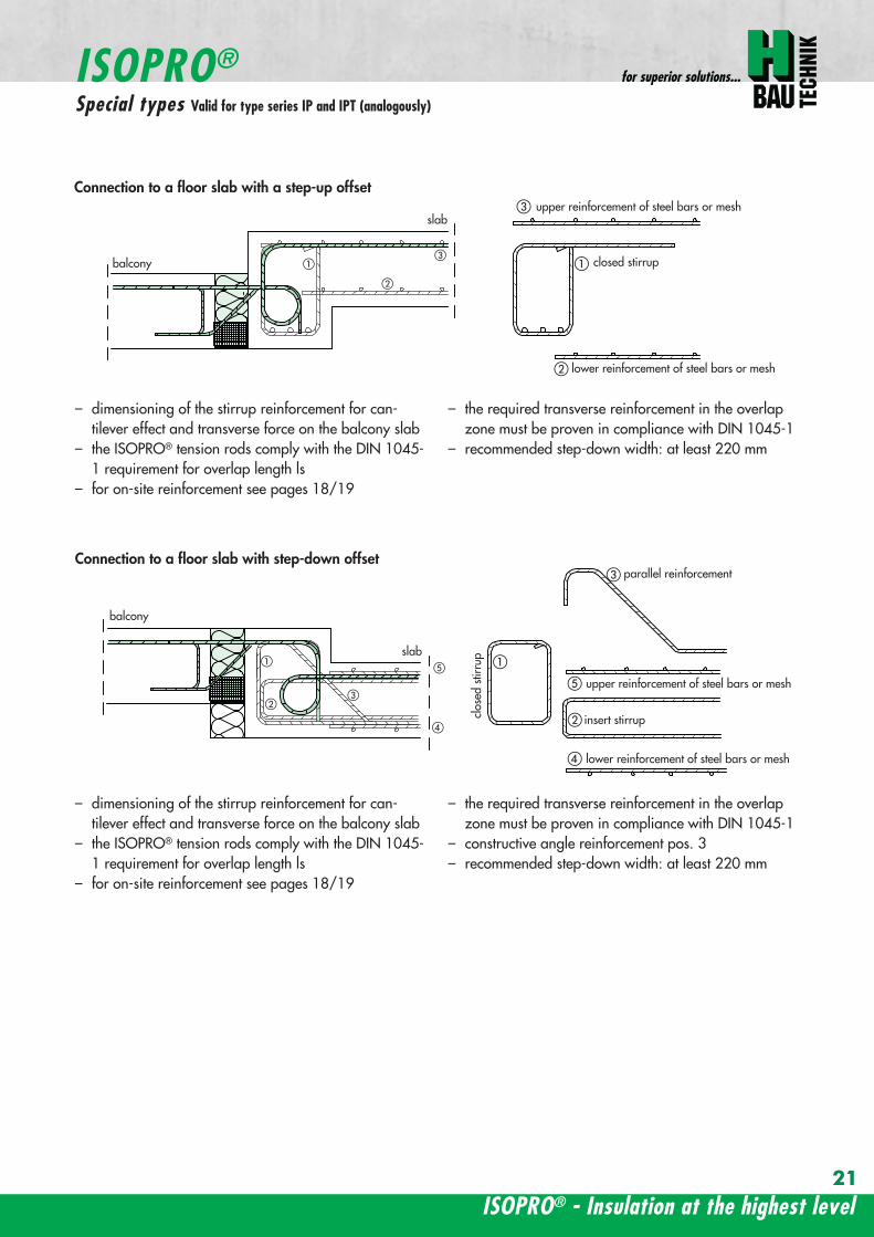
balcony
slab
wall
balcony
h lt
80
ab
c
a
b
c
a
a
a
a
b
c
b
c
a
a
bb
a
c
c
ee
d
d
b
b
upper reinforcement of steel bars or mesh
lower reinforcement of steel bars or mesh
closed stirrup
inse
rt s
tirru
p
reinforcement
upper reinforcement of steel bars or mesh
lower reinforcement of steel bars or mesh
closed stirrup
upper reinforcement of steel bars or mesh
lower reinforcement of steel bars or mesh
clos
ed s
tirru
p
insert stirrup
parallel reinforcement
ain
sert
stir
rup
b
reinforcementb
wall
balcony wall
balcony
slab
balcony
slab
ndash dimensioning of the stirrup reinforcement for can-tilever effect and transverse force on the balcony slab
ndash the ISOPROreg tension rods comply with the DIN 1045-1 requirement for overlap length ls
ndash for on-site reinforcement see pages 1819
ndash the required transverse reinforcement in the overlapzone must be proven in compliance with DIN 1045-1
ndash recommended step-down width at least 220 mm
Connection to a floor slab with a step-up offset
balcony
slab
wall
balcony
h lt
80
ab
c
a
b
c
a
a
a
a
b
c
b
c
a
a
bb
a
c
c
ee
d
d
b
b
upper reinforcement of steel bars or mesh
lower reinforcement of steel bars or mesh
closed stirrup
inse
rt s
tirru
p
reinforcement
upper reinforcement of steel bars or mesh
lower reinforcement of steel bars or mesh
closed stirrup
upper reinforcement of steel bars or mesh
lower reinforcement of steel bars or mesh
clos
ed s
tirru
p
insert stirrup
parallel reinforcementa
inse
rt s
tirru
p
b
reinforcementb
wall
balcony wall
balcony
slab
balcony
slab
ndash dimensioning of the stirrup reinforcement for can-tilever effect and transverse force on the balcony slab
ndash the ISOPROreg tension rods comply with the DIN 1045-1 requirement for overlap length ls
ndash for on-site reinforcement see pages 1819
ndash the required transverse reinforcement in the overlapzone must be proven in compliance with DIN 1045-1
ndash constructive angle reinforcement pos 3ndash recommended step-down width at least 220 mm
Connection to a floor slab with step-down offset
ISOPROreg - Insulation at the highest level
for superior solutions
21
ISOPROreg
Special types Valid for type series IP and IPT (analogously)
After stripping freely-protruding concrete slabs experience a lowering of the slab edge This displacement is a com-bination of the deformation of the balcony insulation elements used and the bending of the slab itself These two de-formations are superimposed and compensated by raising the formworkThe calculations shown below give the required formwork height offset at the end of the cantilever which results fromthe ISOPROreg elements at 100 loading For the total height offset the slab deformation should be added in accor-dance with DIN 1045-1 The total height offset defined in the construction plans from the structural design engineershould take into account the planned direction of the drainage when rounding off the results
wwwh-baucom22
ISOPROreg
Deflection and height offset
Element height h [mm] IP 88IP 107IP 108
IP 127IP 128IP 129
IP 1210
IPT 1211IPT 1212IPT 1412
IPT 1414Concrete covering cv
30 35 40 45 50160 051 059 092 106
160 048 056 087 100160 170 045 053 082 094
160 170 043 050 077 089160 170 180 041 047 073 084
170 180 039 045 070 080170 180 190 037 043 067 079
180 190 035 041 064 073180 190 200 034 039 061 069
190 200 033 038 059 067190 200 210 031 036 056 064
200 210 030 035 054 062200 210 220 029 034 052 059
210 220 028 033 050 057210 220 230 027 031 049 055
220 230 026 030 047 053220 230 240 026 029 046 052
230 240 025 029 044 050230 240 250 024 028 043 049
240 250 023 027 042 047240 250 023 026 040 046
250 022 025 039 045250 021 025 038 043
Offset height of the balcony slab
ISOPROreg - Insulation at the highest level
for superior solutionsISOPROreg
Deflection and height offset
Example for defining the balcony slab height offset
mEd bending moment used to determine the height offset resulting from the ISOPROreg elementThe definitive load combination is decided by the structural engineer
mRd design moment of the ISOPROreg element taken from the dimensioning table on pages 16 and 17lk Cantilever length in [m]
ExampleCantilever length lk = 180 mSlab thickness h = 180 mmIntrinsic weight (slab and covering) g = 60 kNm2
Edge load (parapet) F = 15 kNmLive load p = 40 kNm2
Concrete covering cv = 30 mm
Design calculationsmEd= (g + p) x lk2 2 + F x lk = (60 middot 135 + 40 middot 15) middot 182 2 + 15 middot 18 middot 135 = 265 kNmmvEd = (g + p) x lk + F = (60 middot 135 + 40 middot 15) middot 18 + 15 middot 135 = 274 kNm
Selected ISOPROreg IP 127 cv 30 h = 180 mm mRd = 289 kNmm vRd = 415 kNm
Selected load combination for determination of the height offset resulting from the ISOPROreg element mEd= (g + p3) middot lk22 + F middot lk= (60 middot 135 + 403 middot 15) middot 182 2 + 15 middot 18 middot 135 =200 kNmm
uuml = 041 middot (265 289) middot 180 middot 10 = 67 mm
23
uuml [mm] = value from table middot (mEdmRd) middot lk [m] middot 10
wwwh-baucom24
The external concrete components must have expansion joints at right angles to the insulation layer in order to limitthe stress caused by changes in temperature The spacing of the joints e is given in the following table
balcony
ISOPRO ISOPRO
expansion joint
balcony
e 2
e 2
ISOPRO Type IPT Corner
expansion joint
seperation ofexpansion joints e
seperation ofexpansion joints e
expansion jointExpansion joint spacing for ISOPROreg Types IP und IPT
Rod diameter [mm] le 10 12 14 16 20
Joint spacing e [m] 130 113 101 92 80
balcony
ISOPRO ISOPRO
expansion joint
balcony
e 2
e 2
ISOPRO Type IPT Corner
expansion joint
seperation ofexpansion joints e
seperation ofexpansion joints e
expansion joint
expansion joint dowellingeg HED-S + plastic sleeves
ISOPROreg
Expansion joint spacing
For corner constructions the maximum rod leg length is e2
ISOPROreg - Insulation at the highest level
for superior solutions
25
a a
b
c
b
c
sup3100
In pre-cast units
Arrange the lower reinforcement layer including themesh support as per structural design Distance to in-sulation joint le 100 mm (applies to IP only)
Install lower section The last transverse rod in themesh must be placed as close as possible to the insula-tion observing the required concrete covering
For IP the transverse force rod can be under or on topof the mesh The mesh support should be lifted until itis underneath the tension reinforcement
Concrete the slab element
Locate and fix the associated upper section andwhere required intermediate section
Type IP is supplied with suspension reinforcement asstandard
On-site
Lay the necessary on-site reinforcement on the floorside
Lay the slab element on the pre-prepared timberbeams
Lay the necessary on-site reinforcement on the bal-cony side
Attach the associated upper section and where re-quired intermediate section Bind the tension strutto the on-site reinforcement
h = 210 to 250 mm
Important note fit additional insertion stirrups Oslash 620 or stirrup meshQ188A on the balcony side
In type IP pre-cast units In type IPT pre-cast units
a a
b
c
b
c
sup3100
Type IP on-site Type IPT on-site
Important noteThe type identification for lower and upper sections must match (see also colour identification) The direction of in-stallation (on the balcony side) is mandatory
ISOPROreg
Two-part elements
wwwh-baucom26
upper section
centre section
lower section
upper section
centre section
lower section
balcony balconyslab slab
Type IP Type IPT
Construction
All ISOPROreg elements of types IP and IPT can be supplied as two-part elements
General notes
ndash The permitted resultant stresses can be found in thetables on pages 16 and 17 of this technical information
ndash Intermediate sections can be supplied for height offsetcompensation in 20 and 40 mm thicknesses
ndash Type IP If the mesh supports are placed with a spacingof le 100 mm from the insulation joint no additionalsuspension reinforcement is required Instead asuspension reinforcement dimensioned for VRd shouldbe located along the insulation joints
ndash For information regarding the required formwork height off-set and the maximum spacing of expansion joints refer topages 22 23 and 24
ndash The adhesive labels (type designation) for the upper andlower sections must be identical Follow the instructions forthe balcony side and the floor side
The following elements also have an addi-tional colour coding
ISOPROreg Type Colour code
IP 107 greenIP 127 blueIP 128 yellowIP 1210 white
The continuity of the colour coding throughthe elements ensures correct matching everytime even for short sections
ISOPROreg
Two-part elements
ISOPROreg - Insulation at the highest level
for superior solutions
27
balcony sidebalcony side
section 1st position
section 2nd position
slab balcony
1st position
2nd
posi
tion
cv
cvslab balcony
slab balcony
section 1st position
section 2nd position
1st position
2nd
posi
tion
slab balcony
IPT 127 Corner 820mmIPT 1210 Corner 960mm
IPT 127 Corner 820mmIPT 1210 Corner 960mm
IPT
127
Cor
ner
820m
mIP
T 12
10
Cor
ner
960m
mIP
T 12
7 C
orne
r82
0mm
IPT
121
0 C
orne
r96
0mm
General notes
Area of application for type IPT-Corner from slab thickness h le 180 mmOn-site reinforcement using overlap joints in accordance with DIN 1045-12001-07 Section 126Please refer to the information regarding on-site reinforcement on page 29Special elements for h = 160 mm are possibleBecause of the compression level a minimum spacing of the floor-side filigree slabs from the insulation body of185 mm is required for the ISOPROreg IPT-Corner elements
Type Length of element [m] Tension rods Compression level Transverse force rods
IPT 107-Corner 050 + 050 5 Oslash 10 + 5 Oslash 10 2 x 4 compression block 2 Oslash 10 + 2 Oslash 10
IPT 127-Corner 062 + 062 6 Oslash 12 + 6 Oslash 12 12 Oslash 14 + 12 Oslash 14 3 Oslash 10 + 3 Oslash 10
IPT 1210-Corner 062 + 062 6 Oslash 14 + 6 Oslash 14 14 Oslash 14 + 14 Oslash 14 3 Oslash 12 + 3 Oslash 12
Configuration of the elements
IPT 107-Corner
ISOPROreg Type IPT EckConstruction and dimensions
wwwh-baucom28
Plate thickness [mm] referred to cv [mm] Dimensional values for acceptable load moments MRd [kNm]
30 35 IPT 107 Corner IPT 127 Corner IPT 1210 Corner- 180 169 277 320
180 - 178 292 337- 190 186 306 354
190 - 195 320 370- 200 203 335 387
200 - 212 349 404- 210 220 363 421
210 - 229 378 437- 220 237 392 454
220 - 246 406 471- 230 254 421 487
230 - 263 435 504- 240 271 449 521
240 - 280 463 537- 250 289 478 554
250 - 297 492 571Dimensional values for acceptable transverse forces VRd [kN]
h = 180 - 250 [mm] 483 724 1043
balcony sidebalcony side
section 1st position
section 2nd position
slab balcony
1st position
2nd
posi
tion
cv
cvslab balcony
slab balcony
section 1st position
section 2nd position
1st position
2nd
posi
tion
slab balcony
IPT 127 Corner 820mmIPT 1210 Corner 960mm
IPT 127 Corner 820mmIPT 1210 Corner 960mm
IPT
127
Cor
ner
820m
mIP
T 12
10
Cor
ner
960m
mIP
T 12
7 C
orne
r82
0mm
IPT
121
0 C
orne
r96
0mm
Dimensioning table for concrete gege C2025
IPT 127-CornerIPT 1210-Corner
ISOPROreg Type IPT CornerConstruction and dimensions
ISOPROreg - Insulation at the highest level
for superior solutions
29
1st position
2nd
posi
tion
balcony slab
a
da
b b
c c
dstarter bar 1st position supplementary reinforcement
supplementary reinforcement
supp
lem
enta
ry r
einf
orce
men
t
supp
lem
enta
ry r
einf
orce
men
t
starter bar 1st position
stra
ter
bar
2nd
posi
tion
star
ter
bar
2nd
posi
tion
Type IPT 107-Corner IPT 127-Corner IPT 1210-Corner
starter bar 1st position 5 Oslash 10 6 Oslash 12 6 Oslash 14
starter bar 2nd position 5 Oslash 10 6 Oslash 12 6 Oslash 14
Supplementaryreinforcement 5 Oslash 10 6 Oslash 12 6 Oslash 14
Supplementaryreinforcement 5 Oslash 10 6 Oslash 12 6 Oslash 14
extension of the tension reinforcement internally as well as externally length = 2 x balcony cantilever length
ISOPROreg Type IPT CornerOn-site reinforcement
wwwh-baucom30
ISOPROreg - Insulation at the highest level
for superior solutions
IPQ IPQIPH
IPH
IPH
IPH
IPQS IPQSIPH IPQQS IPQQSIPH
IPQ IPQ
IPQ
IPQQ IPQQ
IPQQ IPQQIP
QS
IPQ IPQ
IPQ
Z
IPQ
S tie rod inlower position
IPQQ IPQQ
IPQ
Z
IPQ
S tie rod inlower position
propped balcony
internal-corner balcony with props
ISOPROreg
Examples of transverse force elements
propped balcony
propped balcony with selective point connection
internal-corner balcony with props
inset balcony with tieback3-sided overlying loggia with tieback
propped balcony with selective point connection
31
wwwh-baucom32
1000
1000
balcony slab balcony slab
IPQ 86 495 mmIPQ 88 495 mmIPQ 106 615 mmIPQ 126 740 mm
IPQ 86 495 mmIPQ 88 495 mmIPQ 106 615 mmIPQ 126 740 mm80
370 80 150
Calculated values for acceptable transverse forces vRd [kNm]
Element height IPQ 64 IPQ 65 IPQ 66 IPQ 68 IPQ 610
160 - 250 mm 348 435 522 695 869
Type IPQ 64 IPQ 65 IPQ 66 IPQ 68 IPQ 610Length [mm] 1000 1000 1000 1000 1000
Transverse force rods 4 Oslash 6 5 Oslash 6 6 Oslash 6 8 Oslash 6 10 Oslash 6
Compression blocks 4 4 4 4 4needed As [cmsup2] 08 10 12 16 20
Dimensioning table - Type IPQ for concrete gege C2025
Configuration of the elements Type IPQ
section
Top view
ISOPROreg Type IPQConstruction and dimensions
IPQ 64 - 610
min Element hight depentend on rod diameter Oslash 10 h ge170 Oslash 12 h ge180 Oslash 14 h ge190
ISOPROreg - Insulation at the highest level
for superior solutions
33
balcony slab
upper reinforcement of steel bars or mesh
lower reinforcement of steel bars or mesh
transverse shear force reinforcement 2 Oslash 8
insert stirrup
ls ls
a
b
c
d
d
a
c
d
b
suspension reinforcemente
ed
secondary reinforcement 2 Oslash 8
concrete concrete
The on-site suspension reinforcement pos and should be calculated for VRd (cf type test No 0519) and loca-ted next to the transverse force rods A Oslash 8 mm steel distribution rod should be installed above and below The sus-pension reinforcement can be replaced by a mesh support (see type IP page 18)DIN 1045-1 Section 1033 applies to the proof of the transverse force capacity of the slabs without shear reinforce-ment For proof of the transverse force capacity of the slabs with shear reinforcement DIN 1045-1 Section 1034 ap-plies The maximum transmissible transverse force across the joints must be limited to 03 VRdmax zu begrenzen
ISOPROreg Type IPQOn-site reinforcement
Calculated values for acceptable transverse forces vRd [kNm]
Element height IPQ 86 IPQ 88 IPQ 106 IPQ 125 IPQ 126
160 - 250 mm 927 1236 1449 1739 2089
Type IPQ 86 IPQ 88 IPQ 106 IPQ 125 IPQ 126Length [mm] 1000 1000 1000 1000 1000
Transverse force rods 6 Oslash 8 8 Oslash 8 6 Oslash 10 5 Oslash 12 6 Oslash 12
Compression blocks 4 4 4 4 4needed As [cmsup2] 21 28 33 40 48
Configuration of the elements Type IPQ
min Element hight depentend on rod diameter Oslash 10 h ge170 Oslash 12 h ge180 Oslash 14 h ge190
wwwh-baucom34
ISOPROreg Type IPQS 2Construction and dimensions
balcony slab
balcony slab
Calculated values for acceptable transverse forces VRd [kN]
Element height IPQS 62 IPQS 82 IPQS 102 IPQS 122 IPQS 142
160 - 250 mm 174 309 483 695 947
Dimensioning table - Type IPQS2 for concrete gege C2025
Type IPQS 62 IPQS 82 IPQS 102 IPQS 122 IPQS 142
Element length [mm] 300 300 300 300 300
Transverse force rods 2 Oslash 6 2 Oslash 8 2 Oslash 10 2 Oslash 12 2 Oslash 14
Compression rods 2 Oslash 10 2 Oslash 10 3 Oslash 10 4 Oslash 12 4 Oslash 14needed As [cmsup2] 040 071 111 160 218
Configuration of the elements Type IPQS2
min Element height dependent on rod diameter Oslash 10 h ge170 Oslash 12 h ge180 Oslash 14 h ge190
IPQS 82 495mmIPQS102 615mmIPQS122 740mmIPQS 142 860mm
IPQS 62
IPQS 82 495mmIPQS102 615mmIPQS122 740mmIPQS 142 860mm
ISOPROreg - Insulation at the highest level
for superior solutions
35
Calculated values for acceptable transverse forces VRd [kN]
Element height IPQS 63 IPQS 83 IPQS 103 IPQS 123 IPQS 143
160 - 250 mm 261 464 724 1043 1420
Dimensioning table - Type IPQS3 for concrete gege C2025
Type IPQS 63 IPQS 83 IPQS 103 IPQS 123 IPQS 143
Element length [mm] 400 400 400 400 400
Transverse force rods 3 Oslash 6 3 Oslash 8 3 Oslash 10 3 Oslash 12 3 Oslash 14
Compression rods 2 Oslash 10 3 Oslash 10 4 Oslash 12 5 Oslash 12 6 Oslash 14needed As [cmsup2] 060 107 167 240 327
Configuration of the elements Type IPQS3
balcony slab
balcony slab
ISOPROreg Type IPQS 3Construction and dimensionsn
IPQS 83 495mmIPQS103 615mmIPQS123 740mmIPQS 143 860mm
IPQS 63
IPQS 83 495mmIPQS103 615mmIPQS123 740mmIPQS 143 860mm
min Element height dependent on rod diameter Oslash 10 h ge170 Oslash 12 h ge180 Oslash 14 h ge190
wwwh-baucom36
ISOPROreg Type IPQQConstruction and dimensions
1000
1000
balcony balconyslab slab
180 80 150 80165 165
370 80 80150
IPQQ 86 495 mmIPQQ 106 615 mmIPQQ 126 740 mm
IPQQ 86 495 mmIPQQ 106 615 mmIPQQ 126 740 mm
IPQQ 64 IPQQ 66IPQQ 68 IPQQ 610
Calculated values for acceptable transverse forces vRd [kNm]
Element height IPQQ 64 IPQQ 66 IPQQ 68 IPQQ 610 IPQQ 86 IPQQ 106 IPQQ 126
160 - 250 mm plusmn348 plusmn522 plusmn695 plusmn869 plusmn927 plusmn1449 plusmn2086
Type IPQQ 64 IPQQ 66 IPQQ 68 IPQQ 610 IPQQ 86 IPQQ 106 IPQQ 126Element length [mm] 500 + 500 500 + 500 500 + 500 500 + 500 500 + 500 500 + 500 500 + 500Transverse force rods 2x4 Oslash 6 2x6 Oslash 6 2x8 Oslash 6 2x10 Oslash 6 2x6 Oslash 8 2x6 Oslash 10 2x6 Oslash 12
Compression rods 4 Oslash 10 4 Oslash 10 6 Oslash 10 6 Oslash 10 6 Oslash 10 10 Oslash 10 10 Oslash 12needed As [cmsup2] 080 120 160 200 213 333 480
Dimensioning table - Type IPQQ for concrete gege C2025
Configuration of the elements Typ IPQQ
Top view
Section
min Element height dependent on rod diameter Oslash 10 h ge170 Oslash 12 h ge180 Oslash 14 h ge190
ISOPROreg - Insulation at the highest level
for superior solutions
37
ISOPROreg Type IPQQOn-site reinforcement
balcony slab
upper reinforcement of steel bars or mesh
lower reinforcement of steel bars or mesh
ls ls
b
c
a
c
d
b
insert stirrupa
d
dinsert stirrupa
ad
d
secondary reinforcement 2 Oslash 8
concrete concrete
secondary reinforcement 2 Oslash 8
The on-site suspension reinforcement pos should be calculated for VRd and located next to the transverse forcerods A Oslash 8 mm steel distribution rod should be installed above and below DIN 1045-1 Section 1033 applies to the proof of the transverse force capacity of the slabs without shear reinforce-ment For proof of the transverse force capacity of the slabs with shear reinforcement DIN 1045-1 Section 1034 ap-plies The maximum transmissible transverse force across the joints must be limited to 03 VRdmax
wwwh-baucom38
ISOPROreg Type IPQQS 2Construction and dimensions
balcony slab
balcony slab
Calculated values for acceptable transverse forces VRd [kN]
Element height IPQQS 62 IPQQS 82 IPQQS 102 IPQQS 122 IPQQS 142
160 - 250 mm plusmn174 plusmn309 plusmn483 plusmn695 plusmn947
Dimensioning table - Type IPQQS2 for concrete gege C2025
Type IPQQS 62 IPQQS 82 IPQQS 102 IPQQS 122 IPQQS 142
Element length [mm] 300 300 300 300 300
Transverse force rods 2x 2 Oslash 6 2x 2 Oslash 8 2x 2 Oslash 10 2x 2 Oslash 12 2x 2 Oslash 14
Compression rods 2 Oslash 10 2 Oslash 10 3 Oslash 10 4 Oslash 12 4 Oslash 14needed As [cmsup2] 040 071 111 160 218
Configuration of the elements Type IPQQS2
IPQQS 82 495mmIPQQS 102 615mmIPQQS 122 740mmIPQQS 142 860mm
IPQQS 62
IPQQS 82 495mmIPQQS 102 615mmIPQQS 122 740mmIPQQS 142 860mm
min Element height dependent on rod diameter Oslash 10 h ge170 Oslash 12 h ge180 Oslash 14 h ge190
ISOPROreg - Insulation at the highest level
for superior solutions
39
ISOPROreg Type IPQQS 3Construction and dimensions
balcony slab
balcony slab
Calculated values for acceptable transverse forces VRd [kN]
Element height IPQQS 63 IPQQS 83 IPQQS 103 IPQQS 123 IPQQS 143
160 - 250 mm plusmn261 plusmn464 plusmn724 plusmn1043 plusmn1420
Dimensioning table - Type IPQQS3 for concrete gege C2025
Type IPQQS 63 IPQQS 83 IPQQS 103 IPQQS 123 IPQQS 143
Element length [mm] 400 400 400 400 400
Transverse force rods 2x 3 Oslash 6 2x 3 Oslash 8 2x 3 Oslash 10 2x 3 Oslash 12 2x 3 Oslash 14
Compression rods 2 Oslash 10 3 Oslash 10 4 Oslash 12 5 Oslash 12 6 Oslash 14needed As [cmsup2] 060 107 167 240 327
Configuration of the elements Type IPQQS3
min Element height dependent on rod diameter Oslash 10 h ge170 Oslash 12 h ge180 Oslash 14 h ge190 alternatively in Element length 500 mm available
IPQQS 83 495mmIPQQS 103 615mmIPQQS 123 740mmIPQQS 143 860mm
IPQQS 63
IPQQS 83 495mmIPQQS 103 615mmIPQQS 123 740mmIPQQS 143 860mm
wwwh-baucom40
ISOPROreg Type IPTDConstruction and dimensions
IPTD IPTD
inset balcony
30
balcony slab
Top view
Section
Example
Table of Dimensions ndash Type IPTD [length in mm]
TypeTension rod Transverse force rod Compression rod Supplemental transverse force
ZL QL DL Q10L Q12LIPTD 126 820 497 820 617 742IPTD 127 820 497 820 617 742IPTD 1210 820 497 820 617 742IPTD 1212 820 497 820 617 742IPTD 1410 960 497 960 617 742
ISOPROreg - Insulation at the highest level
for superior solutions
41
ISOPROreg Type IPTDOn-site reinforcement
balcony slab
upper reinforcement of steelbars or mesh
lower reinforcement of steelbars or mesh
secondary reinforcement 2 Oslash 8
secondary reinforcement 2 Oslash 8
insert stirrup
ls ls
AA
a
b
c
d
d
a
c
d
b
lower reinforcement of steelbars or meshc
upper reinforcement of steelbars or meshb
d
insert stirrupee
b
c
a
a
Section A - A
ISOPRO transverse force rods ISOPRO compression rods
ISOPRO transverse force rods ISOPRO tension rods
d
concrete concrete
The on-site suspension reinforcement pos should be calculated for VRd and located next to the transverse forcerods A Oslash 8 mm steel distribution rod should be installed above and below DIN 1045-1 Section 1033 applies to the proof of the transverse force capacity of the slabs without shear reinforce-ment For proof of the transverse force capacity of the slabs with shear reinforcement DIN 1045-1 Section 1034 ap-plies The maximum transmissible transverse force across the joints must be limited to 03 VRdmax
wwwh-baucom42
ISOPROreg Type IPTDDimensioning table for concrete gege C2025
Plate thickness [mm] withreference to cv [mm] Rated values for moment loading mRd [kNmm]
30 35 IPTD 126IPTD 126
Q10IPTD 126
Q12IPTD 127
IPTD 127Q10
IPTD 127Q12
IPTD 1210
- 160 plusmn 145 - - plusmn 182 - - plusmn 253160 - plusmn 154 - - plusmn 193 - - plusmn 269- 170 plusmn 162 plusmn 146 - plusmn 204 plusmn 187 - plusmn 284
170 - plusmn 171 plusmn 154 - plusmn 214 plusmn 197 - plusmn 299- 180 plusmn 180 plusmn 162 plusmn 145 plusmn 225 plusmn 208 plusmn 190 plusmn 314
180 - plusmn 189 plusmn 170 plusmn 152 plusmn 236 plusmn 218 plusmn 199 plusmn 330- 190 plusmn 197 plusmn 178 plusmn 159 plusmn 247 plusmn 228 plusmn 209 plusmn 345
190 - plusmn 206 plusmn 186 plusmn 166 plusmn 258 plusmn 238 plusmn 218 plusmn 360- 200 plusmn 215 plusmn 194 plusmn 173 plusmn 269 plusmn 248 plusmn 227 plusmn 375
200 - plusmn 223 plusmn 202 plusmn 180 plusmn 280 plusmn 258 plusmn 236 plusmn 391- 210 plusmn 232 plusmn 209 plusmn 187 plusmn 291 plusmn 268 plusmn 246 plusmn 406
210 - plusmn 241 plusmn 217 plusmn 194 plusmn 302 plusmn 278 plusmn 255 plusmn 421- 220 plusmn 250 plusmn 225 plusmn 201 plusmn 313 plusmn 288 plusmn 264 plusmn 437
220 - plusmn 258 plusmn 233 plusmn 208 plusmn 324 plusmn 298 plusmn 273 plusmn 452- 230 plusmn 267 plusmn 241 plusmn 215 plusmn 335 plusmn 308 plusmn 283 plusmn 467
230 - plusmn 276 plusmn 249 plusmn 222 plusmn 346 plusmn 318 plusmn 292 plusmn 482- 240 plusmn 285 plusmn 257 plusmn 229 plusmn 357 plusmn 328 plusmn 301 plusmn 498
240 - plusmn 293 plusmn 265 plusmn 236 plusmn 368 plusmn 339 plusmn 310 plusmn 513- 250 plusmn 302 plusmn 272 plusmn 243 plusmn 379 plusmn 349 plusmn 320 plusmn 528
250 - plusmn 311 plusmn 280 plusmn 250 plusmn 390 plusmn 359 plusmn 329 plusmn 543
Rated values for transverse force loading vRd [kNm]
h = 160 - 250 [mm ] plusmn 415 plusmn 762 plusmn 1098 plusmn 415 plusmn 762 plusmn 1098 plusmn 415
Type IPTD 126 IPTD 126Q10
IPTD 126Q12
IPTD 127 IPTD 127Q10
IPTD 127Q12
IPTD 1210
Element lenght [mm] 500 + 500 500 + 500 500 + 500 500 + 500 500 + 500 500 + 500 500 + 500
Tension rods 6 Oslash 12 6 Oslash 12 6 Oslash 122 Oslash 10 + 6 Oslash 12
2 Oslash 10 + 6 Oslash 12
2 Oslash 10 +6 Oslash 12
10 Oslash 12
Transverse forcerods
2x4 Oslash 8 2x4 Oslash 10 2x4 Oslash 12 2x4 Oslash 8 2x4 Oslash 10 2x4 Oslash 12 2x4 Oslash 8
Compression rods 6 Oslash 12 6 Oslash 12 6 Oslash 122 Oslash 10 + 6 Oslash 12
2 Oslash 10 +6 Oslash 12
2 Oslash 10 +6 Oslash 12
10 Oslash 12
Configuration of the elements Type IPTD
ISOPROreg - Insulation at the highest level
for superior solutions
43
ISOPROreg Type IPTDDimensioning table for concrete gege C2025
Rated values for moment loading mRd [kNmm]
IPTD 1210Q10
IPTD 1210Q12
IPTD 1212IPTD 1212
Q10IPTD 1212
Q12IPTD 1410
IPTD 1410Q10
IPTD 1410Q12
- - plusmn 307 - - plusmn 349 - -- - plusmn 326 - - plusmn 371 - -
plusmn 268 - plusmn 345 plusmn 328 - plusmn 392 plusmn 377 -plusmn 282 - plusmn 363 plusmn 346 - plusmn 414 plusmn 397 -plusmn 297 plusmn 279 plusmn 382 plusmn 364 plusmn 346 plusmn 436 plusmn 418 plusmn 401plusmn 311 plusmn 293 plusmn 400 plusmn 381 plusmn 363 plusmn- 457 plusmn 439 plusmn 421plusmn 325 plusmn 306 plusmn 419 plusmn 399 plusmn 380 plusmn 479 plusmn 459 plusmn 441plusmn 340 plusmn 320 plusmn 437 plusmn 417 plusmn 397 plusmn 500 plusmn 480 plusmn 461plusmn 354 plusmn 333 plusmn 456 plusmn 434 plusmn 414 plusmn 522 plusmn 501 plusmn 480plusmn 369 plusmn 347 plusmn 474 plusmn 452 plusmn 430 plusmn 543 plusmn 522 plusmn 500plusmn 383 plusmn 361 plusmn 493 plusmn 470 plusmn 447 plusmn 565 plusmn 542 plusmn 520plusmn 397 plusmn 374 plusmn 511 plusmn 487 plusmn 464 plusmn 587 plusmn 563 plusmn 540plusmn 412 plusmn 388 plusmn 530 plusmn 505 plusmn 481 plusmn 608 plusmn 584 plusmn 560plusmn 426 plusmn 401 plusmn 548 plusmn 523 plusmn 498 plusmn 630 plusmn 604 plusmn 580plusmn 440 plusmn 415 plusmn 567 plusmn 540 plusmn 515 plusmn 351 plusmn 625 plusmn 600plusmn 455 plusmn 428 plusmn 585 plusmn 558 plusmn 531 plusmn 673 plusmn 646 plusmn 619plusmn 469 plusmn 442 plusmn 604 plusmn 576 plusmn 548 plusmn 694 plusmn 666 plusmn 639plusmn 484 plusmn 455 plusmn 622 plusmn 593 plusmn 565 plusmn 716 plusmn 687 plusmn 659plusmn 498 plusmn 469 plusmn 641 plusmn 611 plusmn 582 plusmn 737 plusmn 708 plusmn 679plusmn 512 plusmn 483 plusmn 659 plusmn 629 plusmn 599 plusmn 759 plusmn 728 plusmn 699
Rated values for transverse force loading vRd [kNm]
plusmn 762 plusmn 1098 plusmn 415 plusmn 762 plusmn 1098 plusmn 415 plusmn 762 plusmn 1098
IPTD 1210Q10
IPTD 1210Q12
IPTD 1212 IPTD 1212Q10
IPTD 1212Q12
IPTD 1410 IPTD 1410Q10
IPTD 1410Q12
500 + 500 500 + 500 500 + 500 500 + 500 500 + 500 500 + 500 500 + 500 500 + 500
10 Oslash 12 10 Oslash 12 12 Oslash 12 12 Oslash 12 12 Oslash 12 10 Oslash 14 10 Oslash 14 10 Oslash 14
2x4 Oslash 10 2x4 Oslash 12 2x4 Oslash 8 2x4 Oslash 10 2x4 Oslash 12 2x4 Oslash 8 2x4 Oslash 10 2x4 Oslash 12
10 Oslash 12 10 Oslash 12 12 Oslash 12 12 Oslash 12 12 Oslash 12 10 Oslash 14 10 Oslash 14 10 Oslash 14
wwwh-baucom44
ISOPROreg Type IPQZConstruction and dimensions
300
40
0
300
40
0
balcony slab
balcony slab
For restraint-free support with an IPQZ element it should be opposed by an IPQS element Both elements should bereinforced by a tieback which corresponds in diameter and rod count to the IPQS and IPQZAn on-site stirrup reinforcement is required to connect IPQS to the floor
Calculated values for acceptable transverse forces VRd [kN]
Element height IPQZ 62 IPQZ 82 IPQZ 102 IPQZ 122 IPQZ 142
160 - 250 mm 174 309 483 695 947
IPQZ 63 IPQZ 83 IPQZ 103 IPQZ 123 IPQZ 143
160 - 250 mm 261 464 724 1043 1420
Dimensioning table ndash Type IPQZ for concrete ge C2025
Type IPQZ 62 IPQZ 82 IPQZ 102 IPQZ 122 IPQZ 142Element lenght [mm] 300 300 300 300 300
Transverse force rods 2 Oslash 6 2 Oslash 8 2 Oslash 10 2 Oslash 12 2 Oslash 14
Configuration of the elements
Type IPQZ 63 IPQZ 83 IPQZ 103 IPQZ 123 IPQZ 143Element length [mm] 400 400 400 400 400
Transverse force rods 3 Oslash 6 3 Oslash 8 3 Oslash 10 3 Oslash 12 3 Oslash 14
min Element height dependent on rod diameter Oslash 10 h ge170 Oslash 12 h ge180 Oslash 14 h ge190
IPQZ 82 83 495mmIPQZ102 103 615mmIPQZ122 123 740mmIPQZ 142 143 860mm
IPQZ 82 83 495mmIPQZ102 103 615mmIPQZ122 123 740mmIPQZ 142 143 860mm
IPQZ 62 63
ISOPROreg - Insulation at the highest level
for superior solutions
45
ISOPROreg Type IPQZOn-site reinforcement
Type Tieback Insert stirrup for use with
IPQZ 62 2 Oslash 6 1 Oslash 6 IPQS 62
IPQZ 82 2 Oslash 8 1 Oslash 8 IPQS 82
IPQZ 102 2 Oslash 10 1 Oslash 10 IPQS 102
IPQZ 122 2 Oslash 12 2 Oslash 8 IPQS 122
IPQZ 142 2 Oslash 14 2 Oslash 10 IPQS 142
tie roda
b
stirrup for anchering tie rodb
a
slab slabbalcony
Typ IPQZ Typ IPQS
Type Tieback Insert stirrup for use with
IPQZ 63 3 Oslash 6 2 Oslash 6 IPQS 63
IPQZ 83 3 Oslash 8 2 Oslash 8 IPQS 83
IPQZ 103 3 Oslash 10 2 Oslash 10 IPQS 103
IPQZ 123 3 Oslash 12 3 Oslash 8 IPQS 123
IPQZ 143 3 Oslash 14 3 Oslash 10 IPQS 143
wwwh-baucom46
ISOPROreg Type IPHConstruction and dimensions
The ISOPROreg elements type IPH which absorb horizontal forces must only be used with ISOPROreg cantilever slabs ortransverse force connections
The number of IPH elements to be used is defined by the structural engineer whereby the expansion joint spacing mustbe maintained
When using ISOPROreg IPH elements the force absorption of the line connection must be reduced by the ratio of thelength of the IPH elements to the total connection length as a percentage
independent of cvReinforcement Length of
element
HRd
Transverse force Horizontal Transverse force Horizontal
IPH 1 2 x 1 Oslash 8 - 100 mm plusmn 74 kN -IPH 2 - 1 Oslash 10 100 mm - plusmn181 kNIPH 3 2 x 1 Oslash 8 1 Oslash 10 100 mm plusmn 74 kN plusmn 181 kN
Dimensioning table ndash Type IPH for concrete gege C2025
balcony slab
balcony slab
balcony slab
balcony slab
balcony slab
balcony slab
100
100
100
250 80 250
250 80 250
250 80 250IPH 1 for absorption of horizontal forces parallel to the insulation joint
IPH 2 for absorption of horizontal forces perpendicular to the insulation joint
IPH 3 for absorption of horizontal forces parallel and perpendicular to the insulation joint
ISOPROreg - Insulation at the highest level
for superior solutions
47
ISOPROreg Type IPHOn-site reinforcement
The installation of the ISOPROreg IPH elements is analogous to the installation of the ISOPROreg cantilever slabs or trans-verse force connectionsThe number and positions of the elements are defined in the structural detail The elements must be fixed in their posi-tions
plate slab balcony slab
ls ls
lower reinforcement of steel bars or mesh
d
lower reinforcement of steel bars or mesh
upper reinforcement of steel bars or mesh
a
aa
dc
d
insert stirrup
a
b
c
secondary reinforcement Oslash 8
b
c c
insert stirrup
wwwh-baucom48
ISOPROreg Type IPAConstruction and calculation values
29
0204
0608
1012
1416
1820
2422
2628
0204
0608
1012
1416
1820
2224
2628
0 +10 +20 +30 +40 +50-10-20-30-40-50
dimensioning axis
MEd
VEd
NEd
380
60
gt160
sup3 16
0
130
Section
Mathematical model ndash Static system Interaction diagram
NRd [kN]
M Rd[kNm]
DimensionsLength of element 350 mmFascia thickness 160 ndash 240 mmHeight of element from 160 mmThickness of insulation element 60 mm
ReinforcementTension rods 3 Oslash 8Compression rods 3 Oslash 8Transverse force rods 2 x 2 Oslash 6
Calculated values for NRd = 0MRd 29 kNmelementVRd plusmn 127 kNelement
ISOPROreg - Insulation at the highest level
for superior solutions
49
ISOPROreg Type IPAOn-site reinforcement and installation instructions
400
100
aa
bc
b c
dd
e
f
gh
h
e
g
h
f
inse
rt s
tirru
ps
conn
ectio
n re
info
rcem
ent
conn
ectio
n re
info
rcem
ent
steel bar Oslash 8
upper slab reinforcement
insert stirrups 3 Oslash 8 150 mmsupplied
insert stirrup as constructive edging
lower slab reinforcement
34
160
56 59 60 60 59 56
34
Section Plan
Installation instructions1 Lay lower reinforcement including edging
2 Install ISOPROreg elements type IPA Spacing in accordance with static requirements
3 Install positions and and tie together
4 Lay upper floor reinforcement and tie together with the ISOPROreg reinforcement element
5 Concrete the floor slab Ensure safe positioning
6 Attach the on-site insulation between the ISOPROreg elements
7 Lay the fascia reinforcement and including edging and tie together with the ISOPROreg elements
supplied insulation
Type IPAType IPA
350e = separation of elements
gt 80
gt 16
0
Spacing of the elements Spacing of expansion joints
Expansion joint spacing e le 78 mAbove corner e2 le 35 m
The parapet must be verified as being a continuous supporte = spacing of the elements in accordance with static requirements
wwwh-baucom50
+5 +15 +25 +35-5-15-25-35
05
10
15
0
MEd
NEdVEd
MRdVRd
dimensioning axis
ISOPROreg Type IPFConstruction and calculation values
42034
0
60
100
Section
Mathematical model ndash Static system Interaction diagram
DimensionsLength of element 350 mmHeight of element from 160 mmThickness of insulation element 60 mm
ReinforcementTension rods 3 Oslash 6Compression rods 3 Oslash 6Transverse force rods 2 Oslash 6
Calculated values for NRd = 0MRd plusmn 15 kNmelementVRd + 127 kNelement
NRd [kN]
M Rd[kN
m]
VRd = 127 kN
ISOPROreg - Insulation at the highest level
for superior solutions
51
ISOPROreg Type IPFOn-site reinforcement and installation instructions
b
a insert stirrup min Oslash 6 150 mm
upper slab reinforcement
ac
b
e
d
c lower slab reinforcement
est
eel b
ar Oslash
8
d2
inse
rt s
tirru
p m
in Oslash
6
150
mm
3333
56 59 60 60 59 56
160
350
Section
Plan
Installation instructions1 Lay lower reinforcement including edging
2 Install ISOPROreg elements type IPA Spacing in accordance with static requirements
3 Install positions and and tie together
4 Lay upper floor reinforcement and tie together with the ISOPROreg reinforcement element
5 Concrete the floor slab Ensure safe positioning
6 Attach the on-site insulation between the ISOPROreg elements
7 Lay the fascia reinforcement and including edging and tie together with the ISOPROreg elements
350
60
Type IPF Type IPF
e = separation of elements
supplied insulation
parapet
Spacing of the elements
Spacing of expansion joints
Expansion joint spacing e le 78 mAbove corner e2 le 35 m
The parapet must be verified as beinga continuous support e = spacing of the elements in accor-dance with static requirements
wwwh-baucom52
ISOPROreg Type IPOConstruction and calculation values
23 lK
+PRd
+HEd
lK
sliding film
reinforcedconcrete console
soft-fibre panel
sup3 18
0
sup3 150 60
725
130 60 535
350
sliding film
reinforcedconcrete console
soft-fibre panelsup3
180
sup3 150 60
725
130 60 535
350
Section
Plan Mathematical modelStatic system
DimensionsLength of element 350 mmHeight of element from 180 mmThickness of insulation element 60 mm
ReinforcementTension rods 3 Oslash 6Compression rods 3 Oslash 8Transverse force rods 2 Oslash 10
for Hed = 0 PRd plusmn 171 kNmelement max HRd + 184 kNelement
0 2 4 6 8 10 12 14 16 20 22 Horizontal force HEd [kN]
25
15
10
5
0
P Rd[kN] concrete gege C2530
concrete gege C2025
PRd = 23
PRd = 10
HEd
= 18
4
HEd
= 23
1
ISOPROreg - Insulation at the highest level
for superior solutions
53
ISOPROreg Type IPOOn-site reinforcement and installation instructions
slab
a
a
bde
b
c
c upper reinforcement of steel bars or mesh
lower reinforcement of steel bars or mesh
insert stirrupde
long
itudi
nal r
einf
orce
men
t
clos
ed s
tirru
p
concrete
concrete
Section Installation instructions
1 Lay lower reinforcement including edging
2 Install ISOPROreg elements type IPO Spacingin accordance with static requirements
3 Lay upper floor reinforcement and tie to-gether with the ISOPROreg reinforcement ele-ment
4 Attach the on-site insulation between the ISO-PROreg elements
5 Lay the console reinforcement and andtie together with the ISOPROreg elements Thefloor edge beam must be designed as a con-tinuous support
6 As far as practical the console and the floorshould be concreted simultaneously Ensuresecure positioning
reinforced concrete joist
ISOPRO Type IPO ISOPRO Type IPO
supplied insulation
e = separation of elements350
Spacing of the elements Spacing of expansion joints
Expansion joint spacing e le 78 mAbove corner e2 le 35 m
The parapet must be verified as being a continuous support e = spacing of the elements in accordance with static requirements
wwwh-baucom54
ISOPROreg Type IPSConstruction and calculation values
80
5050
80 ZL
balcony slab plate slab
wall
console
tension rod
transverse force bars
compression strut
ZL
QL
QL
DL
80
DL
100100
BSt 500 Nr Wst Nr 14571
BSt 500 Nr Wst Nr 14571
BSt 500 S
BSt 500 S
Section
80
5050
80 ZL
balcony slab plate slab
wall
console
tension rod
transverse force bars
compression strut
ZL
QL
QL
DL
80
DL
100100
BSt 500 Nr Wst Nr 14571
BSt 500 Nr Wst Nr 14571
BSt 500 S
BSt 500 S
Dimensions - Type IPS [length in mm]
Type Tension rod Transverse forcerod
Compressionrod
ZL QL DLIPS 1 690 500 430IPS 2 820 620 500IPS 3 960 745 570IPS 4 1550 865 600
Dimensioning table for concrete gege C2025Element hight 400 mm IPS 1 IPS 2 IPS 3 IPS 4
moment MRd [kNm] 221 294 375 624
transverse forces VRd [kN] 213 333 480 653
Type IPS 1 IPS 2 IPS 3 IPS 4
Element width [mm] 220 220 220 220
Tension rods 3 Oslash 10 3 Oslash 12 3 Oslash 14 4 Oslash 14
Transverse force rods 2 Oslash 8 2 Oslash 10 2 Oslash 12 2 Oslash 14
Compression rods 3 Oslash 12 3 Oslash 14 3 Oslash 16 3 Oslash 20
Other designs and dimensions are available on requestThe bonding area I underlies the determination of the anchoring lengths However if required the reinforcement rods can also be designed for bonding area II
Configuration of the elements
ISOPROreg - Insulation at the highest level
for superior solutions
55
ISOPROreg Type IPSOn-site reinforcement and installation instructions
wall plate reinforcement to structural calculations
tension rod
transverse force bars
compression strut
a
b
c
d
d
a
b
a closed stirrup
edging
c suspension reinforcementconcrete concrete
Installation instructions
1 Lay wall plate reinforcement to meet structural requirements2 Insert ISOPROreg element type IPS and tie together with the wall
reinforcement Transverse reinforcement in overlap zone in accordance with DIN 1045-1
3 Install and tie together beam reinforcement and according to structural calculations Pos edging in accordance withDIN 1045-1 Pos installed as a closed stirrup to avoid shearing
4 When concreting make sure that both sides are uniformly filled and compacted
5 Formwork offset for the beam in accordance with structural calculations
wall plate reinforcement to structural calculations
tension rod
transverse force bars
compression strut
a
b
c
d
d
a
b
a closed stirrup
edging
c suspension reinforcementconcrete concrete
80
b b
plate slab
Type IPS
wal
l pla
te
Type IPS wal
l pla
te
balcony slab
supplied insulation
Configuration of the elements Expansion joint spacing
TypeJoint spacing [m]
e
IPS 1 113
IPS 2 101
IPS 3 92
IPS 4 80
For corner constructions the maximumrod leg length is e2
wwwh-baucom56
ISOPROreg Type IPWConstruction and calculation values
ZL ZL80
420 420
QL QL
DL DL
290290
low
er s
ectio
n12
50ce
ntre
sec
tion
uppe
r se
ctio
n25
0
h =
150
- 3
50
m
80
balcony
balcony slab
slab
exte
rnal
wal
l
inte
rnal
wal
l
horizontal transverse force bars
horizontal transverse force bars
upper section bht in mm150-250 250 80
lower section bht in mm150-250 1250 80
Section
Table of Dimensions Type IPW [length in mm]
Type
Tension rod Transverseforce rod
Compressionrod
ZL QL DLIPW 1 600 423 270IPW 2 790 563 335IPW 3 980 653 410IPW 4 1170 783 470
Element width b = 150 ndash 250 mmElement height h = 150 ndash 350 mInsulation material thickness t = 80 mm
Dimensioning table for concrete gege C2025Calculated values for acceptable moments MRdy [kNm]
Element height [m] IPW 1 IPW 2 IPW 3 IPW 415 ndash 20 537 918 1169 154420 ndash 25 737 1267 1614 2132
gt 25 937 1616 2059 2720Calculated values for acceptable transverse forces [kN]
vRdz [kN] 412 622 1066 1535vRdy [kN] plusmn137 plusmn137 plusmn137 plusmn137
Type IPW 1 IPW 2 IPW 3 IPW 4Element height [m] ge150 ge150 ge150 ge150Tension rods 4 Oslash 6 4 Oslash 8 4 Oslash 10 4 Oslash 12Transverse force rods Qz 6 Oslash 6 6 Oslash 8 6 Oslash 10 6 Oslash 12Transverse force rods Qy 2 x 2 Oslash 6 2 x 2 Oslash 6 2 x 2 Oslash 6 2 x 2 Oslash 6Compression rods 6 Oslash 8 6 Oslash 10 6 Oslash 12 6 Oslash 14
Configuration of the elements
Moment effects from wind loading are absorbed bythe stiffening effect of the balcony slab
MRdz = 0
Bonding area II underlies the determination of theoverlap lengths On request the anchoring lengthscan also be dimensioned for bonding area I Designsand dimensions deviating from the standard ele-ments are available on request
ISOPROreg - Insulation at the highest level
for superior solutions
57
ISOPROreg Type IPWOn-site reinforcement and installation instructions
MRdz
VRdz VRdy
x
z
y
MRdy
Mathematical model ndash Static system
balcony slab
balcony slab
steel
mes
h re
info
rcem
ent
a
steel
mes
h re
info
rcem
ent
b
e connection reinforcementto structural calculations
f
insert stirrupas constructive edging c
c
d steel bar min 2 Oslash 8
concrete sup3 2025
exte
rnal
wal
l
inte
rnal
wal
l
insert stirrupas constructive edging
connection reinforcementto structural calculations
a bc c
d
d
steel bar min 2 Oslash 8
steel bar min 2 Oslash 8
insert stirrupinsert stirrupsteel mesh reinforcement steel mesh reinforcement
80
wall p
late
wall p
late
balcony slab
plate slab
Type IPWsupplied insulation
Type IPW
b b
e e e
Configuration of the elements
Installation instructions
1 Position internal wall reinforcement 2 Attach the constructive edging inter-
nally (insert stirrup)3 Starting at the bottom assemble the in-
dividual ISOPROreg elements type IPWand tie together with the wall reinforce-ment
4 Erect and internally and tie to-gether
5 Position the external wall reinforce-ments and in accordancewith structural design and tie to theISOPROreg elements
6 When concreting pay particular atten-tion to the positional security of the ele-ments It is recommended to fill andcompact both wall plates at the sametime
wwwh-baucom58
ISOPROreg
Approvals and Type testing
Approvals
ISOPRO Type IP Z-157-244ISOPRO Type IPT Z-157-243
Type testing
ISOPRO Type IP Test No 0517ISOPRO Type IPT Test No 0518ISOPRO Type IPQ Test No 0519
ISOPROreg - Insulation at the highest level
for superior solutions
59
ISOPROreg
Tender
___________________________________________________________________________
Scope Application area DIN 276013 Concrete and reinforced concrete Floor constructions
Structural installations__________________________________________________________________________________
ISOPROreg supporting and thermally insulating connection elements
01 supporting the balcony slab using ISOPROreg elements from H-BAU Technik GmbH02 required for installation03 m Type IP cv = mm h = mm04 m Type IPQ cv = mm h = mm05 part Type cv = mm h = mm
Special fabrication according to the following description
06 for thermal separation of the concrete07 for the storey floors pos 08 for the roofing pos 09 for 10 and11 for the balcony slap pos 12 for the loggia slab pos 13 for the cantilever slab pos 14 for the 15 in fire protection construction class F9016 the bonding is made in the reinforcement of pos and pos 17 deliver18 deliver install and bond with the connection reinforcement19 only install and bond with the connection reinforcement delivery provided20 the installation is made in accordance with instructions from
H-BAU Technik GmbHAm Guumlterbahnhof 2079771 Klettgau-ErzingenGermanyTel +49 (0) 77 42 92 15-20Fax +49 (0) 77 42 92 15-90
21 in accordance with the detail and reinforcement drawings no 22 material 23 wages 24 unit price
25 total price
wwwh-baucom60
NOTES
ISOPROreg - Insulation at the highest level
for superior solutions
61
NOTES
wwwh-baucom
Concreting with system
ISOPROreg
KESIIRAPIDOBATreg
JSDHEDFERBOXreg
BOXFERreg
GRIPRIPreg
PENTAFLEXreg
RIPINOXreg
WARMBORDreg
SCHALBORDreg
ZEMBORDreg
SCHALL-ISO ACCESSORIES
H-BAU Technik GmbHAm Guumlterbahnhof 20D-79771 Klettgau-ErzingenTel + 49 (0) 7742 92 15-20Fax + 49 (0) 7742 92 15-90infoklettgauh-baude
Produktion Nord-OstBrandenburger StraszligeD-14641 WachowTel + 49 (0) 3 3239 775-20Fax + 49 (0) 3 3239 775-90infoberlinh-baude
Balcony insulation elementsLifting anchorsShuttering tubesPush-in pegsReinforcement connectorsReinforcement connectorsMasonry connectorsSealing technologyRustproof stainless steelStop end panelsStop end panelsStop end panelsSound insulation elementsSpacers
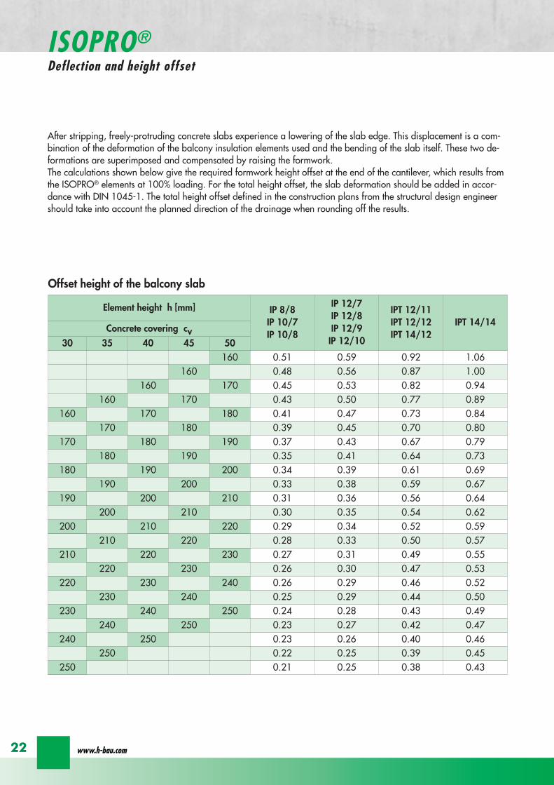
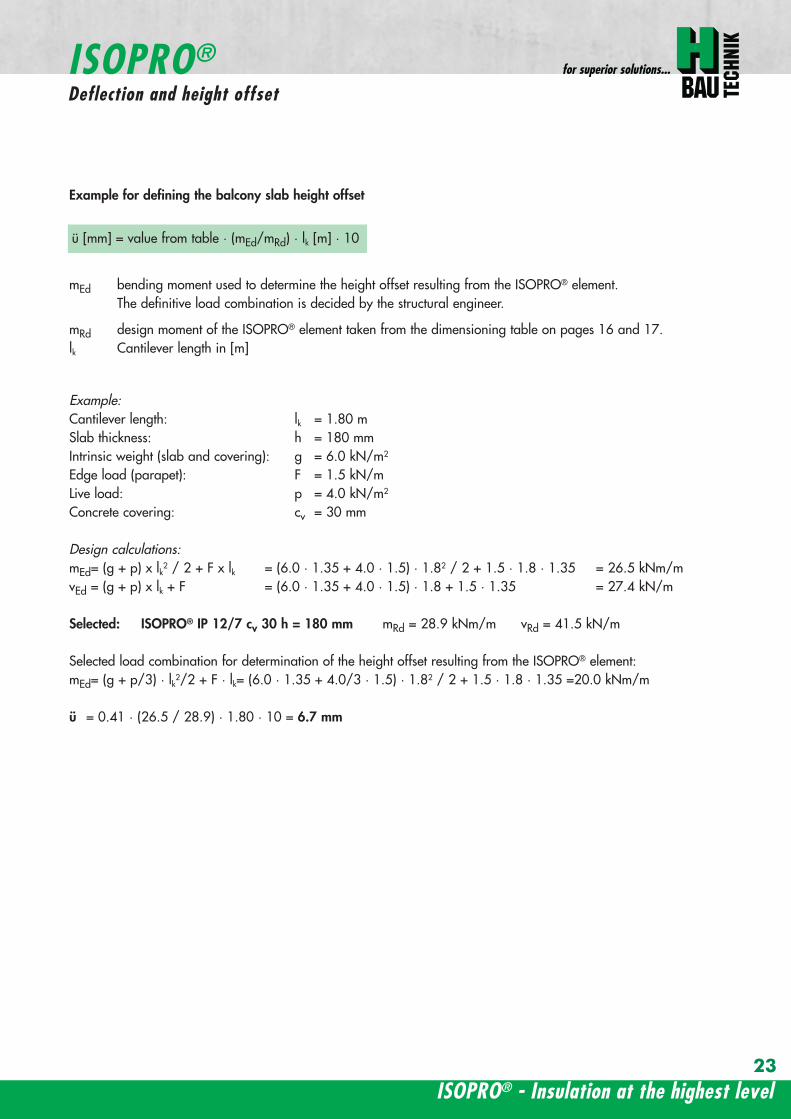
ISOPROreg - Insulation at the highest level
for superior solutionsISOPROreg
Deflection and height offset
Example for defining the balcony slab height offset
mEd bending moment used to determine the height offset resulting from the ISOPROreg elementThe definitive load combination is decided by the structural engineer
mRd design moment of the ISOPROreg element taken from the dimensioning table on pages 16 and 17lk Cantilever length in [m]
ExampleCantilever length lk = 180 mSlab thickness h = 180 mmIntrinsic weight (slab and covering) g = 60 kNm2
Edge load (parapet) F = 15 kNmLive load p = 40 kNm2
Concrete covering cv = 30 mm
Design calculationsmEd= (g + p) x lk2 2 + F x lk = (60 middot 135 + 40 middot 15) middot 182 2 + 15 middot 18 middot 135 = 265 kNmmvEd = (g + p) x lk + F = (60 middot 135 + 40 middot 15) middot 18 + 15 middot 135 = 274 kNm
Selected ISOPROreg IP 127 cv 30 h = 180 mm mRd = 289 kNmm vRd = 415 kNm
Selected load combination for determination of the height offset resulting from the ISOPROreg element mEd= (g + p3) middot lk22 + F middot lk= (60 middot 135 + 403 middot 15) middot 182 2 + 15 middot 18 middot 135 =200 kNmm
uuml = 041 middot (265 289) middot 180 middot 10 = 67 mm
23
uuml [mm] = value from table middot (mEdmRd) middot lk [m] middot 10
wwwh-baucom24
The external concrete components must have expansion joints at right angles to the insulation layer in order to limitthe stress caused by changes in temperature The spacing of the joints e is given in the following table
balcony
ISOPRO ISOPRO
expansion joint
balcony
e 2
e 2
ISOPRO Type IPT Corner
expansion joint
seperation ofexpansion joints e
seperation ofexpansion joints e
expansion jointExpansion joint spacing for ISOPROreg Types IP und IPT
Rod diameter [mm] le 10 12 14 16 20
Joint spacing e [m] 130 113 101 92 80
balcony
ISOPRO ISOPRO
expansion joint
balcony
e 2
e 2
ISOPRO Type IPT Corner
expansion joint
seperation ofexpansion joints e
seperation ofexpansion joints e
expansion joint
expansion joint dowellingeg HED-S + plastic sleeves
ISOPROreg
Expansion joint spacing
For corner constructions the maximum rod leg length is e2
ISOPROreg - Insulation at the highest level
for superior solutions
25
a a
b
c
b
c
sup3100
In pre-cast units
Arrange the lower reinforcement layer including themesh support as per structural design Distance to in-sulation joint le 100 mm (applies to IP only)
Install lower section The last transverse rod in themesh must be placed as close as possible to the insula-tion observing the required concrete covering
For IP the transverse force rod can be under or on topof the mesh The mesh support should be lifted until itis underneath the tension reinforcement
Concrete the slab element
Locate and fix the associated upper section andwhere required intermediate section
Type IP is supplied with suspension reinforcement asstandard
On-site
Lay the necessary on-site reinforcement on the floorside
Lay the slab element on the pre-prepared timberbeams
Lay the necessary on-site reinforcement on the bal-cony side
Attach the associated upper section and where re-quired intermediate section Bind the tension strutto the on-site reinforcement
h = 210 to 250 mm
Important note fit additional insertion stirrups Oslash 620 or stirrup meshQ188A on the balcony side
In type IP pre-cast units In type IPT pre-cast units
a a
b
c
b
c
sup3100
Type IP on-site Type IPT on-site
Important noteThe type identification for lower and upper sections must match (see also colour identification) The direction of in-stallation (on the balcony side) is mandatory
ISOPROreg
Two-part elements
wwwh-baucom26
upper section
centre section
lower section
upper section
centre section
lower section
balcony balconyslab slab
Type IP Type IPT
Construction
All ISOPROreg elements of types IP and IPT can be supplied as two-part elements
General notes
ndash The permitted resultant stresses can be found in thetables on pages 16 and 17 of this technical information
ndash Intermediate sections can be supplied for height offsetcompensation in 20 and 40 mm thicknesses
ndash Type IP If the mesh supports are placed with a spacingof le 100 mm from the insulation joint no additionalsuspension reinforcement is required Instead asuspension reinforcement dimensioned for VRd shouldbe located along the insulation joints
ndash For information regarding the required formwork height off-set and the maximum spacing of expansion joints refer topages 22 23 and 24
ndash The adhesive labels (type designation) for the upper andlower sections must be identical Follow the instructions forthe balcony side and the floor side
The following elements also have an addi-tional colour coding
ISOPROreg Type Colour code
IP 107 greenIP 127 blueIP 128 yellowIP 1210 white
The continuity of the colour coding throughthe elements ensures correct matching everytime even for short sections
ISOPROreg
Two-part elements
ISOPROreg - Insulation at the highest level
for superior solutions
27
balcony sidebalcony side
section 1st position
section 2nd position
slab balcony
1st position
2nd
posi
tion
cv
cvslab balcony
slab balcony
section 1st position
section 2nd position
1st position
2nd
posi
tion
slab balcony
IPT 127 Corner 820mmIPT 1210 Corner 960mm
IPT 127 Corner 820mmIPT 1210 Corner 960mm
IPT
127
Cor
ner
820m
mIP
T 12
10
Cor
ner
960m
mIP
T 12
7 C
orne
r82
0mm
IPT
121
0 C
orne
r96
0mm
General notes
Area of application for type IPT-Corner from slab thickness h le 180 mmOn-site reinforcement using overlap joints in accordance with DIN 1045-12001-07 Section 126Please refer to the information regarding on-site reinforcement on page 29Special elements for h = 160 mm are possibleBecause of the compression level a minimum spacing of the floor-side filigree slabs from the insulation body of185 mm is required for the ISOPROreg IPT-Corner elements
Type Length of element [m] Tension rods Compression level Transverse force rods
IPT 107-Corner 050 + 050 5 Oslash 10 + 5 Oslash 10 2 x 4 compression block 2 Oslash 10 + 2 Oslash 10
IPT 127-Corner 062 + 062 6 Oslash 12 + 6 Oslash 12 12 Oslash 14 + 12 Oslash 14 3 Oslash 10 + 3 Oslash 10
IPT 1210-Corner 062 + 062 6 Oslash 14 + 6 Oslash 14 14 Oslash 14 + 14 Oslash 14 3 Oslash 12 + 3 Oslash 12
Configuration of the elements
IPT 107-Corner
ISOPROreg Type IPT EckConstruction and dimensions
wwwh-baucom28
Plate thickness [mm] referred to cv [mm] Dimensional values for acceptable load moments MRd [kNm]
30 35 IPT 107 Corner IPT 127 Corner IPT 1210 Corner- 180 169 277 320
180 - 178 292 337- 190 186 306 354
190 - 195 320 370- 200 203 335 387
200 - 212 349 404- 210 220 363 421
210 - 229 378 437- 220 237 392 454
220 - 246 406 471- 230 254 421 487
230 - 263 435 504- 240 271 449 521
240 - 280 463 537- 250 289 478 554
250 - 297 492 571Dimensional values for acceptable transverse forces VRd [kN]
h = 180 - 250 [mm] 483 724 1043
balcony sidebalcony side
section 1st position
section 2nd position
slab balcony
1st position
2nd
posi
tion
cv
cvslab balcony
slab balcony
section 1st position
section 2nd position
1st position
2nd
posi
tion
slab balcony
IPT 127 Corner 820mmIPT 1210 Corner 960mm
IPT 127 Corner 820mmIPT 1210 Corner 960mm
IPT
127
Cor
ner
820m
mIP
T 12
10
Cor
ner
960m
mIP
T 12
7 C
orne
r82
0mm
IPT
121
0 C
orne
r96
0mm
Dimensioning table for concrete gege C2025
IPT 127-CornerIPT 1210-Corner
ISOPROreg Type IPT CornerConstruction and dimensions
ISOPROreg - Insulation at the highest level
for superior solutions
29
1st position
2nd
posi
tion
balcony slab
a
da
b b
c c
dstarter bar 1st position supplementary reinforcement
supplementary reinforcement
supp
lem
enta
ry r
einf
orce
men
t
supp
lem
enta
ry r
einf
orce
men
t
starter bar 1st position
stra
ter
bar
2nd
posi
tion
star
ter
bar
2nd
posi
tion
Type IPT 107-Corner IPT 127-Corner IPT 1210-Corner
starter bar 1st position 5 Oslash 10 6 Oslash 12 6 Oslash 14
starter bar 2nd position 5 Oslash 10 6 Oslash 12 6 Oslash 14
Supplementaryreinforcement 5 Oslash 10 6 Oslash 12 6 Oslash 14
Supplementaryreinforcement 5 Oslash 10 6 Oslash 12 6 Oslash 14
extension of the tension reinforcement internally as well as externally length = 2 x balcony cantilever length
ISOPROreg Type IPT CornerOn-site reinforcement
wwwh-baucom30
ISOPROreg - Insulation at the highest level
for superior solutions
IPQ IPQIPH
IPH
IPH
IPH
IPQS IPQSIPH IPQQS IPQQSIPH
IPQ IPQ
IPQ
IPQQ IPQQ
IPQQ IPQQIP
QS
IPQ IPQ
IPQ
Z
IPQ
S tie rod inlower position
IPQQ IPQQ
IPQ
Z
IPQ
S tie rod inlower position
propped balcony
internal-corner balcony with props
ISOPROreg
Examples of transverse force elements
propped balcony
propped balcony with selective point connection
internal-corner balcony with props
inset balcony with tieback3-sided overlying loggia with tieback
propped balcony with selective point connection
31
wwwh-baucom32
1000
1000
balcony slab balcony slab
IPQ 86 495 mmIPQ 88 495 mmIPQ 106 615 mmIPQ 126 740 mm
IPQ 86 495 mmIPQ 88 495 mmIPQ 106 615 mmIPQ 126 740 mm80
370 80 150
Calculated values for acceptable transverse forces vRd [kNm]
Element height IPQ 64 IPQ 65 IPQ 66 IPQ 68 IPQ 610
160 - 250 mm 348 435 522 695 869
Type IPQ 64 IPQ 65 IPQ 66 IPQ 68 IPQ 610Length [mm] 1000 1000 1000 1000 1000
Transverse force rods 4 Oslash 6 5 Oslash 6 6 Oslash 6 8 Oslash 6 10 Oslash 6
Compression blocks 4 4 4 4 4needed As [cmsup2] 08 10 12 16 20
Dimensioning table - Type IPQ for concrete gege C2025
Configuration of the elements Type IPQ
section
Top view
ISOPROreg Type IPQConstruction and dimensions
IPQ 64 - 610
min Element hight depentend on rod diameter Oslash 10 h ge170 Oslash 12 h ge180 Oslash 14 h ge190
ISOPROreg - Insulation at the highest level
for superior solutions
33
balcony slab
upper reinforcement of steel bars or mesh
lower reinforcement of steel bars or mesh
transverse shear force reinforcement 2 Oslash 8
insert stirrup
ls ls
a
b
c
d
d
a
c
d
b
suspension reinforcemente
ed
secondary reinforcement 2 Oslash 8
concrete concrete
The on-site suspension reinforcement pos and should be calculated for VRd (cf type test No 0519) and loca-ted next to the transverse force rods A Oslash 8 mm steel distribution rod should be installed above and below The sus-pension reinforcement can be replaced by a mesh support (see type IP page 18)DIN 1045-1 Section 1033 applies to the proof of the transverse force capacity of the slabs without shear reinforce-ment For proof of the transverse force capacity of the slabs with shear reinforcement DIN 1045-1 Section 1034 ap-plies The maximum transmissible transverse force across the joints must be limited to 03 VRdmax zu begrenzen
ISOPROreg Type IPQOn-site reinforcement
Calculated values for acceptable transverse forces vRd [kNm]
Element height IPQ 86 IPQ 88 IPQ 106 IPQ 125 IPQ 126
160 - 250 mm 927 1236 1449 1739 2089
Type IPQ 86 IPQ 88 IPQ 106 IPQ 125 IPQ 126Length [mm] 1000 1000 1000 1000 1000
Transverse force rods 6 Oslash 8 8 Oslash 8 6 Oslash 10 5 Oslash 12 6 Oslash 12
Compression blocks 4 4 4 4 4needed As [cmsup2] 21 28 33 40 48
Configuration of the elements Type IPQ
min Element hight depentend on rod diameter Oslash 10 h ge170 Oslash 12 h ge180 Oslash 14 h ge190
wwwh-baucom34
ISOPROreg Type IPQS 2Construction and dimensions
balcony slab
balcony slab
Calculated values for acceptable transverse forces VRd [kN]
Element height IPQS 62 IPQS 82 IPQS 102 IPQS 122 IPQS 142
160 - 250 mm 174 309 483 695 947
Dimensioning table - Type IPQS2 for concrete gege C2025
Type IPQS 62 IPQS 82 IPQS 102 IPQS 122 IPQS 142
Element length [mm] 300 300 300 300 300
Transverse force rods 2 Oslash 6 2 Oslash 8 2 Oslash 10 2 Oslash 12 2 Oslash 14
Compression rods 2 Oslash 10 2 Oslash 10 3 Oslash 10 4 Oslash 12 4 Oslash 14needed As [cmsup2] 040 071 111 160 218
Configuration of the elements Type IPQS2
min Element height dependent on rod diameter Oslash 10 h ge170 Oslash 12 h ge180 Oslash 14 h ge190
IPQS 82 495mmIPQS102 615mmIPQS122 740mmIPQS 142 860mm
IPQS 62
IPQS 82 495mmIPQS102 615mmIPQS122 740mmIPQS 142 860mm
ISOPROreg - Insulation at the highest level
for superior solutions
35
Calculated values for acceptable transverse forces VRd [kN]
Element height IPQS 63 IPQS 83 IPQS 103 IPQS 123 IPQS 143
160 - 250 mm 261 464 724 1043 1420
Dimensioning table - Type IPQS3 for concrete gege C2025
Type IPQS 63 IPQS 83 IPQS 103 IPQS 123 IPQS 143
Element length [mm] 400 400 400 400 400
Transverse force rods 3 Oslash 6 3 Oslash 8 3 Oslash 10 3 Oslash 12 3 Oslash 14
Compression rods 2 Oslash 10 3 Oslash 10 4 Oslash 12 5 Oslash 12 6 Oslash 14needed As [cmsup2] 060 107 167 240 327
Configuration of the elements Type IPQS3
balcony slab
balcony slab
ISOPROreg Type IPQS 3Construction and dimensionsn
IPQS 83 495mmIPQS103 615mmIPQS123 740mmIPQS 143 860mm
IPQS 63
IPQS 83 495mmIPQS103 615mmIPQS123 740mmIPQS 143 860mm
min Element height dependent on rod diameter Oslash 10 h ge170 Oslash 12 h ge180 Oslash 14 h ge190
wwwh-baucom36
ISOPROreg Type IPQQConstruction and dimensions
1000
1000
balcony balconyslab slab
180 80 150 80165 165
370 80 80150
IPQQ 86 495 mmIPQQ 106 615 mmIPQQ 126 740 mm
IPQQ 86 495 mmIPQQ 106 615 mmIPQQ 126 740 mm
IPQQ 64 IPQQ 66IPQQ 68 IPQQ 610
Calculated values for acceptable transverse forces vRd [kNm]
Element height IPQQ 64 IPQQ 66 IPQQ 68 IPQQ 610 IPQQ 86 IPQQ 106 IPQQ 126
160 - 250 mm plusmn348 plusmn522 plusmn695 plusmn869 plusmn927 plusmn1449 plusmn2086
Type IPQQ 64 IPQQ 66 IPQQ 68 IPQQ 610 IPQQ 86 IPQQ 106 IPQQ 126Element length [mm] 500 + 500 500 + 500 500 + 500 500 + 500 500 + 500 500 + 500 500 + 500Transverse force rods 2x4 Oslash 6 2x6 Oslash 6 2x8 Oslash 6 2x10 Oslash 6 2x6 Oslash 8 2x6 Oslash 10 2x6 Oslash 12
Compression rods 4 Oslash 10 4 Oslash 10 6 Oslash 10 6 Oslash 10 6 Oslash 10 10 Oslash 10 10 Oslash 12needed As [cmsup2] 080 120 160 200 213 333 480
Dimensioning table - Type IPQQ for concrete gege C2025
Configuration of the elements Typ IPQQ
Top view
Section
min Element height dependent on rod diameter Oslash 10 h ge170 Oslash 12 h ge180 Oslash 14 h ge190
ISOPROreg - Insulation at the highest level
for superior solutions
37
ISOPROreg Type IPQQOn-site reinforcement
balcony slab
upper reinforcement of steel bars or mesh
lower reinforcement of steel bars or mesh
ls ls
b
c
a
c
d
b
insert stirrupa
d
dinsert stirrupa
ad
d
secondary reinforcement 2 Oslash 8
concrete concrete
secondary reinforcement 2 Oslash 8
The on-site suspension reinforcement pos should be calculated for VRd and located next to the transverse forcerods A Oslash 8 mm steel distribution rod should be installed above and below DIN 1045-1 Section 1033 applies to the proof of the transverse force capacity of the slabs without shear reinforce-ment For proof of the transverse force capacity of the slabs with shear reinforcement DIN 1045-1 Section 1034 ap-plies The maximum transmissible transverse force across the joints must be limited to 03 VRdmax
wwwh-baucom38
ISOPROreg Type IPQQS 2Construction and dimensions
balcony slab
balcony slab
Calculated values for acceptable transverse forces VRd [kN]
Element height IPQQS 62 IPQQS 82 IPQQS 102 IPQQS 122 IPQQS 142
160 - 250 mm plusmn174 plusmn309 plusmn483 plusmn695 plusmn947
Dimensioning table - Type IPQQS2 for concrete gege C2025
Type IPQQS 62 IPQQS 82 IPQQS 102 IPQQS 122 IPQQS 142
Element length [mm] 300 300 300 300 300
Transverse force rods 2x 2 Oslash 6 2x 2 Oslash 8 2x 2 Oslash 10 2x 2 Oslash 12 2x 2 Oslash 14
Compression rods 2 Oslash 10 2 Oslash 10 3 Oslash 10 4 Oslash 12 4 Oslash 14needed As [cmsup2] 040 071 111 160 218
Configuration of the elements Type IPQQS2
IPQQS 82 495mmIPQQS 102 615mmIPQQS 122 740mmIPQQS 142 860mm
IPQQS 62
IPQQS 82 495mmIPQQS 102 615mmIPQQS 122 740mmIPQQS 142 860mm
min Element height dependent on rod diameter Oslash 10 h ge170 Oslash 12 h ge180 Oslash 14 h ge190
ISOPROreg - Insulation at the highest level
for superior solutions
39
ISOPROreg Type IPQQS 3Construction and dimensions
balcony slab
balcony slab
Calculated values for acceptable transverse forces VRd [kN]
Element height IPQQS 63 IPQQS 83 IPQQS 103 IPQQS 123 IPQQS 143
160 - 250 mm plusmn261 plusmn464 plusmn724 plusmn1043 plusmn1420
Dimensioning table - Type IPQQS3 for concrete gege C2025
Type IPQQS 63 IPQQS 83 IPQQS 103 IPQQS 123 IPQQS 143
Element length [mm] 400 400 400 400 400
Transverse force rods 2x 3 Oslash 6 2x 3 Oslash 8 2x 3 Oslash 10 2x 3 Oslash 12 2x 3 Oslash 14
Compression rods 2 Oslash 10 3 Oslash 10 4 Oslash 12 5 Oslash 12 6 Oslash 14needed As [cmsup2] 060 107 167 240 327
Configuration of the elements Type IPQQS3
min Element height dependent on rod diameter Oslash 10 h ge170 Oslash 12 h ge180 Oslash 14 h ge190 alternatively in Element length 500 mm available
IPQQS 83 495mmIPQQS 103 615mmIPQQS 123 740mmIPQQS 143 860mm
IPQQS 63
IPQQS 83 495mmIPQQS 103 615mmIPQQS 123 740mmIPQQS 143 860mm
wwwh-baucom40
ISOPROreg Type IPTDConstruction and dimensions
IPTD IPTD
inset balcony
30
balcony slab
Top view
Section
Example
Table of Dimensions ndash Type IPTD [length in mm]
TypeTension rod Transverse force rod Compression rod Supplemental transverse force
ZL QL DL Q10L Q12LIPTD 126 820 497 820 617 742IPTD 127 820 497 820 617 742IPTD 1210 820 497 820 617 742IPTD 1212 820 497 820 617 742IPTD 1410 960 497 960 617 742
ISOPROreg - Insulation at the highest level
for superior solutions
41
ISOPROreg Type IPTDOn-site reinforcement
balcony slab
upper reinforcement of steelbars or mesh
lower reinforcement of steelbars or mesh
secondary reinforcement 2 Oslash 8
secondary reinforcement 2 Oslash 8
insert stirrup
ls ls
AA
a
b
c
d
d
a
c
d
b
lower reinforcement of steelbars or meshc
upper reinforcement of steelbars or meshb
d
insert stirrupee
b
c
a
a
Section A - A
ISOPRO transverse force rods ISOPRO compression rods
ISOPRO transverse force rods ISOPRO tension rods
d
concrete concrete
The on-site suspension reinforcement pos should be calculated for VRd and located next to the transverse forcerods A Oslash 8 mm steel distribution rod should be installed above and below DIN 1045-1 Section 1033 applies to the proof of the transverse force capacity of the slabs without shear reinforce-ment For proof of the transverse force capacity of the slabs with shear reinforcement DIN 1045-1 Section 1034 ap-plies The maximum transmissible transverse force across the joints must be limited to 03 VRdmax
wwwh-baucom42
ISOPROreg Type IPTDDimensioning table for concrete gege C2025
Plate thickness [mm] withreference to cv [mm] Rated values for moment loading mRd [kNmm]
30 35 IPTD 126IPTD 126
Q10IPTD 126
Q12IPTD 127
IPTD 127Q10
IPTD 127Q12
IPTD 1210
- 160 plusmn 145 - - plusmn 182 - - plusmn 253160 - plusmn 154 - - plusmn 193 - - plusmn 269- 170 plusmn 162 plusmn 146 - plusmn 204 plusmn 187 - plusmn 284
170 - plusmn 171 plusmn 154 - plusmn 214 plusmn 197 - plusmn 299- 180 plusmn 180 plusmn 162 plusmn 145 plusmn 225 plusmn 208 plusmn 190 plusmn 314
180 - plusmn 189 plusmn 170 plusmn 152 plusmn 236 plusmn 218 plusmn 199 plusmn 330- 190 plusmn 197 plusmn 178 plusmn 159 plusmn 247 plusmn 228 plusmn 209 plusmn 345
190 - plusmn 206 plusmn 186 plusmn 166 plusmn 258 plusmn 238 plusmn 218 plusmn 360- 200 plusmn 215 plusmn 194 plusmn 173 plusmn 269 plusmn 248 plusmn 227 plusmn 375
200 - plusmn 223 plusmn 202 plusmn 180 plusmn 280 plusmn 258 plusmn 236 plusmn 391- 210 plusmn 232 plusmn 209 plusmn 187 plusmn 291 plusmn 268 plusmn 246 plusmn 406
210 - plusmn 241 plusmn 217 plusmn 194 plusmn 302 plusmn 278 plusmn 255 plusmn 421- 220 plusmn 250 plusmn 225 plusmn 201 plusmn 313 plusmn 288 plusmn 264 plusmn 437
220 - plusmn 258 plusmn 233 plusmn 208 plusmn 324 plusmn 298 plusmn 273 plusmn 452- 230 plusmn 267 plusmn 241 plusmn 215 plusmn 335 plusmn 308 plusmn 283 plusmn 467
230 - plusmn 276 plusmn 249 plusmn 222 plusmn 346 plusmn 318 plusmn 292 plusmn 482- 240 plusmn 285 plusmn 257 plusmn 229 plusmn 357 plusmn 328 plusmn 301 plusmn 498
240 - plusmn 293 plusmn 265 plusmn 236 plusmn 368 plusmn 339 plusmn 310 plusmn 513- 250 plusmn 302 plusmn 272 plusmn 243 plusmn 379 plusmn 349 plusmn 320 plusmn 528
250 - plusmn 311 plusmn 280 plusmn 250 plusmn 390 plusmn 359 plusmn 329 plusmn 543
Rated values for transverse force loading vRd [kNm]
h = 160 - 250 [mm ] plusmn 415 plusmn 762 plusmn 1098 plusmn 415 plusmn 762 plusmn 1098 plusmn 415
Type IPTD 126 IPTD 126Q10
IPTD 126Q12
IPTD 127 IPTD 127Q10
IPTD 127Q12
IPTD 1210
Element lenght [mm] 500 + 500 500 + 500 500 + 500 500 + 500 500 + 500 500 + 500 500 + 500
Tension rods 6 Oslash 12 6 Oslash 12 6 Oslash 122 Oslash 10 + 6 Oslash 12
2 Oslash 10 + 6 Oslash 12
2 Oslash 10 +6 Oslash 12
10 Oslash 12
Transverse forcerods
2x4 Oslash 8 2x4 Oslash 10 2x4 Oslash 12 2x4 Oslash 8 2x4 Oslash 10 2x4 Oslash 12 2x4 Oslash 8
Compression rods 6 Oslash 12 6 Oslash 12 6 Oslash 122 Oslash 10 + 6 Oslash 12
2 Oslash 10 +6 Oslash 12
2 Oslash 10 +6 Oslash 12
10 Oslash 12
Configuration of the elements Type IPTD
ISOPROreg - Insulation at the highest level
for superior solutions
43
ISOPROreg Type IPTDDimensioning table for concrete gege C2025
Rated values for moment loading mRd [kNmm]
IPTD 1210Q10
IPTD 1210Q12
IPTD 1212IPTD 1212
Q10IPTD 1212
Q12IPTD 1410
IPTD 1410Q10
IPTD 1410Q12
- - plusmn 307 - - plusmn 349 - -- - plusmn 326 - - plusmn 371 - -
plusmn 268 - plusmn 345 plusmn 328 - plusmn 392 plusmn 377 -plusmn 282 - plusmn 363 plusmn 346 - plusmn 414 plusmn 397 -plusmn 297 plusmn 279 plusmn 382 plusmn 364 plusmn 346 plusmn 436 plusmn 418 plusmn 401plusmn 311 plusmn 293 plusmn 400 plusmn 381 plusmn 363 plusmn- 457 plusmn 439 plusmn 421plusmn 325 plusmn 306 plusmn 419 plusmn 399 plusmn 380 plusmn 479 plusmn 459 plusmn 441plusmn 340 plusmn 320 plusmn 437 plusmn 417 plusmn 397 plusmn 500 plusmn 480 plusmn 461plusmn 354 plusmn 333 plusmn 456 plusmn 434 plusmn 414 plusmn 522 plusmn 501 plusmn 480plusmn 369 plusmn 347 plusmn 474 plusmn 452 plusmn 430 plusmn 543 plusmn 522 plusmn 500plusmn 383 plusmn 361 plusmn 493 plusmn 470 plusmn 447 plusmn 565 plusmn 542 plusmn 520plusmn 397 plusmn 374 plusmn 511 plusmn 487 plusmn 464 plusmn 587 plusmn 563 plusmn 540plusmn 412 plusmn 388 plusmn 530 plusmn 505 plusmn 481 plusmn 608 plusmn 584 plusmn 560plusmn 426 plusmn 401 plusmn 548 plusmn 523 plusmn 498 plusmn 630 plusmn 604 plusmn 580plusmn 440 plusmn 415 plusmn 567 plusmn 540 plusmn 515 plusmn 351 plusmn 625 plusmn 600plusmn 455 plusmn 428 plusmn 585 plusmn 558 plusmn 531 plusmn 673 plusmn 646 plusmn 619plusmn 469 plusmn 442 plusmn 604 plusmn 576 plusmn 548 plusmn 694 plusmn 666 plusmn 639plusmn 484 plusmn 455 plusmn 622 plusmn 593 plusmn 565 plusmn 716 plusmn 687 plusmn 659plusmn 498 plusmn 469 plusmn 641 plusmn 611 plusmn 582 plusmn 737 plusmn 708 plusmn 679plusmn 512 plusmn 483 plusmn 659 plusmn 629 plusmn 599 plusmn 759 plusmn 728 plusmn 699
Rated values for transverse force loading vRd [kNm]
plusmn 762 plusmn 1098 plusmn 415 plusmn 762 plusmn 1098 plusmn 415 plusmn 762 plusmn 1098
IPTD 1210Q10
IPTD 1210Q12
IPTD 1212 IPTD 1212Q10
IPTD 1212Q12
IPTD 1410 IPTD 1410Q10
IPTD 1410Q12
500 + 500 500 + 500 500 + 500 500 + 500 500 + 500 500 + 500 500 + 500 500 + 500
10 Oslash 12 10 Oslash 12 12 Oslash 12 12 Oslash 12 12 Oslash 12 10 Oslash 14 10 Oslash 14 10 Oslash 14
2x4 Oslash 10 2x4 Oslash 12 2x4 Oslash 8 2x4 Oslash 10 2x4 Oslash 12 2x4 Oslash 8 2x4 Oslash 10 2x4 Oslash 12
10 Oslash 12 10 Oslash 12 12 Oslash 12 12 Oslash 12 12 Oslash 12 10 Oslash 14 10 Oslash 14 10 Oslash 14
wwwh-baucom44
ISOPROreg Type IPQZConstruction and dimensions
300
40
0
300
40
0
balcony slab
balcony slab
For restraint-free support with an IPQZ element it should be opposed by an IPQS element Both elements should bereinforced by a tieback which corresponds in diameter and rod count to the IPQS and IPQZAn on-site stirrup reinforcement is required to connect IPQS to the floor
Calculated values for acceptable transverse forces VRd [kN]
Element height IPQZ 62 IPQZ 82 IPQZ 102 IPQZ 122 IPQZ 142
160 - 250 mm 174 309 483 695 947
IPQZ 63 IPQZ 83 IPQZ 103 IPQZ 123 IPQZ 143
160 - 250 mm 261 464 724 1043 1420
Dimensioning table ndash Type IPQZ for concrete ge C2025
Type IPQZ 62 IPQZ 82 IPQZ 102 IPQZ 122 IPQZ 142Element lenght [mm] 300 300 300 300 300
Transverse force rods 2 Oslash 6 2 Oslash 8 2 Oslash 10 2 Oslash 12 2 Oslash 14
Configuration of the elements
Type IPQZ 63 IPQZ 83 IPQZ 103 IPQZ 123 IPQZ 143Element length [mm] 400 400 400 400 400
Transverse force rods 3 Oslash 6 3 Oslash 8 3 Oslash 10 3 Oslash 12 3 Oslash 14
min Element height dependent on rod diameter Oslash 10 h ge170 Oslash 12 h ge180 Oslash 14 h ge190
IPQZ 82 83 495mmIPQZ102 103 615mmIPQZ122 123 740mmIPQZ 142 143 860mm
IPQZ 82 83 495mmIPQZ102 103 615mmIPQZ122 123 740mmIPQZ 142 143 860mm
IPQZ 62 63
ISOPROreg - Insulation at the highest level
for superior solutions
45
ISOPROreg Type IPQZOn-site reinforcement
Type Tieback Insert stirrup for use with
IPQZ 62 2 Oslash 6 1 Oslash 6 IPQS 62
IPQZ 82 2 Oslash 8 1 Oslash 8 IPQS 82
IPQZ 102 2 Oslash 10 1 Oslash 10 IPQS 102
IPQZ 122 2 Oslash 12 2 Oslash 8 IPQS 122
IPQZ 142 2 Oslash 14 2 Oslash 10 IPQS 142
tie roda
b
stirrup for anchering tie rodb
a
slab slabbalcony
Typ IPQZ Typ IPQS
Type Tieback Insert stirrup for use with
IPQZ 63 3 Oslash 6 2 Oslash 6 IPQS 63
IPQZ 83 3 Oslash 8 2 Oslash 8 IPQS 83
IPQZ 103 3 Oslash 10 2 Oslash 10 IPQS 103
IPQZ 123 3 Oslash 12 3 Oslash 8 IPQS 123
IPQZ 143 3 Oslash 14 3 Oslash 10 IPQS 143
wwwh-baucom46
ISOPROreg Type IPHConstruction and dimensions
The ISOPROreg elements type IPH which absorb horizontal forces must only be used with ISOPROreg cantilever slabs ortransverse force connections
The number of IPH elements to be used is defined by the structural engineer whereby the expansion joint spacing mustbe maintained
When using ISOPROreg IPH elements the force absorption of the line connection must be reduced by the ratio of thelength of the IPH elements to the total connection length as a percentage
independent of cvReinforcement Length of
element
HRd
Transverse force Horizontal Transverse force Horizontal
IPH 1 2 x 1 Oslash 8 - 100 mm plusmn 74 kN -IPH 2 - 1 Oslash 10 100 mm - plusmn181 kNIPH 3 2 x 1 Oslash 8 1 Oslash 10 100 mm plusmn 74 kN plusmn 181 kN
Dimensioning table ndash Type IPH for concrete gege C2025
balcony slab
balcony slab
balcony slab
balcony slab
balcony slab
balcony slab
100
100
100
250 80 250
250 80 250
250 80 250IPH 1 for absorption of horizontal forces parallel to the insulation joint
IPH 2 for absorption of horizontal forces perpendicular to the insulation joint
IPH 3 for absorption of horizontal forces parallel and perpendicular to the insulation joint
ISOPROreg - Insulation at the highest level
for superior solutions
47
ISOPROreg Type IPHOn-site reinforcement
The installation of the ISOPROreg IPH elements is analogous to the installation of the ISOPROreg cantilever slabs or trans-verse force connectionsThe number and positions of the elements are defined in the structural detail The elements must be fixed in their posi-tions
plate slab balcony slab
ls ls
lower reinforcement of steel bars or mesh
d
lower reinforcement of steel bars or mesh
upper reinforcement of steel bars or mesh
a
aa
dc
d
insert stirrup
a
b
c
secondary reinforcement Oslash 8
b
c c
insert stirrup
wwwh-baucom48
ISOPROreg Type IPAConstruction and calculation values
29
0204
0608
1012
1416
1820
2422
2628
0204
0608
1012
1416
1820
2224
2628
0 +10 +20 +30 +40 +50-10-20-30-40-50
dimensioning axis
MEd
VEd
NEd
380
60
gt160
sup3 16
0
130
Section
Mathematical model ndash Static system Interaction diagram
NRd [kN]
M Rd[kNm]
DimensionsLength of element 350 mmFascia thickness 160 ndash 240 mmHeight of element from 160 mmThickness of insulation element 60 mm
ReinforcementTension rods 3 Oslash 8Compression rods 3 Oslash 8Transverse force rods 2 x 2 Oslash 6
Calculated values for NRd = 0MRd 29 kNmelementVRd plusmn 127 kNelement
ISOPROreg - Insulation at the highest level
for superior solutions
49
ISOPROreg Type IPAOn-site reinforcement and installation instructions
400
100
aa
bc
b c
dd
e
f
gh
h
e
g
h
f
inse
rt s
tirru
ps
conn
ectio
n re
info
rcem
ent
conn
ectio
n re
info
rcem
ent
steel bar Oslash 8
upper slab reinforcement
insert stirrups 3 Oslash 8 150 mmsupplied
insert stirrup as constructive edging
lower slab reinforcement
34
160
56 59 60 60 59 56
34
Section Plan
Installation instructions1 Lay lower reinforcement including edging
2 Install ISOPROreg elements type IPA Spacing in accordance with static requirements
3 Install positions and and tie together
4 Lay upper floor reinforcement and tie together with the ISOPROreg reinforcement element
5 Concrete the floor slab Ensure safe positioning
6 Attach the on-site insulation between the ISOPROreg elements
7 Lay the fascia reinforcement and including edging and tie together with the ISOPROreg elements
supplied insulation
Type IPAType IPA
350e = separation of elements
gt 80
gt 16
0
Spacing of the elements Spacing of expansion joints
Expansion joint spacing e le 78 mAbove corner e2 le 35 m
The parapet must be verified as being a continuous supporte = spacing of the elements in accordance with static requirements
wwwh-baucom50
+5 +15 +25 +35-5-15-25-35
05
10
15
0
MEd
NEdVEd
MRdVRd
dimensioning axis
ISOPROreg Type IPFConstruction and calculation values
42034
0
60
100
Section
Mathematical model ndash Static system Interaction diagram
DimensionsLength of element 350 mmHeight of element from 160 mmThickness of insulation element 60 mm
ReinforcementTension rods 3 Oslash 6Compression rods 3 Oslash 6Transverse force rods 2 Oslash 6
Calculated values for NRd = 0MRd plusmn 15 kNmelementVRd + 127 kNelement
NRd [kN]
M Rd[kN
m]
VRd = 127 kN
ISOPROreg - Insulation at the highest level
for superior solutions
51
ISOPROreg Type IPFOn-site reinforcement and installation instructions
b
a insert stirrup min Oslash 6 150 mm
upper slab reinforcement
ac
b
e
d
c lower slab reinforcement
est
eel b
ar Oslash
8
d2
inse
rt s
tirru
p m
in Oslash
6
150
mm
3333
56 59 60 60 59 56
160
350
Section
Plan
Installation instructions1 Lay lower reinforcement including edging
2 Install ISOPROreg elements type IPA Spacing in accordance with static requirements
3 Install positions and and tie together
4 Lay upper floor reinforcement and tie together with the ISOPROreg reinforcement element
5 Concrete the floor slab Ensure safe positioning
6 Attach the on-site insulation between the ISOPROreg elements
7 Lay the fascia reinforcement and including edging and tie together with the ISOPROreg elements
350
60
Type IPF Type IPF
e = separation of elements
supplied insulation
parapet
Spacing of the elements
Spacing of expansion joints
Expansion joint spacing e le 78 mAbove corner e2 le 35 m
The parapet must be verified as beinga continuous support e = spacing of the elements in accor-dance with static requirements
wwwh-baucom52
ISOPROreg Type IPOConstruction and calculation values
23 lK
+PRd
+HEd
lK
sliding film
reinforcedconcrete console
soft-fibre panel
sup3 18
0
sup3 150 60
725
130 60 535
350
sliding film
reinforcedconcrete console
soft-fibre panelsup3
180
sup3 150 60
725
130 60 535
350
Section
Plan Mathematical modelStatic system
DimensionsLength of element 350 mmHeight of element from 180 mmThickness of insulation element 60 mm
ReinforcementTension rods 3 Oslash 6Compression rods 3 Oslash 8Transverse force rods 2 Oslash 10
for Hed = 0 PRd plusmn 171 kNmelement max HRd + 184 kNelement
0 2 4 6 8 10 12 14 16 20 22 Horizontal force HEd [kN]
25
15
10
5
0
P Rd[kN] concrete gege C2530
concrete gege C2025
PRd = 23
PRd = 10
HEd
= 18
4
HEd
= 23
1
ISOPROreg - Insulation at the highest level
for superior solutions
53
ISOPROreg Type IPOOn-site reinforcement and installation instructions
slab
a
a
bde
b
c
c upper reinforcement of steel bars or mesh
lower reinforcement of steel bars or mesh
insert stirrupde
long
itudi
nal r
einf
orce
men
t
clos
ed s
tirru
p
concrete
concrete
Section Installation instructions
1 Lay lower reinforcement including edging
2 Install ISOPROreg elements type IPO Spacingin accordance with static requirements
3 Lay upper floor reinforcement and tie to-gether with the ISOPROreg reinforcement ele-ment
4 Attach the on-site insulation between the ISO-PROreg elements
5 Lay the console reinforcement and andtie together with the ISOPROreg elements Thefloor edge beam must be designed as a con-tinuous support
6 As far as practical the console and the floorshould be concreted simultaneously Ensuresecure positioning
reinforced concrete joist
ISOPRO Type IPO ISOPRO Type IPO
supplied insulation
e = separation of elements350
Spacing of the elements Spacing of expansion joints
Expansion joint spacing e le 78 mAbove corner e2 le 35 m
The parapet must be verified as being a continuous support e = spacing of the elements in accordance with static requirements
wwwh-baucom54
ISOPROreg Type IPSConstruction and calculation values
80
5050
80 ZL
balcony slab plate slab
wall
console
tension rod
transverse force bars
compression strut
ZL
QL
QL
DL
80
DL
100100
BSt 500 Nr Wst Nr 14571
BSt 500 Nr Wst Nr 14571
BSt 500 S
BSt 500 S
Section
80
5050
80 ZL
balcony slab plate slab
wall
console
tension rod
transverse force bars
compression strut
ZL
QL
QL
DL
80
DL
100100
BSt 500 Nr Wst Nr 14571
BSt 500 Nr Wst Nr 14571
BSt 500 S
BSt 500 S
Dimensions - Type IPS [length in mm]
Type Tension rod Transverse forcerod
Compressionrod
ZL QL DLIPS 1 690 500 430IPS 2 820 620 500IPS 3 960 745 570IPS 4 1550 865 600
Dimensioning table for concrete gege C2025Element hight 400 mm IPS 1 IPS 2 IPS 3 IPS 4
moment MRd [kNm] 221 294 375 624
transverse forces VRd [kN] 213 333 480 653
Type IPS 1 IPS 2 IPS 3 IPS 4
Element width [mm] 220 220 220 220
Tension rods 3 Oslash 10 3 Oslash 12 3 Oslash 14 4 Oslash 14
Transverse force rods 2 Oslash 8 2 Oslash 10 2 Oslash 12 2 Oslash 14
Compression rods 3 Oslash 12 3 Oslash 14 3 Oslash 16 3 Oslash 20
Other designs and dimensions are available on requestThe bonding area I underlies the determination of the anchoring lengths However if required the reinforcement rods can also be designed for bonding area II
Configuration of the elements
ISOPROreg - Insulation at the highest level
for superior solutions
55
ISOPROreg Type IPSOn-site reinforcement and installation instructions
wall plate reinforcement to structural calculations
tension rod
transverse force bars
compression strut
a
b
c
d
d
a
b
a closed stirrup
edging
c suspension reinforcementconcrete concrete
Installation instructions
1 Lay wall plate reinforcement to meet structural requirements2 Insert ISOPROreg element type IPS and tie together with the wall
reinforcement Transverse reinforcement in overlap zone in accordance with DIN 1045-1
3 Install and tie together beam reinforcement and according to structural calculations Pos edging in accordance withDIN 1045-1 Pos installed as a closed stirrup to avoid shearing
4 When concreting make sure that both sides are uniformly filled and compacted
5 Formwork offset for the beam in accordance with structural calculations
wall plate reinforcement to structural calculations
tension rod
transverse force bars
compression strut
a
b
c
d
d
a
b
a closed stirrup
edging
c suspension reinforcementconcrete concrete
80
b b
plate slab
Type IPS
wal
l pla
te
Type IPS wal
l pla
te
balcony slab
supplied insulation
Configuration of the elements Expansion joint spacing
TypeJoint spacing [m]
e
IPS 1 113
IPS 2 101
IPS 3 92
IPS 4 80
For corner constructions the maximumrod leg length is e2
wwwh-baucom56
ISOPROreg Type IPWConstruction and calculation values
ZL ZL80
420 420
QL QL
DL DL
290290
low
er s
ectio
n12
50ce
ntre
sec
tion
uppe
r se
ctio
n25
0
h =
150
- 3
50
m
80
balcony
balcony slab
slab
exte
rnal
wal
l
inte
rnal
wal
l
horizontal transverse force bars
horizontal transverse force bars
upper section bht in mm150-250 250 80
lower section bht in mm150-250 1250 80
Section
Table of Dimensions Type IPW [length in mm]
Type
Tension rod Transverseforce rod
Compressionrod
ZL QL DLIPW 1 600 423 270IPW 2 790 563 335IPW 3 980 653 410IPW 4 1170 783 470
Element width b = 150 ndash 250 mmElement height h = 150 ndash 350 mInsulation material thickness t = 80 mm
Dimensioning table for concrete gege C2025Calculated values for acceptable moments MRdy [kNm]
Element height [m] IPW 1 IPW 2 IPW 3 IPW 415 ndash 20 537 918 1169 154420 ndash 25 737 1267 1614 2132
gt 25 937 1616 2059 2720Calculated values for acceptable transverse forces [kN]
vRdz [kN] 412 622 1066 1535vRdy [kN] plusmn137 plusmn137 plusmn137 plusmn137
Type IPW 1 IPW 2 IPW 3 IPW 4Element height [m] ge150 ge150 ge150 ge150Tension rods 4 Oslash 6 4 Oslash 8 4 Oslash 10 4 Oslash 12Transverse force rods Qz 6 Oslash 6 6 Oslash 8 6 Oslash 10 6 Oslash 12Transverse force rods Qy 2 x 2 Oslash 6 2 x 2 Oslash 6 2 x 2 Oslash 6 2 x 2 Oslash 6Compression rods 6 Oslash 8 6 Oslash 10 6 Oslash 12 6 Oslash 14
Configuration of the elements
Moment effects from wind loading are absorbed bythe stiffening effect of the balcony slab
MRdz = 0
Bonding area II underlies the determination of theoverlap lengths On request the anchoring lengthscan also be dimensioned for bonding area I Designsand dimensions deviating from the standard ele-ments are available on request
ISOPROreg - Insulation at the highest level
for superior solutions
57
ISOPROreg Type IPWOn-site reinforcement and installation instructions
MRdz
VRdz VRdy
x
z
y
MRdy
Mathematical model ndash Static system
balcony slab
balcony slab
steel
mes
h re
info
rcem
ent
a
steel
mes
h re
info
rcem
ent
b
e connection reinforcementto structural calculations
f
insert stirrupas constructive edging c
c
d steel bar min 2 Oslash 8
concrete sup3 2025
exte
rnal
wal
l
inte
rnal
wal
l
insert stirrupas constructive edging
connection reinforcementto structural calculations
a bc c
d
d
steel bar min 2 Oslash 8
steel bar min 2 Oslash 8
insert stirrupinsert stirrupsteel mesh reinforcement steel mesh reinforcement
80
wall p
late
wall p
late
balcony slab
plate slab
Type IPWsupplied insulation
Type IPW
b b
e e e
Configuration of the elements
Installation instructions
1 Position internal wall reinforcement 2 Attach the constructive edging inter-
nally (insert stirrup)3 Starting at the bottom assemble the in-
dividual ISOPROreg elements type IPWand tie together with the wall reinforce-ment
4 Erect and internally and tie to-gether
5 Position the external wall reinforce-ments and in accordancewith structural design and tie to theISOPROreg elements
6 When concreting pay particular atten-tion to the positional security of the ele-ments It is recommended to fill andcompact both wall plates at the sametime
wwwh-baucom58
ISOPROreg
Approvals and Type testing
Approvals
ISOPRO Type IP Z-157-244ISOPRO Type IPT Z-157-243
Type testing
ISOPRO Type IP Test No 0517ISOPRO Type IPT Test No 0518ISOPRO Type IPQ Test No 0519
ISOPROreg - Insulation at the highest level
for superior solutions
59
ISOPROreg
Tender
___________________________________________________________________________
Scope Application area DIN 276013 Concrete and reinforced concrete Floor constructions
Structural installations__________________________________________________________________________________
ISOPROreg supporting and thermally insulating connection elements
01 supporting the balcony slab using ISOPROreg elements from H-BAU Technik GmbH02 required for installation03 m Type IP cv = mm h = mm04 m Type IPQ cv = mm h = mm05 part Type cv = mm h = mm
Special fabrication according to the following description
06 for thermal separation of the concrete07 for the storey floors pos 08 for the roofing pos 09 for 10 and11 for the balcony slap pos 12 for the loggia slab pos 13 for the cantilever slab pos 14 for the 15 in fire protection construction class F9016 the bonding is made in the reinforcement of pos and pos 17 deliver18 deliver install and bond with the connection reinforcement19 only install and bond with the connection reinforcement delivery provided20 the installation is made in accordance with instructions from
H-BAU Technik GmbHAm Guumlterbahnhof 2079771 Klettgau-ErzingenGermanyTel +49 (0) 77 42 92 15-20Fax +49 (0) 77 42 92 15-90
21 in accordance with the detail and reinforcement drawings no 22 material 23 wages 24 unit price
25 total price
wwwh-baucom60
NOTES
ISOPROreg - Insulation at the highest level
for superior solutions
61
NOTES
wwwh-baucom
Concreting with system
ISOPROreg
KESIIRAPIDOBATreg
JSDHEDFERBOXreg
BOXFERreg
GRIPRIPreg
PENTAFLEXreg
RIPINOXreg
WARMBORDreg
SCHALBORDreg
ZEMBORDreg
SCHALL-ISO ACCESSORIES
H-BAU Technik GmbHAm Guumlterbahnhof 20D-79771 Klettgau-ErzingenTel + 49 (0) 7742 92 15-20Fax + 49 (0) 7742 92 15-90infoklettgauh-baude
Produktion Nord-OstBrandenburger StraszligeD-14641 WachowTel + 49 (0) 3 3239 775-20Fax + 49 (0) 3 3239 775-90infoberlinh-baude
Balcony insulation elementsLifting anchorsShuttering tubesPush-in pegsReinforcement connectorsReinforcement connectorsMasonry connectorsSealing technologyRustproof stainless steelStop end panelsStop end panelsStop end panelsSound insulation elementsSpacers
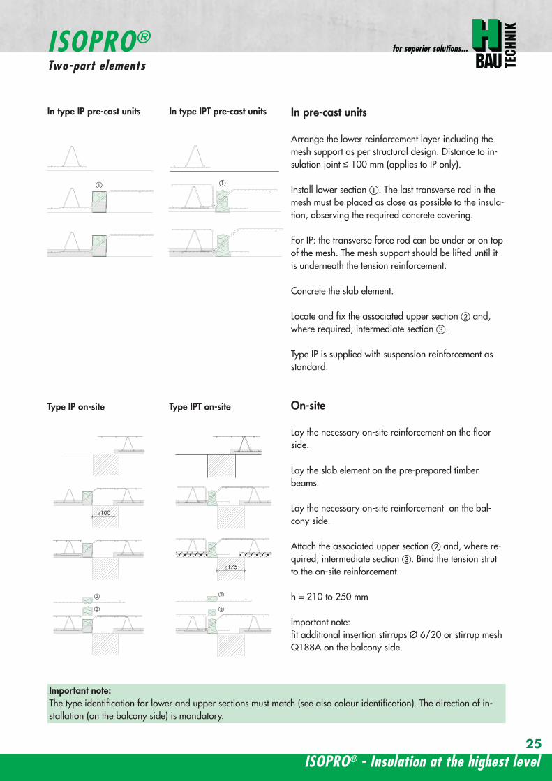
ISOPROreg - Insulation at the highest level
for superior solutions
25
a a
b
c
b
c
sup3100
In pre-cast units
Arrange the lower reinforcement layer including themesh support as per structural design Distance to in-sulation joint le 100 mm (applies to IP only)
Install lower section The last transverse rod in themesh must be placed as close as possible to the insula-tion observing the required concrete covering
For IP the transverse force rod can be under or on topof the mesh The mesh support should be lifted until itis underneath the tension reinforcement
Concrete the slab element
Locate and fix the associated upper section andwhere required intermediate section
Type IP is supplied with suspension reinforcement asstandard
On-site
Lay the necessary on-site reinforcement on the floorside
Lay the slab element on the pre-prepared timberbeams
Lay the necessary on-site reinforcement on the bal-cony side
Attach the associated upper section and where re-quired intermediate section Bind the tension strutto the on-site reinforcement
h = 210 to 250 mm
Important note fit additional insertion stirrups Oslash 620 or stirrup meshQ188A on the balcony side
In type IP pre-cast units In type IPT pre-cast units
a a
b
c
b
c
sup3100
Type IP on-site Type IPT on-site
Important noteThe type identification for lower and upper sections must match (see also colour identification) The direction of in-stallation (on the balcony side) is mandatory
ISOPROreg
Two-part elements
wwwh-baucom26
upper section
centre section
lower section
upper section
centre section
lower section
balcony balconyslab slab
Type IP Type IPT
Construction
All ISOPROreg elements of types IP and IPT can be supplied as two-part elements
General notes
ndash The permitted resultant stresses can be found in thetables on pages 16 and 17 of this technical information
ndash Intermediate sections can be supplied for height offsetcompensation in 20 and 40 mm thicknesses
ndash Type IP If the mesh supports are placed with a spacingof le 100 mm from the insulation joint no additionalsuspension reinforcement is required Instead asuspension reinforcement dimensioned for VRd shouldbe located along the insulation joints
ndash For information regarding the required formwork height off-set and the maximum spacing of expansion joints refer topages 22 23 and 24
ndash The adhesive labels (type designation) for the upper andlower sections must be identical Follow the instructions forthe balcony side and the floor side
The following elements also have an addi-tional colour coding
ISOPROreg Type Colour code
IP 107 greenIP 127 blueIP 128 yellowIP 1210 white
The continuity of the colour coding throughthe elements ensures correct matching everytime even for short sections
ISOPROreg
Two-part elements
ISOPROreg - Insulation at the highest level
for superior solutions
27
balcony sidebalcony side
section 1st position
section 2nd position
slab balcony
1st position
2nd
posi
tion
cv
cvslab balcony
slab balcony
section 1st position
section 2nd position
1st position
2nd
posi
tion
slab balcony
IPT 127 Corner 820mmIPT 1210 Corner 960mm
IPT 127 Corner 820mmIPT 1210 Corner 960mm
IPT
127
Cor
ner
820m
mIP
T 12
10
Cor
ner
960m
mIP
T 12
7 C
orne
r82
0mm
IPT
121
0 C
orne
r96
0mm
General notes
Area of application for type IPT-Corner from slab thickness h le 180 mmOn-site reinforcement using overlap joints in accordance with DIN 1045-12001-07 Section 126Please refer to the information regarding on-site reinforcement on page 29Special elements for h = 160 mm are possibleBecause of the compression level a minimum spacing of the floor-side filigree slabs from the insulation body of185 mm is required for the ISOPROreg IPT-Corner elements
Type Length of element [m] Tension rods Compression level Transverse force rods
IPT 107-Corner 050 + 050 5 Oslash 10 + 5 Oslash 10 2 x 4 compression block 2 Oslash 10 + 2 Oslash 10
IPT 127-Corner 062 + 062 6 Oslash 12 + 6 Oslash 12 12 Oslash 14 + 12 Oslash 14 3 Oslash 10 + 3 Oslash 10
IPT 1210-Corner 062 + 062 6 Oslash 14 + 6 Oslash 14 14 Oslash 14 + 14 Oslash 14 3 Oslash 12 + 3 Oslash 12
Configuration of the elements
IPT 107-Corner
ISOPROreg Type IPT EckConstruction and dimensions
wwwh-baucom28
Plate thickness [mm] referred to cv [mm] Dimensional values for acceptable load moments MRd [kNm]
30 35 IPT 107 Corner IPT 127 Corner IPT 1210 Corner- 180 169 277 320
180 - 178 292 337- 190 186 306 354
190 - 195 320 370- 200 203 335 387
200 - 212 349 404- 210 220 363 421
210 - 229 378 437- 220 237 392 454
220 - 246 406 471- 230 254 421 487
230 - 263 435 504- 240 271 449 521
240 - 280 463 537- 250 289 478 554
250 - 297 492 571Dimensional values for acceptable transverse forces VRd [kN]
h = 180 - 250 [mm] 483 724 1043
balcony sidebalcony side
section 1st position
section 2nd position
slab balcony
1st position
2nd
posi
tion
cv
cvslab balcony
slab balcony
section 1st position
section 2nd position
1st position
2nd
posi
tion
slab balcony
IPT 127 Corner 820mmIPT 1210 Corner 960mm
IPT 127 Corner 820mmIPT 1210 Corner 960mm
IPT
127
Cor
ner
820m
mIP
T 12
10
Cor
ner
960m
mIP
T 12
7 C
orne
r82
0mm
IPT
121
0 C
orne
r96
0mm
Dimensioning table for concrete gege C2025
IPT 127-CornerIPT 1210-Corner
ISOPROreg Type IPT CornerConstruction and dimensions
ISOPROreg - Insulation at the highest level
for superior solutions
29
1st position
2nd
posi
tion
balcony slab
a
da
b b
c c
dstarter bar 1st position supplementary reinforcement
supplementary reinforcement
supp
lem
enta
ry r
einf
orce
men
t
supp
lem
enta
ry r
einf
orce
men
t
starter bar 1st position
stra
ter
bar
2nd
posi
tion
star
ter
bar
2nd
posi
tion
Type IPT 107-Corner IPT 127-Corner IPT 1210-Corner
starter bar 1st position 5 Oslash 10 6 Oslash 12 6 Oslash 14
starter bar 2nd position 5 Oslash 10 6 Oslash 12 6 Oslash 14
Supplementaryreinforcement 5 Oslash 10 6 Oslash 12 6 Oslash 14
Supplementaryreinforcement 5 Oslash 10 6 Oslash 12 6 Oslash 14
extension of the tension reinforcement internally as well as externally length = 2 x balcony cantilever length
ISOPROreg Type IPT CornerOn-site reinforcement
wwwh-baucom30
ISOPROreg - Insulation at the highest level
for superior solutions
IPQ IPQIPH
IPH
IPH
IPH
IPQS IPQSIPH IPQQS IPQQSIPH
IPQ IPQ
IPQ
IPQQ IPQQ
IPQQ IPQQIP
QS
IPQ IPQ
IPQ
Z
IPQ
S tie rod inlower position
IPQQ IPQQ
IPQ
Z
IPQ
S tie rod inlower position
propped balcony
internal-corner balcony with props
ISOPROreg
Examples of transverse force elements
propped balcony
propped balcony with selective point connection
internal-corner balcony with props
inset balcony with tieback3-sided overlying loggia with tieback
propped balcony with selective point connection
31
wwwh-baucom32
1000
1000
balcony slab balcony slab
IPQ 86 495 mmIPQ 88 495 mmIPQ 106 615 mmIPQ 126 740 mm
IPQ 86 495 mmIPQ 88 495 mmIPQ 106 615 mmIPQ 126 740 mm80
370 80 150
Calculated values for acceptable transverse forces vRd [kNm]
Element height IPQ 64 IPQ 65 IPQ 66 IPQ 68 IPQ 610
160 - 250 mm 348 435 522 695 869
Type IPQ 64 IPQ 65 IPQ 66 IPQ 68 IPQ 610Length [mm] 1000 1000 1000 1000 1000
Transverse force rods 4 Oslash 6 5 Oslash 6 6 Oslash 6 8 Oslash 6 10 Oslash 6
Compression blocks 4 4 4 4 4needed As [cmsup2] 08 10 12 16 20
Dimensioning table - Type IPQ for concrete gege C2025
Configuration of the elements Type IPQ
section
Top view
ISOPROreg Type IPQConstruction and dimensions
IPQ 64 - 610
min Element hight depentend on rod diameter Oslash 10 h ge170 Oslash 12 h ge180 Oslash 14 h ge190
ISOPROreg - Insulation at the highest level
for superior solutions
33
balcony slab
upper reinforcement of steel bars or mesh
lower reinforcement of steel bars or mesh
transverse shear force reinforcement 2 Oslash 8
insert stirrup
ls ls
a
b
c
d
d
a
c
d
b
suspension reinforcemente
ed
secondary reinforcement 2 Oslash 8
concrete concrete
The on-site suspension reinforcement pos and should be calculated for VRd (cf type test No 0519) and loca-ted next to the transverse force rods A Oslash 8 mm steel distribution rod should be installed above and below The sus-pension reinforcement can be replaced by a mesh support (see type IP page 18)DIN 1045-1 Section 1033 applies to the proof of the transverse force capacity of the slabs without shear reinforce-ment For proof of the transverse force capacity of the slabs with shear reinforcement DIN 1045-1 Section 1034 ap-plies The maximum transmissible transverse force across the joints must be limited to 03 VRdmax zu begrenzen
ISOPROreg Type IPQOn-site reinforcement
Calculated values for acceptable transverse forces vRd [kNm]
Element height IPQ 86 IPQ 88 IPQ 106 IPQ 125 IPQ 126
160 - 250 mm 927 1236 1449 1739 2089
Type IPQ 86 IPQ 88 IPQ 106 IPQ 125 IPQ 126Length [mm] 1000 1000 1000 1000 1000
Transverse force rods 6 Oslash 8 8 Oslash 8 6 Oslash 10 5 Oslash 12 6 Oslash 12
Compression blocks 4 4 4 4 4needed As [cmsup2] 21 28 33 40 48
Configuration of the elements Type IPQ
min Element hight depentend on rod diameter Oslash 10 h ge170 Oslash 12 h ge180 Oslash 14 h ge190
wwwh-baucom34
ISOPROreg Type IPQS 2Construction and dimensions
balcony slab
balcony slab
Calculated values for acceptable transverse forces VRd [kN]
Element height IPQS 62 IPQS 82 IPQS 102 IPQS 122 IPQS 142
160 - 250 mm 174 309 483 695 947
Dimensioning table - Type IPQS2 for concrete gege C2025
Type IPQS 62 IPQS 82 IPQS 102 IPQS 122 IPQS 142
Element length [mm] 300 300 300 300 300
Transverse force rods 2 Oslash 6 2 Oslash 8 2 Oslash 10 2 Oslash 12 2 Oslash 14
Compression rods 2 Oslash 10 2 Oslash 10 3 Oslash 10 4 Oslash 12 4 Oslash 14needed As [cmsup2] 040 071 111 160 218
Configuration of the elements Type IPQS2
min Element height dependent on rod diameter Oslash 10 h ge170 Oslash 12 h ge180 Oslash 14 h ge190
IPQS 82 495mmIPQS102 615mmIPQS122 740mmIPQS 142 860mm
IPQS 62
IPQS 82 495mmIPQS102 615mmIPQS122 740mmIPQS 142 860mm
ISOPROreg - Insulation at the highest level
for superior solutions
35
Calculated values for acceptable transverse forces VRd [kN]
Element height IPQS 63 IPQS 83 IPQS 103 IPQS 123 IPQS 143
160 - 250 mm 261 464 724 1043 1420
Dimensioning table - Type IPQS3 for concrete gege C2025
Type IPQS 63 IPQS 83 IPQS 103 IPQS 123 IPQS 143
Element length [mm] 400 400 400 400 400
Transverse force rods 3 Oslash 6 3 Oslash 8 3 Oslash 10 3 Oslash 12 3 Oslash 14
Compression rods 2 Oslash 10 3 Oslash 10 4 Oslash 12 5 Oslash 12 6 Oslash 14needed As [cmsup2] 060 107 167 240 327
Configuration of the elements Type IPQS3
balcony slab
balcony slab
ISOPROreg Type IPQS 3Construction and dimensionsn
IPQS 83 495mmIPQS103 615mmIPQS123 740mmIPQS 143 860mm
IPQS 63
IPQS 83 495mmIPQS103 615mmIPQS123 740mmIPQS 143 860mm
min Element height dependent on rod diameter Oslash 10 h ge170 Oslash 12 h ge180 Oslash 14 h ge190
wwwh-baucom36
ISOPROreg Type IPQQConstruction and dimensions
1000
1000
balcony balconyslab slab
180 80 150 80165 165
370 80 80150
IPQQ 86 495 mmIPQQ 106 615 mmIPQQ 126 740 mm
IPQQ 86 495 mmIPQQ 106 615 mmIPQQ 126 740 mm
IPQQ 64 IPQQ 66IPQQ 68 IPQQ 610
Calculated values for acceptable transverse forces vRd [kNm]
Element height IPQQ 64 IPQQ 66 IPQQ 68 IPQQ 610 IPQQ 86 IPQQ 106 IPQQ 126
160 - 250 mm plusmn348 plusmn522 plusmn695 plusmn869 plusmn927 plusmn1449 plusmn2086
Type IPQQ 64 IPQQ 66 IPQQ 68 IPQQ 610 IPQQ 86 IPQQ 106 IPQQ 126Element length [mm] 500 + 500 500 + 500 500 + 500 500 + 500 500 + 500 500 + 500 500 + 500Transverse force rods 2x4 Oslash 6 2x6 Oslash 6 2x8 Oslash 6 2x10 Oslash 6 2x6 Oslash 8 2x6 Oslash 10 2x6 Oslash 12
Compression rods 4 Oslash 10 4 Oslash 10 6 Oslash 10 6 Oslash 10 6 Oslash 10 10 Oslash 10 10 Oslash 12needed As [cmsup2] 080 120 160 200 213 333 480
Dimensioning table - Type IPQQ for concrete gege C2025
Configuration of the elements Typ IPQQ
Top view
Section
min Element height dependent on rod diameter Oslash 10 h ge170 Oslash 12 h ge180 Oslash 14 h ge190
ISOPROreg - Insulation at the highest level
for superior solutions
37
ISOPROreg Type IPQQOn-site reinforcement
balcony slab
upper reinforcement of steel bars or mesh
lower reinforcement of steel bars or mesh
ls ls
b
c
a
c
d
b
insert stirrupa
d
dinsert stirrupa
ad
d
secondary reinforcement 2 Oslash 8
concrete concrete
secondary reinforcement 2 Oslash 8
The on-site suspension reinforcement pos should be calculated for VRd and located next to the transverse forcerods A Oslash 8 mm steel distribution rod should be installed above and below DIN 1045-1 Section 1033 applies to the proof of the transverse force capacity of the slabs without shear reinforce-ment For proof of the transverse force capacity of the slabs with shear reinforcement DIN 1045-1 Section 1034 ap-plies The maximum transmissible transverse force across the joints must be limited to 03 VRdmax
wwwh-baucom38
ISOPROreg Type IPQQS 2Construction and dimensions
balcony slab
balcony slab
Calculated values for acceptable transverse forces VRd [kN]
Element height IPQQS 62 IPQQS 82 IPQQS 102 IPQQS 122 IPQQS 142
160 - 250 mm plusmn174 plusmn309 plusmn483 plusmn695 plusmn947
Dimensioning table - Type IPQQS2 for concrete gege C2025
Type IPQQS 62 IPQQS 82 IPQQS 102 IPQQS 122 IPQQS 142
Element length [mm] 300 300 300 300 300
Transverse force rods 2x 2 Oslash 6 2x 2 Oslash 8 2x 2 Oslash 10 2x 2 Oslash 12 2x 2 Oslash 14
Compression rods 2 Oslash 10 2 Oslash 10 3 Oslash 10 4 Oslash 12 4 Oslash 14needed As [cmsup2] 040 071 111 160 218
Configuration of the elements Type IPQQS2
IPQQS 82 495mmIPQQS 102 615mmIPQQS 122 740mmIPQQS 142 860mm
IPQQS 62
IPQQS 82 495mmIPQQS 102 615mmIPQQS 122 740mmIPQQS 142 860mm
min Element height dependent on rod diameter Oslash 10 h ge170 Oslash 12 h ge180 Oslash 14 h ge190
ISOPROreg - Insulation at the highest level
for superior solutions
39
ISOPROreg Type IPQQS 3Construction and dimensions
balcony slab
balcony slab
Calculated values for acceptable transverse forces VRd [kN]
Element height IPQQS 63 IPQQS 83 IPQQS 103 IPQQS 123 IPQQS 143
160 - 250 mm plusmn261 plusmn464 plusmn724 plusmn1043 plusmn1420
Dimensioning table - Type IPQQS3 for concrete gege C2025
Type IPQQS 63 IPQQS 83 IPQQS 103 IPQQS 123 IPQQS 143
Element length [mm] 400 400 400 400 400
Transverse force rods 2x 3 Oslash 6 2x 3 Oslash 8 2x 3 Oslash 10 2x 3 Oslash 12 2x 3 Oslash 14
Compression rods 2 Oslash 10 3 Oslash 10 4 Oslash 12 5 Oslash 12 6 Oslash 14needed As [cmsup2] 060 107 167 240 327
Configuration of the elements Type IPQQS3
min Element height dependent on rod diameter Oslash 10 h ge170 Oslash 12 h ge180 Oslash 14 h ge190 alternatively in Element length 500 mm available
IPQQS 83 495mmIPQQS 103 615mmIPQQS 123 740mmIPQQS 143 860mm
IPQQS 63
IPQQS 83 495mmIPQQS 103 615mmIPQQS 123 740mmIPQQS 143 860mm
wwwh-baucom40
ISOPROreg Type IPTDConstruction and dimensions
IPTD IPTD
inset balcony
30
balcony slab
Top view
Section
Example
Table of Dimensions ndash Type IPTD [length in mm]
TypeTension rod Transverse force rod Compression rod Supplemental transverse force
ZL QL DL Q10L Q12LIPTD 126 820 497 820 617 742IPTD 127 820 497 820 617 742IPTD 1210 820 497 820 617 742IPTD 1212 820 497 820 617 742IPTD 1410 960 497 960 617 742
ISOPROreg - Insulation at the highest level
for superior solutions
41
ISOPROreg Type IPTDOn-site reinforcement
balcony slab
upper reinforcement of steelbars or mesh
lower reinforcement of steelbars or mesh
secondary reinforcement 2 Oslash 8
secondary reinforcement 2 Oslash 8
insert stirrup
ls ls
AA
a
b
c
d
d
a
c
d
b
lower reinforcement of steelbars or meshc
upper reinforcement of steelbars or meshb
d
insert stirrupee
b
c
a
a
Section A - A
ISOPRO transverse force rods ISOPRO compression rods
ISOPRO transverse force rods ISOPRO tension rods
d
concrete concrete
The on-site suspension reinforcement pos should be calculated for VRd and located next to the transverse forcerods A Oslash 8 mm steel distribution rod should be installed above and below DIN 1045-1 Section 1033 applies to the proof of the transverse force capacity of the slabs without shear reinforce-ment For proof of the transverse force capacity of the slabs with shear reinforcement DIN 1045-1 Section 1034 ap-plies The maximum transmissible transverse force across the joints must be limited to 03 VRdmax
wwwh-baucom42
ISOPROreg Type IPTDDimensioning table for concrete gege C2025
Plate thickness [mm] withreference to cv [mm] Rated values for moment loading mRd [kNmm]
30 35 IPTD 126IPTD 126
Q10IPTD 126
Q12IPTD 127
IPTD 127Q10
IPTD 127Q12
IPTD 1210
- 160 plusmn 145 - - plusmn 182 - - plusmn 253160 - plusmn 154 - - plusmn 193 - - plusmn 269- 170 plusmn 162 plusmn 146 - plusmn 204 plusmn 187 - plusmn 284
170 - plusmn 171 plusmn 154 - plusmn 214 plusmn 197 - plusmn 299- 180 plusmn 180 plusmn 162 plusmn 145 plusmn 225 plusmn 208 plusmn 190 plusmn 314
180 - plusmn 189 plusmn 170 plusmn 152 plusmn 236 plusmn 218 plusmn 199 plusmn 330- 190 plusmn 197 plusmn 178 plusmn 159 plusmn 247 plusmn 228 plusmn 209 plusmn 345
190 - plusmn 206 plusmn 186 plusmn 166 plusmn 258 plusmn 238 plusmn 218 plusmn 360- 200 plusmn 215 plusmn 194 plusmn 173 plusmn 269 plusmn 248 plusmn 227 plusmn 375
200 - plusmn 223 plusmn 202 plusmn 180 plusmn 280 plusmn 258 plusmn 236 plusmn 391- 210 plusmn 232 plusmn 209 plusmn 187 plusmn 291 plusmn 268 plusmn 246 plusmn 406
210 - plusmn 241 plusmn 217 plusmn 194 plusmn 302 plusmn 278 plusmn 255 plusmn 421- 220 plusmn 250 plusmn 225 plusmn 201 plusmn 313 plusmn 288 plusmn 264 plusmn 437
220 - plusmn 258 plusmn 233 plusmn 208 plusmn 324 plusmn 298 plusmn 273 plusmn 452- 230 plusmn 267 plusmn 241 plusmn 215 plusmn 335 plusmn 308 plusmn 283 plusmn 467
230 - plusmn 276 plusmn 249 plusmn 222 plusmn 346 plusmn 318 plusmn 292 plusmn 482- 240 plusmn 285 plusmn 257 plusmn 229 plusmn 357 plusmn 328 plusmn 301 plusmn 498
240 - plusmn 293 plusmn 265 plusmn 236 plusmn 368 plusmn 339 plusmn 310 plusmn 513- 250 plusmn 302 plusmn 272 plusmn 243 plusmn 379 plusmn 349 plusmn 320 plusmn 528
250 - plusmn 311 plusmn 280 plusmn 250 plusmn 390 plusmn 359 plusmn 329 plusmn 543
Rated values for transverse force loading vRd [kNm]
h = 160 - 250 [mm ] plusmn 415 plusmn 762 plusmn 1098 plusmn 415 plusmn 762 plusmn 1098 plusmn 415
Type IPTD 126 IPTD 126Q10
IPTD 126Q12
IPTD 127 IPTD 127Q10
IPTD 127Q12
IPTD 1210
Element lenght [mm] 500 + 500 500 + 500 500 + 500 500 + 500 500 + 500 500 + 500 500 + 500
Tension rods 6 Oslash 12 6 Oslash 12 6 Oslash 122 Oslash 10 + 6 Oslash 12
2 Oslash 10 + 6 Oslash 12
2 Oslash 10 +6 Oslash 12
10 Oslash 12
Transverse forcerods
2x4 Oslash 8 2x4 Oslash 10 2x4 Oslash 12 2x4 Oslash 8 2x4 Oslash 10 2x4 Oslash 12 2x4 Oslash 8
Compression rods 6 Oslash 12 6 Oslash 12 6 Oslash 122 Oslash 10 + 6 Oslash 12
2 Oslash 10 +6 Oslash 12
2 Oslash 10 +6 Oslash 12
10 Oslash 12
Configuration of the elements Type IPTD
ISOPROreg - Insulation at the highest level
for superior solutions
43
ISOPROreg Type IPTDDimensioning table for concrete gege C2025
Rated values for moment loading mRd [kNmm]
IPTD 1210Q10
IPTD 1210Q12
IPTD 1212IPTD 1212
Q10IPTD 1212
Q12IPTD 1410
IPTD 1410Q10
IPTD 1410Q12
- - plusmn 307 - - plusmn 349 - -- - plusmn 326 - - plusmn 371 - -
plusmn 268 - plusmn 345 plusmn 328 - plusmn 392 plusmn 377 -plusmn 282 - plusmn 363 plusmn 346 - plusmn 414 plusmn 397 -plusmn 297 plusmn 279 plusmn 382 plusmn 364 plusmn 346 plusmn 436 plusmn 418 plusmn 401plusmn 311 plusmn 293 plusmn 400 plusmn 381 plusmn 363 plusmn- 457 plusmn 439 plusmn 421plusmn 325 plusmn 306 plusmn 419 plusmn 399 plusmn 380 plusmn 479 plusmn 459 plusmn 441plusmn 340 plusmn 320 plusmn 437 plusmn 417 plusmn 397 plusmn 500 plusmn 480 plusmn 461plusmn 354 plusmn 333 plusmn 456 plusmn 434 plusmn 414 plusmn 522 plusmn 501 plusmn 480plusmn 369 plusmn 347 plusmn 474 plusmn 452 plusmn 430 plusmn 543 plusmn 522 plusmn 500plusmn 383 plusmn 361 plusmn 493 plusmn 470 plusmn 447 plusmn 565 plusmn 542 plusmn 520plusmn 397 plusmn 374 plusmn 511 plusmn 487 plusmn 464 plusmn 587 plusmn 563 plusmn 540plusmn 412 plusmn 388 plusmn 530 plusmn 505 plusmn 481 plusmn 608 plusmn 584 plusmn 560plusmn 426 plusmn 401 plusmn 548 plusmn 523 plusmn 498 plusmn 630 plusmn 604 plusmn 580plusmn 440 plusmn 415 plusmn 567 plusmn 540 plusmn 515 plusmn 351 plusmn 625 plusmn 600plusmn 455 plusmn 428 plusmn 585 plusmn 558 plusmn 531 plusmn 673 plusmn 646 plusmn 619plusmn 469 plusmn 442 plusmn 604 plusmn 576 plusmn 548 plusmn 694 plusmn 666 plusmn 639plusmn 484 plusmn 455 plusmn 622 plusmn 593 plusmn 565 plusmn 716 plusmn 687 plusmn 659plusmn 498 plusmn 469 plusmn 641 plusmn 611 plusmn 582 plusmn 737 plusmn 708 plusmn 679plusmn 512 plusmn 483 plusmn 659 plusmn 629 plusmn 599 plusmn 759 plusmn 728 plusmn 699
Rated values for transverse force loading vRd [kNm]
plusmn 762 plusmn 1098 plusmn 415 plusmn 762 plusmn 1098 plusmn 415 plusmn 762 plusmn 1098
IPTD 1210Q10
IPTD 1210Q12
IPTD 1212 IPTD 1212Q10
IPTD 1212Q12
IPTD 1410 IPTD 1410Q10
IPTD 1410Q12
500 + 500 500 + 500 500 + 500 500 + 500 500 + 500 500 + 500 500 + 500 500 + 500
10 Oslash 12 10 Oslash 12 12 Oslash 12 12 Oslash 12 12 Oslash 12 10 Oslash 14 10 Oslash 14 10 Oslash 14
2x4 Oslash 10 2x4 Oslash 12 2x4 Oslash 8 2x4 Oslash 10 2x4 Oslash 12 2x4 Oslash 8 2x4 Oslash 10 2x4 Oslash 12
10 Oslash 12 10 Oslash 12 12 Oslash 12 12 Oslash 12 12 Oslash 12 10 Oslash 14 10 Oslash 14 10 Oslash 14
wwwh-baucom44
ISOPROreg Type IPQZConstruction and dimensions
300
40
0
300
40
0
balcony slab
balcony slab
For restraint-free support with an IPQZ element it should be opposed by an IPQS element Both elements should bereinforced by a tieback which corresponds in diameter and rod count to the IPQS and IPQZAn on-site stirrup reinforcement is required to connect IPQS to the floor
Calculated values for acceptable transverse forces VRd [kN]
Element height IPQZ 62 IPQZ 82 IPQZ 102 IPQZ 122 IPQZ 142
160 - 250 mm 174 309 483 695 947
IPQZ 63 IPQZ 83 IPQZ 103 IPQZ 123 IPQZ 143
160 - 250 mm 261 464 724 1043 1420
Dimensioning table ndash Type IPQZ for concrete ge C2025
Type IPQZ 62 IPQZ 82 IPQZ 102 IPQZ 122 IPQZ 142Element lenght [mm] 300 300 300 300 300
Transverse force rods 2 Oslash 6 2 Oslash 8 2 Oslash 10 2 Oslash 12 2 Oslash 14
Configuration of the elements
Type IPQZ 63 IPQZ 83 IPQZ 103 IPQZ 123 IPQZ 143Element length [mm] 400 400 400 400 400
Transverse force rods 3 Oslash 6 3 Oslash 8 3 Oslash 10 3 Oslash 12 3 Oslash 14
min Element height dependent on rod diameter Oslash 10 h ge170 Oslash 12 h ge180 Oslash 14 h ge190
IPQZ 82 83 495mmIPQZ102 103 615mmIPQZ122 123 740mmIPQZ 142 143 860mm
IPQZ 82 83 495mmIPQZ102 103 615mmIPQZ122 123 740mmIPQZ 142 143 860mm
IPQZ 62 63
ISOPROreg - Insulation at the highest level
for superior solutions
45
ISOPROreg Type IPQZOn-site reinforcement
Type Tieback Insert stirrup for use with
IPQZ 62 2 Oslash 6 1 Oslash 6 IPQS 62
IPQZ 82 2 Oslash 8 1 Oslash 8 IPQS 82
IPQZ 102 2 Oslash 10 1 Oslash 10 IPQS 102
IPQZ 122 2 Oslash 12 2 Oslash 8 IPQS 122
IPQZ 142 2 Oslash 14 2 Oslash 10 IPQS 142
tie roda
b
stirrup for anchering tie rodb
a
slab slabbalcony
Typ IPQZ Typ IPQS
Type Tieback Insert stirrup for use with
IPQZ 63 3 Oslash 6 2 Oslash 6 IPQS 63
IPQZ 83 3 Oslash 8 2 Oslash 8 IPQS 83
IPQZ 103 3 Oslash 10 2 Oslash 10 IPQS 103
IPQZ 123 3 Oslash 12 3 Oslash 8 IPQS 123
IPQZ 143 3 Oslash 14 3 Oslash 10 IPQS 143
wwwh-baucom46
ISOPROreg Type IPHConstruction and dimensions
The ISOPROreg elements type IPH which absorb horizontal forces must only be used with ISOPROreg cantilever slabs ortransverse force connections
The number of IPH elements to be used is defined by the structural engineer whereby the expansion joint spacing mustbe maintained
When using ISOPROreg IPH elements the force absorption of the line connection must be reduced by the ratio of thelength of the IPH elements to the total connection length as a percentage
independent of cvReinforcement Length of
element
HRd
Transverse force Horizontal Transverse force Horizontal
IPH 1 2 x 1 Oslash 8 - 100 mm plusmn 74 kN -IPH 2 - 1 Oslash 10 100 mm - plusmn181 kNIPH 3 2 x 1 Oslash 8 1 Oslash 10 100 mm plusmn 74 kN plusmn 181 kN
Dimensioning table ndash Type IPH for concrete gege C2025
balcony slab
balcony slab
balcony slab
balcony slab
balcony slab
balcony slab
100
100
100
250 80 250
250 80 250
250 80 250IPH 1 for absorption of horizontal forces parallel to the insulation joint
IPH 2 for absorption of horizontal forces perpendicular to the insulation joint
IPH 3 for absorption of horizontal forces parallel and perpendicular to the insulation joint
ISOPROreg - Insulation at the highest level
for superior solutions
47
ISOPROreg Type IPHOn-site reinforcement
The installation of the ISOPROreg IPH elements is analogous to the installation of the ISOPROreg cantilever slabs or trans-verse force connectionsThe number and positions of the elements are defined in the structural detail The elements must be fixed in their posi-tions
plate slab balcony slab
ls ls
lower reinforcement of steel bars or mesh
d
lower reinforcement of steel bars or mesh
upper reinforcement of steel bars or mesh
a
aa
dc
d
insert stirrup
a
b
c
secondary reinforcement Oslash 8
b
c c
insert stirrup
wwwh-baucom48
ISOPROreg Type IPAConstruction and calculation values
29
0204
0608
1012
1416
1820
2422
2628
0204
0608
1012
1416
1820
2224
2628
0 +10 +20 +30 +40 +50-10-20-30-40-50
dimensioning axis
MEd
VEd
NEd
380
60
gt160
sup3 16
0
130
Section
Mathematical model ndash Static system Interaction diagram
NRd [kN]
M Rd[kNm]
DimensionsLength of element 350 mmFascia thickness 160 ndash 240 mmHeight of element from 160 mmThickness of insulation element 60 mm
ReinforcementTension rods 3 Oslash 8Compression rods 3 Oslash 8Transverse force rods 2 x 2 Oslash 6
Calculated values for NRd = 0MRd 29 kNmelementVRd plusmn 127 kNelement
ISOPROreg - Insulation at the highest level
for superior solutions
49
ISOPROreg Type IPAOn-site reinforcement and installation instructions
400
100
aa
bc
b c
dd
e
f
gh
h
e
g
h
f
inse
rt s
tirru
ps
conn
ectio
n re
info
rcem
ent
conn
ectio
n re
info
rcem
ent
steel bar Oslash 8
upper slab reinforcement
insert stirrups 3 Oslash 8 150 mmsupplied
insert stirrup as constructive edging
lower slab reinforcement
34
160
56 59 60 60 59 56
34
Section Plan
Installation instructions1 Lay lower reinforcement including edging
2 Install ISOPROreg elements type IPA Spacing in accordance with static requirements
3 Install positions and and tie together
4 Lay upper floor reinforcement and tie together with the ISOPROreg reinforcement element
5 Concrete the floor slab Ensure safe positioning
6 Attach the on-site insulation between the ISOPROreg elements
7 Lay the fascia reinforcement and including edging and tie together with the ISOPROreg elements
supplied insulation
Type IPAType IPA
350e = separation of elements
gt 80
gt 16
0
Spacing of the elements Spacing of expansion joints
Expansion joint spacing e le 78 mAbove corner e2 le 35 m
The parapet must be verified as being a continuous supporte = spacing of the elements in accordance with static requirements
wwwh-baucom50
+5 +15 +25 +35-5-15-25-35
05
10
15
0
MEd
NEdVEd
MRdVRd
dimensioning axis
ISOPROreg Type IPFConstruction and calculation values
42034
0
60
100
Section
Mathematical model ndash Static system Interaction diagram
DimensionsLength of element 350 mmHeight of element from 160 mmThickness of insulation element 60 mm
ReinforcementTension rods 3 Oslash 6Compression rods 3 Oslash 6Transverse force rods 2 Oslash 6
Calculated values for NRd = 0MRd plusmn 15 kNmelementVRd + 127 kNelement
NRd [kN]
M Rd[kN
m]
VRd = 127 kN
ISOPROreg - Insulation at the highest level
for superior solutions
51
ISOPROreg Type IPFOn-site reinforcement and installation instructions
b
a insert stirrup min Oslash 6 150 mm
upper slab reinforcement
ac
b
e
d
c lower slab reinforcement
est
eel b
ar Oslash
8
d2
inse
rt s
tirru
p m
in Oslash
6
150
mm
3333
56 59 60 60 59 56
160
350
Section
Plan
Installation instructions1 Lay lower reinforcement including edging
2 Install ISOPROreg elements type IPA Spacing in accordance with static requirements
3 Install positions and and tie together
4 Lay upper floor reinforcement and tie together with the ISOPROreg reinforcement element
5 Concrete the floor slab Ensure safe positioning
6 Attach the on-site insulation between the ISOPROreg elements
7 Lay the fascia reinforcement and including edging and tie together with the ISOPROreg elements
350
60
Type IPF Type IPF
e = separation of elements
supplied insulation
parapet
Spacing of the elements
Spacing of expansion joints
Expansion joint spacing e le 78 mAbove corner e2 le 35 m
The parapet must be verified as beinga continuous support e = spacing of the elements in accor-dance with static requirements
wwwh-baucom52
ISOPROreg Type IPOConstruction and calculation values
23 lK
+PRd
+HEd
lK
sliding film
reinforcedconcrete console
soft-fibre panel
sup3 18
0
sup3 150 60
725
130 60 535
350
sliding film
reinforcedconcrete console
soft-fibre panelsup3
180
sup3 150 60
725
130 60 535
350
Section
Plan Mathematical modelStatic system
DimensionsLength of element 350 mmHeight of element from 180 mmThickness of insulation element 60 mm
ReinforcementTension rods 3 Oslash 6Compression rods 3 Oslash 8Transverse force rods 2 Oslash 10
for Hed = 0 PRd plusmn 171 kNmelement max HRd + 184 kNelement
0 2 4 6 8 10 12 14 16 20 22 Horizontal force HEd [kN]
25
15
10
5
0
P Rd[kN] concrete gege C2530
concrete gege C2025
PRd = 23
PRd = 10
HEd
= 18
4
HEd
= 23
1
ISOPROreg - Insulation at the highest level
for superior solutions
53
ISOPROreg Type IPOOn-site reinforcement and installation instructions
slab
a
a
bde
b
c
c upper reinforcement of steel bars or mesh
lower reinforcement of steel bars or mesh
insert stirrupde
long
itudi
nal r
einf
orce
men
t
clos
ed s
tirru
p
concrete
concrete
Section Installation instructions
1 Lay lower reinforcement including edging
2 Install ISOPROreg elements type IPO Spacingin accordance with static requirements
3 Lay upper floor reinforcement and tie to-gether with the ISOPROreg reinforcement ele-ment
4 Attach the on-site insulation between the ISO-PROreg elements
5 Lay the console reinforcement and andtie together with the ISOPROreg elements Thefloor edge beam must be designed as a con-tinuous support
6 As far as practical the console and the floorshould be concreted simultaneously Ensuresecure positioning
reinforced concrete joist
ISOPRO Type IPO ISOPRO Type IPO
supplied insulation
e = separation of elements350
Spacing of the elements Spacing of expansion joints
Expansion joint spacing e le 78 mAbove corner e2 le 35 m
The parapet must be verified as being a continuous support e = spacing of the elements in accordance with static requirements
wwwh-baucom54
ISOPROreg Type IPSConstruction and calculation values
80
5050
80 ZL
balcony slab plate slab
wall
console
tension rod
transverse force bars
compression strut
ZL
QL
QL
DL
80
DL
100100
BSt 500 Nr Wst Nr 14571
BSt 500 Nr Wst Nr 14571
BSt 500 S
BSt 500 S
Section
80
5050
80 ZL
balcony slab plate slab
wall
console
tension rod
transverse force bars
compression strut
ZL
QL
QL
DL
80
DL
100100
BSt 500 Nr Wst Nr 14571
BSt 500 Nr Wst Nr 14571
BSt 500 S
BSt 500 S
Dimensions - Type IPS [length in mm]
Type Tension rod Transverse forcerod
Compressionrod
ZL QL DLIPS 1 690 500 430IPS 2 820 620 500IPS 3 960 745 570IPS 4 1550 865 600
Dimensioning table for concrete gege C2025Element hight 400 mm IPS 1 IPS 2 IPS 3 IPS 4
moment MRd [kNm] 221 294 375 624
transverse forces VRd [kN] 213 333 480 653
Type IPS 1 IPS 2 IPS 3 IPS 4
Element width [mm] 220 220 220 220
Tension rods 3 Oslash 10 3 Oslash 12 3 Oslash 14 4 Oslash 14
Transverse force rods 2 Oslash 8 2 Oslash 10 2 Oslash 12 2 Oslash 14
Compression rods 3 Oslash 12 3 Oslash 14 3 Oslash 16 3 Oslash 20
Other designs and dimensions are available on requestThe bonding area I underlies the determination of the anchoring lengths However if required the reinforcement rods can also be designed for bonding area II
Configuration of the elements
ISOPROreg - Insulation at the highest level
for superior solutions
55
ISOPROreg Type IPSOn-site reinforcement and installation instructions
wall plate reinforcement to structural calculations
tension rod
transverse force bars
compression strut
a
b
c
d
d
a
b
a closed stirrup
edging
c suspension reinforcementconcrete concrete
Installation instructions
1 Lay wall plate reinforcement to meet structural requirements2 Insert ISOPROreg element type IPS and tie together with the wall
reinforcement Transverse reinforcement in overlap zone in accordance with DIN 1045-1
3 Install and tie together beam reinforcement and according to structural calculations Pos edging in accordance withDIN 1045-1 Pos installed as a closed stirrup to avoid shearing
4 When concreting make sure that both sides are uniformly filled and compacted
5 Formwork offset for the beam in accordance with structural calculations
wall plate reinforcement to structural calculations
tension rod
transverse force bars
compression strut
a
b
c
d
d
a
b
a closed stirrup
edging
c suspension reinforcementconcrete concrete
80
b b
plate slab
Type IPS
wal
l pla
te
Type IPS wal
l pla
te
balcony slab
supplied insulation
Configuration of the elements Expansion joint spacing
TypeJoint spacing [m]
e
IPS 1 113
IPS 2 101
IPS 3 92
IPS 4 80
For corner constructions the maximumrod leg length is e2
wwwh-baucom56
ISOPROreg Type IPWConstruction and calculation values
ZL ZL80
420 420
QL QL
DL DL
290290
low
er s
ectio
n12
50ce
ntre
sec
tion
uppe
r se
ctio
n25
0
h =
150
- 3
50
m
80
balcony
balcony slab
slab
exte
rnal
wal
l
inte
rnal
wal
l
horizontal transverse force bars
horizontal transverse force bars
upper section bht in mm150-250 250 80
lower section bht in mm150-250 1250 80
Section
Table of Dimensions Type IPW [length in mm]
Type
Tension rod Transverseforce rod
Compressionrod
ZL QL DLIPW 1 600 423 270IPW 2 790 563 335IPW 3 980 653 410IPW 4 1170 783 470
Element width b = 150 ndash 250 mmElement height h = 150 ndash 350 mInsulation material thickness t = 80 mm
Dimensioning table for concrete gege C2025Calculated values for acceptable moments MRdy [kNm]
Element height [m] IPW 1 IPW 2 IPW 3 IPW 415 ndash 20 537 918 1169 154420 ndash 25 737 1267 1614 2132
gt 25 937 1616 2059 2720Calculated values for acceptable transverse forces [kN]
vRdz [kN] 412 622 1066 1535vRdy [kN] plusmn137 plusmn137 plusmn137 plusmn137
Type IPW 1 IPW 2 IPW 3 IPW 4Element height [m] ge150 ge150 ge150 ge150Tension rods 4 Oslash 6 4 Oslash 8 4 Oslash 10 4 Oslash 12Transverse force rods Qz 6 Oslash 6 6 Oslash 8 6 Oslash 10 6 Oslash 12Transverse force rods Qy 2 x 2 Oslash 6 2 x 2 Oslash 6 2 x 2 Oslash 6 2 x 2 Oslash 6Compression rods 6 Oslash 8 6 Oslash 10 6 Oslash 12 6 Oslash 14
Configuration of the elements
Moment effects from wind loading are absorbed bythe stiffening effect of the balcony slab
MRdz = 0
Bonding area II underlies the determination of theoverlap lengths On request the anchoring lengthscan also be dimensioned for bonding area I Designsand dimensions deviating from the standard ele-ments are available on request
ISOPROreg - Insulation at the highest level
for superior solutions
57
ISOPROreg Type IPWOn-site reinforcement and installation instructions
MRdz
VRdz VRdy
x
z
y
MRdy
Mathematical model ndash Static system
balcony slab
balcony slab
steel
mes
h re
info
rcem
ent
a
steel
mes
h re
info
rcem
ent
b
e connection reinforcementto structural calculations
f
insert stirrupas constructive edging c
c
d steel bar min 2 Oslash 8
concrete sup3 2025
exte
rnal
wal
l
inte
rnal
wal
l
insert stirrupas constructive edging
connection reinforcementto structural calculations
a bc c
d
d
steel bar min 2 Oslash 8
steel bar min 2 Oslash 8
insert stirrupinsert stirrupsteel mesh reinforcement steel mesh reinforcement
80
wall p
late
wall p
late
balcony slab
plate slab
Type IPWsupplied insulation
Type IPW
b b
e e e
Configuration of the elements
Installation instructions
1 Position internal wall reinforcement 2 Attach the constructive edging inter-
nally (insert stirrup)3 Starting at the bottom assemble the in-
dividual ISOPROreg elements type IPWand tie together with the wall reinforce-ment
4 Erect and internally and tie to-gether
5 Position the external wall reinforce-ments and in accordancewith structural design and tie to theISOPROreg elements
6 When concreting pay particular atten-tion to the positional security of the ele-ments It is recommended to fill andcompact both wall plates at the sametime
wwwh-baucom58
ISOPROreg
Approvals and Type testing
Approvals
ISOPRO Type IP Z-157-244ISOPRO Type IPT Z-157-243
Type testing
ISOPRO Type IP Test No 0517ISOPRO Type IPT Test No 0518ISOPRO Type IPQ Test No 0519
ISOPROreg - Insulation at the highest level
for superior solutions
59
ISOPROreg
Tender
___________________________________________________________________________
Scope Application area DIN 276013 Concrete and reinforced concrete Floor constructions
Structural installations__________________________________________________________________________________
ISOPROreg supporting and thermally insulating connection elements
01 supporting the balcony slab using ISOPROreg elements from H-BAU Technik GmbH02 required for installation03 m Type IP cv = mm h = mm04 m Type IPQ cv = mm h = mm05 part Type cv = mm h = mm
Special fabrication according to the following description
06 for thermal separation of the concrete07 for the storey floors pos 08 for the roofing pos 09 for 10 and11 for the balcony slap pos 12 for the loggia slab pos 13 for the cantilever slab pos 14 for the 15 in fire protection construction class F9016 the bonding is made in the reinforcement of pos and pos 17 deliver18 deliver install and bond with the connection reinforcement19 only install and bond with the connection reinforcement delivery provided20 the installation is made in accordance with instructions from
H-BAU Technik GmbHAm Guumlterbahnhof 2079771 Klettgau-ErzingenGermanyTel +49 (0) 77 42 92 15-20Fax +49 (0) 77 42 92 15-90
21 in accordance with the detail and reinforcement drawings no 22 material 23 wages 24 unit price
25 total price
wwwh-baucom60
NOTES
ISOPROreg - Insulation at the highest level
for superior solutions
61
NOTES
wwwh-baucom
Concreting with system
ISOPROreg
KESIIRAPIDOBATreg
JSDHEDFERBOXreg
BOXFERreg
GRIPRIPreg
PENTAFLEXreg
RIPINOXreg
WARMBORDreg
SCHALBORDreg
ZEMBORDreg
SCHALL-ISO ACCESSORIES
H-BAU Technik GmbHAm Guumlterbahnhof 20D-79771 Klettgau-ErzingenTel + 49 (0) 7742 92 15-20Fax + 49 (0) 7742 92 15-90infoklettgauh-baude
Produktion Nord-OstBrandenburger StraszligeD-14641 WachowTel + 49 (0) 3 3239 775-20Fax + 49 (0) 3 3239 775-90infoberlinh-baude
Balcony insulation elementsLifting anchorsShuttering tubesPush-in pegsReinforcement connectorsReinforcement connectorsMasonry connectorsSealing technologyRustproof stainless steelStop end panelsStop end panelsStop end panelsSound insulation elementsSpacers
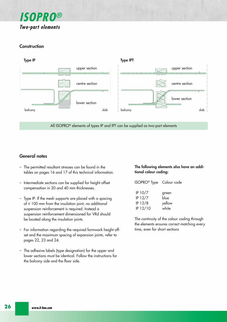
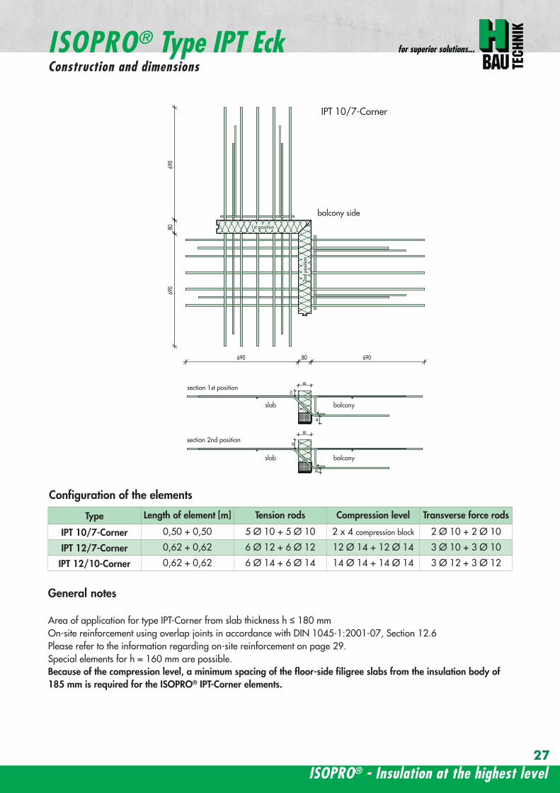
ISOPROreg - Insulation at the highest level
for superior solutions
27
balcony sidebalcony side
section 1st position
section 2nd position
slab balcony
1st position
2nd
posi
tion
cv
cvslab balcony
slab balcony
section 1st position
section 2nd position
1st position
2nd
posi
tion
slab balcony
IPT 127 Corner 820mmIPT 1210 Corner 960mm
IPT 127 Corner 820mmIPT 1210 Corner 960mm
IPT
127
Cor
ner
820m
mIP
T 12
10
Cor
ner
960m
mIP
T 12
7 C
orne
r82
0mm
IPT
121
0 C
orne
r96
0mm
General notes
Area of application for type IPT-Corner from slab thickness h le 180 mmOn-site reinforcement using overlap joints in accordance with DIN 1045-12001-07 Section 126Please refer to the information regarding on-site reinforcement on page 29Special elements for h = 160 mm are possibleBecause of the compression level a minimum spacing of the floor-side filigree slabs from the insulation body of185 mm is required for the ISOPROreg IPT-Corner elements
Type Length of element [m] Tension rods Compression level Transverse force rods
IPT 107-Corner 050 + 050 5 Oslash 10 + 5 Oslash 10 2 x 4 compression block 2 Oslash 10 + 2 Oslash 10
IPT 127-Corner 062 + 062 6 Oslash 12 + 6 Oslash 12 12 Oslash 14 + 12 Oslash 14 3 Oslash 10 + 3 Oslash 10
IPT 1210-Corner 062 + 062 6 Oslash 14 + 6 Oslash 14 14 Oslash 14 + 14 Oslash 14 3 Oslash 12 + 3 Oslash 12
Configuration of the elements
IPT 107-Corner
ISOPROreg Type IPT EckConstruction and dimensions
wwwh-baucom28
Plate thickness [mm] referred to cv [mm] Dimensional values for acceptable load moments MRd [kNm]
30 35 IPT 107 Corner IPT 127 Corner IPT 1210 Corner- 180 169 277 320
180 - 178 292 337- 190 186 306 354
190 - 195 320 370- 200 203 335 387
200 - 212 349 404- 210 220 363 421
210 - 229 378 437- 220 237 392 454
220 - 246 406 471- 230 254 421 487
230 - 263 435 504- 240 271 449 521
240 - 280 463 537- 250 289 478 554
250 - 297 492 571Dimensional values for acceptable transverse forces VRd [kN]
h = 180 - 250 [mm] 483 724 1043
balcony sidebalcony side
section 1st position
section 2nd position
slab balcony
1st position
2nd
posi
tion
cv
cvslab balcony
slab balcony
section 1st position
section 2nd position
1st position
2nd
posi
tion
slab balcony
IPT 127 Corner 820mmIPT 1210 Corner 960mm
IPT 127 Corner 820mmIPT 1210 Corner 960mm
IPT
127
Cor
ner
820m
mIP
T 12
10
Cor
ner
960m
mIP
T 12
7 C
orne
r82
0mm
IPT
121
0 C
orne
r96
0mm
Dimensioning table for concrete gege C2025
IPT 127-CornerIPT 1210-Corner
ISOPROreg Type IPT CornerConstruction and dimensions
ISOPROreg - Insulation at the highest level
for superior solutions
29
1st position
2nd
posi
tion
balcony slab
a
da
b b
c c
dstarter bar 1st position supplementary reinforcement
supplementary reinforcement
supp
lem
enta
ry r
einf
orce
men
t
supp
lem
enta
ry r
einf
orce
men
t
starter bar 1st position
stra
ter
bar
2nd
posi
tion
star
ter
bar
2nd
posi
tion
Type IPT 107-Corner IPT 127-Corner IPT 1210-Corner
starter bar 1st position 5 Oslash 10 6 Oslash 12 6 Oslash 14
starter bar 2nd position 5 Oslash 10 6 Oslash 12 6 Oslash 14
Supplementaryreinforcement 5 Oslash 10 6 Oslash 12 6 Oslash 14
Supplementaryreinforcement 5 Oslash 10 6 Oslash 12 6 Oslash 14
extension of the tension reinforcement internally as well as externally length = 2 x balcony cantilever length
ISOPROreg Type IPT CornerOn-site reinforcement
wwwh-baucom30
ISOPROreg - Insulation at the highest level
for superior solutions
IPQ IPQIPH
IPH
IPH
IPH
IPQS IPQSIPH IPQQS IPQQSIPH
IPQ IPQ
IPQ
IPQQ IPQQ
IPQQ IPQQIP
QS
IPQ IPQ
IPQ
Z
IPQ
S tie rod inlower position
IPQQ IPQQ
IPQ
Z
IPQ
S tie rod inlower position
propped balcony
internal-corner balcony with props
ISOPROreg
Examples of transverse force elements
propped balcony
propped balcony with selective point connection
internal-corner balcony with props
inset balcony with tieback3-sided overlying loggia with tieback
propped balcony with selective point connection
31
wwwh-baucom32
1000
1000
balcony slab balcony slab
IPQ 86 495 mmIPQ 88 495 mmIPQ 106 615 mmIPQ 126 740 mm
IPQ 86 495 mmIPQ 88 495 mmIPQ 106 615 mmIPQ 126 740 mm80
370 80 150
Calculated values for acceptable transverse forces vRd [kNm]
Element height IPQ 64 IPQ 65 IPQ 66 IPQ 68 IPQ 610
160 - 250 mm 348 435 522 695 869
Type IPQ 64 IPQ 65 IPQ 66 IPQ 68 IPQ 610Length [mm] 1000 1000 1000 1000 1000
Transverse force rods 4 Oslash 6 5 Oslash 6 6 Oslash 6 8 Oslash 6 10 Oslash 6
Compression blocks 4 4 4 4 4needed As [cmsup2] 08 10 12 16 20
Dimensioning table - Type IPQ for concrete gege C2025
Configuration of the elements Type IPQ
section
Top view
ISOPROreg Type IPQConstruction and dimensions
IPQ 64 - 610
min Element hight depentend on rod diameter Oslash 10 h ge170 Oslash 12 h ge180 Oslash 14 h ge190
ISOPROreg - Insulation at the highest level
for superior solutions
33
balcony slab
upper reinforcement of steel bars or mesh
lower reinforcement of steel bars or mesh
transverse shear force reinforcement 2 Oslash 8
insert stirrup
ls ls
a
b
c
d
d
a
c
d
b
suspension reinforcemente
ed
secondary reinforcement 2 Oslash 8
concrete concrete
The on-site suspension reinforcement pos and should be calculated for VRd (cf type test No 0519) and loca-ted next to the transverse force rods A Oslash 8 mm steel distribution rod should be installed above and below The sus-pension reinforcement can be replaced by a mesh support (see type IP page 18)DIN 1045-1 Section 1033 applies to the proof of the transverse force capacity of the slabs without shear reinforce-ment For proof of the transverse force capacity of the slabs with shear reinforcement DIN 1045-1 Section 1034 ap-plies The maximum transmissible transverse force across the joints must be limited to 03 VRdmax zu begrenzen
ISOPROreg Type IPQOn-site reinforcement
Calculated values for acceptable transverse forces vRd [kNm]
Element height IPQ 86 IPQ 88 IPQ 106 IPQ 125 IPQ 126
160 - 250 mm 927 1236 1449 1739 2089
Type IPQ 86 IPQ 88 IPQ 106 IPQ 125 IPQ 126Length [mm] 1000 1000 1000 1000 1000
Transverse force rods 6 Oslash 8 8 Oslash 8 6 Oslash 10 5 Oslash 12 6 Oslash 12
Compression blocks 4 4 4 4 4needed As [cmsup2] 21 28 33 40 48
Configuration of the elements Type IPQ
min Element hight depentend on rod diameter Oslash 10 h ge170 Oslash 12 h ge180 Oslash 14 h ge190
wwwh-baucom34
ISOPROreg Type IPQS 2Construction and dimensions
balcony slab
balcony slab
Calculated values for acceptable transverse forces VRd [kN]
Element height IPQS 62 IPQS 82 IPQS 102 IPQS 122 IPQS 142
160 - 250 mm 174 309 483 695 947
Dimensioning table - Type IPQS2 for concrete gege C2025
Type IPQS 62 IPQS 82 IPQS 102 IPQS 122 IPQS 142
Element length [mm] 300 300 300 300 300
Transverse force rods 2 Oslash 6 2 Oslash 8 2 Oslash 10 2 Oslash 12 2 Oslash 14
Compression rods 2 Oslash 10 2 Oslash 10 3 Oslash 10 4 Oslash 12 4 Oslash 14needed As [cmsup2] 040 071 111 160 218
Configuration of the elements Type IPQS2
min Element height dependent on rod diameter Oslash 10 h ge170 Oslash 12 h ge180 Oslash 14 h ge190
IPQS 82 495mmIPQS102 615mmIPQS122 740mmIPQS 142 860mm
IPQS 62
IPQS 82 495mmIPQS102 615mmIPQS122 740mmIPQS 142 860mm
ISOPROreg - Insulation at the highest level
for superior solutions
35
Calculated values for acceptable transverse forces VRd [kN]
Element height IPQS 63 IPQS 83 IPQS 103 IPQS 123 IPQS 143
160 - 250 mm 261 464 724 1043 1420
Dimensioning table - Type IPQS3 for concrete gege C2025
Type IPQS 63 IPQS 83 IPQS 103 IPQS 123 IPQS 143
Element length [mm] 400 400 400 400 400
Transverse force rods 3 Oslash 6 3 Oslash 8 3 Oslash 10 3 Oslash 12 3 Oslash 14
Compression rods 2 Oslash 10 3 Oslash 10 4 Oslash 12 5 Oslash 12 6 Oslash 14needed As [cmsup2] 060 107 167 240 327
Configuration of the elements Type IPQS3
balcony slab
balcony slab
ISOPROreg Type IPQS 3Construction and dimensionsn
IPQS 83 495mmIPQS103 615mmIPQS123 740mmIPQS 143 860mm
IPQS 63
IPQS 83 495mmIPQS103 615mmIPQS123 740mmIPQS 143 860mm
min Element height dependent on rod diameter Oslash 10 h ge170 Oslash 12 h ge180 Oslash 14 h ge190
wwwh-baucom36
ISOPROreg Type IPQQConstruction and dimensions
1000
1000
balcony balconyslab slab
180 80 150 80165 165
370 80 80150
IPQQ 86 495 mmIPQQ 106 615 mmIPQQ 126 740 mm
IPQQ 86 495 mmIPQQ 106 615 mmIPQQ 126 740 mm
IPQQ 64 IPQQ 66IPQQ 68 IPQQ 610
Calculated values for acceptable transverse forces vRd [kNm]
Element height IPQQ 64 IPQQ 66 IPQQ 68 IPQQ 610 IPQQ 86 IPQQ 106 IPQQ 126
160 - 250 mm plusmn348 plusmn522 plusmn695 plusmn869 plusmn927 plusmn1449 plusmn2086
Type IPQQ 64 IPQQ 66 IPQQ 68 IPQQ 610 IPQQ 86 IPQQ 106 IPQQ 126Element length [mm] 500 + 500 500 + 500 500 + 500 500 + 500 500 + 500 500 + 500 500 + 500Transverse force rods 2x4 Oslash 6 2x6 Oslash 6 2x8 Oslash 6 2x10 Oslash 6 2x6 Oslash 8 2x6 Oslash 10 2x6 Oslash 12
Compression rods 4 Oslash 10 4 Oslash 10 6 Oslash 10 6 Oslash 10 6 Oslash 10 10 Oslash 10 10 Oslash 12needed As [cmsup2] 080 120 160 200 213 333 480
Dimensioning table - Type IPQQ for concrete gege C2025
Configuration of the elements Typ IPQQ
Top view
Section
min Element height dependent on rod diameter Oslash 10 h ge170 Oslash 12 h ge180 Oslash 14 h ge190
ISOPROreg - Insulation at the highest level
for superior solutions
37
ISOPROreg Type IPQQOn-site reinforcement
balcony slab
upper reinforcement of steel bars or mesh
lower reinforcement of steel bars or mesh
ls ls
b
c
a
c
d
b
insert stirrupa
d
dinsert stirrupa
ad
d
secondary reinforcement 2 Oslash 8
concrete concrete
secondary reinforcement 2 Oslash 8
The on-site suspension reinforcement pos should be calculated for VRd and located next to the transverse forcerods A Oslash 8 mm steel distribution rod should be installed above and below DIN 1045-1 Section 1033 applies to the proof of the transverse force capacity of the slabs without shear reinforce-ment For proof of the transverse force capacity of the slabs with shear reinforcement DIN 1045-1 Section 1034 ap-plies The maximum transmissible transverse force across the joints must be limited to 03 VRdmax
wwwh-baucom38
ISOPROreg Type IPQQS 2Construction and dimensions
balcony slab
balcony slab
Calculated values for acceptable transverse forces VRd [kN]
Element height IPQQS 62 IPQQS 82 IPQQS 102 IPQQS 122 IPQQS 142
160 - 250 mm plusmn174 plusmn309 plusmn483 plusmn695 plusmn947
Dimensioning table - Type IPQQS2 for concrete gege C2025
Type IPQQS 62 IPQQS 82 IPQQS 102 IPQQS 122 IPQQS 142
Element length [mm] 300 300 300 300 300
Transverse force rods 2x 2 Oslash 6 2x 2 Oslash 8 2x 2 Oslash 10 2x 2 Oslash 12 2x 2 Oslash 14
Compression rods 2 Oslash 10 2 Oslash 10 3 Oslash 10 4 Oslash 12 4 Oslash 14needed As [cmsup2] 040 071 111 160 218
Configuration of the elements Type IPQQS2
IPQQS 82 495mmIPQQS 102 615mmIPQQS 122 740mmIPQQS 142 860mm
IPQQS 62
IPQQS 82 495mmIPQQS 102 615mmIPQQS 122 740mmIPQQS 142 860mm
min Element height dependent on rod diameter Oslash 10 h ge170 Oslash 12 h ge180 Oslash 14 h ge190
ISOPROreg - Insulation at the highest level
for superior solutions
39
ISOPROreg Type IPQQS 3Construction and dimensions
balcony slab
balcony slab
Calculated values for acceptable transverse forces VRd [kN]
Element height IPQQS 63 IPQQS 83 IPQQS 103 IPQQS 123 IPQQS 143
160 - 250 mm plusmn261 plusmn464 plusmn724 plusmn1043 plusmn1420
Dimensioning table - Type IPQQS3 for concrete gege C2025
Type IPQQS 63 IPQQS 83 IPQQS 103 IPQQS 123 IPQQS 143
Element length [mm] 400 400 400 400 400
Transverse force rods 2x 3 Oslash 6 2x 3 Oslash 8 2x 3 Oslash 10 2x 3 Oslash 12 2x 3 Oslash 14
Compression rods 2 Oslash 10 3 Oslash 10 4 Oslash 12 5 Oslash 12 6 Oslash 14needed As [cmsup2] 060 107 167 240 327
Configuration of the elements Type IPQQS3
min Element height dependent on rod diameter Oslash 10 h ge170 Oslash 12 h ge180 Oslash 14 h ge190 alternatively in Element length 500 mm available
IPQQS 83 495mmIPQQS 103 615mmIPQQS 123 740mmIPQQS 143 860mm
IPQQS 63
IPQQS 83 495mmIPQQS 103 615mmIPQQS 123 740mmIPQQS 143 860mm
wwwh-baucom40
ISOPROreg Type IPTDConstruction and dimensions
IPTD IPTD
inset balcony
30
balcony slab
Top view
Section
Example
Table of Dimensions ndash Type IPTD [length in mm]
TypeTension rod Transverse force rod Compression rod Supplemental transverse force
ZL QL DL Q10L Q12LIPTD 126 820 497 820 617 742IPTD 127 820 497 820 617 742IPTD 1210 820 497 820 617 742IPTD 1212 820 497 820 617 742IPTD 1410 960 497 960 617 742
ISOPROreg - Insulation at the highest level
for superior solutions
41
ISOPROreg Type IPTDOn-site reinforcement
balcony slab
upper reinforcement of steelbars or mesh
lower reinforcement of steelbars or mesh
secondary reinforcement 2 Oslash 8
secondary reinforcement 2 Oslash 8
insert stirrup
ls ls
AA
a
b
c
d
d
a
c
d
b
lower reinforcement of steelbars or meshc
upper reinforcement of steelbars or meshb
d
insert stirrupee
b
c
a
a
Section A - A
ISOPRO transverse force rods ISOPRO compression rods
ISOPRO transverse force rods ISOPRO tension rods
d
concrete concrete
The on-site suspension reinforcement pos should be calculated for VRd and located next to the transverse forcerods A Oslash 8 mm steel distribution rod should be installed above and below DIN 1045-1 Section 1033 applies to the proof of the transverse force capacity of the slabs without shear reinforce-ment For proof of the transverse force capacity of the slabs with shear reinforcement DIN 1045-1 Section 1034 ap-plies The maximum transmissible transverse force across the joints must be limited to 03 VRdmax
wwwh-baucom42
ISOPROreg Type IPTDDimensioning table for concrete gege C2025
Plate thickness [mm] withreference to cv [mm] Rated values for moment loading mRd [kNmm]
30 35 IPTD 126IPTD 126
Q10IPTD 126
Q12IPTD 127
IPTD 127Q10
IPTD 127Q12
IPTD 1210
- 160 plusmn 145 - - plusmn 182 - - plusmn 253160 - plusmn 154 - - plusmn 193 - - plusmn 269- 170 plusmn 162 plusmn 146 - plusmn 204 plusmn 187 - plusmn 284
170 - plusmn 171 plusmn 154 - plusmn 214 plusmn 197 - plusmn 299- 180 plusmn 180 plusmn 162 plusmn 145 plusmn 225 plusmn 208 plusmn 190 plusmn 314
180 - plusmn 189 plusmn 170 plusmn 152 plusmn 236 plusmn 218 plusmn 199 plusmn 330- 190 plusmn 197 plusmn 178 plusmn 159 plusmn 247 plusmn 228 plusmn 209 plusmn 345
190 - plusmn 206 plusmn 186 plusmn 166 plusmn 258 plusmn 238 plusmn 218 plusmn 360- 200 plusmn 215 plusmn 194 plusmn 173 plusmn 269 plusmn 248 plusmn 227 plusmn 375
200 - plusmn 223 plusmn 202 plusmn 180 plusmn 280 plusmn 258 plusmn 236 plusmn 391- 210 plusmn 232 plusmn 209 plusmn 187 plusmn 291 plusmn 268 plusmn 246 plusmn 406
210 - plusmn 241 plusmn 217 plusmn 194 plusmn 302 plusmn 278 plusmn 255 plusmn 421- 220 plusmn 250 plusmn 225 plusmn 201 plusmn 313 plusmn 288 plusmn 264 plusmn 437
220 - plusmn 258 plusmn 233 plusmn 208 plusmn 324 plusmn 298 plusmn 273 plusmn 452- 230 plusmn 267 plusmn 241 plusmn 215 plusmn 335 plusmn 308 plusmn 283 plusmn 467
230 - plusmn 276 plusmn 249 plusmn 222 plusmn 346 plusmn 318 plusmn 292 plusmn 482- 240 plusmn 285 plusmn 257 plusmn 229 plusmn 357 plusmn 328 plusmn 301 plusmn 498
240 - plusmn 293 plusmn 265 plusmn 236 plusmn 368 plusmn 339 plusmn 310 plusmn 513- 250 plusmn 302 plusmn 272 plusmn 243 plusmn 379 plusmn 349 plusmn 320 plusmn 528
250 - plusmn 311 plusmn 280 plusmn 250 plusmn 390 plusmn 359 plusmn 329 plusmn 543
Rated values for transverse force loading vRd [kNm]
h = 160 - 250 [mm ] plusmn 415 plusmn 762 plusmn 1098 plusmn 415 plusmn 762 plusmn 1098 plusmn 415
Type IPTD 126 IPTD 126Q10
IPTD 126Q12
IPTD 127 IPTD 127Q10
IPTD 127Q12
IPTD 1210
Element lenght [mm] 500 + 500 500 + 500 500 + 500 500 + 500 500 + 500 500 + 500 500 + 500
Tension rods 6 Oslash 12 6 Oslash 12 6 Oslash 122 Oslash 10 + 6 Oslash 12
2 Oslash 10 + 6 Oslash 12
2 Oslash 10 +6 Oslash 12
10 Oslash 12
Transverse forcerods
2x4 Oslash 8 2x4 Oslash 10 2x4 Oslash 12 2x4 Oslash 8 2x4 Oslash 10 2x4 Oslash 12 2x4 Oslash 8
Compression rods 6 Oslash 12 6 Oslash 12 6 Oslash 122 Oslash 10 + 6 Oslash 12
2 Oslash 10 +6 Oslash 12
2 Oslash 10 +6 Oslash 12
10 Oslash 12
Configuration of the elements Type IPTD
ISOPROreg - Insulation at the highest level
for superior solutions
43
ISOPROreg Type IPTDDimensioning table for concrete gege C2025
Rated values for moment loading mRd [kNmm]
IPTD 1210Q10
IPTD 1210Q12
IPTD 1212IPTD 1212
Q10IPTD 1212
Q12IPTD 1410
IPTD 1410Q10
IPTD 1410Q12
- - plusmn 307 - - plusmn 349 - -- - plusmn 326 - - plusmn 371 - -
plusmn 268 - plusmn 345 plusmn 328 - plusmn 392 plusmn 377 -plusmn 282 - plusmn 363 plusmn 346 - plusmn 414 plusmn 397 -plusmn 297 plusmn 279 plusmn 382 plusmn 364 plusmn 346 plusmn 436 plusmn 418 plusmn 401plusmn 311 plusmn 293 plusmn 400 plusmn 381 plusmn 363 plusmn- 457 plusmn 439 plusmn 421plusmn 325 plusmn 306 plusmn 419 plusmn 399 plusmn 380 plusmn 479 plusmn 459 plusmn 441plusmn 340 plusmn 320 plusmn 437 plusmn 417 plusmn 397 plusmn 500 plusmn 480 plusmn 461plusmn 354 plusmn 333 plusmn 456 plusmn 434 plusmn 414 plusmn 522 plusmn 501 plusmn 480plusmn 369 plusmn 347 plusmn 474 plusmn 452 plusmn 430 plusmn 543 plusmn 522 plusmn 500plusmn 383 plusmn 361 plusmn 493 plusmn 470 plusmn 447 plusmn 565 plusmn 542 plusmn 520plusmn 397 plusmn 374 plusmn 511 plusmn 487 plusmn 464 plusmn 587 plusmn 563 plusmn 540plusmn 412 plusmn 388 plusmn 530 plusmn 505 plusmn 481 plusmn 608 plusmn 584 plusmn 560plusmn 426 plusmn 401 plusmn 548 plusmn 523 plusmn 498 plusmn 630 plusmn 604 plusmn 580plusmn 440 plusmn 415 plusmn 567 plusmn 540 plusmn 515 plusmn 351 plusmn 625 plusmn 600plusmn 455 plusmn 428 plusmn 585 plusmn 558 plusmn 531 plusmn 673 plusmn 646 plusmn 619plusmn 469 plusmn 442 plusmn 604 plusmn 576 plusmn 548 plusmn 694 plusmn 666 plusmn 639plusmn 484 plusmn 455 plusmn 622 plusmn 593 plusmn 565 plusmn 716 plusmn 687 plusmn 659plusmn 498 plusmn 469 plusmn 641 plusmn 611 plusmn 582 plusmn 737 plusmn 708 plusmn 679plusmn 512 plusmn 483 plusmn 659 plusmn 629 plusmn 599 plusmn 759 plusmn 728 plusmn 699
Rated values for transverse force loading vRd [kNm]
plusmn 762 plusmn 1098 plusmn 415 plusmn 762 plusmn 1098 plusmn 415 plusmn 762 plusmn 1098
IPTD 1210Q10
IPTD 1210Q12
IPTD 1212 IPTD 1212Q10
IPTD 1212Q12
IPTD 1410 IPTD 1410Q10
IPTD 1410Q12
500 + 500 500 + 500 500 + 500 500 + 500 500 + 500 500 + 500 500 + 500 500 + 500
10 Oslash 12 10 Oslash 12 12 Oslash 12 12 Oslash 12 12 Oslash 12 10 Oslash 14 10 Oslash 14 10 Oslash 14
2x4 Oslash 10 2x4 Oslash 12 2x4 Oslash 8 2x4 Oslash 10 2x4 Oslash 12 2x4 Oslash 8 2x4 Oslash 10 2x4 Oslash 12
10 Oslash 12 10 Oslash 12 12 Oslash 12 12 Oslash 12 12 Oslash 12 10 Oslash 14 10 Oslash 14 10 Oslash 14
wwwh-baucom44
ISOPROreg Type IPQZConstruction and dimensions
300
40
0
300
40
0
balcony slab
balcony slab
For restraint-free support with an IPQZ element it should be opposed by an IPQS element Both elements should bereinforced by a tieback which corresponds in diameter and rod count to the IPQS and IPQZAn on-site stirrup reinforcement is required to connect IPQS to the floor
Calculated values for acceptable transverse forces VRd [kN]
Element height IPQZ 62 IPQZ 82 IPQZ 102 IPQZ 122 IPQZ 142
160 - 250 mm 174 309 483 695 947
IPQZ 63 IPQZ 83 IPQZ 103 IPQZ 123 IPQZ 143
160 - 250 mm 261 464 724 1043 1420
Dimensioning table ndash Type IPQZ for concrete ge C2025
Type IPQZ 62 IPQZ 82 IPQZ 102 IPQZ 122 IPQZ 142Element lenght [mm] 300 300 300 300 300
Transverse force rods 2 Oslash 6 2 Oslash 8 2 Oslash 10 2 Oslash 12 2 Oslash 14
Configuration of the elements
Type IPQZ 63 IPQZ 83 IPQZ 103 IPQZ 123 IPQZ 143Element length [mm] 400 400 400 400 400
Transverse force rods 3 Oslash 6 3 Oslash 8 3 Oslash 10 3 Oslash 12 3 Oslash 14
min Element height dependent on rod diameter Oslash 10 h ge170 Oslash 12 h ge180 Oslash 14 h ge190
IPQZ 82 83 495mmIPQZ102 103 615mmIPQZ122 123 740mmIPQZ 142 143 860mm
IPQZ 82 83 495mmIPQZ102 103 615mmIPQZ122 123 740mmIPQZ 142 143 860mm
IPQZ 62 63
ISOPROreg - Insulation at the highest level
for superior solutions
45
ISOPROreg Type IPQZOn-site reinforcement
Type Tieback Insert stirrup for use with
IPQZ 62 2 Oslash 6 1 Oslash 6 IPQS 62
IPQZ 82 2 Oslash 8 1 Oslash 8 IPQS 82
IPQZ 102 2 Oslash 10 1 Oslash 10 IPQS 102
IPQZ 122 2 Oslash 12 2 Oslash 8 IPQS 122
IPQZ 142 2 Oslash 14 2 Oslash 10 IPQS 142
tie roda
b
stirrup for anchering tie rodb
a
slab slabbalcony
Typ IPQZ Typ IPQS
Type Tieback Insert stirrup for use with
IPQZ 63 3 Oslash 6 2 Oslash 6 IPQS 63
IPQZ 83 3 Oslash 8 2 Oslash 8 IPQS 83
IPQZ 103 3 Oslash 10 2 Oslash 10 IPQS 103
IPQZ 123 3 Oslash 12 3 Oslash 8 IPQS 123
IPQZ 143 3 Oslash 14 3 Oslash 10 IPQS 143
wwwh-baucom46
ISOPROreg Type IPHConstruction and dimensions
The ISOPROreg elements type IPH which absorb horizontal forces must only be used with ISOPROreg cantilever slabs ortransverse force connections
The number of IPH elements to be used is defined by the structural engineer whereby the expansion joint spacing mustbe maintained
When using ISOPROreg IPH elements the force absorption of the line connection must be reduced by the ratio of thelength of the IPH elements to the total connection length as a percentage
independent of cvReinforcement Length of
element
HRd
Transverse force Horizontal Transverse force Horizontal
IPH 1 2 x 1 Oslash 8 - 100 mm plusmn 74 kN -IPH 2 - 1 Oslash 10 100 mm - plusmn181 kNIPH 3 2 x 1 Oslash 8 1 Oslash 10 100 mm plusmn 74 kN plusmn 181 kN
Dimensioning table ndash Type IPH for concrete gege C2025
balcony slab
balcony slab
balcony slab
balcony slab
balcony slab
balcony slab
100
100
100
250 80 250
250 80 250
250 80 250IPH 1 for absorption of horizontal forces parallel to the insulation joint
IPH 2 for absorption of horizontal forces perpendicular to the insulation joint
IPH 3 for absorption of horizontal forces parallel and perpendicular to the insulation joint
ISOPROreg - Insulation at the highest level
for superior solutions
47
ISOPROreg Type IPHOn-site reinforcement
The installation of the ISOPROreg IPH elements is analogous to the installation of the ISOPROreg cantilever slabs or trans-verse force connectionsThe number and positions of the elements are defined in the structural detail The elements must be fixed in their posi-tions
plate slab balcony slab
ls ls
lower reinforcement of steel bars or mesh
d
lower reinforcement of steel bars or mesh
upper reinforcement of steel bars or mesh
a
aa
dc
d
insert stirrup
a
b
c
secondary reinforcement Oslash 8
b
c c
insert stirrup
wwwh-baucom48
ISOPROreg Type IPAConstruction and calculation values
29
0204
0608
1012
1416
1820
2422
2628
0204
0608
1012
1416
1820
2224
2628
0 +10 +20 +30 +40 +50-10-20-30-40-50
dimensioning axis
MEd
VEd
NEd
380
60
gt160
sup3 16
0
130
Section
Mathematical model ndash Static system Interaction diagram
NRd [kN]
M Rd[kNm]
DimensionsLength of element 350 mmFascia thickness 160 ndash 240 mmHeight of element from 160 mmThickness of insulation element 60 mm
ReinforcementTension rods 3 Oslash 8Compression rods 3 Oslash 8Transverse force rods 2 x 2 Oslash 6
Calculated values for NRd = 0MRd 29 kNmelementVRd plusmn 127 kNelement
ISOPROreg - Insulation at the highest level
for superior solutions
49
ISOPROreg Type IPAOn-site reinforcement and installation instructions
400
100
aa
bc
b c
dd
e
f
gh
h
e
g
h
f
inse
rt s
tirru
ps
conn
ectio
n re
info
rcem
ent
conn
ectio
n re
info
rcem
ent
steel bar Oslash 8
upper slab reinforcement
insert stirrups 3 Oslash 8 150 mmsupplied
insert stirrup as constructive edging
lower slab reinforcement
34
160
56 59 60 60 59 56
34
Section Plan
Installation instructions1 Lay lower reinforcement including edging
2 Install ISOPROreg elements type IPA Spacing in accordance with static requirements
3 Install positions and and tie together
4 Lay upper floor reinforcement and tie together with the ISOPROreg reinforcement element
5 Concrete the floor slab Ensure safe positioning
6 Attach the on-site insulation between the ISOPROreg elements
7 Lay the fascia reinforcement and including edging and tie together with the ISOPROreg elements
supplied insulation
Type IPAType IPA
350e = separation of elements
gt 80
gt 16
0
Spacing of the elements Spacing of expansion joints
Expansion joint spacing e le 78 mAbove corner e2 le 35 m
The parapet must be verified as being a continuous supporte = spacing of the elements in accordance with static requirements
wwwh-baucom50
+5 +15 +25 +35-5-15-25-35
05
10
15
0
MEd
NEdVEd
MRdVRd
dimensioning axis
ISOPROreg Type IPFConstruction and calculation values
42034
0
60
100
Section
Mathematical model ndash Static system Interaction diagram
DimensionsLength of element 350 mmHeight of element from 160 mmThickness of insulation element 60 mm
ReinforcementTension rods 3 Oslash 6Compression rods 3 Oslash 6Transverse force rods 2 Oslash 6
Calculated values for NRd = 0MRd plusmn 15 kNmelementVRd + 127 kNelement
NRd [kN]
M Rd[kN
m]
VRd = 127 kN
ISOPROreg - Insulation at the highest level
for superior solutions
51
ISOPROreg Type IPFOn-site reinforcement and installation instructions
b
a insert stirrup min Oslash 6 150 mm
upper slab reinforcement
ac
b
e
d
c lower slab reinforcement
est
eel b
ar Oslash
8
d2
inse
rt s
tirru
p m
in Oslash
6
150
mm
3333
56 59 60 60 59 56
160
350
Section
Plan
Installation instructions1 Lay lower reinforcement including edging
2 Install ISOPROreg elements type IPA Spacing in accordance with static requirements
3 Install positions and and tie together
4 Lay upper floor reinforcement and tie together with the ISOPROreg reinforcement element
5 Concrete the floor slab Ensure safe positioning
6 Attach the on-site insulation between the ISOPROreg elements
7 Lay the fascia reinforcement and including edging and tie together with the ISOPROreg elements
350
60
Type IPF Type IPF
e = separation of elements
supplied insulation
parapet
Spacing of the elements
Spacing of expansion joints
Expansion joint spacing e le 78 mAbove corner e2 le 35 m
The parapet must be verified as beinga continuous support e = spacing of the elements in accor-dance with static requirements
wwwh-baucom52
ISOPROreg Type IPOConstruction and calculation values
23 lK
+PRd
+HEd
lK
sliding film
reinforcedconcrete console
soft-fibre panel
sup3 18
0
sup3 150 60
725
130 60 535
350
sliding film
reinforcedconcrete console
soft-fibre panelsup3
180
sup3 150 60
725
130 60 535
350
Section
Plan Mathematical modelStatic system
DimensionsLength of element 350 mmHeight of element from 180 mmThickness of insulation element 60 mm
ReinforcementTension rods 3 Oslash 6Compression rods 3 Oslash 8Transverse force rods 2 Oslash 10
for Hed = 0 PRd plusmn 171 kNmelement max HRd + 184 kNelement
0 2 4 6 8 10 12 14 16 20 22 Horizontal force HEd [kN]
25
15
10
5
0
P Rd[kN] concrete gege C2530
concrete gege C2025
PRd = 23
PRd = 10
HEd
= 18
4
HEd
= 23
1
ISOPROreg - Insulation at the highest level
for superior solutions
53
ISOPROreg Type IPOOn-site reinforcement and installation instructions
slab
a
a
bde
b
c
c upper reinforcement of steel bars or mesh
lower reinforcement of steel bars or mesh
insert stirrupde
long
itudi
nal r
einf
orce
men
t
clos
ed s
tirru
p
concrete
concrete
Section Installation instructions
1 Lay lower reinforcement including edging
2 Install ISOPROreg elements type IPO Spacingin accordance with static requirements
3 Lay upper floor reinforcement and tie to-gether with the ISOPROreg reinforcement ele-ment
4 Attach the on-site insulation between the ISO-PROreg elements
5 Lay the console reinforcement and andtie together with the ISOPROreg elements Thefloor edge beam must be designed as a con-tinuous support
6 As far as practical the console and the floorshould be concreted simultaneously Ensuresecure positioning
reinforced concrete joist
ISOPRO Type IPO ISOPRO Type IPO
supplied insulation
e = separation of elements350
Spacing of the elements Spacing of expansion joints
Expansion joint spacing e le 78 mAbove corner e2 le 35 m
The parapet must be verified as being a continuous support e = spacing of the elements in accordance with static requirements
wwwh-baucom54
ISOPROreg Type IPSConstruction and calculation values
80
5050
80 ZL
balcony slab plate slab
wall
console
tension rod
transverse force bars
compression strut
ZL
QL
QL
DL
80
DL
100100
BSt 500 Nr Wst Nr 14571
BSt 500 Nr Wst Nr 14571
BSt 500 S
BSt 500 S
Section
80
5050
80 ZL
balcony slab plate slab
wall
console
tension rod
transverse force bars
compression strut
ZL
QL
QL
DL
80
DL
100100
BSt 500 Nr Wst Nr 14571
BSt 500 Nr Wst Nr 14571
BSt 500 S
BSt 500 S
Dimensions - Type IPS [length in mm]
Type Tension rod Transverse forcerod
Compressionrod
ZL QL DLIPS 1 690 500 430IPS 2 820 620 500IPS 3 960 745 570IPS 4 1550 865 600
Dimensioning table for concrete gege C2025Element hight 400 mm IPS 1 IPS 2 IPS 3 IPS 4
moment MRd [kNm] 221 294 375 624
transverse forces VRd [kN] 213 333 480 653
Type IPS 1 IPS 2 IPS 3 IPS 4
Element width [mm] 220 220 220 220
Tension rods 3 Oslash 10 3 Oslash 12 3 Oslash 14 4 Oslash 14
Transverse force rods 2 Oslash 8 2 Oslash 10 2 Oslash 12 2 Oslash 14
Compression rods 3 Oslash 12 3 Oslash 14 3 Oslash 16 3 Oslash 20
Other designs and dimensions are available on requestThe bonding area I underlies the determination of the anchoring lengths However if required the reinforcement rods can also be designed for bonding area II
Configuration of the elements
ISOPROreg - Insulation at the highest level
for superior solutions
55
ISOPROreg Type IPSOn-site reinforcement and installation instructions
wall plate reinforcement to structural calculations
tension rod
transverse force bars
compression strut
a
b
c
d
d
a
b
a closed stirrup
edging
c suspension reinforcementconcrete concrete
Installation instructions
1 Lay wall plate reinforcement to meet structural requirements2 Insert ISOPROreg element type IPS and tie together with the wall
reinforcement Transverse reinforcement in overlap zone in accordance with DIN 1045-1
3 Install and tie together beam reinforcement and according to structural calculations Pos edging in accordance withDIN 1045-1 Pos installed as a closed stirrup to avoid shearing
4 When concreting make sure that both sides are uniformly filled and compacted
5 Formwork offset for the beam in accordance with structural calculations
wall plate reinforcement to structural calculations
tension rod
transverse force bars
compression strut
a
b
c
d
d
a
b
a closed stirrup
edging
c suspension reinforcementconcrete concrete
80
b b
plate slab
Type IPS
wal
l pla
te
Type IPS wal
l pla
te
balcony slab
supplied insulation
Configuration of the elements Expansion joint spacing
TypeJoint spacing [m]
e
IPS 1 113
IPS 2 101
IPS 3 92
IPS 4 80
For corner constructions the maximumrod leg length is e2
wwwh-baucom56
ISOPROreg Type IPWConstruction and calculation values
ZL ZL80
420 420
QL QL
DL DL
290290
low
er s
ectio
n12
50ce
ntre
sec
tion
uppe
r se
ctio
n25
0
h =
150
- 3
50
m
80
balcony
balcony slab
slab
exte
rnal
wal
l
inte
rnal
wal
l
horizontal transverse force bars
horizontal transverse force bars
upper section bht in mm150-250 250 80
lower section bht in mm150-250 1250 80
Section
Table of Dimensions Type IPW [length in mm]
Type
Tension rod Transverseforce rod
Compressionrod
ZL QL DLIPW 1 600 423 270IPW 2 790 563 335IPW 3 980 653 410IPW 4 1170 783 470
Element width b = 150 ndash 250 mmElement height h = 150 ndash 350 mInsulation material thickness t = 80 mm
Dimensioning table for concrete gege C2025Calculated values for acceptable moments MRdy [kNm]
Element height [m] IPW 1 IPW 2 IPW 3 IPW 415 ndash 20 537 918 1169 154420 ndash 25 737 1267 1614 2132
gt 25 937 1616 2059 2720Calculated values for acceptable transverse forces [kN]
vRdz [kN] 412 622 1066 1535vRdy [kN] plusmn137 plusmn137 plusmn137 plusmn137
Type IPW 1 IPW 2 IPW 3 IPW 4Element height [m] ge150 ge150 ge150 ge150Tension rods 4 Oslash 6 4 Oslash 8 4 Oslash 10 4 Oslash 12Transverse force rods Qz 6 Oslash 6 6 Oslash 8 6 Oslash 10 6 Oslash 12Transverse force rods Qy 2 x 2 Oslash 6 2 x 2 Oslash 6 2 x 2 Oslash 6 2 x 2 Oslash 6Compression rods 6 Oslash 8 6 Oslash 10 6 Oslash 12 6 Oslash 14
Configuration of the elements
Moment effects from wind loading are absorbed bythe stiffening effect of the balcony slab
MRdz = 0
Bonding area II underlies the determination of theoverlap lengths On request the anchoring lengthscan also be dimensioned for bonding area I Designsand dimensions deviating from the standard ele-ments are available on request
ISOPROreg - Insulation at the highest level
for superior solutions
57
ISOPROreg Type IPWOn-site reinforcement and installation instructions
MRdz
VRdz VRdy
x
z
y
MRdy
Mathematical model ndash Static system
balcony slab
balcony slab
steel
mes
h re
info
rcem
ent
a
steel
mes
h re
info
rcem
ent
b
e connection reinforcementto structural calculations
f
insert stirrupas constructive edging c
c
d steel bar min 2 Oslash 8
concrete sup3 2025
exte
rnal
wal
l
inte
rnal
wal
l
insert stirrupas constructive edging
connection reinforcementto structural calculations
a bc c
d
d
steel bar min 2 Oslash 8
steel bar min 2 Oslash 8
insert stirrupinsert stirrupsteel mesh reinforcement steel mesh reinforcement
80
wall p
late
wall p
late
balcony slab
plate slab
Type IPWsupplied insulation
Type IPW
b b
e e e
Configuration of the elements
Installation instructions
1 Position internal wall reinforcement 2 Attach the constructive edging inter-
nally (insert stirrup)3 Starting at the bottom assemble the in-
dividual ISOPROreg elements type IPWand tie together with the wall reinforce-ment
4 Erect and internally and tie to-gether
5 Position the external wall reinforce-ments and in accordancewith structural design and tie to theISOPROreg elements
6 When concreting pay particular atten-tion to the positional security of the ele-ments It is recommended to fill andcompact both wall plates at the sametime
wwwh-baucom58
ISOPROreg
Approvals and Type testing
Approvals
ISOPRO Type IP Z-157-244ISOPRO Type IPT Z-157-243
Type testing
ISOPRO Type IP Test No 0517ISOPRO Type IPT Test No 0518ISOPRO Type IPQ Test No 0519
ISOPROreg - Insulation at the highest level
for superior solutions
59
ISOPROreg
Tender
___________________________________________________________________________
Scope Application area DIN 276013 Concrete and reinforced concrete Floor constructions
Structural installations__________________________________________________________________________________
ISOPROreg supporting and thermally insulating connection elements
01 supporting the balcony slab using ISOPROreg elements from H-BAU Technik GmbH02 required for installation03 m Type IP cv = mm h = mm04 m Type IPQ cv = mm h = mm05 part Type cv = mm h = mm
Special fabrication according to the following description
06 for thermal separation of the concrete07 for the storey floors pos 08 for the roofing pos 09 for 10 and11 for the balcony slap pos 12 for the loggia slab pos 13 for the cantilever slab pos 14 for the 15 in fire protection construction class F9016 the bonding is made in the reinforcement of pos and pos 17 deliver18 deliver install and bond with the connection reinforcement19 only install and bond with the connection reinforcement delivery provided20 the installation is made in accordance with instructions from
H-BAU Technik GmbHAm Guumlterbahnhof 2079771 Klettgau-ErzingenGermanyTel +49 (0) 77 42 92 15-20Fax +49 (0) 77 42 92 15-90
21 in accordance with the detail and reinforcement drawings no 22 material 23 wages 24 unit price
25 total price
wwwh-baucom60
NOTES
ISOPROreg - Insulation at the highest level
for superior solutions
61
NOTES
wwwh-baucom
Concreting with system
ISOPROreg
KESIIRAPIDOBATreg
JSDHEDFERBOXreg
BOXFERreg
GRIPRIPreg
PENTAFLEXreg
RIPINOXreg
WARMBORDreg
SCHALBORDreg
ZEMBORDreg
SCHALL-ISO ACCESSORIES
H-BAU Technik GmbHAm Guumlterbahnhof 20D-79771 Klettgau-ErzingenTel + 49 (0) 7742 92 15-20Fax + 49 (0) 7742 92 15-90infoklettgauh-baude
Produktion Nord-OstBrandenburger StraszligeD-14641 WachowTel + 49 (0) 3 3239 775-20Fax + 49 (0) 3 3239 775-90infoberlinh-baude
Balcony insulation elementsLifting anchorsShuttering tubesPush-in pegsReinforcement connectorsReinforcement connectorsMasonry connectorsSealing technologyRustproof stainless steelStop end panelsStop end panelsStop end panelsSound insulation elementsSpacers
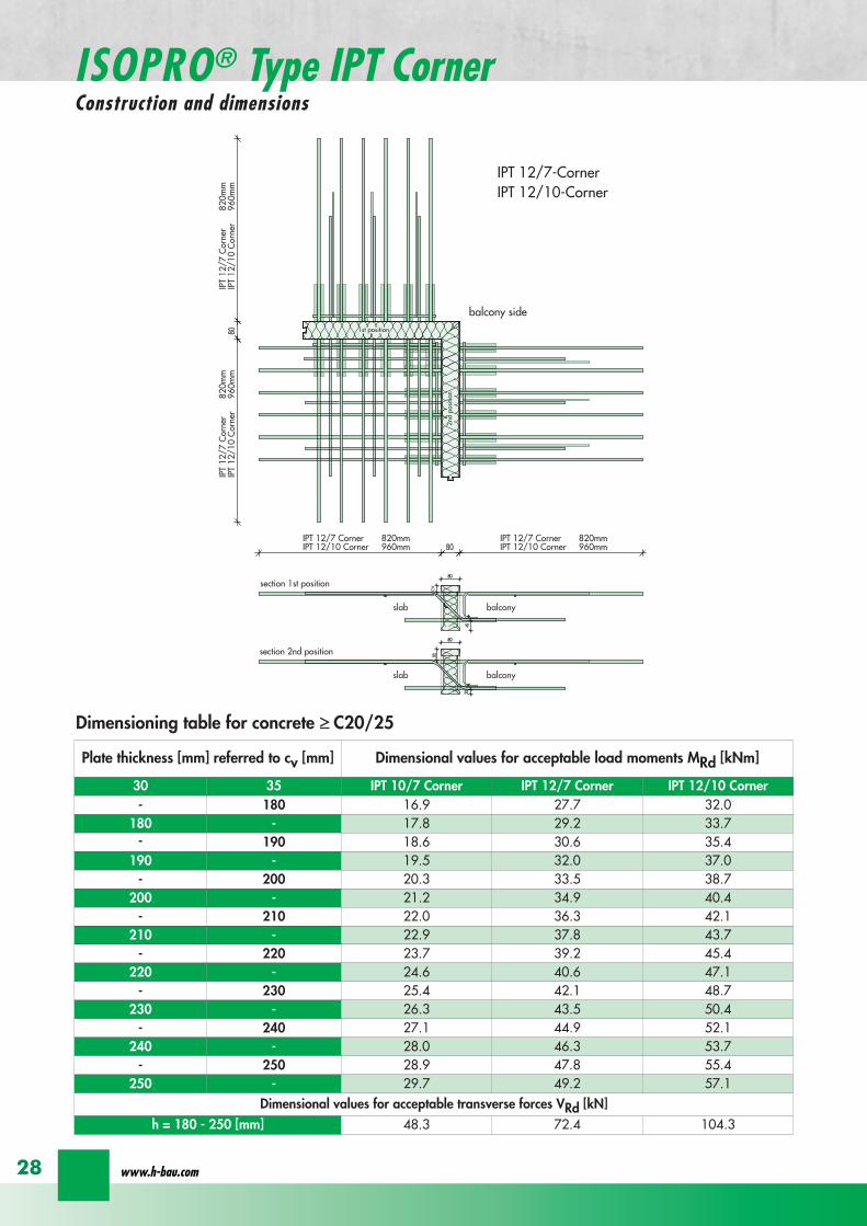
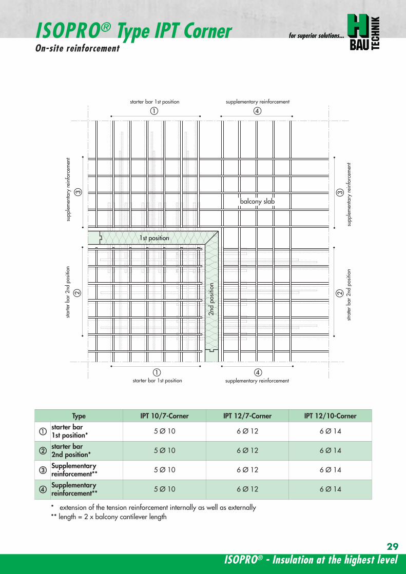
ISOPROreg - Insulation at the highest level
for superior solutions
29
1st position
2nd
posi
tion
balcony slab
a
da
b b
c c
dstarter bar 1st position supplementary reinforcement
supplementary reinforcement
supp
lem
enta
ry r
einf
orce
men
t
supp
lem
enta
ry r
einf
orce
men
t
starter bar 1st position
stra
ter
bar
2nd
posi
tion
star
ter
bar
2nd
posi
tion
Type IPT 107-Corner IPT 127-Corner IPT 1210-Corner
starter bar 1st position 5 Oslash 10 6 Oslash 12 6 Oslash 14
starter bar 2nd position 5 Oslash 10 6 Oslash 12 6 Oslash 14
Supplementaryreinforcement 5 Oslash 10 6 Oslash 12 6 Oslash 14
Supplementaryreinforcement 5 Oslash 10 6 Oslash 12 6 Oslash 14
extension of the tension reinforcement internally as well as externally length = 2 x balcony cantilever length
ISOPROreg Type IPT CornerOn-site reinforcement
wwwh-baucom30
ISOPROreg - Insulation at the highest level
for superior solutions
IPQ IPQIPH
IPH
IPH
IPH
IPQS IPQSIPH IPQQS IPQQSIPH
IPQ IPQ
IPQ
IPQQ IPQQ
IPQQ IPQQIP
QS
IPQ IPQ
IPQ
Z
IPQ
S tie rod inlower position
IPQQ IPQQ
IPQ
Z
IPQ
S tie rod inlower position
propped balcony
internal-corner balcony with props
ISOPROreg
Examples of transverse force elements
propped balcony
propped balcony with selective point connection
internal-corner balcony with props
inset balcony with tieback3-sided overlying loggia with tieback
propped balcony with selective point connection
31
wwwh-baucom32
1000
1000
balcony slab balcony slab
IPQ 86 495 mmIPQ 88 495 mmIPQ 106 615 mmIPQ 126 740 mm
IPQ 86 495 mmIPQ 88 495 mmIPQ 106 615 mmIPQ 126 740 mm80
370 80 150
Calculated values for acceptable transverse forces vRd [kNm]
Element height IPQ 64 IPQ 65 IPQ 66 IPQ 68 IPQ 610
160 - 250 mm 348 435 522 695 869
Type IPQ 64 IPQ 65 IPQ 66 IPQ 68 IPQ 610Length [mm] 1000 1000 1000 1000 1000
Transverse force rods 4 Oslash 6 5 Oslash 6 6 Oslash 6 8 Oslash 6 10 Oslash 6
Compression blocks 4 4 4 4 4needed As [cmsup2] 08 10 12 16 20
Dimensioning table - Type IPQ for concrete gege C2025
Configuration of the elements Type IPQ
section
Top view
ISOPROreg Type IPQConstruction and dimensions
IPQ 64 - 610
min Element hight depentend on rod diameter Oslash 10 h ge170 Oslash 12 h ge180 Oslash 14 h ge190
ISOPROreg - Insulation at the highest level
for superior solutions
33
balcony slab
upper reinforcement of steel bars or mesh
lower reinforcement of steel bars or mesh
transverse shear force reinforcement 2 Oslash 8
insert stirrup
ls ls
a
b
c
d
d
a
c
d
b
suspension reinforcemente
ed
secondary reinforcement 2 Oslash 8
concrete concrete
The on-site suspension reinforcement pos and should be calculated for VRd (cf type test No 0519) and loca-ted next to the transverse force rods A Oslash 8 mm steel distribution rod should be installed above and below The sus-pension reinforcement can be replaced by a mesh support (see type IP page 18)DIN 1045-1 Section 1033 applies to the proof of the transverse force capacity of the slabs without shear reinforce-ment For proof of the transverse force capacity of the slabs with shear reinforcement DIN 1045-1 Section 1034 ap-plies The maximum transmissible transverse force across the joints must be limited to 03 VRdmax zu begrenzen
ISOPROreg Type IPQOn-site reinforcement
Calculated values for acceptable transverse forces vRd [kNm]
Element height IPQ 86 IPQ 88 IPQ 106 IPQ 125 IPQ 126
160 - 250 mm 927 1236 1449 1739 2089
Type IPQ 86 IPQ 88 IPQ 106 IPQ 125 IPQ 126Length [mm] 1000 1000 1000 1000 1000
Transverse force rods 6 Oslash 8 8 Oslash 8 6 Oslash 10 5 Oslash 12 6 Oslash 12
Compression blocks 4 4 4 4 4needed As [cmsup2] 21 28 33 40 48
Configuration of the elements Type IPQ
min Element hight depentend on rod diameter Oslash 10 h ge170 Oslash 12 h ge180 Oslash 14 h ge190
wwwh-baucom34
ISOPROreg Type IPQS 2Construction and dimensions
balcony slab
balcony slab
Calculated values for acceptable transverse forces VRd [kN]
Element height IPQS 62 IPQS 82 IPQS 102 IPQS 122 IPQS 142
160 - 250 mm 174 309 483 695 947
Dimensioning table - Type IPQS2 for concrete gege C2025
Type IPQS 62 IPQS 82 IPQS 102 IPQS 122 IPQS 142
Element length [mm] 300 300 300 300 300
Transverse force rods 2 Oslash 6 2 Oslash 8 2 Oslash 10 2 Oslash 12 2 Oslash 14
Compression rods 2 Oslash 10 2 Oslash 10 3 Oslash 10 4 Oslash 12 4 Oslash 14needed As [cmsup2] 040 071 111 160 218
Configuration of the elements Type IPQS2
min Element height dependent on rod diameter Oslash 10 h ge170 Oslash 12 h ge180 Oslash 14 h ge190
IPQS 82 495mmIPQS102 615mmIPQS122 740mmIPQS 142 860mm
IPQS 62
IPQS 82 495mmIPQS102 615mmIPQS122 740mmIPQS 142 860mm
ISOPROreg - Insulation at the highest level
for superior solutions
35
Calculated values for acceptable transverse forces VRd [kN]
Element height IPQS 63 IPQS 83 IPQS 103 IPQS 123 IPQS 143
160 - 250 mm 261 464 724 1043 1420
Dimensioning table - Type IPQS3 for concrete gege C2025
Type IPQS 63 IPQS 83 IPQS 103 IPQS 123 IPQS 143
Element length [mm] 400 400 400 400 400
Transverse force rods 3 Oslash 6 3 Oslash 8 3 Oslash 10 3 Oslash 12 3 Oslash 14
Compression rods 2 Oslash 10 3 Oslash 10 4 Oslash 12 5 Oslash 12 6 Oslash 14needed As [cmsup2] 060 107 167 240 327
Configuration of the elements Type IPQS3
balcony slab
balcony slab
ISOPROreg Type IPQS 3Construction and dimensionsn
IPQS 83 495mmIPQS103 615mmIPQS123 740mmIPQS 143 860mm
IPQS 63
IPQS 83 495mmIPQS103 615mmIPQS123 740mmIPQS 143 860mm
min Element height dependent on rod diameter Oslash 10 h ge170 Oslash 12 h ge180 Oslash 14 h ge190
wwwh-baucom36
ISOPROreg Type IPQQConstruction and dimensions
1000
1000
balcony balconyslab slab
180 80 150 80165 165
370 80 80150
IPQQ 86 495 mmIPQQ 106 615 mmIPQQ 126 740 mm
IPQQ 86 495 mmIPQQ 106 615 mmIPQQ 126 740 mm
IPQQ 64 IPQQ 66IPQQ 68 IPQQ 610
Calculated values for acceptable transverse forces vRd [kNm]
Element height IPQQ 64 IPQQ 66 IPQQ 68 IPQQ 610 IPQQ 86 IPQQ 106 IPQQ 126
160 - 250 mm plusmn348 plusmn522 plusmn695 plusmn869 plusmn927 plusmn1449 plusmn2086
Type IPQQ 64 IPQQ 66 IPQQ 68 IPQQ 610 IPQQ 86 IPQQ 106 IPQQ 126Element length [mm] 500 + 500 500 + 500 500 + 500 500 + 500 500 + 500 500 + 500 500 + 500Transverse force rods 2x4 Oslash 6 2x6 Oslash 6 2x8 Oslash 6 2x10 Oslash 6 2x6 Oslash 8 2x6 Oslash 10 2x6 Oslash 12
Compression rods 4 Oslash 10 4 Oslash 10 6 Oslash 10 6 Oslash 10 6 Oslash 10 10 Oslash 10 10 Oslash 12needed As [cmsup2] 080 120 160 200 213 333 480
Dimensioning table - Type IPQQ for concrete gege C2025
Configuration of the elements Typ IPQQ
Top view
Section
min Element height dependent on rod diameter Oslash 10 h ge170 Oslash 12 h ge180 Oslash 14 h ge190
ISOPROreg - Insulation at the highest level
for superior solutions
37
ISOPROreg Type IPQQOn-site reinforcement
balcony slab
upper reinforcement of steel bars or mesh
lower reinforcement of steel bars or mesh
ls ls
b
c
a
c
d
b
insert stirrupa
d
dinsert stirrupa
ad
d
secondary reinforcement 2 Oslash 8
concrete concrete
secondary reinforcement 2 Oslash 8
The on-site suspension reinforcement pos should be calculated for VRd and located next to the transverse forcerods A Oslash 8 mm steel distribution rod should be installed above and below DIN 1045-1 Section 1033 applies to the proof of the transverse force capacity of the slabs without shear reinforce-ment For proof of the transverse force capacity of the slabs with shear reinforcement DIN 1045-1 Section 1034 ap-plies The maximum transmissible transverse force across the joints must be limited to 03 VRdmax
wwwh-baucom38
ISOPROreg Type IPQQS 2Construction and dimensions
balcony slab
balcony slab
Calculated values for acceptable transverse forces VRd [kN]
Element height IPQQS 62 IPQQS 82 IPQQS 102 IPQQS 122 IPQQS 142
160 - 250 mm plusmn174 plusmn309 plusmn483 plusmn695 plusmn947
Dimensioning table - Type IPQQS2 for concrete gege C2025
Type IPQQS 62 IPQQS 82 IPQQS 102 IPQQS 122 IPQQS 142
Element length [mm] 300 300 300 300 300
Transverse force rods 2x 2 Oslash 6 2x 2 Oslash 8 2x 2 Oslash 10 2x 2 Oslash 12 2x 2 Oslash 14
Compression rods 2 Oslash 10 2 Oslash 10 3 Oslash 10 4 Oslash 12 4 Oslash 14needed As [cmsup2] 040 071 111 160 218
Configuration of the elements Type IPQQS2
IPQQS 82 495mmIPQQS 102 615mmIPQQS 122 740mmIPQQS 142 860mm
IPQQS 62
IPQQS 82 495mmIPQQS 102 615mmIPQQS 122 740mmIPQQS 142 860mm
min Element height dependent on rod diameter Oslash 10 h ge170 Oslash 12 h ge180 Oslash 14 h ge190
ISOPROreg - Insulation at the highest level
for superior solutions
39
ISOPROreg Type IPQQS 3Construction and dimensions
balcony slab
balcony slab
Calculated values for acceptable transverse forces VRd [kN]
Element height IPQQS 63 IPQQS 83 IPQQS 103 IPQQS 123 IPQQS 143
160 - 250 mm plusmn261 plusmn464 plusmn724 plusmn1043 plusmn1420
Dimensioning table - Type IPQQS3 for concrete gege C2025
Type IPQQS 63 IPQQS 83 IPQQS 103 IPQQS 123 IPQQS 143
Element length [mm] 400 400 400 400 400
Transverse force rods 2x 3 Oslash 6 2x 3 Oslash 8 2x 3 Oslash 10 2x 3 Oslash 12 2x 3 Oslash 14
Compression rods 2 Oslash 10 3 Oslash 10 4 Oslash 12 5 Oslash 12 6 Oslash 14needed As [cmsup2] 060 107 167 240 327
Configuration of the elements Type IPQQS3
min Element height dependent on rod diameter Oslash 10 h ge170 Oslash 12 h ge180 Oslash 14 h ge190 alternatively in Element length 500 mm available
IPQQS 83 495mmIPQQS 103 615mmIPQQS 123 740mmIPQQS 143 860mm
IPQQS 63
IPQQS 83 495mmIPQQS 103 615mmIPQQS 123 740mmIPQQS 143 860mm
wwwh-baucom40
ISOPROreg Type IPTDConstruction and dimensions
IPTD IPTD
inset balcony
30
balcony slab
Top view
Section
Example
Table of Dimensions ndash Type IPTD [length in mm]
TypeTension rod Transverse force rod Compression rod Supplemental transverse force
ZL QL DL Q10L Q12LIPTD 126 820 497 820 617 742IPTD 127 820 497 820 617 742IPTD 1210 820 497 820 617 742IPTD 1212 820 497 820 617 742IPTD 1410 960 497 960 617 742
ISOPROreg - Insulation at the highest level
for superior solutions
41
ISOPROreg Type IPTDOn-site reinforcement
balcony slab
upper reinforcement of steelbars or mesh
lower reinforcement of steelbars or mesh
secondary reinforcement 2 Oslash 8
secondary reinforcement 2 Oslash 8
insert stirrup
ls ls
AA
a
b
c
d
d
a
c
d
b
lower reinforcement of steelbars or meshc
upper reinforcement of steelbars or meshb
d
insert stirrupee
b
c
a
a
Section A - A
ISOPRO transverse force rods ISOPRO compression rods
ISOPRO transverse force rods ISOPRO tension rods
d
concrete concrete
The on-site suspension reinforcement pos should be calculated for VRd and located next to the transverse forcerods A Oslash 8 mm steel distribution rod should be installed above and below DIN 1045-1 Section 1033 applies to the proof of the transverse force capacity of the slabs without shear reinforce-ment For proof of the transverse force capacity of the slabs with shear reinforcement DIN 1045-1 Section 1034 ap-plies The maximum transmissible transverse force across the joints must be limited to 03 VRdmax
wwwh-baucom42
ISOPROreg Type IPTDDimensioning table for concrete gege C2025
Plate thickness [mm] withreference to cv [mm] Rated values for moment loading mRd [kNmm]
30 35 IPTD 126IPTD 126
Q10IPTD 126
Q12IPTD 127
IPTD 127Q10
IPTD 127Q12
IPTD 1210
- 160 plusmn 145 - - plusmn 182 - - plusmn 253160 - plusmn 154 - - plusmn 193 - - plusmn 269- 170 plusmn 162 plusmn 146 - plusmn 204 plusmn 187 - plusmn 284
170 - plusmn 171 plusmn 154 - plusmn 214 plusmn 197 - plusmn 299- 180 plusmn 180 plusmn 162 plusmn 145 plusmn 225 plusmn 208 plusmn 190 plusmn 314
180 - plusmn 189 plusmn 170 plusmn 152 plusmn 236 plusmn 218 plusmn 199 plusmn 330- 190 plusmn 197 plusmn 178 plusmn 159 plusmn 247 plusmn 228 plusmn 209 plusmn 345
190 - plusmn 206 plusmn 186 plusmn 166 plusmn 258 plusmn 238 plusmn 218 plusmn 360- 200 plusmn 215 plusmn 194 plusmn 173 plusmn 269 plusmn 248 plusmn 227 plusmn 375
200 - plusmn 223 plusmn 202 plusmn 180 plusmn 280 plusmn 258 plusmn 236 plusmn 391- 210 plusmn 232 plusmn 209 plusmn 187 plusmn 291 plusmn 268 plusmn 246 plusmn 406
210 - plusmn 241 plusmn 217 plusmn 194 plusmn 302 plusmn 278 plusmn 255 plusmn 421- 220 plusmn 250 plusmn 225 plusmn 201 plusmn 313 plusmn 288 plusmn 264 plusmn 437
220 - plusmn 258 plusmn 233 plusmn 208 plusmn 324 plusmn 298 plusmn 273 plusmn 452- 230 plusmn 267 plusmn 241 plusmn 215 plusmn 335 plusmn 308 plusmn 283 plusmn 467
230 - plusmn 276 plusmn 249 plusmn 222 plusmn 346 plusmn 318 plusmn 292 plusmn 482- 240 plusmn 285 plusmn 257 plusmn 229 plusmn 357 plusmn 328 plusmn 301 plusmn 498
240 - plusmn 293 plusmn 265 plusmn 236 plusmn 368 plusmn 339 plusmn 310 plusmn 513- 250 plusmn 302 plusmn 272 plusmn 243 plusmn 379 plusmn 349 plusmn 320 plusmn 528
250 - plusmn 311 plusmn 280 plusmn 250 plusmn 390 plusmn 359 plusmn 329 plusmn 543
Rated values for transverse force loading vRd [kNm]
h = 160 - 250 [mm ] plusmn 415 plusmn 762 plusmn 1098 plusmn 415 plusmn 762 plusmn 1098 plusmn 415
Type IPTD 126 IPTD 126Q10
IPTD 126Q12
IPTD 127 IPTD 127Q10
IPTD 127Q12
IPTD 1210
Element lenght [mm] 500 + 500 500 + 500 500 + 500 500 + 500 500 + 500 500 + 500 500 + 500
Tension rods 6 Oslash 12 6 Oslash 12 6 Oslash 122 Oslash 10 + 6 Oslash 12
2 Oslash 10 + 6 Oslash 12
2 Oslash 10 +6 Oslash 12
10 Oslash 12
Transverse forcerods
2x4 Oslash 8 2x4 Oslash 10 2x4 Oslash 12 2x4 Oslash 8 2x4 Oslash 10 2x4 Oslash 12 2x4 Oslash 8
Compression rods 6 Oslash 12 6 Oslash 12 6 Oslash 122 Oslash 10 + 6 Oslash 12
2 Oslash 10 +6 Oslash 12
2 Oslash 10 +6 Oslash 12
10 Oslash 12
Configuration of the elements Type IPTD
ISOPROreg - Insulation at the highest level
for superior solutions
43
ISOPROreg Type IPTDDimensioning table for concrete gege C2025
Rated values for moment loading mRd [kNmm]
IPTD 1210Q10
IPTD 1210Q12
IPTD 1212IPTD 1212
Q10IPTD 1212
Q12IPTD 1410
IPTD 1410Q10
IPTD 1410Q12
- - plusmn 307 - - plusmn 349 - -- - plusmn 326 - - plusmn 371 - -
plusmn 268 - plusmn 345 plusmn 328 - plusmn 392 plusmn 377 -plusmn 282 - plusmn 363 plusmn 346 - plusmn 414 plusmn 397 -plusmn 297 plusmn 279 plusmn 382 plusmn 364 plusmn 346 plusmn 436 plusmn 418 plusmn 401plusmn 311 plusmn 293 plusmn 400 plusmn 381 plusmn 363 plusmn- 457 plusmn 439 plusmn 421plusmn 325 plusmn 306 plusmn 419 plusmn 399 plusmn 380 plusmn 479 plusmn 459 plusmn 441plusmn 340 plusmn 320 plusmn 437 plusmn 417 plusmn 397 plusmn 500 plusmn 480 plusmn 461plusmn 354 plusmn 333 plusmn 456 plusmn 434 plusmn 414 plusmn 522 plusmn 501 plusmn 480plusmn 369 plusmn 347 plusmn 474 plusmn 452 plusmn 430 plusmn 543 plusmn 522 plusmn 500plusmn 383 plusmn 361 plusmn 493 plusmn 470 plusmn 447 plusmn 565 plusmn 542 plusmn 520plusmn 397 plusmn 374 plusmn 511 plusmn 487 plusmn 464 plusmn 587 plusmn 563 plusmn 540plusmn 412 plusmn 388 plusmn 530 plusmn 505 plusmn 481 plusmn 608 plusmn 584 plusmn 560plusmn 426 plusmn 401 plusmn 548 plusmn 523 plusmn 498 plusmn 630 plusmn 604 plusmn 580plusmn 440 plusmn 415 plusmn 567 plusmn 540 plusmn 515 plusmn 351 plusmn 625 plusmn 600plusmn 455 plusmn 428 plusmn 585 plusmn 558 plusmn 531 plusmn 673 plusmn 646 plusmn 619plusmn 469 plusmn 442 plusmn 604 plusmn 576 plusmn 548 plusmn 694 plusmn 666 plusmn 639plusmn 484 plusmn 455 plusmn 622 plusmn 593 plusmn 565 plusmn 716 plusmn 687 plusmn 659plusmn 498 plusmn 469 plusmn 641 plusmn 611 plusmn 582 plusmn 737 plusmn 708 plusmn 679plusmn 512 plusmn 483 plusmn 659 plusmn 629 plusmn 599 plusmn 759 plusmn 728 plusmn 699
Rated values for transverse force loading vRd [kNm]
plusmn 762 plusmn 1098 plusmn 415 plusmn 762 plusmn 1098 plusmn 415 plusmn 762 plusmn 1098
IPTD 1210Q10
IPTD 1210Q12
IPTD 1212 IPTD 1212Q10
IPTD 1212Q12
IPTD 1410 IPTD 1410Q10
IPTD 1410Q12
500 + 500 500 + 500 500 + 500 500 + 500 500 + 500 500 + 500 500 + 500 500 + 500
10 Oslash 12 10 Oslash 12 12 Oslash 12 12 Oslash 12 12 Oslash 12 10 Oslash 14 10 Oslash 14 10 Oslash 14
2x4 Oslash 10 2x4 Oslash 12 2x4 Oslash 8 2x4 Oslash 10 2x4 Oslash 12 2x4 Oslash 8 2x4 Oslash 10 2x4 Oslash 12
10 Oslash 12 10 Oslash 12 12 Oslash 12 12 Oslash 12 12 Oslash 12 10 Oslash 14 10 Oslash 14 10 Oslash 14
wwwh-baucom44
ISOPROreg Type IPQZConstruction and dimensions
300
40
0
300
40
0
balcony slab
balcony slab
For restraint-free support with an IPQZ element it should be opposed by an IPQS element Both elements should bereinforced by a tieback which corresponds in diameter and rod count to the IPQS and IPQZAn on-site stirrup reinforcement is required to connect IPQS to the floor
Calculated values for acceptable transverse forces VRd [kN]
Element height IPQZ 62 IPQZ 82 IPQZ 102 IPQZ 122 IPQZ 142
160 - 250 mm 174 309 483 695 947
IPQZ 63 IPQZ 83 IPQZ 103 IPQZ 123 IPQZ 143
160 - 250 mm 261 464 724 1043 1420
Dimensioning table ndash Type IPQZ for concrete ge C2025
Type IPQZ 62 IPQZ 82 IPQZ 102 IPQZ 122 IPQZ 142Element lenght [mm] 300 300 300 300 300
Transverse force rods 2 Oslash 6 2 Oslash 8 2 Oslash 10 2 Oslash 12 2 Oslash 14
Configuration of the elements
Type IPQZ 63 IPQZ 83 IPQZ 103 IPQZ 123 IPQZ 143Element length [mm] 400 400 400 400 400
Transverse force rods 3 Oslash 6 3 Oslash 8 3 Oslash 10 3 Oslash 12 3 Oslash 14
min Element height dependent on rod diameter Oslash 10 h ge170 Oslash 12 h ge180 Oslash 14 h ge190
IPQZ 82 83 495mmIPQZ102 103 615mmIPQZ122 123 740mmIPQZ 142 143 860mm
IPQZ 82 83 495mmIPQZ102 103 615mmIPQZ122 123 740mmIPQZ 142 143 860mm
IPQZ 62 63
ISOPROreg - Insulation at the highest level
for superior solutions
45
ISOPROreg Type IPQZOn-site reinforcement
Type Tieback Insert stirrup for use with
IPQZ 62 2 Oslash 6 1 Oslash 6 IPQS 62
IPQZ 82 2 Oslash 8 1 Oslash 8 IPQS 82
IPQZ 102 2 Oslash 10 1 Oslash 10 IPQS 102
IPQZ 122 2 Oslash 12 2 Oslash 8 IPQS 122
IPQZ 142 2 Oslash 14 2 Oslash 10 IPQS 142
tie roda
b
stirrup for anchering tie rodb
a
slab slabbalcony
Typ IPQZ Typ IPQS
Type Tieback Insert stirrup for use with
IPQZ 63 3 Oslash 6 2 Oslash 6 IPQS 63
IPQZ 83 3 Oslash 8 2 Oslash 8 IPQS 83
IPQZ 103 3 Oslash 10 2 Oslash 10 IPQS 103
IPQZ 123 3 Oslash 12 3 Oslash 8 IPQS 123
IPQZ 143 3 Oslash 14 3 Oslash 10 IPQS 143
wwwh-baucom46
ISOPROreg Type IPHConstruction and dimensions
The ISOPROreg elements type IPH which absorb horizontal forces must only be used with ISOPROreg cantilever slabs ortransverse force connections
The number of IPH elements to be used is defined by the structural engineer whereby the expansion joint spacing mustbe maintained
When using ISOPROreg IPH elements the force absorption of the line connection must be reduced by the ratio of thelength of the IPH elements to the total connection length as a percentage
independent of cvReinforcement Length of
element
HRd
Transverse force Horizontal Transverse force Horizontal
IPH 1 2 x 1 Oslash 8 - 100 mm plusmn 74 kN -IPH 2 - 1 Oslash 10 100 mm - plusmn181 kNIPH 3 2 x 1 Oslash 8 1 Oslash 10 100 mm plusmn 74 kN plusmn 181 kN
Dimensioning table ndash Type IPH for concrete gege C2025
balcony slab
balcony slab
balcony slab
balcony slab
balcony slab
balcony slab
100
100
100
250 80 250
250 80 250
250 80 250IPH 1 for absorption of horizontal forces parallel to the insulation joint
IPH 2 for absorption of horizontal forces perpendicular to the insulation joint
IPH 3 for absorption of horizontal forces parallel and perpendicular to the insulation joint
ISOPROreg - Insulation at the highest level
for superior solutions
47
ISOPROreg Type IPHOn-site reinforcement
The installation of the ISOPROreg IPH elements is analogous to the installation of the ISOPROreg cantilever slabs or trans-verse force connectionsThe number and positions of the elements are defined in the structural detail The elements must be fixed in their posi-tions
plate slab balcony slab
ls ls
lower reinforcement of steel bars or mesh
d
lower reinforcement of steel bars or mesh
upper reinforcement of steel bars or mesh
a
aa
dc
d
insert stirrup
a
b
c
secondary reinforcement Oslash 8
b
c c
insert stirrup
wwwh-baucom48
ISOPROreg Type IPAConstruction and calculation values
29
0204
0608
1012
1416
1820
2422
2628
0204
0608
1012
1416
1820
2224
2628
0 +10 +20 +30 +40 +50-10-20-30-40-50
dimensioning axis
MEd
VEd
NEd
380
60
gt160
sup3 16
0
130
Section
Mathematical model ndash Static system Interaction diagram
NRd [kN]
M Rd[kNm]
DimensionsLength of element 350 mmFascia thickness 160 ndash 240 mmHeight of element from 160 mmThickness of insulation element 60 mm
ReinforcementTension rods 3 Oslash 8Compression rods 3 Oslash 8Transverse force rods 2 x 2 Oslash 6
Calculated values for NRd = 0MRd 29 kNmelementVRd plusmn 127 kNelement
ISOPROreg - Insulation at the highest level
for superior solutions
49
ISOPROreg Type IPAOn-site reinforcement and installation instructions
400
100
aa
bc
b c
dd
e
f
gh
h
e
g
h
f
inse
rt s
tirru
ps
conn
ectio
n re
info
rcem
ent
conn
ectio
n re
info
rcem
ent
steel bar Oslash 8
upper slab reinforcement
insert stirrups 3 Oslash 8 150 mmsupplied
insert stirrup as constructive edging
lower slab reinforcement
34
160
56 59 60 60 59 56
34
Section Plan
Installation instructions1 Lay lower reinforcement including edging
2 Install ISOPROreg elements type IPA Spacing in accordance with static requirements
3 Install positions and and tie together
4 Lay upper floor reinforcement and tie together with the ISOPROreg reinforcement element
5 Concrete the floor slab Ensure safe positioning
6 Attach the on-site insulation between the ISOPROreg elements
7 Lay the fascia reinforcement and including edging and tie together with the ISOPROreg elements
supplied insulation
Type IPAType IPA
350e = separation of elements
gt 80
gt 16
0
Spacing of the elements Spacing of expansion joints
Expansion joint spacing e le 78 mAbove corner e2 le 35 m
The parapet must be verified as being a continuous supporte = spacing of the elements in accordance with static requirements
wwwh-baucom50
+5 +15 +25 +35-5-15-25-35
05
10
15
0
MEd
NEdVEd
MRdVRd
dimensioning axis
ISOPROreg Type IPFConstruction and calculation values
42034
0
60
100
Section
Mathematical model ndash Static system Interaction diagram
DimensionsLength of element 350 mmHeight of element from 160 mmThickness of insulation element 60 mm
ReinforcementTension rods 3 Oslash 6Compression rods 3 Oslash 6Transverse force rods 2 Oslash 6
Calculated values for NRd = 0MRd plusmn 15 kNmelementVRd + 127 kNelement
NRd [kN]
M Rd[kN
m]
VRd = 127 kN
ISOPROreg - Insulation at the highest level
for superior solutions
51
ISOPROreg Type IPFOn-site reinforcement and installation instructions
b
a insert stirrup min Oslash 6 150 mm
upper slab reinforcement
ac
b
e
d
c lower slab reinforcement
est
eel b
ar Oslash
8
d2
inse
rt s
tirru
p m
in Oslash
6
150
mm
3333
56 59 60 60 59 56
160
350
Section
Plan
Installation instructions1 Lay lower reinforcement including edging
2 Install ISOPROreg elements type IPA Spacing in accordance with static requirements
3 Install positions and and tie together
4 Lay upper floor reinforcement and tie together with the ISOPROreg reinforcement element
5 Concrete the floor slab Ensure safe positioning
6 Attach the on-site insulation between the ISOPROreg elements
7 Lay the fascia reinforcement and including edging and tie together with the ISOPROreg elements
350
60
Type IPF Type IPF
e = separation of elements
supplied insulation
parapet
Spacing of the elements
Spacing of expansion joints
Expansion joint spacing e le 78 mAbove corner e2 le 35 m
The parapet must be verified as beinga continuous support e = spacing of the elements in accor-dance with static requirements
wwwh-baucom52
ISOPROreg Type IPOConstruction and calculation values
23 lK
+PRd
+HEd
lK
sliding film
reinforcedconcrete console
soft-fibre panel
sup3 18
0
sup3 150 60
725
130 60 535
350
sliding film
reinforcedconcrete console
soft-fibre panelsup3
180
sup3 150 60
725
130 60 535
350
Section
Plan Mathematical modelStatic system
DimensionsLength of element 350 mmHeight of element from 180 mmThickness of insulation element 60 mm
ReinforcementTension rods 3 Oslash 6Compression rods 3 Oslash 8Transverse force rods 2 Oslash 10
for Hed = 0 PRd plusmn 171 kNmelement max HRd + 184 kNelement
0 2 4 6 8 10 12 14 16 20 22 Horizontal force HEd [kN]
25
15
10
5
0
P Rd[kN] concrete gege C2530
concrete gege C2025
PRd = 23
PRd = 10
HEd
= 18
4
HEd
= 23
1
ISOPROreg - Insulation at the highest level
for superior solutions
53
ISOPROreg Type IPOOn-site reinforcement and installation instructions
slab
a
a
bde
b
c
c upper reinforcement of steel bars or mesh
lower reinforcement of steel bars or mesh
insert stirrupde
long
itudi
nal r
einf
orce
men
t
clos
ed s
tirru
p
concrete
concrete
Section Installation instructions
1 Lay lower reinforcement including edging
2 Install ISOPROreg elements type IPO Spacingin accordance with static requirements
3 Lay upper floor reinforcement and tie to-gether with the ISOPROreg reinforcement ele-ment
4 Attach the on-site insulation between the ISO-PROreg elements
5 Lay the console reinforcement and andtie together with the ISOPROreg elements Thefloor edge beam must be designed as a con-tinuous support
6 As far as practical the console and the floorshould be concreted simultaneously Ensuresecure positioning
reinforced concrete joist
ISOPRO Type IPO ISOPRO Type IPO
supplied insulation
e = separation of elements350
Spacing of the elements Spacing of expansion joints
Expansion joint spacing e le 78 mAbove corner e2 le 35 m
The parapet must be verified as being a continuous support e = spacing of the elements in accordance with static requirements
wwwh-baucom54
ISOPROreg Type IPSConstruction and calculation values
80
5050
80 ZL
balcony slab plate slab
wall
console
tension rod
transverse force bars
compression strut
ZL
QL
QL
DL
80
DL
100100
BSt 500 Nr Wst Nr 14571
BSt 500 Nr Wst Nr 14571
BSt 500 S
BSt 500 S
Section
80
5050
80 ZL
balcony slab plate slab
wall
console
tension rod
transverse force bars
compression strut
ZL
QL
QL
DL
80
DL
100100
BSt 500 Nr Wst Nr 14571
BSt 500 Nr Wst Nr 14571
BSt 500 S
BSt 500 S
Dimensions - Type IPS [length in mm]
Type Tension rod Transverse forcerod
Compressionrod
ZL QL DLIPS 1 690 500 430IPS 2 820 620 500IPS 3 960 745 570IPS 4 1550 865 600
Dimensioning table for concrete gege C2025Element hight 400 mm IPS 1 IPS 2 IPS 3 IPS 4
moment MRd [kNm] 221 294 375 624
transverse forces VRd [kN] 213 333 480 653
Type IPS 1 IPS 2 IPS 3 IPS 4
Element width [mm] 220 220 220 220
Tension rods 3 Oslash 10 3 Oslash 12 3 Oslash 14 4 Oslash 14
Transverse force rods 2 Oslash 8 2 Oslash 10 2 Oslash 12 2 Oslash 14
Compression rods 3 Oslash 12 3 Oslash 14 3 Oslash 16 3 Oslash 20
Other designs and dimensions are available on requestThe bonding area I underlies the determination of the anchoring lengths However if required the reinforcement rods can also be designed for bonding area II
Configuration of the elements
ISOPROreg - Insulation at the highest level
for superior solutions
55
ISOPROreg Type IPSOn-site reinforcement and installation instructions
wall plate reinforcement to structural calculations
tension rod
transverse force bars
compression strut
a
b
c
d
d
a
b
a closed stirrup
edging
c suspension reinforcementconcrete concrete
Installation instructions
1 Lay wall plate reinforcement to meet structural requirements2 Insert ISOPROreg element type IPS and tie together with the wall
reinforcement Transverse reinforcement in overlap zone in accordance with DIN 1045-1
3 Install and tie together beam reinforcement and according to structural calculations Pos edging in accordance withDIN 1045-1 Pos installed as a closed stirrup to avoid shearing
4 When concreting make sure that both sides are uniformly filled and compacted
5 Formwork offset for the beam in accordance with structural calculations
wall plate reinforcement to structural calculations
tension rod
transverse force bars
compression strut
a
b
c
d
d
a
b
a closed stirrup
edging
c suspension reinforcementconcrete concrete
80
b b
plate slab
Type IPS
wal
l pla
te
Type IPS wal
l pla
te
balcony slab
supplied insulation
Configuration of the elements Expansion joint spacing
TypeJoint spacing [m]
e
IPS 1 113
IPS 2 101
IPS 3 92
IPS 4 80
For corner constructions the maximumrod leg length is e2
wwwh-baucom56
ISOPROreg Type IPWConstruction and calculation values
ZL ZL80
420 420
QL QL
DL DL
290290
low
er s
ectio
n12
50ce
ntre
sec
tion
uppe
r se
ctio
n25
0
h =
150
- 3
50
m
80
balcony
balcony slab
slab
exte
rnal
wal
l
inte
rnal
wal
l
horizontal transverse force bars
horizontal transverse force bars
upper section bht in mm150-250 250 80
lower section bht in mm150-250 1250 80
Section
Table of Dimensions Type IPW [length in mm]
Type
Tension rod Transverseforce rod
Compressionrod
ZL QL DLIPW 1 600 423 270IPW 2 790 563 335IPW 3 980 653 410IPW 4 1170 783 470
Element width b = 150 ndash 250 mmElement height h = 150 ndash 350 mInsulation material thickness t = 80 mm
Dimensioning table for concrete gege C2025Calculated values for acceptable moments MRdy [kNm]
Element height [m] IPW 1 IPW 2 IPW 3 IPW 415 ndash 20 537 918 1169 154420 ndash 25 737 1267 1614 2132
gt 25 937 1616 2059 2720Calculated values for acceptable transverse forces [kN]
vRdz [kN] 412 622 1066 1535vRdy [kN] plusmn137 plusmn137 plusmn137 plusmn137
Type IPW 1 IPW 2 IPW 3 IPW 4Element height [m] ge150 ge150 ge150 ge150Tension rods 4 Oslash 6 4 Oslash 8 4 Oslash 10 4 Oslash 12Transverse force rods Qz 6 Oslash 6 6 Oslash 8 6 Oslash 10 6 Oslash 12Transverse force rods Qy 2 x 2 Oslash 6 2 x 2 Oslash 6 2 x 2 Oslash 6 2 x 2 Oslash 6Compression rods 6 Oslash 8 6 Oslash 10 6 Oslash 12 6 Oslash 14
Configuration of the elements
Moment effects from wind loading are absorbed bythe stiffening effect of the balcony slab
MRdz = 0
Bonding area II underlies the determination of theoverlap lengths On request the anchoring lengthscan also be dimensioned for bonding area I Designsand dimensions deviating from the standard ele-ments are available on request
ISOPROreg - Insulation at the highest level
for superior solutions
57
ISOPROreg Type IPWOn-site reinforcement and installation instructions
MRdz
VRdz VRdy
x
z
y
MRdy
Mathematical model ndash Static system
balcony slab
balcony slab
steel
mes
h re
info
rcem
ent
a
steel
mes
h re
info
rcem
ent
b
e connection reinforcementto structural calculations
f
insert stirrupas constructive edging c
c
d steel bar min 2 Oslash 8
concrete sup3 2025
exte
rnal
wal
l
inte
rnal
wal
l
insert stirrupas constructive edging
connection reinforcementto structural calculations
a bc c
d
d
steel bar min 2 Oslash 8
steel bar min 2 Oslash 8
insert stirrupinsert stirrupsteel mesh reinforcement steel mesh reinforcement
80
wall p
late
wall p
late
balcony slab
plate slab
Type IPWsupplied insulation
Type IPW
b b
e e e
Configuration of the elements
Installation instructions
1 Position internal wall reinforcement 2 Attach the constructive edging inter-
nally (insert stirrup)3 Starting at the bottom assemble the in-
dividual ISOPROreg elements type IPWand tie together with the wall reinforce-ment
4 Erect and internally and tie to-gether
5 Position the external wall reinforce-ments and in accordancewith structural design and tie to theISOPROreg elements
6 When concreting pay particular atten-tion to the positional security of the ele-ments It is recommended to fill andcompact both wall plates at the sametime
wwwh-baucom58
ISOPROreg
Approvals and Type testing
Approvals
ISOPRO Type IP Z-157-244ISOPRO Type IPT Z-157-243
Type testing
ISOPRO Type IP Test No 0517ISOPRO Type IPT Test No 0518ISOPRO Type IPQ Test No 0519
ISOPROreg - Insulation at the highest level
for superior solutions
59
ISOPROreg
Tender
___________________________________________________________________________
Scope Application area DIN 276013 Concrete and reinforced concrete Floor constructions
Structural installations__________________________________________________________________________________
ISOPROreg supporting and thermally insulating connection elements
01 supporting the balcony slab using ISOPROreg elements from H-BAU Technik GmbH02 required for installation03 m Type IP cv = mm h = mm04 m Type IPQ cv = mm h = mm05 part Type cv = mm h = mm
Special fabrication according to the following description
06 for thermal separation of the concrete07 for the storey floors pos 08 for the roofing pos 09 for 10 and11 for the balcony slap pos 12 for the loggia slab pos 13 for the cantilever slab pos 14 for the 15 in fire protection construction class F9016 the bonding is made in the reinforcement of pos and pos 17 deliver18 deliver install and bond with the connection reinforcement19 only install and bond with the connection reinforcement delivery provided20 the installation is made in accordance with instructions from
H-BAU Technik GmbHAm Guumlterbahnhof 2079771 Klettgau-ErzingenGermanyTel +49 (0) 77 42 92 15-20Fax +49 (0) 77 42 92 15-90
21 in accordance with the detail and reinforcement drawings no 22 material 23 wages 24 unit price
25 total price
wwwh-baucom60
NOTES
ISOPROreg - Insulation at the highest level
for superior solutions
61
NOTES
wwwh-baucom
Concreting with system
ISOPROreg
KESIIRAPIDOBATreg
JSDHEDFERBOXreg
BOXFERreg
GRIPRIPreg
PENTAFLEXreg
RIPINOXreg
WARMBORDreg
SCHALBORDreg
ZEMBORDreg
SCHALL-ISO ACCESSORIES
H-BAU Technik GmbHAm Guumlterbahnhof 20D-79771 Klettgau-ErzingenTel + 49 (0) 7742 92 15-20Fax + 49 (0) 7742 92 15-90infoklettgauh-baude
Produktion Nord-OstBrandenburger StraszligeD-14641 WachowTel + 49 (0) 3 3239 775-20Fax + 49 (0) 3 3239 775-90infoberlinh-baude
Balcony insulation elementsLifting anchorsShuttering tubesPush-in pegsReinforcement connectorsReinforcement connectorsMasonry connectorsSealing technologyRustproof stainless steelStop end panelsStop end panelsStop end panelsSound insulation elementsSpacers
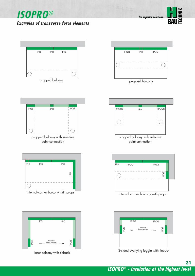
ISOPROreg - Insulation at the highest level
for superior solutions
IPQ IPQIPH
IPH
IPH
IPH
IPQS IPQSIPH IPQQS IPQQSIPH
IPQ IPQ
IPQ
IPQQ IPQQ
IPQQ IPQQIP
QS
IPQ IPQ
IPQ
Z
IPQ
S tie rod inlower position
IPQQ IPQQ
IPQ
Z
IPQ
S tie rod inlower position
propped balcony
internal-corner balcony with props
ISOPROreg
Examples of transverse force elements
propped balcony
propped balcony with selective point connection
internal-corner balcony with props
inset balcony with tieback3-sided overlying loggia with tieback
propped balcony with selective point connection
31
wwwh-baucom32
1000
1000
balcony slab balcony slab
IPQ 86 495 mmIPQ 88 495 mmIPQ 106 615 mmIPQ 126 740 mm
IPQ 86 495 mmIPQ 88 495 mmIPQ 106 615 mmIPQ 126 740 mm80
370 80 150
Calculated values for acceptable transverse forces vRd [kNm]
Element height IPQ 64 IPQ 65 IPQ 66 IPQ 68 IPQ 610
160 - 250 mm 348 435 522 695 869
Type IPQ 64 IPQ 65 IPQ 66 IPQ 68 IPQ 610Length [mm] 1000 1000 1000 1000 1000
Transverse force rods 4 Oslash 6 5 Oslash 6 6 Oslash 6 8 Oslash 6 10 Oslash 6
Compression blocks 4 4 4 4 4needed As [cmsup2] 08 10 12 16 20
Dimensioning table - Type IPQ for concrete gege C2025
Configuration of the elements Type IPQ
section
Top view
ISOPROreg Type IPQConstruction and dimensions
IPQ 64 - 610
min Element hight depentend on rod diameter Oslash 10 h ge170 Oslash 12 h ge180 Oslash 14 h ge190
ISOPROreg - Insulation at the highest level
for superior solutions
33
balcony slab
upper reinforcement of steel bars or mesh
lower reinforcement of steel bars or mesh
transverse shear force reinforcement 2 Oslash 8
insert stirrup
ls ls
a
b
c
d
d
a
c
d
b
suspension reinforcemente
ed
secondary reinforcement 2 Oslash 8
concrete concrete
The on-site suspension reinforcement pos and should be calculated for VRd (cf type test No 0519) and loca-ted next to the transverse force rods A Oslash 8 mm steel distribution rod should be installed above and below The sus-pension reinforcement can be replaced by a mesh support (see type IP page 18)DIN 1045-1 Section 1033 applies to the proof of the transverse force capacity of the slabs without shear reinforce-ment For proof of the transverse force capacity of the slabs with shear reinforcement DIN 1045-1 Section 1034 ap-plies The maximum transmissible transverse force across the joints must be limited to 03 VRdmax zu begrenzen
ISOPROreg Type IPQOn-site reinforcement
Calculated values for acceptable transverse forces vRd [kNm]
Element height IPQ 86 IPQ 88 IPQ 106 IPQ 125 IPQ 126
160 - 250 mm 927 1236 1449 1739 2089
Type IPQ 86 IPQ 88 IPQ 106 IPQ 125 IPQ 126Length [mm] 1000 1000 1000 1000 1000
Transverse force rods 6 Oslash 8 8 Oslash 8 6 Oslash 10 5 Oslash 12 6 Oslash 12
Compression blocks 4 4 4 4 4needed As [cmsup2] 21 28 33 40 48
Configuration of the elements Type IPQ
min Element hight depentend on rod diameter Oslash 10 h ge170 Oslash 12 h ge180 Oslash 14 h ge190
wwwh-baucom34
ISOPROreg Type IPQS 2Construction and dimensions
balcony slab
balcony slab
Calculated values for acceptable transverse forces VRd [kN]
Element height IPQS 62 IPQS 82 IPQS 102 IPQS 122 IPQS 142
160 - 250 mm 174 309 483 695 947
Dimensioning table - Type IPQS2 for concrete gege C2025
Type IPQS 62 IPQS 82 IPQS 102 IPQS 122 IPQS 142
Element length [mm] 300 300 300 300 300
Transverse force rods 2 Oslash 6 2 Oslash 8 2 Oslash 10 2 Oslash 12 2 Oslash 14
Compression rods 2 Oslash 10 2 Oslash 10 3 Oslash 10 4 Oslash 12 4 Oslash 14needed As [cmsup2] 040 071 111 160 218
Configuration of the elements Type IPQS2
min Element height dependent on rod diameter Oslash 10 h ge170 Oslash 12 h ge180 Oslash 14 h ge190
IPQS 82 495mmIPQS102 615mmIPQS122 740mmIPQS 142 860mm
IPQS 62
IPQS 82 495mmIPQS102 615mmIPQS122 740mmIPQS 142 860mm
ISOPROreg - Insulation at the highest level
for superior solutions
35
Calculated values for acceptable transverse forces VRd [kN]
Element height IPQS 63 IPQS 83 IPQS 103 IPQS 123 IPQS 143
160 - 250 mm 261 464 724 1043 1420
Dimensioning table - Type IPQS3 for concrete gege C2025
Type IPQS 63 IPQS 83 IPQS 103 IPQS 123 IPQS 143
Element length [mm] 400 400 400 400 400
Transverse force rods 3 Oslash 6 3 Oslash 8 3 Oslash 10 3 Oslash 12 3 Oslash 14
Compression rods 2 Oslash 10 3 Oslash 10 4 Oslash 12 5 Oslash 12 6 Oslash 14needed As [cmsup2] 060 107 167 240 327
Configuration of the elements Type IPQS3
balcony slab
balcony slab
ISOPROreg Type IPQS 3Construction and dimensionsn
IPQS 83 495mmIPQS103 615mmIPQS123 740mmIPQS 143 860mm
IPQS 63
IPQS 83 495mmIPQS103 615mmIPQS123 740mmIPQS 143 860mm
min Element height dependent on rod diameter Oslash 10 h ge170 Oslash 12 h ge180 Oslash 14 h ge190
wwwh-baucom36
ISOPROreg Type IPQQConstruction and dimensions
1000
1000
balcony balconyslab slab
180 80 150 80165 165
370 80 80150
IPQQ 86 495 mmIPQQ 106 615 mmIPQQ 126 740 mm
IPQQ 86 495 mmIPQQ 106 615 mmIPQQ 126 740 mm
IPQQ 64 IPQQ 66IPQQ 68 IPQQ 610
Calculated values for acceptable transverse forces vRd [kNm]
Element height IPQQ 64 IPQQ 66 IPQQ 68 IPQQ 610 IPQQ 86 IPQQ 106 IPQQ 126
160 - 250 mm plusmn348 plusmn522 plusmn695 plusmn869 plusmn927 plusmn1449 plusmn2086
Type IPQQ 64 IPQQ 66 IPQQ 68 IPQQ 610 IPQQ 86 IPQQ 106 IPQQ 126Element length [mm] 500 + 500 500 + 500 500 + 500 500 + 500 500 + 500 500 + 500 500 + 500Transverse force rods 2x4 Oslash 6 2x6 Oslash 6 2x8 Oslash 6 2x10 Oslash 6 2x6 Oslash 8 2x6 Oslash 10 2x6 Oslash 12
Compression rods 4 Oslash 10 4 Oslash 10 6 Oslash 10 6 Oslash 10 6 Oslash 10 10 Oslash 10 10 Oslash 12needed As [cmsup2] 080 120 160 200 213 333 480
Dimensioning table - Type IPQQ for concrete gege C2025
Configuration of the elements Typ IPQQ
Top view
Section
min Element height dependent on rod diameter Oslash 10 h ge170 Oslash 12 h ge180 Oslash 14 h ge190
ISOPROreg - Insulation at the highest level
for superior solutions
37
ISOPROreg Type IPQQOn-site reinforcement
balcony slab
upper reinforcement of steel bars or mesh
lower reinforcement of steel bars or mesh
ls ls
b
c
a
c
d
b
insert stirrupa
d
dinsert stirrupa
ad
d
secondary reinforcement 2 Oslash 8
concrete concrete
secondary reinforcement 2 Oslash 8
The on-site suspension reinforcement pos should be calculated for VRd and located next to the transverse forcerods A Oslash 8 mm steel distribution rod should be installed above and below DIN 1045-1 Section 1033 applies to the proof of the transverse force capacity of the slabs without shear reinforce-ment For proof of the transverse force capacity of the slabs with shear reinforcement DIN 1045-1 Section 1034 ap-plies The maximum transmissible transverse force across the joints must be limited to 03 VRdmax
wwwh-baucom38
ISOPROreg Type IPQQS 2Construction and dimensions
balcony slab
balcony slab
Calculated values for acceptable transverse forces VRd [kN]
Element height IPQQS 62 IPQQS 82 IPQQS 102 IPQQS 122 IPQQS 142
160 - 250 mm plusmn174 plusmn309 plusmn483 plusmn695 plusmn947
Dimensioning table - Type IPQQS2 for concrete gege C2025
Type IPQQS 62 IPQQS 82 IPQQS 102 IPQQS 122 IPQQS 142
Element length [mm] 300 300 300 300 300
Transverse force rods 2x 2 Oslash 6 2x 2 Oslash 8 2x 2 Oslash 10 2x 2 Oslash 12 2x 2 Oslash 14
Compression rods 2 Oslash 10 2 Oslash 10 3 Oslash 10 4 Oslash 12 4 Oslash 14needed As [cmsup2] 040 071 111 160 218
Configuration of the elements Type IPQQS2
IPQQS 82 495mmIPQQS 102 615mmIPQQS 122 740mmIPQQS 142 860mm
IPQQS 62
IPQQS 82 495mmIPQQS 102 615mmIPQQS 122 740mmIPQQS 142 860mm
min Element height dependent on rod diameter Oslash 10 h ge170 Oslash 12 h ge180 Oslash 14 h ge190
ISOPROreg - Insulation at the highest level
for superior solutions
39
ISOPROreg Type IPQQS 3Construction and dimensions
balcony slab
balcony slab
Calculated values for acceptable transverse forces VRd [kN]
Element height IPQQS 63 IPQQS 83 IPQQS 103 IPQQS 123 IPQQS 143
160 - 250 mm plusmn261 plusmn464 plusmn724 plusmn1043 plusmn1420
Dimensioning table - Type IPQQS3 for concrete gege C2025
Type IPQQS 63 IPQQS 83 IPQQS 103 IPQQS 123 IPQQS 143
Element length [mm] 400 400 400 400 400
Transverse force rods 2x 3 Oslash 6 2x 3 Oslash 8 2x 3 Oslash 10 2x 3 Oslash 12 2x 3 Oslash 14
Compression rods 2 Oslash 10 3 Oslash 10 4 Oslash 12 5 Oslash 12 6 Oslash 14needed As [cmsup2] 060 107 167 240 327
Configuration of the elements Type IPQQS3
min Element height dependent on rod diameter Oslash 10 h ge170 Oslash 12 h ge180 Oslash 14 h ge190 alternatively in Element length 500 mm available
IPQQS 83 495mmIPQQS 103 615mmIPQQS 123 740mmIPQQS 143 860mm
IPQQS 63
IPQQS 83 495mmIPQQS 103 615mmIPQQS 123 740mmIPQQS 143 860mm
wwwh-baucom40
ISOPROreg Type IPTDConstruction and dimensions
IPTD IPTD
inset balcony
30
balcony slab
Top view
Section
Example
Table of Dimensions ndash Type IPTD [length in mm]
TypeTension rod Transverse force rod Compression rod Supplemental transverse force
ZL QL DL Q10L Q12LIPTD 126 820 497 820 617 742IPTD 127 820 497 820 617 742IPTD 1210 820 497 820 617 742IPTD 1212 820 497 820 617 742IPTD 1410 960 497 960 617 742
ISOPROreg - Insulation at the highest level
for superior solutions
41
ISOPROreg Type IPTDOn-site reinforcement
balcony slab
upper reinforcement of steelbars or mesh
lower reinforcement of steelbars or mesh
secondary reinforcement 2 Oslash 8
secondary reinforcement 2 Oslash 8
insert stirrup
ls ls
AA
a
b
c
d
d
a
c
d
b
lower reinforcement of steelbars or meshc
upper reinforcement of steelbars or meshb
d
insert stirrupee
b
c
a
a
Section A - A
ISOPRO transverse force rods ISOPRO compression rods
ISOPRO transverse force rods ISOPRO tension rods
d
concrete concrete
The on-site suspension reinforcement pos should be calculated for VRd and located next to the transverse forcerods A Oslash 8 mm steel distribution rod should be installed above and below DIN 1045-1 Section 1033 applies to the proof of the transverse force capacity of the slabs without shear reinforce-ment For proof of the transverse force capacity of the slabs with shear reinforcement DIN 1045-1 Section 1034 ap-plies The maximum transmissible transverse force across the joints must be limited to 03 VRdmax
wwwh-baucom42
ISOPROreg Type IPTDDimensioning table for concrete gege C2025
Plate thickness [mm] withreference to cv [mm] Rated values for moment loading mRd [kNmm]
30 35 IPTD 126IPTD 126
Q10IPTD 126
Q12IPTD 127
IPTD 127Q10
IPTD 127Q12
IPTD 1210
- 160 plusmn 145 - - plusmn 182 - - plusmn 253160 - plusmn 154 - - plusmn 193 - - plusmn 269- 170 plusmn 162 plusmn 146 - plusmn 204 plusmn 187 - plusmn 284
170 - plusmn 171 plusmn 154 - plusmn 214 plusmn 197 - plusmn 299- 180 plusmn 180 plusmn 162 plusmn 145 plusmn 225 plusmn 208 plusmn 190 plusmn 314
180 - plusmn 189 plusmn 170 plusmn 152 plusmn 236 plusmn 218 plusmn 199 plusmn 330- 190 plusmn 197 plusmn 178 plusmn 159 plusmn 247 plusmn 228 plusmn 209 plusmn 345
190 - plusmn 206 plusmn 186 plusmn 166 plusmn 258 plusmn 238 plusmn 218 plusmn 360- 200 plusmn 215 plusmn 194 plusmn 173 plusmn 269 plusmn 248 plusmn 227 plusmn 375
200 - plusmn 223 plusmn 202 plusmn 180 plusmn 280 plusmn 258 plusmn 236 plusmn 391- 210 plusmn 232 plusmn 209 plusmn 187 plusmn 291 plusmn 268 plusmn 246 plusmn 406
210 - plusmn 241 plusmn 217 plusmn 194 plusmn 302 plusmn 278 plusmn 255 plusmn 421- 220 plusmn 250 plusmn 225 plusmn 201 plusmn 313 plusmn 288 plusmn 264 plusmn 437
220 - plusmn 258 plusmn 233 plusmn 208 plusmn 324 plusmn 298 plusmn 273 plusmn 452- 230 plusmn 267 plusmn 241 plusmn 215 plusmn 335 plusmn 308 plusmn 283 plusmn 467
230 - plusmn 276 plusmn 249 plusmn 222 plusmn 346 plusmn 318 plusmn 292 plusmn 482- 240 plusmn 285 plusmn 257 plusmn 229 plusmn 357 plusmn 328 plusmn 301 plusmn 498
240 - plusmn 293 plusmn 265 plusmn 236 plusmn 368 plusmn 339 plusmn 310 plusmn 513- 250 plusmn 302 plusmn 272 plusmn 243 plusmn 379 plusmn 349 plusmn 320 plusmn 528
250 - plusmn 311 plusmn 280 plusmn 250 plusmn 390 plusmn 359 plusmn 329 plusmn 543
Rated values for transverse force loading vRd [kNm]
h = 160 - 250 [mm ] plusmn 415 plusmn 762 plusmn 1098 plusmn 415 plusmn 762 plusmn 1098 plusmn 415
Type IPTD 126 IPTD 126Q10
IPTD 126Q12
IPTD 127 IPTD 127Q10
IPTD 127Q12
IPTD 1210
Element lenght [mm] 500 + 500 500 + 500 500 + 500 500 + 500 500 + 500 500 + 500 500 + 500
Tension rods 6 Oslash 12 6 Oslash 12 6 Oslash 122 Oslash 10 + 6 Oslash 12
2 Oslash 10 + 6 Oslash 12
2 Oslash 10 +6 Oslash 12
10 Oslash 12
Transverse forcerods
2x4 Oslash 8 2x4 Oslash 10 2x4 Oslash 12 2x4 Oslash 8 2x4 Oslash 10 2x4 Oslash 12 2x4 Oslash 8
Compression rods 6 Oslash 12 6 Oslash 12 6 Oslash 122 Oslash 10 + 6 Oslash 12
2 Oslash 10 +6 Oslash 12
2 Oslash 10 +6 Oslash 12
10 Oslash 12
Configuration of the elements Type IPTD
ISOPROreg - Insulation at the highest level
for superior solutions
43
ISOPROreg Type IPTDDimensioning table for concrete gege C2025
Rated values for moment loading mRd [kNmm]
IPTD 1210Q10
IPTD 1210Q12
IPTD 1212IPTD 1212
Q10IPTD 1212
Q12IPTD 1410
IPTD 1410Q10
IPTD 1410Q12
- - plusmn 307 - - plusmn 349 - -- - plusmn 326 - - plusmn 371 - -
plusmn 268 - plusmn 345 plusmn 328 - plusmn 392 plusmn 377 -plusmn 282 - plusmn 363 plusmn 346 - plusmn 414 plusmn 397 -plusmn 297 plusmn 279 plusmn 382 plusmn 364 plusmn 346 plusmn 436 plusmn 418 plusmn 401plusmn 311 plusmn 293 plusmn 400 plusmn 381 plusmn 363 plusmn- 457 plusmn 439 plusmn 421plusmn 325 plusmn 306 plusmn 419 plusmn 399 plusmn 380 plusmn 479 plusmn 459 plusmn 441plusmn 340 plusmn 320 plusmn 437 plusmn 417 plusmn 397 plusmn 500 plusmn 480 plusmn 461plusmn 354 plusmn 333 plusmn 456 plusmn 434 plusmn 414 plusmn 522 plusmn 501 plusmn 480plusmn 369 plusmn 347 plusmn 474 plusmn 452 plusmn 430 plusmn 543 plusmn 522 plusmn 500plusmn 383 plusmn 361 plusmn 493 plusmn 470 plusmn 447 plusmn 565 plusmn 542 plusmn 520plusmn 397 plusmn 374 plusmn 511 plusmn 487 plusmn 464 plusmn 587 plusmn 563 plusmn 540plusmn 412 plusmn 388 plusmn 530 plusmn 505 plusmn 481 plusmn 608 plusmn 584 plusmn 560plusmn 426 plusmn 401 plusmn 548 plusmn 523 plusmn 498 plusmn 630 plusmn 604 plusmn 580plusmn 440 plusmn 415 plusmn 567 plusmn 540 plusmn 515 plusmn 351 plusmn 625 plusmn 600plusmn 455 plusmn 428 plusmn 585 plusmn 558 plusmn 531 plusmn 673 plusmn 646 plusmn 619plusmn 469 plusmn 442 plusmn 604 plusmn 576 plusmn 548 plusmn 694 plusmn 666 plusmn 639plusmn 484 plusmn 455 plusmn 622 plusmn 593 plusmn 565 plusmn 716 plusmn 687 plusmn 659plusmn 498 plusmn 469 plusmn 641 plusmn 611 plusmn 582 plusmn 737 plusmn 708 plusmn 679plusmn 512 plusmn 483 plusmn 659 plusmn 629 plusmn 599 plusmn 759 plusmn 728 plusmn 699
Rated values for transverse force loading vRd [kNm]
plusmn 762 plusmn 1098 plusmn 415 plusmn 762 plusmn 1098 plusmn 415 plusmn 762 plusmn 1098
IPTD 1210Q10
IPTD 1210Q12
IPTD 1212 IPTD 1212Q10
IPTD 1212Q12
IPTD 1410 IPTD 1410Q10
IPTD 1410Q12
500 + 500 500 + 500 500 + 500 500 + 500 500 + 500 500 + 500 500 + 500 500 + 500
10 Oslash 12 10 Oslash 12 12 Oslash 12 12 Oslash 12 12 Oslash 12 10 Oslash 14 10 Oslash 14 10 Oslash 14
2x4 Oslash 10 2x4 Oslash 12 2x4 Oslash 8 2x4 Oslash 10 2x4 Oslash 12 2x4 Oslash 8 2x4 Oslash 10 2x4 Oslash 12
10 Oslash 12 10 Oslash 12 12 Oslash 12 12 Oslash 12 12 Oslash 12 10 Oslash 14 10 Oslash 14 10 Oslash 14
wwwh-baucom44
ISOPROreg Type IPQZConstruction and dimensions
300
40
0
300
40
0
balcony slab
balcony slab
For restraint-free support with an IPQZ element it should be opposed by an IPQS element Both elements should bereinforced by a tieback which corresponds in diameter and rod count to the IPQS and IPQZAn on-site stirrup reinforcement is required to connect IPQS to the floor
Calculated values for acceptable transverse forces VRd [kN]
Element height IPQZ 62 IPQZ 82 IPQZ 102 IPQZ 122 IPQZ 142
160 - 250 mm 174 309 483 695 947
IPQZ 63 IPQZ 83 IPQZ 103 IPQZ 123 IPQZ 143
160 - 250 mm 261 464 724 1043 1420
Dimensioning table ndash Type IPQZ for concrete ge C2025
Type IPQZ 62 IPQZ 82 IPQZ 102 IPQZ 122 IPQZ 142Element lenght [mm] 300 300 300 300 300
Transverse force rods 2 Oslash 6 2 Oslash 8 2 Oslash 10 2 Oslash 12 2 Oslash 14
Configuration of the elements
Type IPQZ 63 IPQZ 83 IPQZ 103 IPQZ 123 IPQZ 143Element length [mm] 400 400 400 400 400
Transverse force rods 3 Oslash 6 3 Oslash 8 3 Oslash 10 3 Oslash 12 3 Oslash 14
min Element height dependent on rod diameter Oslash 10 h ge170 Oslash 12 h ge180 Oslash 14 h ge190
IPQZ 82 83 495mmIPQZ102 103 615mmIPQZ122 123 740mmIPQZ 142 143 860mm
IPQZ 82 83 495mmIPQZ102 103 615mmIPQZ122 123 740mmIPQZ 142 143 860mm
IPQZ 62 63
ISOPROreg - Insulation at the highest level
for superior solutions
45
ISOPROreg Type IPQZOn-site reinforcement
Type Tieback Insert stirrup for use with
IPQZ 62 2 Oslash 6 1 Oslash 6 IPQS 62
IPQZ 82 2 Oslash 8 1 Oslash 8 IPQS 82
IPQZ 102 2 Oslash 10 1 Oslash 10 IPQS 102
IPQZ 122 2 Oslash 12 2 Oslash 8 IPQS 122
IPQZ 142 2 Oslash 14 2 Oslash 10 IPQS 142
tie roda
b
stirrup for anchering tie rodb
a
slab slabbalcony
Typ IPQZ Typ IPQS
Type Tieback Insert stirrup for use with
IPQZ 63 3 Oslash 6 2 Oslash 6 IPQS 63
IPQZ 83 3 Oslash 8 2 Oslash 8 IPQS 83
IPQZ 103 3 Oslash 10 2 Oslash 10 IPQS 103
IPQZ 123 3 Oslash 12 3 Oslash 8 IPQS 123
IPQZ 143 3 Oslash 14 3 Oslash 10 IPQS 143
wwwh-baucom46
ISOPROreg Type IPHConstruction and dimensions
The ISOPROreg elements type IPH which absorb horizontal forces must only be used with ISOPROreg cantilever slabs ortransverse force connections
The number of IPH elements to be used is defined by the structural engineer whereby the expansion joint spacing mustbe maintained
When using ISOPROreg IPH elements the force absorption of the line connection must be reduced by the ratio of thelength of the IPH elements to the total connection length as a percentage
independent of cvReinforcement Length of
element
HRd
Transverse force Horizontal Transverse force Horizontal
IPH 1 2 x 1 Oslash 8 - 100 mm plusmn 74 kN -IPH 2 - 1 Oslash 10 100 mm - plusmn181 kNIPH 3 2 x 1 Oslash 8 1 Oslash 10 100 mm plusmn 74 kN plusmn 181 kN
Dimensioning table ndash Type IPH for concrete gege C2025
balcony slab
balcony slab
balcony slab
balcony slab
balcony slab
balcony slab
100
100
100
250 80 250
250 80 250
250 80 250IPH 1 for absorption of horizontal forces parallel to the insulation joint
IPH 2 for absorption of horizontal forces perpendicular to the insulation joint
IPH 3 for absorption of horizontal forces parallel and perpendicular to the insulation joint
ISOPROreg - Insulation at the highest level
for superior solutions
47
ISOPROreg Type IPHOn-site reinforcement
The installation of the ISOPROreg IPH elements is analogous to the installation of the ISOPROreg cantilever slabs or trans-verse force connectionsThe number and positions of the elements are defined in the structural detail The elements must be fixed in their posi-tions
plate slab balcony slab
ls ls
lower reinforcement of steel bars or mesh
d
lower reinforcement of steel bars or mesh
upper reinforcement of steel bars or mesh
a
aa
dc
d
insert stirrup
a
b
c
secondary reinforcement Oslash 8
b
c c
insert stirrup
wwwh-baucom48
ISOPROreg Type IPAConstruction and calculation values
29
0204
0608
1012
1416
1820
2422
2628
0204
0608
1012
1416
1820
2224
2628
0 +10 +20 +30 +40 +50-10-20-30-40-50
dimensioning axis
MEd
VEd
NEd
380
60
gt160
sup3 16
0
130
Section
Mathematical model ndash Static system Interaction diagram
NRd [kN]
M Rd[kNm]
DimensionsLength of element 350 mmFascia thickness 160 ndash 240 mmHeight of element from 160 mmThickness of insulation element 60 mm
ReinforcementTension rods 3 Oslash 8Compression rods 3 Oslash 8Transverse force rods 2 x 2 Oslash 6
Calculated values for NRd = 0MRd 29 kNmelementVRd plusmn 127 kNelement
ISOPROreg - Insulation at the highest level
for superior solutions
49
ISOPROreg Type IPAOn-site reinforcement and installation instructions
400
100
aa
bc
b c
dd
e
f
gh
h
e
g
h
f
inse
rt s
tirru
ps
conn
ectio
n re
info
rcem
ent
conn
ectio
n re
info
rcem
ent
steel bar Oslash 8
upper slab reinforcement
insert stirrups 3 Oslash 8 150 mmsupplied
insert stirrup as constructive edging
lower slab reinforcement
34
160
56 59 60 60 59 56
34
Section Plan
Installation instructions1 Lay lower reinforcement including edging
2 Install ISOPROreg elements type IPA Spacing in accordance with static requirements
3 Install positions and and tie together
4 Lay upper floor reinforcement and tie together with the ISOPROreg reinforcement element
5 Concrete the floor slab Ensure safe positioning
6 Attach the on-site insulation between the ISOPROreg elements
7 Lay the fascia reinforcement and including edging and tie together with the ISOPROreg elements
supplied insulation
Type IPAType IPA
350e = separation of elements
gt 80
gt 16
0
Spacing of the elements Spacing of expansion joints
Expansion joint spacing e le 78 mAbove corner e2 le 35 m
The parapet must be verified as being a continuous supporte = spacing of the elements in accordance with static requirements
wwwh-baucom50
+5 +15 +25 +35-5-15-25-35
05
10
15
0
MEd
NEdVEd
MRdVRd
dimensioning axis
ISOPROreg Type IPFConstruction and calculation values
42034
0
60
100
Section
Mathematical model ndash Static system Interaction diagram
DimensionsLength of element 350 mmHeight of element from 160 mmThickness of insulation element 60 mm
ReinforcementTension rods 3 Oslash 6Compression rods 3 Oslash 6Transverse force rods 2 Oslash 6
Calculated values for NRd = 0MRd plusmn 15 kNmelementVRd + 127 kNelement
NRd [kN]
M Rd[kN
m]
VRd = 127 kN
ISOPROreg - Insulation at the highest level
for superior solutions
51
ISOPROreg Type IPFOn-site reinforcement and installation instructions
b
a insert stirrup min Oslash 6 150 mm
upper slab reinforcement
ac
b
e
d
c lower slab reinforcement
est
eel b
ar Oslash
8
d2
inse
rt s
tirru
p m
in Oslash
6
150
mm
3333
56 59 60 60 59 56
160
350
Section
Plan
Installation instructions1 Lay lower reinforcement including edging
2 Install ISOPROreg elements type IPA Spacing in accordance with static requirements
3 Install positions and and tie together
4 Lay upper floor reinforcement and tie together with the ISOPROreg reinforcement element
5 Concrete the floor slab Ensure safe positioning
6 Attach the on-site insulation between the ISOPROreg elements
7 Lay the fascia reinforcement and including edging and tie together with the ISOPROreg elements
350
60
Type IPF Type IPF
e = separation of elements
supplied insulation
parapet
Spacing of the elements
Spacing of expansion joints
Expansion joint spacing e le 78 mAbove corner e2 le 35 m
The parapet must be verified as beinga continuous support e = spacing of the elements in accor-dance with static requirements
wwwh-baucom52
ISOPROreg Type IPOConstruction and calculation values
23 lK
+PRd
+HEd
lK
sliding film
reinforcedconcrete console
soft-fibre panel
sup3 18
0
sup3 150 60
725
130 60 535
350
sliding film
reinforcedconcrete console
soft-fibre panelsup3
180
sup3 150 60
725
130 60 535
350
Section
Plan Mathematical modelStatic system
DimensionsLength of element 350 mmHeight of element from 180 mmThickness of insulation element 60 mm
ReinforcementTension rods 3 Oslash 6Compression rods 3 Oslash 8Transverse force rods 2 Oslash 10
for Hed = 0 PRd plusmn 171 kNmelement max HRd + 184 kNelement
0 2 4 6 8 10 12 14 16 20 22 Horizontal force HEd [kN]
25
15
10
5
0
P Rd[kN] concrete gege C2530
concrete gege C2025
PRd = 23
PRd = 10
HEd
= 18
4
HEd
= 23
1
ISOPROreg - Insulation at the highest level
for superior solutions
53
ISOPROreg Type IPOOn-site reinforcement and installation instructions
slab
a
a
bde
b
c
c upper reinforcement of steel bars or mesh
lower reinforcement of steel bars or mesh
insert stirrupde
long
itudi
nal r
einf
orce
men
t
clos
ed s
tirru
p
concrete
concrete
Section Installation instructions
1 Lay lower reinforcement including edging
2 Install ISOPROreg elements type IPO Spacingin accordance with static requirements
3 Lay upper floor reinforcement and tie to-gether with the ISOPROreg reinforcement ele-ment
4 Attach the on-site insulation between the ISO-PROreg elements
5 Lay the console reinforcement and andtie together with the ISOPROreg elements Thefloor edge beam must be designed as a con-tinuous support
6 As far as practical the console and the floorshould be concreted simultaneously Ensuresecure positioning
reinforced concrete joist
ISOPRO Type IPO ISOPRO Type IPO
supplied insulation
e = separation of elements350
Spacing of the elements Spacing of expansion joints
Expansion joint spacing e le 78 mAbove corner e2 le 35 m
The parapet must be verified as being a continuous support e = spacing of the elements in accordance with static requirements
wwwh-baucom54
ISOPROreg Type IPSConstruction and calculation values
80
5050
80 ZL
balcony slab plate slab
wall
console
tension rod
transverse force bars
compression strut
ZL
QL
QL
DL
80
DL
100100
BSt 500 Nr Wst Nr 14571
BSt 500 Nr Wst Nr 14571
BSt 500 S
BSt 500 S
Section
80
5050
80 ZL
balcony slab plate slab
wall
console
tension rod
transverse force bars
compression strut
ZL
QL
QL
DL
80
DL
100100
BSt 500 Nr Wst Nr 14571
BSt 500 Nr Wst Nr 14571
BSt 500 S
BSt 500 S
Dimensions - Type IPS [length in mm]
Type Tension rod Transverse forcerod
Compressionrod
ZL QL DLIPS 1 690 500 430IPS 2 820 620 500IPS 3 960 745 570IPS 4 1550 865 600
Dimensioning table for concrete gege C2025Element hight 400 mm IPS 1 IPS 2 IPS 3 IPS 4
moment MRd [kNm] 221 294 375 624
transverse forces VRd [kN] 213 333 480 653
Type IPS 1 IPS 2 IPS 3 IPS 4
Element width [mm] 220 220 220 220
Tension rods 3 Oslash 10 3 Oslash 12 3 Oslash 14 4 Oslash 14
Transverse force rods 2 Oslash 8 2 Oslash 10 2 Oslash 12 2 Oslash 14
Compression rods 3 Oslash 12 3 Oslash 14 3 Oslash 16 3 Oslash 20
Other designs and dimensions are available on requestThe bonding area I underlies the determination of the anchoring lengths However if required the reinforcement rods can also be designed for bonding area II
Configuration of the elements
ISOPROreg - Insulation at the highest level
for superior solutions
55
ISOPROreg Type IPSOn-site reinforcement and installation instructions
wall plate reinforcement to structural calculations
tension rod
transverse force bars
compression strut
a
b
c
d
d
a
b
a closed stirrup
edging
c suspension reinforcementconcrete concrete
Installation instructions
1 Lay wall plate reinforcement to meet structural requirements2 Insert ISOPROreg element type IPS and tie together with the wall
reinforcement Transverse reinforcement in overlap zone in accordance with DIN 1045-1
3 Install and tie together beam reinforcement and according to structural calculations Pos edging in accordance withDIN 1045-1 Pos installed as a closed stirrup to avoid shearing
4 When concreting make sure that both sides are uniformly filled and compacted
5 Formwork offset for the beam in accordance with structural calculations
wall plate reinforcement to structural calculations
tension rod
transverse force bars
compression strut
a
b
c
d
d
a
b
a closed stirrup
edging
c suspension reinforcementconcrete concrete
80
b b
plate slab
Type IPS
wal
l pla
te
Type IPS wal
l pla
te
balcony slab
supplied insulation
Configuration of the elements Expansion joint spacing
TypeJoint spacing [m]
e
IPS 1 113
IPS 2 101
IPS 3 92
IPS 4 80
For corner constructions the maximumrod leg length is e2
wwwh-baucom56
ISOPROreg Type IPWConstruction and calculation values
ZL ZL80
420 420
QL QL
DL DL
290290
low
er s
ectio
n12
50ce
ntre
sec
tion
uppe
r se
ctio
n25
0
h =
150
- 3
50
m
80
balcony
balcony slab
slab
exte
rnal
wal
l
inte
rnal
wal
l
horizontal transverse force bars
horizontal transverse force bars
upper section bht in mm150-250 250 80
lower section bht in mm150-250 1250 80
Section
Table of Dimensions Type IPW [length in mm]
Type
Tension rod Transverseforce rod
Compressionrod
ZL QL DLIPW 1 600 423 270IPW 2 790 563 335IPW 3 980 653 410IPW 4 1170 783 470
Element width b = 150 ndash 250 mmElement height h = 150 ndash 350 mInsulation material thickness t = 80 mm
Dimensioning table for concrete gege C2025Calculated values for acceptable moments MRdy [kNm]
Element height [m] IPW 1 IPW 2 IPW 3 IPW 415 ndash 20 537 918 1169 154420 ndash 25 737 1267 1614 2132
gt 25 937 1616 2059 2720Calculated values for acceptable transverse forces [kN]
vRdz [kN] 412 622 1066 1535vRdy [kN] plusmn137 plusmn137 plusmn137 plusmn137
Type IPW 1 IPW 2 IPW 3 IPW 4Element height [m] ge150 ge150 ge150 ge150Tension rods 4 Oslash 6 4 Oslash 8 4 Oslash 10 4 Oslash 12Transverse force rods Qz 6 Oslash 6 6 Oslash 8 6 Oslash 10 6 Oslash 12Transverse force rods Qy 2 x 2 Oslash 6 2 x 2 Oslash 6 2 x 2 Oslash 6 2 x 2 Oslash 6Compression rods 6 Oslash 8 6 Oslash 10 6 Oslash 12 6 Oslash 14
Configuration of the elements
Moment effects from wind loading are absorbed bythe stiffening effect of the balcony slab
MRdz = 0
Bonding area II underlies the determination of theoverlap lengths On request the anchoring lengthscan also be dimensioned for bonding area I Designsand dimensions deviating from the standard ele-ments are available on request
ISOPROreg - Insulation at the highest level
for superior solutions
57
ISOPROreg Type IPWOn-site reinforcement and installation instructions
MRdz
VRdz VRdy
x
z
y
MRdy
Mathematical model ndash Static system
balcony slab
balcony slab
steel
mes
h re
info
rcem
ent
a
steel
mes
h re
info
rcem
ent
b
e connection reinforcementto structural calculations
f
insert stirrupas constructive edging c
c
d steel bar min 2 Oslash 8
concrete sup3 2025
exte
rnal
wal
l
inte
rnal
wal
l
insert stirrupas constructive edging
connection reinforcementto structural calculations
a bc c
d
d
steel bar min 2 Oslash 8
steel bar min 2 Oslash 8
insert stirrupinsert stirrupsteel mesh reinforcement steel mesh reinforcement
80
wall p
late
wall p
late
balcony slab
plate slab
Type IPWsupplied insulation
Type IPW
b b
e e e
Configuration of the elements
Installation instructions
1 Position internal wall reinforcement 2 Attach the constructive edging inter-
nally (insert stirrup)3 Starting at the bottom assemble the in-
dividual ISOPROreg elements type IPWand tie together with the wall reinforce-ment
4 Erect and internally and tie to-gether
5 Position the external wall reinforce-ments and in accordancewith structural design and tie to theISOPROreg elements
6 When concreting pay particular atten-tion to the positional security of the ele-ments It is recommended to fill andcompact both wall plates at the sametime
wwwh-baucom58
ISOPROreg
Approvals and Type testing
Approvals
ISOPRO Type IP Z-157-244ISOPRO Type IPT Z-157-243
Type testing
ISOPRO Type IP Test No 0517ISOPRO Type IPT Test No 0518ISOPRO Type IPQ Test No 0519
ISOPROreg - Insulation at the highest level
for superior solutions
59
ISOPROreg
Tender
___________________________________________________________________________
Scope Application area DIN 276013 Concrete and reinforced concrete Floor constructions
Structural installations__________________________________________________________________________________
ISOPROreg supporting and thermally insulating connection elements
01 supporting the balcony slab using ISOPROreg elements from H-BAU Technik GmbH02 required for installation03 m Type IP cv = mm h = mm04 m Type IPQ cv = mm h = mm05 part Type cv = mm h = mm
Special fabrication according to the following description
06 for thermal separation of the concrete07 for the storey floors pos 08 for the roofing pos 09 for 10 and11 for the balcony slap pos 12 for the loggia slab pos 13 for the cantilever slab pos 14 for the 15 in fire protection construction class F9016 the bonding is made in the reinforcement of pos and pos 17 deliver18 deliver install and bond with the connection reinforcement19 only install and bond with the connection reinforcement delivery provided20 the installation is made in accordance with instructions from
H-BAU Technik GmbHAm Guumlterbahnhof 2079771 Klettgau-ErzingenGermanyTel +49 (0) 77 42 92 15-20Fax +49 (0) 77 42 92 15-90
21 in accordance with the detail and reinforcement drawings no 22 material 23 wages 24 unit price
25 total price
wwwh-baucom60
NOTES
ISOPROreg - Insulation at the highest level
for superior solutions
61
NOTES
wwwh-baucom
Concreting with system
ISOPROreg
KESIIRAPIDOBATreg
JSDHEDFERBOXreg
BOXFERreg
GRIPRIPreg
PENTAFLEXreg
RIPINOXreg
WARMBORDreg
SCHALBORDreg
ZEMBORDreg
SCHALL-ISO ACCESSORIES
H-BAU Technik GmbHAm Guumlterbahnhof 20D-79771 Klettgau-ErzingenTel + 49 (0) 7742 92 15-20Fax + 49 (0) 7742 92 15-90infoklettgauh-baude
Produktion Nord-OstBrandenburger StraszligeD-14641 WachowTel + 49 (0) 3 3239 775-20Fax + 49 (0) 3 3239 775-90infoberlinh-baude
Balcony insulation elementsLifting anchorsShuttering tubesPush-in pegsReinforcement connectorsReinforcement connectorsMasonry connectorsSealing technologyRustproof stainless steelStop end panelsStop end panelsStop end panelsSound insulation elementsSpacers
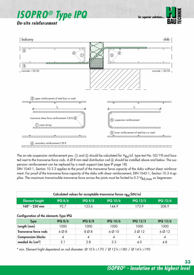
ISOPROreg - Insulation at the highest level
for superior solutions
33
balcony slab
upper reinforcement of steel bars or mesh
lower reinforcement of steel bars or mesh
transverse shear force reinforcement 2 Oslash 8
insert stirrup
ls ls
a
b
c
d
d
a
c
d
b
suspension reinforcemente
ed
secondary reinforcement 2 Oslash 8
concrete concrete
The on-site suspension reinforcement pos and should be calculated for VRd (cf type test No 0519) and loca-ted next to the transverse force rods A Oslash 8 mm steel distribution rod should be installed above and below The sus-pension reinforcement can be replaced by a mesh support (see type IP page 18)DIN 1045-1 Section 1033 applies to the proof of the transverse force capacity of the slabs without shear reinforce-ment For proof of the transverse force capacity of the slabs with shear reinforcement DIN 1045-1 Section 1034 ap-plies The maximum transmissible transverse force across the joints must be limited to 03 VRdmax zu begrenzen
ISOPROreg Type IPQOn-site reinforcement
Calculated values for acceptable transverse forces vRd [kNm]
Element height IPQ 86 IPQ 88 IPQ 106 IPQ 125 IPQ 126
160 - 250 mm 927 1236 1449 1739 2089
Type IPQ 86 IPQ 88 IPQ 106 IPQ 125 IPQ 126Length [mm] 1000 1000 1000 1000 1000
Transverse force rods 6 Oslash 8 8 Oslash 8 6 Oslash 10 5 Oslash 12 6 Oslash 12
Compression blocks 4 4 4 4 4needed As [cmsup2] 21 28 33 40 48
Configuration of the elements Type IPQ
min Element hight depentend on rod diameter Oslash 10 h ge170 Oslash 12 h ge180 Oslash 14 h ge190
wwwh-baucom34
ISOPROreg Type IPQS 2Construction and dimensions
balcony slab
balcony slab
Calculated values for acceptable transverse forces VRd [kN]
Element height IPQS 62 IPQS 82 IPQS 102 IPQS 122 IPQS 142
160 - 250 mm 174 309 483 695 947
Dimensioning table - Type IPQS2 for concrete gege C2025
Type IPQS 62 IPQS 82 IPQS 102 IPQS 122 IPQS 142
Element length [mm] 300 300 300 300 300
Transverse force rods 2 Oslash 6 2 Oslash 8 2 Oslash 10 2 Oslash 12 2 Oslash 14
Compression rods 2 Oslash 10 2 Oslash 10 3 Oslash 10 4 Oslash 12 4 Oslash 14needed As [cmsup2] 040 071 111 160 218
Configuration of the elements Type IPQS2
min Element height dependent on rod diameter Oslash 10 h ge170 Oslash 12 h ge180 Oslash 14 h ge190
IPQS 82 495mmIPQS102 615mmIPQS122 740mmIPQS 142 860mm
IPQS 62
IPQS 82 495mmIPQS102 615mmIPQS122 740mmIPQS 142 860mm
ISOPROreg - Insulation at the highest level
for superior solutions
35
Calculated values for acceptable transverse forces VRd [kN]
Element height IPQS 63 IPQS 83 IPQS 103 IPQS 123 IPQS 143
160 - 250 mm 261 464 724 1043 1420
Dimensioning table - Type IPQS3 for concrete gege C2025
Type IPQS 63 IPQS 83 IPQS 103 IPQS 123 IPQS 143
Element length [mm] 400 400 400 400 400
Transverse force rods 3 Oslash 6 3 Oslash 8 3 Oslash 10 3 Oslash 12 3 Oslash 14
Compression rods 2 Oslash 10 3 Oslash 10 4 Oslash 12 5 Oslash 12 6 Oslash 14needed As [cmsup2] 060 107 167 240 327
Configuration of the elements Type IPQS3
balcony slab
balcony slab
ISOPROreg Type IPQS 3Construction and dimensionsn
IPQS 83 495mmIPQS103 615mmIPQS123 740mmIPQS 143 860mm
IPQS 63
IPQS 83 495mmIPQS103 615mmIPQS123 740mmIPQS 143 860mm
min Element height dependent on rod diameter Oslash 10 h ge170 Oslash 12 h ge180 Oslash 14 h ge190
wwwh-baucom36
ISOPROreg Type IPQQConstruction and dimensions
1000
1000
balcony balconyslab slab
180 80 150 80165 165
370 80 80150
IPQQ 86 495 mmIPQQ 106 615 mmIPQQ 126 740 mm
IPQQ 86 495 mmIPQQ 106 615 mmIPQQ 126 740 mm
IPQQ 64 IPQQ 66IPQQ 68 IPQQ 610
Calculated values for acceptable transverse forces vRd [kNm]
Element height IPQQ 64 IPQQ 66 IPQQ 68 IPQQ 610 IPQQ 86 IPQQ 106 IPQQ 126
160 - 250 mm plusmn348 plusmn522 plusmn695 plusmn869 plusmn927 plusmn1449 plusmn2086
Type IPQQ 64 IPQQ 66 IPQQ 68 IPQQ 610 IPQQ 86 IPQQ 106 IPQQ 126Element length [mm] 500 + 500 500 + 500 500 + 500 500 + 500 500 + 500 500 + 500 500 + 500Transverse force rods 2x4 Oslash 6 2x6 Oslash 6 2x8 Oslash 6 2x10 Oslash 6 2x6 Oslash 8 2x6 Oslash 10 2x6 Oslash 12
Compression rods 4 Oslash 10 4 Oslash 10 6 Oslash 10 6 Oslash 10 6 Oslash 10 10 Oslash 10 10 Oslash 12needed As [cmsup2] 080 120 160 200 213 333 480
Dimensioning table - Type IPQQ for concrete gege C2025
Configuration of the elements Typ IPQQ
Top view
Section
min Element height dependent on rod diameter Oslash 10 h ge170 Oslash 12 h ge180 Oslash 14 h ge190
ISOPROreg - Insulation at the highest level
for superior solutions
37
ISOPROreg Type IPQQOn-site reinforcement
balcony slab
upper reinforcement of steel bars or mesh
lower reinforcement of steel bars or mesh
ls ls
b
c
a
c
d
b
insert stirrupa
d
dinsert stirrupa
ad
d
secondary reinforcement 2 Oslash 8
concrete concrete
secondary reinforcement 2 Oslash 8
The on-site suspension reinforcement pos should be calculated for VRd and located next to the transverse forcerods A Oslash 8 mm steel distribution rod should be installed above and below DIN 1045-1 Section 1033 applies to the proof of the transverse force capacity of the slabs without shear reinforce-ment For proof of the transverse force capacity of the slabs with shear reinforcement DIN 1045-1 Section 1034 ap-plies The maximum transmissible transverse force across the joints must be limited to 03 VRdmax
wwwh-baucom38
ISOPROreg Type IPQQS 2Construction and dimensions
balcony slab
balcony slab
Calculated values for acceptable transverse forces VRd [kN]
Element height IPQQS 62 IPQQS 82 IPQQS 102 IPQQS 122 IPQQS 142
160 - 250 mm plusmn174 plusmn309 plusmn483 plusmn695 plusmn947
Dimensioning table - Type IPQQS2 for concrete gege C2025
Type IPQQS 62 IPQQS 82 IPQQS 102 IPQQS 122 IPQQS 142
Element length [mm] 300 300 300 300 300
Transverse force rods 2x 2 Oslash 6 2x 2 Oslash 8 2x 2 Oslash 10 2x 2 Oslash 12 2x 2 Oslash 14
Compression rods 2 Oslash 10 2 Oslash 10 3 Oslash 10 4 Oslash 12 4 Oslash 14needed As [cmsup2] 040 071 111 160 218
Configuration of the elements Type IPQQS2
IPQQS 82 495mmIPQQS 102 615mmIPQQS 122 740mmIPQQS 142 860mm
IPQQS 62
IPQQS 82 495mmIPQQS 102 615mmIPQQS 122 740mmIPQQS 142 860mm
min Element height dependent on rod diameter Oslash 10 h ge170 Oslash 12 h ge180 Oslash 14 h ge190
ISOPROreg - Insulation at the highest level
for superior solutions
39
ISOPROreg Type IPQQS 3Construction and dimensions
balcony slab
balcony slab
Calculated values for acceptable transverse forces VRd [kN]
Element height IPQQS 63 IPQQS 83 IPQQS 103 IPQQS 123 IPQQS 143
160 - 250 mm plusmn261 plusmn464 plusmn724 plusmn1043 plusmn1420
Dimensioning table - Type IPQQS3 for concrete gege C2025
Type IPQQS 63 IPQQS 83 IPQQS 103 IPQQS 123 IPQQS 143
Element length [mm] 400 400 400 400 400
Transverse force rods 2x 3 Oslash 6 2x 3 Oslash 8 2x 3 Oslash 10 2x 3 Oslash 12 2x 3 Oslash 14
Compression rods 2 Oslash 10 3 Oslash 10 4 Oslash 12 5 Oslash 12 6 Oslash 14needed As [cmsup2] 060 107 167 240 327
Configuration of the elements Type IPQQS3
min Element height dependent on rod diameter Oslash 10 h ge170 Oslash 12 h ge180 Oslash 14 h ge190 alternatively in Element length 500 mm available
IPQQS 83 495mmIPQQS 103 615mmIPQQS 123 740mmIPQQS 143 860mm
IPQQS 63
IPQQS 83 495mmIPQQS 103 615mmIPQQS 123 740mmIPQQS 143 860mm
wwwh-baucom40
ISOPROreg Type IPTDConstruction and dimensions
IPTD IPTD
inset balcony
30
balcony slab
Top view
Section
Example
Table of Dimensions ndash Type IPTD [length in mm]
TypeTension rod Transverse force rod Compression rod Supplemental transverse force
ZL QL DL Q10L Q12LIPTD 126 820 497 820 617 742IPTD 127 820 497 820 617 742IPTD 1210 820 497 820 617 742IPTD 1212 820 497 820 617 742IPTD 1410 960 497 960 617 742
ISOPROreg - Insulation at the highest level
for superior solutions
41
ISOPROreg Type IPTDOn-site reinforcement
balcony slab
upper reinforcement of steelbars or mesh
lower reinforcement of steelbars or mesh
secondary reinforcement 2 Oslash 8
secondary reinforcement 2 Oslash 8
insert stirrup
ls ls
AA
a
b
c
d
d
a
c
d
b
lower reinforcement of steelbars or meshc
upper reinforcement of steelbars or meshb
d
insert stirrupee
b
c
a
a
Section A - A
ISOPRO transverse force rods ISOPRO compression rods
ISOPRO transverse force rods ISOPRO tension rods
d
concrete concrete
The on-site suspension reinforcement pos should be calculated for VRd and located next to the transverse forcerods A Oslash 8 mm steel distribution rod should be installed above and below DIN 1045-1 Section 1033 applies to the proof of the transverse force capacity of the slabs without shear reinforce-ment For proof of the transverse force capacity of the slabs with shear reinforcement DIN 1045-1 Section 1034 ap-plies The maximum transmissible transverse force across the joints must be limited to 03 VRdmax
wwwh-baucom42
ISOPROreg Type IPTDDimensioning table for concrete gege C2025
Plate thickness [mm] withreference to cv [mm] Rated values for moment loading mRd [kNmm]
30 35 IPTD 126IPTD 126
Q10IPTD 126
Q12IPTD 127
IPTD 127Q10
IPTD 127Q12
IPTD 1210
- 160 plusmn 145 - - plusmn 182 - - plusmn 253160 - plusmn 154 - - plusmn 193 - - plusmn 269- 170 plusmn 162 plusmn 146 - plusmn 204 plusmn 187 - plusmn 284
170 - plusmn 171 plusmn 154 - plusmn 214 plusmn 197 - plusmn 299- 180 plusmn 180 plusmn 162 plusmn 145 plusmn 225 plusmn 208 plusmn 190 plusmn 314
180 - plusmn 189 plusmn 170 plusmn 152 plusmn 236 plusmn 218 plusmn 199 plusmn 330- 190 plusmn 197 plusmn 178 plusmn 159 plusmn 247 plusmn 228 plusmn 209 plusmn 345
190 - plusmn 206 plusmn 186 plusmn 166 plusmn 258 plusmn 238 plusmn 218 plusmn 360- 200 plusmn 215 plusmn 194 plusmn 173 plusmn 269 plusmn 248 plusmn 227 plusmn 375
200 - plusmn 223 plusmn 202 plusmn 180 plusmn 280 plusmn 258 plusmn 236 plusmn 391- 210 plusmn 232 plusmn 209 plusmn 187 plusmn 291 plusmn 268 plusmn 246 plusmn 406
210 - plusmn 241 plusmn 217 plusmn 194 plusmn 302 plusmn 278 plusmn 255 plusmn 421- 220 plusmn 250 plusmn 225 plusmn 201 plusmn 313 plusmn 288 plusmn 264 plusmn 437
220 - plusmn 258 plusmn 233 plusmn 208 plusmn 324 plusmn 298 plusmn 273 plusmn 452- 230 plusmn 267 plusmn 241 plusmn 215 plusmn 335 plusmn 308 plusmn 283 plusmn 467
230 - plusmn 276 plusmn 249 plusmn 222 plusmn 346 plusmn 318 plusmn 292 plusmn 482- 240 plusmn 285 plusmn 257 plusmn 229 plusmn 357 plusmn 328 plusmn 301 plusmn 498
240 - plusmn 293 plusmn 265 plusmn 236 plusmn 368 plusmn 339 plusmn 310 plusmn 513- 250 plusmn 302 plusmn 272 plusmn 243 plusmn 379 plusmn 349 plusmn 320 plusmn 528
250 - plusmn 311 plusmn 280 plusmn 250 plusmn 390 plusmn 359 plusmn 329 plusmn 543
Rated values for transverse force loading vRd [kNm]
h = 160 - 250 [mm ] plusmn 415 plusmn 762 plusmn 1098 plusmn 415 plusmn 762 plusmn 1098 plusmn 415
Type IPTD 126 IPTD 126Q10
IPTD 126Q12
IPTD 127 IPTD 127Q10
IPTD 127Q12
IPTD 1210
Element lenght [mm] 500 + 500 500 + 500 500 + 500 500 + 500 500 + 500 500 + 500 500 + 500
Tension rods 6 Oslash 12 6 Oslash 12 6 Oslash 122 Oslash 10 + 6 Oslash 12
2 Oslash 10 + 6 Oslash 12
2 Oslash 10 +6 Oslash 12
10 Oslash 12
Transverse forcerods
2x4 Oslash 8 2x4 Oslash 10 2x4 Oslash 12 2x4 Oslash 8 2x4 Oslash 10 2x4 Oslash 12 2x4 Oslash 8
Compression rods 6 Oslash 12 6 Oslash 12 6 Oslash 122 Oslash 10 + 6 Oslash 12
2 Oslash 10 +6 Oslash 12
2 Oslash 10 +6 Oslash 12
10 Oslash 12
Configuration of the elements Type IPTD
ISOPROreg - Insulation at the highest level
for superior solutions
43
ISOPROreg Type IPTDDimensioning table for concrete gege C2025
Rated values for moment loading mRd [kNmm]
IPTD 1210Q10
IPTD 1210Q12
IPTD 1212IPTD 1212
Q10IPTD 1212
Q12IPTD 1410
IPTD 1410Q10
IPTD 1410Q12
- - plusmn 307 - - plusmn 349 - -- - plusmn 326 - - plusmn 371 - -
plusmn 268 - plusmn 345 plusmn 328 - plusmn 392 plusmn 377 -plusmn 282 - plusmn 363 plusmn 346 - plusmn 414 plusmn 397 -plusmn 297 plusmn 279 plusmn 382 plusmn 364 plusmn 346 plusmn 436 plusmn 418 plusmn 401plusmn 311 plusmn 293 plusmn 400 plusmn 381 plusmn 363 plusmn- 457 plusmn 439 plusmn 421plusmn 325 plusmn 306 plusmn 419 plusmn 399 plusmn 380 plusmn 479 plusmn 459 plusmn 441plusmn 340 plusmn 320 plusmn 437 plusmn 417 plusmn 397 plusmn 500 plusmn 480 plusmn 461plusmn 354 plusmn 333 plusmn 456 plusmn 434 plusmn 414 plusmn 522 plusmn 501 plusmn 480plusmn 369 plusmn 347 plusmn 474 plusmn 452 plusmn 430 plusmn 543 plusmn 522 plusmn 500plusmn 383 plusmn 361 plusmn 493 plusmn 470 plusmn 447 plusmn 565 plusmn 542 plusmn 520plusmn 397 plusmn 374 plusmn 511 plusmn 487 plusmn 464 plusmn 587 plusmn 563 plusmn 540plusmn 412 plusmn 388 plusmn 530 plusmn 505 plusmn 481 plusmn 608 plusmn 584 plusmn 560plusmn 426 plusmn 401 plusmn 548 plusmn 523 plusmn 498 plusmn 630 plusmn 604 plusmn 580plusmn 440 plusmn 415 plusmn 567 plusmn 540 plusmn 515 plusmn 351 plusmn 625 plusmn 600plusmn 455 plusmn 428 plusmn 585 plusmn 558 plusmn 531 plusmn 673 plusmn 646 plusmn 619plusmn 469 plusmn 442 plusmn 604 plusmn 576 plusmn 548 plusmn 694 plusmn 666 plusmn 639plusmn 484 plusmn 455 plusmn 622 plusmn 593 plusmn 565 plusmn 716 plusmn 687 plusmn 659plusmn 498 plusmn 469 plusmn 641 plusmn 611 plusmn 582 plusmn 737 plusmn 708 plusmn 679plusmn 512 plusmn 483 plusmn 659 plusmn 629 plusmn 599 plusmn 759 plusmn 728 plusmn 699
Rated values for transverse force loading vRd [kNm]
plusmn 762 plusmn 1098 plusmn 415 plusmn 762 plusmn 1098 plusmn 415 plusmn 762 plusmn 1098
IPTD 1210Q10
IPTD 1210Q12
IPTD 1212 IPTD 1212Q10
IPTD 1212Q12
IPTD 1410 IPTD 1410Q10
IPTD 1410Q12
500 + 500 500 + 500 500 + 500 500 + 500 500 + 500 500 + 500 500 + 500 500 + 500
10 Oslash 12 10 Oslash 12 12 Oslash 12 12 Oslash 12 12 Oslash 12 10 Oslash 14 10 Oslash 14 10 Oslash 14
2x4 Oslash 10 2x4 Oslash 12 2x4 Oslash 8 2x4 Oslash 10 2x4 Oslash 12 2x4 Oslash 8 2x4 Oslash 10 2x4 Oslash 12
10 Oslash 12 10 Oslash 12 12 Oslash 12 12 Oslash 12 12 Oslash 12 10 Oslash 14 10 Oslash 14 10 Oslash 14
wwwh-baucom44
ISOPROreg Type IPQZConstruction and dimensions
300
40
0
300
40
0
balcony slab
balcony slab
For restraint-free support with an IPQZ element it should be opposed by an IPQS element Both elements should bereinforced by a tieback which corresponds in diameter and rod count to the IPQS and IPQZAn on-site stirrup reinforcement is required to connect IPQS to the floor
Calculated values for acceptable transverse forces VRd [kN]
Element height IPQZ 62 IPQZ 82 IPQZ 102 IPQZ 122 IPQZ 142
160 - 250 mm 174 309 483 695 947
IPQZ 63 IPQZ 83 IPQZ 103 IPQZ 123 IPQZ 143
160 - 250 mm 261 464 724 1043 1420
Dimensioning table ndash Type IPQZ for concrete ge C2025
Type IPQZ 62 IPQZ 82 IPQZ 102 IPQZ 122 IPQZ 142Element lenght [mm] 300 300 300 300 300
Transverse force rods 2 Oslash 6 2 Oslash 8 2 Oslash 10 2 Oslash 12 2 Oslash 14
Configuration of the elements
Type IPQZ 63 IPQZ 83 IPQZ 103 IPQZ 123 IPQZ 143Element length [mm] 400 400 400 400 400
Transverse force rods 3 Oslash 6 3 Oslash 8 3 Oslash 10 3 Oslash 12 3 Oslash 14
min Element height dependent on rod diameter Oslash 10 h ge170 Oslash 12 h ge180 Oslash 14 h ge190
IPQZ 82 83 495mmIPQZ102 103 615mmIPQZ122 123 740mmIPQZ 142 143 860mm
IPQZ 82 83 495mmIPQZ102 103 615mmIPQZ122 123 740mmIPQZ 142 143 860mm
IPQZ 62 63
ISOPROreg - Insulation at the highest level
for superior solutions
45
ISOPROreg Type IPQZOn-site reinforcement
Type Tieback Insert stirrup for use with
IPQZ 62 2 Oslash 6 1 Oslash 6 IPQS 62
IPQZ 82 2 Oslash 8 1 Oslash 8 IPQS 82
IPQZ 102 2 Oslash 10 1 Oslash 10 IPQS 102
IPQZ 122 2 Oslash 12 2 Oslash 8 IPQS 122
IPQZ 142 2 Oslash 14 2 Oslash 10 IPQS 142
tie roda
b
stirrup for anchering tie rodb
a
slab slabbalcony
Typ IPQZ Typ IPQS
Type Tieback Insert stirrup for use with
IPQZ 63 3 Oslash 6 2 Oslash 6 IPQS 63
IPQZ 83 3 Oslash 8 2 Oslash 8 IPQS 83
IPQZ 103 3 Oslash 10 2 Oslash 10 IPQS 103
IPQZ 123 3 Oslash 12 3 Oslash 8 IPQS 123
IPQZ 143 3 Oslash 14 3 Oslash 10 IPQS 143
wwwh-baucom46
ISOPROreg Type IPHConstruction and dimensions
The ISOPROreg elements type IPH which absorb horizontal forces must only be used with ISOPROreg cantilever slabs ortransverse force connections
The number of IPH elements to be used is defined by the structural engineer whereby the expansion joint spacing mustbe maintained
When using ISOPROreg IPH elements the force absorption of the line connection must be reduced by the ratio of thelength of the IPH elements to the total connection length as a percentage
independent of cvReinforcement Length of
element
HRd
Transverse force Horizontal Transverse force Horizontal
IPH 1 2 x 1 Oslash 8 - 100 mm plusmn 74 kN -IPH 2 - 1 Oslash 10 100 mm - plusmn181 kNIPH 3 2 x 1 Oslash 8 1 Oslash 10 100 mm plusmn 74 kN plusmn 181 kN
Dimensioning table ndash Type IPH for concrete gege C2025
balcony slab
balcony slab
balcony slab
balcony slab
balcony slab
balcony slab
100
100
100
250 80 250
250 80 250
250 80 250IPH 1 for absorption of horizontal forces parallel to the insulation joint
IPH 2 for absorption of horizontal forces perpendicular to the insulation joint
IPH 3 for absorption of horizontal forces parallel and perpendicular to the insulation joint
ISOPROreg - Insulation at the highest level
for superior solutions
47
ISOPROreg Type IPHOn-site reinforcement
The installation of the ISOPROreg IPH elements is analogous to the installation of the ISOPROreg cantilever slabs or trans-verse force connectionsThe number and positions of the elements are defined in the structural detail The elements must be fixed in their posi-tions
plate slab balcony slab
ls ls
lower reinforcement of steel bars or mesh
d
lower reinforcement of steel bars or mesh
upper reinforcement of steel bars or mesh
a
aa
dc
d
insert stirrup
a
b
c
secondary reinforcement Oslash 8
b
c c
insert stirrup
wwwh-baucom48
ISOPROreg Type IPAConstruction and calculation values
29
0204
0608
1012
1416
1820
2422
2628
0204
0608
1012
1416
1820
2224
2628
0 +10 +20 +30 +40 +50-10-20-30-40-50
dimensioning axis
MEd
VEd
NEd
380
60
gt160
sup3 16
0
130
Section
Mathematical model ndash Static system Interaction diagram
NRd [kN]
M Rd[kNm]
DimensionsLength of element 350 mmFascia thickness 160 ndash 240 mmHeight of element from 160 mmThickness of insulation element 60 mm
ReinforcementTension rods 3 Oslash 8Compression rods 3 Oslash 8Transverse force rods 2 x 2 Oslash 6
Calculated values for NRd = 0MRd 29 kNmelementVRd plusmn 127 kNelement
ISOPROreg - Insulation at the highest level
for superior solutions
49
ISOPROreg Type IPAOn-site reinforcement and installation instructions
400
100
aa
bc
b c
dd
e
f
gh
h
e
g
h
f
inse
rt s
tirru
ps
conn
ectio
n re
info
rcem
ent
conn
ectio
n re
info
rcem
ent
steel bar Oslash 8
upper slab reinforcement
insert stirrups 3 Oslash 8 150 mmsupplied
insert stirrup as constructive edging
lower slab reinforcement
34
160
56 59 60 60 59 56
34
Section Plan
Installation instructions1 Lay lower reinforcement including edging
2 Install ISOPROreg elements type IPA Spacing in accordance with static requirements
3 Install positions and and tie together
4 Lay upper floor reinforcement and tie together with the ISOPROreg reinforcement element
5 Concrete the floor slab Ensure safe positioning
6 Attach the on-site insulation between the ISOPROreg elements
7 Lay the fascia reinforcement and including edging and tie together with the ISOPROreg elements
supplied insulation
Type IPAType IPA
350e = separation of elements
gt 80
gt 16
0
Spacing of the elements Spacing of expansion joints
Expansion joint spacing e le 78 mAbove corner e2 le 35 m
The parapet must be verified as being a continuous supporte = spacing of the elements in accordance with static requirements
wwwh-baucom50
+5 +15 +25 +35-5-15-25-35
05
10
15
0
MEd
NEdVEd
MRdVRd
dimensioning axis
ISOPROreg Type IPFConstruction and calculation values
42034
0
60
100
Section
Mathematical model ndash Static system Interaction diagram
DimensionsLength of element 350 mmHeight of element from 160 mmThickness of insulation element 60 mm
ReinforcementTension rods 3 Oslash 6Compression rods 3 Oslash 6Transverse force rods 2 Oslash 6
Calculated values for NRd = 0MRd plusmn 15 kNmelementVRd + 127 kNelement
NRd [kN]
M Rd[kN
m]
VRd = 127 kN
ISOPROreg - Insulation at the highest level
for superior solutions
51
ISOPROreg Type IPFOn-site reinforcement and installation instructions
b
a insert stirrup min Oslash 6 150 mm
upper slab reinforcement
ac
b
e
d
c lower slab reinforcement
est
eel b
ar Oslash
8
d2
inse
rt s
tirru
p m
in Oslash
6
150
mm
3333
56 59 60 60 59 56
160
350
Section
Plan
Installation instructions1 Lay lower reinforcement including edging
2 Install ISOPROreg elements type IPA Spacing in accordance with static requirements
3 Install positions and and tie together
4 Lay upper floor reinforcement and tie together with the ISOPROreg reinforcement element
5 Concrete the floor slab Ensure safe positioning
6 Attach the on-site insulation between the ISOPROreg elements
7 Lay the fascia reinforcement and including edging and tie together with the ISOPROreg elements
350
60
Type IPF Type IPF
e = separation of elements
supplied insulation
parapet
Spacing of the elements
Spacing of expansion joints
Expansion joint spacing e le 78 mAbove corner e2 le 35 m
The parapet must be verified as beinga continuous support e = spacing of the elements in accor-dance with static requirements
wwwh-baucom52
ISOPROreg Type IPOConstruction and calculation values
23 lK
+PRd
+HEd
lK
sliding film
reinforcedconcrete console
soft-fibre panel
sup3 18
0
sup3 150 60
725
130 60 535
350
sliding film
reinforcedconcrete console
soft-fibre panelsup3
180
sup3 150 60
725
130 60 535
350
Section
Plan Mathematical modelStatic system
DimensionsLength of element 350 mmHeight of element from 180 mmThickness of insulation element 60 mm
ReinforcementTension rods 3 Oslash 6Compression rods 3 Oslash 8Transverse force rods 2 Oslash 10
for Hed = 0 PRd plusmn 171 kNmelement max HRd + 184 kNelement
0 2 4 6 8 10 12 14 16 20 22 Horizontal force HEd [kN]
25
15
10
5
0
P Rd[kN] concrete gege C2530
concrete gege C2025
PRd = 23
PRd = 10
HEd
= 18
4
HEd
= 23
1
ISOPROreg - Insulation at the highest level
for superior solutions
53
ISOPROreg Type IPOOn-site reinforcement and installation instructions
slab
a
a
bde
b
c
c upper reinforcement of steel bars or mesh
lower reinforcement of steel bars or mesh
insert stirrupde
long
itudi
nal r
einf
orce
men
t
clos
ed s
tirru
p
concrete
concrete
Section Installation instructions
1 Lay lower reinforcement including edging
2 Install ISOPROreg elements type IPO Spacingin accordance with static requirements
3 Lay upper floor reinforcement and tie to-gether with the ISOPROreg reinforcement ele-ment
4 Attach the on-site insulation between the ISO-PROreg elements
5 Lay the console reinforcement and andtie together with the ISOPROreg elements Thefloor edge beam must be designed as a con-tinuous support
6 As far as practical the console and the floorshould be concreted simultaneously Ensuresecure positioning
reinforced concrete joist
ISOPRO Type IPO ISOPRO Type IPO
supplied insulation
e = separation of elements350
Spacing of the elements Spacing of expansion joints
Expansion joint spacing e le 78 mAbove corner e2 le 35 m
The parapet must be verified as being a continuous support e = spacing of the elements in accordance with static requirements
wwwh-baucom54
ISOPROreg Type IPSConstruction and calculation values
80
5050
80 ZL
balcony slab plate slab
wall
console
tension rod
transverse force bars
compression strut
ZL
QL
QL
DL
80
DL
100100
BSt 500 Nr Wst Nr 14571
BSt 500 Nr Wst Nr 14571
BSt 500 S
BSt 500 S
Section
80
5050
80 ZL
balcony slab plate slab
wall
console
tension rod
transverse force bars
compression strut
ZL
QL
QL
DL
80
DL
100100
BSt 500 Nr Wst Nr 14571
BSt 500 Nr Wst Nr 14571
BSt 500 S
BSt 500 S
Dimensions - Type IPS [length in mm]
Type Tension rod Transverse forcerod
Compressionrod
ZL QL DLIPS 1 690 500 430IPS 2 820 620 500IPS 3 960 745 570IPS 4 1550 865 600
Dimensioning table for concrete gege C2025Element hight 400 mm IPS 1 IPS 2 IPS 3 IPS 4
moment MRd [kNm] 221 294 375 624
transverse forces VRd [kN] 213 333 480 653
Type IPS 1 IPS 2 IPS 3 IPS 4
Element width [mm] 220 220 220 220
Tension rods 3 Oslash 10 3 Oslash 12 3 Oslash 14 4 Oslash 14
Transverse force rods 2 Oslash 8 2 Oslash 10 2 Oslash 12 2 Oslash 14
Compression rods 3 Oslash 12 3 Oslash 14 3 Oslash 16 3 Oslash 20
Other designs and dimensions are available on requestThe bonding area I underlies the determination of the anchoring lengths However if required the reinforcement rods can also be designed for bonding area II
Configuration of the elements
ISOPROreg - Insulation at the highest level
for superior solutions
55
ISOPROreg Type IPSOn-site reinforcement and installation instructions
wall plate reinforcement to structural calculations
tension rod
transverse force bars
compression strut
a
b
c
d
d
a
b
a closed stirrup
edging
c suspension reinforcementconcrete concrete
Installation instructions
1 Lay wall plate reinforcement to meet structural requirements2 Insert ISOPROreg element type IPS and tie together with the wall
reinforcement Transverse reinforcement in overlap zone in accordance with DIN 1045-1
3 Install and tie together beam reinforcement and according to structural calculations Pos edging in accordance withDIN 1045-1 Pos installed as a closed stirrup to avoid shearing
4 When concreting make sure that both sides are uniformly filled and compacted
5 Formwork offset for the beam in accordance with structural calculations
wall plate reinforcement to structural calculations
tension rod
transverse force bars
compression strut
a
b
c
d
d
a
b
a closed stirrup
edging
c suspension reinforcementconcrete concrete
80
b b
plate slab
Type IPS
wal
l pla
te
Type IPS wal
l pla
te
balcony slab
supplied insulation
Configuration of the elements Expansion joint spacing
TypeJoint spacing [m]
e
IPS 1 113
IPS 2 101
IPS 3 92
IPS 4 80
For corner constructions the maximumrod leg length is e2
wwwh-baucom56
ISOPROreg Type IPWConstruction and calculation values
ZL ZL80
420 420
QL QL
DL DL
290290
low
er s
ectio
n12
50ce
ntre
sec
tion
uppe
r se
ctio
n25
0
h =
150
- 3
50
m
80
balcony
balcony slab
slab
exte
rnal
wal
l
inte
rnal
wal
l
horizontal transverse force bars
horizontal transverse force bars
upper section bht in mm150-250 250 80
lower section bht in mm150-250 1250 80
Section
Table of Dimensions Type IPW [length in mm]
Type
Tension rod Transverseforce rod
Compressionrod
ZL QL DLIPW 1 600 423 270IPW 2 790 563 335IPW 3 980 653 410IPW 4 1170 783 470
Element width b = 150 ndash 250 mmElement height h = 150 ndash 350 mInsulation material thickness t = 80 mm
Dimensioning table for concrete gege C2025Calculated values for acceptable moments MRdy [kNm]
Element height [m] IPW 1 IPW 2 IPW 3 IPW 415 ndash 20 537 918 1169 154420 ndash 25 737 1267 1614 2132
gt 25 937 1616 2059 2720Calculated values for acceptable transverse forces [kN]
vRdz [kN] 412 622 1066 1535vRdy [kN] plusmn137 plusmn137 plusmn137 plusmn137
Type IPW 1 IPW 2 IPW 3 IPW 4Element height [m] ge150 ge150 ge150 ge150Tension rods 4 Oslash 6 4 Oslash 8 4 Oslash 10 4 Oslash 12Transverse force rods Qz 6 Oslash 6 6 Oslash 8 6 Oslash 10 6 Oslash 12Transverse force rods Qy 2 x 2 Oslash 6 2 x 2 Oslash 6 2 x 2 Oslash 6 2 x 2 Oslash 6Compression rods 6 Oslash 8 6 Oslash 10 6 Oslash 12 6 Oslash 14
Configuration of the elements
Moment effects from wind loading are absorbed bythe stiffening effect of the balcony slab
MRdz = 0
Bonding area II underlies the determination of theoverlap lengths On request the anchoring lengthscan also be dimensioned for bonding area I Designsand dimensions deviating from the standard ele-ments are available on request
ISOPROreg - Insulation at the highest level
for superior solutions
57
ISOPROreg Type IPWOn-site reinforcement and installation instructions
MRdz
VRdz VRdy
x
z
y
MRdy
Mathematical model ndash Static system
balcony slab
balcony slab
steel
mes
h re
info
rcem
ent
a
steel
mes
h re
info
rcem
ent
b
e connection reinforcementto structural calculations
f
insert stirrupas constructive edging c
c
d steel bar min 2 Oslash 8
concrete sup3 2025
exte
rnal
wal
l
inte
rnal
wal
l
insert stirrupas constructive edging
connection reinforcementto structural calculations
a bc c
d
d
steel bar min 2 Oslash 8
steel bar min 2 Oslash 8
insert stirrupinsert stirrupsteel mesh reinforcement steel mesh reinforcement
80
wall p
late
wall p
late
balcony slab
plate slab
Type IPWsupplied insulation
Type IPW
b b
e e e
Configuration of the elements
Installation instructions
1 Position internal wall reinforcement 2 Attach the constructive edging inter-
nally (insert stirrup)3 Starting at the bottom assemble the in-
dividual ISOPROreg elements type IPWand tie together with the wall reinforce-ment
4 Erect and internally and tie to-gether
5 Position the external wall reinforce-ments and in accordancewith structural design and tie to theISOPROreg elements
6 When concreting pay particular atten-tion to the positional security of the ele-ments It is recommended to fill andcompact both wall plates at the sametime
wwwh-baucom58
ISOPROreg
Approvals and Type testing
Approvals
ISOPRO Type IP Z-157-244ISOPRO Type IPT Z-157-243
Type testing
ISOPRO Type IP Test No 0517ISOPRO Type IPT Test No 0518ISOPRO Type IPQ Test No 0519
ISOPROreg - Insulation at the highest level
for superior solutions
59
ISOPROreg
Tender
___________________________________________________________________________
Scope Application area DIN 276013 Concrete and reinforced concrete Floor constructions
Structural installations__________________________________________________________________________________
ISOPROreg supporting and thermally insulating connection elements
01 supporting the balcony slab using ISOPROreg elements from H-BAU Technik GmbH02 required for installation03 m Type IP cv = mm h = mm04 m Type IPQ cv = mm h = mm05 part Type cv = mm h = mm
Special fabrication according to the following description
06 for thermal separation of the concrete07 for the storey floors pos 08 for the roofing pos 09 for 10 and11 for the balcony slap pos 12 for the loggia slab pos 13 for the cantilever slab pos 14 for the 15 in fire protection construction class F9016 the bonding is made in the reinforcement of pos and pos 17 deliver18 deliver install and bond with the connection reinforcement19 only install and bond with the connection reinforcement delivery provided20 the installation is made in accordance with instructions from
H-BAU Technik GmbHAm Guumlterbahnhof 2079771 Klettgau-ErzingenGermanyTel +49 (0) 77 42 92 15-20Fax +49 (0) 77 42 92 15-90
21 in accordance with the detail and reinforcement drawings no 22 material 23 wages 24 unit price
25 total price
wwwh-baucom60
NOTES
ISOPROreg - Insulation at the highest level
for superior solutions
61
NOTES
wwwh-baucom
Concreting with system
ISOPROreg
KESIIRAPIDOBATreg
JSDHEDFERBOXreg
BOXFERreg
GRIPRIPreg
PENTAFLEXreg
RIPINOXreg
WARMBORDreg
SCHALBORDreg
ZEMBORDreg
SCHALL-ISO ACCESSORIES
H-BAU Technik GmbHAm Guumlterbahnhof 20D-79771 Klettgau-ErzingenTel + 49 (0) 7742 92 15-20Fax + 49 (0) 7742 92 15-90infoklettgauh-baude
Produktion Nord-OstBrandenburger StraszligeD-14641 WachowTel + 49 (0) 3 3239 775-20Fax + 49 (0) 3 3239 775-90infoberlinh-baude
Balcony insulation elementsLifting anchorsShuttering tubesPush-in pegsReinforcement connectorsReinforcement connectorsMasonry connectorsSealing technologyRustproof stainless steelStop end panelsStop end panelsStop end panelsSound insulation elementsSpacers
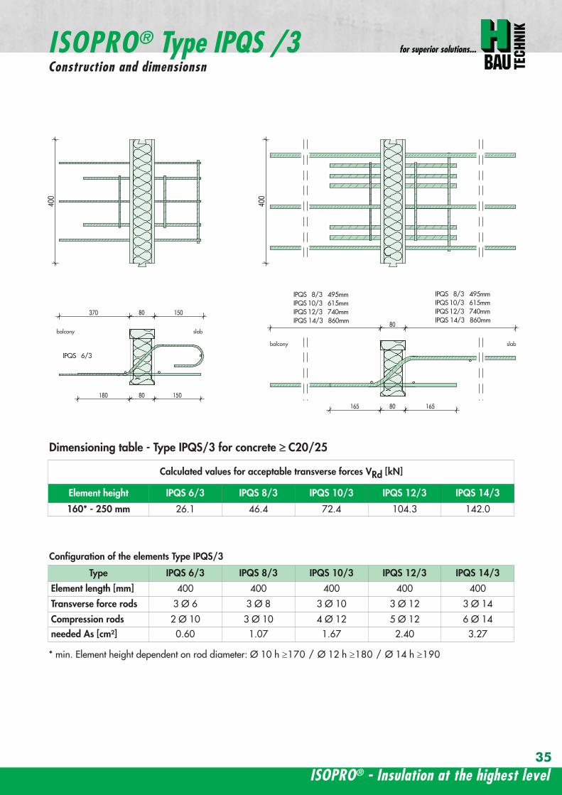
ISOPROreg - Insulation at the highest level
for superior solutions
35
Calculated values for acceptable transverse forces VRd [kN]
Element height IPQS 63 IPQS 83 IPQS 103 IPQS 123 IPQS 143
160 - 250 mm 261 464 724 1043 1420
Dimensioning table - Type IPQS3 for concrete gege C2025
Type IPQS 63 IPQS 83 IPQS 103 IPQS 123 IPQS 143
Element length [mm] 400 400 400 400 400
Transverse force rods 3 Oslash 6 3 Oslash 8 3 Oslash 10 3 Oslash 12 3 Oslash 14
Compression rods 2 Oslash 10 3 Oslash 10 4 Oslash 12 5 Oslash 12 6 Oslash 14needed As [cmsup2] 060 107 167 240 327
Configuration of the elements Type IPQS3
balcony slab
balcony slab
ISOPROreg Type IPQS 3Construction and dimensionsn
IPQS 83 495mmIPQS103 615mmIPQS123 740mmIPQS 143 860mm
IPQS 63
IPQS 83 495mmIPQS103 615mmIPQS123 740mmIPQS 143 860mm
min Element height dependent on rod diameter Oslash 10 h ge170 Oslash 12 h ge180 Oslash 14 h ge190
wwwh-baucom36
ISOPROreg Type IPQQConstruction and dimensions
1000
1000
balcony balconyslab slab
180 80 150 80165 165
370 80 80150
IPQQ 86 495 mmIPQQ 106 615 mmIPQQ 126 740 mm
IPQQ 86 495 mmIPQQ 106 615 mmIPQQ 126 740 mm
IPQQ 64 IPQQ 66IPQQ 68 IPQQ 610
Calculated values for acceptable transverse forces vRd [kNm]
Element height IPQQ 64 IPQQ 66 IPQQ 68 IPQQ 610 IPQQ 86 IPQQ 106 IPQQ 126
160 - 250 mm plusmn348 plusmn522 plusmn695 plusmn869 plusmn927 plusmn1449 plusmn2086
Type IPQQ 64 IPQQ 66 IPQQ 68 IPQQ 610 IPQQ 86 IPQQ 106 IPQQ 126Element length [mm] 500 + 500 500 + 500 500 + 500 500 + 500 500 + 500 500 + 500 500 + 500Transverse force rods 2x4 Oslash 6 2x6 Oslash 6 2x8 Oslash 6 2x10 Oslash 6 2x6 Oslash 8 2x6 Oslash 10 2x6 Oslash 12
Compression rods 4 Oslash 10 4 Oslash 10 6 Oslash 10 6 Oslash 10 6 Oslash 10 10 Oslash 10 10 Oslash 12needed As [cmsup2] 080 120 160 200 213 333 480
Dimensioning table - Type IPQQ for concrete gege C2025
Configuration of the elements Typ IPQQ
Top view
Section
min Element height dependent on rod diameter Oslash 10 h ge170 Oslash 12 h ge180 Oslash 14 h ge190
ISOPROreg - Insulation at the highest level
for superior solutions
37
ISOPROreg Type IPQQOn-site reinforcement
balcony slab
upper reinforcement of steel bars or mesh
lower reinforcement of steel bars or mesh
ls ls
b
c
a
c
d
b
insert stirrupa
d
dinsert stirrupa
ad
d
secondary reinforcement 2 Oslash 8
concrete concrete
secondary reinforcement 2 Oslash 8
The on-site suspension reinforcement pos should be calculated for VRd and located next to the transverse forcerods A Oslash 8 mm steel distribution rod should be installed above and below DIN 1045-1 Section 1033 applies to the proof of the transverse force capacity of the slabs without shear reinforce-ment For proof of the transverse force capacity of the slabs with shear reinforcement DIN 1045-1 Section 1034 ap-plies The maximum transmissible transverse force across the joints must be limited to 03 VRdmax
wwwh-baucom38
ISOPROreg Type IPQQS 2Construction and dimensions
balcony slab
balcony slab
Calculated values for acceptable transverse forces VRd [kN]
Element height IPQQS 62 IPQQS 82 IPQQS 102 IPQQS 122 IPQQS 142
160 - 250 mm plusmn174 plusmn309 plusmn483 plusmn695 plusmn947
Dimensioning table - Type IPQQS2 for concrete gege C2025
Type IPQQS 62 IPQQS 82 IPQQS 102 IPQQS 122 IPQQS 142
Element length [mm] 300 300 300 300 300
Transverse force rods 2x 2 Oslash 6 2x 2 Oslash 8 2x 2 Oslash 10 2x 2 Oslash 12 2x 2 Oslash 14
Compression rods 2 Oslash 10 2 Oslash 10 3 Oslash 10 4 Oslash 12 4 Oslash 14needed As [cmsup2] 040 071 111 160 218
Configuration of the elements Type IPQQS2
IPQQS 82 495mmIPQQS 102 615mmIPQQS 122 740mmIPQQS 142 860mm
IPQQS 62
IPQQS 82 495mmIPQQS 102 615mmIPQQS 122 740mmIPQQS 142 860mm
min Element height dependent on rod diameter Oslash 10 h ge170 Oslash 12 h ge180 Oslash 14 h ge190
ISOPROreg - Insulation at the highest level
for superior solutions
39
ISOPROreg Type IPQQS 3Construction and dimensions
balcony slab
balcony slab
Calculated values for acceptable transverse forces VRd [kN]
Element height IPQQS 63 IPQQS 83 IPQQS 103 IPQQS 123 IPQQS 143
160 - 250 mm plusmn261 plusmn464 plusmn724 plusmn1043 plusmn1420
Dimensioning table - Type IPQQS3 for concrete gege C2025
Type IPQQS 63 IPQQS 83 IPQQS 103 IPQQS 123 IPQQS 143
Element length [mm] 400 400 400 400 400
Transverse force rods 2x 3 Oslash 6 2x 3 Oslash 8 2x 3 Oslash 10 2x 3 Oslash 12 2x 3 Oslash 14
Compression rods 2 Oslash 10 3 Oslash 10 4 Oslash 12 5 Oslash 12 6 Oslash 14needed As [cmsup2] 060 107 167 240 327
Configuration of the elements Type IPQQS3
min Element height dependent on rod diameter Oslash 10 h ge170 Oslash 12 h ge180 Oslash 14 h ge190 alternatively in Element length 500 mm available
IPQQS 83 495mmIPQQS 103 615mmIPQQS 123 740mmIPQQS 143 860mm
IPQQS 63
IPQQS 83 495mmIPQQS 103 615mmIPQQS 123 740mmIPQQS 143 860mm
wwwh-baucom40
ISOPROreg Type IPTDConstruction and dimensions
IPTD IPTD
inset balcony
30
balcony slab
Top view
Section
Example
Table of Dimensions ndash Type IPTD [length in mm]
TypeTension rod Transverse force rod Compression rod Supplemental transverse force
ZL QL DL Q10L Q12LIPTD 126 820 497 820 617 742IPTD 127 820 497 820 617 742IPTD 1210 820 497 820 617 742IPTD 1212 820 497 820 617 742IPTD 1410 960 497 960 617 742
ISOPROreg - Insulation at the highest level
for superior solutions
41
ISOPROreg Type IPTDOn-site reinforcement
balcony slab
upper reinforcement of steelbars or mesh
lower reinforcement of steelbars or mesh
secondary reinforcement 2 Oslash 8
secondary reinforcement 2 Oslash 8
insert stirrup
ls ls
AA
a
b
c
d
d
a
c
d
b
lower reinforcement of steelbars or meshc
upper reinforcement of steelbars or meshb
d
insert stirrupee
b
c
a
a
Section A - A
ISOPRO transverse force rods ISOPRO compression rods
ISOPRO transverse force rods ISOPRO tension rods
d
concrete concrete
The on-site suspension reinforcement pos should be calculated for VRd and located next to the transverse forcerods A Oslash 8 mm steel distribution rod should be installed above and below DIN 1045-1 Section 1033 applies to the proof of the transverse force capacity of the slabs without shear reinforce-ment For proof of the transverse force capacity of the slabs with shear reinforcement DIN 1045-1 Section 1034 ap-plies The maximum transmissible transverse force across the joints must be limited to 03 VRdmax
wwwh-baucom42
ISOPROreg Type IPTDDimensioning table for concrete gege C2025
Plate thickness [mm] withreference to cv [mm] Rated values for moment loading mRd [kNmm]
30 35 IPTD 126IPTD 126
Q10IPTD 126
Q12IPTD 127
IPTD 127Q10
IPTD 127Q12
IPTD 1210
- 160 plusmn 145 - - plusmn 182 - - plusmn 253160 - plusmn 154 - - plusmn 193 - - plusmn 269- 170 plusmn 162 plusmn 146 - plusmn 204 plusmn 187 - plusmn 284
170 - plusmn 171 plusmn 154 - plusmn 214 plusmn 197 - plusmn 299- 180 plusmn 180 plusmn 162 plusmn 145 plusmn 225 plusmn 208 plusmn 190 plusmn 314
180 - plusmn 189 plusmn 170 plusmn 152 plusmn 236 plusmn 218 plusmn 199 plusmn 330- 190 plusmn 197 plusmn 178 plusmn 159 plusmn 247 plusmn 228 plusmn 209 plusmn 345
190 - plusmn 206 plusmn 186 plusmn 166 plusmn 258 plusmn 238 plusmn 218 plusmn 360- 200 plusmn 215 plusmn 194 plusmn 173 plusmn 269 plusmn 248 plusmn 227 plusmn 375
200 - plusmn 223 plusmn 202 plusmn 180 plusmn 280 plusmn 258 plusmn 236 plusmn 391- 210 plusmn 232 plusmn 209 plusmn 187 plusmn 291 plusmn 268 plusmn 246 plusmn 406
210 - plusmn 241 plusmn 217 plusmn 194 plusmn 302 plusmn 278 plusmn 255 plusmn 421- 220 plusmn 250 plusmn 225 plusmn 201 plusmn 313 plusmn 288 plusmn 264 plusmn 437
220 - plusmn 258 plusmn 233 plusmn 208 plusmn 324 plusmn 298 plusmn 273 plusmn 452- 230 plusmn 267 plusmn 241 plusmn 215 plusmn 335 plusmn 308 plusmn 283 plusmn 467
230 - plusmn 276 plusmn 249 plusmn 222 plusmn 346 plusmn 318 plusmn 292 plusmn 482- 240 plusmn 285 plusmn 257 plusmn 229 plusmn 357 plusmn 328 plusmn 301 plusmn 498
240 - plusmn 293 plusmn 265 plusmn 236 plusmn 368 plusmn 339 plusmn 310 plusmn 513- 250 plusmn 302 plusmn 272 plusmn 243 plusmn 379 plusmn 349 plusmn 320 plusmn 528
250 - plusmn 311 plusmn 280 plusmn 250 plusmn 390 plusmn 359 plusmn 329 plusmn 543
Rated values for transverse force loading vRd [kNm]
h = 160 - 250 [mm ] plusmn 415 plusmn 762 plusmn 1098 plusmn 415 plusmn 762 plusmn 1098 plusmn 415
Type IPTD 126 IPTD 126Q10
IPTD 126Q12
IPTD 127 IPTD 127Q10
IPTD 127Q12
IPTD 1210
Element lenght [mm] 500 + 500 500 + 500 500 + 500 500 + 500 500 + 500 500 + 500 500 + 500
Tension rods 6 Oslash 12 6 Oslash 12 6 Oslash 122 Oslash 10 + 6 Oslash 12
2 Oslash 10 + 6 Oslash 12
2 Oslash 10 +6 Oslash 12
10 Oslash 12
Transverse forcerods
2x4 Oslash 8 2x4 Oslash 10 2x4 Oslash 12 2x4 Oslash 8 2x4 Oslash 10 2x4 Oslash 12 2x4 Oslash 8
Compression rods 6 Oslash 12 6 Oslash 12 6 Oslash 122 Oslash 10 + 6 Oslash 12
2 Oslash 10 +6 Oslash 12
2 Oslash 10 +6 Oslash 12
10 Oslash 12
Configuration of the elements Type IPTD
ISOPROreg - Insulation at the highest level
for superior solutions
43
ISOPROreg Type IPTDDimensioning table for concrete gege C2025
Rated values for moment loading mRd [kNmm]
IPTD 1210Q10
IPTD 1210Q12
IPTD 1212IPTD 1212
Q10IPTD 1212
Q12IPTD 1410
IPTD 1410Q10
IPTD 1410Q12
- - plusmn 307 - - plusmn 349 - -- - plusmn 326 - - plusmn 371 - -
plusmn 268 - plusmn 345 plusmn 328 - plusmn 392 plusmn 377 -plusmn 282 - plusmn 363 plusmn 346 - plusmn 414 plusmn 397 -plusmn 297 plusmn 279 plusmn 382 plusmn 364 plusmn 346 plusmn 436 plusmn 418 plusmn 401plusmn 311 plusmn 293 plusmn 400 plusmn 381 plusmn 363 plusmn- 457 plusmn 439 plusmn 421plusmn 325 plusmn 306 plusmn 419 plusmn 399 plusmn 380 plusmn 479 plusmn 459 plusmn 441plusmn 340 plusmn 320 plusmn 437 plusmn 417 plusmn 397 plusmn 500 plusmn 480 plusmn 461plusmn 354 plusmn 333 plusmn 456 plusmn 434 plusmn 414 plusmn 522 plusmn 501 plusmn 480plusmn 369 plusmn 347 plusmn 474 plusmn 452 plusmn 430 plusmn 543 plusmn 522 plusmn 500plusmn 383 plusmn 361 plusmn 493 plusmn 470 plusmn 447 plusmn 565 plusmn 542 plusmn 520plusmn 397 plusmn 374 plusmn 511 plusmn 487 plusmn 464 plusmn 587 plusmn 563 plusmn 540plusmn 412 plusmn 388 plusmn 530 plusmn 505 plusmn 481 plusmn 608 plusmn 584 plusmn 560plusmn 426 plusmn 401 plusmn 548 plusmn 523 plusmn 498 plusmn 630 plusmn 604 plusmn 580plusmn 440 plusmn 415 plusmn 567 plusmn 540 plusmn 515 plusmn 351 plusmn 625 plusmn 600plusmn 455 plusmn 428 plusmn 585 plusmn 558 plusmn 531 plusmn 673 plusmn 646 plusmn 619plusmn 469 plusmn 442 plusmn 604 plusmn 576 plusmn 548 plusmn 694 plusmn 666 plusmn 639plusmn 484 plusmn 455 plusmn 622 plusmn 593 plusmn 565 plusmn 716 plusmn 687 plusmn 659plusmn 498 plusmn 469 plusmn 641 plusmn 611 plusmn 582 plusmn 737 plusmn 708 plusmn 679plusmn 512 plusmn 483 plusmn 659 plusmn 629 plusmn 599 plusmn 759 plusmn 728 plusmn 699
Rated values for transverse force loading vRd [kNm]
plusmn 762 plusmn 1098 plusmn 415 plusmn 762 plusmn 1098 plusmn 415 plusmn 762 plusmn 1098
IPTD 1210Q10
IPTD 1210Q12
IPTD 1212 IPTD 1212Q10
IPTD 1212Q12
IPTD 1410 IPTD 1410Q10
IPTD 1410Q12
500 + 500 500 + 500 500 + 500 500 + 500 500 + 500 500 + 500 500 + 500 500 + 500
10 Oslash 12 10 Oslash 12 12 Oslash 12 12 Oslash 12 12 Oslash 12 10 Oslash 14 10 Oslash 14 10 Oslash 14
2x4 Oslash 10 2x4 Oslash 12 2x4 Oslash 8 2x4 Oslash 10 2x4 Oslash 12 2x4 Oslash 8 2x4 Oslash 10 2x4 Oslash 12
10 Oslash 12 10 Oslash 12 12 Oslash 12 12 Oslash 12 12 Oslash 12 10 Oslash 14 10 Oslash 14 10 Oslash 14
wwwh-baucom44
ISOPROreg Type IPQZConstruction and dimensions
300
40
0
300
40
0
balcony slab
balcony slab
For restraint-free support with an IPQZ element it should be opposed by an IPQS element Both elements should bereinforced by a tieback which corresponds in diameter and rod count to the IPQS and IPQZAn on-site stirrup reinforcement is required to connect IPQS to the floor
Calculated values for acceptable transverse forces VRd [kN]
Element height IPQZ 62 IPQZ 82 IPQZ 102 IPQZ 122 IPQZ 142
160 - 250 mm 174 309 483 695 947
IPQZ 63 IPQZ 83 IPQZ 103 IPQZ 123 IPQZ 143
160 - 250 mm 261 464 724 1043 1420
Dimensioning table ndash Type IPQZ for concrete ge C2025
Type IPQZ 62 IPQZ 82 IPQZ 102 IPQZ 122 IPQZ 142Element lenght [mm] 300 300 300 300 300
Transverse force rods 2 Oslash 6 2 Oslash 8 2 Oslash 10 2 Oslash 12 2 Oslash 14
Configuration of the elements
Type IPQZ 63 IPQZ 83 IPQZ 103 IPQZ 123 IPQZ 143Element length [mm] 400 400 400 400 400
Transverse force rods 3 Oslash 6 3 Oslash 8 3 Oslash 10 3 Oslash 12 3 Oslash 14
min Element height dependent on rod diameter Oslash 10 h ge170 Oslash 12 h ge180 Oslash 14 h ge190
IPQZ 82 83 495mmIPQZ102 103 615mmIPQZ122 123 740mmIPQZ 142 143 860mm
IPQZ 82 83 495mmIPQZ102 103 615mmIPQZ122 123 740mmIPQZ 142 143 860mm
IPQZ 62 63
ISOPROreg - Insulation at the highest level
for superior solutions
45
ISOPROreg Type IPQZOn-site reinforcement
Type Tieback Insert stirrup for use with
IPQZ 62 2 Oslash 6 1 Oslash 6 IPQS 62
IPQZ 82 2 Oslash 8 1 Oslash 8 IPQS 82
IPQZ 102 2 Oslash 10 1 Oslash 10 IPQS 102
IPQZ 122 2 Oslash 12 2 Oslash 8 IPQS 122
IPQZ 142 2 Oslash 14 2 Oslash 10 IPQS 142
tie roda
b
stirrup for anchering tie rodb
a
slab slabbalcony
Typ IPQZ Typ IPQS
Type Tieback Insert stirrup for use with
IPQZ 63 3 Oslash 6 2 Oslash 6 IPQS 63
IPQZ 83 3 Oslash 8 2 Oslash 8 IPQS 83
IPQZ 103 3 Oslash 10 2 Oslash 10 IPQS 103
IPQZ 123 3 Oslash 12 3 Oslash 8 IPQS 123
IPQZ 143 3 Oslash 14 3 Oslash 10 IPQS 143
wwwh-baucom46
ISOPROreg Type IPHConstruction and dimensions
The ISOPROreg elements type IPH which absorb horizontal forces must only be used with ISOPROreg cantilever slabs ortransverse force connections
The number of IPH elements to be used is defined by the structural engineer whereby the expansion joint spacing mustbe maintained
When using ISOPROreg IPH elements the force absorption of the line connection must be reduced by the ratio of thelength of the IPH elements to the total connection length as a percentage
independent of cvReinforcement Length of
element
HRd
Transverse force Horizontal Transverse force Horizontal
IPH 1 2 x 1 Oslash 8 - 100 mm plusmn 74 kN -IPH 2 - 1 Oslash 10 100 mm - plusmn181 kNIPH 3 2 x 1 Oslash 8 1 Oslash 10 100 mm plusmn 74 kN plusmn 181 kN
Dimensioning table ndash Type IPH for concrete gege C2025
balcony slab
balcony slab
balcony slab
balcony slab
balcony slab
balcony slab
100
100
100
250 80 250
250 80 250
250 80 250IPH 1 for absorption of horizontal forces parallel to the insulation joint
IPH 2 for absorption of horizontal forces perpendicular to the insulation joint
IPH 3 for absorption of horizontal forces parallel and perpendicular to the insulation joint
ISOPROreg - Insulation at the highest level
for superior solutions
47
ISOPROreg Type IPHOn-site reinforcement
The installation of the ISOPROreg IPH elements is analogous to the installation of the ISOPROreg cantilever slabs or trans-verse force connectionsThe number and positions of the elements are defined in the structural detail The elements must be fixed in their posi-tions
plate slab balcony slab
ls ls
lower reinforcement of steel bars or mesh
d
lower reinforcement of steel bars or mesh
upper reinforcement of steel bars or mesh
a
aa
dc
d
insert stirrup
a
b
c
secondary reinforcement Oslash 8
b
c c
insert stirrup
wwwh-baucom48
ISOPROreg Type IPAConstruction and calculation values
29
0204
0608
1012
1416
1820
2422
2628
0204
0608
1012
1416
1820
2224
2628
0 +10 +20 +30 +40 +50-10-20-30-40-50
dimensioning axis
MEd
VEd
NEd
380
60
gt160
sup3 16
0
130
Section
Mathematical model ndash Static system Interaction diagram
NRd [kN]
M Rd[kNm]
DimensionsLength of element 350 mmFascia thickness 160 ndash 240 mmHeight of element from 160 mmThickness of insulation element 60 mm
ReinforcementTension rods 3 Oslash 8Compression rods 3 Oslash 8Transverse force rods 2 x 2 Oslash 6
Calculated values for NRd = 0MRd 29 kNmelementVRd plusmn 127 kNelement
ISOPROreg - Insulation at the highest level
for superior solutions
49
ISOPROreg Type IPAOn-site reinforcement and installation instructions
400
100
aa
bc
b c
dd
e
f
gh
h
e
g
h
f
inse
rt s
tirru
ps
conn
ectio
n re
info
rcem
ent
conn
ectio
n re
info
rcem
ent
steel bar Oslash 8
upper slab reinforcement
insert stirrups 3 Oslash 8 150 mmsupplied
insert stirrup as constructive edging
lower slab reinforcement
34
160
56 59 60 60 59 56
34
Section Plan
Installation instructions1 Lay lower reinforcement including edging
2 Install ISOPROreg elements type IPA Spacing in accordance with static requirements
3 Install positions and and tie together
4 Lay upper floor reinforcement and tie together with the ISOPROreg reinforcement element
5 Concrete the floor slab Ensure safe positioning
6 Attach the on-site insulation between the ISOPROreg elements
7 Lay the fascia reinforcement and including edging and tie together with the ISOPROreg elements
supplied insulation
Type IPAType IPA
350e = separation of elements
gt 80
gt 16
0
Spacing of the elements Spacing of expansion joints
Expansion joint spacing e le 78 mAbove corner e2 le 35 m
The parapet must be verified as being a continuous supporte = spacing of the elements in accordance with static requirements
wwwh-baucom50
+5 +15 +25 +35-5-15-25-35
05
10
15
0
MEd
NEdVEd
MRdVRd
dimensioning axis
ISOPROreg Type IPFConstruction and calculation values
42034
0
60
100
Section
Mathematical model ndash Static system Interaction diagram
DimensionsLength of element 350 mmHeight of element from 160 mmThickness of insulation element 60 mm
ReinforcementTension rods 3 Oslash 6Compression rods 3 Oslash 6Transverse force rods 2 Oslash 6
Calculated values for NRd = 0MRd plusmn 15 kNmelementVRd + 127 kNelement
NRd [kN]
M Rd[kN
m]
VRd = 127 kN
ISOPROreg - Insulation at the highest level
for superior solutions
51
ISOPROreg Type IPFOn-site reinforcement and installation instructions
b
a insert stirrup min Oslash 6 150 mm
upper slab reinforcement
ac
b
e
d
c lower slab reinforcement
est
eel b
ar Oslash
8
d2
inse
rt s
tirru
p m
in Oslash
6
150
mm
3333
56 59 60 60 59 56
160
350
Section
Plan
Installation instructions1 Lay lower reinforcement including edging
2 Install ISOPROreg elements type IPA Spacing in accordance with static requirements
3 Install positions and and tie together
4 Lay upper floor reinforcement and tie together with the ISOPROreg reinforcement element
5 Concrete the floor slab Ensure safe positioning
6 Attach the on-site insulation between the ISOPROreg elements
7 Lay the fascia reinforcement and including edging and tie together with the ISOPROreg elements
350
60
Type IPF Type IPF
e = separation of elements
supplied insulation
parapet
Spacing of the elements
Spacing of expansion joints
Expansion joint spacing e le 78 mAbove corner e2 le 35 m
The parapet must be verified as beinga continuous support e = spacing of the elements in accor-dance with static requirements
wwwh-baucom52
ISOPROreg Type IPOConstruction and calculation values
23 lK
+PRd
+HEd
lK
sliding film
reinforcedconcrete console
soft-fibre panel
sup3 18
0
sup3 150 60
725
130 60 535
350
sliding film
reinforcedconcrete console
soft-fibre panelsup3
180
sup3 150 60
725
130 60 535
350
Section
Plan Mathematical modelStatic system
DimensionsLength of element 350 mmHeight of element from 180 mmThickness of insulation element 60 mm
ReinforcementTension rods 3 Oslash 6Compression rods 3 Oslash 8Transverse force rods 2 Oslash 10
for Hed = 0 PRd plusmn 171 kNmelement max HRd + 184 kNelement
0 2 4 6 8 10 12 14 16 20 22 Horizontal force HEd [kN]
25
15
10
5
0
P Rd[kN] concrete gege C2530
concrete gege C2025
PRd = 23
PRd = 10
HEd
= 18
4
HEd
= 23
1
ISOPROreg - Insulation at the highest level
for superior solutions
53
ISOPROreg Type IPOOn-site reinforcement and installation instructions
slab
a
a
bde
b
c
c upper reinforcement of steel bars or mesh
lower reinforcement of steel bars or mesh
insert stirrupde
long
itudi
nal r
einf
orce
men
t
clos
ed s
tirru
p
concrete
concrete
Section Installation instructions
1 Lay lower reinforcement including edging
2 Install ISOPROreg elements type IPO Spacingin accordance with static requirements
3 Lay upper floor reinforcement and tie to-gether with the ISOPROreg reinforcement ele-ment
4 Attach the on-site insulation between the ISO-PROreg elements
5 Lay the console reinforcement and andtie together with the ISOPROreg elements Thefloor edge beam must be designed as a con-tinuous support
6 As far as practical the console and the floorshould be concreted simultaneously Ensuresecure positioning
reinforced concrete joist
ISOPRO Type IPO ISOPRO Type IPO
supplied insulation
e = separation of elements350
Spacing of the elements Spacing of expansion joints
Expansion joint spacing e le 78 mAbove corner e2 le 35 m
The parapet must be verified as being a continuous support e = spacing of the elements in accordance with static requirements
wwwh-baucom54
ISOPROreg Type IPSConstruction and calculation values
80
5050
80 ZL
balcony slab plate slab
wall
console
tension rod
transverse force bars
compression strut
ZL
QL
QL
DL
80
DL
100100
BSt 500 Nr Wst Nr 14571
BSt 500 Nr Wst Nr 14571
BSt 500 S
BSt 500 S
Section
80
5050
80 ZL
balcony slab plate slab
wall
console
tension rod
transverse force bars
compression strut
ZL
QL
QL
DL
80
DL
100100
BSt 500 Nr Wst Nr 14571
BSt 500 Nr Wst Nr 14571
BSt 500 S
BSt 500 S
Dimensions - Type IPS [length in mm]
Type Tension rod Transverse forcerod
Compressionrod
ZL QL DLIPS 1 690 500 430IPS 2 820 620 500IPS 3 960 745 570IPS 4 1550 865 600
Dimensioning table for concrete gege C2025Element hight 400 mm IPS 1 IPS 2 IPS 3 IPS 4
moment MRd [kNm] 221 294 375 624
transverse forces VRd [kN] 213 333 480 653
Type IPS 1 IPS 2 IPS 3 IPS 4
Element width [mm] 220 220 220 220
Tension rods 3 Oslash 10 3 Oslash 12 3 Oslash 14 4 Oslash 14
Transverse force rods 2 Oslash 8 2 Oslash 10 2 Oslash 12 2 Oslash 14
Compression rods 3 Oslash 12 3 Oslash 14 3 Oslash 16 3 Oslash 20
Other designs and dimensions are available on requestThe bonding area I underlies the determination of the anchoring lengths However if required the reinforcement rods can also be designed for bonding area II
Configuration of the elements
ISOPROreg - Insulation at the highest level
for superior solutions
55
ISOPROreg Type IPSOn-site reinforcement and installation instructions
wall plate reinforcement to structural calculations
tension rod
transverse force bars
compression strut
a
b
c
d
d
a
b
a closed stirrup
edging
c suspension reinforcementconcrete concrete
Installation instructions
1 Lay wall plate reinforcement to meet structural requirements2 Insert ISOPROreg element type IPS and tie together with the wall
reinforcement Transverse reinforcement in overlap zone in accordance with DIN 1045-1
3 Install and tie together beam reinforcement and according to structural calculations Pos edging in accordance withDIN 1045-1 Pos installed as a closed stirrup to avoid shearing
4 When concreting make sure that both sides are uniformly filled and compacted
5 Formwork offset for the beam in accordance with structural calculations
wall plate reinforcement to structural calculations
tension rod
transverse force bars
compression strut
a
b
c
d
d
a
b
a closed stirrup
edging
c suspension reinforcementconcrete concrete
80
b b
plate slab
Type IPS
wal
l pla
te
Type IPS wal
l pla
te
balcony slab
supplied insulation
Configuration of the elements Expansion joint spacing
TypeJoint spacing [m]
e
IPS 1 113
IPS 2 101
IPS 3 92
IPS 4 80
For corner constructions the maximumrod leg length is e2
wwwh-baucom56
ISOPROreg Type IPWConstruction and calculation values
ZL ZL80
420 420
QL QL
DL DL
290290
low
er s
ectio
n12
50ce
ntre
sec
tion
uppe
r se
ctio
n25
0
h =
150
- 3
50
m
80
balcony
balcony slab
slab
exte
rnal
wal
l
inte
rnal
wal
l
horizontal transverse force bars
horizontal transverse force bars
upper section bht in mm150-250 250 80
lower section bht in mm150-250 1250 80
Section
Table of Dimensions Type IPW [length in mm]
Type
Tension rod Transverseforce rod
Compressionrod
ZL QL DLIPW 1 600 423 270IPW 2 790 563 335IPW 3 980 653 410IPW 4 1170 783 470
Element width b = 150 ndash 250 mmElement height h = 150 ndash 350 mInsulation material thickness t = 80 mm
Dimensioning table for concrete gege C2025Calculated values for acceptable moments MRdy [kNm]
Element height [m] IPW 1 IPW 2 IPW 3 IPW 415 ndash 20 537 918 1169 154420 ndash 25 737 1267 1614 2132
gt 25 937 1616 2059 2720Calculated values for acceptable transverse forces [kN]
vRdz [kN] 412 622 1066 1535vRdy [kN] plusmn137 plusmn137 plusmn137 plusmn137
Type IPW 1 IPW 2 IPW 3 IPW 4Element height [m] ge150 ge150 ge150 ge150Tension rods 4 Oslash 6 4 Oslash 8 4 Oslash 10 4 Oslash 12Transverse force rods Qz 6 Oslash 6 6 Oslash 8 6 Oslash 10 6 Oslash 12Transverse force rods Qy 2 x 2 Oslash 6 2 x 2 Oslash 6 2 x 2 Oslash 6 2 x 2 Oslash 6Compression rods 6 Oslash 8 6 Oslash 10 6 Oslash 12 6 Oslash 14
Configuration of the elements
Moment effects from wind loading are absorbed bythe stiffening effect of the balcony slab
MRdz = 0
Bonding area II underlies the determination of theoverlap lengths On request the anchoring lengthscan also be dimensioned for bonding area I Designsand dimensions deviating from the standard ele-ments are available on request
ISOPROreg - Insulation at the highest level
for superior solutions
57
ISOPROreg Type IPWOn-site reinforcement and installation instructions
MRdz
VRdz VRdy
x
z
y
MRdy
Mathematical model ndash Static system
balcony slab
balcony slab
steel
mes
h re
info
rcem
ent
a
steel
mes
h re
info
rcem
ent
b
e connection reinforcementto structural calculations
f
insert stirrupas constructive edging c
c
d steel bar min 2 Oslash 8
concrete sup3 2025
exte
rnal
wal
l
inte
rnal
wal
l
insert stirrupas constructive edging
connection reinforcementto structural calculations
a bc c
d
d
steel bar min 2 Oslash 8
steel bar min 2 Oslash 8
insert stirrupinsert stirrupsteel mesh reinforcement steel mesh reinforcement
80
wall p
late
wall p
late
balcony slab
plate slab
Type IPWsupplied insulation
Type IPW
b b
e e e
Configuration of the elements
Installation instructions
1 Position internal wall reinforcement 2 Attach the constructive edging inter-
nally (insert stirrup)3 Starting at the bottom assemble the in-
dividual ISOPROreg elements type IPWand tie together with the wall reinforce-ment
4 Erect and internally and tie to-gether
5 Position the external wall reinforce-ments and in accordancewith structural design and tie to theISOPROreg elements
6 When concreting pay particular atten-tion to the positional security of the ele-ments It is recommended to fill andcompact both wall plates at the sametime
wwwh-baucom58
ISOPROreg
Approvals and Type testing
Approvals
ISOPRO Type IP Z-157-244ISOPRO Type IPT Z-157-243
Type testing
ISOPRO Type IP Test No 0517ISOPRO Type IPT Test No 0518ISOPRO Type IPQ Test No 0519
ISOPROreg - Insulation at the highest level
for superior solutions
59
ISOPROreg
Tender
___________________________________________________________________________
Scope Application area DIN 276013 Concrete and reinforced concrete Floor constructions
Structural installations__________________________________________________________________________________
ISOPROreg supporting and thermally insulating connection elements
01 supporting the balcony slab using ISOPROreg elements from H-BAU Technik GmbH02 required for installation03 m Type IP cv = mm h = mm04 m Type IPQ cv = mm h = mm05 part Type cv = mm h = mm
Special fabrication according to the following description
06 for thermal separation of the concrete07 for the storey floors pos 08 for the roofing pos 09 for 10 and11 for the balcony slap pos 12 for the loggia slab pos 13 for the cantilever slab pos 14 for the 15 in fire protection construction class F9016 the bonding is made in the reinforcement of pos and pos 17 deliver18 deliver install and bond with the connection reinforcement19 only install and bond with the connection reinforcement delivery provided20 the installation is made in accordance with instructions from
H-BAU Technik GmbHAm Guumlterbahnhof 2079771 Klettgau-ErzingenGermanyTel +49 (0) 77 42 92 15-20Fax +49 (0) 77 42 92 15-90
21 in accordance with the detail and reinforcement drawings no 22 material 23 wages 24 unit price
25 total price
wwwh-baucom60
NOTES
ISOPROreg - Insulation at the highest level
for superior solutions
61
NOTES
wwwh-baucom
Concreting with system
ISOPROreg
KESIIRAPIDOBATreg
JSDHEDFERBOXreg
BOXFERreg
GRIPRIPreg
PENTAFLEXreg
RIPINOXreg
WARMBORDreg
SCHALBORDreg
ZEMBORDreg
SCHALL-ISO ACCESSORIES
H-BAU Technik GmbHAm Guumlterbahnhof 20D-79771 Klettgau-ErzingenTel + 49 (0) 7742 92 15-20Fax + 49 (0) 7742 92 15-90infoklettgauh-baude
Produktion Nord-OstBrandenburger StraszligeD-14641 WachowTel + 49 (0) 3 3239 775-20Fax + 49 (0) 3 3239 775-90infoberlinh-baude
Balcony insulation elementsLifting anchorsShuttering tubesPush-in pegsReinforcement connectorsReinforcement connectorsMasonry connectorsSealing technologyRustproof stainless steelStop end panelsStop end panelsStop end panelsSound insulation elementsSpacers
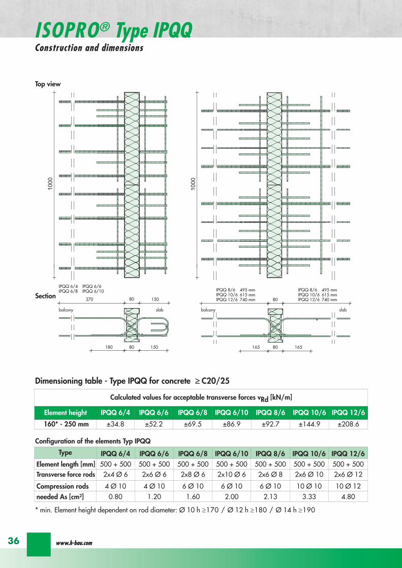
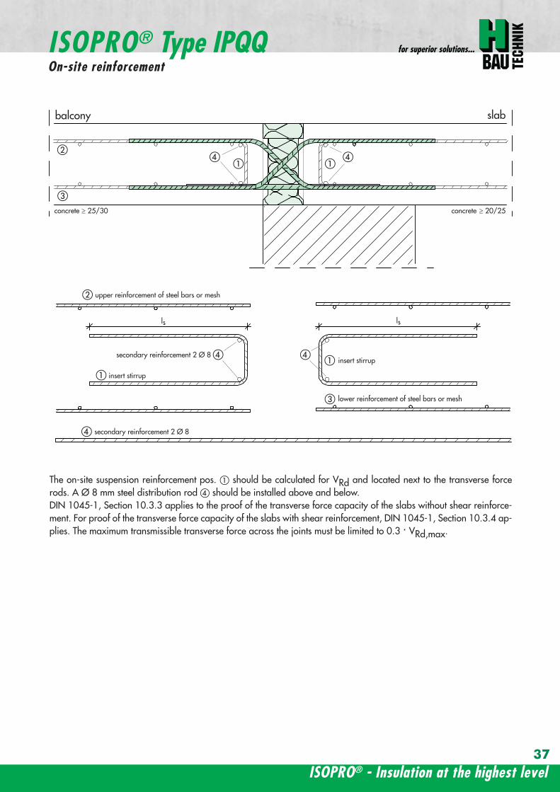
ISOPROreg - Insulation at the highest level
for superior solutions
37
ISOPROreg Type IPQQOn-site reinforcement
balcony slab
upper reinforcement of steel bars or mesh
lower reinforcement of steel bars or mesh
ls ls
b
c
a
c
d
b
insert stirrupa
d
dinsert stirrupa
ad
d
secondary reinforcement 2 Oslash 8
concrete concrete
secondary reinforcement 2 Oslash 8
The on-site suspension reinforcement pos should be calculated for VRd and located next to the transverse forcerods A Oslash 8 mm steel distribution rod should be installed above and below DIN 1045-1 Section 1033 applies to the proof of the transverse force capacity of the slabs without shear reinforce-ment For proof of the transverse force capacity of the slabs with shear reinforcement DIN 1045-1 Section 1034 ap-plies The maximum transmissible transverse force across the joints must be limited to 03 VRdmax
wwwh-baucom38
ISOPROreg Type IPQQS 2Construction and dimensions
balcony slab
balcony slab
Calculated values for acceptable transverse forces VRd [kN]
Element height IPQQS 62 IPQQS 82 IPQQS 102 IPQQS 122 IPQQS 142
160 - 250 mm plusmn174 plusmn309 plusmn483 plusmn695 plusmn947
Dimensioning table - Type IPQQS2 for concrete gege C2025
Type IPQQS 62 IPQQS 82 IPQQS 102 IPQQS 122 IPQQS 142
Element length [mm] 300 300 300 300 300
Transverse force rods 2x 2 Oslash 6 2x 2 Oslash 8 2x 2 Oslash 10 2x 2 Oslash 12 2x 2 Oslash 14
Compression rods 2 Oslash 10 2 Oslash 10 3 Oslash 10 4 Oslash 12 4 Oslash 14needed As [cmsup2] 040 071 111 160 218
Configuration of the elements Type IPQQS2
IPQQS 82 495mmIPQQS 102 615mmIPQQS 122 740mmIPQQS 142 860mm
IPQQS 62
IPQQS 82 495mmIPQQS 102 615mmIPQQS 122 740mmIPQQS 142 860mm
min Element height dependent on rod diameter Oslash 10 h ge170 Oslash 12 h ge180 Oslash 14 h ge190
ISOPROreg - Insulation at the highest level
for superior solutions
39
ISOPROreg Type IPQQS 3Construction and dimensions
balcony slab
balcony slab
Calculated values for acceptable transverse forces VRd [kN]
Element height IPQQS 63 IPQQS 83 IPQQS 103 IPQQS 123 IPQQS 143
160 - 250 mm plusmn261 plusmn464 plusmn724 plusmn1043 plusmn1420
Dimensioning table - Type IPQQS3 for concrete gege C2025
Type IPQQS 63 IPQQS 83 IPQQS 103 IPQQS 123 IPQQS 143
Element length [mm] 400 400 400 400 400
Transverse force rods 2x 3 Oslash 6 2x 3 Oslash 8 2x 3 Oslash 10 2x 3 Oslash 12 2x 3 Oslash 14
Compression rods 2 Oslash 10 3 Oslash 10 4 Oslash 12 5 Oslash 12 6 Oslash 14needed As [cmsup2] 060 107 167 240 327
Configuration of the elements Type IPQQS3
min Element height dependent on rod diameter Oslash 10 h ge170 Oslash 12 h ge180 Oslash 14 h ge190 alternatively in Element length 500 mm available
IPQQS 83 495mmIPQQS 103 615mmIPQQS 123 740mmIPQQS 143 860mm
IPQQS 63
IPQQS 83 495mmIPQQS 103 615mmIPQQS 123 740mmIPQQS 143 860mm
wwwh-baucom40
ISOPROreg Type IPTDConstruction and dimensions
IPTD IPTD
inset balcony
30
balcony slab
Top view
Section
Example
Table of Dimensions ndash Type IPTD [length in mm]
TypeTension rod Transverse force rod Compression rod Supplemental transverse force
ZL QL DL Q10L Q12LIPTD 126 820 497 820 617 742IPTD 127 820 497 820 617 742IPTD 1210 820 497 820 617 742IPTD 1212 820 497 820 617 742IPTD 1410 960 497 960 617 742
ISOPROreg - Insulation at the highest level
for superior solutions
41
ISOPROreg Type IPTDOn-site reinforcement
balcony slab
upper reinforcement of steelbars or mesh
lower reinforcement of steelbars or mesh
secondary reinforcement 2 Oslash 8
secondary reinforcement 2 Oslash 8
insert stirrup
ls ls
AA
a
b
c
d
d
a
c
d
b
lower reinforcement of steelbars or meshc
upper reinforcement of steelbars or meshb
d
insert stirrupee
b
c
a
a
Section A - A
ISOPRO transverse force rods ISOPRO compression rods
ISOPRO transverse force rods ISOPRO tension rods
d
concrete concrete
The on-site suspension reinforcement pos should be calculated for VRd and located next to the transverse forcerods A Oslash 8 mm steel distribution rod should be installed above and below DIN 1045-1 Section 1033 applies to the proof of the transverse force capacity of the slabs without shear reinforce-ment For proof of the transverse force capacity of the slabs with shear reinforcement DIN 1045-1 Section 1034 ap-plies The maximum transmissible transverse force across the joints must be limited to 03 VRdmax
wwwh-baucom42
ISOPROreg Type IPTDDimensioning table for concrete gege C2025
Plate thickness [mm] withreference to cv [mm] Rated values for moment loading mRd [kNmm]
30 35 IPTD 126IPTD 126
Q10IPTD 126
Q12IPTD 127
IPTD 127Q10
IPTD 127Q12
IPTD 1210
- 160 plusmn 145 - - plusmn 182 - - plusmn 253160 - plusmn 154 - - plusmn 193 - - plusmn 269- 170 plusmn 162 plusmn 146 - plusmn 204 plusmn 187 - plusmn 284
170 - plusmn 171 plusmn 154 - plusmn 214 plusmn 197 - plusmn 299- 180 plusmn 180 plusmn 162 plusmn 145 plusmn 225 plusmn 208 plusmn 190 plusmn 314
180 - plusmn 189 plusmn 170 plusmn 152 plusmn 236 plusmn 218 plusmn 199 plusmn 330- 190 plusmn 197 plusmn 178 plusmn 159 plusmn 247 plusmn 228 plusmn 209 plusmn 345
190 - plusmn 206 plusmn 186 plusmn 166 plusmn 258 plusmn 238 plusmn 218 plusmn 360- 200 plusmn 215 plusmn 194 plusmn 173 plusmn 269 plusmn 248 plusmn 227 plusmn 375
200 - plusmn 223 plusmn 202 plusmn 180 plusmn 280 plusmn 258 plusmn 236 plusmn 391- 210 plusmn 232 plusmn 209 plusmn 187 plusmn 291 plusmn 268 plusmn 246 plusmn 406
210 - plusmn 241 plusmn 217 plusmn 194 plusmn 302 plusmn 278 plusmn 255 plusmn 421- 220 plusmn 250 plusmn 225 plusmn 201 plusmn 313 plusmn 288 plusmn 264 plusmn 437
220 - plusmn 258 plusmn 233 plusmn 208 plusmn 324 plusmn 298 plusmn 273 plusmn 452- 230 plusmn 267 plusmn 241 plusmn 215 plusmn 335 plusmn 308 plusmn 283 plusmn 467
230 - plusmn 276 plusmn 249 plusmn 222 plusmn 346 plusmn 318 plusmn 292 plusmn 482- 240 plusmn 285 plusmn 257 plusmn 229 plusmn 357 plusmn 328 plusmn 301 plusmn 498
240 - plusmn 293 plusmn 265 plusmn 236 plusmn 368 plusmn 339 plusmn 310 plusmn 513- 250 plusmn 302 plusmn 272 plusmn 243 plusmn 379 plusmn 349 plusmn 320 plusmn 528
250 - plusmn 311 plusmn 280 plusmn 250 plusmn 390 plusmn 359 plusmn 329 plusmn 543
Rated values for transverse force loading vRd [kNm]
h = 160 - 250 [mm ] plusmn 415 plusmn 762 plusmn 1098 plusmn 415 plusmn 762 plusmn 1098 plusmn 415
Type IPTD 126 IPTD 126Q10
IPTD 126Q12
IPTD 127 IPTD 127Q10
IPTD 127Q12
IPTD 1210
Element lenght [mm] 500 + 500 500 + 500 500 + 500 500 + 500 500 + 500 500 + 500 500 + 500
Tension rods 6 Oslash 12 6 Oslash 12 6 Oslash 122 Oslash 10 + 6 Oslash 12
2 Oslash 10 + 6 Oslash 12
2 Oslash 10 +6 Oslash 12
10 Oslash 12
Transverse forcerods
2x4 Oslash 8 2x4 Oslash 10 2x4 Oslash 12 2x4 Oslash 8 2x4 Oslash 10 2x4 Oslash 12 2x4 Oslash 8
Compression rods 6 Oslash 12 6 Oslash 12 6 Oslash 122 Oslash 10 + 6 Oslash 12
2 Oslash 10 +6 Oslash 12
2 Oslash 10 +6 Oslash 12
10 Oslash 12
Configuration of the elements Type IPTD
ISOPROreg - Insulation at the highest level
for superior solutions
43
ISOPROreg Type IPTDDimensioning table for concrete gege C2025
Rated values for moment loading mRd [kNmm]
IPTD 1210Q10
IPTD 1210Q12
IPTD 1212IPTD 1212
Q10IPTD 1212
Q12IPTD 1410
IPTD 1410Q10
IPTD 1410Q12
- - plusmn 307 - - plusmn 349 - -- - plusmn 326 - - plusmn 371 - -
plusmn 268 - plusmn 345 plusmn 328 - plusmn 392 plusmn 377 -plusmn 282 - plusmn 363 plusmn 346 - plusmn 414 plusmn 397 -plusmn 297 plusmn 279 plusmn 382 plusmn 364 plusmn 346 plusmn 436 plusmn 418 plusmn 401plusmn 311 plusmn 293 plusmn 400 plusmn 381 plusmn 363 plusmn- 457 plusmn 439 plusmn 421plusmn 325 plusmn 306 plusmn 419 plusmn 399 plusmn 380 plusmn 479 plusmn 459 plusmn 441plusmn 340 plusmn 320 plusmn 437 plusmn 417 plusmn 397 plusmn 500 plusmn 480 plusmn 461plusmn 354 plusmn 333 plusmn 456 plusmn 434 plusmn 414 plusmn 522 plusmn 501 plusmn 480plusmn 369 plusmn 347 plusmn 474 plusmn 452 plusmn 430 plusmn 543 plusmn 522 plusmn 500plusmn 383 plusmn 361 plusmn 493 plusmn 470 plusmn 447 plusmn 565 plusmn 542 plusmn 520plusmn 397 plusmn 374 plusmn 511 plusmn 487 plusmn 464 plusmn 587 plusmn 563 plusmn 540plusmn 412 plusmn 388 plusmn 530 plusmn 505 plusmn 481 plusmn 608 plusmn 584 plusmn 560plusmn 426 plusmn 401 plusmn 548 plusmn 523 plusmn 498 plusmn 630 plusmn 604 plusmn 580plusmn 440 plusmn 415 plusmn 567 plusmn 540 plusmn 515 plusmn 351 plusmn 625 plusmn 600plusmn 455 plusmn 428 plusmn 585 plusmn 558 plusmn 531 plusmn 673 plusmn 646 plusmn 619plusmn 469 plusmn 442 plusmn 604 plusmn 576 plusmn 548 plusmn 694 plusmn 666 plusmn 639plusmn 484 plusmn 455 plusmn 622 plusmn 593 plusmn 565 plusmn 716 plusmn 687 plusmn 659plusmn 498 plusmn 469 plusmn 641 plusmn 611 plusmn 582 plusmn 737 plusmn 708 plusmn 679plusmn 512 plusmn 483 plusmn 659 plusmn 629 plusmn 599 plusmn 759 plusmn 728 plusmn 699
Rated values for transverse force loading vRd [kNm]
plusmn 762 plusmn 1098 plusmn 415 plusmn 762 plusmn 1098 plusmn 415 plusmn 762 plusmn 1098
IPTD 1210Q10
IPTD 1210Q12
IPTD 1212 IPTD 1212Q10
IPTD 1212Q12
IPTD 1410 IPTD 1410Q10
IPTD 1410Q12
500 + 500 500 + 500 500 + 500 500 + 500 500 + 500 500 + 500 500 + 500 500 + 500
10 Oslash 12 10 Oslash 12 12 Oslash 12 12 Oslash 12 12 Oslash 12 10 Oslash 14 10 Oslash 14 10 Oslash 14
2x4 Oslash 10 2x4 Oslash 12 2x4 Oslash 8 2x4 Oslash 10 2x4 Oslash 12 2x4 Oslash 8 2x4 Oslash 10 2x4 Oslash 12
10 Oslash 12 10 Oslash 12 12 Oslash 12 12 Oslash 12 12 Oslash 12 10 Oslash 14 10 Oslash 14 10 Oslash 14
wwwh-baucom44
ISOPROreg Type IPQZConstruction and dimensions
300
40
0
300
40
0
balcony slab
balcony slab
For restraint-free support with an IPQZ element it should be opposed by an IPQS element Both elements should bereinforced by a tieback which corresponds in diameter and rod count to the IPQS and IPQZAn on-site stirrup reinforcement is required to connect IPQS to the floor
Calculated values for acceptable transverse forces VRd [kN]
Element height IPQZ 62 IPQZ 82 IPQZ 102 IPQZ 122 IPQZ 142
160 - 250 mm 174 309 483 695 947
IPQZ 63 IPQZ 83 IPQZ 103 IPQZ 123 IPQZ 143
160 - 250 mm 261 464 724 1043 1420
Dimensioning table ndash Type IPQZ for concrete ge C2025
Type IPQZ 62 IPQZ 82 IPQZ 102 IPQZ 122 IPQZ 142Element lenght [mm] 300 300 300 300 300
Transverse force rods 2 Oslash 6 2 Oslash 8 2 Oslash 10 2 Oslash 12 2 Oslash 14
Configuration of the elements
Type IPQZ 63 IPQZ 83 IPQZ 103 IPQZ 123 IPQZ 143Element length [mm] 400 400 400 400 400
Transverse force rods 3 Oslash 6 3 Oslash 8 3 Oslash 10 3 Oslash 12 3 Oslash 14
min Element height dependent on rod diameter Oslash 10 h ge170 Oslash 12 h ge180 Oslash 14 h ge190
IPQZ 82 83 495mmIPQZ102 103 615mmIPQZ122 123 740mmIPQZ 142 143 860mm
IPQZ 82 83 495mmIPQZ102 103 615mmIPQZ122 123 740mmIPQZ 142 143 860mm
IPQZ 62 63
ISOPROreg - Insulation at the highest level
for superior solutions
45
ISOPROreg Type IPQZOn-site reinforcement
Type Tieback Insert stirrup for use with
IPQZ 62 2 Oslash 6 1 Oslash 6 IPQS 62
IPQZ 82 2 Oslash 8 1 Oslash 8 IPQS 82
IPQZ 102 2 Oslash 10 1 Oslash 10 IPQS 102
IPQZ 122 2 Oslash 12 2 Oslash 8 IPQS 122
IPQZ 142 2 Oslash 14 2 Oslash 10 IPQS 142
tie roda
b
stirrup for anchering tie rodb
a
slab slabbalcony
Typ IPQZ Typ IPQS
Type Tieback Insert stirrup for use with
IPQZ 63 3 Oslash 6 2 Oslash 6 IPQS 63
IPQZ 83 3 Oslash 8 2 Oslash 8 IPQS 83
IPQZ 103 3 Oslash 10 2 Oslash 10 IPQS 103
IPQZ 123 3 Oslash 12 3 Oslash 8 IPQS 123
IPQZ 143 3 Oslash 14 3 Oslash 10 IPQS 143
wwwh-baucom46
ISOPROreg Type IPHConstruction and dimensions
The ISOPROreg elements type IPH which absorb horizontal forces must only be used with ISOPROreg cantilever slabs ortransverse force connections
The number of IPH elements to be used is defined by the structural engineer whereby the expansion joint spacing mustbe maintained
When using ISOPROreg IPH elements the force absorption of the line connection must be reduced by the ratio of thelength of the IPH elements to the total connection length as a percentage
independent of cvReinforcement Length of
element
HRd
Transverse force Horizontal Transverse force Horizontal
IPH 1 2 x 1 Oslash 8 - 100 mm plusmn 74 kN -IPH 2 - 1 Oslash 10 100 mm - plusmn181 kNIPH 3 2 x 1 Oslash 8 1 Oslash 10 100 mm plusmn 74 kN plusmn 181 kN
Dimensioning table ndash Type IPH for concrete gege C2025
balcony slab
balcony slab
balcony slab
balcony slab
balcony slab
balcony slab
100
100
100
250 80 250
250 80 250
250 80 250IPH 1 for absorption of horizontal forces parallel to the insulation joint
IPH 2 for absorption of horizontal forces perpendicular to the insulation joint
IPH 3 for absorption of horizontal forces parallel and perpendicular to the insulation joint
ISOPROreg - Insulation at the highest level
for superior solutions
47
ISOPROreg Type IPHOn-site reinforcement
The installation of the ISOPROreg IPH elements is analogous to the installation of the ISOPROreg cantilever slabs or trans-verse force connectionsThe number and positions of the elements are defined in the structural detail The elements must be fixed in their posi-tions
plate slab balcony slab
ls ls
lower reinforcement of steel bars or mesh
d
lower reinforcement of steel bars or mesh
upper reinforcement of steel bars or mesh
a
aa
dc
d
insert stirrup
a
b
c
secondary reinforcement Oslash 8
b
c c
insert stirrup
wwwh-baucom48
ISOPROreg Type IPAConstruction and calculation values
29
0204
0608
1012
1416
1820
2422
2628
0204
0608
1012
1416
1820
2224
2628
0 +10 +20 +30 +40 +50-10-20-30-40-50
dimensioning axis
MEd
VEd
NEd
380
60
gt160
sup3 16
0
130
Section
Mathematical model ndash Static system Interaction diagram
NRd [kN]
M Rd[kNm]
DimensionsLength of element 350 mmFascia thickness 160 ndash 240 mmHeight of element from 160 mmThickness of insulation element 60 mm
ReinforcementTension rods 3 Oslash 8Compression rods 3 Oslash 8Transverse force rods 2 x 2 Oslash 6
Calculated values for NRd = 0MRd 29 kNmelementVRd plusmn 127 kNelement
ISOPROreg - Insulation at the highest level
for superior solutions
49
ISOPROreg Type IPAOn-site reinforcement and installation instructions
400
100
aa
bc
b c
dd
e
f
gh
h
e
g
h
f
inse
rt s
tirru
ps
conn
ectio
n re
info
rcem
ent
conn
ectio
n re
info
rcem
ent
steel bar Oslash 8
upper slab reinforcement
insert stirrups 3 Oslash 8 150 mmsupplied
insert stirrup as constructive edging
lower slab reinforcement
34
160
56 59 60 60 59 56
34
Section Plan
Installation instructions1 Lay lower reinforcement including edging
2 Install ISOPROreg elements type IPA Spacing in accordance with static requirements
3 Install positions and and tie together
4 Lay upper floor reinforcement and tie together with the ISOPROreg reinforcement element
5 Concrete the floor slab Ensure safe positioning
6 Attach the on-site insulation between the ISOPROreg elements
7 Lay the fascia reinforcement and including edging and tie together with the ISOPROreg elements
supplied insulation
Type IPAType IPA
350e = separation of elements
gt 80
gt 16
0
Spacing of the elements Spacing of expansion joints
Expansion joint spacing e le 78 mAbove corner e2 le 35 m
The parapet must be verified as being a continuous supporte = spacing of the elements in accordance with static requirements
wwwh-baucom50
+5 +15 +25 +35-5-15-25-35
05
10
15
0
MEd
NEdVEd
MRdVRd
dimensioning axis
ISOPROreg Type IPFConstruction and calculation values
42034
0
60
100
Section
Mathematical model ndash Static system Interaction diagram
DimensionsLength of element 350 mmHeight of element from 160 mmThickness of insulation element 60 mm
ReinforcementTension rods 3 Oslash 6Compression rods 3 Oslash 6Transverse force rods 2 Oslash 6
Calculated values for NRd = 0MRd plusmn 15 kNmelementVRd + 127 kNelement
NRd [kN]
M Rd[kN
m]
VRd = 127 kN
ISOPROreg - Insulation at the highest level
for superior solutions
51
ISOPROreg Type IPFOn-site reinforcement and installation instructions
b
a insert stirrup min Oslash 6 150 mm
upper slab reinforcement
ac
b
e
d
c lower slab reinforcement
est
eel b
ar Oslash
8
d2
inse
rt s
tirru
p m
in Oslash
6
150
mm
3333
56 59 60 60 59 56
160
350
Section
Plan
Installation instructions1 Lay lower reinforcement including edging
2 Install ISOPROreg elements type IPA Spacing in accordance with static requirements
3 Install positions and and tie together
4 Lay upper floor reinforcement and tie together with the ISOPROreg reinforcement element
5 Concrete the floor slab Ensure safe positioning
6 Attach the on-site insulation between the ISOPROreg elements
7 Lay the fascia reinforcement and including edging and tie together with the ISOPROreg elements
350
60
Type IPF Type IPF
e = separation of elements
supplied insulation
parapet
Spacing of the elements
Spacing of expansion joints
Expansion joint spacing e le 78 mAbove corner e2 le 35 m
The parapet must be verified as beinga continuous support e = spacing of the elements in accor-dance with static requirements
wwwh-baucom52
ISOPROreg Type IPOConstruction and calculation values
23 lK
+PRd
+HEd
lK
sliding film
reinforcedconcrete console
soft-fibre panel
sup3 18
0
sup3 150 60
725
130 60 535
350
sliding film
reinforcedconcrete console
soft-fibre panelsup3
180
sup3 150 60
725
130 60 535
350
Section
Plan Mathematical modelStatic system
DimensionsLength of element 350 mmHeight of element from 180 mmThickness of insulation element 60 mm
ReinforcementTension rods 3 Oslash 6Compression rods 3 Oslash 8Transverse force rods 2 Oslash 10
for Hed = 0 PRd plusmn 171 kNmelement max HRd + 184 kNelement
0 2 4 6 8 10 12 14 16 20 22 Horizontal force HEd [kN]
25
15
10
5
0
P Rd[kN] concrete gege C2530
concrete gege C2025
PRd = 23
PRd = 10
HEd
= 18
4
HEd
= 23
1
ISOPROreg - Insulation at the highest level
for superior solutions
53
ISOPROreg Type IPOOn-site reinforcement and installation instructions
slab
a
a
bde
b
c
c upper reinforcement of steel bars or mesh
lower reinforcement of steel bars or mesh
insert stirrupde
long
itudi
nal r
einf
orce
men
t
clos
ed s
tirru
p
concrete
concrete
Section Installation instructions
1 Lay lower reinforcement including edging
2 Install ISOPROreg elements type IPO Spacingin accordance with static requirements
3 Lay upper floor reinforcement and tie to-gether with the ISOPROreg reinforcement ele-ment
4 Attach the on-site insulation between the ISO-PROreg elements
5 Lay the console reinforcement and andtie together with the ISOPROreg elements Thefloor edge beam must be designed as a con-tinuous support
6 As far as practical the console and the floorshould be concreted simultaneously Ensuresecure positioning
reinforced concrete joist
ISOPRO Type IPO ISOPRO Type IPO
supplied insulation
e = separation of elements350
Spacing of the elements Spacing of expansion joints
Expansion joint spacing e le 78 mAbove corner e2 le 35 m
The parapet must be verified as being a continuous support e = spacing of the elements in accordance with static requirements
wwwh-baucom54
ISOPROreg Type IPSConstruction and calculation values
80
5050
80 ZL
balcony slab plate slab
wall
console
tension rod
transverse force bars
compression strut
ZL
QL
QL
DL
80
DL
100100
BSt 500 Nr Wst Nr 14571
BSt 500 Nr Wst Nr 14571
BSt 500 S
BSt 500 S
Section
80
5050
80 ZL
balcony slab plate slab
wall
console
tension rod
transverse force bars
compression strut
ZL
QL
QL
DL
80
DL
100100
BSt 500 Nr Wst Nr 14571
BSt 500 Nr Wst Nr 14571
BSt 500 S
BSt 500 S
Dimensions - Type IPS [length in mm]
Type Tension rod Transverse forcerod
Compressionrod
ZL QL DLIPS 1 690 500 430IPS 2 820 620 500IPS 3 960 745 570IPS 4 1550 865 600
Dimensioning table for concrete gege C2025Element hight 400 mm IPS 1 IPS 2 IPS 3 IPS 4
moment MRd [kNm] 221 294 375 624
transverse forces VRd [kN] 213 333 480 653
Type IPS 1 IPS 2 IPS 3 IPS 4
Element width [mm] 220 220 220 220
Tension rods 3 Oslash 10 3 Oslash 12 3 Oslash 14 4 Oslash 14
Transverse force rods 2 Oslash 8 2 Oslash 10 2 Oslash 12 2 Oslash 14
Compression rods 3 Oslash 12 3 Oslash 14 3 Oslash 16 3 Oslash 20
Other designs and dimensions are available on requestThe bonding area I underlies the determination of the anchoring lengths However if required the reinforcement rods can also be designed for bonding area II
Configuration of the elements
ISOPROreg - Insulation at the highest level
for superior solutions
55
ISOPROreg Type IPSOn-site reinforcement and installation instructions
wall plate reinforcement to structural calculations
tension rod
transverse force bars
compression strut
a
b
c
d
d
a
b
a closed stirrup
edging
c suspension reinforcementconcrete concrete
Installation instructions
1 Lay wall plate reinforcement to meet structural requirements2 Insert ISOPROreg element type IPS and tie together with the wall
reinforcement Transverse reinforcement in overlap zone in accordance with DIN 1045-1
3 Install and tie together beam reinforcement and according to structural calculations Pos edging in accordance withDIN 1045-1 Pos installed as a closed stirrup to avoid shearing
4 When concreting make sure that both sides are uniformly filled and compacted
5 Formwork offset for the beam in accordance with structural calculations
wall plate reinforcement to structural calculations
tension rod
transverse force bars
compression strut
a
b
c
d
d
a
b
a closed stirrup
edging
c suspension reinforcementconcrete concrete
80
b b
plate slab
Type IPS
wal
l pla
te
Type IPS wal
l pla
te
balcony slab
supplied insulation
Configuration of the elements Expansion joint spacing
TypeJoint spacing [m]
e
IPS 1 113
IPS 2 101
IPS 3 92
IPS 4 80
For corner constructions the maximumrod leg length is e2
wwwh-baucom56
ISOPROreg Type IPWConstruction and calculation values
ZL ZL80
420 420
QL QL
DL DL
290290
low
er s
ectio
n12
50ce
ntre
sec
tion
uppe
r se
ctio
n25
0
h =
150
- 3
50
m
80
balcony
balcony slab
slab
exte
rnal
wal
l
inte
rnal
wal
l
horizontal transverse force bars
horizontal transverse force bars
upper section bht in mm150-250 250 80
lower section bht in mm150-250 1250 80
Section
Table of Dimensions Type IPW [length in mm]
Type
Tension rod Transverseforce rod
Compressionrod
ZL QL DLIPW 1 600 423 270IPW 2 790 563 335IPW 3 980 653 410IPW 4 1170 783 470
Element width b = 150 ndash 250 mmElement height h = 150 ndash 350 mInsulation material thickness t = 80 mm
Dimensioning table for concrete gege C2025Calculated values for acceptable moments MRdy [kNm]
Element height [m] IPW 1 IPW 2 IPW 3 IPW 415 ndash 20 537 918 1169 154420 ndash 25 737 1267 1614 2132
gt 25 937 1616 2059 2720Calculated values for acceptable transverse forces [kN]
vRdz [kN] 412 622 1066 1535vRdy [kN] plusmn137 plusmn137 plusmn137 plusmn137
Type IPW 1 IPW 2 IPW 3 IPW 4Element height [m] ge150 ge150 ge150 ge150Tension rods 4 Oslash 6 4 Oslash 8 4 Oslash 10 4 Oslash 12Transverse force rods Qz 6 Oslash 6 6 Oslash 8 6 Oslash 10 6 Oslash 12Transverse force rods Qy 2 x 2 Oslash 6 2 x 2 Oslash 6 2 x 2 Oslash 6 2 x 2 Oslash 6Compression rods 6 Oslash 8 6 Oslash 10 6 Oslash 12 6 Oslash 14
Configuration of the elements
Moment effects from wind loading are absorbed bythe stiffening effect of the balcony slab
MRdz = 0
Bonding area II underlies the determination of theoverlap lengths On request the anchoring lengthscan also be dimensioned for bonding area I Designsand dimensions deviating from the standard ele-ments are available on request
ISOPROreg - Insulation at the highest level
for superior solutions
57
ISOPROreg Type IPWOn-site reinforcement and installation instructions
MRdz
VRdz VRdy
x
z
y
MRdy
Mathematical model ndash Static system
balcony slab
balcony slab
steel
mes
h re
info
rcem
ent
a
steel
mes
h re
info
rcem
ent
b
e connection reinforcementto structural calculations
f
insert stirrupas constructive edging c
c
d steel bar min 2 Oslash 8
concrete sup3 2025
exte
rnal
wal
l
inte
rnal
wal
l
insert stirrupas constructive edging
connection reinforcementto structural calculations
a bc c
d
d
steel bar min 2 Oslash 8
steel bar min 2 Oslash 8
insert stirrupinsert stirrupsteel mesh reinforcement steel mesh reinforcement
80
wall p
late
wall p
late
balcony slab
plate slab
Type IPWsupplied insulation
Type IPW
b b
e e e
Configuration of the elements
Installation instructions
1 Position internal wall reinforcement 2 Attach the constructive edging inter-
nally (insert stirrup)3 Starting at the bottom assemble the in-
dividual ISOPROreg elements type IPWand tie together with the wall reinforce-ment
4 Erect and internally and tie to-gether
5 Position the external wall reinforce-ments and in accordancewith structural design and tie to theISOPROreg elements
6 When concreting pay particular atten-tion to the positional security of the ele-ments It is recommended to fill andcompact both wall plates at the sametime
wwwh-baucom58
ISOPROreg
Approvals and Type testing
Approvals
ISOPRO Type IP Z-157-244ISOPRO Type IPT Z-157-243
Type testing
ISOPRO Type IP Test No 0517ISOPRO Type IPT Test No 0518ISOPRO Type IPQ Test No 0519
ISOPROreg - Insulation at the highest level
for superior solutions
59
ISOPROreg
Tender
___________________________________________________________________________
Scope Application area DIN 276013 Concrete and reinforced concrete Floor constructions
Structural installations__________________________________________________________________________________
ISOPROreg supporting and thermally insulating connection elements
01 supporting the balcony slab using ISOPROreg elements from H-BAU Technik GmbH02 required for installation03 m Type IP cv = mm h = mm04 m Type IPQ cv = mm h = mm05 part Type cv = mm h = mm
Special fabrication according to the following description
06 for thermal separation of the concrete07 for the storey floors pos 08 for the roofing pos 09 for 10 and11 for the balcony slap pos 12 for the loggia slab pos 13 for the cantilever slab pos 14 for the 15 in fire protection construction class F9016 the bonding is made in the reinforcement of pos and pos 17 deliver18 deliver install and bond with the connection reinforcement19 only install and bond with the connection reinforcement delivery provided20 the installation is made in accordance with instructions from
H-BAU Technik GmbHAm Guumlterbahnhof 2079771 Klettgau-ErzingenGermanyTel +49 (0) 77 42 92 15-20Fax +49 (0) 77 42 92 15-90
21 in accordance with the detail and reinforcement drawings no 22 material 23 wages 24 unit price
25 total price
wwwh-baucom60
NOTES
ISOPROreg - Insulation at the highest level
for superior solutions
61
NOTES
wwwh-baucom
Concreting with system
ISOPROreg
KESIIRAPIDOBATreg
JSDHEDFERBOXreg
BOXFERreg
GRIPRIPreg
PENTAFLEXreg
RIPINOXreg
WARMBORDreg
SCHALBORDreg
ZEMBORDreg
SCHALL-ISO ACCESSORIES
H-BAU Technik GmbHAm Guumlterbahnhof 20D-79771 Klettgau-ErzingenTel + 49 (0) 7742 92 15-20Fax + 49 (0) 7742 92 15-90infoklettgauh-baude
Produktion Nord-OstBrandenburger StraszligeD-14641 WachowTel + 49 (0) 3 3239 775-20Fax + 49 (0) 3 3239 775-90infoberlinh-baude
Balcony insulation elementsLifting anchorsShuttering tubesPush-in pegsReinforcement connectorsReinforcement connectorsMasonry connectorsSealing technologyRustproof stainless steelStop end panelsStop end panelsStop end panelsSound insulation elementsSpacers

ISOPROreg - Insulation at the highest level
for superior solutions
39
ISOPROreg Type IPQQS 3Construction and dimensions
balcony slab
balcony slab
Calculated values for acceptable transverse forces VRd [kN]
Element height IPQQS 63 IPQQS 83 IPQQS 103 IPQQS 123 IPQQS 143
160 - 250 mm plusmn261 plusmn464 plusmn724 plusmn1043 plusmn1420
Dimensioning table - Type IPQQS3 for concrete gege C2025
Type IPQQS 63 IPQQS 83 IPQQS 103 IPQQS 123 IPQQS 143
Element length [mm] 400 400 400 400 400
Transverse force rods 2x 3 Oslash 6 2x 3 Oslash 8 2x 3 Oslash 10 2x 3 Oslash 12 2x 3 Oslash 14
Compression rods 2 Oslash 10 3 Oslash 10 4 Oslash 12 5 Oslash 12 6 Oslash 14needed As [cmsup2] 060 107 167 240 327
Configuration of the elements Type IPQQS3
min Element height dependent on rod diameter Oslash 10 h ge170 Oslash 12 h ge180 Oslash 14 h ge190 alternatively in Element length 500 mm available
IPQQS 83 495mmIPQQS 103 615mmIPQQS 123 740mmIPQQS 143 860mm
IPQQS 63
IPQQS 83 495mmIPQQS 103 615mmIPQQS 123 740mmIPQQS 143 860mm
wwwh-baucom40
ISOPROreg Type IPTDConstruction and dimensions
IPTD IPTD
inset balcony
30
balcony slab
Top view
Section
Example
Table of Dimensions ndash Type IPTD [length in mm]
TypeTension rod Transverse force rod Compression rod Supplemental transverse force
ZL QL DL Q10L Q12LIPTD 126 820 497 820 617 742IPTD 127 820 497 820 617 742IPTD 1210 820 497 820 617 742IPTD 1212 820 497 820 617 742IPTD 1410 960 497 960 617 742
ISOPROreg - Insulation at the highest level
for superior solutions
41
ISOPROreg Type IPTDOn-site reinforcement
balcony slab
upper reinforcement of steelbars or mesh
lower reinforcement of steelbars or mesh
secondary reinforcement 2 Oslash 8
secondary reinforcement 2 Oslash 8
insert stirrup
ls ls
AA
a
b
c
d
d
a
c
d
b
lower reinforcement of steelbars or meshc
upper reinforcement of steelbars or meshb
d
insert stirrupee
b
c
a
a
Section A - A
ISOPRO transverse force rods ISOPRO compression rods
ISOPRO transverse force rods ISOPRO tension rods
d
concrete concrete
The on-site suspension reinforcement pos should be calculated for VRd and located next to the transverse forcerods A Oslash 8 mm steel distribution rod should be installed above and below DIN 1045-1 Section 1033 applies to the proof of the transverse force capacity of the slabs without shear reinforce-ment For proof of the transverse force capacity of the slabs with shear reinforcement DIN 1045-1 Section 1034 ap-plies The maximum transmissible transverse force across the joints must be limited to 03 VRdmax
wwwh-baucom42
ISOPROreg Type IPTDDimensioning table for concrete gege C2025
Plate thickness [mm] withreference to cv [mm] Rated values for moment loading mRd [kNmm]
30 35 IPTD 126IPTD 126
Q10IPTD 126
Q12IPTD 127
IPTD 127Q10
IPTD 127Q12
IPTD 1210
- 160 plusmn 145 - - plusmn 182 - - plusmn 253160 - plusmn 154 - - plusmn 193 - - plusmn 269- 170 plusmn 162 plusmn 146 - plusmn 204 plusmn 187 - plusmn 284
170 - plusmn 171 plusmn 154 - plusmn 214 plusmn 197 - plusmn 299- 180 plusmn 180 plusmn 162 plusmn 145 plusmn 225 plusmn 208 plusmn 190 plusmn 314
180 - plusmn 189 plusmn 170 plusmn 152 plusmn 236 plusmn 218 plusmn 199 plusmn 330- 190 plusmn 197 plusmn 178 plusmn 159 plusmn 247 plusmn 228 plusmn 209 plusmn 345
190 - plusmn 206 plusmn 186 plusmn 166 plusmn 258 plusmn 238 plusmn 218 plusmn 360- 200 plusmn 215 plusmn 194 plusmn 173 plusmn 269 plusmn 248 plusmn 227 plusmn 375
200 - plusmn 223 plusmn 202 plusmn 180 plusmn 280 plusmn 258 plusmn 236 plusmn 391- 210 plusmn 232 plusmn 209 plusmn 187 plusmn 291 plusmn 268 plusmn 246 plusmn 406
210 - plusmn 241 plusmn 217 plusmn 194 plusmn 302 plusmn 278 plusmn 255 plusmn 421- 220 plusmn 250 plusmn 225 plusmn 201 plusmn 313 plusmn 288 plusmn 264 plusmn 437
220 - plusmn 258 plusmn 233 plusmn 208 plusmn 324 plusmn 298 plusmn 273 plusmn 452- 230 plusmn 267 plusmn 241 plusmn 215 plusmn 335 plusmn 308 plusmn 283 plusmn 467
230 - plusmn 276 plusmn 249 plusmn 222 plusmn 346 plusmn 318 plusmn 292 plusmn 482- 240 plusmn 285 plusmn 257 plusmn 229 plusmn 357 plusmn 328 plusmn 301 plusmn 498
240 - plusmn 293 plusmn 265 plusmn 236 plusmn 368 plusmn 339 plusmn 310 plusmn 513- 250 plusmn 302 plusmn 272 plusmn 243 plusmn 379 plusmn 349 plusmn 320 plusmn 528
250 - plusmn 311 plusmn 280 plusmn 250 plusmn 390 plusmn 359 plusmn 329 plusmn 543
Rated values for transverse force loading vRd [kNm]
h = 160 - 250 [mm ] plusmn 415 plusmn 762 plusmn 1098 plusmn 415 plusmn 762 plusmn 1098 plusmn 415
Type IPTD 126 IPTD 126Q10
IPTD 126Q12
IPTD 127 IPTD 127Q10
IPTD 127Q12
IPTD 1210
Element lenght [mm] 500 + 500 500 + 500 500 + 500 500 + 500 500 + 500 500 + 500 500 + 500
Tension rods 6 Oslash 12 6 Oslash 12 6 Oslash 122 Oslash 10 + 6 Oslash 12
2 Oslash 10 + 6 Oslash 12
2 Oslash 10 +6 Oslash 12
10 Oslash 12
Transverse forcerods
2x4 Oslash 8 2x4 Oslash 10 2x4 Oslash 12 2x4 Oslash 8 2x4 Oslash 10 2x4 Oslash 12 2x4 Oslash 8
Compression rods 6 Oslash 12 6 Oslash 12 6 Oslash 122 Oslash 10 + 6 Oslash 12
2 Oslash 10 +6 Oslash 12
2 Oslash 10 +6 Oslash 12
10 Oslash 12
Configuration of the elements Type IPTD
ISOPROreg - Insulation at the highest level
for superior solutions
43
ISOPROreg Type IPTDDimensioning table for concrete gege C2025
Rated values for moment loading mRd [kNmm]
IPTD 1210Q10
IPTD 1210Q12
IPTD 1212IPTD 1212
Q10IPTD 1212
Q12IPTD 1410
IPTD 1410Q10
IPTD 1410Q12
- - plusmn 307 - - plusmn 349 - -- - plusmn 326 - - plusmn 371 - -
plusmn 268 - plusmn 345 plusmn 328 - plusmn 392 plusmn 377 -plusmn 282 - plusmn 363 plusmn 346 - plusmn 414 plusmn 397 -plusmn 297 plusmn 279 plusmn 382 plusmn 364 plusmn 346 plusmn 436 plusmn 418 plusmn 401plusmn 311 plusmn 293 plusmn 400 plusmn 381 plusmn 363 plusmn- 457 plusmn 439 plusmn 421plusmn 325 plusmn 306 plusmn 419 plusmn 399 plusmn 380 plusmn 479 plusmn 459 plusmn 441plusmn 340 plusmn 320 plusmn 437 plusmn 417 plusmn 397 plusmn 500 plusmn 480 plusmn 461plusmn 354 plusmn 333 plusmn 456 plusmn 434 plusmn 414 plusmn 522 plusmn 501 plusmn 480plusmn 369 plusmn 347 plusmn 474 plusmn 452 plusmn 430 plusmn 543 plusmn 522 plusmn 500plusmn 383 plusmn 361 plusmn 493 plusmn 470 plusmn 447 plusmn 565 plusmn 542 plusmn 520plusmn 397 plusmn 374 plusmn 511 plusmn 487 plusmn 464 plusmn 587 plusmn 563 plusmn 540plusmn 412 plusmn 388 plusmn 530 plusmn 505 plusmn 481 plusmn 608 plusmn 584 plusmn 560plusmn 426 plusmn 401 plusmn 548 plusmn 523 plusmn 498 plusmn 630 plusmn 604 plusmn 580plusmn 440 plusmn 415 plusmn 567 plusmn 540 plusmn 515 plusmn 351 plusmn 625 plusmn 600plusmn 455 plusmn 428 plusmn 585 plusmn 558 plusmn 531 plusmn 673 plusmn 646 plusmn 619plusmn 469 plusmn 442 plusmn 604 plusmn 576 plusmn 548 plusmn 694 plusmn 666 plusmn 639plusmn 484 plusmn 455 plusmn 622 plusmn 593 plusmn 565 plusmn 716 plusmn 687 plusmn 659plusmn 498 plusmn 469 plusmn 641 plusmn 611 plusmn 582 plusmn 737 plusmn 708 plusmn 679plusmn 512 plusmn 483 plusmn 659 plusmn 629 plusmn 599 plusmn 759 plusmn 728 plusmn 699
Rated values for transverse force loading vRd [kNm]
plusmn 762 plusmn 1098 plusmn 415 plusmn 762 plusmn 1098 plusmn 415 plusmn 762 plusmn 1098
IPTD 1210Q10
IPTD 1210Q12
IPTD 1212 IPTD 1212Q10
IPTD 1212Q12
IPTD 1410 IPTD 1410Q10
IPTD 1410Q12
500 + 500 500 + 500 500 + 500 500 + 500 500 + 500 500 + 500 500 + 500 500 + 500
10 Oslash 12 10 Oslash 12 12 Oslash 12 12 Oslash 12 12 Oslash 12 10 Oslash 14 10 Oslash 14 10 Oslash 14
2x4 Oslash 10 2x4 Oslash 12 2x4 Oslash 8 2x4 Oslash 10 2x4 Oslash 12 2x4 Oslash 8 2x4 Oslash 10 2x4 Oslash 12
10 Oslash 12 10 Oslash 12 12 Oslash 12 12 Oslash 12 12 Oslash 12 10 Oslash 14 10 Oslash 14 10 Oslash 14
wwwh-baucom44
ISOPROreg Type IPQZConstruction and dimensions
300
40
0
300
40
0
balcony slab
balcony slab
For restraint-free support with an IPQZ element it should be opposed by an IPQS element Both elements should bereinforced by a tieback which corresponds in diameter and rod count to the IPQS and IPQZAn on-site stirrup reinforcement is required to connect IPQS to the floor
Calculated values for acceptable transverse forces VRd [kN]
Element height IPQZ 62 IPQZ 82 IPQZ 102 IPQZ 122 IPQZ 142
160 - 250 mm 174 309 483 695 947
IPQZ 63 IPQZ 83 IPQZ 103 IPQZ 123 IPQZ 143
160 - 250 mm 261 464 724 1043 1420
Dimensioning table ndash Type IPQZ for concrete ge C2025
Type IPQZ 62 IPQZ 82 IPQZ 102 IPQZ 122 IPQZ 142Element lenght [mm] 300 300 300 300 300
Transverse force rods 2 Oslash 6 2 Oslash 8 2 Oslash 10 2 Oslash 12 2 Oslash 14
Configuration of the elements
Type IPQZ 63 IPQZ 83 IPQZ 103 IPQZ 123 IPQZ 143Element length [mm] 400 400 400 400 400
Transverse force rods 3 Oslash 6 3 Oslash 8 3 Oslash 10 3 Oslash 12 3 Oslash 14
min Element height dependent on rod diameter Oslash 10 h ge170 Oslash 12 h ge180 Oslash 14 h ge190
IPQZ 82 83 495mmIPQZ102 103 615mmIPQZ122 123 740mmIPQZ 142 143 860mm
IPQZ 82 83 495mmIPQZ102 103 615mmIPQZ122 123 740mmIPQZ 142 143 860mm
IPQZ 62 63
ISOPROreg - Insulation at the highest level
for superior solutions
45
ISOPROreg Type IPQZOn-site reinforcement
Type Tieback Insert stirrup for use with
IPQZ 62 2 Oslash 6 1 Oslash 6 IPQS 62
IPQZ 82 2 Oslash 8 1 Oslash 8 IPQS 82
IPQZ 102 2 Oslash 10 1 Oslash 10 IPQS 102
IPQZ 122 2 Oslash 12 2 Oslash 8 IPQS 122
IPQZ 142 2 Oslash 14 2 Oslash 10 IPQS 142
tie roda
b
stirrup for anchering tie rodb
a
slab slabbalcony
Typ IPQZ Typ IPQS
Type Tieback Insert stirrup for use with
IPQZ 63 3 Oslash 6 2 Oslash 6 IPQS 63
IPQZ 83 3 Oslash 8 2 Oslash 8 IPQS 83
IPQZ 103 3 Oslash 10 2 Oslash 10 IPQS 103
IPQZ 123 3 Oslash 12 3 Oslash 8 IPQS 123
IPQZ 143 3 Oslash 14 3 Oslash 10 IPQS 143
wwwh-baucom46
ISOPROreg Type IPHConstruction and dimensions
The ISOPROreg elements type IPH which absorb horizontal forces must only be used with ISOPROreg cantilever slabs ortransverse force connections
The number of IPH elements to be used is defined by the structural engineer whereby the expansion joint spacing mustbe maintained
When using ISOPROreg IPH elements the force absorption of the line connection must be reduced by the ratio of thelength of the IPH elements to the total connection length as a percentage
independent of cvReinforcement Length of
element
HRd
Transverse force Horizontal Transverse force Horizontal
IPH 1 2 x 1 Oslash 8 - 100 mm plusmn 74 kN -IPH 2 - 1 Oslash 10 100 mm - plusmn181 kNIPH 3 2 x 1 Oslash 8 1 Oslash 10 100 mm plusmn 74 kN plusmn 181 kN
Dimensioning table ndash Type IPH for concrete gege C2025
balcony slab
balcony slab
balcony slab
balcony slab
balcony slab
balcony slab
100
100
100
250 80 250
250 80 250
250 80 250IPH 1 for absorption of horizontal forces parallel to the insulation joint
IPH 2 for absorption of horizontal forces perpendicular to the insulation joint
IPH 3 for absorption of horizontal forces parallel and perpendicular to the insulation joint
ISOPROreg - Insulation at the highest level
for superior solutions
47
ISOPROreg Type IPHOn-site reinforcement
The installation of the ISOPROreg IPH elements is analogous to the installation of the ISOPROreg cantilever slabs or trans-verse force connectionsThe number and positions of the elements are defined in the structural detail The elements must be fixed in their posi-tions
plate slab balcony slab
ls ls
lower reinforcement of steel bars or mesh
d
lower reinforcement of steel bars or mesh
upper reinforcement of steel bars or mesh
a
aa
dc
d
insert stirrup
a
b
c
secondary reinforcement Oslash 8
b
c c
insert stirrup
wwwh-baucom48
ISOPROreg Type IPAConstruction and calculation values
29
0204
0608
1012
1416
1820
2422
2628
0204
0608
1012
1416
1820
2224
2628
0 +10 +20 +30 +40 +50-10-20-30-40-50
dimensioning axis
MEd
VEd
NEd
380
60
gt160
sup3 16
0
130
Section
Mathematical model ndash Static system Interaction diagram
NRd [kN]
M Rd[kNm]
DimensionsLength of element 350 mmFascia thickness 160 ndash 240 mmHeight of element from 160 mmThickness of insulation element 60 mm
ReinforcementTension rods 3 Oslash 8Compression rods 3 Oslash 8Transverse force rods 2 x 2 Oslash 6
Calculated values for NRd = 0MRd 29 kNmelementVRd plusmn 127 kNelement
ISOPROreg - Insulation at the highest level
for superior solutions
49
ISOPROreg Type IPAOn-site reinforcement and installation instructions
400
100
aa
bc
b c
dd
e
f
gh
h
e
g
h
f
inse
rt s
tirru
ps
conn
ectio
n re
info
rcem
ent
conn
ectio
n re
info
rcem
ent
steel bar Oslash 8
upper slab reinforcement
insert stirrups 3 Oslash 8 150 mmsupplied
insert stirrup as constructive edging
lower slab reinforcement
34
160
56 59 60 60 59 56
34
Section Plan
Installation instructions1 Lay lower reinforcement including edging
2 Install ISOPROreg elements type IPA Spacing in accordance with static requirements
3 Install positions and and tie together
4 Lay upper floor reinforcement and tie together with the ISOPROreg reinforcement element
5 Concrete the floor slab Ensure safe positioning
6 Attach the on-site insulation between the ISOPROreg elements
7 Lay the fascia reinforcement and including edging and tie together with the ISOPROreg elements
supplied insulation
Type IPAType IPA
350e = separation of elements
gt 80
gt 16
0
Spacing of the elements Spacing of expansion joints
Expansion joint spacing e le 78 mAbove corner e2 le 35 m
The parapet must be verified as being a continuous supporte = spacing of the elements in accordance with static requirements
wwwh-baucom50
+5 +15 +25 +35-5-15-25-35
05
10
15
0
MEd
NEdVEd
MRdVRd
dimensioning axis
ISOPROreg Type IPFConstruction and calculation values
42034
0
60
100
Section
Mathematical model ndash Static system Interaction diagram
DimensionsLength of element 350 mmHeight of element from 160 mmThickness of insulation element 60 mm
ReinforcementTension rods 3 Oslash 6Compression rods 3 Oslash 6Transverse force rods 2 Oslash 6
Calculated values for NRd = 0MRd plusmn 15 kNmelementVRd + 127 kNelement
NRd [kN]
M Rd[kN
m]
VRd = 127 kN
ISOPROreg - Insulation at the highest level
for superior solutions
51
ISOPROreg Type IPFOn-site reinforcement and installation instructions
b
a insert stirrup min Oslash 6 150 mm
upper slab reinforcement
ac
b
e
d
c lower slab reinforcement
est
eel b
ar Oslash
8
d2
inse
rt s
tirru
p m
in Oslash
6
150
mm
3333
56 59 60 60 59 56
160
350
Section
Plan
Installation instructions1 Lay lower reinforcement including edging
2 Install ISOPROreg elements type IPA Spacing in accordance with static requirements
3 Install positions and and tie together
4 Lay upper floor reinforcement and tie together with the ISOPROreg reinforcement element
5 Concrete the floor slab Ensure safe positioning
6 Attach the on-site insulation between the ISOPROreg elements
7 Lay the fascia reinforcement and including edging and tie together with the ISOPROreg elements
350
60
Type IPF Type IPF
e = separation of elements
supplied insulation
parapet
Spacing of the elements
Spacing of expansion joints
Expansion joint spacing e le 78 mAbove corner e2 le 35 m
The parapet must be verified as beinga continuous support e = spacing of the elements in accor-dance with static requirements
wwwh-baucom52
ISOPROreg Type IPOConstruction and calculation values
23 lK
+PRd
+HEd
lK
sliding film
reinforcedconcrete console
soft-fibre panel
sup3 18
0
sup3 150 60
725
130 60 535
350
sliding film
reinforcedconcrete console
soft-fibre panelsup3
180
sup3 150 60
725
130 60 535
350
Section
Plan Mathematical modelStatic system
DimensionsLength of element 350 mmHeight of element from 180 mmThickness of insulation element 60 mm
ReinforcementTension rods 3 Oslash 6Compression rods 3 Oslash 8Transverse force rods 2 Oslash 10
for Hed = 0 PRd plusmn 171 kNmelement max HRd + 184 kNelement
0 2 4 6 8 10 12 14 16 20 22 Horizontal force HEd [kN]
25
15
10
5
0
P Rd[kN] concrete gege C2530
concrete gege C2025
PRd = 23
PRd = 10
HEd
= 18
4
HEd
= 23
1
ISOPROreg - Insulation at the highest level
for superior solutions
53
ISOPROreg Type IPOOn-site reinforcement and installation instructions
slab
a
a
bde
b
c
c upper reinforcement of steel bars or mesh
lower reinforcement of steel bars or mesh
insert stirrupde
long
itudi
nal r
einf
orce
men
t
clos
ed s
tirru
p
concrete
concrete
Section Installation instructions
1 Lay lower reinforcement including edging
2 Install ISOPROreg elements type IPO Spacingin accordance with static requirements
3 Lay upper floor reinforcement and tie to-gether with the ISOPROreg reinforcement ele-ment
4 Attach the on-site insulation between the ISO-PROreg elements
5 Lay the console reinforcement and andtie together with the ISOPROreg elements Thefloor edge beam must be designed as a con-tinuous support
6 As far as practical the console and the floorshould be concreted simultaneously Ensuresecure positioning
reinforced concrete joist
ISOPRO Type IPO ISOPRO Type IPO
supplied insulation
e = separation of elements350
Spacing of the elements Spacing of expansion joints
Expansion joint spacing e le 78 mAbove corner e2 le 35 m
The parapet must be verified as being a continuous support e = spacing of the elements in accordance with static requirements
wwwh-baucom54
ISOPROreg Type IPSConstruction and calculation values
80
5050
80 ZL
balcony slab plate slab
wall
console
tension rod
transverse force bars
compression strut
ZL
QL
QL
DL
80
DL
100100
BSt 500 Nr Wst Nr 14571
BSt 500 Nr Wst Nr 14571
BSt 500 S
BSt 500 S
Section
80
5050
80 ZL
balcony slab plate slab
wall
console
tension rod
transverse force bars
compression strut
ZL
QL
QL
DL
80
DL
100100
BSt 500 Nr Wst Nr 14571
BSt 500 Nr Wst Nr 14571
BSt 500 S
BSt 500 S
Dimensions - Type IPS [length in mm]
Type Tension rod Transverse forcerod
Compressionrod
ZL QL DLIPS 1 690 500 430IPS 2 820 620 500IPS 3 960 745 570IPS 4 1550 865 600
Dimensioning table for concrete gege C2025Element hight 400 mm IPS 1 IPS 2 IPS 3 IPS 4
moment MRd [kNm] 221 294 375 624
transverse forces VRd [kN] 213 333 480 653
Type IPS 1 IPS 2 IPS 3 IPS 4
Element width [mm] 220 220 220 220
Tension rods 3 Oslash 10 3 Oslash 12 3 Oslash 14 4 Oslash 14
Transverse force rods 2 Oslash 8 2 Oslash 10 2 Oslash 12 2 Oslash 14
Compression rods 3 Oslash 12 3 Oslash 14 3 Oslash 16 3 Oslash 20
Other designs and dimensions are available on requestThe bonding area I underlies the determination of the anchoring lengths However if required the reinforcement rods can also be designed for bonding area II
Configuration of the elements
ISOPROreg - Insulation at the highest level
for superior solutions
55
ISOPROreg Type IPSOn-site reinforcement and installation instructions
wall plate reinforcement to structural calculations
tension rod
transverse force bars
compression strut
a
b
c
d
d
a
b
a closed stirrup
edging
c suspension reinforcementconcrete concrete
Installation instructions
1 Lay wall plate reinforcement to meet structural requirements2 Insert ISOPROreg element type IPS and tie together with the wall
reinforcement Transverse reinforcement in overlap zone in accordance with DIN 1045-1
3 Install and tie together beam reinforcement and according to structural calculations Pos edging in accordance withDIN 1045-1 Pos installed as a closed stirrup to avoid shearing
4 When concreting make sure that both sides are uniformly filled and compacted
5 Formwork offset for the beam in accordance with structural calculations
wall plate reinforcement to structural calculations
tension rod
transverse force bars
compression strut
a
b
c
d
d
a
b
a closed stirrup
edging
c suspension reinforcementconcrete concrete
80
b b
plate slab
Type IPS
wal
l pla
te
Type IPS wal
l pla
te
balcony slab
supplied insulation
Configuration of the elements Expansion joint spacing
TypeJoint spacing [m]
e
IPS 1 113
IPS 2 101
IPS 3 92
IPS 4 80
For corner constructions the maximumrod leg length is e2
wwwh-baucom56
ISOPROreg Type IPWConstruction and calculation values
ZL ZL80
420 420
QL QL
DL DL
290290
low
er s
ectio
n12
50ce
ntre
sec
tion
uppe
r se
ctio
n25
0
h =
150
- 3
50
m
80
balcony
balcony slab
slab
exte
rnal
wal
l
inte
rnal
wal
l
horizontal transverse force bars
horizontal transverse force bars
upper section bht in mm150-250 250 80
lower section bht in mm150-250 1250 80
Section
Table of Dimensions Type IPW [length in mm]
Type
Tension rod Transverseforce rod
Compressionrod
ZL QL DLIPW 1 600 423 270IPW 2 790 563 335IPW 3 980 653 410IPW 4 1170 783 470
Element width b = 150 ndash 250 mmElement height h = 150 ndash 350 mInsulation material thickness t = 80 mm
Dimensioning table for concrete gege C2025Calculated values for acceptable moments MRdy [kNm]
Element height [m] IPW 1 IPW 2 IPW 3 IPW 415 ndash 20 537 918 1169 154420 ndash 25 737 1267 1614 2132
gt 25 937 1616 2059 2720Calculated values for acceptable transverse forces [kN]
vRdz [kN] 412 622 1066 1535vRdy [kN] plusmn137 plusmn137 plusmn137 plusmn137
Type IPW 1 IPW 2 IPW 3 IPW 4Element height [m] ge150 ge150 ge150 ge150Tension rods 4 Oslash 6 4 Oslash 8 4 Oslash 10 4 Oslash 12Transverse force rods Qz 6 Oslash 6 6 Oslash 8 6 Oslash 10 6 Oslash 12Transverse force rods Qy 2 x 2 Oslash 6 2 x 2 Oslash 6 2 x 2 Oslash 6 2 x 2 Oslash 6Compression rods 6 Oslash 8 6 Oslash 10 6 Oslash 12 6 Oslash 14
Configuration of the elements
Moment effects from wind loading are absorbed bythe stiffening effect of the balcony slab
MRdz = 0
Bonding area II underlies the determination of theoverlap lengths On request the anchoring lengthscan also be dimensioned for bonding area I Designsand dimensions deviating from the standard ele-ments are available on request
ISOPROreg - Insulation at the highest level
for superior solutions
57
ISOPROreg Type IPWOn-site reinforcement and installation instructions
MRdz
VRdz VRdy
x
z
y
MRdy
Mathematical model ndash Static system
balcony slab
balcony slab
steel
mes
h re
info
rcem
ent
a
steel
mes
h re
info
rcem
ent
b
e connection reinforcementto structural calculations
f
insert stirrupas constructive edging c
c
d steel bar min 2 Oslash 8
concrete sup3 2025
exte
rnal
wal
l
inte
rnal
wal
l
insert stirrupas constructive edging
connection reinforcementto structural calculations
a bc c
d
d
steel bar min 2 Oslash 8
steel bar min 2 Oslash 8
insert stirrupinsert stirrupsteel mesh reinforcement steel mesh reinforcement
80
wall p
late
wall p
late
balcony slab
plate slab
Type IPWsupplied insulation
Type IPW
b b
e e e
Configuration of the elements
Installation instructions
1 Position internal wall reinforcement 2 Attach the constructive edging inter-
nally (insert stirrup)3 Starting at the bottom assemble the in-
dividual ISOPROreg elements type IPWand tie together with the wall reinforce-ment
4 Erect and internally and tie to-gether
5 Position the external wall reinforce-ments and in accordancewith structural design and tie to theISOPROreg elements
6 When concreting pay particular atten-tion to the positional security of the ele-ments It is recommended to fill andcompact both wall plates at the sametime
wwwh-baucom58
ISOPROreg
Approvals and Type testing
Approvals
ISOPRO Type IP Z-157-244ISOPRO Type IPT Z-157-243
Type testing
ISOPRO Type IP Test No 0517ISOPRO Type IPT Test No 0518ISOPRO Type IPQ Test No 0519
ISOPROreg - Insulation at the highest level
for superior solutions
59
ISOPROreg
Tender
___________________________________________________________________________
Scope Application area DIN 276013 Concrete and reinforced concrete Floor constructions
Structural installations__________________________________________________________________________________
ISOPROreg supporting and thermally insulating connection elements
01 supporting the balcony slab using ISOPROreg elements from H-BAU Technik GmbH02 required for installation03 m Type IP cv = mm h = mm04 m Type IPQ cv = mm h = mm05 part Type cv = mm h = mm
Special fabrication according to the following description
06 for thermal separation of the concrete07 for the storey floors pos 08 for the roofing pos 09 for 10 and11 for the balcony slap pos 12 for the loggia slab pos 13 for the cantilever slab pos 14 for the 15 in fire protection construction class F9016 the bonding is made in the reinforcement of pos and pos 17 deliver18 deliver install and bond with the connection reinforcement19 only install and bond with the connection reinforcement delivery provided20 the installation is made in accordance with instructions from
H-BAU Technik GmbHAm Guumlterbahnhof 2079771 Klettgau-ErzingenGermanyTel +49 (0) 77 42 92 15-20Fax +49 (0) 77 42 92 15-90
21 in accordance with the detail and reinforcement drawings no 22 material 23 wages 24 unit price
25 total price
wwwh-baucom60
NOTES
ISOPROreg - Insulation at the highest level
for superior solutions
61
NOTES
wwwh-baucom
Concreting with system
ISOPROreg
KESIIRAPIDOBATreg
JSDHEDFERBOXreg
BOXFERreg
GRIPRIPreg
PENTAFLEXreg
RIPINOXreg
WARMBORDreg
SCHALBORDreg
ZEMBORDreg
SCHALL-ISO ACCESSORIES
H-BAU Technik GmbHAm Guumlterbahnhof 20D-79771 Klettgau-ErzingenTel + 49 (0) 7742 92 15-20Fax + 49 (0) 7742 92 15-90infoklettgauh-baude
Produktion Nord-OstBrandenburger StraszligeD-14641 WachowTel + 49 (0) 3 3239 775-20Fax + 49 (0) 3 3239 775-90infoberlinh-baude
Balcony insulation elementsLifting anchorsShuttering tubesPush-in pegsReinforcement connectorsReinforcement connectorsMasonry connectorsSealing technologyRustproof stainless steelStop end panelsStop end panelsStop end panelsSound insulation elementsSpacers
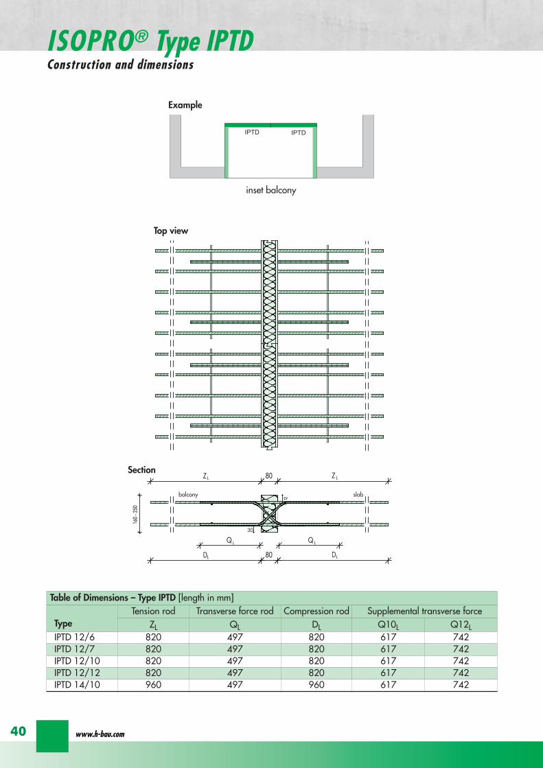

ISOPROreg - Insulation at the highest level
for superior solutions
41
ISOPROreg Type IPTDOn-site reinforcement
balcony slab
upper reinforcement of steelbars or mesh
lower reinforcement of steelbars or mesh
secondary reinforcement 2 Oslash 8
secondary reinforcement 2 Oslash 8
insert stirrup
ls ls
AA
a
b
c
d
d
a
c
d
b
lower reinforcement of steelbars or meshc
upper reinforcement of steelbars or meshb
d
insert stirrupee
b
c
a
a
Section A - A
ISOPRO transverse force rods ISOPRO compression rods
ISOPRO transverse force rods ISOPRO tension rods
d
concrete concrete
The on-site suspension reinforcement pos should be calculated for VRd and located next to the transverse forcerods A Oslash 8 mm steel distribution rod should be installed above and below DIN 1045-1 Section 1033 applies to the proof of the transverse force capacity of the slabs without shear reinforce-ment For proof of the transverse force capacity of the slabs with shear reinforcement DIN 1045-1 Section 1034 ap-plies The maximum transmissible transverse force across the joints must be limited to 03 VRdmax
wwwh-baucom42
ISOPROreg Type IPTDDimensioning table for concrete gege C2025
Plate thickness [mm] withreference to cv [mm] Rated values for moment loading mRd [kNmm]
30 35 IPTD 126IPTD 126
Q10IPTD 126
Q12IPTD 127
IPTD 127Q10
IPTD 127Q12
IPTD 1210
- 160 plusmn 145 - - plusmn 182 - - plusmn 253160 - plusmn 154 - - plusmn 193 - - plusmn 269- 170 plusmn 162 plusmn 146 - plusmn 204 plusmn 187 - plusmn 284
170 - plusmn 171 plusmn 154 - plusmn 214 plusmn 197 - plusmn 299- 180 plusmn 180 plusmn 162 plusmn 145 plusmn 225 plusmn 208 plusmn 190 plusmn 314
180 - plusmn 189 plusmn 170 plusmn 152 plusmn 236 plusmn 218 plusmn 199 plusmn 330- 190 plusmn 197 plusmn 178 plusmn 159 plusmn 247 plusmn 228 plusmn 209 plusmn 345
190 - plusmn 206 plusmn 186 plusmn 166 plusmn 258 plusmn 238 plusmn 218 plusmn 360- 200 plusmn 215 plusmn 194 plusmn 173 plusmn 269 plusmn 248 plusmn 227 plusmn 375
200 - plusmn 223 plusmn 202 plusmn 180 plusmn 280 plusmn 258 plusmn 236 plusmn 391- 210 plusmn 232 plusmn 209 plusmn 187 plusmn 291 plusmn 268 plusmn 246 plusmn 406
210 - plusmn 241 plusmn 217 plusmn 194 plusmn 302 plusmn 278 plusmn 255 plusmn 421- 220 plusmn 250 plusmn 225 plusmn 201 plusmn 313 plusmn 288 plusmn 264 plusmn 437
220 - plusmn 258 plusmn 233 plusmn 208 plusmn 324 plusmn 298 plusmn 273 plusmn 452- 230 plusmn 267 plusmn 241 plusmn 215 plusmn 335 plusmn 308 plusmn 283 plusmn 467
230 - plusmn 276 plusmn 249 plusmn 222 plusmn 346 plusmn 318 plusmn 292 plusmn 482- 240 plusmn 285 plusmn 257 plusmn 229 plusmn 357 plusmn 328 plusmn 301 plusmn 498
240 - plusmn 293 plusmn 265 plusmn 236 plusmn 368 plusmn 339 plusmn 310 plusmn 513- 250 plusmn 302 plusmn 272 plusmn 243 plusmn 379 plusmn 349 plusmn 320 plusmn 528
250 - plusmn 311 plusmn 280 plusmn 250 plusmn 390 plusmn 359 plusmn 329 plusmn 543
Rated values for transverse force loading vRd [kNm]
h = 160 - 250 [mm ] plusmn 415 plusmn 762 plusmn 1098 plusmn 415 plusmn 762 plusmn 1098 plusmn 415
Type IPTD 126 IPTD 126Q10
IPTD 126Q12
IPTD 127 IPTD 127Q10
IPTD 127Q12
IPTD 1210
Element lenght [mm] 500 + 500 500 + 500 500 + 500 500 + 500 500 + 500 500 + 500 500 + 500
Tension rods 6 Oslash 12 6 Oslash 12 6 Oslash 122 Oslash 10 + 6 Oslash 12
2 Oslash 10 + 6 Oslash 12
2 Oslash 10 +6 Oslash 12
10 Oslash 12
Transverse forcerods
2x4 Oslash 8 2x4 Oslash 10 2x4 Oslash 12 2x4 Oslash 8 2x4 Oslash 10 2x4 Oslash 12 2x4 Oslash 8
Compression rods 6 Oslash 12 6 Oslash 12 6 Oslash 122 Oslash 10 + 6 Oslash 12
2 Oslash 10 +6 Oslash 12
2 Oslash 10 +6 Oslash 12
10 Oslash 12
Configuration of the elements Type IPTD
ISOPROreg - Insulation at the highest level
for superior solutions
43
ISOPROreg Type IPTDDimensioning table for concrete gege C2025
Rated values for moment loading mRd [kNmm]
IPTD 1210Q10
IPTD 1210Q12
IPTD 1212IPTD 1212
Q10IPTD 1212
Q12IPTD 1410
IPTD 1410Q10
IPTD 1410Q12
- - plusmn 307 - - plusmn 349 - -- - plusmn 326 - - plusmn 371 - -
plusmn 268 - plusmn 345 plusmn 328 - plusmn 392 plusmn 377 -plusmn 282 - plusmn 363 plusmn 346 - plusmn 414 plusmn 397 -plusmn 297 plusmn 279 plusmn 382 plusmn 364 plusmn 346 plusmn 436 plusmn 418 plusmn 401plusmn 311 plusmn 293 plusmn 400 plusmn 381 plusmn 363 plusmn- 457 plusmn 439 plusmn 421plusmn 325 plusmn 306 plusmn 419 plusmn 399 plusmn 380 plusmn 479 plusmn 459 plusmn 441plusmn 340 plusmn 320 plusmn 437 plusmn 417 plusmn 397 plusmn 500 plusmn 480 plusmn 461plusmn 354 plusmn 333 plusmn 456 plusmn 434 plusmn 414 plusmn 522 plusmn 501 plusmn 480plusmn 369 plusmn 347 plusmn 474 plusmn 452 plusmn 430 plusmn 543 plusmn 522 plusmn 500plusmn 383 plusmn 361 plusmn 493 plusmn 470 plusmn 447 plusmn 565 plusmn 542 plusmn 520plusmn 397 plusmn 374 plusmn 511 plusmn 487 plusmn 464 plusmn 587 plusmn 563 plusmn 540plusmn 412 plusmn 388 plusmn 530 plusmn 505 plusmn 481 plusmn 608 plusmn 584 plusmn 560plusmn 426 plusmn 401 plusmn 548 plusmn 523 plusmn 498 plusmn 630 plusmn 604 plusmn 580plusmn 440 plusmn 415 plusmn 567 plusmn 540 plusmn 515 plusmn 351 plusmn 625 plusmn 600plusmn 455 plusmn 428 plusmn 585 plusmn 558 plusmn 531 plusmn 673 plusmn 646 plusmn 619plusmn 469 plusmn 442 plusmn 604 plusmn 576 plusmn 548 plusmn 694 plusmn 666 plusmn 639plusmn 484 plusmn 455 plusmn 622 plusmn 593 plusmn 565 plusmn 716 plusmn 687 plusmn 659plusmn 498 plusmn 469 plusmn 641 plusmn 611 plusmn 582 plusmn 737 plusmn 708 plusmn 679plusmn 512 plusmn 483 plusmn 659 plusmn 629 plusmn 599 plusmn 759 plusmn 728 plusmn 699
Rated values for transverse force loading vRd [kNm]
plusmn 762 plusmn 1098 plusmn 415 plusmn 762 plusmn 1098 plusmn 415 plusmn 762 plusmn 1098
IPTD 1210Q10
IPTD 1210Q12
IPTD 1212 IPTD 1212Q10
IPTD 1212Q12
IPTD 1410 IPTD 1410Q10
IPTD 1410Q12
500 + 500 500 + 500 500 + 500 500 + 500 500 + 500 500 + 500 500 + 500 500 + 500
10 Oslash 12 10 Oslash 12 12 Oslash 12 12 Oslash 12 12 Oslash 12 10 Oslash 14 10 Oslash 14 10 Oslash 14
2x4 Oslash 10 2x4 Oslash 12 2x4 Oslash 8 2x4 Oslash 10 2x4 Oslash 12 2x4 Oslash 8 2x4 Oslash 10 2x4 Oslash 12
10 Oslash 12 10 Oslash 12 12 Oslash 12 12 Oslash 12 12 Oslash 12 10 Oslash 14 10 Oslash 14 10 Oslash 14
wwwh-baucom44
ISOPROreg Type IPQZConstruction and dimensions
300
40
0
300
40
0
balcony slab
balcony slab
For restraint-free support with an IPQZ element it should be opposed by an IPQS element Both elements should bereinforced by a tieback which corresponds in diameter and rod count to the IPQS and IPQZAn on-site stirrup reinforcement is required to connect IPQS to the floor
Calculated values for acceptable transverse forces VRd [kN]
Element height IPQZ 62 IPQZ 82 IPQZ 102 IPQZ 122 IPQZ 142
160 - 250 mm 174 309 483 695 947
IPQZ 63 IPQZ 83 IPQZ 103 IPQZ 123 IPQZ 143
160 - 250 mm 261 464 724 1043 1420
Dimensioning table ndash Type IPQZ for concrete ge C2025
Type IPQZ 62 IPQZ 82 IPQZ 102 IPQZ 122 IPQZ 142Element lenght [mm] 300 300 300 300 300
Transverse force rods 2 Oslash 6 2 Oslash 8 2 Oslash 10 2 Oslash 12 2 Oslash 14
Configuration of the elements
Type IPQZ 63 IPQZ 83 IPQZ 103 IPQZ 123 IPQZ 143Element length [mm] 400 400 400 400 400
Transverse force rods 3 Oslash 6 3 Oslash 8 3 Oslash 10 3 Oslash 12 3 Oslash 14
min Element height dependent on rod diameter Oslash 10 h ge170 Oslash 12 h ge180 Oslash 14 h ge190
IPQZ 82 83 495mmIPQZ102 103 615mmIPQZ122 123 740mmIPQZ 142 143 860mm
IPQZ 82 83 495mmIPQZ102 103 615mmIPQZ122 123 740mmIPQZ 142 143 860mm
IPQZ 62 63
ISOPROreg - Insulation at the highest level
for superior solutions
45
ISOPROreg Type IPQZOn-site reinforcement
Type Tieback Insert stirrup for use with
IPQZ 62 2 Oslash 6 1 Oslash 6 IPQS 62
IPQZ 82 2 Oslash 8 1 Oslash 8 IPQS 82
IPQZ 102 2 Oslash 10 1 Oslash 10 IPQS 102
IPQZ 122 2 Oslash 12 2 Oslash 8 IPQS 122
IPQZ 142 2 Oslash 14 2 Oslash 10 IPQS 142
tie roda
b
stirrup for anchering tie rodb
a
slab slabbalcony
Typ IPQZ Typ IPQS
Type Tieback Insert stirrup for use with
IPQZ 63 3 Oslash 6 2 Oslash 6 IPQS 63
IPQZ 83 3 Oslash 8 2 Oslash 8 IPQS 83
IPQZ 103 3 Oslash 10 2 Oslash 10 IPQS 103
IPQZ 123 3 Oslash 12 3 Oslash 8 IPQS 123
IPQZ 143 3 Oslash 14 3 Oslash 10 IPQS 143
wwwh-baucom46
ISOPROreg Type IPHConstruction and dimensions
The ISOPROreg elements type IPH which absorb horizontal forces must only be used with ISOPROreg cantilever slabs ortransverse force connections
The number of IPH elements to be used is defined by the structural engineer whereby the expansion joint spacing mustbe maintained
When using ISOPROreg IPH elements the force absorption of the line connection must be reduced by the ratio of thelength of the IPH elements to the total connection length as a percentage
independent of cvReinforcement Length of
element
HRd
Transverse force Horizontal Transverse force Horizontal
IPH 1 2 x 1 Oslash 8 - 100 mm plusmn 74 kN -IPH 2 - 1 Oslash 10 100 mm - plusmn181 kNIPH 3 2 x 1 Oslash 8 1 Oslash 10 100 mm plusmn 74 kN plusmn 181 kN
Dimensioning table ndash Type IPH for concrete gege C2025
balcony slab
balcony slab
balcony slab
balcony slab
balcony slab
balcony slab
100
100
100
250 80 250
250 80 250
250 80 250IPH 1 for absorption of horizontal forces parallel to the insulation joint
IPH 2 for absorption of horizontal forces perpendicular to the insulation joint
IPH 3 for absorption of horizontal forces parallel and perpendicular to the insulation joint
ISOPROreg - Insulation at the highest level
for superior solutions
47
ISOPROreg Type IPHOn-site reinforcement
The installation of the ISOPROreg IPH elements is analogous to the installation of the ISOPROreg cantilever slabs or trans-verse force connectionsThe number and positions of the elements are defined in the structural detail The elements must be fixed in their posi-tions
plate slab balcony slab
ls ls
lower reinforcement of steel bars or mesh
d
lower reinforcement of steel bars or mesh
upper reinforcement of steel bars or mesh
a
aa
dc
d
insert stirrup
a
b
c
secondary reinforcement Oslash 8
b
c c
insert stirrup
wwwh-baucom48
ISOPROreg Type IPAConstruction and calculation values
29
0204
0608
1012
1416
1820
2422
2628
0204
0608
1012
1416
1820
2224
2628
0 +10 +20 +30 +40 +50-10-20-30-40-50
dimensioning axis
MEd
VEd
NEd
380
60
gt160
sup3 16
0
130
Section
Mathematical model ndash Static system Interaction diagram
NRd [kN]
M Rd[kNm]
DimensionsLength of element 350 mmFascia thickness 160 ndash 240 mmHeight of element from 160 mmThickness of insulation element 60 mm
ReinforcementTension rods 3 Oslash 8Compression rods 3 Oslash 8Transverse force rods 2 x 2 Oslash 6
Calculated values for NRd = 0MRd 29 kNmelementVRd plusmn 127 kNelement
ISOPROreg - Insulation at the highest level
for superior solutions
49
ISOPROreg Type IPAOn-site reinforcement and installation instructions
400
100
aa
bc
b c
dd
e
f
gh
h
e
g
h
f
inse
rt s
tirru
ps
conn
ectio
n re
info
rcem
ent
conn
ectio
n re
info
rcem
ent
steel bar Oslash 8
upper slab reinforcement
insert stirrups 3 Oslash 8 150 mmsupplied
insert stirrup as constructive edging
lower slab reinforcement
34
160
56 59 60 60 59 56
34
Section Plan
Installation instructions1 Lay lower reinforcement including edging
2 Install ISOPROreg elements type IPA Spacing in accordance with static requirements
3 Install positions and and tie together
4 Lay upper floor reinforcement and tie together with the ISOPROreg reinforcement element
5 Concrete the floor slab Ensure safe positioning
6 Attach the on-site insulation between the ISOPROreg elements
7 Lay the fascia reinforcement and including edging and tie together with the ISOPROreg elements
supplied insulation
Type IPAType IPA
350e = separation of elements
gt 80
gt 16
0
Spacing of the elements Spacing of expansion joints
Expansion joint spacing e le 78 mAbove corner e2 le 35 m
The parapet must be verified as being a continuous supporte = spacing of the elements in accordance with static requirements
wwwh-baucom50
+5 +15 +25 +35-5-15-25-35
05
10
15
0
MEd
NEdVEd
MRdVRd
dimensioning axis
ISOPROreg Type IPFConstruction and calculation values
42034
0
60
100
Section
Mathematical model ndash Static system Interaction diagram
DimensionsLength of element 350 mmHeight of element from 160 mmThickness of insulation element 60 mm
ReinforcementTension rods 3 Oslash 6Compression rods 3 Oslash 6Transverse force rods 2 Oslash 6
Calculated values for NRd = 0MRd plusmn 15 kNmelementVRd + 127 kNelement
NRd [kN]
M Rd[kN
m]
VRd = 127 kN
ISOPROreg - Insulation at the highest level
for superior solutions
51
ISOPROreg Type IPFOn-site reinforcement and installation instructions
b
a insert stirrup min Oslash 6 150 mm
upper slab reinforcement
ac
b
e
d
c lower slab reinforcement
est
eel b
ar Oslash
8
d2
inse
rt s
tirru
p m
in Oslash
6
150
mm
3333
56 59 60 60 59 56
160
350
Section
Plan
Installation instructions1 Lay lower reinforcement including edging
2 Install ISOPROreg elements type IPA Spacing in accordance with static requirements
3 Install positions and and tie together
4 Lay upper floor reinforcement and tie together with the ISOPROreg reinforcement element
5 Concrete the floor slab Ensure safe positioning
6 Attach the on-site insulation between the ISOPROreg elements
7 Lay the fascia reinforcement and including edging and tie together with the ISOPROreg elements
350
60
Type IPF Type IPF
e = separation of elements
supplied insulation
parapet
Spacing of the elements
Spacing of expansion joints
Expansion joint spacing e le 78 mAbove corner e2 le 35 m
The parapet must be verified as beinga continuous support e = spacing of the elements in accor-dance with static requirements
wwwh-baucom52
ISOPROreg Type IPOConstruction and calculation values
23 lK
+PRd
+HEd
lK
sliding film
reinforcedconcrete console
soft-fibre panel
sup3 18
0
sup3 150 60
725
130 60 535
350
sliding film
reinforcedconcrete console
soft-fibre panelsup3
180
sup3 150 60
725
130 60 535
350
Section
Plan Mathematical modelStatic system
DimensionsLength of element 350 mmHeight of element from 180 mmThickness of insulation element 60 mm
ReinforcementTension rods 3 Oslash 6Compression rods 3 Oslash 8Transverse force rods 2 Oslash 10
for Hed = 0 PRd plusmn 171 kNmelement max HRd + 184 kNelement
0 2 4 6 8 10 12 14 16 20 22 Horizontal force HEd [kN]
25
15
10
5
0
P Rd[kN] concrete gege C2530
concrete gege C2025
PRd = 23
PRd = 10
HEd
= 18
4
HEd
= 23
1
ISOPROreg - Insulation at the highest level
for superior solutions
53
ISOPROreg Type IPOOn-site reinforcement and installation instructions
slab
a
a
bde
b
c
c upper reinforcement of steel bars or mesh
lower reinforcement of steel bars or mesh
insert stirrupde
long
itudi
nal r
einf
orce
men
t
clos
ed s
tirru
p
concrete
concrete
Section Installation instructions
1 Lay lower reinforcement including edging
2 Install ISOPROreg elements type IPO Spacingin accordance with static requirements
3 Lay upper floor reinforcement and tie to-gether with the ISOPROreg reinforcement ele-ment
4 Attach the on-site insulation between the ISO-PROreg elements
5 Lay the console reinforcement and andtie together with the ISOPROreg elements Thefloor edge beam must be designed as a con-tinuous support
6 As far as practical the console and the floorshould be concreted simultaneously Ensuresecure positioning
reinforced concrete joist
ISOPRO Type IPO ISOPRO Type IPO
supplied insulation
e = separation of elements350
Spacing of the elements Spacing of expansion joints
Expansion joint spacing e le 78 mAbove corner e2 le 35 m
The parapet must be verified as being a continuous support e = spacing of the elements in accordance with static requirements
wwwh-baucom54
ISOPROreg Type IPSConstruction and calculation values
80
5050
80 ZL
balcony slab plate slab
wall
console
tension rod
transverse force bars
compression strut
ZL
QL
QL
DL
80
DL
100100
BSt 500 Nr Wst Nr 14571
BSt 500 Nr Wst Nr 14571
BSt 500 S
BSt 500 S
Section
80
5050
80 ZL
balcony slab plate slab
wall
console
tension rod
transverse force bars
compression strut
ZL
QL
QL
DL
80
DL
100100
BSt 500 Nr Wst Nr 14571
BSt 500 Nr Wst Nr 14571
BSt 500 S
BSt 500 S
Dimensions - Type IPS [length in mm]
Type Tension rod Transverse forcerod
Compressionrod
ZL QL DLIPS 1 690 500 430IPS 2 820 620 500IPS 3 960 745 570IPS 4 1550 865 600
Dimensioning table for concrete gege C2025Element hight 400 mm IPS 1 IPS 2 IPS 3 IPS 4
moment MRd [kNm] 221 294 375 624
transverse forces VRd [kN] 213 333 480 653
Type IPS 1 IPS 2 IPS 3 IPS 4
Element width [mm] 220 220 220 220
Tension rods 3 Oslash 10 3 Oslash 12 3 Oslash 14 4 Oslash 14
Transverse force rods 2 Oslash 8 2 Oslash 10 2 Oslash 12 2 Oslash 14
Compression rods 3 Oslash 12 3 Oslash 14 3 Oslash 16 3 Oslash 20
Other designs and dimensions are available on requestThe bonding area I underlies the determination of the anchoring lengths However if required the reinforcement rods can also be designed for bonding area II
Configuration of the elements
ISOPROreg - Insulation at the highest level
for superior solutions
55
ISOPROreg Type IPSOn-site reinforcement and installation instructions
wall plate reinforcement to structural calculations
tension rod
transverse force bars
compression strut
a
b
c
d
d
a
b
a closed stirrup
edging
c suspension reinforcementconcrete concrete
Installation instructions
1 Lay wall plate reinforcement to meet structural requirements2 Insert ISOPROreg element type IPS and tie together with the wall
reinforcement Transverse reinforcement in overlap zone in accordance with DIN 1045-1
3 Install and tie together beam reinforcement and according to structural calculations Pos edging in accordance withDIN 1045-1 Pos installed as a closed stirrup to avoid shearing
4 When concreting make sure that both sides are uniformly filled and compacted
5 Formwork offset for the beam in accordance with structural calculations
wall plate reinforcement to structural calculations
tension rod
transverse force bars
compression strut
a
b
c
d
d
a
b
a closed stirrup
edging
c suspension reinforcementconcrete concrete
80
b b
plate slab
Type IPS
wal
l pla
te
Type IPS wal
l pla
te
balcony slab
supplied insulation
Configuration of the elements Expansion joint spacing
TypeJoint spacing [m]
e
IPS 1 113
IPS 2 101
IPS 3 92
IPS 4 80
For corner constructions the maximumrod leg length is e2
wwwh-baucom56
ISOPROreg Type IPWConstruction and calculation values
ZL ZL80
420 420
QL QL
DL DL
290290
low
er s
ectio
n12
50ce
ntre
sec
tion
uppe
r se
ctio
n25
0
h =
150
- 3
50
m
80
balcony
balcony slab
slab
exte
rnal
wal
l
inte
rnal
wal
l
horizontal transverse force bars
horizontal transverse force bars
upper section bht in mm150-250 250 80
lower section bht in mm150-250 1250 80
Section
Table of Dimensions Type IPW [length in mm]
Type
Tension rod Transverseforce rod
Compressionrod
ZL QL DLIPW 1 600 423 270IPW 2 790 563 335IPW 3 980 653 410IPW 4 1170 783 470
Element width b = 150 ndash 250 mmElement height h = 150 ndash 350 mInsulation material thickness t = 80 mm
Dimensioning table for concrete gege C2025Calculated values for acceptable moments MRdy [kNm]
Element height [m] IPW 1 IPW 2 IPW 3 IPW 415 ndash 20 537 918 1169 154420 ndash 25 737 1267 1614 2132
gt 25 937 1616 2059 2720Calculated values for acceptable transverse forces [kN]
vRdz [kN] 412 622 1066 1535vRdy [kN] plusmn137 plusmn137 plusmn137 plusmn137
Type IPW 1 IPW 2 IPW 3 IPW 4Element height [m] ge150 ge150 ge150 ge150Tension rods 4 Oslash 6 4 Oslash 8 4 Oslash 10 4 Oslash 12Transverse force rods Qz 6 Oslash 6 6 Oslash 8 6 Oslash 10 6 Oslash 12Transverse force rods Qy 2 x 2 Oslash 6 2 x 2 Oslash 6 2 x 2 Oslash 6 2 x 2 Oslash 6Compression rods 6 Oslash 8 6 Oslash 10 6 Oslash 12 6 Oslash 14
Configuration of the elements
Moment effects from wind loading are absorbed bythe stiffening effect of the balcony slab
MRdz = 0
Bonding area II underlies the determination of theoverlap lengths On request the anchoring lengthscan also be dimensioned for bonding area I Designsand dimensions deviating from the standard ele-ments are available on request
ISOPROreg - Insulation at the highest level
for superior solutions
57
ISOPROreg Type IPWOn-site reinforcement and installation instructions
MRdz
VRdz VRdy
x
z
y
MRdy
Mathematical model ndash Static system
balcony slab
balcony slab
steel
mes
h re
info
rcem
ent
a
steel
mes
h re
info
rcem
ent
b
e connection reinforcementto structural calculations
f
insert stirrupas constructive edging c
c
d steel bar min 2 Oslash 8
concrete sup3 2025
exte
rnal
wal
l
inte
rnal
wal
l
insert stirrupas constructive edging
connection reinforcementto structural calculations
a bc c
d
d
steel bar min 2 Oslash 8
steel bar min 2 Oslash 8
insert stirrupinsert stirrupsteel mesh reinforcement steel mesh reinforcement
80
wall p
late
wall p
late
balcony slab
plate slab
Type IPWsupplied insulation
Type IPW
b b
e e e
Configuration of the elements
Installation instructions
1 Position internal wall reinforcement 2 Attach the constructive edging inter-
nally (insert stirrup)3 Starting at the bottom assemble the in-
dividual ISOPROreg elements type IPWand tie together with the wall reinforce-ment
4 Erect and internally and tie to-gether
5 Position the external wall reinforce-ments and in accordancewith structural design and tie to theISOPROreg elements
6 When concreting pay particular atten-tion to the positional security of the ele-ments It is recommended to fill andcompact both wall plates at the sametime
wwwh-baucom58
ISOPROreg
Approvals and Type testing
Approvals
ISOPRO Type IP Z-157-244ISOPRO Type IPT Z-157-243
Type testing
ISOPRO Type IP Test No 0517ISOPRO Type IPT Test No 0518ISOPRO Type IPQ Test No 0519
ISOPROreg - Insulation at the highest level
for superior solutions
59
ISOPROreg
Tender
___________________________________________________________________________
Scope Application area DIN 276013 Concrete and reinforced concrete Floor constructions
Structural installations__________________________________________________________________________________
ISOPROreg supporting and thermally insulating connection elements
01 supporting the balcony slab using ISOPROreg elements from H-BAU Technik GmbH02 required for installation03 m Type IP cv = mm h = mm04 m Type IPQ cv = mm h = mm05 part Type cv = mm h = mm
Special fabrication according to the following description
06 for thermal separation of the concrete07 for the storey floors pos 08 for the roofing pos 09 for 10 and11 for the balcony slap pos 12 for the loggia slab pos 13 for the cantilever slab pos 14 for the 15 in fire protection construction class F9016 the bonding is made in the reinforcement of pos and pos 17 deliver18 deliver install and bond with the connection reinforcement19 only install and bond with the connection reinforcement delivery provided20 the installation is made in accordance with instructions from
H-BAU Technik GmbHAm Guumlterbahnhof 2079771 Klettgau-ErzingenGermanyTel +49 (0) 77 42 92 15-20Fax +49 (0) 77 42 92 15-90
21 in accordance with the detail and reinforcement drawings no 22 material 23 wages 24 unit price
25 total price
wwwh-baucom60
NOTES
ISOPROreg - Insulation at the highest level
for superior solutions
61
NOTES
wwwh-baucom
Concreting with system
ISOPROreg
KESIIRAPIDOBATreg
JSDHEDFERBOXreg
BOXFERreg
GRIPRIPreg
PENTAFLEXreg
RIPINOXreg
WARMBORDreg
SCHALBORDreg
ZEMBORDreg
SCHALL-ISO ACCESSORIES
H-BAU Technik GmbHAm Guumlterbahnhof 20D-79771 Klettgau-ErzingenTel + 49 (0) 7742 92 15-20Fax + 49 (0) 7742 92 15-90infoklettgauh-baude
Produktion Nord-OstBrandenburger StraszligeD-14641 WachowTel + 49 (0) 3 3239 775-20Fax + 49 (0) 3 3239 775-90infoberlinh-baude
Balcony insulation elementsLifting anchorsShuttering tubesPush-in pegsReinforcement connectorsReinforcement connectorsMasonry connectorsSealing technologyRustproof stainless steelStop end panelsStop end panelsStop end panelsSound insulation elementsSpacers

ISOPROreg - Insulation at the highest level
for superior solutions
43
ISOPROreg Type IPTDDimensioning table for concrete gege C2025
Rated values for moment loading mRd [kNmm]
IPTD 1210Q10
IPTD 1210Q12
IPTD 1212IPTD 1212
Q10IPTD 1212
Q12IPTD 1410
IPTD 1410Q10
IPTD 1410Q12
- - plusmn 307 - - plusmn 349 - -- - plusmn 326 - - plusmn 371 - -
plusmn 268 - plusmn 345 plusmn 328 - plusmn 392 plusmn 377 -plusmn 282 - plusmn 363 plusmn 346 - plusmn 414 plusmn 397 -plusmn 297 plusmn 279 plusmn 382 plusmn 364 plusmn 346 plusmn 436 plusmn 418 plusmn 401plusmn 311 plusmn 293 plusmn 400 plusmn 381 plusmn 363 plusmn- 457 plusmn 439 plusmn 421plusmn 325 plusmn 306 plusmn 419 plusmn 399 plusmn 380 plusmn 479 plusmn 459 plusmn 441plusmn 340 plusmn 320 plusmn 437 plusmn 417 plusmn 397 plusmn 500 plusmn 480 plusmn 461plusmn 354 plusmn 333 plusmn 456 plusmn 434 plusmn 414 plusmn 522 plusmn 501 plusmn 480plusmn 369 plusmn 347 plusmn 474 plusmn 452 plusmn 430 plusmn 543 plusmn 522 plusmn 500plusmn 383 plusmn 361 plusmn 493 plusmn 470 plusmn 447 plusmn 565 plusmn 542 plusmn 520plusmn 397 plusmn 374 plusmn 511 plusmn 487 plusmn 464 plusmn 587 plusmn 563 plusmn 540plusmn 412 plusmn 388 plusmn 530 plusmn 505 plusmn 481 plusmn 608 plusmn 584 plusmn 560plusmn 426 plusmn 401 plusmn 548 plusmn 523 plusmn 498 plusmn 630 plusmn 604 plusmn 580plusmn 440 plusmn 415 plusmn 567 plusmn 540 plusmn 515 plusmn 351 plusmn 625 plusmn 600plusmn 455 plusmn 428 plusmn 585 plusmn 558 plusmn 531 plusmn 673 plusmn 646 plusmn 619plusmn 469 plusmn 442 plusmn 604 plusmn 576 plusmn 548 plusmn 694 plusmn 666 plusmn 639plusmn 484 plusmn 455 plusmn 622 plusmn 593 plusmn 565 plusmn 716 plusmn 687 plusmn 659plusmn 498 plusmn 469 plusmn 641 plusmn 611 plusmn 582 plusmn 737 plusmn 708 plusmn 679plusmn 512 plusmn 483 plusmn 659 plusmn 629 plusmn 599 plusmn 759 plusmn 728 plusmn 699
Rated values for transverse force loading vRd [kNm]
plusmn 762 plusmn 1098 plusmn 415 plusmn 762 plusmn 1098 plusmn 415 plusmn 762 plusmn 1098
IPTD 1210Q10
IPTD 1210Q12
IPTD 1212 IPTD 1212Q10
IPTD 1212Q12
IPTD 1410 IPTD 1410Q10
IPTD 1410Q12
500 + 500 500 + 500 500 + 500 500 + 500 500 + 500 500 + 500 500 + 500 500 + 500
10 Oslash 12 10 Oslash 12 12 Oslash 12 12 Oslash 12 12 Oslash 12 10 Oslash 14 10 Oslash 14 10 Oslash 14
2x4 Oslash 10 2x4 Oslash 12 2x4 Oslash 8 2x4 Oslash 10 2x4 Oslash 12 2x4 Oslash 8 2x4 Oslash 10 2x4 Oslash 12
10 Oslash 12 10 Oslash 12 12 Oslash 12 12 Oslash 12 12 Oslash 12 10 Oslash 14 10 Oslash 14 10 Oslash 14
wwwh-baucom44
ISOPROreg Type IPQZConstruction and dimensions
300
40
0
300
40
0
balcony slab
balcony slab
For restraint-free support with an IPQZ element it should be opposed by an IPQS element Both elements should bereinforced by a tieback which corresponds in diameter and rod count to the IPQS and IPQZAn on-site stirrup reinforcement is required to connect IPQS to the floor
Calculated values for acceptable transverse forces VRd [kN]
Element height IPQZ 62 IPQZ 82 IPQZ 102 IPQZ 122 IPQZ 142
160 - 250 mm 174 309 483 695 947
IPQZ 63 IPQZ 83 IPQZ 103 IPQZ 123 IPQZ 143
160 - 250 mm 261 464 724 1043 1420
Dimensioning table ndash Type IPQZ for concrete ge C2025
Type IPQZ 62 IPQZ 82 IPQZ 102 IPQZ 122 IPQZ 142Element lenght [mm] 300 300 300 300 300
Transverse force rods 2 Oslash 6 2 Oslash 8 2 Oslash 10 2 Oslash 12 2 Oslash 14
Configuration of the elements
Type IPQZ 63 IPQZ 83 IPQZ 103 IPQZ 123 IPQZ 143Element length [mm] 400 400 400 400 400
Transverse force rods 3 Oslash 6 3 Oslash 8 3 Oslash 10 3 Oslash 12 3 Oslash 14
min Element height dependent on rod diameter Oslash 10 h ge170 Oslash 12 h ge180 Oslash 14 h ge190
IPQZ 82 83 495mmIPQZ102 103 615mmIPQZ122 123 740mmIPQZ 142 143 860mm
IPQZ 82 83 495mmIPQZ102 103 615mmIPQZ122 123 740mmIPQZ 142 143 860mm
IPQZ 62 63
ISOPROreg - Insulation at the highest level
for superior solutions
45
ISOPROreg Type IPQZOn-site reinforcement
Type Tieback Insert stirrup for use with
IPQZ 62 2 Oslash 6 1 Oslash 6 IPQS 62
IPQZ 82 2 Oslash 8 1 Oslash 8 IPQS 82
IPQZ 102 2 Oslash 10 1 Oslash 10 IPQS 102
IPQZ 122 2 Oslash 12 2 Oslash 8 IPQS 122
IPQZ 142 2 Oslash 14 2 Oslash 10 IPQS 142
tie roda
b
stirrup for anchering tie rodb
a
slab slabbalcony
Typ IPQZ Typ IPQS
Type Tieback Insert stirrup for use with
IPQZ 63 3 Oslash 6 2 Oslash 6 IPQS 63
IPQZ 83 3 Oslash 8 2 Oslash 8 IPQS 83
IPQZ 103 3 Oslash 10 2 Oslash 10 IPQS 103
IPQZ 123 3 Oslash 12 3 Oslash 8 IPQS 123
IPQZ 143 3 Oslash 14 3 Oslash 10 IPQS 143
wwwh-baucom46
ISOPROreg Type IPHConstruction and dimensions
The ISOPROreg elements type IPH which absorb horizontal forces must only be used with ISOPROreg cantilever slabs ortransverse force connections
The number of IPH elements to be used is defined by the structural engineer whereby the expansion joint spacing mustbe maintained
When using ISOPROreg IPH elements the force absorption of the line connection must be reduced by the ratio of thelength of the IPH elements to the total connection length as a percentage
independent of cvReinforcement Length of
element
HRd
Transverse force Horizontal Transverse force Horizontal
IPH 1 2 x 1 Oslash 8 - 100 mm plusmn 74 kN -IPH 2 - 1 Oslash 10 100 mm - plusmn181 kNIPH 3 2 x 1 Oslash 8 1 Oslash 10 100 mm plusmn 74 kN plusmn 181 kN
Dimensioning table ndash Type IPH for concrete gege C2025
balcony slab
balcony slab
balcony slab
balcony slab
balcony slab
balcony slab
100
100
100
250 80 250
250 80 250
250 80 250IPH 1 for absorption of horizontal forces parallel to the insulation joint
IPH 2 for absorption of horizontal forces perpendicular to the insulation joint
IPH 3 for absorption of horizontal forces parallel and perpendicular to the insulation joint
ISOPROreg - Insulation at the highest level
for superior solutions
47
ISOPROreg Type IPHOn-site reinforcement
The installation of the ISOPROreg IPH elements is analogous to the installation of the ISOPROreg cantilever slabs or trans-verse force connectionsThe number and positions of the elements are defined in the structural detail The elements must be fixed in their posi-tions
plate slab balcony slab
ls ls
lower reinforcement of steel bars or mesh
d
lower reinforcement of steel bars or mesh
upper reinforcement of steel bars or mesh
a
aa
dc
d
insert stirrup
a
b
c
secondary reinforcement Oslash 8
b
c c
insert stirrup
wwwh-baucom48
ISOPROreg Type IPAConstruction and calculation values
29
0204
0608
1012
1416
1820
2422
2628
0204
0608
1012
1416
1820
2224
2628
0 +10 +20 +30 +40 +50-10-20-30-40-50
dimensioning axis
MEd
VEd
NEd
380
60
gt160
sup3 16
0
130
Section
Mathematical model ndash Static system Interaction diagram
NRd [kN]
M Rd[kNm]
DimensionsLength of element 350 mmFascia thickness 160 ndash 240 mmHeight of element from 160 mmThickness of insulation element 60 mm
ReinforcementTension rods 3 Oslash 8Compression rods 3 Oslash 8Transverse force rods 2 x 2 Oslash 6
Calculated values for NRd = 0MRd 29 kNmelementVRd plusmn 127 kNelement
ISOPROreg - Insulation at the highest level
for superior solutions
49
ISOPROreg Type IPAOn-site reinforcement and installation instructions
400
100
aa
bc
b c
dd
e
f
gh
h
e
g
h
f
inse
rt s
tirru
ps
conn
ectio
n re
info
rcem
ent
conn
ectio
n re
info
rcem
ent
steel bar Oslash 8
upper slab reinforcement
insert stirrups 3 Oslash 8 150 mmsupplied
insert stirrup as constructive edging
lower slab reinforcement
34
160
56 59 60 60 59 56
34
Section Plan
Installation instructions1 Lay lower reinforcement including edging
2 Install ISOPROreg elements type IPA Spacing in accordance with static requirements
3 Install positions and and tie together
4 Lay upper floor reinforcement and tie together with the ISOPROreg reinforcement element
5 Concrete the floor slab Ensure safe positioning
6 Attach the on-site insulation between the ISOPROreg elements
7 Lay the fascia reinforcement and including edging and tie together with the ISOPROreg elements
supplied insulation
Type IPAType IPA
350e = separation of elements
gt 80
gt 16
0
Spacing of the elements Spacing of expansion joints
Expansion joint spacing e le 78 mAbove corner e2 le 35 m
The parapet must be verified as being a continuous supporte = spacing of the elements in accordance with static requirements
wwwh-baucom50
+5 +15 +25 +35-5-15-25-35
05
10
15
0
MEd
NEdVEd
MRdVRd
dimensioning axis
ISOPROreg Type IPFConstruction and calculation values
42034
0
60
100
Section
Mathematical model ndash Static system Interaction diagram
DimensionsLength of element 350 mmHeight of element from 160 mmThickness of insulation element 60 mm
ReinforcementTension rods 3 Oslash 6Compression rods 3 Oslash 6Transverse force rods 2 Oslash 6
Calculated values for NRd = 0MRd plusmn 15 kNmelementVRd + 127 kNelement
NRd [kN]
M Rd[kN
m]
VRd = 127 kN
ISOPROreg - Insulation at the highest level
for superior solutions
51
ISOPROreg Type IPFOn-site reinforcement and installation instructions
b
a insert stirrup min Oslash 6 150 mm
upper slab reinforcement
ac
b
e
d
c lower slab reinforcement
est
eel b
ar Oslash
8
d2
inse
rt s
tirru
p m
in Oslash
6
150
mm
3333
56 59 60 60 59 56
160
350
Section
Plan
Installation instructions1 Lay lower reinforcement including edging
2 Install ISOPROreg elements type IPA Spacing in accordance with static requirements
3 Install positions and and tie together
4 Lay upper floor reinforcement and tie together with the ISOPROreg reinforcement element
5 Concrete the floor slab Ensure safe positioning
6 Attach the on-site insulation between the ISOPROreg elements
7 Lay the fascia reinforcement and including edging and tie together with the ISOPROreg elements
350
60
Type IPF Type IPF
e = separation of elements
supplied insulation
parapet
Spacing of the elements
Spacing of expansion joints
Expansion joint spacing e le 78 mAbove corner e2 le 35 m
The parapet must be verified as beinga continuous support e = spacing of the elements in accor-dance with static requirements
wwwh-baucom52
ISOPROreg Type IPOConstruction and calculation values
23 lK
+PRd
+HEd
lK
sliding film
reinforcedconcrete console
soft-fibre panel
sup3 18
0
sup3 150 60
725
130 60 535
350
sliding film
reinforcedconcrete console
soft-fibre panelsup3
180
sup3 150 60
725
130 60 535
350
Section
Plan Mathematical modelStatic system
DimensionsLength of element 350 mmHeight of element from 180 mmThickness of insulation element 60 mm
ReinforcementTension rods 3 Oslash 6Compression rods 3 Oslash 8Transverse force rods 2 Oslash 10
for Hed = 0 PRd plusmn 171 kNmelement max HRd + 184 kNelement
0 2 4 6 8 10 12 14 16 20 22 Horizontal force HEd [kN]
25
15
10
5
0
P Rd[kN] concrete gege C2530
concrete gege C2025
PRd = 23
PRd = 10
HEd
= 18
4
HEd
= 23
1
ISOPROreg - Insulation at the highest level
for superior solutions
53
ISOPROreg Type IPOOn-site reinforcement and installation instructions
slab
a
a
bde
b
c
c upper reinforcement of steel bars or mesh
lower reinforcement of steel bars or mesh
insert stirrupde
long
itudi
nal r
einf
orce
men
t
clos
ed s
tirru
p
concrete
concrete
Section Installation instructions
1 Lay lower reinforcement including edging
2 Install ISOPROreg elements type IPO Spacingin accordance with static requirements
3 Lay upper floor reinforcement and tie to-gether with the ISOPROreg reinforcement ele-ment
4 Attach the on-site insulation between the ISO-PROreg elements
5 Lay the console reinforcement and andtie together with the ISOPROreg elements Thefloor edge beam must be designed as a con-tinuous support
6 As far as practical the console and the floorshould be concreted simultaneously Ensuresecure positioning
reinforced concrete joist
ISOPRO Type IPO ISOPRO Type IPO
supplied insulation
e = separation of elements350
Spacing of the elements Spacing of expansion joints
Expansion joint spacing e le 78 mAbove corner e2 le 35 m
The parapet must be verified as being a continuous support e = spacing of the elements in accordance with static requirements
wwwh-baucom54
ISOPROreg Type IPSConstruction and calculation values
80
5050
80 ZL
balcony slab plate slab
wall
console
tension rod
transverse force bars
compression strut
ZL
QL
QL
DL
80
DL
100100
BSt 500 Nr Wst Nr 14571
BSt 500 Nr Wst Nr 14571
BSt 500 S
BSt 500 S
Section
80
5050
80 ZL
balcony slab plate slab
wall
console
tension rod
transverse force bars
compression strut
ZL
QL
QL
DL
80
DL
100100
BSt 500 Nr Wst Nr 14571
BSt 500 Nr Wst Nr 14571
BSt 500 S
BSt 500 S
Dimensions - Type IPS [length in mm]
Type Tension rod Transverse forcerod
Compressionrod
ZL QL DLIPS 1 690 500 430IPS 2 820 620 500IPS 3 960 745 570IPS 4 1550 865 600
Dimensioning table for concrete gege C2025Element hight 400 mm IPS 1 IPS 2 IPS 3 IPS 4
moment MRd [kNm] 221 294 375 624
transverse forces VRd [kN] 213 333 480 653
Type IPS 1 IPS 2 IPS 3 IPS 4
Element width [mm] 220 220 220 220
Tension rods 3 Oslash 10 3 Oslash 12 3 Oslash 14 4 Oslash 14
Transverse force rods 2 Oslash 8 2 Oslash 10 2 Oslash 12 2 Oslash 14
Compression rods 3 Oslash 12 3 Oslash 14 3 Oslash 16 3 Oslash 20
Other designs and dimensions are available on requestThe bonding area I underlies the determination of the anchoring lengths However if required the reinforcement rods can also be designed for bonding area II
Configuration of the elements
ISOPROreg - Insulation at the highest level
for superior solutions
55
ISOPROreg Type IPSOn-site reinforcement and installation instructions
wall plate reinforcement to structural calculations
tension rod
transverse force bars
compression strut
a
b
c
d
d
a
b
a closed stirrup
edging
c suspension reinforcementconcrete concrete
Installation instructions
1 Lay wall plate reinforcement to meet structural requirements2 Insert ISOPROreg element type IPS and tie together with the wall
reinforcement Transverse reinforcement in overlap zone in accordance with DIN 1045-1
3 Install and tie together beam reinforcement and according to structural calculations Pos edging in accordance withDIN 1045-1 Pos installed as a closed stirrup to avoid shearing
4 When concreting make sure that both sides are uniformly filled and compacted
5 Formwork offset for the beam in accordance with structural calculations
wall plate reinforcement to structural calculations
tension rod
transverse force bars
compression strut
a
b
c
d
d
a
b
a closed stirrup
edging
c suspension reinforcementconcrete concrete
80
b b
plate slab
Type IPS
wal
l pla
te
Type IPS wal
l pla
te
balcony slab
supplied insulation
Configuration of the elements Expansion joint spacing
TypeJoint spacing [m]
e
IPS 1 113
IPS 2 101
IPS 3 92
IPS 4 80
For corner constructions the maximumrod leg length is e2
wwwh-baucom56
ISOPROreg Type IPWConstruction and calculation values
ZL ZL80
420 420
QL QL
DL DL
290290
low
er s
ectio
n12
50ce
ntre
sec
tion
uppe
r se
ctio
n25
0
h =
150
- 3
50
m
80
balcony
balcony slab
slab
exte
rnal
wal
l
inte
rnal
wal
l
horizontal transverse force bars
horizontal transverse force bars
upper section bht in mm150-250 250 80
lower section bht in mm150-250 1250 80
Section
Table of Dimensions Type IPW [length in mm]
Type
Tension rod Transverseforce rod
Compressionrod
ZL QL DLIPW 1 600 423 270IPW 2 790 563 335IPW 3 980 653 410IPW 4 1170 783 470
Element width b = 150 ndash 250 mmElement height h = 150 ndash 350 mInsulation material thickness t = 80 mm
Dimensioning table for concrete gege C2025Calculated values for acceptable moments MRdy [kNm]
Element height [m] IPW 1 IPW 2 IPW 3 IPW 415 ndash 20 537 918 1169 154420 ndash 25 737 1267 1614 2132
gt 25 937 1616 2059 2720Calculated values for acceptable transverse forces [kN]
vRdz [kN] 412 622 1066 1535vRdy [kN] plusmn137 plusmn137 plusmn137 plusmn137
Type IPW 1 IPW 2 IPW 3 IPW 4Element height [m] ge150 ge150 ge150 ge150Tension rods 4 Oslash 6 4 Oslash 8 4 Oslash 10 4 Oslash 12Transverse force rods Qz 6 Oslash 6 6 Oslash 8 6 Oslash 10 6 Oslash 12Transverse force rods Qy 2 x 2 Oslash 6 2 x 2 Oslash 6 2 x 2 Oslash 6 2 x 2 Oslash 6Compression rods 6 Oslash 8 6 Oslash 10 6 Oslash 12 6 Oslash 14
Configuration of the elements
Moment effects from wind loading are absorbed bythe stiffening effect of the balcony slab
MRdz = 0
Bonding area II underlies the determination of theoverlap lengths On request the anchoring lengthscan also be dimensioned for bonding area I Designsand dimensions deviating from the standard ele-ments are available on request
ISOPROreg - Insulation at the highest level
for superior solutions
57
ISOPROreg Type IPWOn-site reinforcement and installation instructions
MRdz
VRdz VRdy
x
z
y
MRdy
Mathematical model ndash Static system
balcony slab
balcony slab
steel
mes
h re
info
rcem
ent
a
steel
mes
h re
info
rcem
ent
b
e connection reinforcementto structural calculations
f
insert stirrupas constructive edging c
c
d steel bar min 2 Oslash 8
concrete sup3 2025
exte
rnal
wal
l
inte
rnal
wal
l
insert stirrupas constructive edging
connection reinforcementto structural calculations
a bc c
d
d
steel bar min 2 Oslash 8
steel bar min 2 Oslash 8
insert stirrupinsert stirrupsteel mesh reinforcement steel mesh reinforcement
80
wall p
late
wall p
late
balcony slab
plate slab
Type IPWsupplied insulation
Type IPW
b b
e e e
Configuration of the elements
Installation instructions
1 Position internal wall reinforcement 2 Attach the constructive edging inter-
nally (insert stirrup)3 Starting at the bottom assemble the in-
dividual ISOPROreg elements type IPWand tie together with the wall reinforce-ment
4 Erect and internally and tie to-gether
5 Position the external wall reinforce-ments and in accordancewith structural design and tie to theISOPROreg elements
6 When concreting pay particular atten-tion to the positional security of the ele-ments It is recommended to fill andcompact both wall plates at the sametime
wwwh-baucom58
ISOPROreg
Approvals and Type testing
Approvals
ISOPRO Type IP Z-157-244ISOPRO Type IPT Z-157-243
Type testing
ISOPRO Type IP Test No 0517ISOPRO Type IPT Test No 0518ISOPRO Type IPQ Test No 0519
ISOPROreg - Insulation at the highest level
for superior solutions
59
ISOPROreg
Tender
___________________________________________________________________________
Scope Application area DIN 276013 Concrete and reinforced concrete Floor constructions
Structural installations__________________________________________________________________________________
ISOPROreg supporting and thermally insulating connection elements
01 supporting the balcony slab using ISOPROreg elements from H-BAU Technik GmbH02 required for installation03 m Type IP cv = mm h = mm04 m Type IPQ cv = mm h = mm05 part Type cv = mm h = mm
Special fabrication according to the following description
06 for thermal separation of the concrete07 for the storey floors pos 08 for the roofing pos 09 for 10 and11 for the balcony slap pos 12 for the loggia slab pos 13 for the cantilever slab pos 14 for the 15 in fire protection construction class F9016 the bonding is made in the reinforcement of pos and pos 17 deliver18 deliver install and bond with the connection reinforcement19 only install and bond with the connection reinforcement delivery provided20 the installation is made in accordance with instructions from
H-BAU Technik GmbHAm Guumlterbahnhof 2079771 Klettgau-ErzingenGermanyTel +49 (0) 77 42 92 15-20Fax +49 (0) 77 42 92 15-90
21 in accordance with the detail and reinforcement drawings no 22 material 23 wages 24 unit price
25 total price
wwwh-baucom60
NOTES
ISOPROreg - Insulation at the highest level
for superior solutions
61
NOTES
wwwh-baucom
Concreting with system
ISOPROreg
KESIIRAPIDOBATreg
JSDHEDFERBOXreg
BOXFERreg
GRIPRIPreg
PENTAFLEXreg
RIPINOXreg
WARMBORDreg
SCHALBORDreg
ZEMBORDreg
SCHALL-ISO ACCESSORIES
H-BAU Technik GmbHAm Guumlterbahnhof 20D-79771 Klettgau-ErzingenTel + 49 (0) 7742 92 15-20Fax + 49 (0) 7742 92 15-90infoklettgauh-baude
Produktion Nord-OstBrandenburger StraszligeD-14641 WachowTel + 49 (0) 3 3239 775-20Fax + 49 (0) 3 3239 775-90infoberlinh-baude
Balcony insulation elementsLifting anchorsShuttering tubesPush-in pegsReinforcement connectorsReinforcement connectorsMasonry connectorsSealing technologyRustproof stainless steelStop end panelsStop end panelsStop end panelsSound insulation elementsSpacers
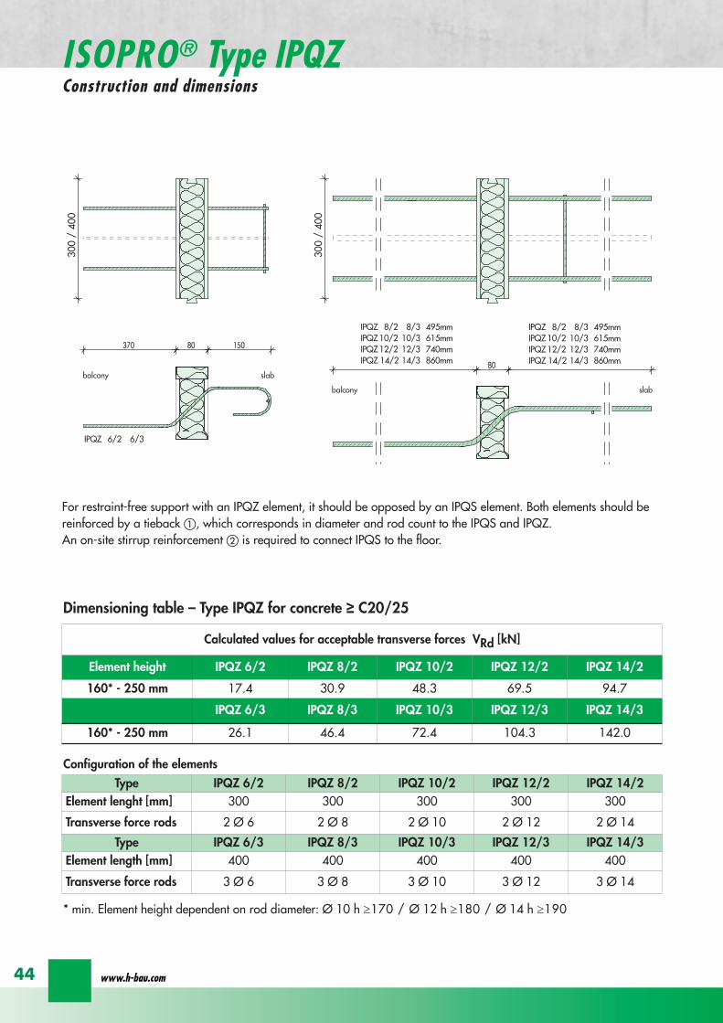
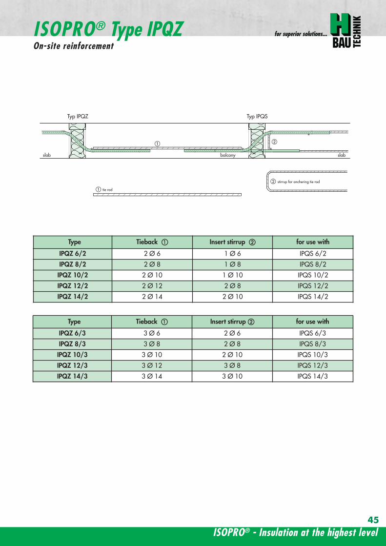
ISOPROreg - Insulation at the highest level
for superior solutions
45
ISOPROreg Type IPQZOn-site reinforcement
Type Tieback Insert stirrup for use with
IPQZ 62 2 Oslash 6 1 Oslash 6 IPQS 62
IPQZ 82 2 Oslash 8 1 Oslash 8 IPQS 82
IPQZ 102 2 Oslash 10 1 Oslash 10 IPQS 102
IPQZ 122 2 Oslash 12 2 Oslash 8 IPQS 122
IPQZ 142 2 Oslash 14 2 Oslash 10 IPQS 142
tie roda
b
stirrup for anchering tie rodb
a
slab slabbalcony
Typ IPQZ Typ IPQS
Type Tieback Insert stirrup for use with
IPQZ 63 3 Oslash 6 2 Oslash 6 IPQS 63
IPQZ 83 3 Oslash 8 2 Oslash 8 IPQS 83
IPQZ 103 3 Oslash 10 2 Oslash 10 IPQS 103
IPQZ 123 3 Oslash 12 3 Oslash 8 IPQS 123
IPQZ 143 3 Oslash 14 3 Oslash 10 IPQS 143
wwwh-baucom46
ISOPROreg Type IPHConstruction and dimensions
The ISOPROreg elements type IPH which absorb horizontal forces must only be used with ISOPROreg cantilever slabs ortransverse force connections
The number of IPH elements to be used is defined by the structural engineer whereby the expansion joint spacing mustbe maintained
When using ISOPROreg IPH elements the force absorption of the line connection must be reduced by the ratio of thelength of the IPH elements to the total connection length as a percentage
independent of cvReinforcement Length of
element
HRd
Transverse force Horizontal Transverse force Horizontal
IPH 1 2 x 1 Oslash 8 - 100 mm plusmn 74 kN -IPH 2 - 1 Oslash 10 100 mm - plusmn181 kNIPH 3 2 x 1 Oslash 8 1 Oslash 10 100 mm plusmn 74 kN plusmn 181 kN
Dimensioning table ndash Type IPH for concrete gege C2025
balcony slab
balcony slab
balcony slab
balcony slab
balcony slab
balcony slab
100
100
100
250 80 250
250 80 250
250 80 250IPH 1 for absorption of horizontal forces parallel to the insulation joint
IPH 2 for absorption of horizontal forces perpendicular to the insulation joint
IPH 3 for absorption of horizontal forces parallel and perpendicular to the insulation joint
ISOPROreg - Insulation at the highest level
for superior solutions
47
ISOPROreg Type IPHOn-site reinforcement
The installation of the ISOPROreg IPH elements is analogous to the installation of the ISOPROreg cantilever slabs or trans-verse force connectionsThe number and positions of the elements are defined in the structural detail The elements must be fixed in their posi-tions
plate slab balcony slab
ls ls
lower reinforcement of steel bars or mesh
d
lower reinforcement of steel bars or mesh
upper reinforcement of steel bars or mesh
a
aa
dc
d
insert stirrup
a
b
c
secondary reinforcement Oslash 8
b
c c
insert stirrup
wwwh-baucom48
ISOPROreg Type IPAConstruction and calculation values
29
0204
0608
1012
1416
1820
2422
2628
0204
0608
1012
1416
1820
2224
2628
0 +10 +20 +30 +40 +50-10-20-30-40-50
dimensioning axis
MEd
VEd
NEd
380
60
gt160
sup3 16
0
130
Section
Mathematical model ndash Static system Interaction diagram
NRd [kN]
M Rd[kNm]
DimensionsLength of element 350 mmFascia thickness 160 ndash 240 mmHeight of element from 160 mmThickness of insulation element 60 mm
ReinforcementTension rods 3 Oslash 8Compression rods 3 Oslash 8Transverse force rods 2 x 2 Oslash 6
Calculated values for NRd = 0MRd 29 kNmelementVRd plusmn 127 kNelement
ISOPROreg - Insulation at the highest level
for superior solutions
49
ISOPROreg Type IPAOn-site reinforcement and installation instructions
400
100
aa
bc
b c
dd
e
f
gh
h
e
g
h
f
inse
rt s
tirru
ps
conn
ectio
n re
info
rcem
ent
conn
ectio
n re
info
rcem
ent
steel bar Oslash 8
upper slab reinforcement
insert stirrups 3 Oslash 8 150 mmsupplied
insert stirrup as constructive edging
lower slab reinforcement
34
160
56 59 60 60 59 56
34
Section Plan
Installation instructions1 Lay lower reinforcement including edging
2 Install ISOPROreg elements type IPA Spacing in accordance with static requirements
3 Install positions and and tie together
4 Lay upper floor reinforcement and tie together with the ISOPROreg reinforcement element
5 Concrete the floor slab Ensure safe positioning
6 Attach the on-site insulation between the ISOPROreg elements
7 Lay the fascia reinforcement and including edging and tie together with the ISOPROreg elements
supplied insulation
Type IPAType IPA
350e = separation of elements
gt 80
gt 16
0
Spacing of the elements Spacing of expansion joints
Expansion joint spacing e le 78 mAbove corner e2 le 35 m
The parapet must be verified as being a continuous supporte = spacing of the elements in accordance with static requirements
wwwh-baucom50
+5 +15 +25 +35-5-15-25-35
05
10
15
0
MEd
NEdVEd
MRdVRd
dimensioning axis
ISOPROreg Type IPFConstruction and calculation values
42034
0
60
100
Section
Mathematical model ndash Static system Interaction diagram
DimensionsLength of element 350 mmHeight of element from 160 mmThickness of insulation element 60 mm
ReinforcementTension rods 3 Oslash 6Compression rods 3 Oslash 6Transverse force rods 2 Oslash 6
Calculated values for NRd = 0MRd plusmn 15 kNmelementVRd + 127 kNelement
NRd [kN]
M Rd[kN
m]
VRd = 127 kN
ISOPROreg - Insulation at the highest level
for superior solutions
51
ISOPROreg Type IPFOn-site reinforcement and installation instructions
b
a insert stirrup min Oslash 6 150 mm
upper slab reinforcement
ac
b
e
d
c lower slab reinforcement
est
eel b
ar Oslash
8
d2
inse
rt s
tirru
p m
in Oslash
6
150
mm
3333
56 59 60 60 59 56
160
350
Section
Plan
Installation instructions1 Lay lower reinforcement including edging
2 Install ISOPROreg elements type IPA Spacing in accordance with static requirements
3 Install positions and and tie together
4 Lay upper floor reinforcement and tie together with the ISOPROreg reinforcement element
5 Concrete the floor slab Ensure safe positioning
6 Attach the on-site insulation between the ISOPROreg elements
7 Lay the fascia reinforcement and including edging and tie together with the ISOPROreg elements
350
60
Type IPF Type IPF
e = separation of elements
supplied insulation
parapet
Spacing of the elements
Spacing of expansion joints
Expansion joint spacing e le 78 mAbove corner e2 le 35 m
The parapet must be verified as beinga continuous support e = spacing of the elements in accor-dance with static requirements
wwwh-baucom52
ISOPROreg Type IPOConstruction and calculation values
23 lK
+PRd
+HEd
lK
sliding film
reinforcedconcrete console
soft-fibre panel
sup3 18
0
sup3 150 60
725
130 60 535
350
sliding film
reinforcedconcrete console
soft-fibre panelsup3
180
sup3 150 60
725
130 60 535
350
Section
Plan Mathematical modelStatic system
DimensionsLength of element 350 mmHeight of element from 180 mmThickness of insulation element 60 mm
ReinforcementTension rods 3 Oslash 6Compression rods 3 Oslash 8Transverse force rods 2 Oslash 10
for Hed = 0 PRd plusmn 171 kNmelement max HRd + 184 kNelement
0 2 4 6 8 10 12 14 16 20 22 Horizontal force HEd [kN]
25
15
10
5
0
P Rd[kN] concrete gege C2530
concrete gege C2025
PRd = 23
PRd = 10
HEd
= 18
4
HEd
= 23
1
ISOPROreg - Insulation at the highest level
for superior solutions
53
ISOPROreg Type IPOOn-site reinforcement and installation instructions
slab
a
a
bde
b
c
c upper reinforcement of steel bars or mesh
lower reinforcement of steel bars or mesh
insert stirrupde
long
itudi
nal r
einf
orce
men
t
clos
ed s
tirru
p
concrete
concrete
Section Installation instructions
1 Lay lower reinforcement including edging
2 Install ISOPROreg elements type IPO Spacingin accordance with static requirements
3 Lay upper floor reinforcement and tie to-gether with the ISOPROreg reinforcement ele-ment
4 Attach the on-site insulation between the ISO-PROreg elements
5 Lay the console reinforcement and andtie together with the ISOPROreg elements Thefloor edge beam must be designed as a con-tinuous support
6 As far as practical the console and the floorshould be concreted simultaneously Ensuresecure positioning
reinforced concrete joist
ISOPRO Type IPO ISOPRO Type IPO
supplied insulation
e = separation of elements350
Spacing of the elements Spacing of expansion joints
Expansion joint spacing e le 78 mAbove corner e2 le 35 m
The parapet must be verified as being a continuous support e = spacing of the elements in accordance with static requirements
wwwh-baucom54
ISOPROreg Type IPSConstruction and calculation values
80
5050
80 ZL
balcony slab plate slab
wall
console
tension rod
transverse force bars
compression strut
ZL
QL
QL
DL
80
DL
100100
BSt 500 Nr Wst Nr 14571
BSt 500 Nr Wst Nr 14571
BSt 500 S
BSt 500 S
Section
80
5050
80 ZL
balcony slab plate slab
wall
console
tension rod
transverse force bars
compression strut
ZL
QL
QL
DL
80
DL
100100
BSt 500 Nr Wst Nr 14571
BSt 500 Nr Wst Nr 14571
BSt 500 S
BSt 500 S
Dimensions - Type IPS [length in mm]
Type Tension rod Transverse forcerod
Compressionrod
ZL QL DLIPS 1 690 500 430IPS 2 820 620 500IPS 3 960 745 570IPS 4 1550 865 600
Dimensioning table for concrete gege C2025Element hight 400 mm IPS 1 IPS 2 IPS 3 IPS 4
moment MRd [kNm] 221 294 375 624
transverse forces VRd [kN] 213 333 480 653
Type IPS 1 IPS 2 IPS 3 IPS 4
Element width [mm] 220 220 220 220
Tension rods 3 Oslash 10 3 Oslash 12 3 Oslash 14 4 Oslash 14
Transverse force rods 2 Oslash 8 2 Oslash 10 2 Oslash 12 2 Oslash 14
Compression rods 3 Oslash 12 3 Oslash 14 3 Oslash 16 3 Oslash 20
Other designs and dimensions are available on requestThe bonding area I underlies the determination of the anchoring lengths However if required the reinforcement rods can also be designed for bonding area II
Configuration of the elements
ISOPROreg - Insulation at the highest level
for superior solutions
55
ISOPROreg Type IPSOn-site reinforcement and installation instructions
wall plate reinforcement to structural calculations
tension rod
transverse force bars
compression strut
a
b
c
d
d
a
b
a closed stirrup
edging
c suspension reinforcementconcrete concrete
Installation instructions
1 Lay wall plate reinforcement to meet structural requirements2 Insert ISOPROreg element type IPS and tie together with the wall
reinforcement Transverse reinforcement in overlap zone in accordance with DIN 1045-1
3 Install and tie together beam reinforcement and according to structural calculations Pos edging in accordance withDIN 1045-1 Pos installed as a closed stirrup to avoid shearing
4 When concreting make sure that both sides are uniformly filled and compacted
5 Formwork offset for the beam in accordance with structural calculations
wall plate reinforcement to structural calculations
tension rod
transverse force bars
compression strut
a
b
c
d
d
a
b
a closed stirrup
edging
c suspension reinforcementconcrete concrete
80
b b
plate slab
Type IPS
wal
l pla
te
Type IPS wal
l pla
te
balcony slab
supplied insulation
Configuration of the elements Expansion joint spacing
TypeJoint spacing [m]
e
IPS 1 113
IPS 2 101
IPS 3 92
IPS 4 80
For corner constructions the maximumrod leg length is e2
wwwh-baucom56
ISOPROreg Type IPWConstruction and calculation values
ZL ZL80
420 420
QL QL
DL DL
290290
low
er s
ectio
n12
50ce
ntre
sec
tion
uppe
r se
ctio
n25
0
h =
150
- 3
50
m
80
balcony
balcony slab
slab
exte
rnal
wal
l
inte
rnal
wal
l
horizontal transverse force bars
horizontal transverse force bars
upper section bht in mm150-250 250 80
lower section bht in mm150-250 1250 80
Section
Table of Dimensions Type IPW [length in mm]
Type
Tension rod Transverseforce rod
Compressionrod
ZL QL DLIPW 1 600 423 270IPW 2 790 563 335IPW 3 980 653 410IPW 4 1170 783 470
Element width b = 150 ndash 250 mmElement height h = 150 ndash 350 mInsulation material thickness t = 80 mm
Dimensioning table for concrete gege C2025Calculated values for acceptable moments MRdy [kNm]
Element height [m] IPW 1 IPW 2 IPW 3 IPW 415 ndash 20 537 918 1169 154420 ndash 25 737 1267 1614 2132
gt 25 937 1616 2059 2720Calculated values for acceptable transverse forces [kN]
vRdz [kN] 412 622 1066 1535vRdy [kN] plusmn137 plusmn137 plusmn137 plusmn137
Type IPW 1 IPW 2 IPW 3 IPW 4Element height [m] ge150 ge150 ge150 ge150Tension rods 4 Oslash 6 4 Oslash 8 4 Oslash 10 4 Oslash 12Transverse force rods Qz 6 Oslash 6 6 Oslash 8 6 Oslash 10 6 Oslash 12Transverse force rods Qy 2 x 2 Oslash 6 2 x 2 Oslash 6 2 x 2 Oslash 6 2 x 2 Oslash 6Compression rods 6 Oslash 8 6 Oslash 10 6 Oslash 12 6 Oslash 14
Configuration of the elements
Moment effects from wind loading are absorbed bythe stiffening effect of the balcony slab
MRdz = 0
Bonding area II underlies the determination of theoverlap lengths On request the anchoring lengthscan also be dimensioned for bonding area I Designsand dimensions deviating from the standard ele-ments are available on request
ISOPROreg - Insulation at the highest level
for superior solutions
57
ISOPROreg Type IPWOn-site reinforcement and installation instructions
MRdz
VRdz VRdy
x
z
y
MRdy
Mathematical model ndash Static system
balcony slab
balcony slab
steel
mes
h re
info
rcem
ent
a
steel
mes
h re
info
rcem
ent
b
e connection reinforcementto structural calculations
f
insert stirrupas constructive edging c
c
d steel bar min 2 Oslash 8
concrete sup3 2025
exte
rnal
wal
l
inte
rnal
wal
l
insert stirrupas constructive edging
connection reinforcementto structural calculations
a bc c
d
d
steel bar min 2 Oslash 8
steel bar min 2 Oslash 8
insert stirrupinsert stirrupsteel mesh reinforcement steel mesh reinforcement
80
wall p
late
wall p
late
balcony slab
plate slab
Type IPWsupplied insulation
Type IPW
b b
e e e
Configuration of the elements
Installation instructions
1 Position internal wall reinforcement 2 Attach the constructive edging inter-
nally (insert stirrup)3 Starting at the bottom assemble the in-
dividual ISOPROreg elements type IPWand tie together with the wall reinforce-ment
4 Erect and internally and tie to-gether
5 Position the external wall reinforce-ments and in accordancewith structural design and tie to theISOPROreg elements
6 When concreting pay particular atten-tion to the positional security of the ele-ments It is recommended to fill andcompact both wall plates at the sametime
wwwh-baucom58
ISOPROreg
Approvals and Type testing
Approvals
ISOPRO Type IP Z-157-244ISOPRO Type IPT Z-157-243
Type testing
ISOPRO Type IP Test No 0517ISOPRO Type IPT Test No 0518ISOPRO Type IPQ Test No 0519
ISOPROreg - Insulation at the highest level
for superior solutions
59
ISOPROreg
Tender
___________________________________________________________________________
Scope Application area DIN 276013 Concrete and reinforced concrete Floor constructions
Structural installations__________________________________________________________________________________
ISOPROreg supporting and thermally insulating connection elements
01 supporting the balcony slab using ISOPROreg elements from H-BAU Technik GmbH02 required for installation03 m Type IP cv = mm h = mm04 m Type IPQ cv = mm h = mm05 part Type cv = mm h = mm
Special fabrication according to the following description
06 for thermal separation of the concrete07 for the storey floors pos 08 for the roofing pos 09 for 10 and11 for the balcony slap pos 12 for the loggia slab pos 13 for the cantilever slab pos 14 for the 15 in fire protection construction class F9016 the bonding is made in the reinforcement of pos and pos 17 deliver18 deliver install and bond with the connection reinforcement19 only install and bond with the connection reinforcement delivery provided20 the installation is made in accordance with instructions from
H-BAU Technik GmbHAm Guumlterbahnhof 2079771 Klettgau-ErzingenGermanyTel +49 (0) 77 42 92 15-20Fax +49 (0) 77 42 92 15-90
21 in accordance with the detail and reinforcement drawings no 22 material 23 wages 24 unit price
25 total price
wwwh-baucom60
NOTES
ISOPROreg - Insulation at the highest level
for superior solutions
61
NOTES
wwwh-baucom
Concreting with system
ISOPROreg
KESIIRAPIDOBATreg
JSDHEDFERBOXreg
BOXFERreg
GRIPRIPreg
PENTAFLEXreg
RIPINOXreg
WARMBORDreg
SCHALBORDreg
ZEMBORDreg
SCHALL-ISO ACCESSORIES
H-BAU Technik GmbHAm Guumlterbahnhof 20D-79771 Klettgau-ErzingenTel + 49 (0) 7742 92 15-20Fax + 49 (0) 7742 92 15-90infoklettgauh-baude
Produktion Nord-OstBrandenburger StraszligeD-14641 WachowTel + 49 (0) 3 3239 775-20Fax + 49 (0) 3 3239 775-90infoberlinh-baude
Balcony insulation elementsLifting anchorsShuttering tubesPush-in pegsReinforcement connectorsReinforcement connectorsMasonry connectorsSealing technologyRustproof stainless steelStop end panelsStop end panelsStop end panelsSound insulation elementsSpacers
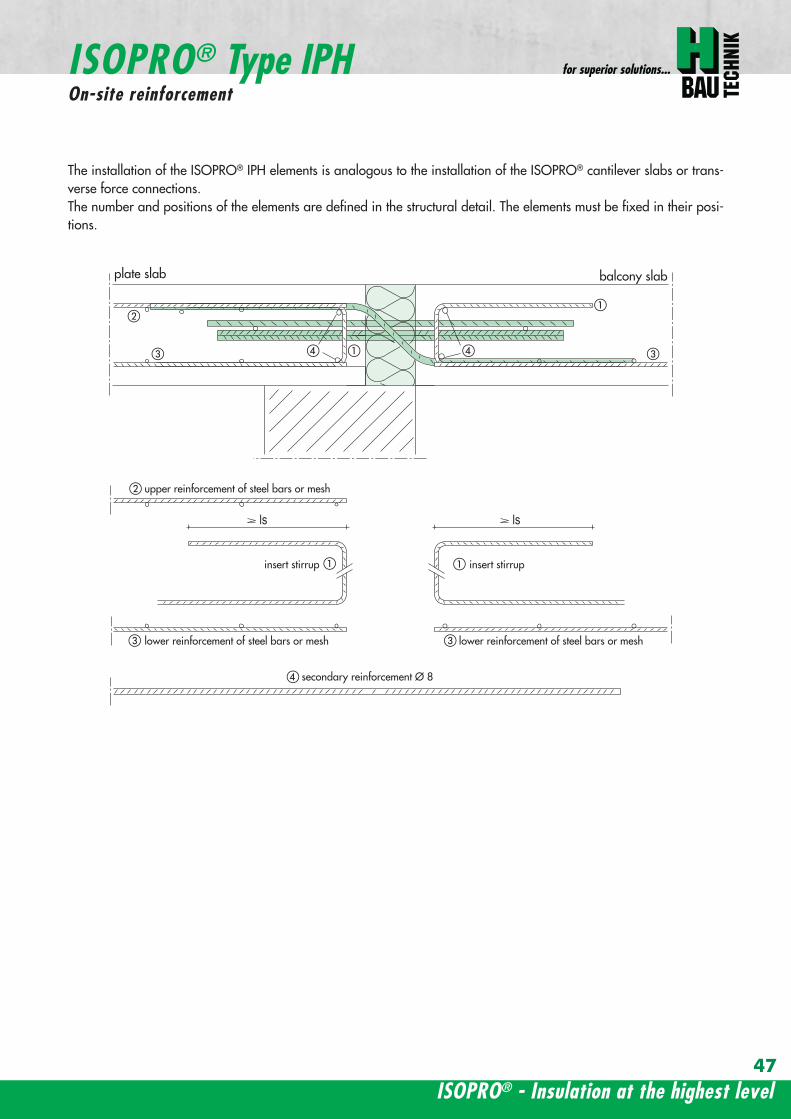
ISOPROreg - Insulation at the highest level
for superior solutions
47
ISOPROreg Type IPHOn-site reinforcement
The installation of the ISOPROreg IPH elements is analogous to the installation of the ISOPROreg cantilever slabs or trans-verse force connectionsThe number and positions of the elements are defined in the structural detail The elements must be fixed in their posi-tions
plate slab balcony slab
ls ls
lower reinforcement of steel bars or mesh
d
lower reinforcement of steel bars or mesh
upper reinforcement of steel bars or mesh
a
aa
dc
d
insert stirrup
a
b
c
secondary reinforcement Oslash 8
b
c c
insert stirrup
wwwh-baucom48
ISOPROreg Type IPAConstruction and calculation values
29
0204
0608
1012
1416
1820
2422
2628
0204
0608
1012
1416
1820
2224
2628
0 +10 +20 +30 +40 +50-10-20-30-40-50
dimensioning axis
MEd
VEd
NEd
380
60
gt160
sup3 16
0
130
Section
Mathematical model ndash Static system Interaction diagram
NRd [kN]
M Rd[kNm]
DimensionsLength of element 350 mmFascia thickness 160 ndash 240 mmHeight of element from 160 mmThickness of insulation element 60 mm
ReinforcementTension rods 3 Oslash 8Compression rods 3 Oslash 8Transverse force rods 2 x 2 Oslash 6
Calculated values for NRd = 0MRd 29 kNmelementVRd plusmn 127 kNelement
ISOPROreg - Insulation at the highest level
for superior solutions
49
ISOPROreg Type IPAOn-site reinforcement and installation instructions
400
100
aa
bc
b c
dd
e
f
gh
h
e
g
h
f
inse
rt s
tirru
ps
conn
ectio
n re
info
rcem
ent
conn
ectio
n re
info
rcem
ent
steel bar Oslash 8
upper slab reinforcement
insert stirrups 3 Oslash 8 150 mmsupplied
insert stirrup as constructive edging
lower slab reinforcement
34
160
56 59 60 60 59 56
34
Section Plan
Installation instructions1 Lay lower reinforcement including edging
2 Install ISOPROreg elements type IPA Spacing in accordance with static requirements
3 Install positions and and tie together
4 Lay upper floor reinforcement and tie together with the ISOPROreg reinforcement element
5 Concrete the floor slab Ensure safe positioning
6 Attach the on-site insulation between the ISOPROreg elements
7 Lay the fascia reinforcement and including edging and tie together with the ISOPROreg elements
supplied insulation
Type IPAType IPA
350e = separation of elements
gt 80
gt 16
0
Spacing of the elements Spacing of expansion joints
Expansion joint spacing e le 78 mAbove corner e2 le 35 m
The parapet must be verified as being a continuous supporte = spacing of the elements in accordance with static requirements
wwwh-baucom50
+5 +15 +25 +35-5-15-25-35
05
10
15
0
MEd
NEdVEd
MRdVRd
dimensioning axis
ISOPROreg Type IPFConstruction and calculation values
42034
0
60
100
Section
Mathematical model ndash Static system Interaction diagram
DimensionsLength of element 350 mmHeight of element from 160 mmThickness of insulation element 60 mm
ReinforcementTension rods 3 Oslash 6Compression rods 3 Oslash 6Transverse force rods 2 Oslash 6
Calculated values for NRd = 0MRd plusmn 15 kNmelementVRd + 127 kNelement
NRd [kN]
M Rd[kN
m]
VRd = 127 kN
ISOPROreg - Insulation at the highest level
for superior solutions
51
ISOPROreg Type IPFOn-site reinforcement and installation instructions
b
a insert stirrup min Oslash 6 150 mm
upper slab reinforcement
ac
b
e
d
c lower slab reinforcement
est
eel b
ar Oslash
8
d2
inse
rt s
tirru
p m
in Oslash
6
150
mm
3333
56 59 60 60 59 56
160
350
Section
Plan
Installation instructions1 Lay lower reinforcement including edging
2 Install ISOPROreg elements type IPA Spacing in accordance with static requirements
3 Install positions and and tie together
4 Lay upper floor reinforcement and tie together with the ISOPROreg reinforcement element
5 Concrete the floor slab Ensure safe positioning
6 Attach the on-site insulation between the ISOPROreg elements
7 Lay the fascia reinforcement and including edging and tie together with the ISOPROreg elements
350
60
Type IPF Type IPF
e = separation of elements
supplied insulation
parapet
Spacing of the elements
Spacing of expansion joints
Expansion joint spacing e le 78 mAbove corner e2 le 35 m
The parapet must be verified as beinga continuous support e = spacing of the elements in accor-dance with static requirements
wwwh-baucom52
ISOPROreg Type IPOConstruction and calculation values
23 lK
+PRd
+HEd
lK
sliding film
reinforcedconcrete console
soft-fibre panel
sup3 18
0
sup3 150 60
725
130 60 535
350
sliding film
reinforcedconcrete console
soft-fibre panelsup3
180
sup3 150 60
725
130 60 535
350
Section
Plan Mathematical modelStatic system
DimensionsLength of element 350 mmHeight of element from 180 mmThickness of insulation element 60 mm
ReinforcementTension rods 3 Oslash 6Compression rods 3 Oslash 8Transverse force rods 2 Oslash 10
for Hed = 0 PRd plusmn 171 kNmelement max HRd + 184 kNelement
0 2 4 6 8 10 12 14 16 20 22 Horizontal force HEd [kN]
25
15
10
5
0
P Rd[kN] concrete gege C2530
concrete gege C2025
PRd = 23
PRd = 10
HEd
= 18
4
HEd
= 23
1
ISOPROreg - Insulation at the highest level
for superior solutions
53
ISOPROreg Type IPOOn-site reinforcement and installation instructions
slab
a
a
bde
b
c
c upper reinforcement of steel bars or mesh
lower reinforcement of steel bars or mesh
insert stirrupde
long
itudi
nal r
einf
orce
men
t
clos
ed s
tirru
p
concrete
concrete
Section Installation instructions
1 Lay lower reinforcement including edging
2 Install ISOPROreg elements type IPO Spacingin accordance with static requirements
3 Lay upper floor reinforcement and tie to-gether with the ISOPROreg reinforcement ele-ment
4 Attach the on-site insulation between the ISO-PROreg elements
5 Lay the console reinforcement and andtie together with the ISOPROreg elements Thefloor edge beam must be designed as a con-tinuous support
6 As far as practical the console and the floorshould be concreted simultaneously Ensuresecure positioning
reinforced concrete joist
ISOPRO Type IPO ISOPRO Type IPO
supplied insulation
e = separation of elements350
Spacing of the elements Spacing of expansion joints
Expansion joint spacing e le 78 mAbove corner e2 le 35 m
The parapet must be verified as being a continuous support e = spacing of the elements in accordance with static requirements
wwwh-baucom54
ISOPROreg Type IPSConstruction and calculation values
80
5050
80 ZL
balcony slab plate slab
wall
console
tension rod
transverse force bars
compression strut
ZL
QL
QL
DL
80
DL
100100
BSt 500 Nr Wst Nr 14571
BSt 500 Nr Wst Nr 14571
BSt 500 S
BSt 500 S
Section
80
5050
80 ZL
balcony slab plate slab
wall
console
tension rod
transverse force bars
compression strut
ZL
QL
QL
DL
80
DL
100100
BSt 500 Nr Wst Nr 14571
BSt 500 Nr Wst Nr 14571
BSt 500 S
BSt 500 S
Dimensions - Type IPS [length in mm]
Type Tension rod Transverse forcerod
Compressionrod
ZL QL DLIPS 1 690 500 430IPS 2 820 620 500IPS 3 960 745 570IPS 4 1550 865 600
Dimensioning table for concrete gege C2025Element hight 400 mm IPS 1 IPS 2 IPS 3 IPS 4
moment MRd [kNm] 221 294 375 624
transverse forces VRd [kN] 213 333 480 653
Type IPS 1 IPS 2 IPS 3 IPS 4
Element width [mm] 220 220 220 220
Tension rods 3 Oslash 10 3 Oslash 12 3 Oslash 14 4 Oslash 14
Transverse force rods 2 Oslash 8 2 Oslash 10 2 Oslash 12 2 Oslash 14
Compression rods 3 Oslash 12 3 Oslash 14 3 Oslash 16 3 Oslash 20
Other designs and dimensions are available on requestThe bonding area I underlies the determination of the anchoring lengths However if required the reinforcement rods can also be designed for bonding area II
Configuration of the elements
ISOPROreg - Insulation at the highest level
for superior solutions
55
ISOPROreg Type IPSOn-site reinforcement and installation instructions
wall plate reinforcement to structural calculations
tension rod
transverse force bars
compression strut
a
b
c
d
d
a
b
a closed stirrup
edging
c suspension reinforcementconcrete concrete
Installation instructions
1 Lay wall plate reinforcement to meet structural requirements2 Insert ISOPROreg element type IPS and tie together with the wall
reinforcement Transverse reinforcement in overlap zone in accordance with DIN 1045-1
3 Install and tie together beam reinforcement and according to structural calculations Pos edging in accordance withDIN 1045-1 Pos installed as a closed stirrup to avoid shearing
4 When concreting make sure that both sides are uniformly filled and compacted
5 Formwork offset for the beam in accordance with structural calculations
wall plate reinforcement to structural calculations
tension rod
transverse force bars
compression strut
a
b
c
d
d
a
b
a closed stirrup
edging
c suspension reinforcementconcrete concrete
80
b b
plate slab
Type IPS
wal
l pla
te
Type IPS wal
l pla
te
balcony slab
supplied insulation
Configuration of the elements Expansion joint spacing
TypeJoint spacing [m]
e
IPS 1 113
IPS 2 101
IPS 3 92
IPS 4 80
For corner constructions the maximumrod leg length is e2
wwwh-baucom56
ISOPROreg Type IPWConstruction and calculation values
ZL ZL80
420 420
QL QL
DL DL
290290
low
er s
ectio
n12
50ce
ntre
sec
tion
uppe
r se
ctio
n25
0
h =
150
- 3
50
m
80
balcony
balcony slab
slab
exte
rnal
wal
l
inte
rnal
wal
l
horizontal transverse force bars
horizontal transverse force bars
upper section bht in mm150-250 250 80
lower section bht in mm150-250 1250 80
Section
Table of Dimensions Type IPW [length in mm]
Type
Tension rod Transverseforce rod
Compressionrod
ZL QL DLIPW 1 600 423 270IPW 2 790 563 335IPW 3 980 653 410IPW 4 1170 783 470
Element width b = 150 ndash 250 mmElement height h = 150 ndash 350 mInsulation material thickness t = 80 mm
Dimensioning table for concrete gege C2025Calculated values for acceptable moments MRdy [kNm]
Element height [m] IPW 1 IPW 2 IPW 3 IPW 415 ndash 20 537 918 1169 154420 ndash 25 737 1267 1614 2132
gt 25 937 1616 2059 2720Calculated values for acceptable transverse forces [kN]
vRdz [kN] 412 622 1066 1535vRdy [kN] plusmn137 plusmn137 plusmn137 plusmn137
Type IPW 1 IPW 2 IPW 3 IPW 4Element height [m] ge150 ge150 ge150 ge150Tension rods 4 Oslash 6 4 Oslash 8 4 Oslash 10 4 Oslash 12Transverse force rods Qz 6 Oslash 6 6 Oslash 8 6 Oslash 10 6 Oslash 12Transverse force rods Qy 2 x 2 Oslash 6 2 x 2 Oslash 6 2 x 2 Oslash 6 2 x 2 Oslash 6Compression rods 6 Oslash 8 6 Oslash 10 6 Oslash 12 6 Oslash 14
Configuration of the elements
Moment effects from wind loading are absorbed bythe stiffening effect of the balcony slab
MRdz = 0
Bonding area II underlies the determination of theoverlap lengths On request the anchoring lengthscan also be dimensioned for bonding area I Designsand dimensions deviating from the standard ele-ments are available on request
ISOPROreg - Insulation at the highest level
for superior solutions
57
ISOPROreg Type IPWOn-site reinforcement and installation instructions
MRdz
VRdz VRdy
x
z
y
MRdy
Mathematical model ndash Static system
balcony slab
balcony slab
steel
mes
h re
info
rcem
ent
a
steel
mes
h re
info
rcem
ent
b
e connection reinforcementto structural calculations
f
insert stirrupas constructive edging c
c
d steel bar min 2 Oslash 8
concrete sup3 2025
exte
rnal
wal
l
inte
rnal
wal
l
insert stirrupas constructive edging
connection reinforcementto structural calculations
a bc c
d
d
steel bar min 2 Oslash 8
steel bar min 2 Oslash 8
insert stirrupinsert stirrupsteel mesh reinforcement steel mesh reinforcement
80
wall p
late
wall p
late
balcony slab
plate slab
Type IPWsupplied insulation
Type IPW
b b
e e e
Configuration of the elements
Installation instructions
1 Position internal wall reinforcement 2 Attach the constructive edging inter-
nally (insert stirrup)3 Starting at the bottom assemble the in-
dividual ISOPROreg elements type IPWand tie together with the wall reinforce-ment
4 Erect and internally and tie to-gether
5 Position the external wall reinforce-ments and in accordancewith structural design and tie to theISOPROreg elements
6 When concreting pay particular atten-tion to the positional security of the ele-ments It is recommended to fill andcompact both wall plates at the sametime
wwwh-baucom58
ISOPROreg
Approvals and Type testing
Approvals
ISOPRO Type IP Z-157-244ISOPRO Type IPT Z-157-243
Type testing
ISOPRO Type IP Test No 0517ISOPRO Type IPT Test No 0518ISOPRO Type IPQ Test No 0519
ISOPROreg - Insulation at the highest level
for superior solutions
59
ISOPROreg
Tender
___________________________________________________________________________
Scope Application area DIN 276013 Concrete and reinforced concrete Floor constructions
Structural installations__________________________________________________________________________________
ISOPROreg supporting and thermally insulating connection elements
01 supporting the balcony slab using ISOPROreg elements from H-BAU Technik GmbH02 required for installation03 m Type IP cv = mm h = mm04 m Type IPQ cv = mm h = mm05 part Type cv = mm h = mm
Special fabrication according to the following description
06 for thermal separation of the concrete07 for the storey floors pos 08 for the roofing pos 09 for 10 and11 for the balcony slap pos 12 for the loggia slab pos 13 for the cantilever slab pos 14 for the 15 in fire protection construction class F9016 the bonding is made in the reinforcement of pos and pos 17 deliver18 deliver install and bond with the connection reinforcement19 only install and bond with the connection reinforcement delivery provided20 the installation is made in accordance with instructions from
H-BAU Technik GmbHAm Guumlterbahnhof 2079771 Klettgau-ErzingenGermanyTel +49 (0) 77 42 92 15-20Fax +49 (0) 77 42 92 15-90
21 in accordance with the detail and reinforcement drawings no 22 material 23 wages 24 unit price
25 total price
wwwh-baucom60
NOTES
ISOPROreg - Insulation at the highest level
for superior solutions
61
NOTES
wwwh-baucom
Concreting with system
ISOPROreg
KESIIRAPIDOBATreg
JSDHEDFERBOXreg
BOXFERreg
GRIPRIPreg
PENTAFLEXreg
RIPINOXreg
WARMBORDreg
SCHALBORDreg
ZEMBORDreg
SCHALL-ISO ACCESSORIES
H-BAU Technik GmbHAm Guumlterbahnhof 20D-79771 Klettgau-ErzingenTel + 49 (0) 7742 92 15-20Fax + 49 (0) 7742 92 15-90infoklettgauh-baude
Produktion Nord-OstBrandenburger StraszligeD-14641 WachowTel + 49 (0) 3 3239 775-20Fax + 49 (0) 3 3239 775-90infoberlinh-baude
Balcony insulation elementsLifting anchorsShuttering tubesPush-in pegsReinforcement connectorsReinforcement connectorsMasonry connectorsSealing technologyRustproof stainless steelStop end panelsStop end panelsStop end panelsSound insulation elementsSpacers
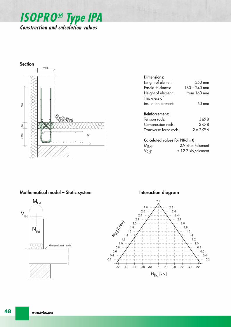

ISOPROreg - Insulation at the highest level
for superior solutions
49
ISOPROreg Type IPAOn-site reinforcement and installation instructions
400
100
aa
bc
b c
dd
e
f
gh
h
e
g
h
f
inse
rt s
tirru
ps
conn
ectio
n re
info
rcem
ent
conn
ectio
n re
info
rcem
ent
steel bar Oslash 8
upper slab reinforcement
insert stirrups 3 Oslash 8 150 mmsupplied
insert stirrup as constructive edging
lower slab reinforcement
34
160
56 59 60 60 59 56
34
Section Plan
Installation instructions1 Lay lower reinforcement including edging
2 Install ISOPROreg elements type IPA Spacing in accordance with static requirements
3 Install positions and and tie together
4 Lay upper floor reinforcement and tie together with the ISOPROreg reinforcement element
5 Concrete the floor slab Ensure safe positioning
6 Attach the on-site insulation between the ISOPROreg elements
7 Lay the fascia reinforcement and including edging and tie together with the ISOPROreg elements
supplied insulation
Type IPAType IPA
350e = separation of elements
gt 80
gt 16
0
Spacing of the elements Spacing of expansion joints
Expansion joint spacing e le 78 mAbove corner e2 le 35 m
The parapet must be verified as being a continuous supporte = spacing of the elements in accordance with static requirements
wwwh-baucom50
+5 +15 +25 +35-5-15-25-35
05
10
15
0
MEd
NEdVEd
MRdVRd
dimensioning axis
ISOPROreg Type IPFConstruction and calculation values
42034
0
60
100
Section
Mathematical model ndash Static system Interaction diagram
DimensionsLength of element 350 mmHeight of element from 160 mmThickness of insulation element 60 mm
ReinforcementTension rods 3 Oslash 6Compression rods 3 Oslash 6Transverse force rods 2 Oslash 6
Calculated values for NRd = 0MRd plusmn 15 kNmelementVRd + 127 kNelement
NRd [kN]
M Rd[kN
m]
VRd = 127 kN
ISOPROreg - Insulation at the highest level
for superior solutions
51
ISOPROreg Type IPFOn-site reinforcement and installation instructions
b
a insert stirrup min Oslash 6 150 mm
upper slab reinforcement
ac
b
e
d
c lower slab reinforcement
est
eel b
ar Oslash
8
d2
inse
rt s
tirru
p m
in Oslash
6
150
mm
3333
56 59 60 60 59 56
160
350
Section
Plan
Installation instructions1 Lay lower reinforcement including edging
2 Install ISOPROreg elements type IPA Spacing in accordance with static requirements
3 Install positions and and tie together
4 Lay upper floor reinforcement and tie together with the ISOPROreg reinforcement element
5 Concrete the floor slab Ensure safe positioning
6 Attach the on-site insulation between the ISOPROreg elements
7 Lay the fascia reinforcement and including edging and tie together with the ISOPROreg elements
350
60
Type IPF Type IPF
e = separation of elements
supplied insulation
parapet
Spacing of the elements
Spacing of expansion joints
Expansion joint spacing e le 78 mAbove corner e2 le 35 m
The parapet must be verified as beinga continuous support e = spacing of the elements in accor-dance with static requirements
wwwh-baucom52
ISOPROreg Type IPOConstruction and calculation values
23 lK
+PRd
+HEd
lK
sliding film
reinforcedconcrete console
soft-fibre panel
sup3 18
0
sup3 150 60
725
130 60 535
350
sliding film
reinforcedconcrete console
soft-fibre panelsup3
180
sup3 150 60
725
130 60 535
350
Section
Plan Mathematical modelStatic system
DimensionsLength of element 350 mmHeight of element from 180 mmThickness of insulation element 60 mm
ReinforcementTension rods 3 Oslash 6Compression rods 3 Oslash 8Transverse force rods 2 Oslash 10
for Hed = 0 PRd plusmn 171 kNmelement max HRd + 184 kNelement
0 2 4 6 8 10 12 14 16 20 22 Horizontal force HEd [kN]
25
15
10
5
0
P Rd[kN] concrete gege C2530
concrete gege C2025
PRd = 23
PRd = 10
HEd
= 18
4
HEd
= 23
1
ISOPROreg - Insulation at the highest level
for superior solutions
53
ISOPROreg Type IPOOn-site reinforcement and installation instructions
slab
a
a
bde
b
c
c upper reinforcement of steel bars or mesh
lower reinforcement of steel bars or mesh
insert stirrupde
long
itudi
nal r
einf
orce
men
t
clos
ed s
tirru
p
concrete
concrete
Section Installation instructions
1 Lay lower reinforcement including edging
2 Install ISOPROreg elements type IPO Spacingin accordance with static requirements
3 Lay upper floor reinforcement and tie to-gether with the ISOPROreg reinforcement ele-ment
4 Attach the on-site insulation between the ISO-PROreg elements
5 Lay the console reinforcement and andtie together with the ISOPROreg elements Thefloor edge beam must be designed as a con-tinuous support
6 As far as practical the console and the floorshould be concreted simultaneously Ensuresecure positioning
reinforced concrete joist
ISOPRO Type IPO ISOPRO Type IPO
supplied insulation
e = separation of elements350
Spacing of the elements Spacing of expansion joints
Expansion joint spacing e le 78 mAbove corner e2 le 35 m
The parapet must be verified as being a continuous support e = spacing of the elements in accordance with static requirements
wwwh-baucom54
ISOPROreg Type IPSConstruction and calculation values
80
5050
80 ZL
balcony slab plate slab
wall
console
tension rod
transverse force bars
compression strut
ZL
QL
QL
DL
80
DL
100100
BSt 500 Nr Wst Nr 14571
BSt 500 Nr Wst Nr 14571
BSt 500 S
BSt 500 S
Section
80
5050
80 ZL
balcony slab plate slab
wall
console
tension rod
transverse force bars
compression strut
ZL
QL
QL
DL
80
DL
100100
BSt 500 Nr Wst Nr 14571
BSt 500 Nr Wst Nr 14571
BSt 500 S
BSt 500 S
Dimensions - Type IPS [length in mm]
Type Tension rod Transverse forcerod
Compressionrod
ZL QL DLIPS 1 690 500 430IPS 2 820 620 500IPS 3 960 745 570IPS 4 1550 865 600
Dimensioning table for concrete gege C2025Element hight 400 mm IPS 1 IPS 2 IPS 3 IPS 4
moment MRd [kNm] 221 294 375 624
transverse forces VRd [kN] 213 333 480 653
Type IPS 1 IPS 2 IPS 3 IPS 4
Element width [mm] 220 220 220 220
Tension rods 3 Oslash 10 3 Oslash 12 3 Oslash 14 4 Oslash 14
Transverse force rods 2 Oslash 8 2 Oslash 10 2 Oslash 12 2 Oslash 14
Compression rods 3 Oslash 12 3 Oslash 14 3 Oslash 16 3 Oslash 20
Other designs and dimensions are available on requestThe bonding area I underlies the determination of the anchoring lengths However if required the reinforcement rods can also be designed for bonding area II
Configuration of the elements
ISOPROreg - Insulation at the highest level
for superior solutions
55
ISOPROreg Type IPSOn-site reinforcement and installation instructions
wall plate reinforcement to structural calculations
tension rod
transverse force bars
compression strut
a
b
c
d
d
a
b
a closed stirrup
edging
c suspension reinforcementconcrete concrete
Installation instructions
1 Lay wall plate reinforcement to meet structural requirements2 Insert ISOPROreg element type IPS and tie together with the wall
reinforcement Transverse reinforcement in overlap zone in accordance with DIN 1045-1
3 Install and tie together beam reinforcement and according to structural calculations Pos edging in accordance withDIN 1045-1 Pos installed as a closed stirrup to avoid shearing
4 When concreting make sure that both sides are uniformly filled and compacted
5 Formwork offset for the beam in accordance with structural calculations
wall plate reinforcement to structural calculations
tension rod
transverse force bars
compression strut
a
b
c
d
d
a
b
a closed stirrup
edging
c suspension reinforcementconcrete concrete
80
b b
plate slab
Type IPS
wal
l pla
te
Type IPS wal
l pla
te
balcony slab
supplied insulation
Configuration of the elements Expansion joint spacing
TypeJoint spacing [m]
e
IPS 1 113
IPS 2 101
IPS 3 92
IPS 4 80
For corner constructions the maximumrod leg length is e2
wwwh-baucom56
ISOPROreg Type IPWConstruction and calculation values
ZL ZL80
420 420
QL QL
DL DL
290290
low
er s
ectio
n12
50ce
ntre
sec
tion
uppe
r se
ctio
n25
0
h =
150
- 3
50
m
80
balcony
balcony slab
slab
exte
rnal
wal
l
inte
rnal
wal
l
horizontal transverse force bars
horizontal transverse force bars
upper section bht in mm150-250 250 80
lower section bht in mm150-250 1250 80
Section
Table of Dimensions Type IPW [length in mm]
Type
Tension rod Transverseforce rod
Compressionrod
ZL QL DLIPW 1 600 423 270IPW 2 790 563 335IPW 3 980 653 410IPW 4 1170 783 470
Element width b = 150 ndash 250 mmElement height h = 150 ndash 350 mInsulation material thickness t = 80 mm
Dimensioning table for concrete gege C2025Calculated values for acceptable moments MRdy [kNm]
Element height [m] IPW 1 IPW 2 IPW 3 IPW 415 ndash 20 537 918 1169 154420 ndash 25 737 1267 1614 2132
gt 25 937 1616 2059 2720Calculated values for acceptable transverse forces [kN]
vRdz [kN] 412 622 1066 1535vRdy [kN] plusmn137 plusmn137 plusmn137 plusmn137
Type IPW 1 IPW 2 IPW 3 IPW 4Element height [m] ge150 ge150 ge150 ge150Tension rods 4 Oslash 6 4 Oslash 8 4 Oslash 10 4 Oslash 12Transverse force rods Qz 6 Oslash 6 6 Oslash 8 6 Oslash 10 6 Oslash 12Transverse force rods Qy 2 x 2 Oslash 6 2 x 2 Oslash 6 2 x 2 Oslash 6 2 x 2 Oslash 6Compression rods 6 Oslash 8 6 Oslash 10 6 Oslash 12 6 Oslash 14
Configuration of the elements
Moment effects from wind loading are absorbed bythe stiffening effect of the balcony slab
MRdz = 0
Bonding area II underlies the determination of theoverlap lengths On request the anchoring lengthscan also be dimensioned for bonding area I Designsand dimensions deviating from the standard ele-ments are available on request
ISOPROreg - Insulation at the highest level
for superior solutions
57
ISOPROreg Type IPWOn-site reinforcement and installation instructions
MRdz
VRdz VRdy
x
z
y
MRdy
Mathematical model ndash Static system
balcony slab
balcony slab
steel
mes
h re
info
rcem
ent
a
steel
mes
h re
info
rcem
ent
b
e connection reinforcementto structural calculations
f
insert stirrupas constructive edging c
c
d steel bar min 2 Oslash 8
concrete sup3 2025
exte
rnal
wal
l
inte
rnal
wal
l
insert stirrupas constructive edging
connection reinforcementto structural calculations
a bc c
d
d
steel bar min 2 Oslash 8
steel bar min 2 Oslash 8
insert stirrupinsert stirrupsteel mesh reinforcement steel mesh reinforcement
80
wall p
late
wall p
late
balcony slab
plate slab
Type IPWsupplied insulation
Type IPW
b b
e e e
Configuration of the elements
Installation instructions
1 Position internal wall reinforcement 2 Attach the constructive edging inter-
nally (insert stirrup)3 Starting at the bottom assemble the in-
dividual ISOPROreg elements type IPWand tie together with the wall reinforce-ment
4 Erect and internally and tie to-gether
5 Position the external wall reinforce-ments and in accordancewith structural design and tie to theISOPROreg elements
6 When concreting pay particular atten-tion to the positional security of the ele-ments It is recommended to fill andcompact both wall plates at the sametime
wwwh-baucom58
ISOPROreg
Approvals and Type testing
Approvals
ISOPRO Type IP Z-157-244ISOPRO Type IPT Z-157-243
Type testing
ISOPRO Type IP Test No 0517ISOPRO Type IPT Test No 0518ISOPRO Type IPQ Test No 0519
ISOPROreg - Insulation at the highest level
for superior solutions
59
ISOPROreg
Tender
___________________________________________________________________________
Scope Application area DIN 276013 Concrete and reinforced concrete Floor constructions
Structural installations__________________________________________________________________________________
ISOPROreg supporting and thermally insulating connection elements
01 supporting the balcony slab using ISOPROreg elements from H-BAU Technik GmbH02 required for installation03 m Type IP cv = mm h = mm04 m Type IPQ cv = mm h = mm05 part Type cv = mm h = mm
Special fabrication according to the following description
06 for thermal separation of the concrete07 for the storey floors pos 08 for the roofing pos 09 for 10 and11 for the balcony slap pos 12 for the loggia slab pos 13 for the cantilever slab pos 14 for the 15 in fire protection construction class F9016 the bonding is made in the reinforcement of pos and pos 17 deliver18 deliver install and bond with the connection reinforcement19 only install and bond with the connection reinforcement delivery provided20 the installation is made in accordance with instructions from
H-BAU Technik GmbHAm Guumlterbahnhof 2079771 Klettgau-ErzingenGermanyTel +49 (0) 77 42 92 15-20Fax +49 (0) 77 42 92 15-90
21 in accordance with the detail and reinforcement drawings no 22 material 23 wages 24 unit price
25 total price
wwwh-baucom60
NOTES
ISOPROreg - Insulation at the highest level
for superior solutions
61
NOTES
wwwh-baucom
Concreting with system
ISOPROreg
KESIIRAPIDOBATreg
JSDHEDFERBOXreg
BOXFERreg
GRIPRIPreg
PENTAFLEXreg
RIPINOXreg
WARMBORDreg
SCHALBORDreg
ZEMBORDreg
SCHALL-ISO ACCESSORIES
H-BAU Technik GmbHAm Guumlterbahnhof 20D-79771 Klettgau-ErzingenTel + 49 (0) 7742 92 15-20Fax + 49 (0) 7742 92 15-90infoklettgauh-baude
Produktion Nord-OstBrandenburger StraszligeD-14641 WachowTel + 49 (0) 3 3239 775-20Fax + 49 (0) 3 3239 775-90infoberlinh-baude
Balcony insulation elementsLifting anchorsShuttering tubesPush-in pegsReinforcement connectorsReinforcement connectorsMasonry connectorsSealing technologyRustproof stainless steelStop end panelsStop end panelsStop end panelsSound insulation elementsSpacers
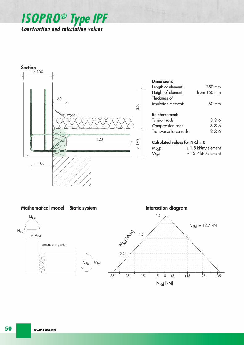
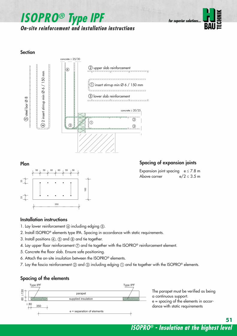
ISOPROreg - Insulation at the highest level
for superior solutions
51
ISOPROreg Type IPFOn-site reinforcement and installation instructions
b
a insert stirrup min Oslash 6 150 mm
upper slab reinforcement
ac
b
e
d
c lower slab reinforcement
est
eel b
ar Oslash
8
d2
inse
rt s
tirru
p m
in Oslash
6
150
mm
3333
56 59 60 60 59 56
160
350
Section
Plan
Installation instructions1 Lay lower reinforcement including edging
2 Install ISOPROreg elements type IPA Spacing in accordance with static requirements
3 Install positions and and tie together
4 Lay upper floor reinforcement and tie together with the ISOPROreg reinforcement element
5 Concrete the floor slab Ensure safe positioning
6 Attach the on-site insulation between the ISOPROreg elements
7 Lay the fascia reinforcement and including edging and tie together with the ISOPROreg elements
350
60
Type IPF Type IPF
e = separation of elements
supplied insulation
parapet
Spacing of the elements
Spacing of expansion joints
Expansion joint spacing e le 78 mAbove corner e2 le 35 m
The parapet must be verified as beinga continuous support e = spacing of the elements in accor-dance with static requirements
wwwh-baucom52
ISOPROreg Type IPOConstruction and calculation values
23 lK
+PRd
+HEd
lK
sliding film
reinforcedconcrete console
soft-fibre panel
sup3 18
0
sup3 150 60
725
130 60 535
350
sliding film
reinforcedconcrete console
soft-fibre panelsup3
180
sup3 150 60
725
130 60 535
350
Section
Plan Mathematical modelStatic system
DimensionsLength of element 350 mmHeight of element from 180 mmThickness of insulation element 60 mm
ReinforcementTension rods 3 Oslash 6Compression rods 3 Oslash 8Transverse force rods 2 Oslash 10
for Hed = 0 PRd plusmn 171 kNmelement max HRd + 184 kNelement
0 2 4 6 8 10 12 14 16 20 22 Horizontal force HEd [kN]
25
15
10
5
0
P Rd[kN] concrete gege C2530
concrete gege C2025
PRd = 23
PRd = 10
HEd
= 18
4
HEd
= 23
1
ISOPROreg - Insulation at the highest level
for superior solutions
53
ISOPROreg Type IPOOn-site reinforcement and installation instructions
slab
a
a
bde
b
c
c upper reinforcement of steel bars or mesh
lower reinforcement of steel bars or mesh
insert stirrupde
long
itudi
nal r
einf
orce
men
t
clos
ed s
tirru
p
concrete
concrete
Section Installation instructions
1 Lay lower reinforcement including edging
2 Install ISOPROreg elements type IPO Spacingin accordance with static requirements
3 Lay upper floor reinforcement and tie to-gether with the ISOPROreg reinforcement ele-ment
4 Attach the on-site insulation between the ISO-PROreg elements
5 Lay the console reinforcement and andtie together with the ISOPROreg elements Thefloor edge beam must be designed as a con-tinuous support
6 As far as practical the console and the floorshould be concreted simultaneously Ensuresecure positioning
reinforced concrete joist
ISOPRO Type IPO ISOPRO Type IPO
supplied insulation
e = separation of elements350
Spacing of the elements Spacing of expansion joints
Expansion joint spacing e le 78 mAbove corner e2 le 35 m
The parapet must be verified as being a continuous support e = spacing of the elements in accordance with static requirements
wwwh-baucom54
ISOPROreg Type IPSConstruction and calculation values
80
5050
80 ZL
balcony slab plate slab
wall
console
tension rod
transverse force bars
compression strut
ZL
QL
QL
DL
80
DL
100100
BSt 500 Nr Wst Nr 14571
BSt 500 Nr Wst Nr 14571
BSt 500 S
BSt 500 S
Section
80
5050
80 ZL
balcony slab plate slab
wall
console
tension rod
transverse force bars
compression strut
ZL
QL
QL
DL
80
DL
100100
BSt 500 Nr Wst Nr 14571
BSt 500 Nr Wst Nr 14571
BSt 500 S
BSt 500 S
Dimensions - Type IPS [length in mm]
Type Tension rod Transverse forcerod
Compressionrod
ZL QL DLIPS 1 690 500 430IPS 2 820 620 500IPS 3 960 745 570IPS 4 1550 865 600
Dimensioning table for concrete gege C2025Element hight 400 mm IPS 1 IPS 2 IPS 3 IPS 4
moment MRd [kNm] 221 294 375 624
transverse forces VRd [kN] 213 333 480 653
Type IPS 1 IPS 2 IPS 3 IPS 4
Element width [mm] 220 220 220 220
Tension rods 3 Oslash 10 3 Oslash 12 3 Oslash 14 4 Oslash 14
Transverse force rods 2 Oslash 8 2 Oslash 10 2 Oslash 12 2 Oslash 14
Compression rods 3 Oslash 12 3 Oslash 14 3 Oslash 16 3 Oslash 20
Other designs and dimensions are available on requestThe bonding area I underlies the determination of the anchoring lengths However if required the reinforcement rods can also be designed for bonding area II
Configuration of the elements
ISOPROreg - Insulation at the highest level
for superior solutions
55
ISOPROreg Type IPSOn-site reinforcement and installation instructions
wall plate reinforcement to structural calculations
tension rod
transverse force bars
compression strut
a
b
c
d
d
a
b
a closed stirrup
edging
c suspension reinforcementconcrete concrete
Installation instructions
1 Lay wall plate reinforcement to meet structural requirements2 Insert ISOPROreg element type IPS and tie together with the wall
reinforcement Transverse reinforcement in overlap zone in accordance with DIN 1045-1
3 Install and tie together beam reinforcement and according to structural calculations Pos edging in accordance withDIN 1045-1 Pos installed as a closed stirrup to avoid shearing
4 When concreting make sure that both sides are uniformly filled and compacted
5 Formwork offset for the beam in accordance with structural calculations
wall plate reinforcement to structural calculations
tension rod
transverse force bars
compression strut
a
b
c
d
d
a
b
a closed stirrup
edging
c suspension reinforcementconcrete concrete
80
b b
plate slab
Type IPS
wal
l pla
te
Type IPS wal
l pla
te
balcony slab
supplied insulation
Configuration of the elements Expansion joint spacing
TypeJoint spacing [m]
e
IPS 1 113
IPS 2 101
IPS 3 92
IPS 4 80
For corner constructions the maximumrod leg length is e2
wwwh-baucom56
ISOPROreg Type IPWConstruction and calculation values
ZL ZL80
420 420
QL QL
DL DL
290290
low
er s
ectio
n12
50ce
ntre
sec
tion
uppe
r se
ctio
n25
0
h =
150
- 3
50
m
80
balcony
balcony slab
slab
exte
rnal
wal
l
inte
rnal
wal
l
horizontal transverse force bars
horizontal transverse force bars
upper section bht in mm150-250 250 80
lower section bht in mm150-250 1250 80
Section
Table of Dimensions Type IPW [length in mm]
Type
Tension rod Transverseforce rod
Compressionrod
ZL QL DLIPW 1 600 423 270IPW 2 790 563 335IPW 3 980 653 410IPW 4 1170 783 470
Element width b = 150 ndash 250 mmElement height h = 150 ndash 350 mInsulation material thickness t = 80 mm
Dimensioning table for concrete gege C2025Calculated values for acceptable moments MRdy [kNm]
Element height [m] IPW 1 IPW 2 IPW 3 IPW 415 ndash 20 537 918 1169 154420 ndash 25 737 1267 1614 2132
gt 25 937 1616 2059 2720Calculated values for acceptable transverse forces [kN]
vRdz [kN] 412 622 1066 1535vRdy [kN] plusmn137 plusmn137 plusmn137 plusmn137
Type IPW 1 IPW 2 IPW 3 IPW 4Element height [m] ge150 ge150 ge150 ge150Tension rods 4 Oslash 6 4 Oslash 8 4 Oslash 10 4 Oslash 12Transverse force rods Qz 6 Oslash 6 6 Oslash 8 6 Oslash 10 6 Oslash 12Transverse force rods Qy 2 x 2 Oslash 6 2 x 2 Oslash 6 2 x 2 Oslash 6 2 x 2 Oslash 6Compression rods 6 Oslash 8 6 Oslash 10 6 Oslash 12 6 Oslash 14
Configuration of the elements
Moment effects from wind loading are absorbed bythe stiffening effect of the balcony slab
MRdz = 0
Bonding area II underlies the determination of theoverlap lengths On request the anchoring lengthscan also be dimensioned for bonding area I Designsand dimensions deviating from the standard ele-ments are available on request
ISOPROreg - Insulation at the highest level
for superior solutions
57
ISOPROreg Type IPWOn-site reinforcement and installation instructions
MRdz
VRdz VRdy
x
z
y
MRdy
Mathematical model ndash Static system
balcony slab
balcony slab
steel
mes
h re
info
rcem
ent
a
steel
mes
h re
info
rcem
ent
b
e connection reinforcementto structural calculations
f
insert stirrupas constructive edging c
c
d steel bar min 2 Oslash 8
concrete sup3 2025
exte
rnal
wal
l
inte
rnal
wal
l
insert stirrupas constructive edging
connection reinforcementto structural calculations
a bc c
d
d
steel bar min 2 Oslash 8
steel bar min 2 Oslash 8
insert stirrupinsert stirrupsteel mesh reinforcement steel mesh reinforcement
80
wall p
late
wall p
late
balcony slab
plate slab
Type IPWsupplied insulation
Type IPW
b b
e e e
Configuration of the elements
Installation instructions
1 Position internal wall reinforcement 2 Attach the constructive edging inter-
nally (insert stirrup)3 Starting at the bottom assemble the in-
dividual ISOPROreg elements type IPWand tie together with the wall reinforce-ment
4 Erect and internally and tie to-gether
5 Position the external wall reinforce-ments and in accordancewith structural design and tie to theISOPROreg elements
6 When concreting pay particular atten-tion to the positional security of the ele-ments It is recommended to fill andcompact both wall plates at the sametime
wwwh-baucom58
ISOPROreg
Approvals and Type testing
Approvals
ISOPRO Type IP Z-157-244ISOPRO Type IPT Z-157-243
Type testing
ISOPRO Type IP Test No 0517ISOPRO Type IPT Test No 0518ISOPRO Type IPQ Test No 0519
ISOPROreg - Insulation at the highest level
for superior solutions
59
ISOPROreg
Tender
___________________________________________________________________________
Scope Application area DIN 276013 Concrete and reinforced concrete Floor constructions
Structural installations__________________________________________________________________________________
ISOPROreg supporting and thermally insulating connection elements
01 supporting the balcony slab using ISOPROreg elements from H-BAU Technik GmbH02 required for installation03 m Type IP cv = mm h = mm04 m Type IPQ cv = mm h = mm05 part Type cv = mm h = mm
Special fabrication according to the following description
06 for thermal separation of the concrete07 for the storey floors pos 08 for the roofing pos 09 for 10 and11 for the balcony slap pos 12 for the loggia slab pos 13 for the cantilever slab pos 14 for the 15 in fire protection construction class F9016 the bonding is made in the reinforcement of pos and pos 17 deliver18 deliver install and bond with the connection reinforcement19 only install and bond with the connection reinforcement delivery provided20 the installation is made in accordance with instructions from
H-BAU Technik GmbHAm Guumlterbahnhof 2079771 Klettgau-ErzingenGermanyTel +49 (0) 77 42 92 15-20Fax +49 (0) 77 42 92 15-90
21 in accordance with the detail and reinforcement drawings no 22 material 23 wages 24 unit price
25 total price
wwwh-baucom60
NOTES
ISOPROreg - Insulation at the highest level
for superior solutions
61
NOTES
wwwh-baucom
Concreting with system
ISOPROreg
KESIIRAPIDOBATreg
JSDHEDFERBOXreg
BOXFERreg
GRIPRIPreg
PENTAFLEXreg
RIPINOXreg
WARMBORDreg
SCHALBORDreg
ZEMBORDreg
SCHALL-ISO ACCESSORIES
H-BAU Technik GmbHAm Guumlterbahnhof 20D-79771 Klettgau-ErzingenTel + 49 (0) 7742 92 15-20Fax + 49 (0) 7742 92 15-90infoklettgauh-baude
Produktion Nord-OstBrandenburger StraszligeD-14641 WachowTel + 49 (0) 3 3239 775-20Fax + 49 (0) 3 3239 775-90infoberlinh-baude
Balcony insulation elementsLifting anchorsShuttering tubesPush-in pegsReinforcement connectorsReinforcement connectorsMasonry connectorsSealing technologyRustproof stainless steelStop end panelsStop end panelsStop end panelsSound insulation elementsSpacers
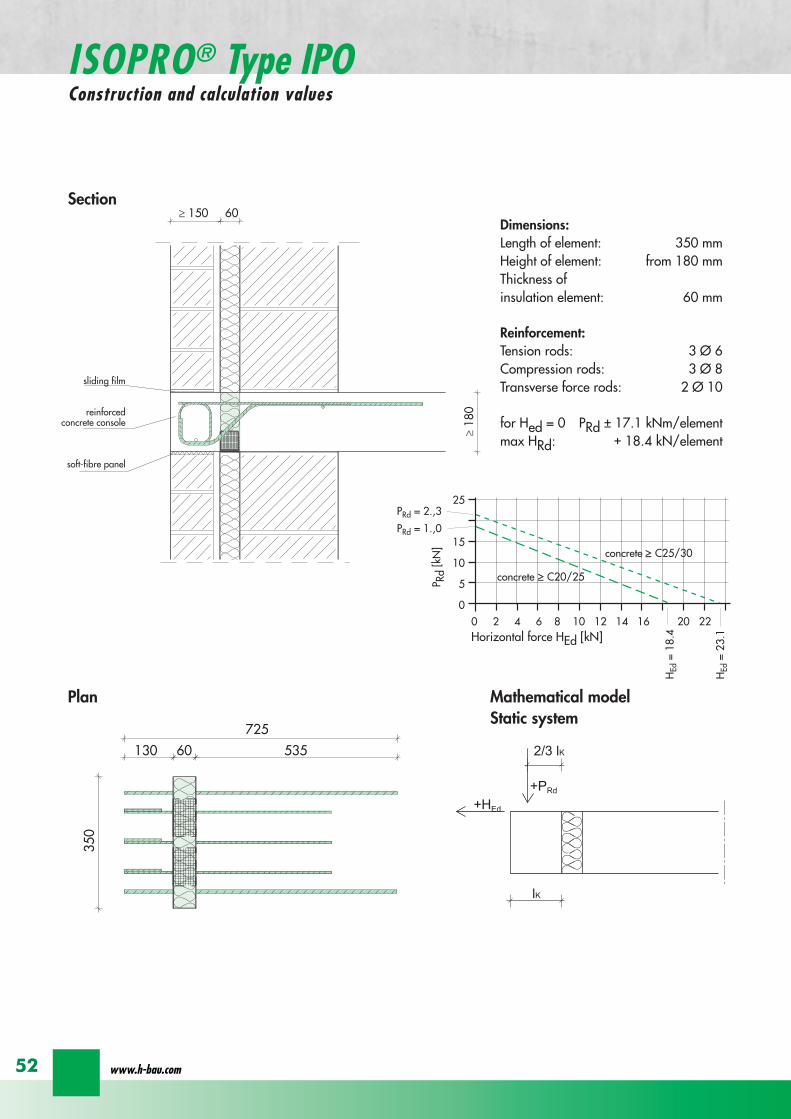
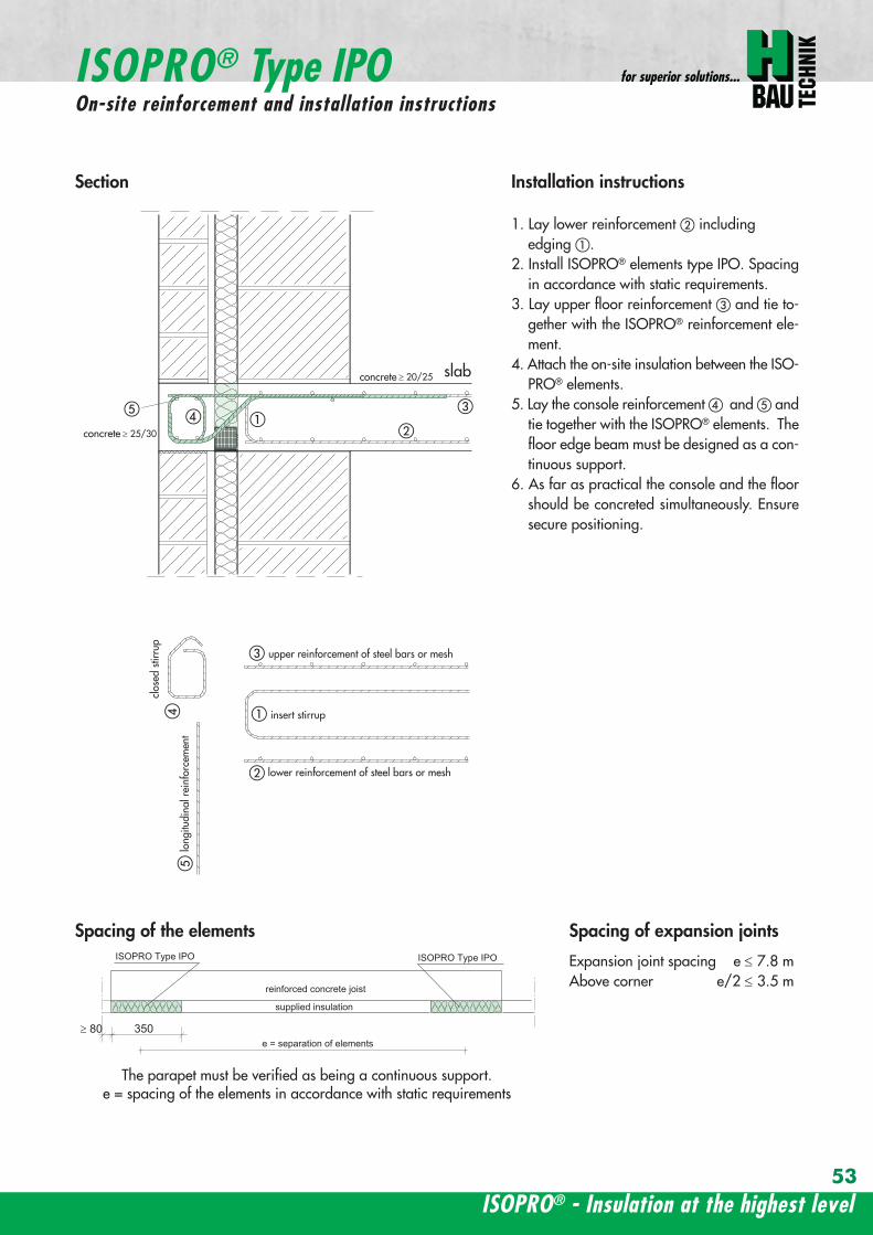
ISOPROreg - Insulation at the highest level
for superior solutions
53
ISOPROreg Type IPOOn-site reinforcement and installation instructions
slab
a
a
bde
b
c
c upper reinforcement of steel bars or mesh
lower reinforcement of steel bars or mesh
insert stirrupde
long
itudi
nal r
einf
orce
men
t
clos
ed s
tirru
p
concrete
concrete
Section Installation instructions
1 Lay lower reinforcement including edging
2 Install ISOPROreg elements type IPO Spacingin accordance with static requirements
3 Lay upper floor reinforcement and tie to-gether with the ISOPROreg reinforcement ele-ment
4 Attach the on-site insulation between the ISO-PROreg elements
5 Lay the console reinforcement and andtie together with the ISOPROreg elements Thefloor edge beam must be designed as a con-tinuous support
6 As far as practical the console and the floorshould be concreted simultaneously Ensuresecure positioning
reinforced concrete joist
ISOPRO Type IPO ISOPRO Type IPO
supplied insulation
e = separation of elements350
Spacing of the elements Spacing of expansion joints
Expansion joint spacing e le 78 mAbove corner e2 le 35 m
The parapet must be verified as being a continuous support e = spacing of the elements in accordance with static requirements
wwwh-baucom54
ISOPROreg Type IPSConstruction and calculation values
80
5050
80 ZL
balcony slab plate slab
wall
console
tension rod
transverse force bars
compression strut
ZL
QL
QL
DL
80
DL
100100
BSt 500 Nr Wst Nr 14571
BSt 500 Nr Wst Nr 14571
BSt 500 S
BSt 500 S
Section
80
5050
80 ZL
balcony slab plate slab
wall
console
tension rod
transverse force bars
compression strut
ZL
QL
QL
DL
80
DL
100100
BSt 500 Nr Wst Nr 14571
BSt 500 Nr Wst Nr 14571
BSt 500 S
BSt 500 S
Dimensions - Type IPS [length in mm]
Type Tension rod Transverse forcerod
Compressionrod
ZL QL DLIPS 1 690 500 430IPS 2 820 620 500IPS 3 960 745 570IPS 4 1550 865 600
Dimensioning table for concrete gege C2025Element hight 400 mm IPS 1 IPS 2 IPS 3 IPS 4
moment MRd [kNm] 221 294 375 624
transverse forces VRd [kN] 213 333 480 653
Type IPS 1 IPS 2 IPS 3 IPS 4
Element width [mm] 220 220 220 220
Tension rods 3 Oslash 10 3 Oslash 12 3 Oslash 14 4 Oslash 14
Transverse force rods 2 Oslash 8 2 Oslash 10 2 Oslash 12 2 Oslash 14
Compression rods 3 Oslash 12 3 Oslash 14 3 Oslash 16 3 Oslash 20
Other designs and dimensions are available on requestThe bonding area I underlies the determination of the anchoring lengths However if required the reinforcement rods can also be designed for bonding area II
Configuration of the elements
ISOPROreg - Insulation at the highest level
for superior solutions
55
ISOPROreg Type IPSOn-site reinforcement and installation instructions
wall plate reinforcement to structural calculations
tension rod
transverse force bars
compression strut
a
b
c
d
d
a
b
a closed stirrup
edging
c suspension reinforcementconcrete concrete
Installation instructions
1 Lay wall plate reinforcement to meet structural requirements2 Insert ISOPROreg element type IPS and tie together with the wall
reinforcement Transverse reinforcement in overlap zone in accordance with DIN 1045-1
3 Install and tie together beam reinforcement and according to structural calculations Pos edging in accordance withDIN 1045-1 Pos installed as a closed stirrup to avoid shearing
4 When concreting make sure that both sides are uniformly filled and compacted
5 Formwork offset for the beam in accordance with structural calculations
wall plate reinforcement to structural calculations
tension rod
transverse force bars
compression strut
a
b
c
d
d
a
b
a closed stirrup
edging
c suspension reinforcementconcrete concrete
80
b b
plate slab
Type IPS
wal
l pla
te
Type IPS wal
l pla
te
balcony slab
supplied insulation
Configuration of the elements Expansion joint spacing
TypeJoint spacing [m]
e
IPS 1 113
IPS 2 101
IPS 3 92
IPS 4 80
For corner constructions the maximumrod leg length is e2
wwwh-baucom56
ISOPROreg Type IPWConstruction and calculation values
ZL ZL80
420 420
QL QL
DL DL
290290
low
er s
ectio
n12
50ce
ntre
sec
tion
uppe
r se
ctio
n25
0
h =
150
- 3
50
m
80
balcony
balcony slab
slab
exte
rnal
wal
l
inte
rnal
wal
l
horizontal transverse force bars
horizontal transverse force bars
upper section bht in mm150-250 250 80
lower section bht in mm150-250 1250 80
Section
Table of Dimensions Type IPW [length in mm]
Type
Tension rod Transverseforce rod
Compressionrod
ZL QL DLIPW 1 600 423 270IPW 2 790 563 335IPW 3 980 653 410IPW 4 1170 783 470
Element width b = 150 ndash 250 mmElement height h = 150 ndash 350 mInsulation material thickness t = 80 mm
Dimensioning table for concrete gege C2025Calculated values for acceptable moments MRdy [kNm]
Element height [m] IPW 1 IPW 2 IPW 3 IPW 415 ndash 20 537 918 1169 154420 ndash 25 737 1267 1614 2132
gt 25 937 1616 2059 2720Calculated values for acceptable transverse forces [kN]
vRdz [kN] 412 622 1066 1535vRdy [kN] plusmn137 plusmn137 plusmn137 plusmn137
Type IPW 1 IPW 2 IPW 3 IPW 4Element height [m] ge150 ge150 ge150 ge150Tension rods 4 Oslash 6 4 Oslash 8 4 Oslash 10 4 Oslash 12Transverse force rods Qz 6 Oslash 6 6 Oslash 8 6 Oslash 10 6 Oslash 12Transverse force rods Qy 2 x 2 Oslash 6 2 x 2 Oslash 6 2 x 2 Oslash 6 2 x 2 Oslash 6Compression rods 6 Oslash 8 6 Oslash 10 6 Oslash 12 6 Oslash 14
Configuration of the elements
Moment effects from wind loading are absorbed bythe stiffening effect of the balcony slab
MRdz = 0
Bonding area II underlies the determination of theoverlap lengths On request the anchoring lengthscan also be dimensioned for bonding area I Designsand dimensions deviating from the standard ele-ments are available on request
ISOPROreg - Insulation at the highest level
for superior solutions
57
ISOPROreg Type IPWOn-site reinforcement and installation instructions
MRdz
VRdz VRdy
x
z
y
MRdy
Mathematical model ndash Static system
balcony slab
balcony slab
steel
mes
h re
info
rcem
ent
a
steel
mes
h re
info
rcem
ent
b
e connection reinforcementto structural calculations
f
insert stirrupas constructive edging c
c
d steel bar min 2 Oslash 8
concrete sup3 2025
exte
rnal
wal
l
inte
rnal
wal
l
insert stirrupas constructive edging
connection reinforcementto structural calculations
a bc c
d
d
steel bar min 2 Oslash 8
steel bar min 2 Oslash 8
insert stirrupinsert stirrupsteel mesh reinforcement steel mesh reinforcement
80
wall p
late
wall p
late
balcony slab
plate slab
Type IPWsupplied insulation
Type IPW
b b
e e e
Configuration of the elements
Installation instructions
1 Position internal wall reinforcement 2 Attach the constructive edging inter-
nally (insert stirrup)3 Starting at the bottom assemble the in-
dividual ISOPROreg elements type IPWand tie together with the wall reinforce-ment
4 Erect and internally and tie to-gether
5 Position the external wall reinforce-ments and in accordancewith structural design and tie to theISOPROreg elements
6 When concreting pay particular atten-tion to the positional security of the ele-ments It is recommended to fill andcompact both wall plates at the sametime
wwwh-baucom58
ISOPROreg
Approvals and Type testing
Approvals
ISOPRO Type IP Z-157-244ISOPRO Type IPT Z-157-243
Type testing
ISOPRO Type IP Test No 0517ISOPRO Type IPT Test No 0518ISOPRO Type IPQ Test No 0519
ISOPROreg - Insulation at the highest level
for superior solutions
59
ISOPROreg
Tender
___________________________________________________________________________
Scope Application area DIN 276013 Concrete and reinforced concrete Floor constructions
Structural installations__________________________________________________________________________________
ISOPROreg supporting and thermally insulating connection elements
01 supporting the balcony slab using ISOPROreg elements from H-BAU Technik GmbH02 required for installation03 m Type IP cv = mm h = mm04 m Type IPQ cv = mm h = mm05 part Type cv = mm h = mm
Special fabrication according to the following description
06 for thermal separation of the concrete07 for the storey floors pos 08 for the roofing pos 09 for 10 and11 for the balcony slap pos 12 for the loggia slab pos 13 for the cantilever slab pos 14 for the 15 in fire protection construction class F9016 the bonding is made in the reinforcement of pos and pos 17 deliver18 deliver install and bond with the connection reinforcement19 only install and bond with the connection reinforcement delivery provided20 the installation is made in accordance with instructions from
H-BAU Technik GmbHAm Guumlterbahnhof 2079771 Klettgau-ErzingenGermanyTel +49 (0) 77 42 92 15-20Fax +49 (0) 77 42 92 15-90
21 in accordance with the detail and reinforcement drawings no 22 material 23 wages 24 unit price
25 total price
wwwh-baucom60
NOTES
ISOPROreg - Insulation at the highest level
for superior solutions
61
NOTES
wwwh-baucom
Concreting with system
ISOPROreg
KESIIRAPIDOBATreg
JSDHEDFERBOXreg
BOXFERreg
GRIPRIPreg
PENTAFLEXreg
RIPINOXreg
WARMBORDreg
SCHALBORDreg
ZEMBORDreg
SCHALL-ISO ACCESSORIES
H-BAU Technik GmbHAm Guumlterbahnhof 20D-79771 Klettgau-ErzingenTel + 49 (0) 7742 92 15-20Fax + 49 (0) 7742 92 15-90infoklettgauh-baude
Produktion Nord-OstBrandenburger StraszligeD-14641 WachowTel + 49 (0) 3 3239 775-20Fax + 49 (0) 3 3239 775-90infoberlinh-baude
Balcony insulation elementsLifting anchorsShuttering tubesPush-in pegsReinforcement connectorsReinforcement connectorsMasonry connectorsSealing technologyRustproof stainless steelStop end panelsStop end panelsStop end panelsSound insulation elementsSpacers
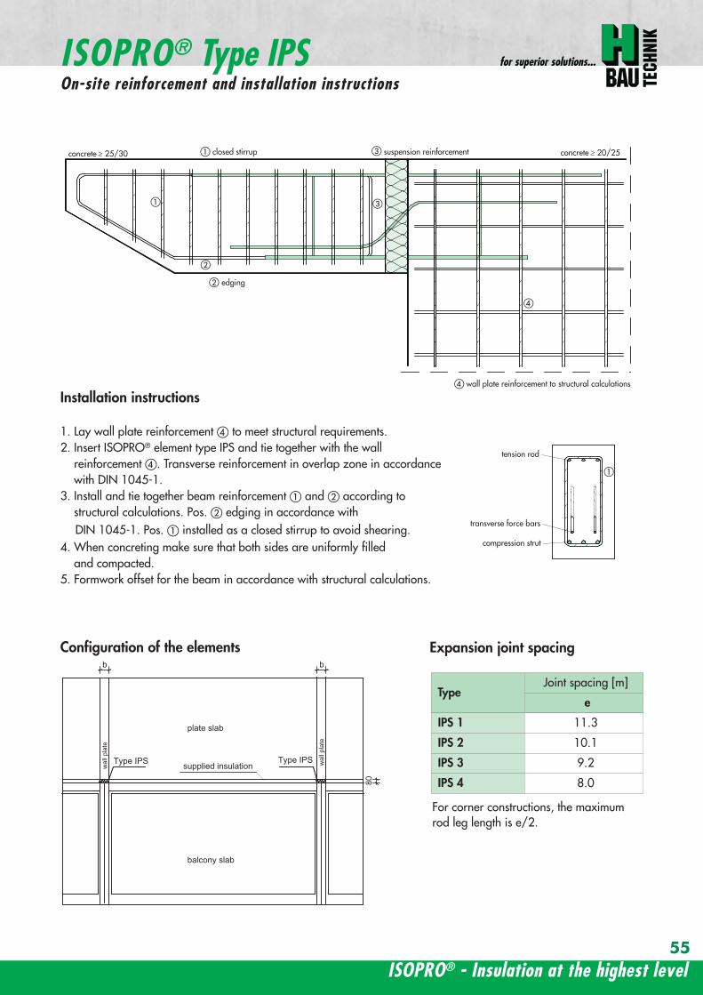
ISOPROreg - Insulation at the highest level
for superior solutions
55
ISOPROreg Type IPSOn-site reinforcement and installation instructions
wall plate reinforcement to structural calculations
tension rod
transverse force bars
compression strut
a
b
c
d
d
a
b
a closed stirrup
edging
c suspension reinforcementconcrete concrete
Installation instructions
1 Lay wall plate reinforcement to meet structural requirements2 Insert ISOPROreg element type IPS and tie together with the wall
reinforcement Transverse reinforcement in overlap zone in accordance with DIN 1045-1
3 Install and tie together beam reinforcement and according to structural calculations Pos edging in accordance withDIN 1045-1 Pos installed as a closed stirrup to avoid shearing
4 When concreting make sure that both sides are uniformly filled and compacted
5 Formwork offset for the beam in accordance with structural calculations
wall plate reinforcement to structural calculations
tension rod
transverse force bars
compression strut
a
b
c
d
d
a
b
a closed stirrup
edging
c suspension reinforcementconcrete concrete
80
b b
plate slab
Type IPS
wal
l pla
te
Type IPS wal
l pla
te
balcony slab
supplied insulation
Configuration of the elements Expansion joint spacing
TypeJoint spacing [m]
e
IPS 1 113
IPS 2 101
IPS 3 92
IPS 4 80
For corner constructions the maximumrod leg length is e2
wwwh-baucom56
ISOPROreg Type IPWConstruction and calculation values
ZL ZL80
420 420
QL QL
DL DL
290290
low
er s
ectio
n12
50ce
ntre
sec
tion
uppe
r se
ctio
n25
0
h =
150
- 3
50
m
80
balcony
balcony slab
slab
exte
rnal
wal
l
inte
rnal
wal
l
horizontal transverse force bars
horizontal transverse force bars
upper section bht in mm150-250 250 80
lower section bht in mm150-250 1250 80
Section
Table of Dimensions Type IPW [length in mm]
Type
Tension rod Transverseforce rod
Compressionrod
ZL QL DLIPW 1 600 423 270IPW 2 790 563 335IPW 3 980 653 410IPW 4 1170 783 470
Element width b = 150 ndash 250 mmElement height h = 150 ndash 350 mInsulation material thickness t = 80 mm
Dimensioning table for concrete gege C2025Calculated values for acceptable moments MRdy [kNm]
Element height [m] IPW 1 IPW 2 IPW 3 IPW 415 ndash 20 537 918 1169 154420 ndash 25 737 1267 1614 2132
gt 25 937 1616 2059 2720Calculated values for acceptable transverse forces [kN]
vRdz [kN] 412 622 1066 1535vRdy [kN] plusmn137 plusmn137 plusmn137 plusmn137
Type IPW 1 IPW 2 IPW 3 IPW 4Element height [m] ge150 ge150 ge150 ge150Tension rods 4 Oslash 6 4 Oslash 8 4 Oslash 10 4 Oslash 12Transverse force rods Qz 6 Oslash 6 6 Oslash 8 6 Oslash 10 6 Oslash 12Transverse force rods Qy 2 x 2 Oslash 6 2 x 2 Oslash 6 2 x 2 Oslash 6 2 x 2 Oslash 6Compression rods 6 Oslash 8 6 Oslash 10 6 Oslash 12 6 Oslash 14
Configuration of the elements
Moment effects from wind loading are absorbed bythe stiffening effect of the balcony slab
MRdz = 0
Bonding area II underlies the determination of theoverlap lengths On request the anchoring lengthscan also be dimensioned for bonding area I Designsand dimensions deviating from the standard ele-ments are available on request
ISOPROreg - Insulation at the highest level
for superior solutions
57
ISOPROreg Type IPWOn-site reinforcement and installation instructions
MRdz
VRdz VRdy
x
z
y
MRdy
Mathematical model ndash Static system
balcony slab
balcony slab
steel
mes
h re
info
rcem
ent
a
steel
mes
h re
info
rcem
ent
b
e connection reinforcementto structural calculations
f
insert stirrupas constructive edging c
c
d steel bar min 2 Oslash 8
concrete sup3 2025
exte
rnal
wal
l
inte
rnal
wal
l
insert stirrupas constructive edging
connection reinforcementto structural calculations
a bc c
d
d
steel bar min 2 Oslash 8
steel bar min 2 Oslash 8
insert stirrupinsert stirrupsteel mesh reinforcement steel mesh reinforcement
80
wall p
late
wall p
late
balcony slab
plate slab
Type IPWsupplied insulation
Type IPW
b b
e e e
Configuration of the elements
Installation instructions
1 Position internal wall reinforcement 2 Attach the constructive edging inter-
nally (insert stirrup)3 Starting at the bottom assemble the in-
dividual ISOPROreg elements type IPWand tie together with the wall reinforce-ment
4 Erect and internally and tie to-gether
5 Position the external wall reinforce-ments and in accordancewith structural design and tie to theISOPROreg elements
6 When concreting pay particular atten-tion to the positional security of the ele-ments It is recommended to fill andcompact both wall plates at the sametime
wwwh-baucom58
ISOPROreg
Approvals and Type testing
Approvals
ISOPRO Type IP Z-157-244ISOPRO Type IPT Z-157-243
Type testing
ISOPRO Type IP Test No 0517ISOPRO Type IPT Test No 0518ISOPRO Type IPQ Test No 0519
ISOPROreg - Insulation at the highest level
for superior solutions
59
ISOPROreg
Tender
___________________________________________________________________________
Scope Application area DIN 276013 Concrete and reinforced concrete Floor constructions
Structural installations__________________________________________________________________________________
ISOPROreg supporting and thermally insulating connection elements
01 supporting the balcony slab using ISOPROreg elements from H-BAU Technik GmbH02 required for installation03 m Type IP cv = mm h = mm04 m Type IPQ cv = mm h = mm05 part Type cv = mm h = mm
Special fabrication according to the following description
06 for thermal separation of the concrete07 for the storey floors pos 08 for the roofing pos 09 for 10 and11 for the balcony slap pos 12 for the loggia slab pos 13 for the cantilever slab pos 14 for the 15 in fire protection construction class F9016 the bonding is made in the reinforcement of pos and pos 17 deliver18 deliver install and bond with the connection reinforcement19 only install and bond with the connection reinforcement delivery provided20 the installation is made in accordance with instructions from
H-BAU Technik GmbHAm Guumlterbahnhof 2079771 Klettgau-ErzingenGermanyTel +49 (0) 77 42 92 15-20Fax +49 (0) 77 42 92 15-90
21 in accordance with the detail and reinforcement drawings no 22 material 23 wages 24 unit price
25 total price
wwwh-baucom60
NOTES
ISOPROreg - Insulation at the highest level
for superior solutions
61
NOTES
wwwh-baucom
Concreting with system
ISOPROreg
KESIIRAPIDOBATreg
JSDHEDFERBOXreg
BOXFERreg
GRIPRIPreg
PENTAFLEXreg
RIPINOXreg
WARMBORDreg
SCHALBORDreg
ZEMBORDreg
SCHALL-ISO ACCESSORIES
H-BAU Technik GmbHAm Guumlterbahnhof 20D-79771 Klettgau-ErzingenTel + 49 (0) 7742 92 15-20Fax + 49 (0) 7742 92 15-90infoklettgauh-baude
Produktion Nord-OstBrandenburger StraszligeD-14641 WachowTel + 49 (0) 3 3239 775-20Fax + 49 (0) 3 3239 775-90infoberlinh-baude
Balcony insulation elementsLifting anchorsShuttering tubesPush-in pegsReinforcement connectorsReinforcement connectorsMasonry connectorsSealing technologyRustproof stainless steelStop end panelsStop end panelsStop end panelsSound insulation elementsSpacers
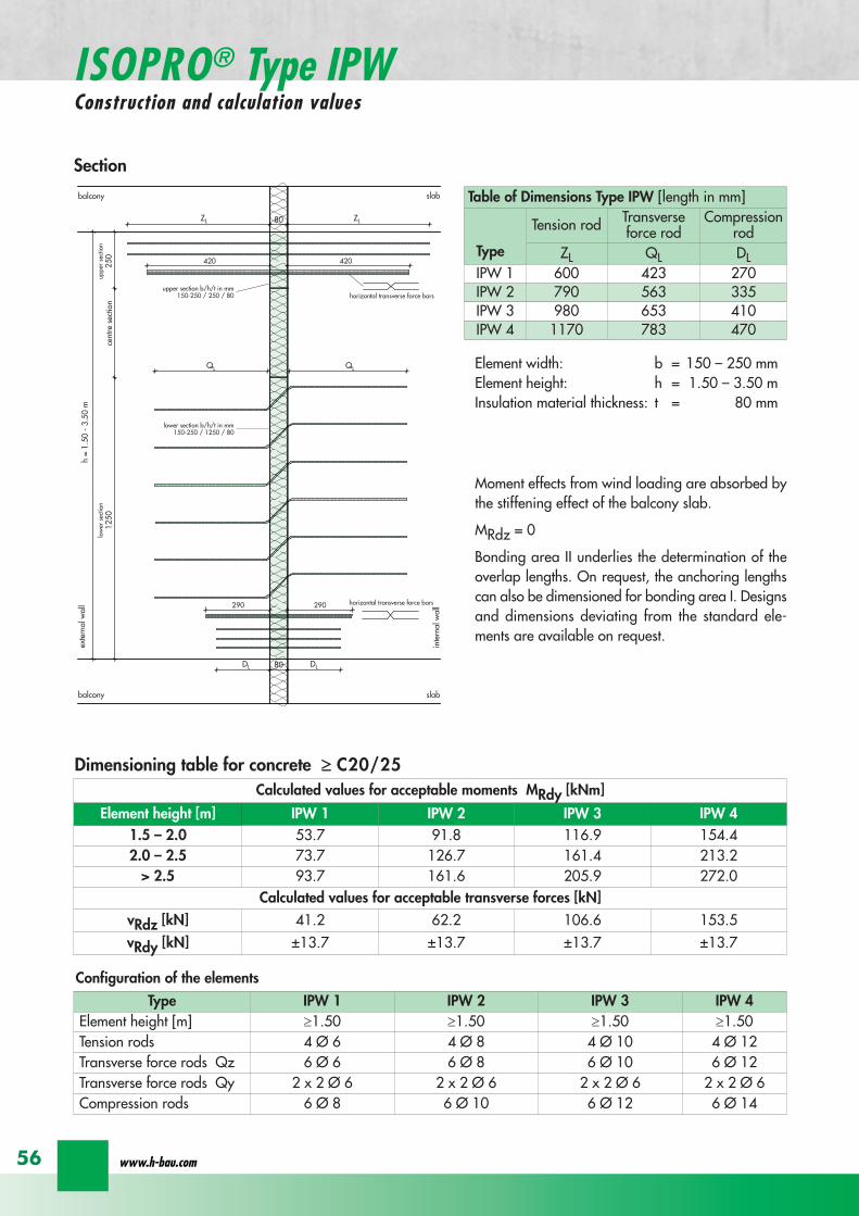
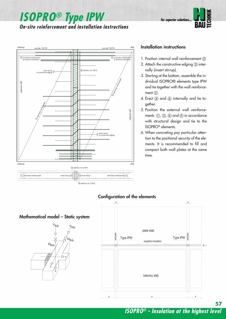
ISOPROreg - Insulation at the highest level
for superior solutions
57
ISOPROreg Type IPWOn-site reinforcement and installation instructions
MRdz
VRdz VRdy
x
z
y
MRdy
Mathematical model ndash Static system
balcony slab
balcony slab
steel
mes
h re
info
rcem
ent
a
steel
mes
h re
info
rcem
ent
b
e connection reinforcementto structural calculations
f
insert stirrupas constructive edging c
c
d steel bar min 2 Oslash 8
concrete sup3 2025
exte
rnal
wal
l
inte
rnal
wal
l
insert stirrupas constructive edging
connection reinforcementto structural calculations
a bc c
d
d
steel bar min 2 Oslash 8
steel bar min 2 Oslash 8
insert stirrupinsert stirrupsteel mesh reinforcement steel mesh reinforcement
80
wall p
late
wall p
late
balcony slab
plate slab
Type IPWsupplied insulation
Type IPW
b b
e e e
Configuration of the elements
Installation instructions
1 Position internal wall reinforcement 2 Attach the constructive edging inter-
nally (insert stirrup)3 Starting at the bottom assemble the in-
dividual ISOPROreg elements type IPWand tie together with the wall reinforce-ment
4 Erect and internally and tie to-gether
5 Position the external wall reinforce-ments and in accordancewith structural design and tie to theISOPROreg elements
6 When concreting pay particular atten-tion to the positional security of the ele-ments It is recommended to fill andcompact both wall plates at the sametime
wwwh-baucom58
ISOPROreg
Approvals and Type testing
Approvals
ISOPRO Type IP Z-157-244ISOPRO Type IPT Z-157-243
Type testing
ISOPRO Type IP Test No 0517ISOPRO Type IPT Test No 0518ISOPRO Type IPQ Test No 0519
ISOPROreg - Insulation at the highest level
for superior solutions
59
ISOPROreg
Tender
___________________________________________________________________________
Scope Application area DIN 276013 Concrete and reinforced concrete Floor constructions
Structural installations__________________________________________________________________________________
ISOPROreg supporting and thermally insulating connection elements
01 supporting the balcony slab using ISOPROreg elements from H-BAU Technik GmbH02 required for installation03 m Type IP cv = mm h = mm04 m Type IPQ cv = mm h = mm05 part Type cv = mm h = mm
Special fabrication according to the following description
06 for thermal separation of the concrete07 for the storey floors pos 08 for the roofing pos 09 for 10 and11 for the balcony slap pos 12 for the loggia slab pos 13 for the cantilever slab pos 14 for the 15 in fire protection construction class F9016 the bonding is made in the reinforcement of pos and pos 17 deliver18 deliver install and bond with the connection reinforcement19 only install and bond with the connection reinforcement delivery provided20 the installation is made in accordance with instructions from
H-BAU Technik GmbHAm Guumlterbahnhof 2079771 Klettgau-ErzingenGermanyTel +49 (0) 77 42 92 15-20Fax +49 (0) 77 42 92 15-90
21 in accordance with the detail and reinforcement drawings no 22 material 23 wages 24 unit price
25 total price
wwwh-baucom60
NOTES
ISOPROreg - Insulation at the highest level
for superior solutions
61
NOTES
wwwh-baucom
Concreting with system
ISOPROreg
KESIIRAPIDOBATreg
JSDHEDFERBOXreg
BOXFERreg
GRIPRIPreg
PENTAFLEXreg
RIPINOXreg
WARMBORDreg
SCHALBORDreg
ZEMBORDreg
SCHALL-ISO ACCESSORIES
H-BAU Technik GmbHAm Guumlterbahnhof 20D-79771 Klettgau-ErzingenTel + 49 (0) 7742 92 15-20Fax + 49 (0) 7742 92 15-90infoklettgauh-baude
Produktion Nord-OstBrandenburger StraszligeD-14641 WachowTel + 49 (0) 3 3239 775-20Fax + 49 (0) 3 3239 775-90infoberlinh-baude
Balcony insulation elementsLifting anchorsShuttering tubesPush-in pegsReinforcement connectorsReinforcement connectorsMasonry connectorsSealing technologyRustproof stainless steelStop end panelsStop end panelsStop end panelsSound insulation elementsSpacers
ISOPROreg - Insulation at the highest level
for superior solutions
59
ISOPROreg
Tender
___________________________________________________________________________
Scope Application area DIN 276013 Concrete and reinforced concrete Floor constructions
Structural installations__________________________________________________________________________________
ISOPROreg supporting and thermally insulating connection elements
01 supporting the balcony slab using ISOPROreg elements from H-BAU Technik GmbH02 required for installation03 m Type IP cv = mm h = mm04 m Type IPQ cv = mm h = mm05 part Type cv = mm h = mm
Special fabrication according to the following description
06 for thermal separation of the concrete07 for the storey floors pos 08 for the roofing pos 09 for 10 and11 for the balcony slap pos 12 for the loggia slab pos 13 for the cantilever slab pos 14 for the 15 in fire protection construction class F9016 the bonding is made in the reinforcement of pos and pos 17 deliver18 deliver install and bond with the connection reinforcement19 only install and bond with the connection reinforcement delivery provided20 the installation is made in accordance with instructions from
H-BAU Technik GmbHAm Guumlterbahnhof 2079771 Klettgau-ErzingenGermanyTel +49 (0) 77 42 92 15-20Fax +49 (0) 77 42 92 15-90
21 in accordance with the detail and reinforcement drawings no 22 material 23 wages 24 unit price
25 total price
wwwh-baucom60
NOTES
ISOPROreg - Insulation at the highest level
for superior solutions
61
NOTES
wwwh-baucom
Concreting with system
ISOPROreg
KESIIRAPIDOBATreg
JSDHEDFERBOXreg
BOXFERreg
GRIPRIPreg
PENTAFLEXreg
RIPINOXreg
WARMBORDreg
SCHALBORDreg
ZEMBORDreg
SCHALL-ISO ACCESSORIES
H-BAU Technik GmbHAm Guumlterbahnhof 20D-79771 Klettgau-ErzingenTel + 49 (0) 7742 92 15-20Fax + 49 (0) 7742 92 15-90infoklettgauh-baude
Produktion Nord-OstBrandenburger StraszligeD-14641 WachowTel + 49 (0) 3 3239 775-20Fax + 49 (0) 3 3239 775-90infoberlinh-baude
Balcony insulation elementsLifting anchorsShuttering tubesPush-in pegsReinforcement connectorsReinforcement connectorsMasonry connectorsSealing technologyRustproof stainless steelStop end panelsStop end panelsStop end panelsSound insulation elementsSpacers


![Profometer PM-6 · 10%-quantile for elements according to DIN 1045-1, table 4 row 1 [R1] (XC1) 5%-quantile for elements according to DIN 1045-1, table 4, rows 2-4 [R1]](https://img.pdfslide.us/doc/110x75/5b4782df7f8b9a501f8cdb82/profometer-pm-6-10-quantile-for-elements-according-to-din-1045-1-table-4-row.jpg)