Embed Size (px)
Citation preview
Thermal Implications for Extreme Fast Charge Matthew Keyser National Renewable Energy Laboratory June 6, 2017 Vehicle Technologies Office (VTO) Annual Merit Review and Peer Evaluation, Washington, D.C.
Project ID # ES306
This presentation does not contain any proprietary, confidential, or otherwise restricted information.
NREL/PR-5400-68339
2
Overview
• Project start date: 8/2016 • Project end date: 12/2016 • Percent complete: 100%
• Decreased battery life at high temperatures
• Cost, size, complexity, and energy consumption of thermal management system during extreme fast charging (XFC)
• Low energy efficiency of high specific energy density cells – advanced chemistries
Timeline Barriers
• National Renewable Energy Laboratory (NREL) o Vehicle Pillar
• Argonne National Laboratory (ANL) o Battery Pillar o Economic Pillar
• Idaho National Laboratory (INL) o Infrastructure Pillar
Partners
Budget • Total project funding
o DOE share: 100% o Contractor share: 0%
• Funding received in FY 2016: $225k • Funding for FY 2017: $0k
3
Relevance of Battery Thermal Implications
Objectives of NREL’s work • Provide feedback to DOE on the battery thermal challenges
associated with XFC • Identify limitations of using high specific energy density cells • Identify state-of-the-art thermal management strategies and how
these can be applied to future battery electric vehicles (BEVs) • Identify thermal areas of concern with present battery systems • Identify how changes to the battery chemistry and cell design
affect the cells’ efficiency and performance • Understand what areas need to be developed to make XFC a
reality.
Life, cost, performance, and safety of energy storage systems are strongly impacted by temperature
4
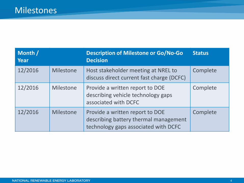
Milestones
Month / Year
Description of Milestone or Go/No-Go Decision
Status
12/2016 Milestone Host stakeholder meeting at NREL to discuss direct current fast charge (DCFC)
Complete
12/2016 Milestone Provide a written report to DOE describing vehicle technology gaps associated with DCFC
Complete
12/2016 Milestone Provide a written report to DOE describing battery thermal management technology gaps associated with DCFC
Complete
5
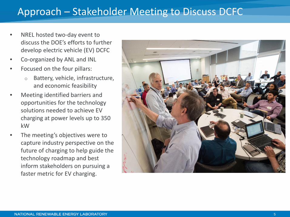
• NREL hosted two-day event to discuss the DOE’s efforts to further develop electric vehicle (EV) DCFC
• Co-organized by ANL and INL • Focused on the four pillars:
o Battery, vehicle, infrastructure, and economic feasibility
• Meeting identified barriers and opportunities for the technology solutions needed to achieve EV charging at power levels up to 350 kW
• The meeting’s objectives were to capture industry perspective on the future of charging to help guide the technology roadmap and best inform stakeholders on pursuing a faster metric for EV charging.
Approach – Stakeholder Meeting to Discuss DCFC
6
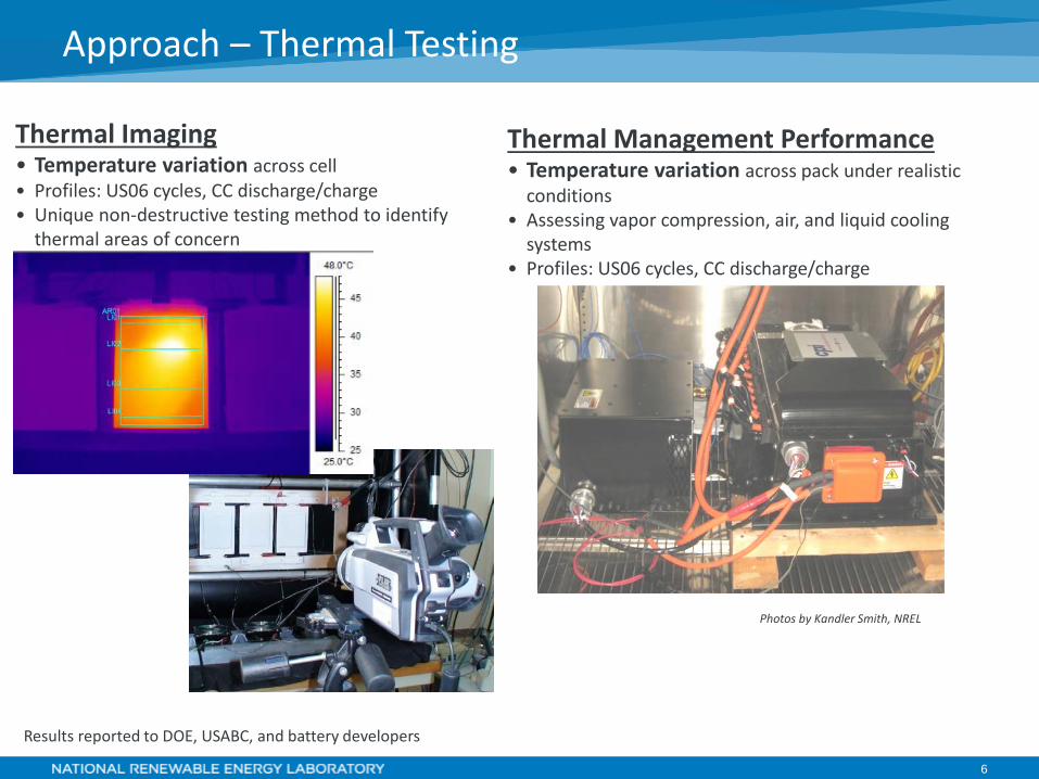
Approach – Thermal Testing
Thermal Imaging • Temperature variation across cell • Profiles: US06 cycles, CC discharge/charge • Unique non-destructive testing method to identify
thermal areas of concern
Results reported to DOE, USABC, and battery developers
Photos by Kandler Smith, NREL
Thermal Management Performance • Temperature variation across pack under realistic
conditions • Assessing vapor compression, air, and liquid cooling
systems • Profiles: US06 cycles, CC discharge/charge
7
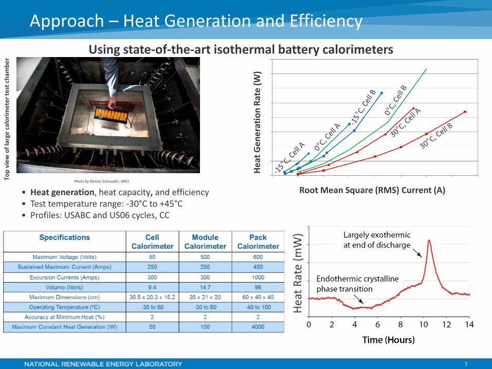
Approach – Heat Generation and Efficiency To
p vi
ew o
f lar
ge c
alor
imet
er te
st c
ham
ber
Hea
t Gen
erat
ion
Rate
(W)
Root Mean Square (RMS) Current (A) • Heat generation, heat capacity, and efficiency • Test temperature range: -30°C to +45°C • Profiles: USABC and US06 cycles, CC
Photo by Dennis Schroeder, NREL
Using state-of-the-art isothermal battery calorimeters
8
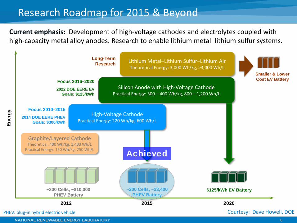
Research Roadmap for 2015 & Beyond Current emphasis: Development of high-voltage cathodes and electrolytes coupled with high-capacity metal alloy anodes. Research to enable lithium metal–lithium sulfur systems.
Lithium Metal–Lithium Sulfur–Lithium Air Theoretical Energy: 3,000 Wh/kg, >3,000 Wh/L
Silicon Anode with High-Voltage Cathode Practical Energy: 300 – 400 Wh/kg, 800 – 1,200 Wh/L
Smaller & Lower Cost EV Battery
High-Voltage Cathode Practical Energy: 220 Wh/kg, 600 Wh/L
Achieved
Long-Term Research
Focus 2016–2020 2022 DOE EERE EV
Goals: $125/kWh
Focus 2010–2015 2014 DOE EERE PHEV
Goals: $300/kWh
~300 Cells, ~$10,000 PHEV Battery
~200 Cells, ~$3,400 PHEV Battery
$125/kWh EV Battery
2012 2015 2020
Graphite/Layered Cathode Theoretical: 400 Wh/kg, 1,400 Wh/L
Practical Energy: 150 Wh/kg, 250 Wh/L
Ener
gy
Courtesy: Dave Howell, DOE PHEV: plug-in hybrid electric vehicle
9
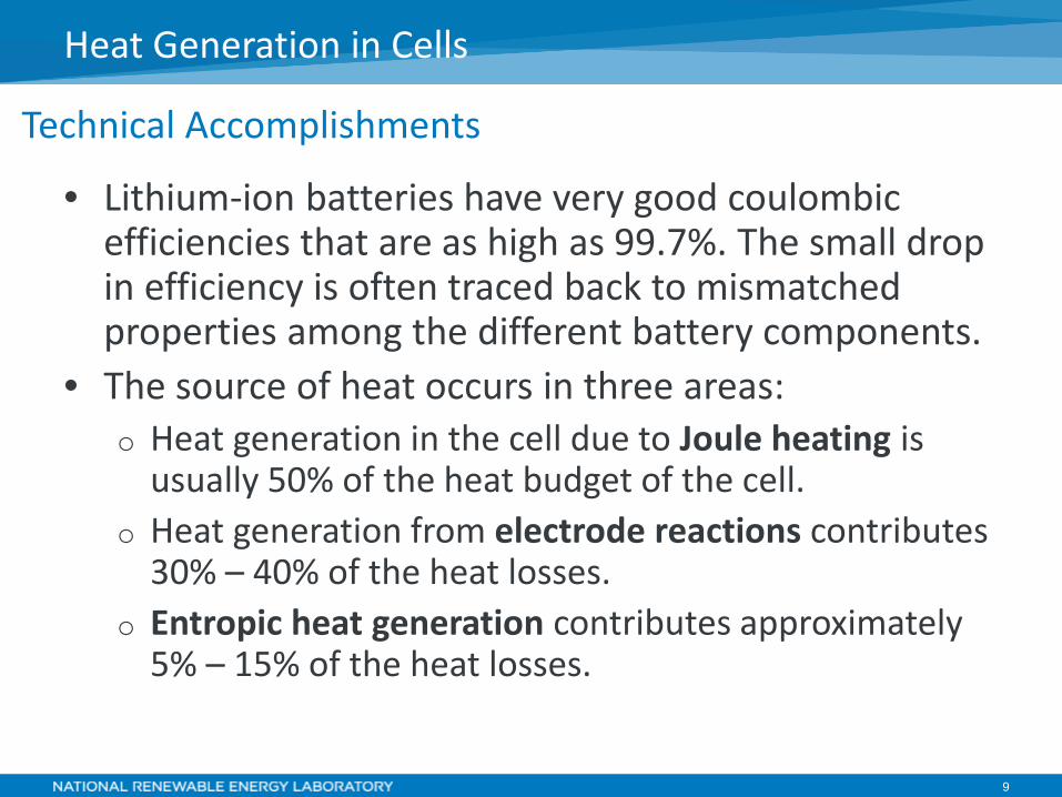
• Lithium-ion batteries have very good coulombic efficiencies that are as high as 99.7%. The small drop in efficiency is often traced back to mismatched properties among the different battery components.
• The source of heat occurs in three areas: o Heat generation in the cell due to Joule heating is
usually 50% of the heat budget of the cell. o Heat generation from electrode reactions contributes
30% – 40% of the heat losses. o Entropic heat generation contributes approximately
5% – 15% of the heat losses.
Technical Accomplishments
Heat Generation in Cells
10
Technical Accomplishments
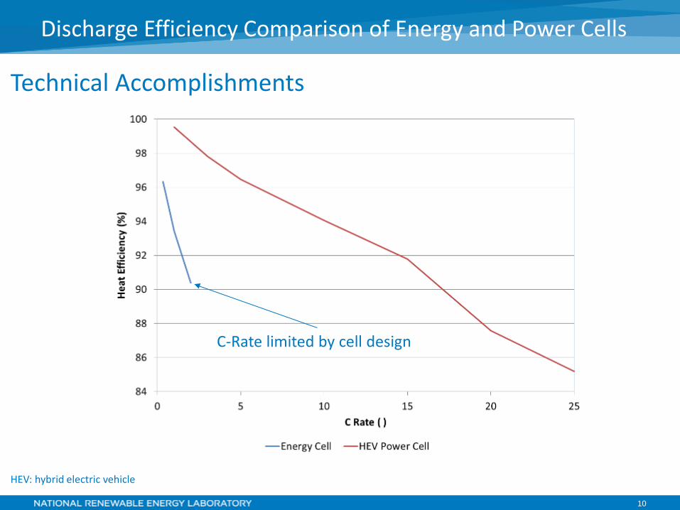
Discharge Efficiency Comparison of Energy and Power Cells
C-Rate limited by cell design
HEV: hybrid electric vehicle

11
Technical Accomplishments
Solid electrolyte cells have lower efficiencies even when used at higher temperatures.
Efficiency Limitations Associated with Advanced Chemistries
12
Technical Accomplishments
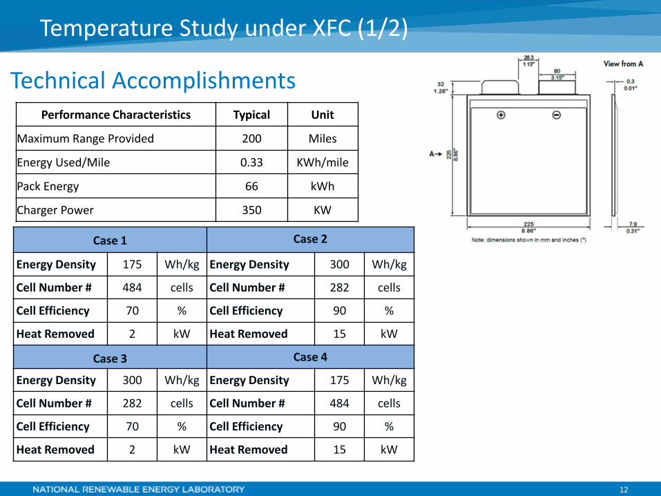
Temperature Study under XFC (1/2)
Performance Characteristics Typical Unit
Maximum Range Provided 200 Miles
Energy Used/Mile 0.33 KWh/mile
Pack Energy 66 kWh
Charger Power 350 KW
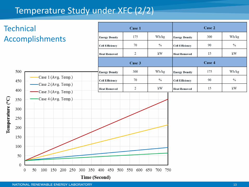
Case 1 Case 2
Energy Density 175 Wh/kg Energy Density 300 Wh/kg
Cell Number # 484 cells Cell Number # 282 cells
Cell Efficiency 70 % Cell Efficiency 90 %
Heat Removed 2 kW Heat Removed 15 kW
Case 3 Case 4
Energy Density 300 Wh/kg Energy Density 175 Wh/kg
Cell Number # 282 cells Cell Number # 484 cells
Cell Efficiency 70 % Cell Efficiency 90 %
Heat Removed 2 kW Heat Removed 15 kW
13
Technical Accomplishments
Temperature Study under XFC (2/2)
14
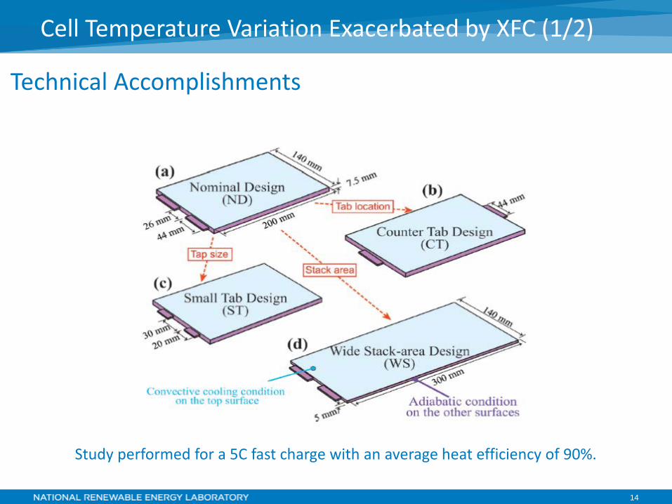
Cell Temperature Variation Exacerbated by XFC (1/2)
Technical Accomplishments
Study performed for a 5C fast charge with an average heat efficiency of 90%.
15
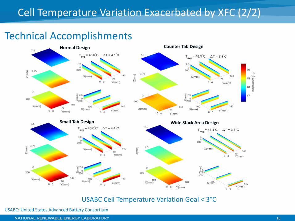
Cell Temperature Variation Exacerbated by XFC (2/2)
Technical Accomplishments
USABC Cell Temperature Variation Goal < 3°C USABC: United States Advanced Battery Consortium
Normal Design
Wide Stack Area Design Small Tab Design
Counter Tab Design
16
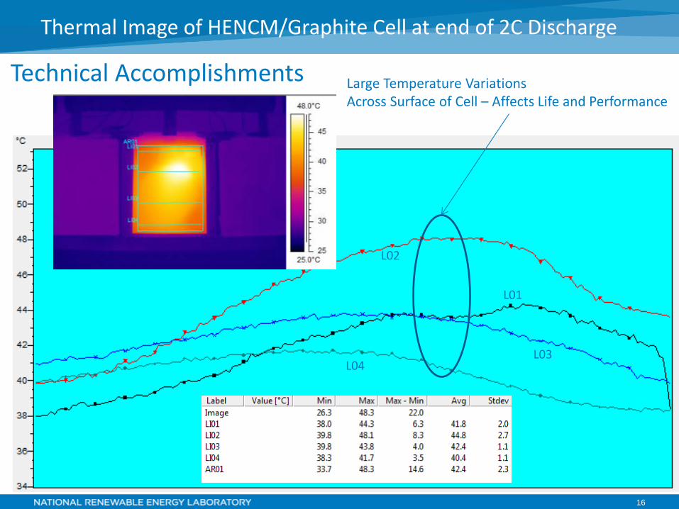
Technical Accomplishments
Endotherm atypical of LTO anode cells
Thermal Image of HENCM/Graphite Cell at end of 2C Discharge
L04
L01
L03
L02
Large Temperature Variations Across Surface of Cell – Affects Life and Performance
17
• Increasing the amount of carbon black or other conductive material in the cathode and anode.
• Increasing the thickness of the current collectors • Incorporate low-temperature phase change material
within the cell to absorb heat where it is generated. Is it feasible to modify the cell with an electrochemically inert material?
• Continuous current collectors have a more optimal heat conductive path. Do we eliminate stacked cells from consideration? Cylindrical cells have a low packing density; do we look at oval cells in a prismatic package? Is there an optimal battery form factor for thermal design?
Cell Design Thermal Considerations
18
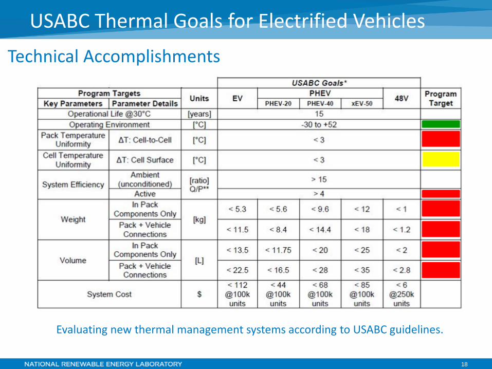
USABC Thermal Goals for Electrified Vehicles Technical Accomplishments
Evaluating new thermal management systems according to USABC guidelines.
19
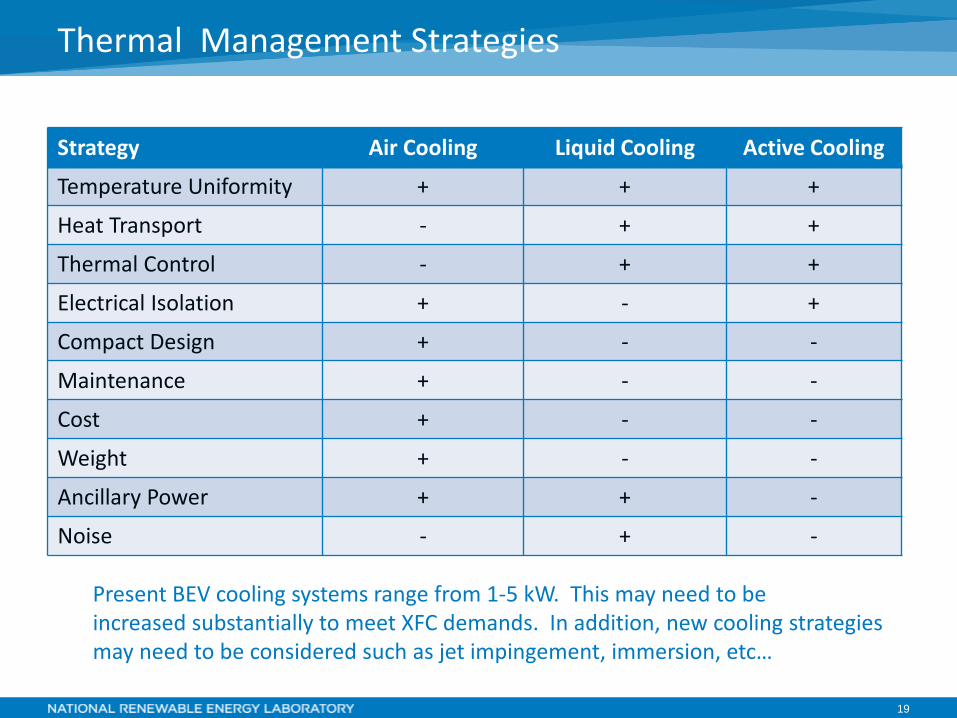
Thermal Management Strategies
Strategy Air Cooling Liquid Cooling Active Cooling
Temperature Uniformity + + +
Heat Transport - + +
Thermal Control - + +
Electrical Isolation + - +
Compact Design + - -
Maintenance + - -
Cost + - -
Weight + - -
Ancillary Power + + -
Noise - + -
Present BEV cooling systems range from 1-5 kW. This may need to be increased substantially to meet XFC demands. In addition, new cooling strategies may need to be considered such as jet impingement, immersion, etc…
20
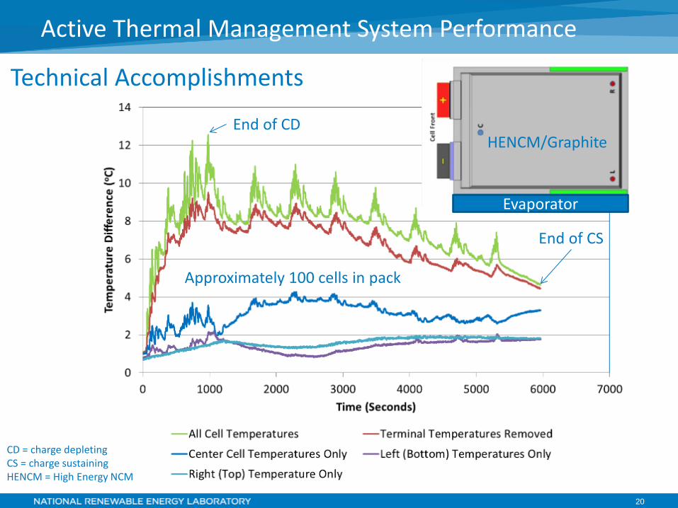
Active Thermal Management System Performance
End of CD
Evaporator
Approximately 100 cells in pack
CD = charge depleting CS = charge sustaining HENCM = High Energy NCM
Technical Accomplishments
HENCM/Graphite
End of CS
21
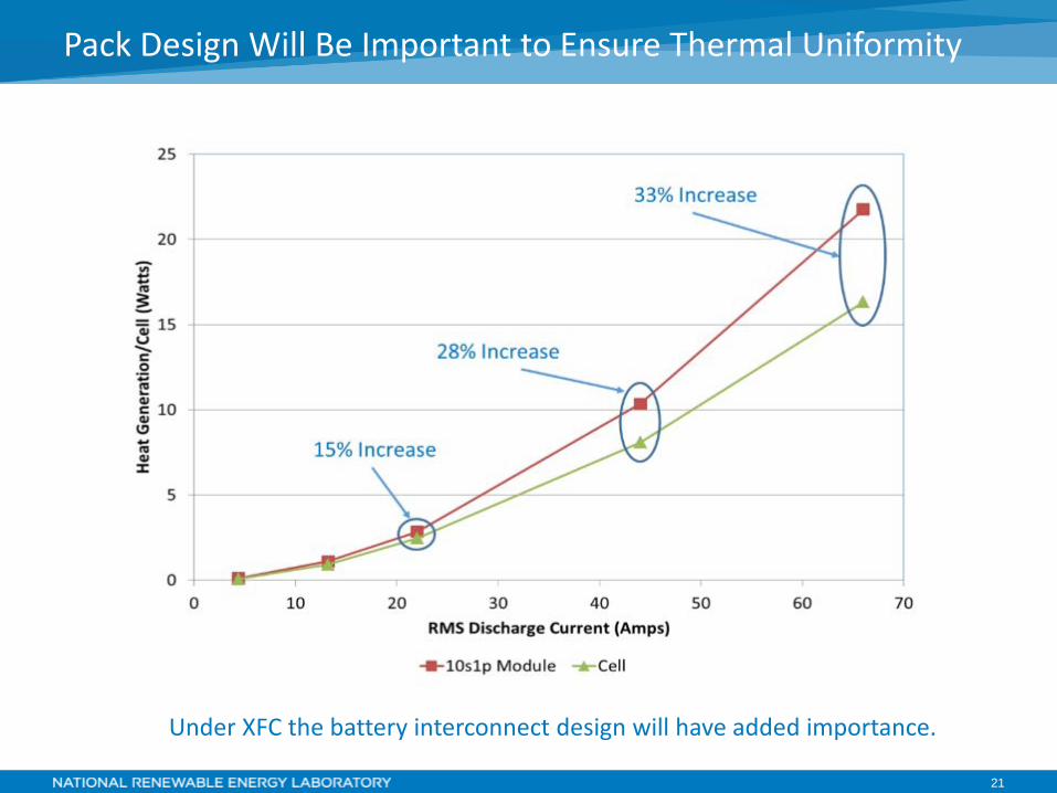
Pack Design Will Be Important to Ensure Thermal Uniformity
Under XFC the battery interconnect design will have added importance.
22
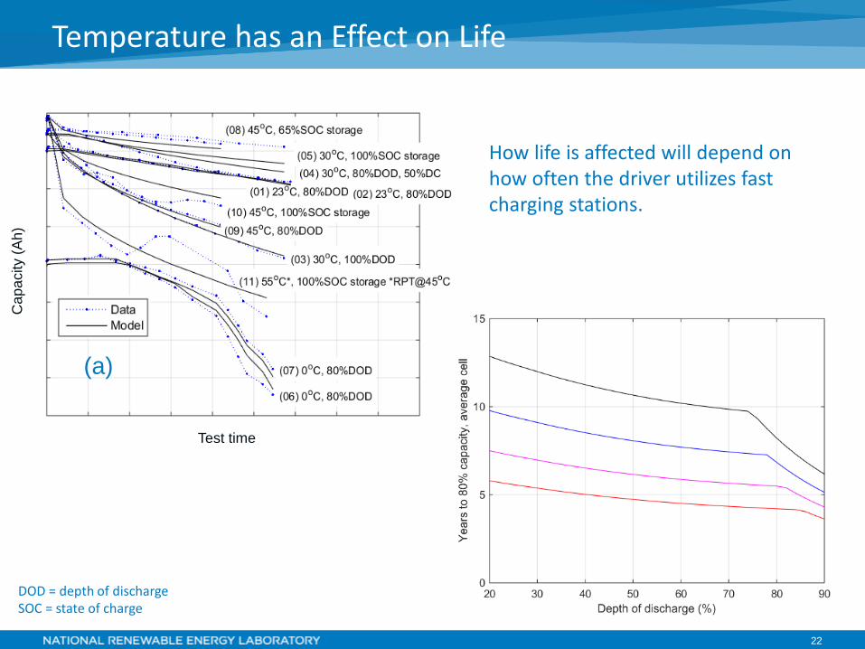
Temperature has an Effect on Life C
apac
ity (A
h)
Test time
(a)
How life is affected will depend on how often the driver utilizes fast charging stations.
DOD = depth of discharge SOC = state of charge
23
• Not reviewed at the 2016 AMR.
Response to Previous Year Reviewers’ Comments
24
• National Labs o 1Argonne National Laboratory (ANL) o 2Idaho National Laboratory (INL) o 3National Renewable Energy Laboratory (NREL)
• Received input from stakeholders o Vehicle original equipment manufacturers (OEMs) o Battery manufacturers o Utilities
• Team o Shabbir Ahmed,1 Ira Bloom,1 Andrew Burnham,1 Barney Carlson,2
Fernando Dias,2 Eric J. Dufek,2 Keith Hardy,1 Andrew N. Jansen,1 Matthew Keyser,3 Cory Kreuzer,3 Anthony Markel,3 Andrew Meintz,3 Christopher Michelbacher,2 Manish Mohanpurkar,2 Paul A. Nelson,1 Ahmad Pesaran,3 David C. Robertson,1 Don Scoffield,2 Matthew Shirk,2 Thomas Stephens,1 Tanvir Tanim,2 Ram Vijayagopal,1 and Jiucai Zhang3
Collaborations
25
• Robust battery thermal management will be required to make XFC a reality – even with high-power cells, an oversized battery thermal management system will needed.
• The size of the battery thermal management system will have to increase from today’s BEV average size of 1–5 kW to around 15–25 kW.
• The heat efficiency of high energy density cells will need to improve by 10%–20% at high rates of charge.
• New thermal management strategies like jet impingement or immersion of the battery in a dielectric fluid may need to be investigated to keep the battery below the operational maximum temperature limit.
• The cell-to-cell imbalance due to EFC will affect the longevity and cycle life cost of the cells. New passive and/or active battery management systems will need to be investigated to ensure that the batteries meet the OEM’s warranty obligations.
• Cell design will have an impact on the temperature variation within the cell and the temperature imbalance within the pack.
• The mean average temperature of the battery directly affects the cycle life of the battery. High EFC utilization by the driver will have a strong influence on this metric.
• Additional cooling at the EFC station may be required to ensure a complete charge of the battery pack.
Summary


![Key Word: Fascism: an extreme form of nationalism that emphasizes conformity [sameness] and militarism, usually with a dictator in charge who has](https://img.pdfslide.us/doc/110x75/5a4d1b837f8b9ab0599bbe0b/key-word-fascism-an-extreme-form-of-nationalism-that-emphasizes-conformity-sameness.jpg)