Embed Size (px)
Citation preview

Thermal Imaging
By
Colin Pearson
Head of Condition Monitoring – BSRIA
In Association with
Anderson Mechanical Services
Loughgall,
Armagh
BT61 8HZ
www.andersonmechanical.net
Email: [email protected]

My background
Head of Condition Monitoring at Research and Specialist Consultants, BSRIA.
PCN Level III thermographer
Chairman of the UK Thermography Association
Fellow of BINDT
Member of CIBSE
Associate Member Institute of Acoustics
14 years experience in building thermography
5 years experience in acoustic testing
Chairman Thermography Training and Certification Working Group
BSI and ISO CM & NDT committees.
10 years in research & consultancy for farm buildings
BSc Environmental Engineering
5 years with mechanical and electrical contractor
4 years with lighting manufacturer

Today’s Presentation
Current Building Regulations
Testing vs. Assured Design
Thermal Imaging Basics
Buildings
Benefits
Acoustic Testing Basics
Benefits
Training and certification
The future

Current Building Standards (Regulations)
The Building Control Act 2007 Ireland (Building Standards)
Technical Guidance Documents (Approved Documents)
Parts A to M (L: Conservation of Fuel & Energy, E: Sound)
Specifies the minimum acceptable standards
No testing specified
Are these providing the right quality of buildings?

Testing vs. Assured Design
No matter how good the design and the Building Inspector, there is no way to be sure of thermal insulation or noise isolation without testing!

Pre-Completion Testing
Thermal insulation problems don’t show until it gets cold
Acoustic problems don’t show until the neighbours are noisy
The only way to be sure is to test!
Testing provides quality assurance
Thermal Imaging - Basics
Infrared
Material properties
Imaging systems
Benefits
Common faults
Survey method
Understanding results

Infrared radiation
Discovered in 1800 by William Herschel
“There is a heating effect from solar radiation beyond the red zone of the visible spectrum”
Detection improved by thermoelectric thermometer (Nobili – 1830)
The radiated energy is due to molecular vibration (Maxwell theory of EM radiation - 1873)
Intensity of radiation depends on temperature (Boltzman) = T4 (Stefan’s Law) = 5.6686 x 10 –8 Wm-2 K-4
All objects above absolute zero emit IR
Wavelength of peak radiation depends on temperature (Wien’s law)
Quantum Hypothesis (Planck – 1906)

UV
AM radio
TV & radioTV & radio
Microwaves
Infrared
VisibleX-rays
1m 10m 100m 1km100mm10mm1mm10µm 100µm.1nm 1nm 10nm 100nm 1µm
Wavelength
100nm 1µm 10µm 100µm 1mm
InfraredVisible
SW LW
The infrared spectrum

Important material properties
Emittance
Transmittance
Reflectance
Background temperature
Size
Distance
Thermal capacity

Emittance, reflectance & transmittance
r + a +t =1

Imaging systems
1960s-70s systems

Imaging systems
1970s systems

Thermal imaging cameras

Imaging systems
21st Century systems
Low noise images - 80 mK thermal sensitivity
High definition images –640x480 pixels resolution, 307,200 picture elements
Full speed 50 Hz images
High usability with voice and PDA interfaces
Sophisticated analysis software

Benefits of thermal imaging
Quick inspection
Results clearly shown in pictures
Shows precise location of fault
Shows severity of fault
Shows compliance with regulations
Improves quality of products

Building fabric thermography

Building fabric thermography

Defects
Cold bridging
Missing insulation
Air leakage
Slipped insulation

Gaps in insulation
16.0°C
27.0°C
16
18
20
22
24
26

insulation gaps - walls

Thermography locates air leakage
25.5°C
31.0°C
26
27
28
29
30
31
behind plasterboard

Gaps in insulation
-4.0°C
5.0°C
-4
-2
0
2
4

Cold bridges - steelwork
21.2°C
26.5°C
22
23
24
25
26SP01
SP02 SP03
SP04

Cold Bridge location 2
30.0°C
36.0°C
30
32
34
36

Air leakagelocation
30.0°C
36.0°C
30
32
34
36

19.118.4
15.8
3.9
2.8
0.2
0.000
2
4
6
8
10
12
14
16
18
20
0 50 100 150 200 250 300
Distance, mm
Tem
pera
ture
, °C
Block Brick
Insula
tion
Cavity
Air
Air
Pla
ster
Good structure U value 0.35

18.2
17.1
- 6.9
- 5
0.8+ 0.000
2
4
6
8
10
12
14
16
18
20
0 50 100 150 200 250 300
Distance, mm
Tem
pera
ture
, °C
Block Brick
Mis
sin
g Insu
latio
n
Air
Air
Pla
ster
Poor structure U value 0.85

16.3
14.5
- 11.2
6.4
0.8+ 0.000
2
4
6
8
10
12
14
16
18
20
0 50 100 150 200 250 300
Distance, mm
Tem
pera
ture
, °C
Block
Brick
Mis
sin
g Insu
latio
n
Air
Air
Pla
ster
Mortar in poor structure U value 1.41
Mortar
Dewpoint of 20°C air at 80% rh = 16.5°C

Mortar in poor structure U value 1.41
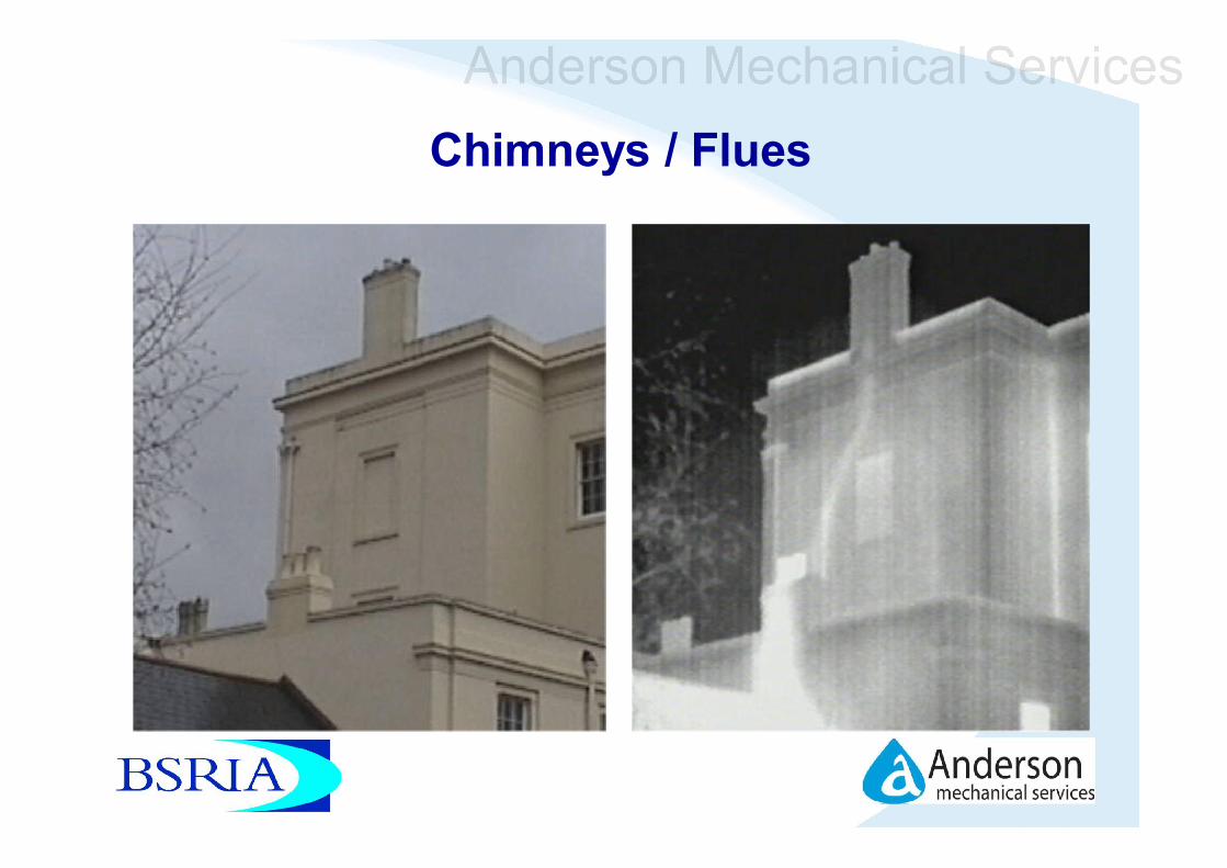
Chimneys / Flues

Case study 1
retail building, 130x75 metres and 6-9 m high
interface detail left a 73mm strip uninsulated
=30 square metres of cladding with a U value of 3.5W/m²K instead of 0.35W/m²K.
would require an extra 2kW of heating
nearly 8000 kWh a year extra heating
cost of over €1000 a year
generating nearly 4000kg of additional CO2.

Extract from the thermographic report - before
Note: this is inside of building but outside was warmer so the poorly insulated areas show up as warm

Building fabric thermography
Construction defects

Building fabric thermography
Construction defects
Remedial action

Building Regulations Part L2 (2002)
“The person responsible for achieving compliance should (if suitably qualified) provide a certificate or declaration that the provisions meet the requirements of Part L2(a);
or they should obtain a certificate or declaration to that effect from a suitably qualified person. Such certificates or declarations would state:
a) that appropriate design details and building techniques have been used or
b) that infra-red thermography inspections have shown that the insulation is reasonably continuous over the whole visible envelope”

But are the buildings acceptable?
Normally rely on skill and experience of thermographer
No guidance on what is acceptable
Standards and Guides do not set criteria
Proposals in England and Wales for certification by a competent thermographer

What needs to change?
Certification of competence
Define acceptable limits
Show how to prove compliance

Certification of competence
PCN Level 2 Civil
Possible ‘House Thermographer’ certification

How do you show compliance?
Show thermal anomalies
Differentiate between real thermal anomalies and confounding factors
such as localised differences in air movement, reflection and emissivity
Quantify affected areas and their severity
State whether the anomalies and the building thermal insulation are acceptable

Approach
Select critical temperature factor
Select acceptable defect area limit
Measure surface temperature difference caused by each anomaly
Measure or estimate area of the defects
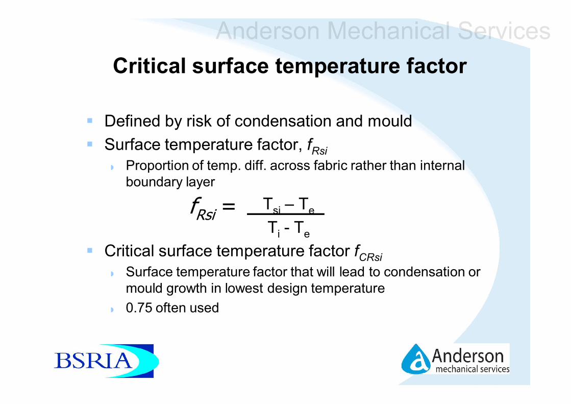
Critical surface temperature factor
Defined by risk of condensation and mould
Surface temperature factor, fRsi
Proportion of temp. diff. across fabric rather than internal boundary layer
Tsi – Te
Ti - Te
Critical surface temperature factor fCRsi
Surface temperature factor that will lead to condensation or mould growth in lowest design temperature
0.75 often used
fRsi =

Allowable area
Must maintain high standards without alienating construction industry by failing too many buildings
0.1% is suggested as suitable for large commercial and retail buildings
This leads to about one failure in six

Surface temperature and area measurement
Temperature measurement is common feature of a thermographic survey
Area measurement is often a feature of analysis software requiring:
Object distance
Angular field of view
Setting threshold temperature in software
Pixel counting
Computation of area below threshold temperature

Conditions and equipment
Suitable conditions, equipment and repeatable method required
Follow existing standard – eg BS EN 13187:1999, Thermal Performance of
buildings – Qualitative detection of thermal properties in building envelopes – Infrared method (ISO 6781:1983 modified)

Method
Internal survey usually best
Requires image of every anomaly
image square to any features of the wall or roof.
viewing angle perpendicular to surface imaged
interfering sources of infrared radiation such as lights, heat emitters, electric conductors, reflective elements minimised
Requires calculation of building surface area

Analysis
Adjust each image for distance, background temp & emissivity
Place area analysis tool to enclose anomaly
Set threshold temp. for area according to internal & external temp.
Use pixel counting tool and calculation from image parameters to find area below threshold
Repeat for all anomalies
Use summary table to add all areas below threshold

Limitations
This method may not be suitable for:
Heavyweight structures, particularly where the main insulating element is near the outside surface
Buildings where much of the internal surface is obscured, eg by false ceilings.

Energy efficiency survey
Heat loss through structure can be shown by surface temperature
Calculated from temperature difference across boundary layer
Depends on constant boundary layer resistance and known internal temperature
Example

Impact of introducing testing
Projection, because we don’t have it yet
Improved average thermal performance about 200kWh/yr for a house, or 37kg CO2 emissions
Extra cost of construction €0 just applying best practice
Extra cost of testing €15/house based on 1/10 sample
Extra cost of remedial action

Conclusions
There is a practical, repeatable semi-quantitative method of assessing thermal insulation performance
It is being used by thermographers in England and other countries worldwide
It may be used to show compliance with Building Regulations
Infrared cameras are being produced with software to identify defective areas

Contact
Anderson Mechanical Services
77B Main Street
Loughgall,
Armagh
BT61 8HZ
www.andersonmechanical.net
Email: [email protected]
Tel: +44 28 3889 1320 (NI)
Tel: 048 3889 1320 (ROI)
![THERMAL IMAGING GUIDEBOOK - flirmedia.com · THERMAL IMAGING GUIDEBOOK FOR FACILITIES MAINTENANCE. Table of Contents: 1] How thermal imaging cameras work 2 ... and water intrusion](https://img.pdfslide.us/doc/110x75/5b47a1fc7f8b9a252e8b889b/thermal-imaging-guidebook-thermal-imaging-guidebook-for-facilities-maintenance.jpg)