Embed Size (px)
Citation preview
Aurora’s Technological and Research Institute Thermal Lab
Department of Mechanical 1
THERMAL ENGINEERING
LAB MANUAL
B. Tech III Year - I Semester
DEPARTMENT OF
MECHANICAL ENGINEERING
Aurora’s Technological And Research Institute
Parvathapur, Uppal, Hyderabad-98.
NAME : ______________________________________
ROLL NO : ______________________________________
BRANCH : _______________________________________
Aurora’s Technological and Research Institute Thermal Lab
Department of Mechanical 2
List of Experiments
1. I.C Engines Valve/Port Timing Diagrams
2. I.C.Engines Performance Test (4 – Stroke Diesel Engines)
3. I.C. Engines Performance Test on 2-stroke Petrol
4. Evaluation of Engine friction by conducting Morse test on 4-Stroke
Multi cylinder Petrol Engine
5. Evaluate of engine friction by conducting motoring/retardation test on
4 stroke diesel Engine.
6. Heat balance on IC Engines.
7. Performance Test on Reciprocating Air Compressor Unit.
8. Study of Boilers.
9. Determination of Air fuel ratio and volumetric efficiency on IC engine
10. Determination of Economical Speed Test for Fixed Load on 4-stroke
engine
Aurora’s Technological and Research Institute Thermal Lab
Department of Mechanical 3
EXPERIMENT-1
I.C ENGINES VALVE/PORT TIMING DIAGRAMS
1) FOUR – STROKE CYCLE DIESEL ENGINE:
It is also known as compression ignition engine because the ignition takes place due
to the heat produced in the engine cylinder at the end of compression stroke. The four
strokes of a diesel engine sucking pure air are described below:
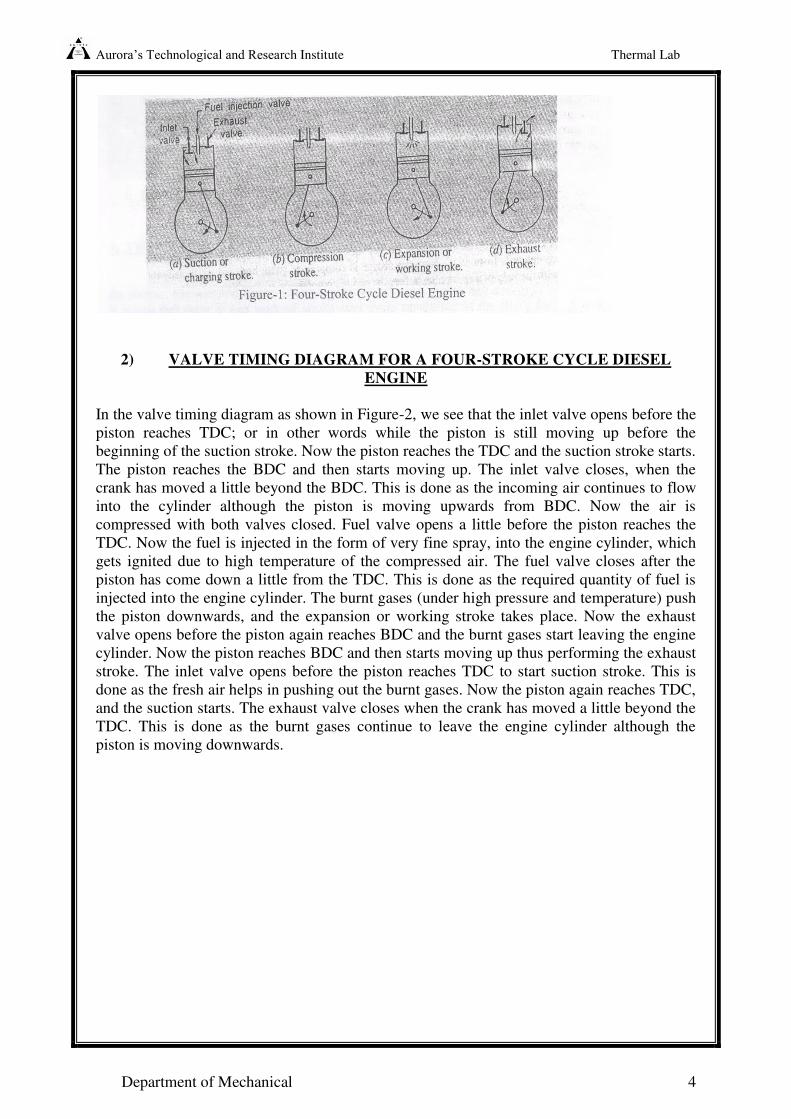
1. Suction or charging stroke: In this stroke, the inlet valve opens and pure air is sucked
into the cylinder as the piston moves down wards from the top dead center (TDC). It
continues till the piston reaches its bottom dead center (BDC) as shown in the Figure
1 (a).
2. Compression stroke: In this stroke, both valves are closed on the air is compressed as
the piston moves upwards from BDC to TDC. As a result compression, pressure and
temperature of the air increases considerably (the actual value depends upon the
compression ratio). This completes one revolution of the crank shaft. The
compression stroke is shown in Figure 1 (b).
3. Expansion or working stroke: Shortly before the piston reaches the TDC (during the
compression stroke), fuel oil is injected in the form of very fine spray into the engine
cylinder, through the nozzle, known as fuel injection valve. At this moment,
temperature of the compressed air is sufficiently high to ignite the fuel. It suddenly
increases the pressure and temperature of the products of combustion. The fuel oil is
continuously injected for a fraction of the revolution. The fuel oil is assumed to be
burnt at constant pressure. Due to increased pressure, the piston is pushed down with
a great force. The hot burnt gases expand due to high speed of the piston. During this
expansion, some of the heat energy is transformed into mechanical work. It may be
noted that during the working stroke, both the valves are closed and the (Piston moves
from T.D.C to B.D.C (as shown in figure 1 (c) )
4. Exhaust stroke: In this stroke, the exhaust valve is open as the pistion moves from
BDC to TDC. This movement of the piston pushes out the products of combustion
from the engine cylinder through the exhaust valve into the atmosphere. This
completes the cycle and the engine cylinder is ready to suck the fresh air again. (as
shown in Figure 1 (d) ).
Aurora’s Technological and Research Institute Thermal Lab
Department of Mechanical 4
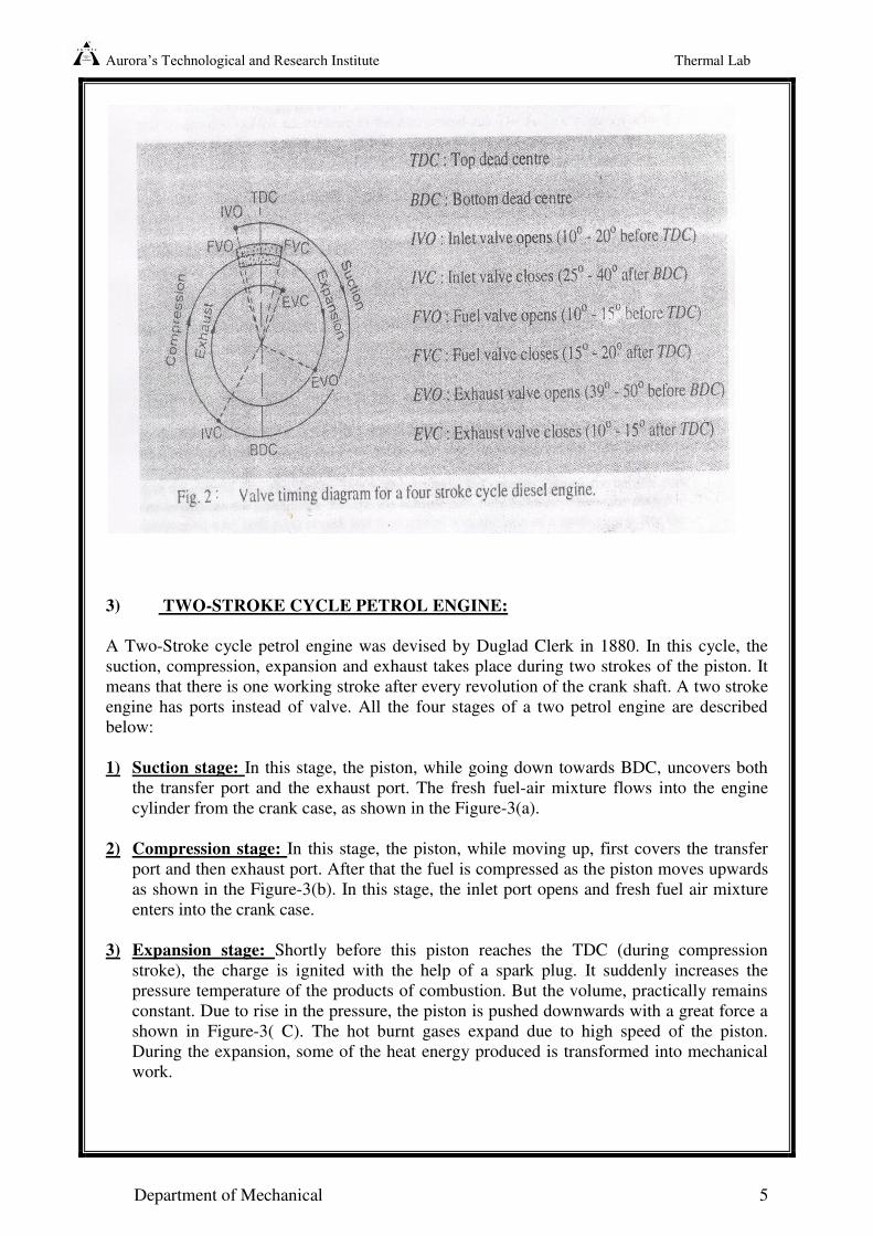
2) VALVE TIMING DIAGRAM FOR A FOUR-STROKE CYCLE DIESEL
ENGINE
In the valve timing diagram as shown in Figure-2, we see that the inlet valve opens before the
piston reaches TDC; or in other words while the piston is still moving up before the
beginning of the suction stroke. Now the piston reaches the TDC and the suction stroke starts.
The piston reaches the BDC and then starts moving up. The inlet valve closes, when the
crank has moved a little beyond the BDC. This is done as the incoming air continues to flow
into the cylinder although the piston is moving upwards from BDC. Now the air is
compressed with both valves closed. Fuel valve opens a little before the piston reaches the
TDC. Now the fuel is injected in the form of very fine spray, into the engine cylinder, which
gets ignited due to high temperature of the compressed air. The fuel valve closes after the
piston has come down a little from the TDC. This is done as the required quantity of fuel is
injected into the engine cylinder. The burnt gases (under high pressure and temperature) push
the piston downwards, and the expansion or working stroke takes place. Now the exhaust
valve opens before the piston again reaches BDC and the burnt gases start leaving the engine
cylinder. Now the piston reaches BDC and then starts moving up thus performing the exhaust
stroke. The inlet valve opens before the piston reaches TDC to start suction stroke. This is
done as the fresh air helps in pushing out the burnt gases. Now the piston again reaches TDC,
and the suction starts. The exhaust valve closes when the crank has moved a little beyond the
TDC. This is done as the burnt gases continue to leave the engine cylinder although the
piston is moving downwards.
Aurora’s Technological and Research Institute Thermal Lab
Department of Mechanical 5
3) TWO-STROKE CYCLE PETROL ENGINE:
A Two-Stroke cycle petrol engine was devised by Duglad Clerk in 1880. In this cycle, the
suction, compression, expansion and exhaust takes place during two strokes of the piston. It
means that there is one working stroke after every revolution of the crank shaft. A two stroke
engine has ports instead of valve. All the four stages of a two petrol engine are described
below:
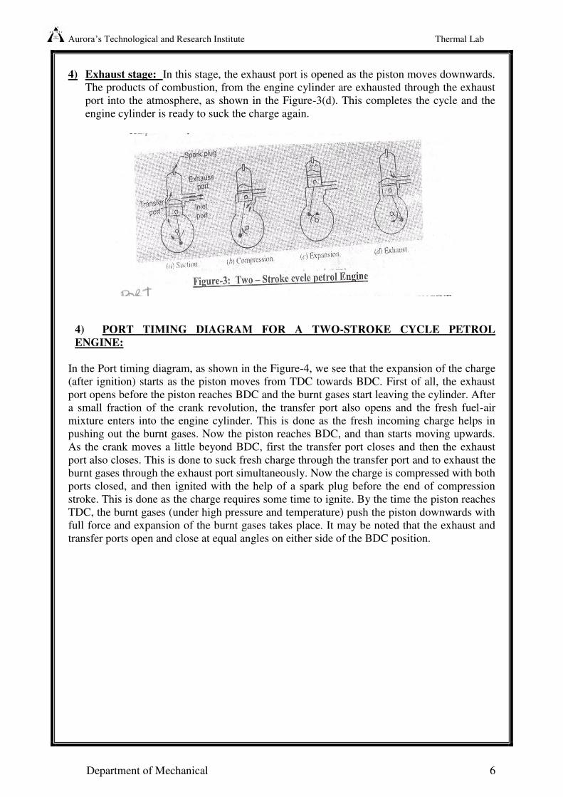
1) Suction stage: In this stage, the piston, while going down towards BDC, uncovers both
the transfer port and the exhaust port. The fresh fuel-air mixture flows into the engine
cylinder from the crank case, as shown in the Figure-3(a).
2) Compression stage: In this stage, the piston, while moving up, first covers the transfer
port and then exhaust port. After that the fuel is compressed as the piston moves upwards
as shown in the Figure-3(b). In this stage, the inlet port opens and fresh fuel air mixture
enters into the crank case.
3) Expansion stage: Shortly before this piston reaches the TDC (during compression
stroke), the charge is ignited with the help of a spark plug. It suddenly increases the
pressure temperature of the products of combustion. But the volume, practically remains
constant. Due to rise in the pressure, the piston is pushed downwards with a great force a
shown in Figure-3( C). The hot burnt gases expand due to high speed of the piston.
During the expansion, some of the heat energy produced is transformed into mechanical
work.
Aurora’s Technological and Research Institute Thermal Lab
Department of Mechanical 6
4) Exhaust stage: In this stage, the exhaust port is opened as the piston moves downwards.
The products of combustion, from the engine cylinder are exhausted through the exhaust
port into the atmosphere, as shown in the Figure-3(d). This completes the cycle and the
engine cylinder is ready to suck the charge again.
4) PORT TIMING DIAGRAM FOR A TWO-STROKE CYCLE PETROL
ENGINE:
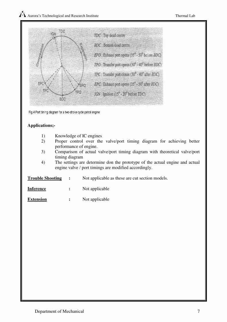
In the Port timing diagram, as shown in the Figure-4, we see that the expansion of the charge
(after ignition) starts as the piston moves from TDC towards BDC. First of all, the exhaust
port opens before the piston reaches BDC and the burnt gases start leaving the cylinder. After
a small fraction of the crank revolution, the transfer port also opens and the fresh fuel-air
mixture enters into the engine cylinder. This is done as the fresh incoming charge helps in
pushing out the burnt gases. Now the piston reaches BDC, and than starts moving upwards.
As the crank moves a little beyond BDC, first the transfer port closes and then the exhaust
port also closes. This is done to suck fresh charge through the transfer port and to exhaust the
burnt gases through the exhaust port simultaneously. Now the charge is compressed with both
ports closed, and then ignited with the help of a spark plug before the end of compression
stroke. This is done as the charge requires some time to ignite. By the time the piston reaches
TDC, the burnt gases (under high pressure and temperature) push the piston downwards with
full force and expansion of the burnt gases takes place. It may be noted that the exhaust and
transfer ports open and close at equal angles on either side of the BDC position.
Aurora’s Technological and Research Institute Thermal Lab
Department of Mechanical 7
Applications;-
1) Knowledge of IC engines
2) Proper control over the valve/port timing diagram for achieving better
performance of engine.
3) Comparison of actual valve/port timing diagram with theoretical valve/port
timing diagram
4) The settings are determine don the prototype of the actual engine and actual
engine valve / port timings are modified accordingly.
Trouble Shooting : Not applicable as these are cut section models.
Inference : Not applicable
Extension : Not applicable
Aurora’s Technological and Research Institute Thermal Lab
Department of Mechanical 8
EXPERIMENT-2
I.C.ENGINES PERFORMANCE TEST (4 – STROKE DIESEL ENGINES)
Aim:-
To conduct load test on single cylinder, vertical, water –cooled diesel engine and hence to
determine frictional power and draw the performance characteristic curves.
Apparatus:-
Single cylinder diesel engine test rig coupled with rope brake dynamometer, stop watch.
Engine Specification:-
TYPE : 4-STROKE DIESEL ENGINE
( water cooled)
MAKE : KIRLOSKAR
BORE : 85 mm
STROKE : 110 mm
SPEED : 1500 rpm
OUTPUT : 5HP
COMPRESSION RATIO : 16.5 : 1
BRAKE DRUM RADIUS : 0.185 m
ORFICE DIAMETER : 15 mm
SPECIFIC GRAVITY OF
H.S.D.OIL : 0.85 gm/ml
CALORIFIC VALUE : 10,000 K cal/kg
Description:-
The water-cooled single cylinder diesel engine is coupled with a rope brake dynamometer.
Separate cooling lines are provided for the drum and the engine. Thermocouples are arranged
for sensing the temperature of cooling water consisting of fuel tank mounted on stand,
burette with 3-way cock arrangement is provided.
Aurora’s Technological and Research Institute Thermal Lab
Department of Mechanical 9
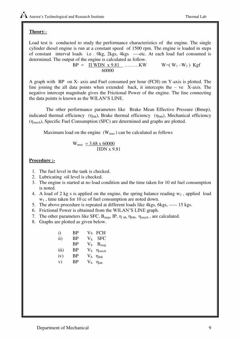
Theory:-
Load test is conducted to study the performance characteristics of the engine. The single
cylinder diesel engine is run at a constant speed of 1500 rpm. The engine is loaded in steps
of constant interval loads i.e . 0kg, 2kgs, 4kgs ----etc. At each load fuel consumed is
determined. The output of the engine is calculated as follow.
BP = П WDN x 9.81 ………KW W=( W1 –W2 ) Kgf
60000
A graph with BP on X- axis and Fuel consumed per hour (FCH) on Y-axis is plotted. The
line joining the all data points when extended back, it intercepts the – ve X-axis. The
negative intercept magnitude gives the Frictional Power of the engine. The line connecting
the data points is known as the WILAN’S LINE.
The other performance parameters like Brake Mean Effective Pressure (Bmep),
indicated thermal efficiency (ith), Brake thermal efficiency (bth), Mechanical efficiency
(mech), Specific Fuel Consumption (SFC) are determined and graphs are plotted.
Maximum load on the engine (Wmax ) can be calculated as follows
Wmax = 3.68 x 60000
ПDN x 9.81
Procedure :-
1. The fuel level in the tank is checked.
2. Lubricating oil level is checked.
3. The engine is started at no load condition and the time taken for 10 ml fuel consumption
is noted.
4. A load of 2 kg s is applied on the engine, the spring balance reading w2 , applied load
w1 , time taken for 10 cc of fuel consumption are noted down.
5. The above procedure is repeated at different loads like 4kgs, 6kgs, ----- 15 kgs.
6. Frictional Power is obtained from the WILAN’S LINE graph. 7. The other parameters like SFC, Bmep, IP, ith, bth, mech , are calculated.
8. Graphs are plotted as given below.
i) BP Vs FCH
ii) BP VS SFC
BP VS Bmep
iii) BP VS mech
iv) BP VS bth
v) BP VS ith
Aurora’s Technological and Research Institute Thermal Lab
Department of Mechanical 10
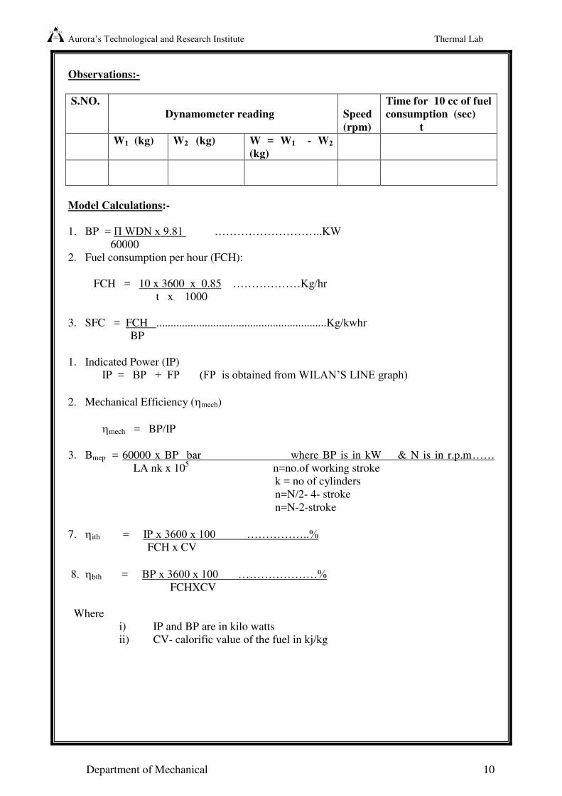
Observations:-
S.NO.
Dynamometer reading
Speed
(rpm)
Time for 10 cc of fuel
consumption (sec)
t
W1 (kg) W2 (kg) W = W1 - W2
(kg)
Model Calculations:-
1. BP = П WDN x 9.81 ………………………..KW 60000
2. Fuel consumption per hour (FCH):
FCH = 10 x 3600 x 0.85 ………………Kg/hr t x 1000
3. SFC = FCH ............................................................Kg/kwhr
BP
1. Indicated Power (IP)
IP = BP + FP (FP is obtained from WILAN’S LINE graph)
2. Mechanical Efficiency (mech)
mech = BP/IP
3. Bmep = 60000 x BP bar where BP is in kW & N is in r.p.m…… LA nk x 10
5 n=no.of working stroke
k = no of cylinders
n=N/2- 4- stroke
n=N-2-stroke
7. ith = IP x 3600 x 100 ……………..%
FCH x CV
8. bth = BP x 3600 x 100 …………………%
FCHXCV
Where
i) IP and BP are in kilo watts
ii) CV- calorific value of the fuel in kj/kg
Aurora’s Technological and Research Institute Thermal Lab
Department of Mechanical 11
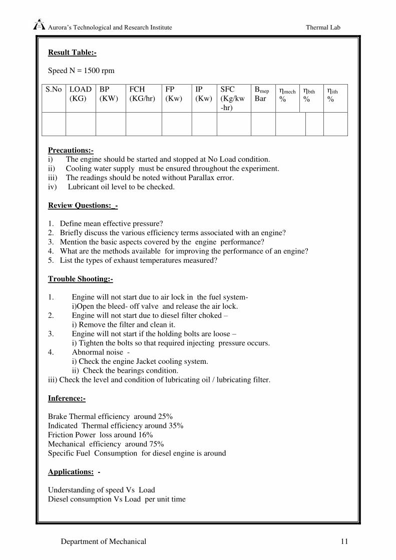
Result Table:-
Speed N = 1500 rpm
S.No LOAD
(KG)
BP
(KW)
FCH
(KG/hr)
FP
(Kw)
IP
(Kw)
SFC
(Kg/kw
-hr)
Bmep
Bar mech
%
bth
%
ith
%
Precautions:-
i) The engine should be started and stopped at No Load condition.
ii) Cooling water supply must be ensured throughout the experiment.
iii) The readings should be noted without Parallax error.
iv) Lubricant oil level to be checked.
Review Questions:_-
1. Define mean effective pressure?
2. Briefly discuss the various efficiency terms associated with an engine?
3. Mention the basic aspects covered by the engine performance?
4. What are the methods available for improving the performance of an engine?
5. List the types of exhaust temperatures measured?
Trouble Shooting:-
1. Engine will not start due to air lock in the fuel system-
i)Open the bleed- off valve and release the air lock.
2. Engine will not start due to diesel filter choked –
i) Remove the filter and clean it.
3. Engine will not start if the holding bolts are loose –
i) Tighten the bolts so that required injecting pressure occurs.
4. Abnormal noise -
i) Check the engine Jacket cooling system.
ii) Check the bearings condition.
iii) Check the level and condition of lubricating oil / lubricating filter.
Inference:-
Brake Thermal efficiency around 25%
Indicated Thermal efficiency around 35%
Friction Power loss around 16%
Mechanical efficiency around 75%
Specific Fuel Consumption for diesel engine is around
Applications: -
Understanding of speed Vs Load
Diesel consumption Vs Load per unit time
Aurora’s Technological and Research Institute Thermal Lab
Department of Mechanical 12
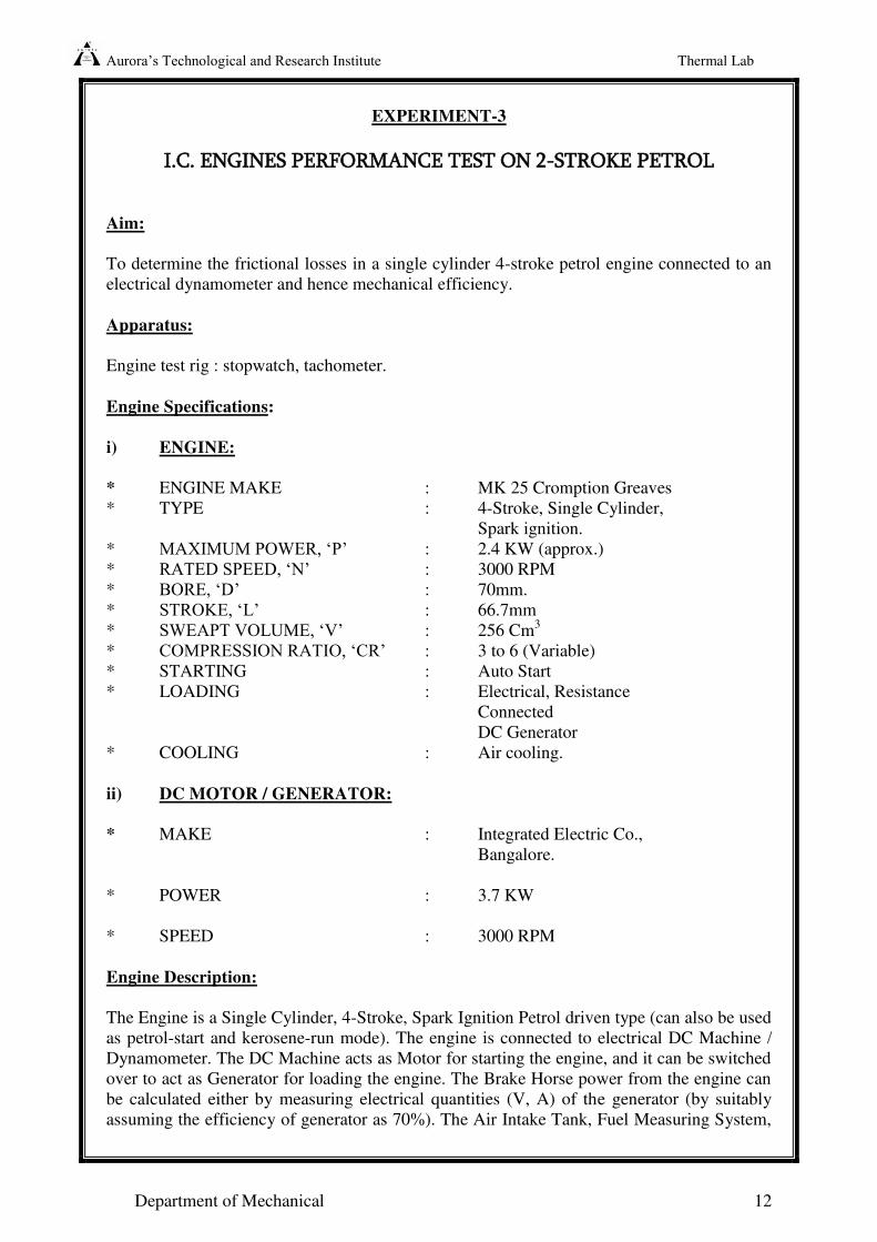
EXPERIMENT-3
I.C. ENGINES PERFORMANCE TEST ON 2-STROKE PETROL
Aim:
To determine the frictional losses in a single cylinder 4-stroke petrol engine connected to an
electrical dynamometer and hence mechanical efficiency.
Apparatus:
Engine test rig : stopwatch, tachometer.
Engine Specifications:
i) ENGINE:
* ENGINE MAKE : MK 25 Cromption Greaves
* TYPE : 4-Stroke, Single Cylinder,
Spark ignition.
* MAXIMUM POWER, ‘P’ : 2.4 KW (approx.)
* RATED SPEED, ‘N’ : 3000 RPM
* BORE, ‘D’ : 70mm.
* STROKE, ‘L’ : 66.7mm
* SWEAPT VOLUME, ‘V’ : 256 Cm3
* COMPRESSION RATIO, ‘CR’ : 3 to 6 (Variable)
* STARTING : Auto Start
* LOADING : Electrical, Resistance
Connected
DC Generator
* COOLING : Air cooling.
ii) DC MOTOR / GENERATOR:
* MAKE : Integrated Electric Co.,
Bangalore.
* POWER : 3.7 KW
* SPEED : 3000 RPM
Engine Description:
The Engine is a Single Cylinder, 4-Stroke, Spark Ignition Petrol driven type (can also be used
as petrol-start and kerosene-run mode). The engine is connected to electrical DC Machine /
Dynamometer. The DC Machine acts as Motor for starting the engine, and it can be switched
over to act as Generator for loading the engine. The Brake Horse power from the engine can
be calculated either by measuring electrical quantities (V, A) of the generator (by suitably
assuming the efficiency of generator as 70%). The Air Intake Tank, Fuel Measuring System,
Aurora’s Technological and Research Institute Thermal Lab
Department of Mechanical 13
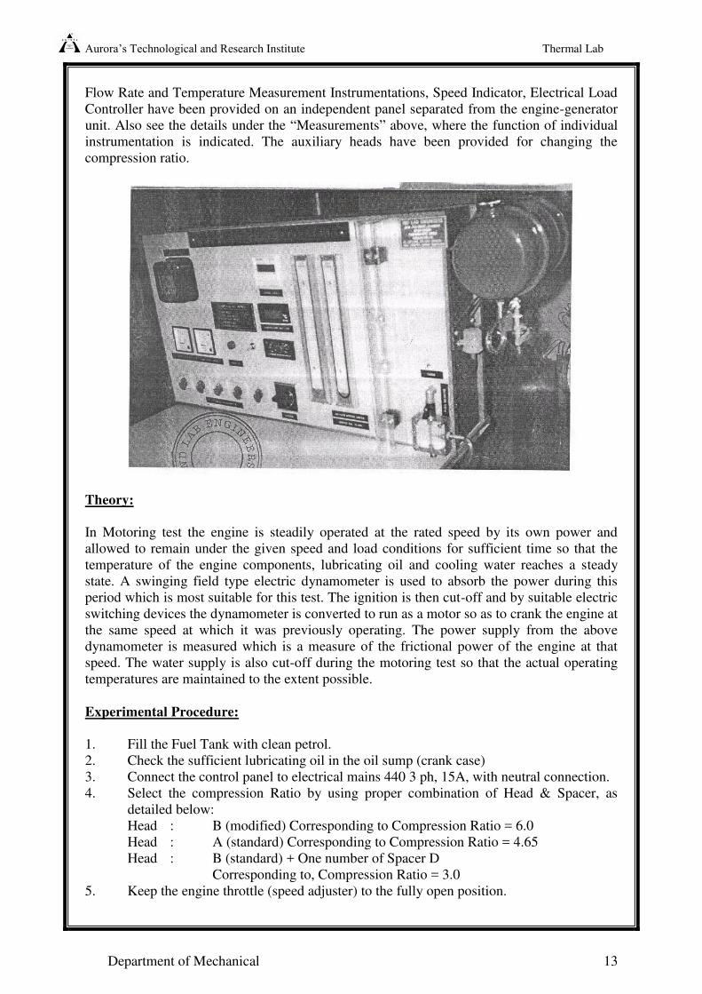
Flow Rate and Temperature Measurement Instrumentations, Speed Indicator, Electrical Load
Controller have been provided on an independent panel separated from the engine-generator
unit. Also see the details under the “Measurements” above, where the function of individual
instrumentation is indicated. The auxiliary heads have been provided for changing the
compression ratio.
Theory:
In Motoring test the engine is steadily operated at the rated speed by its own power and
allowed to remain under the given speed and load conditions for sufficient time so that the
temperature of the engine components, lubricating oil and cooling water reaches a steady
state. A swinging field type electric dynamometer is used to absorb the power during this
period which is most suitable for this test. The ignition is then cut-off and by suitable electric
switching devices the dynamometer is converted to run as a motor so as to crank the engine at
the same speed at which it was previously operating. The power supply from the above
dynamometer is measured which is a measure of the frictional power of the engine at that
speed. The water supply is also cut-off during the motoring test so that the actual operating
temperatures are maintained to the extent possible.
Experimental Procedure:
1. Fill the Fuel Tank with clean petrol.
2. Check the sufficient lubricating oil in the oil sump (crank case)
3. Connect the control panel to electrical mains 440 3 ph, 15A, with neutral connection.
4. Select the compression Ratio by using proper combination of Head & Spacer, as
detailed below:
Head : B (modified) Corresponding to Compression Ratio = 6.0
Head : A (standard) Corresponding to Compression Ratio = 4.65
Head : B (standard) + One number of Spacer D
Corresponding to, Compression Ratio = 3.0
5. Keep the engine throttle (speed adjuster) to the fully open position.
Aurora’s Technological and Research Institute Thermal Lab
Department of Mechanical 14
6. Put “ON” the Mains, and check “Mains On” Indicators in the bottom of the control
panel glow.
7. Put “ON” the Console, and check that the blower of the DC Machine is running and
all the indicating instruments glow.
8. Put the selector switch of “Motor / Generator” to “Motor” .
9. Ignition switch to “OFF” position.
10. Now, select required speed using “ Speed Control” of “Motor” .
11. Take down the readings of speed and Motor Current & Voltmeter (Digital) for
calculation of Friction Power.
Observations:
i) FRICTION POWER:
This is done by motoring the engine by disconnecting the electrical connections to
spark plug or by removing the spark plug from the position.
Friction Power = motorKWXxIV
1000
11
Multiply by 70% to account for DC Machine efficiency as motor.
Where, V1 = Motor Voltage (Digital) in Volts,
I1= Motor Current (Digital) in Amps.
Sl. No VI II FP
1
2
Precautions:
1. The engine should be run for some time before the motoring is done.
2. The engine should be started and stopped at no load condition.
3. Lubricant oil level to be checked.
Review questions:
1. Briefly discuss the various efficiency terms associated with an engine?
2. What are the methods available for improving the performance of an engine?
3. List various methods available for finding frictional power of an engine?
4. Explain the principle involved in the measurement of brake power?
Aurora’s Technological and Research Institute Thermal Lab
Department of Mechanical 15
Trouble Shooting :-
1. Engine will not start due to air lock in the fuel system-open the bleed-off volve.
2. Engine refuses to start---- Petrol tap shut off.
No petrol in the tank
Throttle disconnected too much air through carburetor.
Pilot jet blocked.
Checked petrol filter.
Fuel pump not operating.
3. Engine Started & stopped after few minutes of running –
Controls out of order
Scripper timing gear
Valve sticking
Broken valve
No valve tappet clearance.
Insufficient lubrication
Applications:-
This is very suitable for finding the losses imparted by various engines components.
Inference:-
Friction looses as in the case of pistons, bearings, gears, valve mechanisms, these
losses are usually limited from 7 to 9 percent of the indicated out put.
Power observed by engine axillaries such a fuel pump, lubricating oil pump, water
collecting pump, radiator, magneto & distributor, electric generator for battery charging etc.
These losses may account for 3 to 8 percent of the indicated out put.
Ventilating losses are usually below 4 percent of indicated out put.
Pumping losses and power observed by the scavenging pump are account 2 to 6
percent of the indicated out put.
Excusing all, the mechanical efficiency of engine varies from 65 to 85 %.
Aurora’s Technological and Research Institute Thermal Lab
Department of Mechanical 16
EXPERIMENT-4
EVALUATION OF ENGINE FRICTION BY CONDUCTING MORSE
TEST ON 4-STROKE MULTI CYLINDER PETROL ENGINE
Aim:
To conduct Morse Test on 4-stroke petrol engine and hence to determine the FRICTIONAL
POWER (FP) and MECHANICAL EFFICIENCY ( mech) of the engine.
Apparatus:
Petrol engine test rig coupled with hydraulic dynamometer, stop watch and tachometer.
Engine Specifications:-
Type : 4-cylinder, 4-stroke petrol engine.
Make : HM—1 sz
Rated Power : 75 HP at 5000 RPM
Compression Ratio : 8.5:1
Bore x Stroke : 84mm x 82mm
Clutch : Diaphragm type
Loading : By Hydraulic Dynamometer
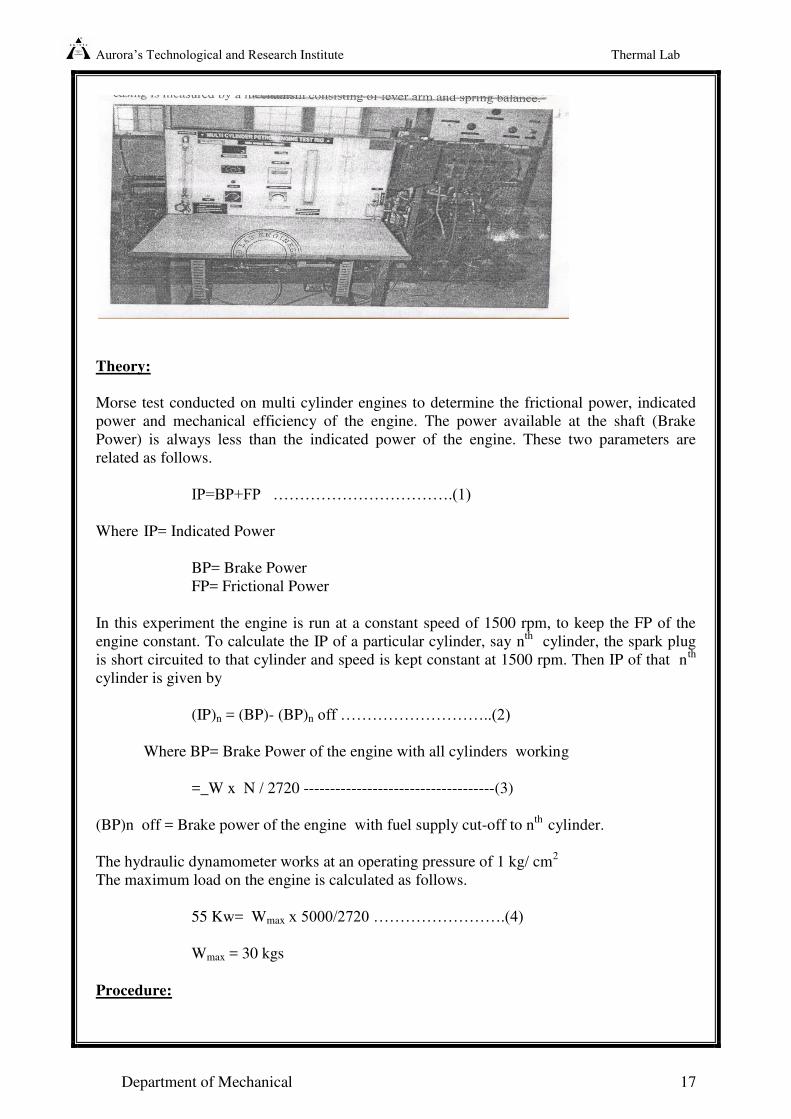
Description:
A medium capacity 4-stroke vertical water-cooled petrol engine is selected. The engine is
coupled with a hydraulic dynamometer. This consists of two half castings and a rotor
assembly or rotor shaft and coupling running on ball bearings. The principle of operation of
the unit is similar to the fluid coupling. The reaction at the casting is measured by a load cell.
The load is read from the digital indicator.
Aurora’s Technological and Research Institute Thermal Lab
Department of Mechanical 17
Theory:
Morse test conducted on multi cylinder engines to determine the frictional power, indicated
power and mechanical efficiency of the engine. The power available at the shaft (Brake
Power) is always less than the indicated power of the engine. These two parameters are
related as follows.
IP=BP+FP …………………………….(1)
Where IP= Indicated Power
BP= Brake Power
FP= Frictional Power
In this experiment the engine is run at a constant speed of 1500 rpm, to keep the FP of the
engine constant. To calculate the IP of a particular cylinder, say nth
cylinder, the spark plug
is short circuited to that cylinder and speed is kept constant at 1500 rpm. Then IP of that nth
cylinder is given by
(IP)n = (BP)- (BP)n off ………………………..(2)
Where BP= Brake Power of the engine with all cylinders working
=_W x N / 2720 ------------------------------------(3)
(BP)n off = Brake power of the engine with fuel supply cut-off to nth
cylinder.
The hydraulic dynamometer works at an operating pressure of 1 kg/ cm2
The maximum load on the engine is calculated as follows.
55 Kw= Wmax x 5000/2720 …………………….(4)
Wmax = 30 kgs
Procedure:
Aurora’s Technological and Research Institute Thermal Lab
Department of Mechanical 18
1. The Fuel level and lubricating oil level are checked.
2. The Engine is started and the load is adjusted to 8 kg at an engine speed of 1500 rpm.
3. The engine is allowed to run for some time at this condition. Then first cylinder is cut-
off by operating the lever , So that spark plug is short circuited.
4. The engine speed is adjusted to 1500 rpm by decreasing the load on the engine. The
load at which speed becomes 1500 rpm is noted. In no case the accelerator be touched
while adjusting the speed.
5. The first cylinder is put on to working condition by operating the lever and the engine is
allowed to run for some time at this state.
6. The second cylinder is cut-off and the load at which speed is maintained at 1500 rpm is
noted.
7. The above procedure is repeated for the third and fourth cylinders.
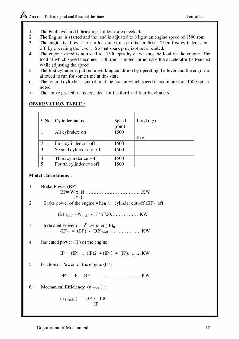
OBSERVATION TABLE :
S.No
Cylinder status
Speed
(rpm)
Load (kg)
1 All cylinders on 1500
8kg
2 First cylinder cut-off 1500
3 Second cylinder cut-off 1500
4 Third cylinder cut-off 1500
5 Fourth cylinder cut-off 1500
Model Calculations :
1. Brake Power (BP):
BP= W x N ……………………………...KW
2720
2. Brake power of the engine when nth cylinder cut-off,(BP)n off
(BP)n-off =Wn-off x N / 2720………………KW
3. Indicated Power of nth
cylinder (IP)n
(IP)n = (BP) - (BP)n-off ………………..KW
4. Indicated power (IP) of the engine:
IP = (IP)1 + (IP)2 + (IP)3 + (IP)4 ........KW
5. Frictional Power of the engine (FP) :
FP = IP - BP …………………….KW
6. Mechanical Efficiency ( mech ) :
( mech ) = BP x 100
IP
Aurora’s Technological and Research Institute Thermal Lab
Department of Mechanical 19
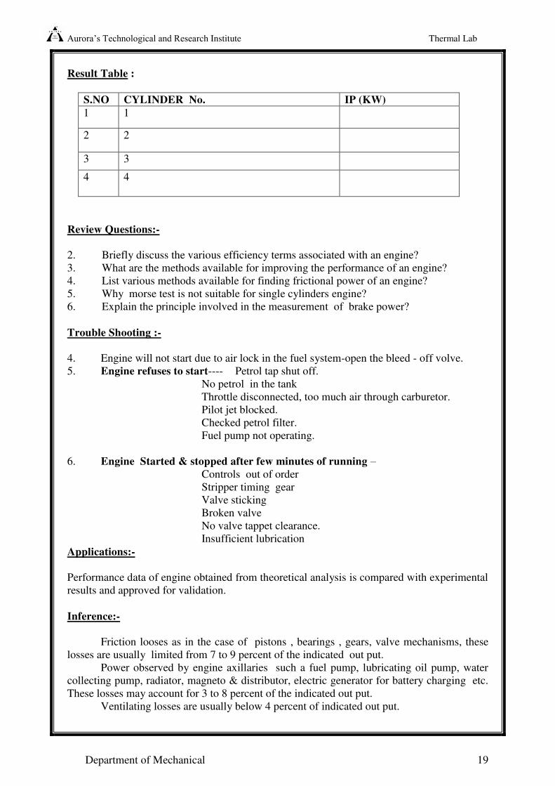
Result Table :
S.NO CYLINDER No. IP (KW)
1 1
2 2
3 3
4 4
Review Questions:-
2. Briefly discuss the various efficiency terms associated with an engine?
3. What are the methods available for improving the performance of an engine?
4. List various methods available for finding frictional power of an engine?
5. Why morse test is not suitable for single cylinders engine?
6. Explain the principle involved in the measurement of brake power?
Trouble Shooting :-
4. Engine will not start due to air lock in the fuel system-open the bleed - off volve.
5. Engine refuses to start---- Petrol tap shut off.
No petrol in the tank
Throttle disconnected, too much air through carburetor.
Pilot jet blocked.
Checked petrol filter.
Fuel pump not operating.
6. Engine Started & stopped after few minutes of running –
Controls out of order
Stripper timing gear
Valve sticking
Broken valve
No valve tappet clearance.
Insufficient lubrication
Applications:-
Performance data of engine obtained from theoretical analysis is compared with experimental
results and approved for validation.
Inference:-
Friction looses as in the case of pistons , bearings , gears, valve mechanisms, these
losses are usually limited from 7 to 9 percent of the indicated out put.
Power observed by engine axillaries such a fuel pump, lubricating oil pump, water
collecting pump, radiator, magneto & distributor, electric generator for battery charging etc.
These losses may account for 3 to 8 percent of the indicated out put.
Ventilating losses are usually below 4 percent of indicated out put.
Aurora’s Technological and Research Institute Thermal Lab
Department of Mechanical 20
Pumping losses and power observed by the scavenging pump are account 2 to 6
percent of the indicated out put.
Excusing all, the mechanical efficiency of engine varies from 65 to 85 %.
Precautions:-
1. Only one cylinder should be cut-off at a time.
2. The engine should not be operated with a cut-off cylinder for a long time.
3. The engine should be started and stopped at no load condition..
4. The load applied on the engine should not exceed the maximum load that can be applied.
5. The lubricating oil level should be maintained sufficiently.
6. Cooling water supply must ensured throughout the experiment.
Aurora’s Technological and Research Institute Thermal Lab
Department of Mechanical 21
EXPERIMENT-5
EVALUATE OF ENGINE FRICTION BY CONDUCTING
MOTORING/RETARDATION TEST ON 4 STROKE DIESEL ENGINE
Aim:
To determine the frictional power of a single cylinder 4-stroke diesel engine and hence its
mechanical efficiency.
Apparatus:
Single cylinder high speed diesel engine coupled with rope brake dynamometer stop watch.
Engine Specifications:-
Type : 4-Cylinder, 4-Stroke Diesel engine ( water
cooled
Make : Kirloskar
Speed : 1500 rpm
Compression Ratio : 16.5 : 1
Bore x Stroke : 85 mm x 110 mm
Out Put : 5 HP
Specific gravity of H.S.D. oil: 0.85 gm/ml
Calorific value : 10,000 Kcal/kg
Brake Drum Radius ; 0.185 m
Orifice diameter : 15 mm
Theory:
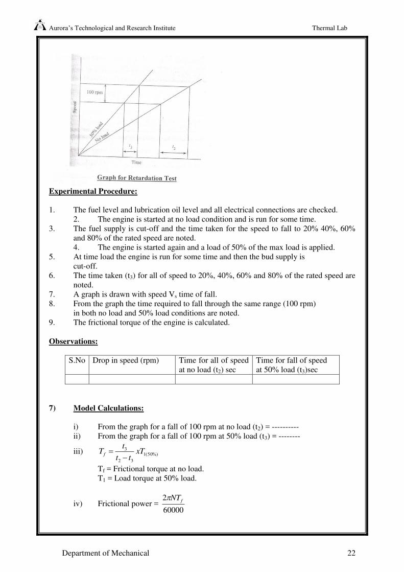
This test involves the method of retarding the engine by cutting the fuel supply. The engine is
made to run at no load and rated speed taking into all usual precautions. When the engine is
running under steady operating conditions the supply of fuel is cut-off and simultaneously the
time of fall in speeds by say 20%, 40%, 60% and 80% of the rated speed is recorded. The
tests are repeated once again with 50% load on the engine. The values are usually tabulated in
an appropriate table. A graph connecting time for all in speed (x-axis) and speed (y-axis) at
no load as well as 50% load conditions is drawn as shown in the figure given below.
Aurora’s Technological and Research Institute Thermal Lab
Department of Mechanical 22
Experimental Procedure:
1. The fuel level and lubrication oil level and all electrical connections are checked.
2. The engine is started at no load condition and is run for some time.
3. The fuel supply is cut-off and the time taken for the speed to fall to 20% 40%, 60%
and 80% of the rated speed are noted.
4. The engine is started again and a load of 50% of the max load is applied.
5. At time load the engine is run for some time and then the bud supply is
cut-off.
6. The time taken (t3) for all of speed to 20%, 40%, 60% and 80% of the rated speed are
noted.
7. A graph is drawn with speed Vs time of fall.
8. From the graph the time required to fall through the same range (100 rpm)
in both no load and 50% load conditions are noted.
9. The frictional torque of the engine is calculated.
Observations:
S.No Drop in speed (rpm) Time for all of speed
at no load (t2) sec
Time for fall of speed
at 50% load (t3)sec
7) Model Calculations:
i) From the graph for a fall of 100 rpm at no load (t2) = ----------
ii) From the graph for a fall of 100 rpm at 50% load (t3) = --------
iii) %)50(1
32
3 xTtt
tT f
Tf = Frictional torque at no load.
T1 = Load torque at 50% load.
iv) Frictional power = 60000
2 fNT
Aurora’s Technological and Research Institute Thermal Lab
Department of Mechanical 23
v) 100XFPBP
BPm
Precautions:
1. The engine should be started and stopped at No Load condition.
2. Cooling water supply and must be ensured throughout the experiment.
3. The readings should be noted without parallax error.
4. Check the lubricating oil level.
Aurora’s Technological and Research Institute Thermal Lab
Department of Mechanical 24
EXPERIMENT-6
HEAT BALANCE ON IC ENGINES.
Aim:
To conduct a test on single cylinder high-speed diesel engine and to draw the heat balance
sheet.
Apparatus:
Single cylinder high speed diesel engine coupled with rope brake dynamometer stop watch.
Engine Specifications:-
Type : 4-Cylinder, 4-Stroke Diesel
engine ( water cooled)
Make : Kirloskar
Speed : 1500 rpm
Compression Ratio : 16.5 : 1
Bore x Stroke : 85 mm x 110 mm
Out Put : 5 HP
Specific gravity of H.S.D. oil 0.85 gm/ml
Calorific value : 10,000 Kcal/kg
Brake Drum Radius ; 0.185 m
Orifice diameter : 15 mm
Theory:-
Internal combustion engines utilize the principle of burning the fuel inside the cylinder
(internal combustion). The energy released inside the cylinder goes to various forms. Only a
part of it is available at the shaft. The various forms are energy carried away by the cooling
water jacket round the cylinder, energy carried away by the exhaust gases and unaccounted
losses like due to friction, radiation etc.
A single cylinder high speed diesel engine is chosen for the experiment which runs at a
constant speed. The experiment may be carried out at 3/4th
of maximum load or ½ the
maximum load.
81.960000
.. XWDN
PB
The measurement of cooing water flow rate may be observed from the water flow water. The
cooling water flow rate should be adjusted in such a way that the outlet cooling water
temperature is maintained in between 45 to 50 degrees. After achieving this state only the
readings should be noted. The mass flow rate of air intake may be measured from the orifice
water manometer arrangement.
The sum of the mass flow rate of fuel and mass flow rate of intake air gives the mass flow
rate of exhaust gases.
Aurora’s Technological and Research Institute Thermal Lab
Department of Mechanical 25
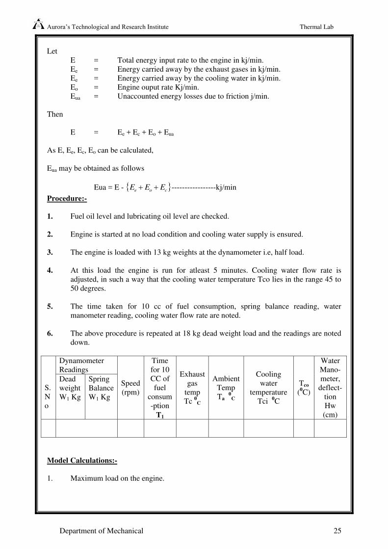
Let
E = Total energy input rate to the engine in kj/min.
Ee = Energy carried away by the exhaust gases in kj/min.
Ee = Energy carried away by the cooling water in kj/min.
Eo = Engine ouput rate Kj/min.
Eua = Unaccounted energy losses due to friction j/min.
Then
E = Ee + Ec + Eo + Eua
As E, Ee, Ec, Eo can be calculated,
Eua may be obtained as follows
Eua = E - coe EEE -----------------kj/min
Procedure:-
1. Fuel oil level and lubricating oil level are checked.
2. Engine is started at no load condition and cooling water supply is ensured.
3. The engine is loaded with 13 kg weights at the dynamometer i.e, half load.
4. At this load the engine is run for atleast 5 minutes. Cooling water flow rate is
adjusted, in such a way that the cooling water temperature Tco lies in the range 45 to
50 degrees.
5. The time taken for 10 cc of fuel consumption, spring balance reading, water
manometer reading, cooling water flow rate are noted.
6. The above procedure is repeated at 18 kg dead weight load and the readings are noted
down.
S.
N
o
Dynamometer
Readings
Speed
(rpm)
Time
for 10
CC of
fuel
consum
-ption
T1
Exhaust
gas
temp
Tc 0
C
Ambient
Temp
Ta 0
C
Cooling
water
temperature
Tci 0C
Tco
(0C)
Water
Mano-
meter,
deflect-
tion
Hw
(cm)
Dead
weight
W1 Kg
Spring
Balance
W1 Kg
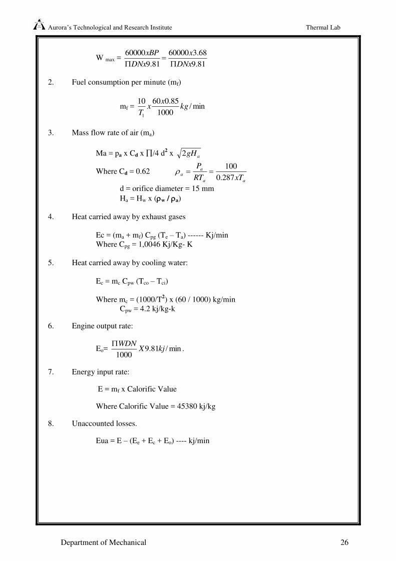
Model Calculations:-
1. Maximum load on the engine.
Aurora’s Technological and Research Institute Thermal Lab
Department of Mechanical 26
W max = 81.9
68.360000
81.9
60000
DNx
x
DNx
xBP
2. Fuel consumption per minute (mf)
mf = min/1000
85.06010
1
kgx
xT
3. Mass flow rate of air (ma)
Ma = pa x Cd x /4 d2 x agH2
Where Cd = 0.62 aa
a
axTRT
P
287.0
100
d = orifice diameter = 15 mm
Ha = Hw x (w / a)
4. Heat carried away by exhaust gases
Ec = (ma + mf) Cpg (Te – Ta) ------ Kj/min
Where Cpg = 1,0046 Kj/Kg- K
5. Heat carried away by cooling water:
Ec = mc Cpw (Tco – Tci)
Where mc = (1000/T2) x (60 / 1000) kg/min
Cpw = 4.2 kj/kg-k
6. Engine output rate:
Eo= .min/81.91000
kjXWDN
7. Energy input rate:
E = mf x Calorific Value
Where Calorific Value = 45380 kj/kg
8. Unaccounted losses.
Eua = E – (Ee + Ec + Eo) ---- kj/min
Aurora’s Technological and Research Institute Thermal Lab
Department of Mechanical 27
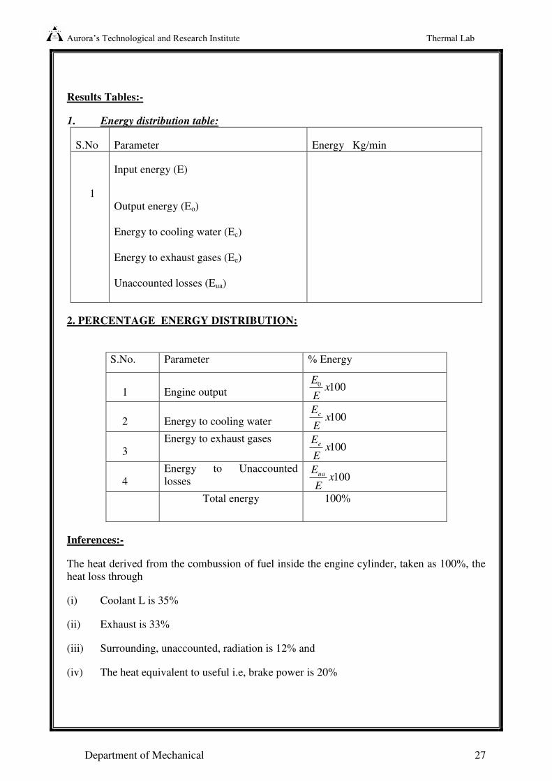
Results Tables:-
1. Energy distribution table:
S.No Parameter Energy Kg/min
1
Input energy (E)
Output energy (Eo)
Energy to cooling water (Ec)
Energy to exhaust gases (Ee)
Unaccounted losses (Eua)
2. PERCENTAGE ENERGY DISTRIBUTION:
S.No. Parameter % Energy
1
Engine output 1000 x
E
E
2
Energy to cooling water 100xE
Ec
3
Energy to exhaust gases 100x
E
Ee
4
Energy to Unaccounted
losses 100xE
Eua
Total energy 100%
Inferences:-
The heat derived from the combussion of fuel inside the engine cylinder, taken as 100%, the
heat loss through
(i) Coolant L is 35%
(ii) Exhaust is 33%
(iii) Surrounding, unaccounted, radiation is 12% and
(iv) The heat equivalent to useful i.e, brake power is 20%
Aurora’s Technological and Research Institute Thermal Lab
Department of Mechanical 28
Review Questions :
1) Explain the energy flow through an engine by means of diagrams/graphs?
2) What are the methods available for improving the performance of an engine?
3) List the types of exhaust temperatures measured?
4) Define specific fuel consumption (SFC)?
5) What are the various energy losses in engines?
6) What are the various methods of engine cooling.?
7) What are the various lubricating methods of an engine.
Trouble Shooting:-
1. Engine will not start due to air lock in the fuel system-
i)Open the bleed- off valve and release the air lock.
2. Engine will not start due to diesel filter choked –
i) Remove the filter and clean it.
3. Engine will not start if the holding bolts are loose –
i) Tighten the bolts so that required injecting pressure occurs.
4. Abnormal noise -
i) Check the engine Jacket cooling system.
ii) Check the bearings condition.
iii) Check the level and condition of lubricating oil / lubricating filter.
Applications:-
a) To give sufficient data for the preparation of a heat balance sheet, which include
method of determining frictional power and the measurement of speed, load fuel
consumption, and consumption, exhaust temperature and temperature rise of cooling
water.
b) This heat balance, sheet makes it possible to account for the heat supplied by the fuel
and indicate its proper distribution.
Precautions:-
1. The engine should be started and stopped at No Load condition.
2. Cooling water must be ensured throughout the experiment.
3. The engine should be run for sufficient time so that steady state are be
attained.
4. The manometer readings should be noted without parallax error.
5. Lubricant oil level to be checked.
Aurora’s Technological and Research Institute Thermal Lab
Department of Mechanical 29
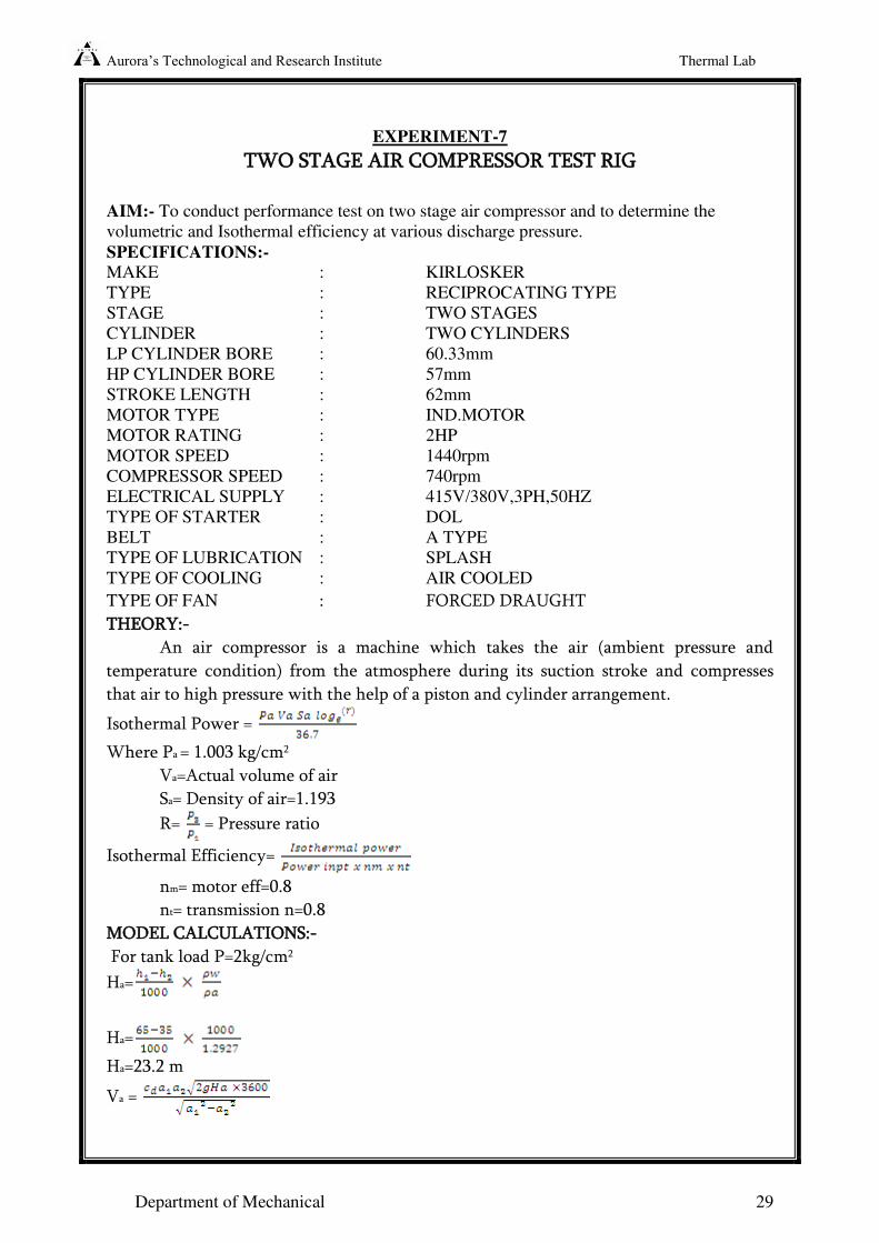
EXPERIMENT-7
TWO STAGE AIR COMPRESSOR TEST RIG
AIM:- To conduct performance test on two stage air compressor and to determine the
volumetric and Isothermal efficiency at various discharge pressure.
SPECIFICATIONS:-
MAKE : KIRLOSKER
TYPE : RECIPROCATING TYPE
STAGE : TWO STAGES
CYLINDER : TWO CYLINDERS
LP CYLINDER BORE : 60.33mm
HP CYLINDER BORE : 57mm
STROKE LENGTH : 62mm
MOTOR TYPE : IND.MOTOR
MOTOR RATING : 2HP
MOTOR SPEED : 1440rpm
COMPRESSOR SPEED : 740rpm
ELECTRICAL SUPPLY : 415V/380V,3PH,50HZ
TYPE OF STARTER : DOL
BELT : A TYPE
TYPE OF LUBRICATION : SPLASH
TYPE OF COOLING : AIR COOLED
TYPE OF FAN : FORCED DRAUGHT
THEORY:-
An air compressor is a machine which takes the air (ambient pressure and
temperature condition) from the atmosphere during its suction stroke and compresses
that air to high pressure with the help of a piston and cylinder arrangement.
Isothermal Power =
Where Pa = 1.003 kg/cm2
Va=Actual volume of air
Sa= Density of air=1.193
R= = Pressure ratio
Isothermal Efficiency=
nm= motor eff=0.8
nt= transmission n=0.8
MODEL CALCULATIONS:-
For tank load P=2kg/cm2
Ha=
Ha=
Ha=23.2 m
Va =
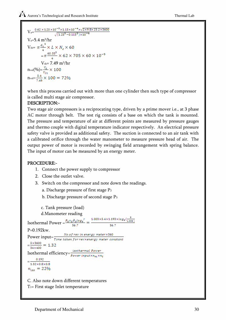
Aurora’s Technological and Research Institute Thermal Lab
Department of Mechanical 30
Va=
Va=5.4 m3/hr
Vth=
=
Vth= 7.49 m3/hr
nvol(%)=
nvol=
when this process carried out with more than one cylinder then such type of compressor
is called multi stage air compressor.
DESCRIPTION:-
Two stage air compressors is a reciprocating type, driven by a prime mover i.e., at 3 phase
AC motor through belt. The test rig consists of a base on which the tank is mounted.
The pressure and temperature of air at different points are measured by pressure gauges
and thermo couple with digital temperature indicator respectively. An electrical pressure
safety valve is provided as additional safety. The suction is connected to an air tank with
a calibrated orifice through the water manometer to measure pressure head of air. The
output power of motor is recorded by swinging field arrangement with spring balance.
The input of motor can be measured by an energy meter.
PROCEDURE:-
1. Connect the power supply to compressor
2. Close the outlet valve.
3. Switch on the compressor and note down the readings.
a. Discharge pressure of first stage P2
b. Discharge pressure of second stage P3
c. Tank pressure (load)
d.Manometer reading
Isothermal Power =
P=0.192kw.
Power input=
=
Isothermal efficiency=
=
C. Also note down different temperatures
T1= First stage Inlet temperature
Aurora’s Technological and Research Institute Thermal Lab
Department of Mechanical 31
T2= First stage outlet temperature
T3= second stage Inlet temperature
T4=Second stage outlet temperature
4. Not down the energy meter reading
5. Repeat the experiments for different delivery pressure.
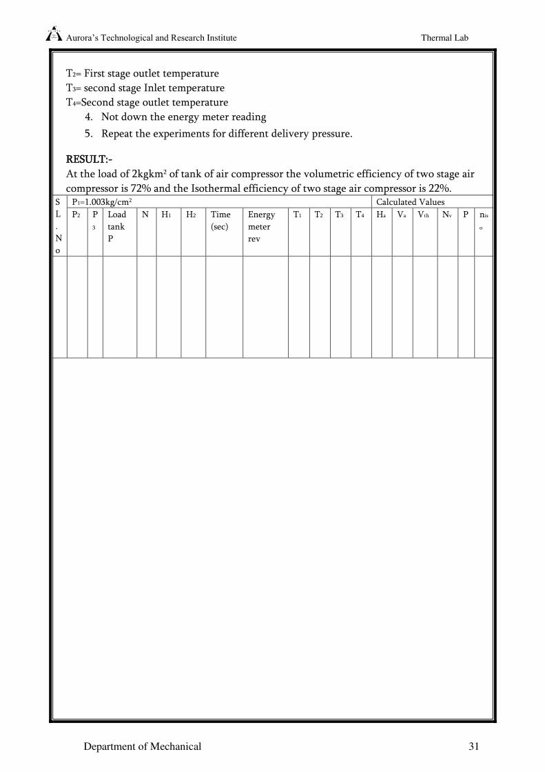
RESULT:-
At the load of 2kgkm2 of tank of air compressor the volumetric efficiency of two stage air
compressor is 72% and the Isothermal efficiency of two stage air compressor is 22%. S
L
.
N
o
P1=1.003kg/cm2 Calculated Values
P2 P
3
Load
tank
P
N H1 H2 Time
(sec)
Energy
meter
rev
T1 T2 T3 T4 Ha Va Vth Nv P nis
o
Aurora’s Technological and Research Institute Thermal Lab
Department of Mechanical 32
EXPERIMENT-8
STUDY OF STEAM BOILERS
Introduction:
A steam generator or boiler is, usually, a closed vessel made of steel. Its function is to
transfer the heat produced by the combustion of fuel (solid, liquid or gaseous) to water, and
ultimately to generate steam. The steam produced may be supplied.
1. to an external combustion engine, i.e. steam engines and turbines.
2. at low pressures for industrial process work in cotton mills, sugar
factories, breweries, etc.
3. for producing hot water, which can be used for heating installations at
much lower pressure.
Important terms:
1. Boiler shell: It is made up of steel plates bent into cylindrical form and riveted or
welded together. The ends of the shell are closed by means of end plates. A boiler
shell should have sufficient capacity to contain water and steam.
2. Combustion chamber: It is the space, generally below the boiler shell, meant for
burning fuel in order to produce steam from the water contained in the shell.
3. Grate: It is a platform, in the combustion chamber, upon which fuel (coal or wood) is
burnt. The great, generally, consists of cast iron bars which are spaced apart so that air
(required for combustion) can pas through them. The surface area of the grate, over
which the fire takes place, is called great surface.
4. Furnace: It is the space, above the grate and below the boiler shell, in which the fuel
is actually burnt. The furnace is also called fire box.
5. Heating surface: It is that part of boiler surface, which is exposed to the fire (or hot
gases from the fire).
6. Mountings: These are the fittings which are mounted on the boiler for its proper
functioning. They include water level indicator, pressure gauge, safety valve etc. It
may be noted that a boiler cannot function safely without the mountings.
7. Accessoreies: These are the devices, which form an integral part of a boiler, but are
not mounted on it. They include super heater, economizer, feed pump etc. It may be
noted that the accessories help in controlling and running the boiler efficiently.
2) CLASSIFICATION OF STEM BOILERS.
Though there are many classification of steam boilers, yet the following are important from
the subject point of view.
1. According to the contents in the tube: The steam boilers, according to the contents
in the tube may be classified as:
Aurora’s Technological and Research Institute Thermal Lab
Department of Mechanical 33
(a) Fire tube or smoke tube boiler, and (b) Water tube boiler.
In fire tube steam boilers, the flames and hot gasses, produced by the combustion of
fuels, pass through the tubes (called multi-tubes) which are surrounded by water. The
heat is conducted through the walls of the tubes from the hot gases to the surrounding
water. Examples of fire tube boilers are: Simple vertical boiler, Cochran boiler,
Lancashire boiler, Cornish boiler, Scotch marine boiler, Locomotive boiler, and
Velcon boiler.
In Water tube steam boilers, the water is contained inside the tubes (called water
tubes) which are surrounded by flames and hot gases from outside. Examples of water
tube boilers are: Babcock and Wilcox boiler, Stirling boiler, La-Mont boiler, Benson
boiler, Yarrow boiler and Loeffler boiler.
2. According to the position of the furnace: The steam boilers, according to the
position of the furnace are classified as:
(b) Internally fired boilers, and (b) Externally boilers.
In Internally fired steam boilers, the furnace is located inside the boiler shell.
Most of the fire tube steam boilers are internally fired.
In externally fired steam boilers, the furnace is arranged underneath in a brick work
setting. Water tube steam boilers are always externally fired.
3. According to the axis of the shell: The steam boilers, according to the axis of the
shell, may be classified as:
(c) Vertical boilers, and (b) Horizontal boilers.
In vertical steam boilers, the axis of the shell is vertical. Simple vertical boiler and
Cochran boiler are vertical boilers.
In horizontal steam boilers, the axis of the shell is horizontal. Lancashire boiler,
Locomotive boiler and Babcock and Wilcox boiler are horizontal boilers.
4. According to the number of tubes: The steam boilers, according to the number of
tubes, may be classified as:
(a) Single tube boilers, and (b) Multitubular boilers.
In single tube steam boilers, there is only one fire tube or water tube. Simple vertical
boiler and Cornish boiler are single tube boilers.
In multitubular steam boilers, there are two or more fire tubes or water tubes.
Lancashire boiler, Locomotive boiler, Cochran boiler, Babcock and Wilcox boiler are
multitubular boilers.
Aurora’s Technological and Research Institute Thermal Lab
Department of Mechanical 34
5. According to the method of circulation of water and steam:
The steam boilers, according to the method of circulation of water and steam, may be
classified as:
(a) Natural circulation boilers, and (b) Forced circulation boilers.
In Natural circulation steam boilers, the circulation of water is by natural convection
currents, which are set up during the heating of water. In most of the steam boilers,
there is a natural circulation of water.
In forced circulation steam boilers, there is a forced circulation of water by a
centrifugal pump driven by some external power. Use of forced circulation is made in
high pressure boilers such as La-Mont boiler, Benson Boiler, Loeffler boiler and Velcon
boiler.
7. According to the use: The steam boilers, according to their use, may be classified as:
(a) Stationary boilers, and (b) Mobile boilers.
The Stationary steam bioers are used in power plants, and in industrial process work.
These are called stationary because they do not move from one place to another.
The mobile steam boilers are those which move from one place to another. These
boilers are locomotive and marine boilers.
8. According to the source of heat: The steam boilers may also be classified according
to the source of heat supplied for producing steam. These sources may be the
combustion of solid, liquid or gaseous fuel, hot waste gases as by products of other
chemical processes, electrical energy or nuclear energy etc.
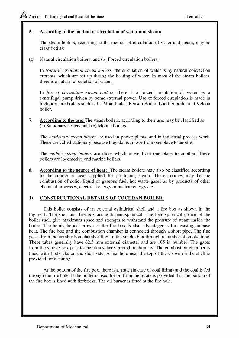
1) CONSTRUCTIONAL DETAILS OF COCHRAN BOILER:
This boiler consists of an external cylindrical shell and a fire box as shown in the
Figure 1. The shell and fire box are both hemispherical, The hemispherical crown of the
boiler shell give maximum space and strength to withstand the pressure of steam inside the
boiler. The hemispherical crown of the fire box is also advantageous for resisting intense
heat. The fire box and the combustion chamber is connected through a short pipe. The flue
gases from the combustion chamber flow to the smoke box through a number of smoke tube.
These tubes generally have 62.5 mm external diameter and are 165 in number. The gases
from the smoke box pass to the atmosphere through a chimney. The combustion chamber is
lined with firebricks on the shell side. A manhole near the top of the crown on the shell is
provided for cleaning.
At the bottom of the fire box, there is a grate (in case of coal firing) and the coal is fed
through the fire hole. If the boiler is used for oil firing, no grate is provided, but the bottom of
the fire box is lined with firebricks. The oil burner is fitted at the fire hole.
Aurora’s Technological and Research Institute Thermal Lab
Department of Mechanical 35
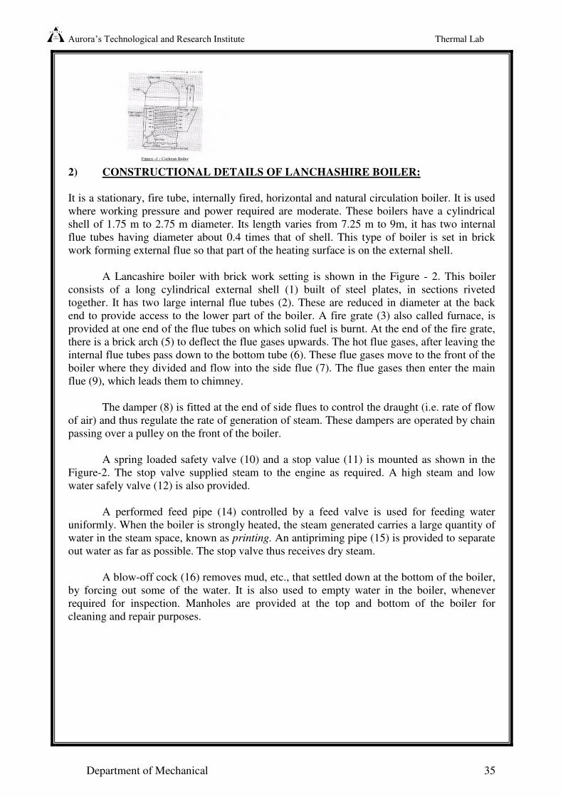
2) CONSTRUCTIONAL DETAILS OF LANCHASHIRE BOILER:
It is a stationary, fire tube, internally fired, horizontal and natural circulation boiler. It is used
where working pressure and power required are moderate. These boilers have a cylindrical
shell of 1.75 m to 2.75 m diameter. Its length varies from 7.25 m to 9m, it has two internal
flue tubes having diameter about 0.4 times that of shell. This type of boiler is set in brick
work forming external flue so that part of the heating surface is on the external shell.
A Lancashire boiler with brick work setting is shown in the Figure - 2. This boiler
consists of a long cylindrical external shell (1) built of steel plates, in sections riveted
together. It has two large internal flue tubes (2). These are reduced in diameter at the back
end to provide access to the lower part of the boiler. A fire grate (3) also called furnace, is
provided at one end of the flue tubes on which solid fuel is burnt. At the end of the fire grate,
there is a brick arch (5) to deflect the flue gases upwards. The hot flue gases, after leaving the
internal flue tubes pass down to the bottom tube (6). These flue gases move to the front of the
boiler where they divided and flow into the side flue (7). The flue gases then enter the main
flue (9), which leads them to chimney.
The damper (8) is fitted at the end of side flues to control the draught (i.e. rate of flow
of air) and thus regulate the rate of generation of steam. These dampers are operated by chain
passing over a pulley on the front of the boiler.
A spring loaded safety valve (10) and a stop value (11) is mounted as shown in the
Figure-2. The stop valve supplied steam to the engine as required. A high steam and low
water safely valve (12) is also provided.
A performed feed pipe (14) controlled by a feed valve is used for feeding water
uniformly. When the boiler is strongly heated, the steam generated carries a large quantity of
water in the steam space, known as printing. An antipriming pipe (15) is provided to separate
out water as far as possible. The stop valve thus receives dry steam.
A blow-off cock (16) removes mud, etc., that settled down at the bottom of the boiler,
by forcing out some of the water. It is also used to empty water in the boiler, whenever
required for inspection. Manholes are provided at the top and bottom of the boiler for
cleaning and repair purposes.
Aurora’s Technological and Research Institute Thermal Lab
Department of Mechanical 36
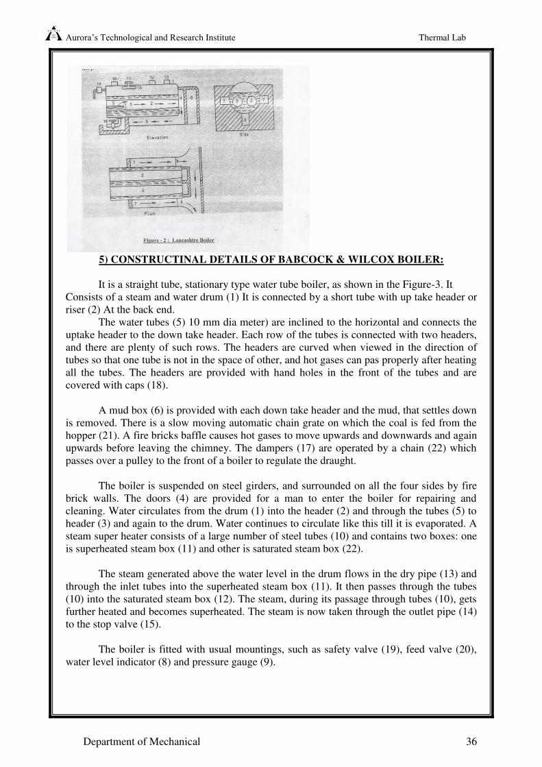
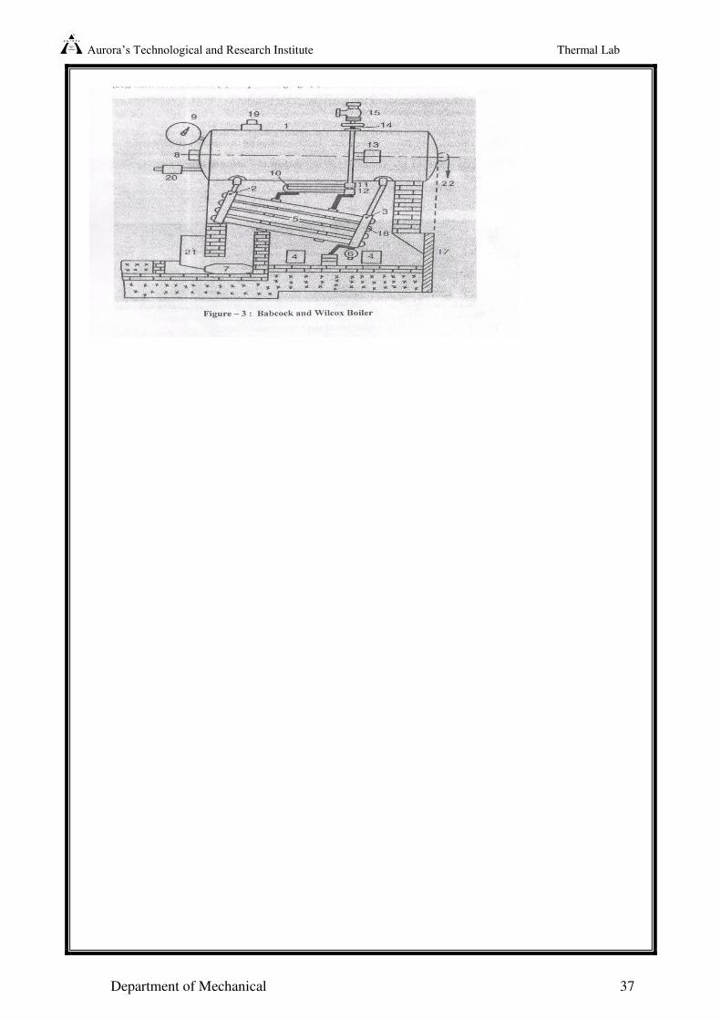
5) CONSTRUCTINAL DETAILS OF BABCOCK & WILCOX BOILER:
It is a straight tube, stationary type water tube boiler, as shown in the Figure-3. It
Consists of a steam and water drum (1) It is connected by a short tube with up take header or
riser (2) At the back end.
The water tubes (5) 10 mm dia meter) are inclined to the horizontal and connects the
uptake header to the down take header. Each row of the tubes is connected with two headers,
and there are plenty of such rows. The headers are curved when viewed in the direction of
tubes so that one tube is not in the space of other, and hot gases can pas properly after heating
all the tubes. The headers are provided with hand holes in the front of the tubes and are
covered with caps (18).
A mud box (6) is provided with each down take header and the mud, that settles down
is removed. There is a slow moving automatic chain grate on which the coal is fed from the
hopper (21). A fire bricks baffle causes hot gases to move upwards and downwards and again
upwards before leaving the chimney. The dampers (17) are operated by a chain (22) which
passes over a pulley to the front of a boiler to regulate the draught.
The boiler is suspended on steel girders, and surrounded on all the four sides by fire
brick walls. The doors (4) are provided for a man to enter the boiler for repairing and
cleaning. Water circulates from the drum (1) into the header (2) and through the tubes (5) to
header (3) and again to the drum. Water continues to circulate like this till it is evaporated. A
steam super heater consists of a large number of steel tubes (10) and contains two boxes: one
is superheated steam box (11) and other is saturated steam box (22).
The steam generated above the water level in the drum flows in the dry pipe (13) and
through the inlet tubes into the superheated steam box (11). It then passes through the tubes
(10) into the saturated steam box (12). The steam, during its passage through tubes (10), gets
further heated and becomes superheated. The steam is now taken through the outlet pipe (14)
to the stop valve (15).
The boiler is fitted with usual mountings, such as safety valve (19), feed valve (20),
water level indicator (8) and pressure gauge (9).
Aurora’s Technological and Research Institute Thermal Lab
Department of Mechanical 37