Embed Size (px)
Citation preview
Charles Forsberg
Department of Nuclear Science and EngineeringMassachusetts Institute of Technology
77 Massachusetts Ave; Bld. 42-207a; Cambridge, MA 02139Tel: (617) 324-4010; Email: [email protected]
Thermal Energy Storage Systems for Peak Electricity from Nuclear Energy
Gigawatt-day to Gigawatt-year
MIT Center for Advanced Nuclear Energy Systems
ARPA-E Workshop on Thermal Energy StorageWashington D.C.January 31, 2011
File: Nuclear Renewable Futures; ARPA-E Thermal Storage…
Outline
Energy storage requirements (Utility sector)
Nuclear thermal-energy storage constraints
Example nuclear thermal-storage systems Heat for peak electricity Heat for commercial and industrial customers
2
3
Utility Energy Storage Requirements for a Low-Carbon World

Dem
and
(104
MW
(e))
Time (hours since beginning of year)
Electricity Demand Varies By The Hour, Day, Week and Year
New England Electrical Gird
4
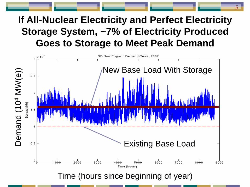
Existing Base Load2/3 Electricity Demand
Traditional Nuclear Power Market
Dem
and
(104
MW
(e))
Existing Base Load
Time (hours since beginning of year)
New Base Load With Storage
If All-Nuclear Electricity and Perfect Electricity Storage System, ~7% of Electricity Produced
Goes to Storage to Meet Peak Demand
5

Demand (Actual)
Nuclear (Projected)
Wind (Projected)
Solar (Projected))
10,000
20,000
30,000
40,000
50,000
Out
put (
MW
e)
Jan Apr Jul Oct Jan
Dates (2005)
California Demand and Production with All-Nuclear, All-Wind, or All-Solar Systems
KWh Produced/Year By Each Technology = KWh Consumed/Year
California Weekly Averaged 2005 Data Assuming All Electricity Produced By Nuclear, or Wind, or Solar Trough (With Limited Storage)
6
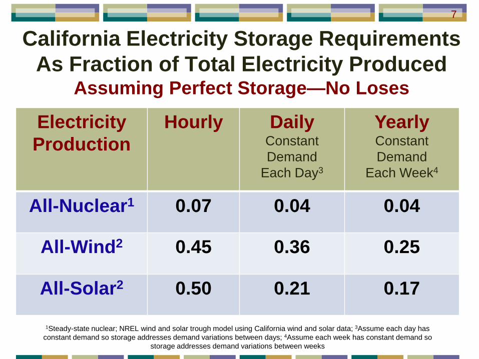
California Electricity Storage Requirements As Fraction of Total Electricity Produced
Assuming Perfect Storage—No Loses
ElectricityProduction
Hourly DailyConstant Demand
Each Day3
YearlyConstant Demand
Each Week4
All-Nuclear1 0.07 0.04 0.04
All-Wind2 0.45 0.36 0.25
All-Solar2 0.50 0.21 0.17
1Steady-state nuclear; NREL wind and solar trough model using California wind and solar data; 3Assume each day has constant demand so storage addresses demand variations between days; 4Assume each week has constant demand so
storage addresses demand variations between weeks
7
8
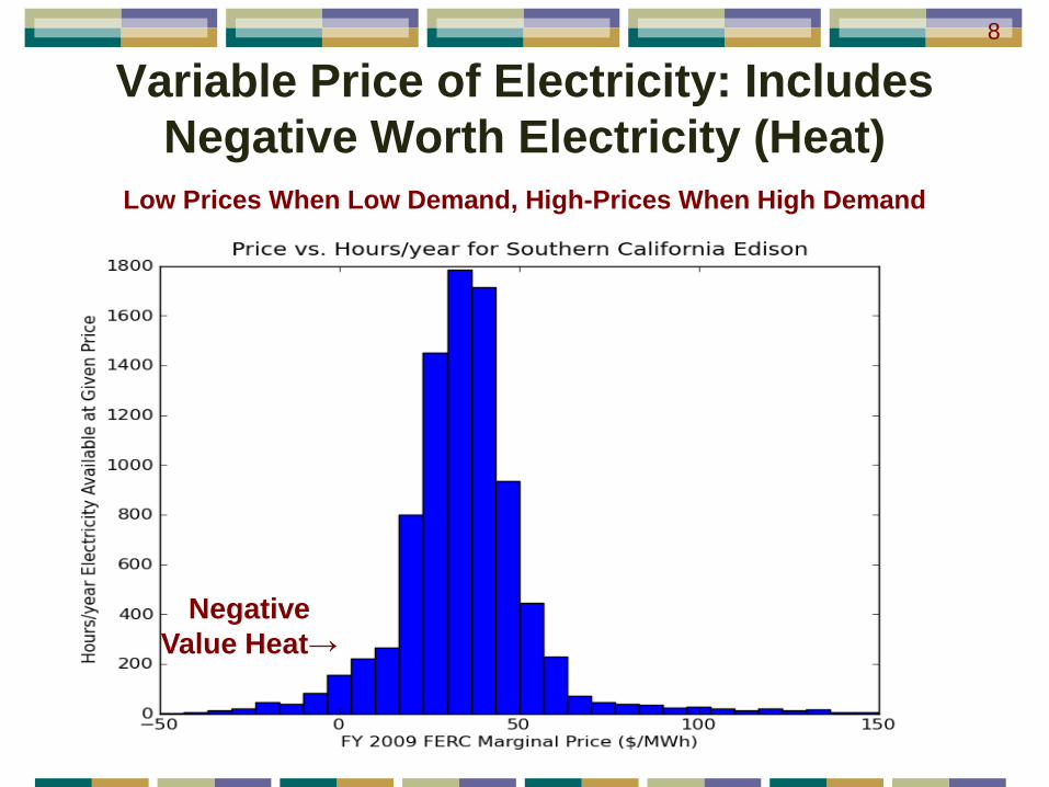
Negative Value Heat→
Variable Price of Electricity: Includes Negative Worth Electricity (Heat)
Low Prices When Low Demand, High-Prices When High Demand
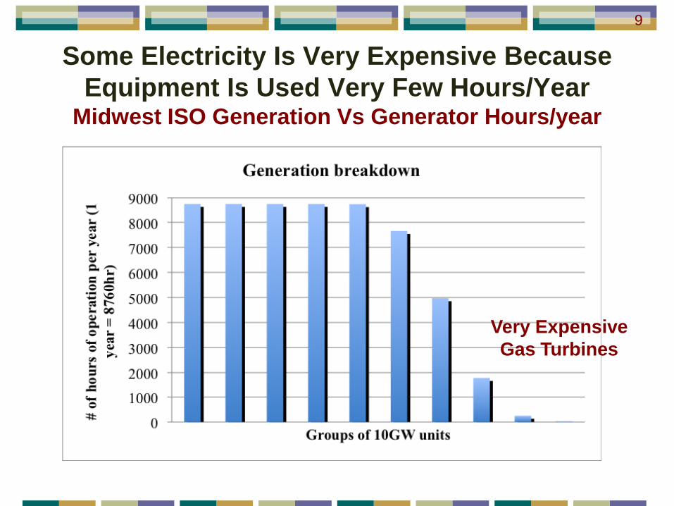
Some Electricity Is Very Expensive Because Equipment Is Used Very Few Hours/Year
Midwest ISO Generation Vs Generator Hours/year
9
Very Expensive Gas Turbines
Nuclear Thermal-Energy Storage Characteristics and Constraints
10

Minimum size: Gigawatt-hours or largerPeak Temperatures Light-Water Reactor (Today): ~275 C High-Temperature Reactor (Future): ~800 C
Large sites with security exclusion zones Storage system mass not a constraint Storage system volume unlikely to be a constraint
Reactor safety considerations Large quantities of stored energy in any viable
storage system Must consider mechanical and chemical hazards
Nuclear Thermal-Storage System Characteristics and Constraints
11
Example Nuclear Thermal Storage Technologies
Not a Comprehensive Review
12
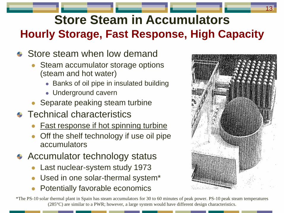
Store steam when low demand Steam accumulator storage options
(steam and hot water) Banks of oil pipe in insulated building Underground cavern
Separate peaking steam turbineTechnical characteristics Fast response if hot spinning turbine Off the shelf technology if use oil pipe
accumulatorsAccumulator technology status Last nuclear-system study 1973 Used in one solar-thermal system* Potentially favorable economics
Store Steam in AccumulatorsHourly Storage, Fast Response, High Capacity
13
*The PS-10 solar thermal plant in Spain has steam accumulators for 30 to 60 minutes of peak power. PS-10 peak steam temperatures(285°C) are similar to a PWR; however, a large system would have different design characteristics.
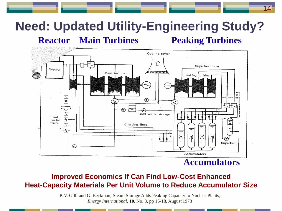
Need: Updated Utility-Engineering Study?
P. V. Gilli and G. Beckman, Steam Storage Adds Peaking Capacity to Nuclear Plants, Energy International, 10, No. 8, pp 16-18, August 1973
Reactor Main Turbines Peaking Turbines
14
AccumulatorsImproved Economics If Can Find Low-Cost Enhanced
Heat-Capacity Materials Per Unit Volume to Reduce Accumulator Size
High-Temperature Reactor Heat StorageHourly to Daily Storage: 500 to 1000°C
15
Liquid-Salt (Low Pressure) Thermal-Storage Technologies Applicable to Nuclear and Solar
MIT Concentrated Solar Power on Demand (CSPond)
Joint MIT Department of Mechanical Engineering and MIT Department of Nuclear Science and Technology Project
Includes High-Temperature Storage Technology Applicable to HTRs; Liquid Salts are Leading Candidates for Heat Transport from Reactor to Industrial Customers
16
A. Slocum, J. Buongiorno, C. W. Forsberg, T. McKrell, A. Mitsos, J. Nave, D. Codd, A. Ghobeity, C. J. Noone, S. Passerini, F. Rojas, B. “Concentrated Solar Power on Demand,” (Submitted to Solar Energy)
J. Buongiorno, C. Forsberg, T. McKrell,
A. Mitsos, J.C. Nave, A. Slocum
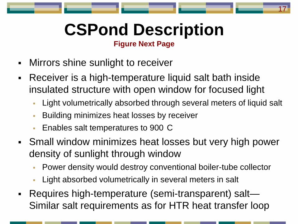
CSPond DescriptionFigure Next Page
Mirrors shine sunlight to receiver Receiver is a high-temperature liquid salt bath inside
insulated structure with open window for focused light Light volumetrically absorbed through several meters of liquid salt Building minimizes heat losses by receiver Enables salt temperatures to 900 C
Small window minimizes heat losses but very high power density of sunlight through window Power density would destroy conventional boiler-tube collector Light absorbed volumetrically in several meters in salt
Requires high-temperature (semi-transparent) salt—Similar salt requirements as for HTR heat transfer loop
17

Molten salt
Non-imaging refractory lid
Hot salt to HX
High efficiency relative to other solar systems
Liquid salt: Absorb light, storage media, and heat-transfer fluid
Beam-down heliostat field Concentrated light through small
window into insulated structure implies low heat loses
Volumetric light absorption in liquid salt (High energy flux)
Cold salt from HX
Insulated aperture
doorsLid heat
extraction
Solar-Thermal Mirror Field and Collector18

Family of High-Temperature Salt Thermal Storage Systems—All Unexplored
Morning
Evening
CSPond: Deep heat-storage salt pond (Simple option) Hot salt on top (Red) Cold salt on bottom (Blue) Insulated floating/cable-stay
separator plate Part of a larger salt heat-storage
family of options for HTRs Lack of required physical
property measurements Many variants—most lacking
key experiments to demonstrate feasibility
19
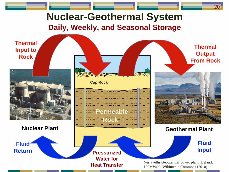
Nuclear-Geothermal SystemDaily, Weekly, and Seasonal Storage
Oil Shale
Oil Shale
Hun
dred
s of
Met
ers
Hun
dred
s of
Met
ers
RockPermeable
Cap Rock
Geothermal PlantNuclear Plant
Fluid Return
Thermal Input to
Rock
Thermal Output
From Rock
Fluid Input
Nesjavellir Geothermal power plant; Iceland; 120MW(e); Wikimedia Commons (2010)
20
Pressurized Water for
Heat Transfer
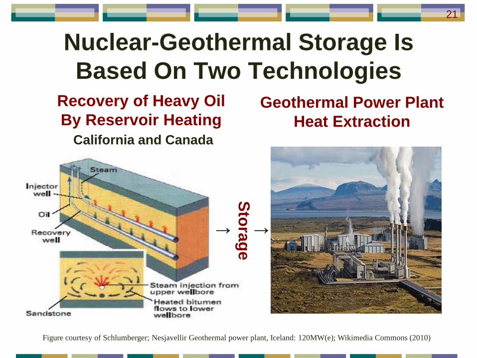
Nuclear-Geothermal Storage Is Based On Two Technologies
Recovery of Heavy Oil By Reservoir Heating
California and Canada
Geothermal Power Plant Heat Extraction
Figure courtesy of Schlumberger; Nesjavellir Geothermal power plant, Iceland: 120MW(e); Wikimedia Commons (2010)
21
↑Storage
↑
Rapid progress driven by heavy-oil and geothermal technical advancesMany ways to create permeable storage zone Hydrofracture (Oil industry technology) Cave block mining—underground rubble pile (Copper
mining) Conversion of heavy-oil reservoir to heat storage*
Technical characteristics Large scale Dependent upon the local geology May be the only economic seasonal-scale thermal
storage technologyStatus: Early technical development
Nuclear Geothermal Heat Storage22
*C. W. Forsberg, R. Krentz-Wee, Y. H. Lee, and I. O. Oloyede, Nuclear Energy for Simultaneous Low-Carbon Heavy-Oil Recovery and Gigawatt-Year Heat Storage for Peak Electricity Production, MIT-NES-TR-011, Massachusetts Institute of Technology (December 2010).
Nuclear Thermal-Energy Storage Conclusions
Massive need for energy storage on three time scales Hourly: Including rapid response Daily: 3-day weather pattern and workweek-weekend Seasonal
Nuclear thermal-energy storage options exist for each market—but significant challenges Nuclear economics demands full-load output by reactor Must consider safety—storing large quantities of energy Limited work on storage technologies—many technical challenges
Options for joint RD&D Many thermal storage systems applicable to solar and nuclear Potential for international cooperation where large incentives for storage:
France, Germany, Sweden, Spain, Japan, South Korea, Russia, and China
23
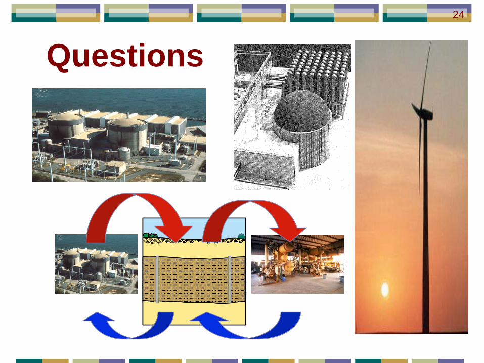
Questions
Oil ShaleOil Shale
Hun
dred
s of
Met
ers
Hun
dred
s of
Met
ers
24

Additional Information
25

Biography: Charles ForsbergDr. Charles Forsberg is the Executive Director of the Massachusetts Institute of Technology Nuclear Fuel Cycle Study. Before joining MIT, he was a Corporate Fellow at Oak Ridge National Laboratory. He is a Fellow of the American Nuclear Society, a Fellow of the American Association for the Advancement of Science, and recipient of the 2005 Robert E. Wilson Award from the American Institute of Chemical Engineers for outstanding chemical engineering contributions to nuclear energy, including his work in hydrogen production and nuclear-renewable energy futures. He received the American Nuclear Society special award for innovative nuclear reactor design. Dr. Forsberg earned his bachelor's degree in chemical engineering from the University of Minnesota and his doctorate in Nuclear Engineering from MIT. He has been awarded 11 patents and has published over 200 papers.
26
References1. C. W. Forsberg, “Sustainability by Combining Nuclear, Fossil, and Renewable Energy Sources,” Progress in Nuclear Energy, 51,
192-200 (2009)2. C. W. Forsberg, “Use of High-Temperature Heat in Refineries, Underground Refining, and Bio-Refineries for Liquid-Fuels
Production,” HTR2008-58226, 4th International Topical Meeting on High-Temperature Reactor Technology, American Society of Mechanical Engineers; September 28-October 1, 2008;Washington D.C.
3. C. W. Forsberg, “Economics of Meeting Peak Electricity Demand Using Hydrogen and Oxygen from Base-Load Nuclear or Off-Peak Electricity,” Nuclear Technology, 166, 18-26 April 2009.
4. I. Oloyede and C. Forsberg, “Implications of Gigawatt-Year Electricity Storage Systems on Future Baseload Nuclear Electricity Demand”, Paper 10117, Proc. International Congress on Advanced Nuclear Power Plants, San Diego, 15-17 June 2010.
5. Y. H. Lee, C. Forsberg, M. Driscoll, and B. Sapiie, “Options for Nuclear-Geothermal Gigawatt-Year Peak Electricity Storage Systems,” Paper 10212, Proc. International Congress on Advanced Nuclear Power Plants, San Diego, 15-17 June 2010.
6. G. Haratyk and C. Forsberg, “Integrating Nuclear and Renewables for Hydrogen and Electricity Production”, Paper 1082, Second International Meeting on the Safety and Technology of Nuclear Hydrogen Production, Control, and Management, Embedded American Nuclear Society Topical, San Diego, 15-17 June 2010.
7. C. Forsberg, “Alternative Nuclear Energy Futures: Peak Electricity, Liquid Fuels, and Hydrogen”, Paper 10076, Second International Meeting on the Safety and Technology of Nuclear Hydrogen Production, Control, and Management, Embedded American Nuclear Society Topical, San Diego, 15-17 June 2010.
8. I. Oloyede, C. W. Forsberg, M. J. Driscoll, “Gigawatt-Year Electricity Storage Requirements for Nuclear and Renewable Power Production,” American Nuclear Society Winter Meeting, Las Vegas, Nevada (Nov 2010).
9. C. W. Forsberg, “An Air-Brayton Nuclear Hydrogen Combined-Cycle Peak- and Base-Load Electric Plant,” CD-ROM, IMECE2007-43907, 2007 ASME International Mechanical Engineering Congress and Exposition, Seattle, Washington, November 11-15, 2007, American Society of Mechanical Engineers, 2007 .
10. C. W. Forsberg and James C. Conklin, Hydrogen-or-Fossil-Combustion Nuclear Combined-Cycle Systems for Base- and Peak-Load Electricity Production, ORNL-6980, Oak Ridge National Laboratory, Oak Ridge, Tennessee, September 2007.
11. J. C. Conklin and C. W. Forsberg, “Base-Load and Peak Electricity from a Combined Nuclear Heat and Fossil Combined-Cycle Power Plant,” Proc. Global 2007: Advanced Nuclear Fuel Cycles and Systems, Boise, Idaho, September 9-13, 2007, American Nuclear Society, La Grange Park, Illinois.
12. A. Slocum, J. Buongiorno, C. W. Forsberg, T. McKrell, A. Mitsos, J. Nave, D. Codd, A. Ghobeity, C. J. Noone, S. Passerini, F.Rojas, “Concentrated Solar Power on Demand,” (Submitted to Solar Energy).
13. C. W. Forsberg, R. Krentz-Wee, Y. H. Lee, and I. O. Oloyede, Nuclear Energy for Simultaneous Low-Carbon Heavy-Oil Recovery and Gigawatt-Year Heat Storage for Peak Electricity Production, MIT-NES-TR-011, Massachusetts Institute of Technology (December 2010).
27
ABSTRACT
Thermal Energy Storage Systems for Peak Electricity from Nuclear Energy
There are large incentives to operate nuclear and renewable energy sources at full output because these technologies have high capital costs and low operating costs. However, their output does not match electricity demand. Full utilization of these energy sources would be aided by storage technologies that store energy at times of low electricity demand and provide that energy for electricity or industrial use at time of high energy demand.
Nuclear and solar thermal systems produce heat; thus, thermal energy storage is a preferred form of energy storage because it avoids the inefficiencies in conversion from one storage media to another. The expectation is that many thermal storage technologies would be applicable to both energy technologies.
There are three storage markets with different requirements: hourly storage (including rapid response), weekly storage to address the 3-day weather and the weekday-weekend cycles in electricity demand, and seasonal energy storage to address the fall, winter, spring, and summer variations in energy demand. The longer term storage systems may be able to address hourly storage requirements—but not via versa.
There was significant work on thermal storage systems in the 1970s. Improved technologies may make some of these storage technologies viable today. Most of the work was associated with solar systems with a limited amount of work on storage systems for nuclear power plants. Storage systems associated with nuclear plants have somewhat different requirements: mass and volume are not usually a constraint, safety must be considered because of the very large quantities of energy being stored, and the scale of operations will be much larger.
28
Acknowledgement: We would like to thank Idaho National Laboratory for their support of R&D at MIT on nuclear geothermal systems.
29
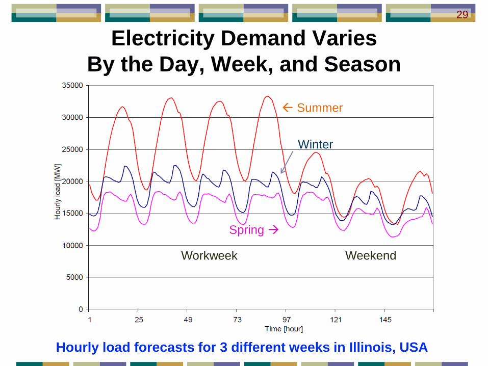
Electricity Demand Varies By the Day, Week, and Season
Hourly load forecasts for 3 different weeks in Illinois, USA
Spring
Summer
Winter
WeekendWorkweek
29

System Power Rating (MW)
MIT Gigawatt-YearHeat and Hydrogen
Dis
char
ge T
ime
(Sec
onds
)30
Storage Technologies & Capabilities
Hour
Day
Second
Year

Implications of Renewables To The Energy Storage Challenge
Characteristics Seasonal mismatch between demand and
production Rapid variation in output
Some utilities operate gas turbines at no-load to respond to loss of wind output
Significant fuel billStorage implications Need rapid response for fast wind output changes Need seasonal storage
31
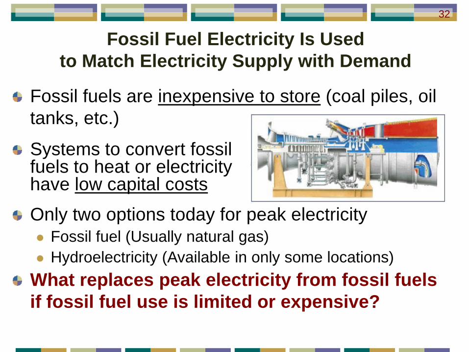
Fossil Fuel Electricity Is Used to Match Electricity Supply with Demand
Fossil fuels are inexpensive to store (coal piles, oil tanks, etc.)
Only two options today for peak electricity Fossil fuel (Usually natural gas) Hydroelectricity (Available in only some locations)
What replaces peak electricity from fossil fuels if fossil fuel use is limited or expensive?
Systems to convert fossil fuels to heat or electricity have low capital costs
32
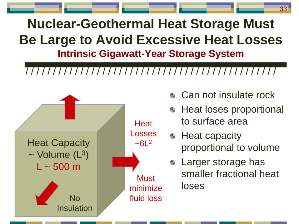
Nuclear-Geothermal Heat Storage Must Be Large to Avoid Excessive Heat Losses
Intrinsic Gigawatt-Year Storage System
Heat Capacity ~ Volume (L3)
L ~ 500 m
Can not insulate rockHeat loses proportional to surface areaHeat capacity proportional to volumeLarger storage has smaller fractional heat loses
No Insulation
/ / / / / / / / / / / / / / / / / / / / / / / / / / / / / / / / / / / / / / / / / / / / / /
Heat Losses~6L2
Must minimize fluid loss
33
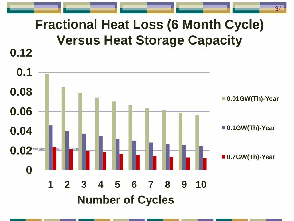
Overall Storage Round-Trip Efficiency
00.020.040.060.08
0.10.12
1 2 3 4 5 6 7 8 9 10Number of Cycles
0.01GW(Th)-Year
0.1GW(Th)-Year
0.7GW(Th)-Year
Fractional Heat Loss (6 Month Cycle) Versus Heat Storage Capacity
34
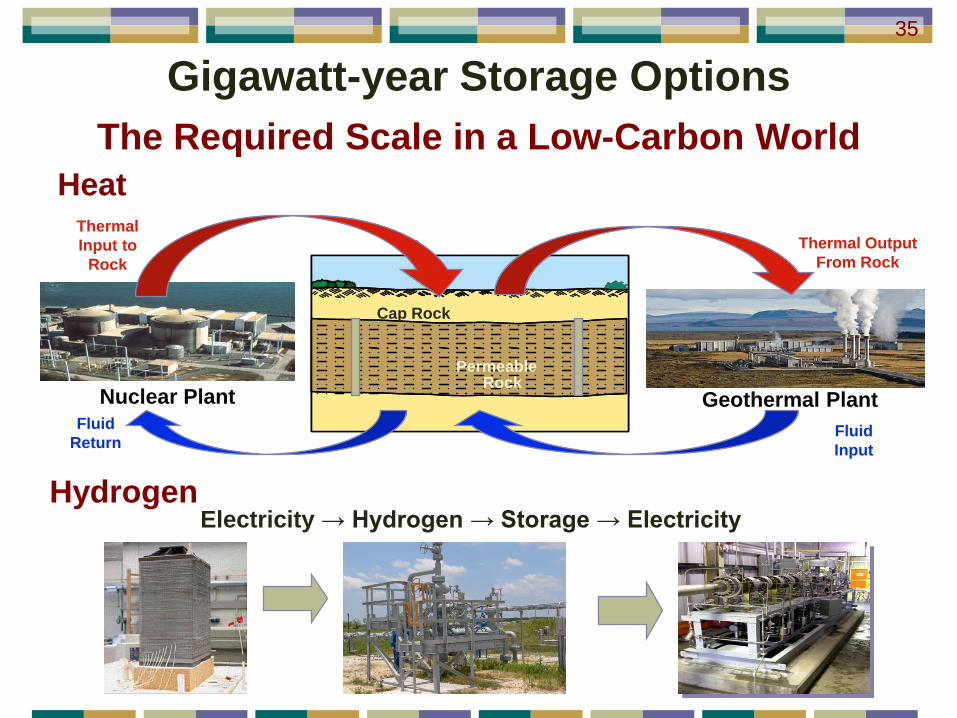
Gigawatt-year Storage OptionsThe Required Scale in a Low-Carbon World
Geothermal Plant
Oil ShaleOil ShaleHun
dred
s of
Met
ers
Hun
dred
s of
Met
ers
RockPermeable
Cap Rock
Nuclear PlantFluid
Return
Thermal Input to
RockThermal Output
From Rock
Fluid Input
Heat
HydrogenElectricity → Hydrogen → Storage → Electricity
35
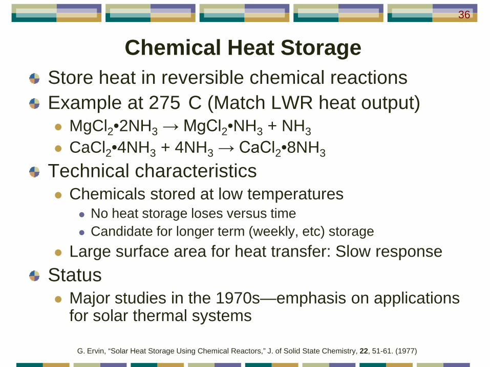
Store heat in reversible chemical reactionsExample at 275 C (Match LWR heat output) MgCl2•2NH3 → MgCl2•NH3 + NH3 CaCl2•4NH3 + 4NH3 → CaCl2•8NH3
Technical characteristics Chemicals stored at low temperatures
No heat storage loses versus time Candidate for longer term (weekly, etc) storage
Large surface area for heat transfer: Slow responseStatus Major studies in the 1970s—emphasis on applications
for solar thermal systems
Chemical Heat Storage36
G. Ervin, “Solar Heat Storage Using Chemical Reactors,” J. of Solid State Chemistry, 22, 51-61. (1977)

Nuclear Combustion Combined-Cycle (NCCC) Plant
The Other Class of Nuclear Peak-Power Systems
Low Natural Gas or Hydrogen ConsumptionVariable Electricity Output with Base-Load Nuclear
37
C. W. Forsberg, “An Air-Brayton Nuclear Hydrogen Combined-Cycle Peak- and Base-Load Electric Plant,” CD-ROM, IMECE2007-43907, 2007 ASME International Mechanical Engineering Congress and Exposition, Seattle, Washington, November 11-15, 2007, American Society of Mechanical Engineers, 2007; C. W. Forsberg and James C. Conklin, Hydrogen-or-Fossil-Combustion Nuclear Combined-Cycle Systems for Base- and Peak-Load Electricity Production, ORNL-6980, Oak Ridge National Laboratory, Oak Ridge, Tennessee, September 2007; J. C. Conklin and C. W. Forsberg, “Base-Load and Peak Electricity from a Combined Nuclear Heat and Fossil Combined-Cycle Power Plant,” Proc. Global 2007: Advanced Nuclear Fuel Cycles and Systems, Boise, Idaho, September 9-13, 2007, American Nuclear Society, La Grange Park, Illinois.
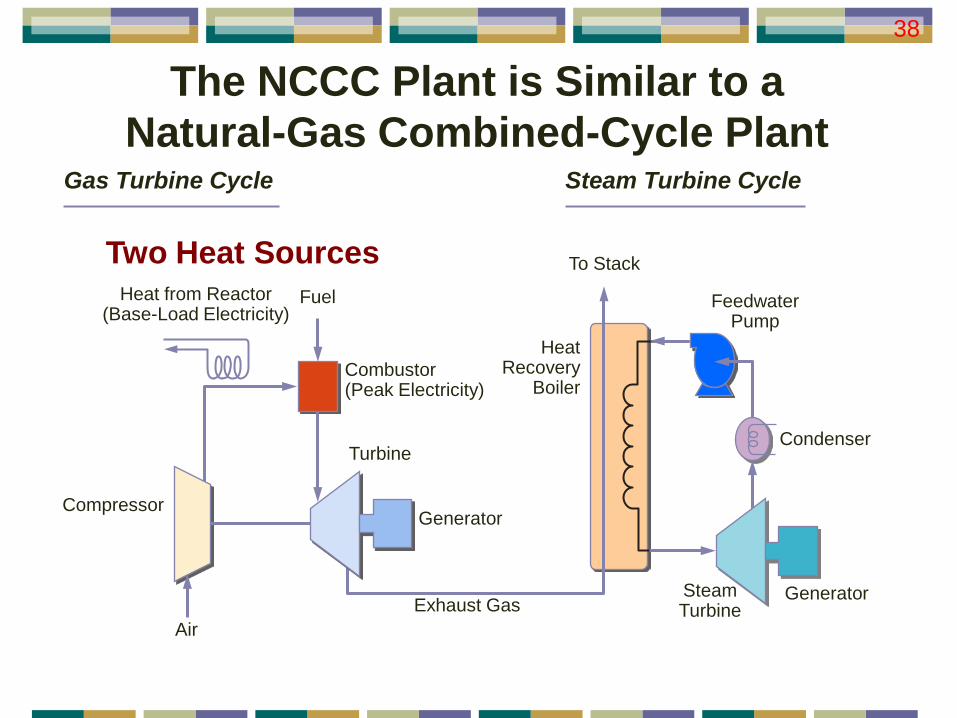
The NCCC Plant is Similar to aNatural-Gas Combined-Cycle Plant
FeedwaterPump
SteamTurbine
Generator
Condenser
To Stack
Heat Recovery
Boiler
Turbine
Generator
Steam Turbine Cycle
Exhaust Gas
Gas Turbine Cycle
Air
Compressor
Fuel
Combustor(Peak Electricity)
Heat from Reactor(Base-Load Electricity)
Two Heat Sources
38

Nuclear Heat Only NCCC Electricity Steam
Turbine Cycle
Gas Turbine Cycle
FeedwaterPump
SteamTurbine
Generator
Condenser
To Stack
Heat Recovery
Boiler
Turbine
Generator
Exhaust Gas
Air
Compressor
Fuel
Combustor(PeakElectricity)
Heat From Reactor(Base Load Electricity)
Compress airHeat air High-temperature salt 700 to 900 C
No fuel to combustor Electricity from Gas Turbine Steam Turbine
39
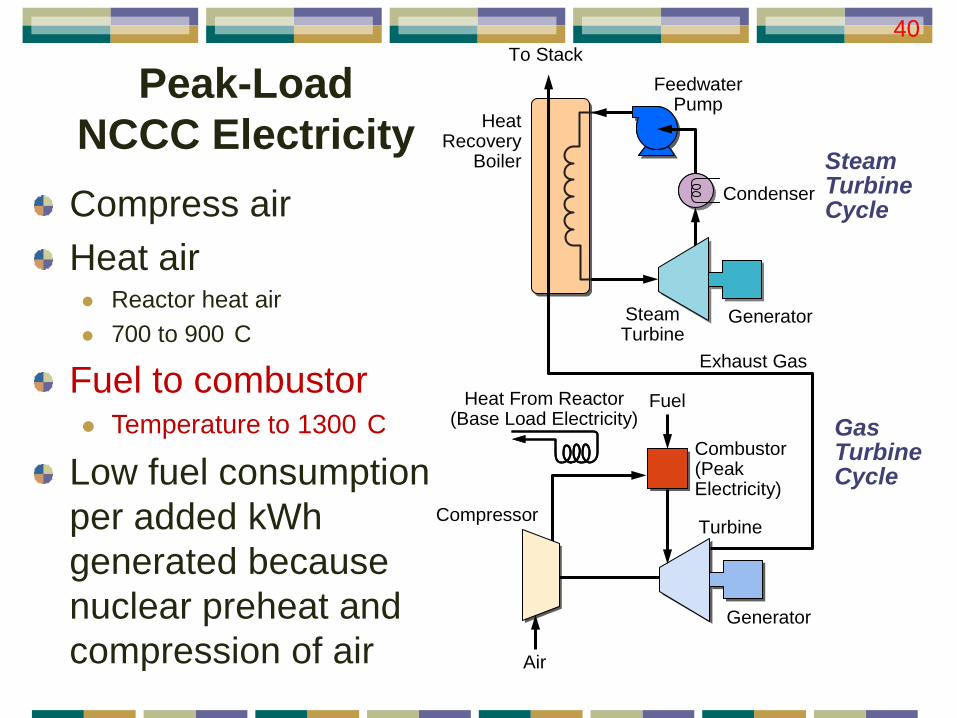
Peak-Load NCCC Electricity
Steam Turbine Cycle
Gas Turbine Cycle
FeedwaterPump
SteamTurbine
Generator
Condenser
To Stack
Heat Recovery
Boiler
Turbine
Generator
Exhaust Gas
Air
Compressor
Fuel
Combustor(PeakElectricity)
Heat From Reactor(Base Load Electricity)
Compress airHeat air Reactor heat air 700 to 900 C
Fuel to combustor Temperature to 1300 C
Low fuel consumption per added kWh generated because nuclear preheat and compression of air
40
Incentives for the NCCC To Operate AboveFuel Auto-Ignition Temperatures
Fuels spontaneously combust Jet Fuel: 240–260°C Natural gas: 630°C Hydrogen: 570°C
Implications No flame stability issues Can operate with any air-fuel ratio and thus infinite
variable power output
41

Fast Response Compared to a Natural-Gas-Fired Turbine
FeedwaterPump
SteamTurbine
Generator
Condenser
To Stack
Heat Recovery
Boiler
Turbine
Generator
Exhaust Gas
Air
Compressor
Fuel
Combustor(PeakElectricity)
Heat From Reactor(Base Load Electricity)
Characteristics Air heated above the auto-ignition
temperature so any air-fuel ratio is combustible
Compressor operates at constant speed and mass flow—powered by reactor heat. No added compressor load with increased electricity production
Response speed limited by: Valve opening speed Flight time: Injector to gas turbine Theoretical response in milliseconds
42

NCCC Features
Very low natural gas or hydrogen consumption per kWh because of nuclear heating and compression of air
Rapid response speeds
Built on existing gas-turbine technology
Dependent upon commercial deployment of high-temperature reactors
New concept—limited work
43