Embed Size (px)
Citation preview
Journal of Mechanical Science and Technology 25 (10) (2011) 2675~2682
www.springerlink.com/content/1738-494x DOI 10.1007/s12206-011-0617-3
Thermal design criteria for long-term durability of ceramic catalyst substrates†
Seok-Heum Baek1 and Seok-Swoo Cho2,* 1Department of Mechanical Engineering, Dong-A University, 840 Hadan2-dong, Busan 604-714, Korea
2Department of Vehicle Engineering, Kangwon National University, 1 Joongang-ro, Samcheok-si, Kangwon-do 245-711, Korea
(Manuscript Received September 28, 2010; Revised May 5, 2011; Accepted June 10, 2011)
----------------------------------------------------------------------------------------------------------------------------------------------------------------------------------------------------------------------------------------------------------------------------------------------
Abstract The automotive industry has traditionally used ceramic honeycomb substrates as catalyst carriers. The long-term durability of a pas-
senger car’s converter is assessed by examining the thermal stresses resulting from the temperature variations experienced under various driving conditions. These thermal stresses constitute the majority of the total stress that the ceramic catalyst substrate experiences while in service. The radial and axial temperature distributions were measured, and the thermal stress was calculated by using the thermal expansion coefficient according to the measured temperature. The threshold stress was determined from the fatigue constant, the required lifetime and the duration of the short term strength tests. The radial temperature variation was higher than the axial temperature variation, and the axial stress was higher than the radial stress because the thermal stress is dependent on the elastic modulus. The radial and axial stresses exist below the threshold thermal stress over the entire engine speed range.
Keywords: Thermal durability; Thermal stress; Threshold stress; Modulus of rupture; Ceramic catalyst substrates ---------------------------------------------------------------------------------------------------------------------------------------------------------------------------------------------------------------------------------------------------------------------------------------------- 1. Introduction
Stringent emissions regulations, such as those for national low emission vehicles (NLEV), ultra low emission vehicles (ULEV) and super ultra low emission vehicles (SULEV), have led to the development of advanced ceramic substrates, washcoat and catalyst formations along with robust packaging designs and engine control systems [1, 2]. Ceramic catalyst substrates, which directly purify the exhaust gases, should keep the noxious exhaust gases below the allowable values. Also, the ceramic catalysts need to have a tight thermal dura-bility in order to perform their role of purifying the exhaust gases at high temperatures [3-5]. Since 1990, the Korean ex-haust emissions regulations have demanded vehicles have a 5 year (80,000 km) durability, and in 2000 this requirement was raised to a 10 year (160,000 km) durability [6, 7]. In particular, the catalyst and electronic control units and their related parts must have a 7 year (120,000 km) durability. Therefore, the thermal durability of the catalysts is essential in order to pre-vent their degradation and to preserve their life cycles.
Ceramic catalyst substrates can be subject to mechanical stresses due to incorrect mounting, vibration stresses resulting from the engine and road introduced shocks and impact stresses as a result of stones hitting the vehicle. The thermal
stress, in three-way catalyst substrates, contributes substan-tially to their total stresses, and hence significantly affects the substrate durability. Also, the stress-induced corrosion mecha-nisms within the substrates lead to a gradual loss of strength over their service lives. Therefore, the designs for the thermal durability of the ceramic substrates must consider both the cycle-dependent degradation and the stress-induced corrosion mechanisms. It is necessary to determine an estimate of the ceramic substrate’s dynamic fatigue life in order to evaluate their thermal fatigue and stress corrosion cracking syntheti-cally [8].
Gulati et al. proposed that under a uniform temperature for the central region and the outer surface, radial and axial stresses in diesel particulate filter could be obtained by FEA. These stresses were not very real because the temperature exceeded the operating temperature of diesel engine exhaust pipe [9]. Cho et al. [10] presented new substrate material to prevent ceramic catalyst substrate from premature failure. The safety of Taguchi-optimized three-way catalyst was 4.7 times higher than that of existent three-way catalyst. FEA results of thermal stress in cordierite ceramic substrate showed that circumferential and axial stresses at high engine speed ex-ceeded design stress. These methods can provide analytical solutions for ceramic catalytic substrate but not experimental solutions [11].
In this paper, the mechanical properties and the temperature distributions of ceramic catalyst substrates for domestic pas-senger cars were measured. From these results, the thermal
† This paper was recommended for publication in revised form by Associate EditorYong-Tae Kim
*Corresponding author. Tel.: +82 33 570 6394, Fax.: +82 33 570 6399 E-mail address: [email protected]
© KSME & Springer 2011
2676 S.-H. Baek and S.-S. Cho / Journal of Mechanical Science and Technology 25 (10) (2011) 2675~2682
durability of the ceramic catalyst substrates has been evaluated experimentally using a dynamic fatigue life model.
2. Experimental setup and procedure
2.1 The structure of the three-way catalytic converter
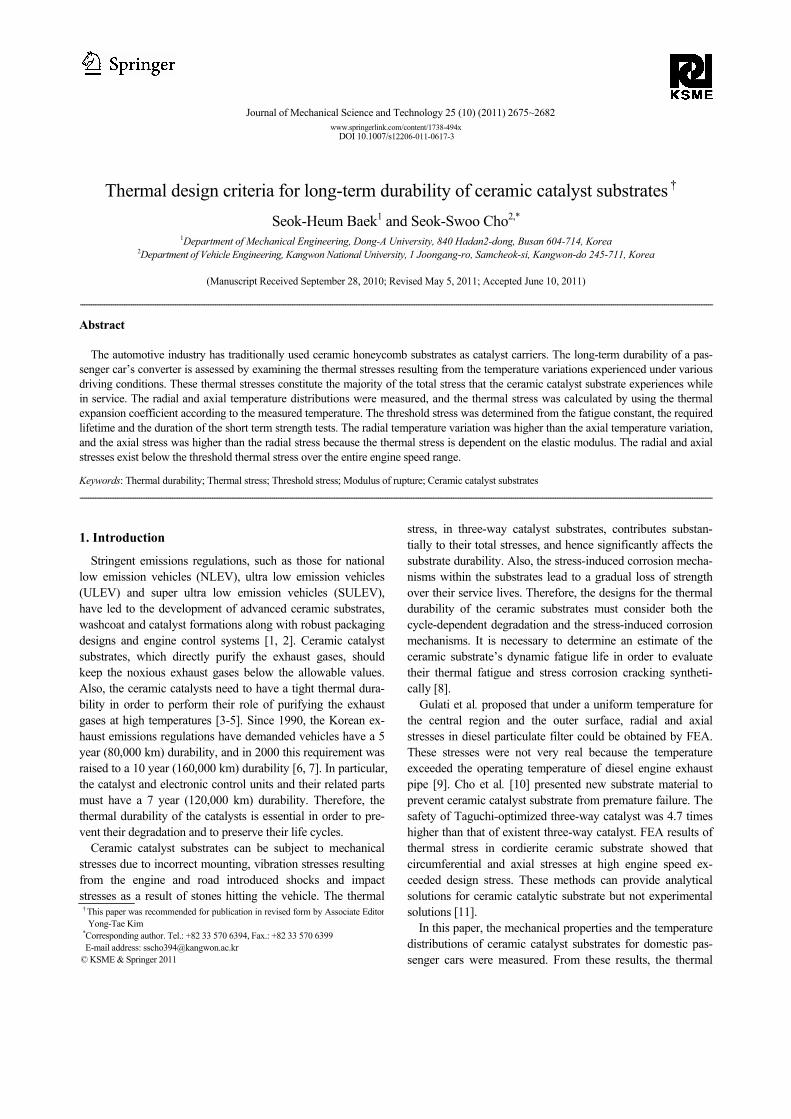
The ceramic catalyst includes a multicellular monolith body with a honeycomb structure made of cordierite and a coating consisting of theta alumina synthesized in situ on the multicel-lular monolith body. The in situ theta alumina is strongly bonded with the multicellular monolith body and comprises at least 50% by weight of the washcoat layer, and preferably greater than 90% by weight.
Fig. 1 shows the structure of a ceramic catalyst converter in a gasoline engine (engine model type: NEW SIRIUS, engine code: G4CP) and Table 1 shows the geometric properties of a square cell honeycomb substrate.
2.2 Temperature measurements
Table 2 shows the specifications of the gasoline engine used in this study and Table 3 shows the test conditions of the en-gine, in which the speed is controlled in the absence of both wind and engine torque.
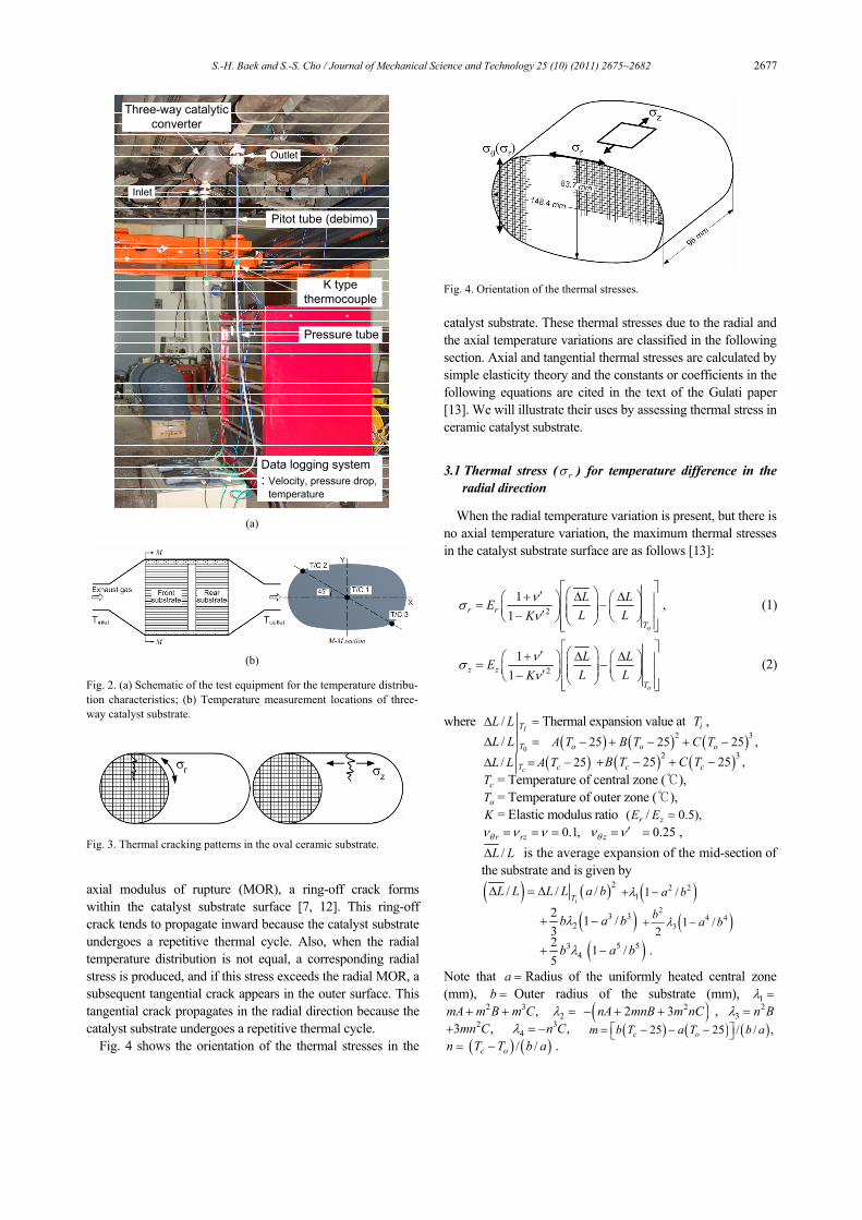
Fig. 2 shows the schematic of the test equipment used to make the temperature measurements. This setup consists of a
gasoline engine, a three-way catalyst, a temperature measure-ment system and an exhaust gas measurement system. The exhaust gas temperature is measured at the inlet and the outlet of the three-way catalyst substrates. K-type thermocouples were installed on the can of the three-way catalytic converter by using stainless steel wire with a diameter of 1 mm. We assumed that the exhaust gas flow is axially symmetric. The thermocouples are placed on the inlet and the outlet of the 1/4 catalyst substrate model, and the durability is evaluated via the steady state temperatures.
3. Thermal stress analysis
Fig. 3 shows a thermal stress analysis model within the ce-ramic substrate. Axial stress is produced when the axial tem-perature distribution is not equal. If the axial stress exceeds the
(a) Three-way catalytic converter
(b) Ceramic substrate
Fig. 1. Structure of the three-way catalytic converter.
Table 1. Geometric properties of the square cell honeycomb.
Item Specification
Manufacturer Corning Inc. (USA)
Major diameter 148.4 mm
Minor diameter 83.7 mm
Front length 96 mm
Rear length 77 mm
Cell density 62 cell/cm3
Cell pitch 1.326 mm
Channel width 1.085 mm
Wall thickness 0.241 mm
Open frontal area 75.7%
Geometric surface area 27.4 cm2/cm3
Hydraulic diameter 0.1105 cm
Total pore area 17.993 m2/g
Average pore diameter 0.0508 μm
Porosity 36.5%
Table 2. Specifications of the gasoline engine.
Item Specification
Engine type SOHC, 4-cylinder
Displacement volume 1997cc
Bore×Stroke 58 mm×88 mm
Compression ratio 8.6 : 1
Max. power 115 PS/5000 rpm
Max. torque 177 Nm/45 rpm
Firing order 1-3-4-2
Idle engine speed 750±100 rpm
Table 3. Test conditions for the thermal mapping of the oval converter.
Engine speed(rpm) 1000 1800 2700 3600 4500 5400
S.-H. Baek and S.-S. Cho / Journal of Mechanical Science and Technology 25 (10) (2011) 2675~2682 2677
axial modulus of rupture (MOR), a ring-off crack forms within the catalyst substrate surface [7, 12]. This ring-off crack tends to propagate inward because the catalyst substrate undergoes a repetitive thermal cycle. Also, when the radial temperature distribution is not equal, a corresponding radial stress is produced, and if this stress exceeds the radial MOR, a subsequent tangential crack appears in the outer surface. This tangential crack propagates in the radial direction because the catalyst substrate undergoes a repetitive thermal cycle.
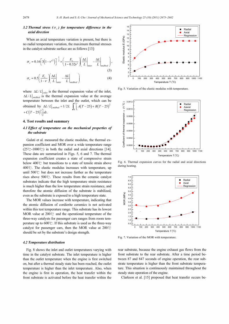
Fig. 4 shows the orientation of the thermal stresses in the
catalyst substrate. These thermal stresses due to the radial and the axial temperature variations are classified in the following section. Axial and tangential thermal stresses are calculated by simple elasticity theory and the constants or coefficients in the following equations are cited in the text of the Gulati paper [13]. We will illustrate their uses by assessing thermal stress in ceramic catalyst substrate.
3.1 Thermal stress ( rσ ) for temperature difference in the
radial direction
When the radial temperature variation is present, but there is no axial temperature variation, the maximum thermal stresses in the catalyst substrate surface are as follows [13]:
21
1o
r r
T
L LEL LK
νσν
⎡ ⎤⎛ ⎞′+ Δ Δ⎛ ⎞ ⎛ ⎞⎢ ⎥= −⎜ ⎟⎜ ⎟ ⎜ ⎟⎜ ⎟⎢ ⎥′−⎝ ⎠ ⎝ ⎠⎝ ⎠⎢ ⎥⎣ ⎦
, (1)
21
1o
z z
T
L LEL LK
νσν
⎡ ⎤⎛ ⎞′+ Δ Δ⎛ ⎞ ⎛ ⎞⎢ ⎥= −⎜ ⎟⎜ ⎟ ⎜ ⎟⎜ ⎟⎢ ⎥′−⎝ ⎠ ⎝ ⎠⎝ ⎠⎢ ⎥⎣ ⎦
(2)
where /
ITL LΔ = Thermal expansion value at iT ,
0/ TL LΔ = ( ) ( ) ( )2 325 25 25 ,o o oA T B T C T− + − + −
( )/ 25cT cL L A TΔ = − ( ) ( )2 325 25 ,c cB T C T+ − + −
cT = Temperature of central zone (℃), oT = Temperature of outer zone (℃),
K = Elastic modulus ratio ( / 0.5),r zE E = 0.1,r rzθν ν ν= = = zθν ν ′= 0.25= ,
/L LΔ is the average expansion of the mid-section of the substrate and is given by
( ) ( )2/ / /iT
L L L L a bΔ = Δ ( )2 21 1 /a bλ+ −
( )3 32
2 1 /3
b a bλ+ − ( )2
4 43 1 /
2b a bλ+ −
34
25
b λ+ ( )5 51 /a b− .
Note that a = Radius of the uniformly heated central zone (mm), b = Outer radius of the substrate (mm), 1λ =
2 3 ,mA m B m C+ + 2λ = ( )22 3nA mnB m nC− + + , 23 n Bλ =
23 ,mn C+ 34 ,n Cλ = − ( ) ( ) ( )25 25 / / ,c om b T a T b a⎡ ⎤= − − −⎣ ⎦
n = ( ) ( )/ /c oT T b a− .
Three-way catalytic converter
Data logging system: Velocity, pressure drop,
temperature
Pitot tube (debimo)
K typethermocouple
Pressure tube
Inlet
Outlet
(a)
(b) Fig. 2. (a) Schematic of the test equipment for the temperature distribu-tion characteristics; (b) Temperature measurement locations of three-way catalyst substrate.
Fig. 3. Thermal cracking patterns in the oval ceramic substrate.
Fig. 4. Orientation of the thermal stresses.
2678 S.-H. Baek and S.-S. Cho / Journal of Mechanical Science and Technology 25 (10) (2011) 2675~2682
3.2 Thermal stress ( zσ ) for temperature difference in the axial direction
When an axial temperature variation is present, but there is no radial temperature variation, the maximum thermal stresses in the catalyst substrate surface are as follows [13]:
( )1
2 20.16 3 11 0.32
zz
inlet midbed
E L LL L
σ νν
⎛ ⎞Δ Δ⎛ ⎞⎡ ⎤′= − × −⎜ ⎟⎜ ⎟⎜ ⎟⎣ ⎦ ′−⎝ ⎠⎝ ⎠,
(3)
0.51
rr
inlet midbed
E L LL L
σν
⎛ ⎞Δ Δ⎛ ⎞= −⎜ ⎟⎜ ⎟⎜ ⎟−⎝ ⎠⎝ ⎠ (4)
where / inletL LΔ is the thermal expansion value of the inlet,
/ midbedL LΔ is the thermal expansion value at the average temperature between the inlet and the outlet, which can be obtained by / 1/ 2midbedL L LΔ = ( ) ( )2
025 25
LA T B T⎡ − + −⎢⎣∫
( )325 .C T dz⎤+ − ⎥⎦
4. Test results and summary
4.1 Effect of temperature on the mechanical properties of the substrate
Gulati et al. measured the elastic modulus, the thermal ex-pansion coefficient and MOR over a wide temperature range (25℃-1000℃) in both the radial and axial directions [14]. These data are summarized in Figs. 5, 6 and 7. The thermal expansion coefficient creates a state of compressive strain below 400℃ but transitions to a state of tensile strain above 400℃. The elastic modulus increases with temperature, up until 500℃ but does not increase further as the temperature rises above 500℃. These results from the ceramic catalyst substrates indicate that the high temperature strain resistance is much higher than the low temperature strain resistance, and therefore the atomic diffusion of the substrate is stabilized, even as the substrate is exposed to a high temperature state.
The MOR values increase with temperature, indicating that the atomic diffusion of cordierite ceramics is not activated within this test temperature range. This substrate has its lowest MOR value at 200℃ and the operational temperature of the three-way catalysts for passenger cars ranges from room tem-perature up to 600℃. If this substrate is used as the three-way catalyst for passenger cars, then the MOR value at 200℃ should be set by the substrate’s design strength.
4.2 Temperature distribution
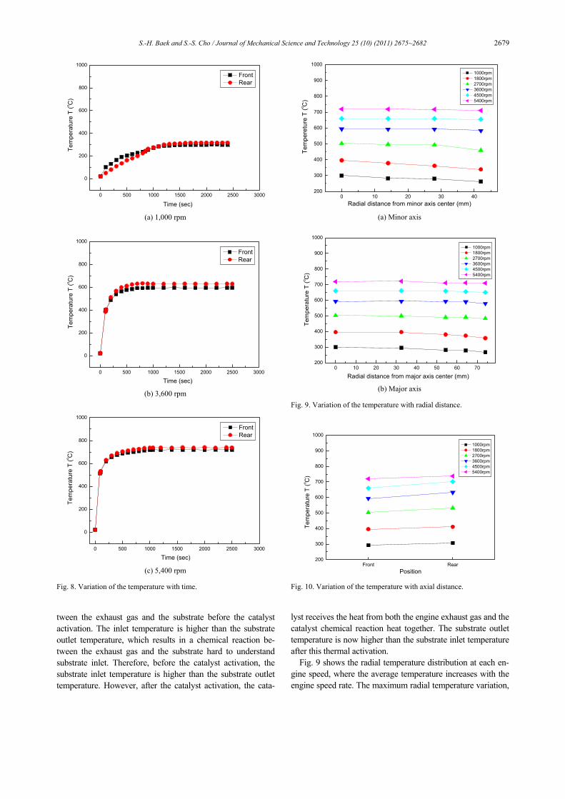
Fig. 8 shows the inlet and outlet temperatures varying with time in the catalyst substrate. The inlet temperature is higher than the outlet temperature when the engine is first switched on, but after a thermal steady state has been reached, the outlet temperature is higher than the inlet temperature. Also, when the engine is first in operation, the heat transfer within the front substrate is activated before the heat transfer within the
rear substrate, because the engine exhaust gas flows from the front substrate to the rear substrate. After a time period be-tween 87 and 847 seconds of engine operation, the rear sub-strate temperature is higher than the front substrate tempera-ture. This situation is continuously maintained throughout the steady state operation of the engine.
Clarkson et al. [15] proposed that heat transfer occurs be-
0 100 200 300 400 500 600 700 800 900 1000 11002
3
4
5
6
7
8
9
10
11
12
13
14
15
E
last
ic m
odul
us E
(GP
a)
Temperature T (oC)
Radial Axial Regression
Fig. 5. Variation of the elastic modulus with temperature.
0 100 200 300 400 500 600 700 800 900 1000 1100
0.0000
0.0002
0.0004
0.0006
0.0008
0.0010
0.0012
C
oeffi
cien
t of t
herm
al e
xpan
sion
α (
1/ o C
)
Temperature T (oC)
Radial Aaxial Regression
Fig. 6. Thermal expansion curves for the radial and axial directions during heating.
0 100 200 300 400 500 600 700 800 900 1000 1100
0.5
1.0
1.5
2.0
2.5
3.0
3.5
4.0
4.5
5.0
5.5
6.0
6.5
7.0
Temperature T (oC)
M
OR
(MPa
)
Radial Axial Regression
Fig. 7. Variation of the MOR with temperature.
S.-H. Baek and S.-S. Cho / Journal of Mechanical Science and Technology 25 (10) (2011) 2675~2682 2679
tween the exhaust gas and the substrate before the catalyst activation. The inlet temperature is higher than the substrate outlet temperature, which results in a chemical reaction be-tween the exhaust gas and the substrate hard to understand substrate inlet. Therefore, before the catalyst activation, the substrate inlet temperature is higher than the substrate outlet temperature. However, after the catalyst activation, the cata-
lyst receives the heat from both the engine exhaust gas and the catalyst chemical reaction heat together. The substrate outlet temperature is now higher than the substrate inlet temperature after this thermal activation.
Fig. 9 shows the radial temperature distribution at each en-gine speed, where the average temperature increases with the engine speed rate. The maximum radial temperature variation,
0 500 1000 1500 2000 2500 3000
0
200
400
600
800
1000Te
mpe
ratu
re T
(o C)
Time (sec)
Front Rear
(a) 1,000 rpm
0 500 1000 1500 2000 2500 3000
0
200
400
600
800
1000
Time (sec)
Tem
pera
ture
T (o C
)
Front Rear
(b) 3,600 rpm
0 500 1000 1500 2000 2500 3000
0
200
400
600
800
1000
Tem
pera
ture
T (o C
)
Time (sec)
Front Rear
(c) 5,400 rpm
Fig. 8. Variation of the temperature with time.
0 10 20 30 40200
300
400
500
600
700
800
900
1000
Tem
pere
ture
T (o C
)
Radial distance from minor axis center (mm)
1000rpm 1800rpm 2700rpm 3600rpm 4500rpm 5400rpm
(a) Minor axis
0 10 20 30 40 50 60 70200
300
400
500
600
700
800
900
1000
Te
mpe
ratu
re T
(o C)
Radial distance from major axis center (mm)
1000rpm 1800rpm 2700rpm 3600rpm 4500rpm 5400rpm
(b) Major axis
Fig. 9. Variation of the temperature with radial distance.
Front Rear200
300
400
500
600
700
800
900
1000
1000rpm 1800rpm 2700rpm 3600rpm 4500rpm 5400rpm
Tem
pera
ture
T (o C
)
Position Fig. 10. Variation of the temperature with axial distance.
2680 S.-H. Baek and S.-S. Cho / Journal of Mechanical Science and Technology 25 (10) (2011) 2675~2682
56.8℃/m, occurs in the minor axis direction at an engine speed of 1,800 rpm. The temperature variation for engine speeds greater than 1,800 rpm is lower than the value obtained at 1,800 rpm. The engine does not receive any wind flow dur-ing the tests; therefore, there is no forced convection from the air on the three-way catalyst.
Fig. 10 shows the axial temperature for different engine speeds. The maximum axial temperature variation, 41.7℃/m, occurs at an engine speed of 4,500 rpm. This maximum axial temperature variation is lower than the maximum radial tem-perature variation.
4.3 Thermal durability
Fig. 11 shows the schematic variation of the thermal stress in the peripheral region during the full load and the idle por-tions of the engine’s operational cycle. The catalytic converter experiences stresses during its service, whose magnitude and location vary with the engine load. If the magnitudes of these stresses exceed the allowable thresholds, fatigue may set in and weaken the ceramic substrate as a result of the slow propagation of the surface flows. The structural ceramic parts will experience stress corrosion cracking, and their strength decreases gradually with time if they are exposed to water or other specific chemical substances. This concept cannot be explained by the existing fatigue theory, but the safety of the ceramic substrate is estimated by the power law model of fatigue [16]. This is mathematically given by
( )
1
1
ns
thl
tMORt n
σ⎡ ⎤
= ⎢ ⎥+⎢ ⎥⎣ ⎦
(5)
where thσ denotes the allowable long-term stress, MOR de-notes the short term strength from the 4-point bending tests,
st is the duration of the short term strength test, lt is the re-quired lifetime and n is the fatigue constant of the cordierite ceramics used.
Gulati et al. [17] proposed a fatigue constant of cordierite
ceramics of 24, but this is the mean value from several tests. The fatigue constant uses the minimum value of 20.7 from 4-point bending tests in order to secure the stability of the ce-ramic substrate. The threshold thermal stress is determined by substituting the fatigue constant of 20.7 into Eq. (5). Recalling that the typical life warranty for the converter package in a passenger car is 120,000 km, and assuming an average vehicle speed of 80 km/h, a value is obtained for lt of 1,500 hrs or 5,400,000 seconds. The threshold thermal stress thσ is deter-mined by substituting st = 30 seconds, n = 20.7 and lt = 5,400,000 seconds into Eq. (5) and gives the following result:
0.48th MORσ ≤ . (6)
Thermal fatigue damage is produced in the ceramic sub-
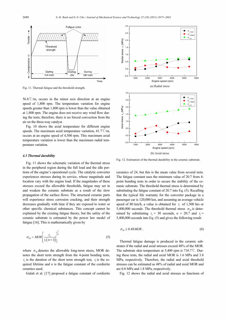
strates if the radial and axial stresses exceed 48% of the MOR. The substrate skin temperature at 5,400 rpm is 710.7℃. Dur-ing these tests, the radial and axial MOR is 1.6 MPa and 3.8 MPa, respectively. Therefore, the radial and axial threshold stresses can be estimated as 48% of radial and axial MOR and are 0.8 MPa and 1.8 MPa, respectively.
Fig. 12 shows the radial and axial stresses as functions of
Fig. 11. Thermal fatigue and the threshold strength.
1000 2000 3000 4000 5000 6000-0.5
0.0
0.5
1.0
1.5
2.0
2.5
3.0
Rad
ial s
tress
σr (
MP
a)
Engine speed (rpm)
σr, Axial σr, Radial σr, th
(a) Radial stress
1000 2000 3000 4000 5000 6000-0.5
0.0
0.5
1.0
1.5
2.0
2.5
3.0
A
xial
stre
ss σ
z (M
Pa)
Engine speed (rpm)
σz, Axial σz, Radial σz, th
(b) Axial stress
Fig. 12. Estimation of the thermal durability in the ceramic substrate.
S.-H. Baek and S.-S. Cho / Journal of Mechanical Science and Technology 25 (10) (2011) 2675~2682 2681
the engine speed. The threshold stresses at each engine speed are also shown, and the axial stress is higher than the radial stress. From Figs. 5, 9, 10 and 12, the thermal stress has a greater dependence on the direction of the elastic modulus than the direction of the temperature variation. However, the radial stress for engine speeds greater than 4,500 rpm ap-proaches 86% of the threshold stress. If the substrate is esti-mated by the thermal stress model in this study, then the radial and axial stress must be considered at the same time, because the radial and axial temperature distributions are not the same.
5. Conclusions
The thermal durability of the ceramic substrate for a three-way catalytic converter has been evaluated with the dynamic fatigue life model. The results of this evaluation are as fol-lows:
(1) The radial temperature variation was higher than the ax-ial temperature variation in the substrate.
(2) The radial and axial threshold stresses of ceramic cata-lyst substrate are estimated as 48% of radial and axial MOR.
(3) The thermal stress had a higher dependence on the di-rection of the elastic modulus than on the direction of the tem-perature variation. The axial stress was higher than the radial stress.
(4) The radial and axial stress did not exceed the threshold stress for all of the tested engine speeds. At speeds greater than 4,500 rpm, the radial stress approached 86% of the threshold stress.
(5) The substrate must be estimated by the radial and axial stress at the same time because the radial and axial tempera-ture distributions are not the same.
Nomenclature------------------------------------------------------------------------
NLEV : National low emission vehicles ULEV : Ultra low emission vehicles SULEV : Super ultra low emission vehicles MOR : Modulus of rupture
Notation
rσ : Radial stress zσ : Axial stress
cT : Temperature of central zone oT : Temperature of outer zone
K : Elastic modulus ratio ijν : Poisson’s ratio
/ inletL LΔ : Thermal expansion value of the inlet / midbedL LΔ : Thermal expansion value at the average tem-
perature between the inlet and the outlet thσ : Allowable long-term stress
st : Duration of the short term strength test lt : Required lifetime
n : Fatigue constant
References
[1] M. Rempei, Introduction to environment technology in automobile, Grand-Prix Publication, Tokyo (2002) 40-68.
[2] T. Shamim, H. Shen, S. Sengupta, S. Son and A. A. Adamczyk, A comprehensive model to predict three-way catalytic converter performance, ASME J Eng Gas Turbines Power, 124 (2) (2002) 421-28.
[3] G. N. Pontikakis, G. S. Konstantas and A. M. Stamatelos, Three-way catalytic converter modeling as a modern engi-neering design tool, ASME J Eng Gas Turbines Power, 126 (4) (2004) 906-23.
[4] D. N. Tsinoglou and G. C. Koltsakis, Influence of pulsating flow on close-coupled catalyst performance, ASME J Eng Gas Turbines Power, 127 (3) (2005) 676-82.
[5] E. M. R. Arantes and M. A. F. Medeiros, Optimization of the flow in the catalytic converter of internal combustion en-gines by means of screens, ASME J Eng Gas Turbines Power, 130 (5) (2008) 054504:1-5.
[6] G. N. Coppage and S. R. Bell, Use of an electrically heated catalyst to reduce cold-start emissions in a Bi-fuel spark ig-nited engine, ASME J Eng Gas Turbines Power, 123 (1) (2001) 125-31.
[7] S. H. Baek, S. S. Cho, S. G. Shin and W. S. Joo, Size effect on the modulus of rupture in automotive ceramic monolithic substrate using optimization and response surface method, Trans of the KSME(A) (in Korean), 30 (11) (2006) 1392-400.
[8] J. D. Helfinstine, Adding static and dynamic fatigue effects directly to the Weibull distribution, J Am Ceram Soc, 63 (1-2) (1980) 113.
[9] S. T. Gulati, Long-term durability of ceramic honeycombs for automotive emissions control, SAE paper (1985) No. 850130.
[10] D. W. Lee and S. S. Cho, Premature failure prevention of three-way catalyst substrate using DOE, Trans of the KSPE (in Korean), 27 (7) (2010) 101-108.
[11] S. H. Baek and S. S. Cho, Comparison of experimental and numerical analysis for durability design criteria in ceramic catalyst substrate, Trans of the KSPE (in Korean), 27 (9) (2010) 58-66.
[12] Z. P. Bažant, Y. Zhou, D. Novák and I. M. Daniel, Size effect on flexural strength of fiber-composite laminates, ASME J Eng Mater Technology, 126 (1) (2004) 29-37.
[13] S. T. Gulati, Thermal stresses in ceramic wall flow diesel filters, SAE Paper (1983) No. 830079.
[14] S. T. Gulati, L. E. Hampton and D. W. Lambert, Thermal shock resistance of advanced ceramic catalysts for close-coupled application, SAE Paper (2002) No. 2002-01-0738.
[15] R. J. Clarkson, S. F. Benjamin, T. S. Jasper and N. S. Girls, An integrated computational model for the optimisation of monolith catalytic converters, SAE Paper (1993) No. 931071.
[16] J. D. Helfinstine and S. T. Gulati, High temperature fatigue in ceramic honeycomb catalyst supports, SAE Paper (1985) No. 852100.
[17] S. T. Gulati, B. Williamson, J. Nunan and K. Anderson,

2682 S.-H. Baek and S.-S. Cho / Journal of Mechanical Science and Technology 25 (10) (2011) 2675~2682
Fatigue and performance data for advanced thin wall ce-ramic catalysts, SAE Tech Paper (1998) No. 980670.
Seok Heum Baek received his B.S. in Mechanical Engineering from Dong-A University, Korea, in 2001. He then went on to receive his M.S. and Ph.D degrees from Dong-A University, Korea, in 2003 and 2010, respectively. Dr. Baek is cur-rently a BK21 Post-Doctoral Fellow at the School of Mechanical Engineering at
Dong-A University in Busan, Korea. His research interests cover the area of metamodeling, multidisciplinary modeling and optimization methods, and fatigue fracture analysis.
Seok Swoo Cho received his B.S. in Mechanical Engineering from Dong-A University, Korea, in 1991. He then went on to receive his M.S. from Dong-A University in 1993 and Ph.D from Dong-A University in 1997. Dr. Cho is currently a Professor at the School of Vehicle Engineering at Kangwon Na-
tional University in Gangwon-do, Korea. His research inter-ests include structural failure analysis, fatigue and fracture mechanics.


![Open Research Onlineoro.open.ac.uk/46016/1/[C52] DH High temperature... · the modelled peak stress level on the ceramic surface at the metal-ceramic interface for DBA and DBC substrates](https://img.pdfslide.us/doc/110x75/60335d3fd0813c74112534f2/open-research-c52-dh-high-temperature-the-modelled-peak-stress-level-on-the.jpg)