Embed Size (px)
Citation preview
Thermal Considerations with TissueElectroporation
Timothy J. O’Brien, Christopher B. Arena, and Rafael V. Davalos
AbstractElectroporation is an energy-directed therapeutic that relies on the application ofpulsed electric fields to increase the transmembrane potential of a cell above acritical value, destabilizing the lipid bilayer of the cellular membrane and increas-ing cell tissue permeability. For years, researchers have used this phenomenon toassist the transport of macromolecules that typically are unable to penetrate thecell membrane with the intent of avoiding cell necrosis or irreversible electropo-ration. More recently, however, irreversible electroporation is proven to be asuccessful option for the treatment of cancer. More specifically, the proper tuningof pulse parameters has allowed for a nonthermally damaging targeted treatmentof unresectable tumors. Pretreatment planning is implemented to moderate theassociated thermal effects with the electroporation of biological tissue. However,the overall size and volume of the ablation is a function of the electrode geometry,electrode spacing, voltage amplitude, pulse frequency, and pulse repetition. Manyresearchers are motivated to maintain tissue temperature below a thermallydamaging threshold while expanding the range of treatment and increasingablation dimensions. Thermal mitigation strategies, including the installation ofactive cooling channels and phase change materials within electrodes, have thepotential to allow the delivery of more energy to the tissue at a thermally safetemperature, ultimately resulting in larger ablation volumes.
T.J. O’Brien • R.V. Davalos (*)Bioelectromechanical Systems Laboratory, ICTAS Center for Engineered Health, Department ofBiomedical Engineering and Mechanics, Virginia Tech - Wake Forest School of BiomedicalEngineering and Sciences, Blacksburg, VA, USAe-mail: [email protected]; [email protected]
C.B. ArenaLaboratory for Therapeutic Directed Energy, Department of Physics, Elon University,Elon, NC, USAe-mail: [email protected]
# Springer International Publishing AG 2017F.A. Kulacki (ed.), Handbook of Thermal Science and Engineering,DOI 10.1007/978-3-319-32003-8_68-1
1
Contents1 Introduction . . . . . . . . . . . . . . . . . . . . . . . . . . . . . . . . . . . . . . . . . . . . . . . . . . . . . . . . . . . . . . . . . . . . . . . . . . . . . . . . . . . 22 Theoretical Considerations of Electroporation . . . . . . . . . . . . . . . . . . . . . . . . . . . . . . . . . . . . . . . . . . . . . . . 4
2.1 Determining the Electric Field Distribution . . . . . . . . . . . . . . . . . . . . . . . . . . . . . . . . . . . . . . . . . . . 42.2 Boundary Conditions and Initial Conditions . . . . . . . . . . . . . . . . . . . . . . . . . . . . . . . . . . . . . . . . . . 62.3 Joule Heating . . . . . . . . . . . . . . . . . . . . . . . . . . . . . . . . . . . . . . . . . . . . . . . . . . . . . . . . . . . . . . . . . . . . . . . . . . . 62.4 Dynamic Electrical Properties . . . . . . . . . . . . . . . . . . . . . . . . . . . . . . . . . . . . . . . . . . . . . . . . . . . . . . . . . . 8
3 Determining the Thermal Distribution . . . . . . . . . . . . . . . . . . . . . . . . . . . . . . . . . . . . . . . . . . . . . . . . . . . . . . . 83.1 Derivation of the Heat Diffusion Equation . . . . . . . . . . . . . . . . . . . . . . . . . . . . . . . . . . . . . . . . . . . . 83.2 Pennes Bioheat Equation . . . . . . . . . . . . . . . . . . . . . . . . . . . . . . . . . . . . . . . . . . . . . . . . . . . . . . . . . . . . . . . 103.3 Dynamic Thermal Properties . . . . . . . . . . . . . . . . . . . . . . . . . . . . . . . . . . . . . . . . . . . . . . . . . . . . . . . . . . . 12
4 Assessing Thermal Damage . . . . . . . . . . . . . . . . . . . . . . . . . . . . . . . . . . . . . . . . . . . . . . . . . . . . . . . . . . . . . . . . . . 124.1 Damage Equation . . . . . . . . . . . . . . . . . . . . . . . . . . . . . . . . . . . . . . . . . . . . . . . . . . . . . . . . . . . . . . . . . . . . . . . 144.2 Thermal Dose . . . . . . . . . . . . . . . . . . . . . . . . . . . . . . . . . . . . . . . . . . . . . . . . . . . . . . . . . . . . . . . . . . . . . . . . . . . 15
5 Numerical Modeling of Electroporation . . . . . . . . . . . . . . . . . . . . . . . . . . . . . . . . . . . . . . . . . . . . . . . . . . . . . 155.1 Special Tissue Considerations . . . . . . . . . . . . . . . . . . . . . . . . . . . . . . . . . . . . . . . . . . . . . . . . . . . . . . . . . . 17
6 Thermal Mitigation Strategies . . . . . . . . . . . . . . . . . . . . . . . . . . . . . . . . . . . . . . . . . . . . . . . . . . . . . . . . . . . . . . . . 206.1 Active Cooling . . . . . . . . . . . . . . . . . . . . . . . . . . . . . . . . . . . . . . . . . . . . . . . . . . . . . . . . . . . . . . . . . . . . . . . . . . 206.2 Phase Change Material (PCM) . . . . . . . . . . . . . . . . . . . . . . . . . . . . . . . . . . . . . . . . . . . . . . . . . . . . . . . . . 24
7 Concluding Remarks . . . . . . . . . . . . . . . . . . . . . . . . . . . . . . . . . . . . . . . . . . . . . . . . . . . . . . . . . . . . . . . . . . . . . . . . . 268 Cross-References . . . . . . . . . . . . . . . . . . . . . . . . . . . . . . . . . . . . . . . . . . . . . . . . . . . . . . . . . . . . . . . . . . . . . . . . . . . . . 27References . . . . . . . . . . . . . . . . . . . . . . . . . . . . . . . . . . . . . . . . . . . . . . . . . . . . . . . . . . . . . . . . . . . . . . . . . . . . . . . . . . . . . . . . 27
1 Introduction
The cell membrane acts as a selectively permeable barrier, separating and protectingthe interior of a cell from its external environment while also selectively allowing thetransport of ions and molecules necessary for vital function. This semipermeablestructure fundamentally consists of a lipid bilayer and the addition of some proteins.A number of techniques have been developed to penetrate the cell membrane in aneffort to study the selective permeability, examine the intercellular biophysicalprocesses, introduce foreign molecules to the cytosol, and much more. One methodthat has gained a lot of attention within the past 66 years relies on the use of electricalfields to induce cell permeability within a specific region of tissue.
Electroporation is an energy-based therapy motivated through the generation ofbrief (nano- to microsecond) pulsed electric fields (PEF) with amplitudes on theorder of hundreds to thousands of volts per centimeter. These PEFs induce a buildupof charge across the cell membrane, known as the transmembrane potential (TMP),and ultimately lead to the temporary permeabilization of the lipid bilayer. As theTMP is increased, structural defects within the lipid bilayer occur more frequently,increasing the permeability to ions and macromolecules as well as the overallconductivity of the tissue. Electroporation occurs once the TMP exceeds approxi-mately 0.5–1 V, well above the normal “resting potential” (~0.07 V) of a healthy cell(Weaver 1995; Davalos et al. 2010). Well-developed theory has suggested that thedefects within the cell membrane take the form of nanoscale pores (Abidor et al.1979; Weaver 1994). However, direct evidence to support this theory, such as real-
2 T.J. O’Brien et al.
time imaging or direct visualization of pore formation, is nonexistent. Consequently,the biophysical mechanisms behind membrane permeabilization are still highlydebated.
Soon after the discovery of these structural defects in the late 1950s (Jiang et al.2015), electroporation was used to facilitate the transport of molecules across cellmembranes without any direct compromise to the viability of the cell (Neumannet al. 1982; Davalos and Rubinsky 2008). This process, known as reversibleelectroporation, has become an important tool in the fields of biomedical engineeringand medicine through its ability to allow the passage of macromolecules thattypically are unable to penetrate the cell membrane. Reversible electroporation hassince been used to transport various chemotherapeutics beyond the cell membrane(Granot and Rubinsky 2009) to treat varying forms of cancer by way of electro-chemotherapy (ECT) (D Miklavcic et al. 2014; Belehradek et al. 1993; Cadossi et al.2014; Pavliha et al. 2012; Domenge et al. 1996; Cemazar et al. 2008), as well as thetransport of specific genes to tissue (electrogenetherapy, EGT) (Gehl 2003; Golzioet al. 2007; Hanna et al. 2001; Li et al. 2002; Neumann et al. 1982). Additionally,when combined with dielectrophoresis, cells demonstrated indications of fusion(electrofusion), leading to many advances in tissue engineering (Gascoyne 2002and Glaser et al. 1988). Further manipulation of the electrical pulse parametersgenerated irreversible electroporation (IRE), a phenomena which results in perma-nent membrane damage and ultimately cell death.
Originally perceived as a negative consequence associated with electroporation,Davalos et al. showed that IRE could be harnessed and used as a stand-alone ablationmodality. While it is well known that every electrical field, including a fieldgenerated from IRE, produces a thermal effect, with the proper tuning of theelectrical parameters, irreversible electroporation can be effectively used as a focalablation therapy with minimal influence of temperature (Davalos et al. 2005). Thisparticular study demonstrated that the use of electroporation had the ability todestroy undesirable tissue in a similar fashion as existing focal thermal therapies,such as radiofrequency ablation and cryosurgery, without significant thermal effects.Additionally, the study established that IRE has the potential to reduce the overalltreatment time, mitigate any consequential thermal effects from overtreatment,promote the preservation of sensitive structures (major nerves, blood vessel archi-tecture, etc.), and eliminate any convective effects due to local blood perfusion fromaffecting treatment outcome (Jiang et al. 2015). These findings seized the attention ofthe scientific community leading to an extensive variety of cell (Rubinsky et al.2008; Bao et al. 2010; Shafiee et al. 2009), organ (Ellis et al. 2011; Tracy et al. 2011),and animal (Guo et al. 2010) models to characterize the potential of IRE as a meansof cancer treatment.
Pretreatment plans are often employed clinically to help guide the procedure(Pavliha et al. 2012; Garcia et al. 2009, 2010, 2011; Damijan Miklavcic et al. 2010;Kos et al. 2010). The combination of medical imaging and computational modelingof the PEFs allows for patient-specific treatment plans. Ultimately, the parametersand protocols for tissue electroporation are designed to limit Joule heating. Thenumber of pulses, pulse duration, pulse amplitude, and pulse repetition rate are all
Thermal Considerations with Tissue Electroporation 3
selectively manipulated to prompt electroporation while effectively maintaining thetissue temperature below a thermally damaging threshold. However, the design of anelectric field that simultaneously maps the entire region of interest for a singletreatment and avoids undesirable thermal effects can be challenging when treatinglarger or irregularly shaped volumes of tissue (Arena et al. 2013).
Thermal mitigation strategies are currently being explored to help safely push thebounds of IRE. While active cooling methods are at the forefront of this investiga-tion (Wandel et al. 2016), an alternative strategy under investigation examination isthe use of phase change material (PCM) within varying electrode designs. Primarily,PCM has been utilized to protect temperature-sensitive substances/products duringtransport (Mondieig et al. 2003), within clothing to protect the human body fromextreme environments (Shim et al. 2001), as well as within contrast agents for imageenhancement within the biomedical field (Sheeran et al. 2012). Beyond the biomed-ical field, PCM is being implemented in the thermal protection of electronic devices(Fok et al. 2010; Ge and Liu 2012; Mesalhy et al. 2006), green energy storage(Sharma et al. 2009; Prakash et al. 1985), and building temperature regulation(Roman et al. 2016; Karlessi et al. 2011; Osterman et al. 2012).
The primary goal of this chapter is to provide readers with the tools to understandthe biothermal effects associated with irreversible electroporation. To this end, anoverview of the governing equations and fundamental theory of electroporation thatis used to determine the distribution of the electric fields is presented. Then adescription of the heat diffusion equation and Pennes bioheat equation in relationto the electroporation of biological tissue is given. This is followed by an assessmentof the thermal damage from a typical electroporation treatment in tissue. Subse-quently, the numerical models presented throughout the chapter are summarized andpresented for two clinically relevant electrode geometries in both homogeneous andheterogeneous tissues. Lastly, the state-of-the-art temperature mitigation strategies tofurther expand the bounds and applications of irreversible electroporation aremodeled and discussed in the final section.
2 Theoretical Considerations of Electroporation
2.1 Determining the Electric Field Distribution
Maxwell’s equations provide the mathematical foundation for describing electro-magnetism. Focusing on Faraday’s law of induction and Ampère’s law, the interac-tion between electric fields and cell membranes can be described:
∇� E ¼ � @B
@t(1)
∇�H ¼ Jþ @D
@t(2)
4 T.J. O’Brien et al.
where D is the electric flux density vector, B is the magnetic flux density vector, E isthe electric field vector, H is the magnetic field vector, and J is the current densityvector. The electric flux density (D) and current density (J) can be further defined as
D ¼ eE (3)
J ¼ σE (4)
where e is the dielectric permittivity and σ is the conductivity of a medium. If theelectric energy density is much greater than the magnetic energy density, theelectroquasistatic approximation can be applied. As a result of this approximation,the electromagnetic dynamics can be neglected, specifically magnetic induction,such that Eq. 1 becomes
∇� E ¼ 0 (5)
which allows the electric field (E) to be expressed solely in terms of the electricpotential (Φ).
E ¼ �∇Φ (6)
The combination of Eqs. 2, 3, 4, and 6 yields
∇�H ¼ �σ∇Φ� e@∇Φ@t
(7)
Due to the electroquasistatic approximation, the magnetic field is not essential tothe displacement of electrical charge. Thus, taking the divergence of both sides of theequation and simplifying to a steady-state form, the equation for electric potentialdistribution is described as
0 ¼ �∇ � σ∇Φð Þ (8)
Equation 8 can be solved analytically via the separation of variables or numeri-cally via the use of a finite-element modeling software. Numerical modeling is apowerful tool that can be used to mathematically approximate physical processeswithin a given system defined by its geometry and physical material properties (i.e.,tissue). These numerical simulations provide insight to the response of the modeledsystem to varying stimuli represented by boundary conditions, initial conditions,and/ or potentially a forcing function depending upon the application. However, amathematical model is never fully defined or solvable until an appropriate set ofboundary conditions, initial conditions, and tissue properties are specified.
Thermal Considerations with Tissue Electroporation 5
2.2 Boundary Conditions and Initial Conditions
To accurately model the irreversible electroporation of a tissue, one must considerboth the electrical and the thermal boundary conditions. Typically, two monopolarelectrodes are represented with a fixed boundary condition, with one electrode actingas the source (Φ1) and the other as the sink (Φ2), where Vo is the applied voltage.Currently, the most widely used IRE electrode geometry for soft tissue and tumorablation is the parallel needle electrode geometry (monopolar probes). For theparallel monopolar electrode geometry, one probe acts as the source, while theother acts as a sink. The remaining tissue boundaries are treated as electricallyinsulating. Equation 9 displays the electrical boundary conditions:
Φsource ¼ Vo
Φsink ¼ 0
@Φ@n
¼ 0 (9)
Although several thermal boundary conditions can be employed to study the heatexchange between the electrodes, the initial temperature of the electrodes and tissuewere set to the physiologic tissue temperature of 310.15 K (37 �C). Further, the tissueboundaries were defined as adiabatic at the edge of the system domain to illustratethe maximum temperature increase within the tissue model. Equation 10 specifiesthe initial temperatures of the electrodes and tissue as well as the thermal boundaryconditions of the tissue.
T0 ¼ 310:15K@T
@n¼ 0 (10)
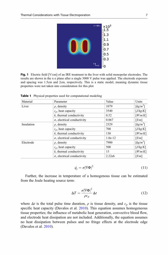
Figure 1 illustrates the resulting electric field for the irreversible electroporationof a section of liver tissue. Here, a single pulse was applied at a voltage potential(Φsource) of 3000 V and a pulse duration of 100 μs using two parallel, cylindricalelectrodes, also known as the monopolar probe geometry. The electrical and thermalboundary conditions as well as the initial conditions were set as described in Eqs. 9and 10 (surrounding tissue boundaries were electrically insulating, adiabatic). Thenumerical simulations described here and all subsequent sections were performedusing COMSOL Multiphysics 5.2 (Stockholm, Sweden). Further, the physicalproperties used in the model are provided in Table 1.
2.3 Joule Heating
Thermal energy is generated when electrical current travels through a resistivematerial. This phenomenon is known as Joule heating and is defined as the heatgeneration rate per unit volume caused by an electric field. Solving the equation forelectrical potential distribution associated with an electrical pulse (Eq. 8) yields theJoule heating source term:
6 T.J. O’Brien et al.
_qj ¼ σ ∇Φj j2 (11)
Further, the increase in temperature of a homogenous tissue can be estimatedfrom the Joule heating source term:
ΔT ¼ σ ∇Φj j2ρcp
Δt (12)
where Δt is the total pulse time duration, ρ is tissue density, and cp is the tissuespecific heat capacity (Davalos et al. 2010). This equation assumes homogeneoustissue properties; the influence of metabolic heat generation, convective blood flow,and electrode heat dissipation are not included. Additionally, the equation assumesno heat dissipation between pulses and no fringe effects at the electrode edge(Davalos et al. 2010).
Fig. 1 Electric field [V/cm] of an IRE treatment in the liver with solid monopolar electrodes. Theresults are shown in the x-z plane after a single 3000 V pulse was applied. The electrode exposureand spacing was 1.5cm and 2cm, respectively. This is a static model, meaning dynamic tissueproperties were not taken into consideration for this plot
Table 1 Physical properties used for computational modeling
Material Parameter Value Units
Liver ρ, density 1079 [kg/m3]
cp, heat capacity 3540 [J/kg/K]
k, thermal conductivity 0.52 [W/m/K]
σ, electrical conductivity 0.067 [S/m]
Insulation ρ, density 2329 [kg/m3]
cp, heat capacity 700 [J/kg/K]
k, thermal conductivity 130 [W/m/K]
σ, electrical conductivity 1.0e-12 [S/m]
Electrode ρ, density 7900 [kg/m3]
cp, heat capacity 500 [J/kg/K]
k, thermal conductivity 15 [W/m/K]
σ, electrical conductivity 2.22e6 [S/m]
Thermal Considerations with Tissue Electroporation 7
2.4 Dynamic Electrical Properties
The cell membrane serves as a barrier across which chemical and electrical potentialgradients are established. When a cell is exposed to an electric field, the membranebecomes either temporarily or permanently permeable, depending on the strength ofthe electric field. This enables the free passage of molecules typically unable topermeate across the cell membrane. Consequently, the bulk tissue electrical proper-ties are affected by the increase in extracellular conductivity and the development ofelectrical shunts across the cell body, allowing the fluent passage of current. The bulktissue electrical conductivity can be approximated from an empirically determinedequation:
σ E½ � ¼ σmax � σ0
1þ D e�E�A
B
þ σ0 (13)
where σmax is the electrical conductivity when the tissue is maximally permeabilized,σo is the initial electrical conductivity of the nonpermeabilized tissue, D a issigmoidal function parameter, E is the electric field vector, and lastly both A andB are curve-fitting terms that depend on reversible electrical field threshold, E0, andirreversible electroporation threshold, E1. Parameters A and B can be expressed as
A ¼ E0 � E1
2(14)
B ¼ E1 � E0
C(15)
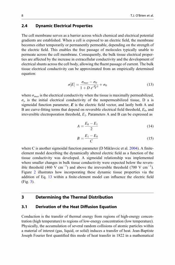
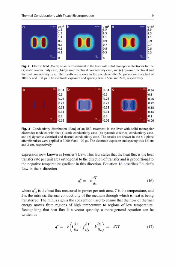
where C is another sigmoidal function parameter (D Miklavcic et al. 2004). A finite-element model describing the dynamically altered electric field as a function of thetissue conductivity was developed. A sigmoidal relationship was implementedwhere smaller changes in bulk tissue conductivity were expected below the revers-ible threshold (460 V cm�1) and above the irreversible threshold (700 V cm�1).Figure 2 illustrates how incorporating these dynamic tissue properties via theaddition of Eq. 13 within a finite-element model can influence the electric field(Fig. 3).
3 Determining the Thermal Distribution
3.1 Derivation of the Heat Diffusion Equation
Conduction is the transfer of thermal energy from regions of high-energy concen-tration (high temperature) to regions of low-energy concentration (low temperature).Physically, the accumulation of several random collisions of atomic particles withina material of interest (gas, liquid, or solid) induces a transfer of heat. Jean-BaptisteJoseph Fourier first quantified this mode of heat transfer in 1822 in a mathematical
8 T.J. O’Brien et al.
expression now known as Fourier’s Law. This law states that the heat flux is the heattransfer rate per unit area orthogonal to the direction of transfer and is proportional tothe negative temperature gradient in this direction. Equation 16 describes Fourier’sLaw in the x-direction
q00x ¼ �kdT
dx(16)
where q00x is the heat flux measured in power per unit area, T is the temperature, andk is the intrinsic thermal conductivity of the medium through which is heat is beingtransferred. The minus sign is the convention used to ensure that the flow of thermalenergy moves from regions of high temperature to regions of low temperature.Recognizing that heat flux is a vector quantity, a more general equation can bewritten as
q00 ¼ �k i@T
@xþ j
@T
@yþ k
@T
@z
� �¼ �k∇T (17)
Fig. 2 Electric field [V/cm] of an IRE treatment in the liver with solid monopolar electrodes for the(a) static conductivity case, (b) dynamic electrical conductivity case, and (c) dynamic electrical andthermal conductivity case. The results are shown in the z-x plane after 60 pulses were applied at3000 V and 100 μs. The electrode exposure and spacing was 1.5cm and 2cm, respectively
Fig. 3 Conductivity distribution [S/m] of an IRE treatment in the liver with solid monopolarelectrodes modeled with the (a) static conductivity case, (b) dynamic electrical conductivity case,and (c) dynamic electrical and thermal conductivity case. The results are shown in the x-z planeafter 60 pulses were applied at 3000 Vand 100 μs. The electrode exposure and spacing was 1.5 cmand 2 cm, respectively
Thermal Considerations with Tissue Electroporation 9
To determine the temperature distribution, the appropriate energy balance for aninfinitesimal control volume within the material of interest (i.e., tissue) is required.Fundamentally, the rate of energy entering the control volume minus the rate ofenergy leaving plus the rate of energy generated must equal the rate of energy storedat every point within the material of interest. Assuming a Cartesian coordinatesystem, the energy balance equation can be depicted as
ρcp@T
@tdxdydz ¼ q00x � q00xþdx
� �dydzþ q00y � q00yþdy
� �dxdzþ q00z � q00zþdz
� �dxdy
þ _q dxdydz (18)
where ρ is the tissue density, cp is the specific heat of the tissue, and _q is the heatgenerated per unit volume. Dividing by the volume (dxdydz), Eq. 16 can be rewrittenas
ρcp@T
@t¼ � @q00x
@x� @q00y
@y� @q00z
@zþ _q (19)
Substitution of the generalized equation for Fourier’s Law (Eq. 13) yields the heatdiffusion equation:
ρcp@T
@t¼ @
@xk@T
@x
� �þ @
@yk@T
@y
� �þ @
@zk@T
@z
� �þ _q
� or�ρcp
@T
@t¼ ∇ � k∇Tð Þ þ _q
(20)
Given the proper boundary conditions and initial conditions, the heat diffusionequation enables the prediction of the temperature distribution for a given volume ofmaterial (Fig. 4).
3.2 Pennes Bioheat Equation
The topic of heat transfer within biological tissue is slightly more complex than theheat transfer within conventional engineering materials when accounting for meta-bolic heat generation and the exchange of thermal energy from flowing blood and thesurrounding tissue. In 1948, Harry H. Pennes modified the heat diffusion equation toaccount for these two biological phenomena (Pennes 1948). The Pennes bioheatequation, although known to have limitations, is often used to solve heat transferproblems within the body. This model assumes homogenous tissue properties,uniform metabolic heat generation, and a proportionality between the convectiveheat transfer entering and leaving the tissue.
10 T.J. O’Brien et al.
ρcp@T
@t¼ ∇ � k∇Tð Þ � ωbcb T � Tað Þ þ _qm (21)
where ρ is the density of the tissue, cp is the specific heat of the tissue, k is the thermalconductivity, ωb is the blood perfusion, cb is the specific heat of the blood, Ta is thearterial blood temperature, and _qm is the metabolic heat generation. The heatgenerated from an irreversible electroporation treatment can be calculated by mod-ifying the Pennes bioheat equation to include the Joule heating source term, thesolution to the Laplace equation for electric potential distribution (Eq. 11):
ρcp@T
@t¼ ∇ � k∇Tð Þ � ωbcb T � Tað Þ þ _qm þ _qj (22)
It is important to note that not all finite-element methods are capable of handlingthe metabolic heat generation and blood perfusion terms included in Eq. 20. How-ever, a simple variable substitution may be applied to surpass this constraint (Eddand Davalos 2007; Davalos et al. 2003). Let
T � Ta ¼ θe�ωbcbρcp
t(23)
The transformation becomes
ρcp@θ
@te�ωbcbρcp
t � ρcpωbcbρcp
e�ωbcbρcp
t ¼ ∇ � k∇θð Þe�ωbcbρcp
t � ωbcbθe�ωbcbρcp
t
þ _qm þ _qj� �
(24)
which can be simplified to
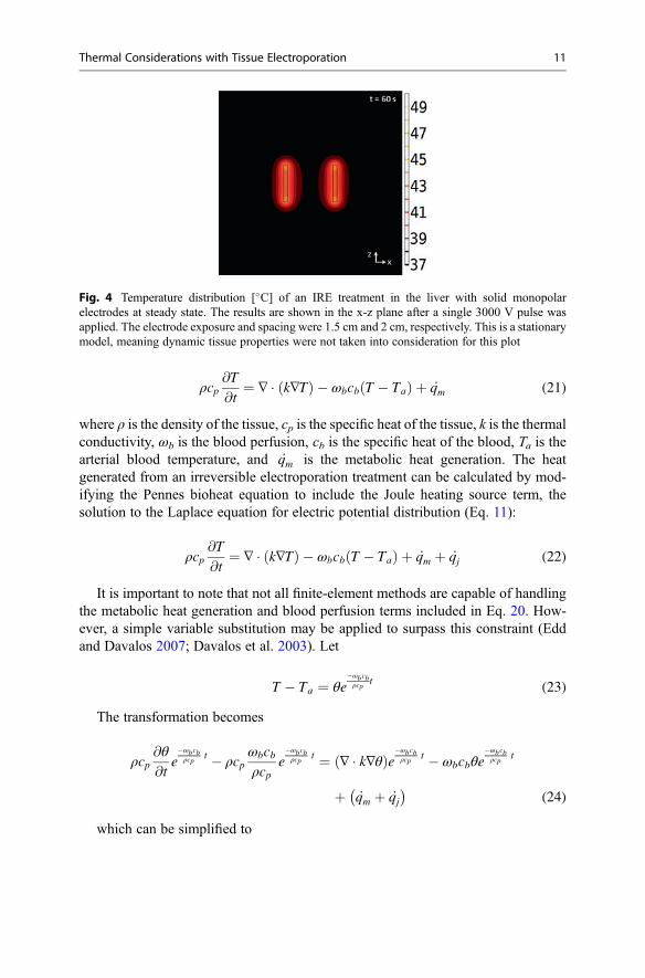
Fig. 4 Temperature distribution [�C] of an IRE treatment in the liver with solid monopolarelectrodes at steady state. The results are shown in the x-z plane after a single 3000 V pulse wasapplied. The electrode exposure and spacing were 1.5 cm and 2 cm, respectively. This is a stationarymodel, meaning dynamic tissue properties were not taken into consideration for this plot
Thermal Considerations with Tissue Electroporation 11
ρcp@θ
@t¼ ∇ � k∇θð Þ þ _qm þ _qj
� �eωbcbρcp
t(25)
This modified bioheat conduction equation with Joule heating is now readilysolvable with most commercially available finite-element packages. The samevariable substitution is applied to the boundary conditions to solve for θ. Subse-quently, this solution is substituted back into the original equation to determine thetemperature distribution in the analyzed domain.
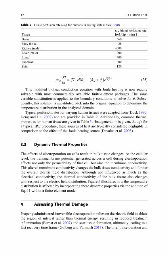
Typical perfusion rates for varying human tissues were adapted from (Duck 1990;Deng and Liu 2002) and are provided in Table 2. Additionally, common thermalproperties for human tissue are given in Table 3. Heat generation is given, though fora typical IRE procedure, these sources of heat are typically considered negligible incomparison to the effect of the Joule heating source (Davalos et al. 2003).
3.3 Dynamic Thermal Properties
The effects of electroporation on cells result in bulk tissue changes. At the cellularlevel, the transmembrane potential generated across a cell during electroporationaffects not only the permeability of that cell but also the membrane conductivity.This altered membrane conductivity changes the bulk tissue conductivity and furtherthe overall electric field distribution. Although not influenced as much as theelectrical conductivity, the thermal conductivity of the bulk tissue also changeswith respect to the electric field distribution. Figure 5 illustrates how the temperaturedistribution is affected by incorporating these dynamic properties via the addition ofEq. 11 within a finite-element model.
4 Assessing Thermal Damage
Properly administered irreversible electroporation relies on the electric field to ablatethe region of interest rather than thermal energy, resulting in reduced treatmentinflammation (Bernat et al. 2007) and scar tissue formation, ultimately leading to afast recovery time frame (Golberg and Yarmush 2013). The brief pulse duration and
Table 2 Tissue perfusion rate (ob) for humans in resting state (Duck 1990)
Tissueωb, blood perfusion rate[mL/(kg � min) ]
Brain 560
Fatty tissue 28
Kidney (male) 4000
Liver (male) 1000
Lung 400
Pancreas 600
Skin 120
12 T.J. O’Brien et al.
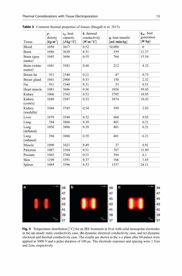
Fig. 5 Temperature distribution [�C] for an IRE treatment in liver with solid monopolar electrodesin the (a) steady static conductivity case, (b) dynamic electrical conductivity case, and (c) dynamicelectrical and thermal conductivity case. The results are shown in the x-z plane after 60 pulses wereapplied at 3000 V and a pulse duration of 100 μs. The electrode exposure and spacing were 1.5cmand 2cm, respectively
Table 3 Common thermal properties of tissues (Hasgall et al. 2015)
Tissue
ρ,density[kg/m3]
cp, heatcapacity[J/kg/�~C]
k, thermalconductivity[W/m/�~C]
q, heat transfer[mL/min/kg]
_qm, heatgeneration[W/kg]
Blood 1050 3617 0.52 10,000 0
Brain 1046 3630 0.51 559 11.37
Brain (graymatter)
1045 3696 0.55 764 15.54
Brain (whitematter)
1041 3583 0.48 212 4.32
Breast fat 911 2348 0.21 47 0.73
Breast gland 1041 2960 0.33 150 2.32
Fat 911 2348 0.21 33 0.51
Heart muscle 1081 3686 0.56 1026 39.45
Kidney 1066 3763 0.53 3795 18.05
Kidney(cortex)
1049 3587 0.53 3874 18.43
Kidney(medulla)
1044 3745 0.54 599 2.85
Liver 1079 3540 0.52 860 9.93
Lung 394 3886 0.39 401 6.21
Lung(deflated)
1050 3886 0.39 401 6.21
Lung(inflated)
394 3886 0.39 401 6.21
Muscle 1090 3421 0.49 37 0.91
Pancreas 1087 3164 0.51 767 11.89
Prostate 1045 3760 0.51 394 6.1
Skin 1109 3391 0.37 106 1.65
Spleen 1089 3596 0.53 1557 24.11
Thermal Considerations with Tissue Electroporation 13
delay between pulses associated with irreversible electroporation help to reduce thechance of thermal heating and the overtreatment of a target tissue region; however,mathematical modeling for thermal damage and preoperative treatment planning canhelp eliminate the chance of thermal damage.
4.1 Damage Equation
Biological tissue is sensitive to temperature. Both the absolute temperature and thethermal exposure duration are central in defining the extent of thermal damage(Diller and Hayes 1983). Methods to calculate the thermal damage due to Jouleheating have been studied for decades (Tropea and Lee 1992; Al-Sakere et al. 2007;Becker and Kuznetsov 2007a; Edd and Davalos 2007; Shafiee et al. 2009; Davaloset al. 2010; Diller and Hayes 1983). Henriques and Morit developed the firstsuccessful analytical model of thermal injury to biological tissue in the late 1940s,which has since been applied to numerous biothermal applications. Using this modelto predict irreversible thermal injury, one must apply the transient temperature fieldto the thermal damage function. This function was derived from governing bio-chemical rate processes depicted in terms of an Arrhenius-type relationship:
@Ω@t
¼ ξe�Ea= R�Tð Þ (26)
where Ω is defined as a non-dimensional damage parameter, ξ is described as thefrequency factor, Ea as the activation energy, R is the universal gas constant, and T isthe absolute temperature in Kelvin. The total injury at any point within the targetedtissue can be obtained by integrating the damage rate function over the treatmentperiod.
Ω ¼ ξ
ðt0
e�Ea=RT tð Þdt (27)
Understanding the thermal effects of the electrical pulse parameters chosen iscritical for a successful, nonthermal treatment therapy. The assessment of whether avoltage amplitude or other pulse parameter will induce thermal damage in addition toirreversible electroporation can be quantified through the use of this thermal damagefunction. Diller et al. have shown that the minimum value for which irreversibleepidermal injury of blood perfused tissue occurs at a value of Ω = 0.53 (Diller andHayes 1983). More recently, Shafiee et al. developed an analytical model to deter-mine the upper bound of irreversible electroporation prior to the onset of thermaldamage as a function of physical cell properties and pulse parameters (Shafiee et al.2009) (Fig. 6).
14 T.J. O’Brien et al.
4.2 Thermal Dose
Another mathematically equivalent method of calculating irreversible thermal dam-age was developed in the 1970s and is widely used to quantify tissue hyperthermiastudies, specifically in tumor hyperthermia studies. The “thermal dose” concept isfundamentally centered around the thermal effect of an equivalent time of exposureat a reference temperature of 43 �C (typical thermal threshold for cell viability)(Pearce 2009). This approach is mathematically illustrated in Eq. 26:
t43 ¼Xt¼final
t¼0
R 43�Ttð ÞΔt (28)
where Tt is the average temperature during the time interval Δt, R is the constant ofproportionality modeled at R = 0.25 for Tt � 43�C and R = 0.5 for when Tt > 43�C,and the t43 is the cumulative equivalent time at 43 �C (Davalos et al. 2010).
5 Numerical Modeling of Electroporation
Clinically, IRE relies on preoperative treatment planning and numerical modeling toensure complete ablation of the target tissue, while simultaneously mitigating theeffects of Joule heating and thermal damage. Currently, monopolar probes are usedfor unresectable tumor ablation. However, a single needle electrode (bipolar probe)geometry is highly desirable as it further reduces the invasiveness associated with atypical monopolar probe IRE procedure.
Figure 7 illustrates the resulting electric field and temperature distribution for theirreversible electroporation of liver tissue after 60 pulses were applied at a voltagepotential (Φsource) of 3000 V and 100 μs using the monopolar probe geometries.Electrical and thermal boundary conditions and initial conditions were set asdescribed in Sect. 2 (surrounding tissue boundaries were electrically insulating,adiabatic).
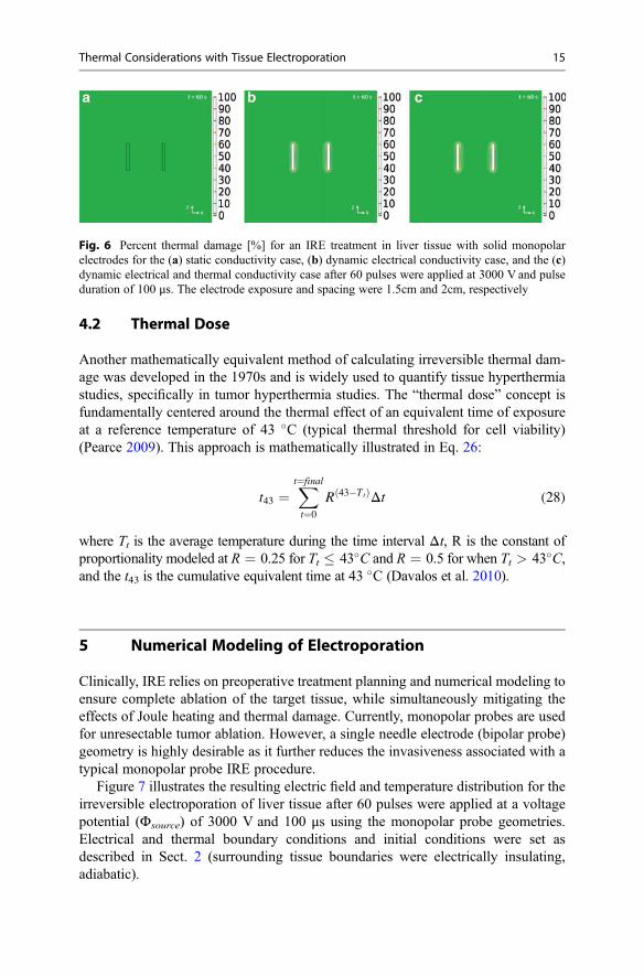
Fig. 6 Percent thermal damage [%] for an IRE treatment in liver tissue with solid monopolarelectrodes for the (a) static conductivity case, (b) dynamic electrical conductivity case, and the (c)dynamic electrical and thermal conductivity case after 60 pulses were applied at 3000 V and pulseduration of 100 μs. The electrode exposure and spacing were 1.5cm and 2cm, respectively
Thermal Considerations with Tissue Electroporation 15
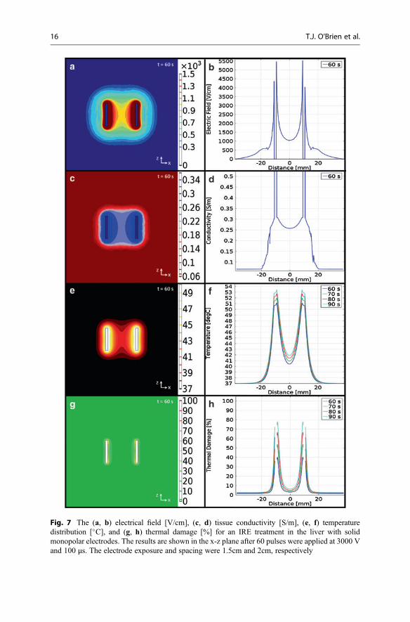
Fig. 7 The (a, b) electrical field [V/cm], (c, d) tissue conductivity [S/m], (e, f) temperaturedistribution [�C], and (g, h) thermal damage [%] for an IRE treatment in the liver with solidmonopolar electrodes. The results are shown in the x-z plane after 60 pulses were applied at 3000 Vand 100 μs. The electrode exposure and spacing were 1.5cm and 2cm, respectively
16 T.J. O’Brien et al.
Similarly, Fig. 8 illustrates the resulting electric field and temperature distributionfor the irreversible electroporation of liver tissue using a bipolar probe. The sameboundary conditions, initial conditions, and pulse parameters were set for this modelwith the addition of an insulating spacer between the source and sink electrodes. Thisspacer geometry was modeled as an electrically insulating material.
5.1 Special Tissue Considerations
In treatment planning, one must consider the heterogeneity of the targeted region as achange or irregularity within the tissue properties can affect the electric field andtemperature distribution. Biological tissues are typically complicated by the pres-ence of blood vessels and an aggregate of dissimilar tissue types. Tissues, likemuscle, can also be anisotropic yielding variable material properties with respectto the direction in which they were measured. Only further complicating the poten-tial field of interest, the presence of conductive materials, such as metallic vascularstents, can create additional anomalies within the electric field and temperaturedistribution.
Since the implementation of Lister’s aseptic technique in surgical procedure inthe 1860s, the implantation of metallic devices has become a regular practice inmedicine (Chen and Thouas 2015). The use of metallic materials has dominated thefield of orthopedic surgery including both temporary (bone plates, pins, screws) andpermanent (total joint replacement) procedures. Further, metal materials have foundapplications in dental, orthodontic practices and various thermal ablation therapies(brachytherapy) and are regularly used in vascular stenting. While the addition ofthese metallic implants have certainly improved the overall wellness and conditionsof hundreds of thousands of patients, these conductive implants do present anobstacle in the application of electroporation.
Irreversible electroporation has developed an increasing interest for the ablationof unresectable tumors, pancreatic and hepatobiliary cancer patients in particular.Many of these patients experience compression on the common bile duct from thetumor resulting in the implantation of a metallic stent to improve biliary drainage andprevent the occurrence of jaundice (Scheffer et al. 2016). The presence of a conduc-tive material will alter both the electric field and thermal distribution. The extent ofthe distortion varies depends on the volume, conductivity, and proximity of theimplant in relation to the targeted region of interest. However, smaller implants suchas metallic seeds from a brachytherapy will have less of an effect than that of a stent.Recently, it was shown that the temperatures directly adjacent to the electrodes,rather than the metallic implant itself, greatly rise in the presence of metallicimplants, such as stents (Scheffer et al. 2016; Neal et al. 2013) (Fig. 9).
Thermal Considerations with Tissue Electroporation 17
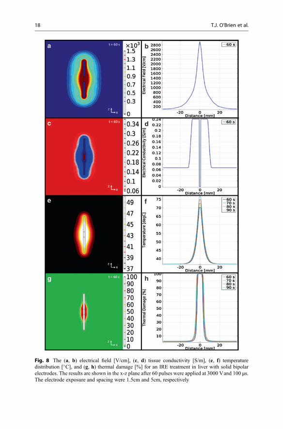
Fig. 8 The (a, b) electrical field [V/cm], (c, d) tissue conductivity [S/m], (e, f) temperaturedistribution [�C], and (g, h) thermal damage [%] for an IRE treatment in liver with solid bipolarelectrodes. The results are shown in the x-z plane after 60 pulses were applied at 3000 Vand 100 μs.The electrode exposure and spacing were 1.5cm and 5cm, respectively
18 T.J. O’Brien et al.
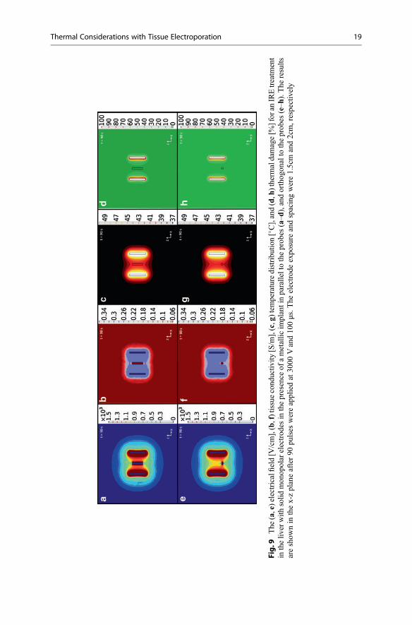
Fig.9
The
(a,e)electricalfi
eld[V
/cm],(b,f)tissuecond
uctiv
ity[S/m
],(c,g)tem
peraturedistribu
tion[�C],and(d,h
)therm
aldamage[%
]for
anIREtreatm
ent
intheliv
erwith
solid
mon
opolar
electrod
esin
thepresence
ofametallic
implantinparalleltotheprob
es(a–d
),andorthog
onalto
theprob
es(e–h
).The
results
areshow
nin
thex-zplaneafter90
pulses
wereappliedat30
00Vand10
0μs.T
heelectrod
eexpo
sure
andspacingwere1.5cm
and2cm,respectively
Thermal Considerations with Tissue Electroporation 19
6 Thermal Mitigation Strategies
From a thermal perspective, the ultimate goal of irreversible electroporation is togenerate necrosis within the targeted region of tissue with minimal to zero influenceof temperature. However, the combination of heterogeneous tissues and conductivematerials implanted within tissues can significantly alter the electric field distributionand thermal distribution. Further, larger irregularly shaped volumes of tissue mayrequire an increase in some of the pulse parameters (i.e., higher voltage potential or ahigher repetition rate), which could lead to an increase in the associated temperature.Accordingly, thermal mitigation strategies are being investigated to further reducethe chance of thermal damage and push the bounds of IRE as a nonthermal ablationtherapy.
6.1 Active Cooling
Two active cooling strategies have been proposed in the literature, including pre-cooling of the tissue (Becker and Kuznetsov 2007b) and internal electrode cooling(Wandel et al. 2016). Cooling of the tissue prior to treatment has been investigatednumerically for skin electroporation procedures using plate electrodes. In the finite-element model presented by Becker et al., the tissue was cooled for 1 minute prior totreatment by applying an ambient temperature of 10 �C. Compared to a control roomtemperature of 20 �C, precooling the tissue by 10 �C decreased the peak temperatureposttreatment by nearly 5 �C. With respect to thermal damage, the cumulativeeffective minutes at 43 �C (thermal dose alternative to the Arrhenius damagemodel (Pearce 2009)) was reduced from 1000 min to 40 min. Therefore, precoolingsignificantly reduced the risk of thermal damage (Becker and Kuznetsov 2007b).This technique may have limited applicability to superficial procedures wherein thecooling can be readily applied.
Internal electrode cooling has been investigated experimentally in healthy tissueusing a single-insertion, bipolar probe. The bipolar probe contains both the sourceand sink electrodes within a single needle separated by a gap of 8 mm. In a controlstudy without internal cooling, a 3.0 cm ablation width was achieved when 6 sets of50 pulses were applied at 3000 Vand 100 μs. The temperature of the internal coolingsolution had a profound effect of the ablation size. When the solution was warmed tobody temperature (37 �C), the ablation length was 3.1 � 0.1 cm, and when thesolution was cooled (4–10 �C), the ablation diameter was 2.3 � 0.1 cm. Addition-ally, both the warmed and cooled perfusate reduced current spikes and subsequentgenerator crashes. It was thought that the difference in ablation size between thewarmed and cooled perfusate was due to an optimal balance between mitigatingexcessive tissue electric conductivity changes to reduce the likelihood of arching andmaintaining the spread of the electric field distribution (Wandel et al. 2016).
To illustrate the effects of internal electrode cooling, the boundary conditions ofthe monopolar electrode treatment in the liver were modified, as described in Sect. 4.Specifically, the edges of the electrodes were set to a constant temperature of either
20 T.J. O’Brien et al.
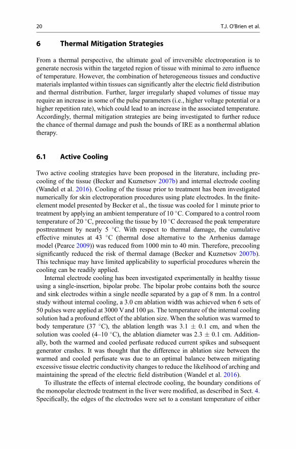
10 �C or 37 �C. The goal of active cooling is to hold the electrode to the sametemperature as the perfusate during treatment. By assigning a constant temperatureboundary condition, it is assumed that this goal has been achieved. In the case of the10 �C perfusate, it is evident that the electrical conductivity surrounding the probes isreduced (Fig. 10j) compared to the control case (Fig. 10b). This is a result of thecooler temperatures near the probe (Fig. 10k) and the simulated temperature depen-dence of conductivity. No cell death due to thermal damage is present (Fig. 10l),which was defined as
TKP ¼ 100 1� e�Ω tð Þ� �
, (29)
where TKP represents the thermal kill percentage and Ω is the thermal damage as afunction of time. The major trade-off to using a 10 �C perfusate is the reduced spreadof the electric field distribution. Assuming an electric field threshold of 423 V/cm forIRE in the liver (Sano et al. 2010), the predicted width of the ablation in the verticalx-direction is 3.97 cm for the 10 �C perfusate and 4.35 cm for the control case. Thiscan be observed qualitatively by comparing the electric field contours in Fig. 10. Byusing a 37 �C perfusate, the percent of cell death due to thermal damage is notcompletely eliminated; however, it is limited to 10% (Fig. 10h). Additionally, thespread of the electric field (Fig. 10e) closely resembles the control case (Fig. 10a),and the ablation width is 4.28 cm. These are the same trends that were observedexperimentally using a bipolar probe (Wandel et al. 2016). This phenomenon can beexplained with the concept of a “virtual” electrode. It is known that electrodes with agreater diameter increase the spread of the electric field (Edd and Davalos 2007). Ifthe conductivity adjacent to the electrode increases, either by electroporation ortemperature, the “virtual” diameter of the electrode increases along with the ablationsize. The opposite is also true of lower conductivities.
Other authors have explored the effects of temperature on the electric fielddistribution. Daniels and Rubinsky proposed a method for indirectly manipulatingthe electric field by taking advantage of the temperature dependence of electricalconductivity (Daniels and Rubinsky 2011). When using a single probe with activecooling, the electric field is magnified (~2x) in the cold regions surrounding theelectrode. The lower temperatures yield a lower electrical conductivity, and there is agreater voltage drop that occurs across this region. Alternatively, the electric fieldbeyond the cooled area is slightly suppressed (~1.1x), which would lead to smallerablations. This scenario can be approximated by a voltage divider circuit, with atemperature-induced resistance in series with the original tissue. The authors alsodescribe the parallel resistance case, in which a separate cooling probe is placed inthe treatment zone. This probe serves to reduce the surrounding electric field. It cantheoretically be placed adjacent to critical structures to protect them from IRE andthermal damage (Fig. 11).
Another layer of complication arises when incorporating the effects of tempera-ture on the electric field threshold for electroporation. Tissues are more susceptible toelectroporation at high temperatures (i.e., the field threshold increases as temperature
Thermal Considerations with Tissue Electroporation 21
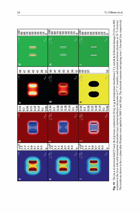
Fig.1
0The
(a,e,i)electricalfi
eld[V
/cm],(b,f,j)tissuecond
uctiv
ity[S/m
],(c,g,k
)tem
peraturedistribu
tion[�C],and(d,h
,l)therm
aldamage[%
]for
anIRE
treatm
entintheliv
erwith
solid
mon
opolar
electrod
es(top
),internalperfusionelectrod
esat37
� C(m
iddle),and
internalperfusionelectrod
esat10
� C(bottom).
The
results
areshow
ninthex-zplaneafter90
pulses
wereappliedat30
00Vand10
0μs.T
heelectrod
eexpo
sureandspacingwere1.5cmand2cm,respectively
22 T.J. O’Brien et al.
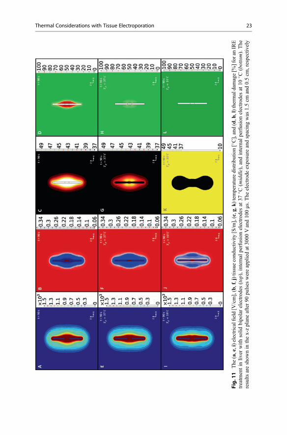
Fig.1
1The
(a,e,i)electricalfi
eld[V
/cm],(b,f,j)tissuecond
uctiv
ity[S/m
],(c,g,k
)tem
peraturedistribu
tion[�C],and(d,h
,l)therm
aldamage[%
]for
anIRE
treatm
entin
liver
with
solid
bipo
larelectrod
es(top
),internal
perfusionelectrod
esat37
� C(m
iddle),and
internal
perfusionelectrod
esat10
� C(bottom).The
results
areshow
nin
thex-zplaneafter90
pulses
wereappliedat30
00Vand10
0μs.T
heelectrod
eexpo
sure
andspacingwas
1.5cm
and0.5cm
,respectively
Thermal Considerations with Tissue Electroporation 23
decreases) (Gallo et al. 2002). This effect is thought to be minimal compared totemperature and electroporation-dependent conductivity changes (Daniels andRubinsky 2011). However, it may explain why the difference in ablation widthbetween the 10 �C perfusate and control was greater experimentally (Wandel et al.2016) than predicted by the mode (Fig. 4). Additionally, Joule heating at theelectroporated sites may give rise to a self-catalyzing process that results in a lipidmelting phase transition and creation of localized transport regions (Pliquett 1999;Pliquett et al. 2008; Becker and Kuznetsov 2007b). Taken together, these studiesindicate that further experimentation is required to ensure continued validation ofexisting treatment planning algorithms, which rely on accurate predictions of theelectric field distribution and knowledge of a predetermined electric field thresholdfor IRE.
6.2 Phase Change Material (PCM)
While active cooling designs are effective at mitigating thermal damage, the asso-ciated equipment can be complicated and costly to implement, especially in treat-ments requiring more than one pair of electrodes. To alleviate these concerns,researchers have developed initial designs for a passive heat storage system thatincorporates phase change materials (PCMs) into the electrode core (Arena et al.2012; Arena et al. 2013). When a material undergoes an endothermic phase change,energy that is absorbed from the environment contributes to the disruption ofmolecular interactions, stalling temperature rise. The energy is released when thephase change process is reversed. Therefore, PCMs are used in situations that benefitfrom maintaining a constant temperature. This primarily includes industrial applica-tions, such as home insulation (Kuznik et al. 2011) and electronic devices(Kandasamy et al. 2007).
With respect to IRE, theoretical models indicate that there is a trade-off betweenelectrode diameter and temperature mitigation (Arena et al. 2012). Larger electrodes(2 mm Ø) can hold a greater volume of PCM and are capable of lowering theprobability for thermal damage over the entire time course of the treatment. Whenusing smaller electrodes (<2 mm Ø), the phase transition is completed midwaythrough treatment, and the probability for thermal damage closely resembles con-ventional, metal electrodes. Experimental testing has been performed at roomtemperature using gallium (melting point = 29.8 �C) (Arena et al. 2013). Comparedto other classes of PCMs (salt hydrates and organics), the metallic gallium exhibits ahigher thermal conductivity, which aids in melting and heat dissipation. However, toachieve optimal clinical results, care must be taken to tune the melting point of thePCM based on the desired pulse protocol.
To illustrate the effects of a PCM core, a metallic PCM was incorporated into themonopolar electrode model that was described in Sect. 2. All materials propertieswere chosen to be consistent with gallium (Arena et al. 2013), except for themelting point, which was arbitrarily set to two degrees above ambient temperature(39 �C). Practically, this could be achieved through alloying gallium with bismuth
24 T.J. O’Brien et al.
(Predel 1960). The effective heat capacity method was implemented to account forthe solid-to-liquid phase transition. The technique incorporates the latent heat offusion, λ (80.2 kJ/kg), into the volume average of the specific heat capacity atconstant pressure:
cp, eq ¼ Θ cp, s þ λΠ� �þ 1� Θð Þ cp, l þ λΠ
� �(30)
where Θ is the volume fraction of solid material defined by 1 – flc2hs((T-TM),TR) andTM is the melting temperature over the transition range, TR. This function approxi-mates the logical step Θ = 1 for T < TM and Θ = 0 for T > TM by smoothing thetransition within the interval TM – TR < T < TM + TR using a continuous secondderivative. The term Π is a normalized pulse around the transition temperaturedefined by differentiating Θ with respect to temperature. Inside the PCM domains,the volume averages of the density, ρeq, and thermal conductivity, keq, were defined as
peq ¼ Θρs þ 1� Θð Þρl (31)
keq ¼ Θks þ 1� Θð Þkl (32)
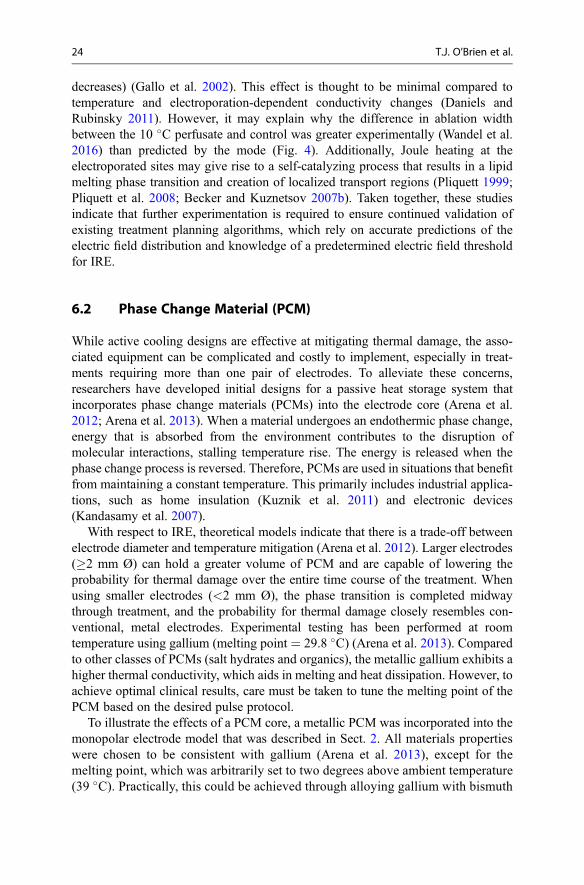
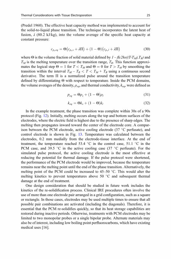
In the example treatment, the phase transition was complete within 30s of a 90sprotocol (Fig. 12). Initially, melting occurs along the top and bottom surfaces of theelectrodes, where the electric field is highest due to the presence of sharp edges. Themelting then propagates inward toward the center of the electrode core. A compar-ison between the PCM electrode, active cooling electrode (37 �C perfusate), andcontrol electrode is shown in Fig. 13. Temperature was calculated between theelectrodes, 0.2 mm medially from the electrode-tissue interface. At the end oftreatment, the temperature reached 53.4 �C in the control case, 51.1 �C in thePCM case, and 39.5 �C in the active cooling case (37 �C perfusate). For thesimulated pulse protocol, the active cooling electrode is the most effective atreducing the potential for thermal damage. If the pulse protocol were shortened,the performance of the PCM electrode would be improved, because the temperatureremains near the melting point until the end of the phase transition. Alternatively, themelting point of the PCM could be increased to 45–50 �C. This would alter themelting kinetics to prevent temperatures above 50 �C and subsequent thermaldamage at the end of treatment.
One design consideration that should be studied in future work includes thekinetics of the re-solidification process. Clinical IRE procedures often involve theuse of more than one electrode pair arranged in a grid configuration, such as a squareor rectangle. In those cases, electrodes may be used multiple times to ensure that allpossible pair combinations are activated (including the diagonals). Therefore, it isessential that the PCM re-solidifies quickly, so that its heat storage capabilities arerestored during inactive periods. Otherwise, treatments with PCM electrodes may belimited to two monopolar probes or a single bipolar probe. Alternate materials mayalso be of interest, including low boiling point perfluorocarbons, which have existingmedical uses [16].
Thermal Considerations with Tissue Electroporation 25
7 Concluding Remarks
Irreversible electroporation outcomes are contingent on the generated electric field toincrease the transmembrane potential and ultimately induce a permeabilization of thecellular membranes within the targeted tissue region. Proper adjustment of the pulseparameters for tissue electroporation is performed to limit Joule heating of theelectrodes and, more importantly, tissue heating such that it is below a thermallydamaging threshold. Though, challenges can arise in the balance of effective treat-ment protocol and thermal mitigation strategy for larger or irregularly shapedvolumes of tissues. Ablation size is constrained by the electrode geometry, electrodespacing, voltage amplitude, pulse frequency, and pulse repetition. Thus, researchers
Fig. 12 Volume fraction solid material of PCM core during IRE treatment of the liver with phasechange electrodes. Only one electrode from the monopolar pair is shown at each time step. Theresults are shown in the z-x plane during pulsing at 3000 Vand 100 μs. The electrode exposure andspacing were 1.5cm and 2cm, respectively
Fig. 13 Temperature profilesfor three different electrodetypes in a monopolarconfiguration (control, solidline; phase change, dashedline; and active cooling,dotted line)
26 T.J. O’Brien et al.
are striving for methods to maintain tissue temperature below the thermally damag-ing threshold while increasing the overall ablation dimensions. To do this, someresearchers have looked toward the use of actively cooled electrodes and phasechange material to reduce the probe and surrounding tissue temperature as well asallow for an increase in voltage amplitude and repetition of pulses. Similarly, theconcept of increasing the frequency of pulses, such that a “burst” of pulsed electricfields are delivered, has been shown to reduce the overall treatment time and allowfor the use of higher voltages. One example of this high-frequency electroporationtreatment is known as nanosecond pulsed electric fields (nsPEFs). This metholodgyis also an independent, nonthermal tissue ablation technique that utilizes an electricfield strength an order of magnitude greater (~100 kV cm�1) for durations an orderof magnitude shorter (~100 ns) than those typically used for ECT, EGT, and IRE.Further, research has shown that nsPEFs can cause electroporation of the intracel-lular organelle membranes (Garon et al. 2007; Stacey et al. 2003; Vernier et al. 2006;Long et al. 2011; Frey et al. 2006; N. Chen et al. 2004; Nuccitelli et al. 2010).
Acknowledgments This work was supported by the NSF CAREER Award (CBET-1055913), theR21 Award from the National Cancer Institute of the National Institutes of Health (R21CA192042),and the Institute of Critical Technology and Applied Science at Virginia Tech.
8 Cross-References
▶Heat Transfer In Vivo▶Numerical Methods▶ Phase Change Materials▶ Single Phase and Multiphase Flow in Electronic Cooling
References
Abidor IG, Arakelyan VB, Chernomordik LV, Chizmadzhev YA, Pastushenko VF, Tarasevich MP(1979) Electric breakdown of bilayer lipid membranes. I. The main experimental facts and theirqualitative discussion. J Electroanal Chem 104(C):37–52. doi:10.1016/S0022-0728(79)81006-2
Al-Sakere B, André F, Bernat C, Connault E, Opolon P, Davalos RV, Rubinsky B, Mir LM (2007)Tumor ablation with irreversible electroporation. PLoS One 2(11):1–8. doi:10.1371/journal.pone.0001135
Arena CB, Mahajan RL, Rylander MN, Davalos RV (2013) An experimental and numericalinvestigation of phase change electrodes for therapeutic irreversible electroporation. J BiomechEng 135(11):111009. doi:10.1115/1.4025334
Arena CB, Mahajan RL, Rylander MN, Davalos RV (2012) Towards the development of latent heatstorage electrodes for electroporation-based therapies. Appl Phys Lett 101(8):1–5. doi:10.1063/1.4747332
Bao N, Le TT, Cheng J-X, Chang L (2010) Microfluidic electroporation of tumor and blood cells:observation of nucleus expansion and implications on selective analysis and purging of circu-lating tumor cells. Integr Biol (Camb) 2(2–3):113–120. doi:10.1039/b919820b
Thermal Considerations with Tissue Electroporation 27
Becker SM, Kuznetsov AV (2007a) Numerical assessment of thermal response associated within vivo skin electroporation: the importance of the composite skin model. J Biomech Eng129:330–340. doi:10.1115/1.2720910
Becker SM, Kuznetsov AV (2007b) Thermal damage reduction associated with in vivo skinelectroporation: a numerical investigation justifying aggressive pre-cooling. Int J Heat MassTransf 50(1–2):105–116. doi:10.1016/j.ijheatmasstransfer.2006.06.030
Belehradek M, Domenge C, Luboinski B, Orlowski S, Belehradek J, Mir LM (1993) Electro-chemotherapy, a new antitumor treatment: first clinical phase I-II trial. Cancer 72(12): 3694–3700.doi:10.1002/1097-0142(19931215)72:12<3694::AID-CNCR2820721222>3.0.CO;2-2
Bernat C, André F, Connault E, Opolon P, Davalos RV, Mir LM (2007) A study of the immuno-logical response to tumor ablation with irreversible electroporation. Technol Cancer Res Treat6(4):301–306
Cadossi R, Ronchetti M, Cadossi M (2014) Locally enhanced chemotherapy by electroporation:clinical experiences and perspective of use of electrochemotherapy. Future Oncol 10(5):877–890. doi:10.2217/fon.13.235
Cemazar M, Tamzali Y, Sersa G, Tozon N, Mir LM, Miklavcic D, Lowe R, Teissie J (2008)Electrochemotherapy in veterinary oncology. J Vet Intern Med 22(4):826–831. doi:10.1111/j.1939-1676.2008.0117.x
Chen N, Schoenbach KH, Kolb JF, James Swanson R, Garner AL, Yang J, Joshi RP, Beebe SJ(2004) Leukemic cell intracellular responses to nanosecond electric fields. Biochem BiophysRes Commun 317(2):421–427. doi:10.1016/j.bbrc.2004.03.063
Chen Q, Thouas GA (2015) Metallic implant biomaterials. Mater Sci Eng R 87:1–57. doi:10.1016/j.mser.2014.10.001. Elsevier B.V
Daniels CS, Rubinsky B (2011) Temperature modulation of electric fields in biological matter.PLoS One 6(6):1–9. doi:10.1371/journal.pone.0020877
Davalos RV, Mir LM, Rubinsky B (2005) Tissue ablation with irreversible electroporation. AnnBiomed Eng 33(2):223–231. doi:10.1007/s10439-005-8981-8
Davalos RV, Rubinsky B (2008) Temperature considerations during irreversible electroporation.Int J Heat Mass Transf 51(23–24):5617–5622. doi:10.1016/j.ijheatmasstransfer.2008.04.046.Elsevier Ltd
Davalos RV, Rubinsky B, Mir LM (2003) Theoretical analysis of the thermal effects during in vivotissue electroporation. Bioelectrochemistry 61(1–2):99–107. doi:10.1016/j.bioelechem.2003.07.001
Davalos RV, Garcia PA, Edd JF (2010) Thermal aspects of irreversible electroporation. pp 123–154Deng Z-S, Liu J (2002) Analytical study on bioheat transfer problems with spatial or transient
heating on skin surface or inside biological bodies. J Biomech Eng 124(6):638. doi:10.1115/1.1516810
Diller KR, Hayes LJ (1983) A finite element model of burn injury in blood-perfused skin.J Biomech Eng 105(3):300–307. doi:10.1115/1.3138423
Domenge C, Luboinski B, De Baere T, Schwaab G, Belehradek J Jr, Mir LM, Orlowski S (1996)Antitumor electrochemotherapy: new advances in the clinical protocol. Cancer 77(5):956–963
Duck FA (1990) Physical properties of tissues: a comprehensive reference book. Academic Press,San Diego
Edd JF, Davalos RV (2007) Mathematical modeling of irreversible electroporation for treatmentplanning. Technol Cancer Res Treat 6(4):275–286. doi:10.1177/153303460700600403
Ellis TL, Garcia PA, Rossmeisl JH, Henao-Guerrero N, Robertson J, Davalos RV (2011) Nonther-mal irreversible electroporation for intracranial surgical applications. Laboratory investigation.J Neurosurg 114(3):681–688. doi:10.3171/2010.5.JNS091448
Fok SC, Shen W, Tan FL (2010) Cooling of portable hand-held electronic devices using phasechange materials in finned heat sinks. Int J Therm Sci 49(1):109–117. doi:10.1016/j.ijthermalsci.2009.06.011. Elsevier Masson SAS
28 T.J. O’Brien et al.
Frey W, White JA, Price RO, Blackmore PF, Joshi RP, Nuccitelli R, Beebe SJ, Schoenbach KH,Kolb JF (2006) Plasma membrane voltage changes during nanosecond pulsed electric fieldexposure. Biophys J 90(10):3608–3615. doi:10.1529/biophysj.105.072777. Elsevier
Gallo S, Sen A, Hensen M, Hui SW (2002) Temperature-Dependent Electrical and UltrastructuralCharacterizations of Porcine Skin upon Electroporation. Biophys J 82(1 Pt 1):109–119.doi:10.1016/S0006-3495(02)75378-2. Elsevier
Garcia PA, Rossmeisl JH Jr, Neal RE 2nd, Ellis TL, Davalos RV (2011) A parametric studydelineating irreversible electroporation from thermal damage based on a minimally invasiveintracranial procedure. Biomed Eng Online 10(April):34. doi:10.1186/1475-925X-10-34
Garcia P, Rossmeisl J, Robertson J, Ellis T, Davalos R (2009) Irreversible electroporation forintracranial surgery: a pilot study in a canine model. Neuro-Oncology 11(5):588
Garcia P, Rossmeisl J, Neal R, Ellis T, Olson J, Henao-Guerrero N, Robertson J, Davalos R (2010)Intracranial nonthermal irreversible electroporation: in vivo analysis. J Membr Biol 236(1):127–136. doi:10.1007/s00232-010-9284-z
Garon EB, David S, Thomas Vernier P, Tang T, Sun Y, Marcu L, Gundersen MA, Phillip Koeffler H(2007) In vitro and in vivo evaluation and a case report of intense nanosecond pulsed electricfield as a local therapy for human malignancies. Int J Cancer 121(3):675–682. doi:10.1002/ijc.22723
Gascoyne PR, Vykoukal J (2002) Particle separation by dielectrophoresis. Electrophoresis 23(13):1973–1983. doi:10.1002/1522-2683(200207)23
Ge H, Liu J (2012) Phase change effect of low melting point metal for an automatic cooling of USBflash memory. Front Energy 6(3):207–209. doi:10.1007/s11708-012-0204-z
Gehl J (2003) Electroporation: theory and methods, perspectives for drug delivery, gene therapy andresearch. Acta Physiol Scand 177(4):437–447. doi:10.1046/j.1365-201X.2003.01093.x
Glaser RW, Leikin SL, Chernomordik LV, Pastushenko VF, Sokirko AI (1988) Reversible electricalbreakdown of lipid bilayers: formation and evolution of pores. Biochim Biophys Acta940:275–287
Golberg A, Yarmush ML (2013) Nonthermal irreversible electroporation: fundamentals, applications,and challenges. IEEE Trans Biomed Eng 60(3):707–714. doi:10.1109/TBME.2013.2238672
Golzio M, Mazzolini L, Ledoux A, Paganin A, Izard M, Hellaudais L, Bieth A et al (2007) In vivogene silencing in solid tumors by targeted electrically mediated siRNA delivery. Gene Ther14(9):752–759. doi:10.1038/sj.gt.3302920
Granot Y, Rubinsky B (2009) Mass transfer model for drug delivery in tissue cells with reversibleelectroporation. Int J Heat Mass Transf 5(6):611–618. doi:10.1039/b417245k.Effects
Guo Y, Zhang Y, Klein R, Nijm GM, Sahakian AV, Omary RA, Yang GY, Larson AC (2010)Irreversible electroporation therapy in the liver: longitudinal efficacy studies in a rat model ofhepatocellular carcinoma. Cancer Res 70(4):1555–1563. doi:10.1158/0008-5472.CAN-09-3067
Hanna E, Zhang X, Woodlis J, Breau R, Suen J, Li S (2001) Intramusclar electroporation delivery ofIL-12 gene for treatment of squamous cell carcinoma located at distant site. Cancer Gene Ther8(3):151–157
Hasgall PA, Di Gennaro F, Baumgartner C, Neufeld E, Gosselin MC, Payne D, Klingenbock A,Kuster N (2015) IT’IS database for thermal and electromagnetic parameters of biologicaltissues, Version 3.0. doi:10.13099/VIP21000-03-0
Jiang C, Davalos RV, Bischof JC (2015) A review of basic to clinical studies of irreversibleelectroporation therapy. IEEE Trans Biomed Eng 62(1):4–20
Kandasamy R, Wang X-Q, Mujumdar AS (2007) Application of phase change materials in thermalmanagement of electronics. Appl Therm Eng 27(17–18):2822–2832. doi:10.1016/j.applthermaleng.2006.12.013
Karlessi T, Santamouris M, Synnefa A, Assimakopoulos D, Didaskalopoulos P, Apostolakis K(2011) Development and testing of PCM doped cool colored coatings to mitigate urban HeatIsland and Cool Buildings. Build Environ 46(3):570–576. doi:10.1016/j.buildenv.2010.09.003.Elsevier Ltd
Thermal Considerations with Tissue Electroporation 29
Kos B, Zupanic A, Kotnik T, Snoj M, Sersa G, Miklavcic D (2010) Robustness of treatmentplanning for electrochemotherapy of deep-seated tumors. J Membr Biol 236(1):147–153.doi:10.1007/s00232-010-9274-1
Kuznik F, David D, Johannes K, Roux JJ (2011) A review on phase change materials integrated inbuilding walls. Renew Sust Energ Rev 15(1):379–391. doi:10.1016/j.rser.2010.08.019
Li S, Xia X, Zhang X, Suen J (2002) Regression of tumors by IFN-alpha electroporation genetherapy and analysis of the responsible genes by cDNA array. Gene Ther 9(6):390–397.doi:10.1038/sj.gt.3301645
Long G, Shires PK, Plescia D, Beebe SJ, Kolb JF, Schoenbach KH (2011) Targeted tissue ablationwith nanosecond pulses. IEEE Trans Biomed Eng 58(8):2161–2167. doi:10.1109/TBME.2011.2113183
Mesalhy O, Lafdi K, Elgafy A (2006) Carbon foam matrices saturated with PCM for thermalprotection purposes. Carbon 44(10):2080–2088. doi:10.1016/j.carbon.2005.12.019
Miklavcic D, Basu S, Hassenplug JC, Kramer DB, Xu S, Kesselheim AS (2014) Electro-chemotherapy: from the drawing board into medical practice. Biomed Eng Online 13(1):29.doi:10.1186/1475-925X-13-29
Miklavcic D, Sel D, Cukjati D, Batiuskaite D, Slivnik T, Mir L (2004) Sequential finite elementmodel of tissue electropermeabilisation. Conference proceedings: annual international confer-ence of the IEEE engineering in medicine and biology society. IEEE Engineering in Medicineand Biology Society Conference, vol 5(5):3551–3554. doi:10.1109/IEMBS.2004.1403998
Miklavcic D, Snoj M, Zupanic A, Kos B, Cemazar M, Kropivnik M, Bracko M, Pecnik T,Gadzijev E, Sersa G (2010) Towards treatment planning and treatment of deep-seated solidtumors by electrochemotherapy. Biomed Eng Online 9:10. doi:10.1186/1475-925X-9-10
Mondieig D, Rajabalee F, Laprie A, Oonk HAJ, Calvet T, Cuevas-Diarte MA (2003) Protection oftemperature sensitive biomedical products using molecular alloys as phase change material.Transfus Apher Sci 28(2):143–148. doi:10.1016/S1473-0502(03)00016-8
Neal RE, Smith RL, Kavnoudias H, Rosenfeldt F, Ruchong O, McLean CA, Davalos RV,Thomson KR (2013) The effects of metallic implants on electroporation therapies: feasibilityof irreversible electroporation for brachytherapy salvage. Cardiovasc Intervent Radiol 36(6):1638–1645. doi:10.1007/s00270-013-0704-1
Neumann E, Schaefer-Ridder M, Wang Y, Hofschneider PH (1982) Gene transfer into mouse lyomacells by electroporation in high electric fields. EMBO J 1(7):841–845. doi:10.1385/1-59259-409-3:55
Nuccitelli R, Tran K, Sheikh S, Athos B, Kreis M, Nuccitelli P (2010) Optimized nanosecondpulsed electric field therapy can cause murine malignant melanomas to self-destruct with asingle treatment. Int J Cancer 127(7):1727–1736. doi:10.1002/ijc.25364
Osterman E, Tyagi VV, Butala V, Rahim NA, Stritih U (2012) Review of PCM based coolingtechnologies for buildings. Energ Buildings 49:37–49. doi:10.1016/j.enbuild.2012.03.022.Elsevier B.V.
Pavliha D, Kos B, Županič A, Marčan M, Serša G, Miklavčič D (2012) Patient-specific treatmentplanning of electrochemotherapy: procedure design and possible pitfalls. Bioelectrochemistry87:265–273. doi:10.1016/j.bioelechem.2012.01.007
Pearce JA (2009) Relationship between Arrhenius models of thermal damage and the CEM43 thermal dose. Proc SPIE 7181(2):1–15. doi:10.1117/12.807999
Pennes H (1948) Analysis of tissue and arterial blood temperatures in the resting human forearm.J Appl Physiol 85:5–34. doi:9714612
Pliquett U (1999) Mechanistic studies of molecular transdermal transport due to skin electropora-tion. Adv Drug Deliv Rev 35(1):41–60. doi:10.1016/S0169-409X(98)00062-3
Pliquett U, Gusbeth C, Nuccitelli R (2008) A Propagating Heat Wave Model of Skin Electropora-tion. J Theor Biol 251(2):195–201. doi:10.1016/j.jtbi.2007.11.031
Prakash J, Garg HP, Datta G (1985) A solar water heater with a built-in latent heat storage. EnergyConvers Manag 25(1):51–56. doi:10.1016/0196-8904(85)90069-X
30 T.J. O’Brien et al.
Roman KK, O’Brien T, Alvey JB, Woo OJ (2016) Simulating the effects of cool roof and PCM(Phase Change Materials) based roof to mitigate UHI (Urban Heat Island) in prominent UScities. Energy 96:103–117. doi:10.1016/j.energy.2015.11.082. Elsevier Ltd
Rubinsky J, Onik G, Mikus P, Rubinsky B (2008) Optimal parameters for the destruction of prostatecancer using irreversible electroporation. J Urol 180(6):2668–2674. doi:10.1016/j.juro.2008.08.003. American Urological Association
Sano MB, Neal RE, Garcia PA, Gerber D, Robertson J, Davalos RV (2010) Towards the creation ofdecellularized organ constructs using irreversible electroporation and active mechanical perfu-sion. Biomed Eng Online 9(1):1–16. doi:10.1186/1475-925X-9-83. BioMed Central Ltd: 83
Scheffer HJ, Vogel JA, Van Den Bos W, Neal RE, Van Lienden KP, Besselink MGH, VanGemert MJC et al (2016) The influence of a metal stent on the distribution of thermal energyduring irreversible electroporation. PLoS One 11(2):1–13. doi:10.1371/journal.pone.0148457
Shafiee H, Garcia P, Davalos RV (2009) A preliminary study to delineate irreversible electropora-tion from thermal damage using the Arrhenius equation. J Biomech Eng 131(7):074509.doi:10.1115/1.3143027
Sharma A, Tyagi VV, Chen CR, Buddhi D (2009) Review on thermal energy storage with phasechange materials and applications. Renew Sust Energ Rev 13(2):318–345. doi:10.1016/j.rser.2007.10.005
Sheeran PS, Luois SH, Mullin LB, Matsunaga TO, Dayton PA (2012) Design of ultrasonically-activatable nanoparticles using low boiling point perfluorocarbons. Biomaterials 33(11):3262–3269. doi:10.1016/j.biomaterials.2012.01.021. Elsevier Ltd
Shim H, McCullough EA, Jones BW (2001) Using phase change materials in clothing. Text Res J71(6):495–502. doi:10.1177/004051750107100605
Stacey M, Stickley J, Fox P, Statler V, Schoenbach K, Beebe SJ, Buescher S (2003) Differentialeffects in cells exposed to ultra-short, high intensity electric fields: cell survival, DNA damage,and cell cycle analysis. Mutat Res 542(1–2):65–75. doi:10.1016/j.mrgentox.2003.08.006
Tracy CR, Kabbani W, Cadeddu JA (2011) Irreversible Electroporation (IRE): a novel method forrenal tissue ablation. BJU Int 107(12):1982–1987. doi:10.1111/j.1464-410X.2010.09797.x
Tropea BI, Lee RC (1992) Thermal injury kinetics in electrical trauma. J Biomech Eng 114(2):241–250. doi:10.1115/1.2891378
Vernier PT, Sun Y, Gundersen MA (2006) Nanoelectropulse-driven membrane perturbation andsmall molecule permeabilization. BMC Cell Biol 7(1):37. doi:10.1186/1471-2121-7-37
Wandel A, Ben-David E, Said Ulusoy B, Neal R, Faruja M, Nissenbaum I, Gourovich S, NahumGoldberg S (2016) Optimizing irreversible electroporation ablation with a bipolar electrode.J Vasc Interv Radiol 7:1–12. doi:10.1016/j.jvir.2016.06.001. Elsevier
Weaver JC (1994) Molecular Basis for Cell Membrane Electroporation. Ann N YAcad Sci 720(1):141–152. doi:10.1111/j.1749-6632.1994.tb30442.x
Weaver JC (1995) Electroporation in cells and tissues: a biophysical phenomenon due to electro-magnetic fields ions medium. 30(1):205–221.
Thermal Considerations with Tissue Electroporation 31