Embed Size (px)
Citation preview
Pergamon J. Mech. Phys. Solids, Vol. 43, No. 8, pp. 1175-I 198, 1995
Copyright 0 1995 Elsevier Science Ltd Printed in Great Britain. All rights reserved
00224096(95)00033-X 0022-5096/95 $9.50+0.00
THERMAL CONDUCTIVITY AND EXPANSION OF CROSS- PLY COMPOSITES WITH MATRIX CRACKS
T. J. LU and J. W. HUTCHINSON
Division of Applied Sciences, Harvard University, Cambridge, MA 02138, U.S.A
(Receiaed 2 December 1994; in revised form 10 March 1995)
ABSTRACT
Theoretical models are developed for heat conduction and thermal expansion in a fiber-reinforced ceramic cross-ply laminate containing an array of parallel transverse matrix cracks. Two stages of the transverse matrix cracks are considered : Stage-I with tunnel cracks in the 90” plies aligned parallel to the fibers, and Stage-II with cracks extended across both the 90 and 0” plies with intact fibers bridging the matrix in the 0” plies. The effect of debonded fiber-matrix interfaces in the 0” plies is also considered in Stage-II. Approximate closed form solutions for the overall in-plane thermal conductivities and coefficients of thermal expansion (CTEs) as functions of matrix crack spacing and constituent properties are obtained using an approach which combines an analysis akin to a shear-lag analysis with finite element results. Emphasis is placed on the important class of composites whose fiber expansivity is smaller than that of the matrix. For this class, matrix cracking and interfacial debonding results in reduced thermal expansivity. Interfacial debonding has a significant effect on both longitudinal conductivity and thermal expansivity, especially the latter. Comparisons between the present model predictions and numerical and experimental results are provided where these are available.
1. INTRODUCTION
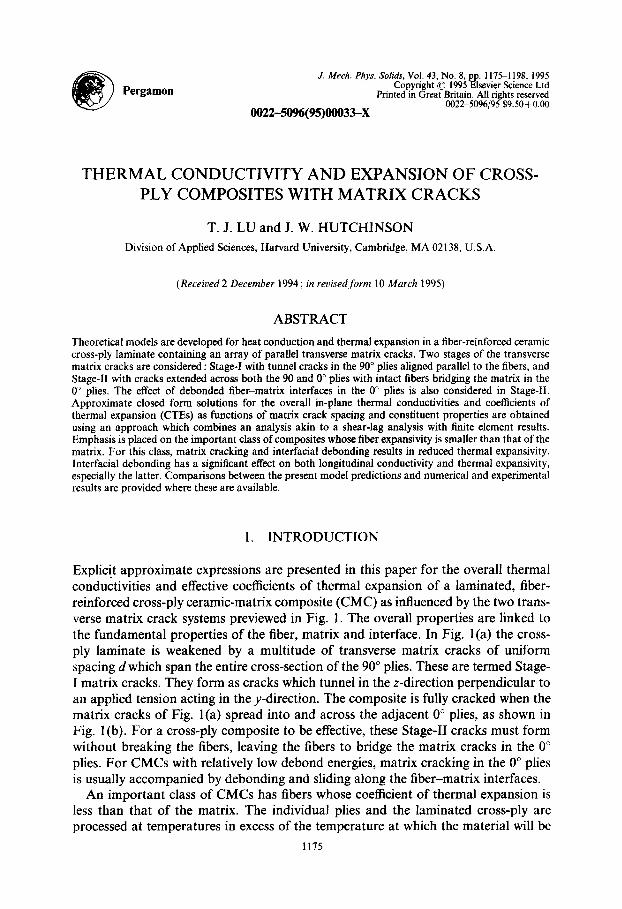
Explicit approximate expressions are presented in this paper for the overall thermal conductivities and effective coefficients of thermal expansion of a laminated, fiber- reinforced cross-ply ceramic-matrix composite (CMC) as influenced by the two trans- verse matrix crack systems previewed in Fig. 1. The overall properties are linked to the fundamental properties of the fiber, matrix and interface. In Fig. l(a) the cross- ply laminate is weakened by a multitude of transverse matrix cracks of uniform spacing d which span the entire cross-section of the 90” plies. These are termed Stage- I matrix cracks. They form as cracks which tunnel in the z-direction perpendicular to an applied tension acting in the y-direction. The composite is fully cracked when the matrix cracks of Fig. l(a) spread into and across the adjacent 0” plies, as shown in Fig. 1 (b). For a cross-ply composite to be effective, these Stage-II cracks must form without breaking the fibers, leaving the fibers to bridge the matrix cracks in the 0” plies. For CMCs with relatively low debond energies, matrix cracking in the 0” plies is usually accompanied by debonding and sliding along the fiber-matrix interfaces.
An important class of CMCs has fibers whose coefficient of thermal expansion is less than that of the matrix. The individual plies and the laminated cross-ply are processed at temperatures in excess of the temperature at which the material will be
1175
1176 T. J. LU and J. W. HUTCHINSON
, Y(2)
Fig. 1. A fiber -I reinforced cross-ply laminate with (a) Stage-I matrix cracks ; and (b) Stage. .I1 matrix cracks.
d
i d
(b)
used. The CTE mismatch between the fiber and matrix affects the behavior of the composite at two scales. Within each ply, the fiber experiences a residual compression along its axis, the matrix is in tension parallel to the fibers, while the fiber-matrix interface is subject to a residual compression. At the scale of the individual plies, the mismatch results in an average residual tensile stress acting across the 90” plies in the jj-direction in Fig. 1, and an average residual compressive stress in that same direction in the 0” plies. At the scale of the fiber within the 0” plies, the residual stresses promote matrix cracking without fiber breakage, and, when debonding occurs, the residual stresses tend to keep the interfaces closed. At the larger scale of the plies, the residual tension in the 90” plies in the y-direction adds to an applied tension in that direction to produce conditions which favor the spread of the Stage-I tunnel cracks. At higher applied tension, Stage-II cracks spread across the 0” plies. This sequence of events has been observed in SiC-CAS cross-plies loaded in tension parallel to one of the fiber directions by Beyerle et al. (1992). It has been analyzed by Xia and Hutchinson (1994).
Inspired by the first systematic study of Stage-l matrix cracks by Garrett and Bailey (1977), there has been considerable research effort devoted to the description of their effects on stiffness reduction of laminated composite materials. A collection of some
Thermal conductivity and expansion of composites 1177
important papers on the subject, both theoretical and experimental, can be found in Laws and Dvorak (1988) and McCartney (1992). More recent works in this area have been directed towards understanding the overall stress-strain behavior of cracked composite laminates as influenced by the constituent properties (Xia et al., 1993 ; Xia and Hutchinson, 1994 ; Evans et al., 1994). The effective CTEs of a cross-ply laminate in the presence of Stage-I cracks have been calculated by Bowles (1984) and Adams and Herakovich (1984), using a finite element procedure, and by Hashin (1988) on the basis of variational methods. Herakovich et al. (1988), Nairn (1989), McCartney (1992) and Gudmundson and Zang (1993) also discuss some aspects of effects of Stage-I cracks on thermal expansion, especially where they follow from a direct analog to effects on stiffness reduction.
The study in this paper has been motivated by the effort to develop CMCs for structural applications involving high temperatures and high temperature gradients where at least a limited amount of matrix cracking in the vicinity of notches, holes or other sources of stress concentrations must be contemplated for designs to be efficient. The work reported here should be regarded as a continuation of two earlier papers (Lu and Hutchinson, 1995a,b), which focused on some of the same phenomena for unidirectional fiber-reinforced composites. For simplicity, the laminated cross-plies studied here are taken to have an equal number of 0 and 90” plies, each with thickness 2t. The results presented can be easily adapted to cover laminates with unequal number, and unequal thicknesses, of 0 and 90” plies. For materials whose fibers have a smaller CTE than their matrix, the longitudinal (parallel to the fibers) and transverse CTEs of an undamaged single ply, aL and Q, respectively, are ordered according to aL < c+, causing the Stage-I matrix cracks to remain open in the absence of applied stress. As is customary now in the analysis of fiber-reinforced composite materials, the fibers are taken to be transversely isotropic (elastic moduli, CTEs and thermal conductivities), while the matrix is assumed to be isotropic.
In the sections to follow, the problems for the cross-ply containing either Stage-I or Stage-11 cracks will be solved by an approach combining modified shear-lag and finite element analyses. (For brevity of terminology, the method for solving for the overall thermal conductivity will also be referred as a “shear-lag analysis”, owing to the mathematical analogy between elasticity and heat conduction.) The explicit expressions thus obtained for the overall thermal conductivities and effective CTEs contain complete information needed for connecting to the constituent material properties, even though the expressions are relatively simple. The accuracy of the solutions will be checked against theoretical predictions and experimental data avail- able in the literature, as well as with some known limiting values when the crack spacing d diminishes to zero.
2. PRELIMINARY CONSIDERATIONS
2.1. Heat conduction laws
2.1.1. Single pIy. Let kr and ykr be the longitudinal and transverse thermal con- ductivities of the fiber, and k, be the thermal conductivity of the isotropic matrix.
1178 T. J. LU and J. W. HUTCHINSON
The longitudinal and transverse conductivities k,_ and kT of a crack-free single ply are given by
k = &,+(I -Pvhl k 7
T = Ykf(l +P)+Ml -dk (2.1)
$f(l -P)+kn(l +p) m I where p is the fiber volume fraction. The rule of mixtures shown above for kL is exact. The approximate expression for k, is obtained via an effective-medium approach analogous to the well-known self-consistent method (Christensen, 1979). It is valid for values of p up to about 0.6 (Markworth, 1993). Written in rectangular Cartesian coordinates (x,y, z) with the y-axis parallel to the fibers in the 0’ plies [Fig. 1 (a)], the heat fluxes (energy per unit area per unit time) in an undamaged 0” ply are related to the temperature gradients by Fourier’s law as
-4x = kT.r, -4y = kTJ, -qz = k,T,, (2.2)
where (qx, qu, qJ are the components of the flux vector, T,, = dT/dx, etc. The same relations apply to an undamaged 90” ply with due regard for the change in fiber orientation.
2.1.2. Cross-ply laminate. Fourier’s law of heat conduction in a crack-free cross-ply laminate reads
-9x = k:T.,, - YJ = k.: T,,.. - q; = k; T,,, (2.3)
where a quantity with superscript “0” will be used to denote a result where matrix cracking is absent. Throughout the paper, we shall, for convenience, use “thickness” (or “out-of-plane”), “longitudinal” and “transverse” to label laminate properties along x, y and z directions, respectively. In terms of ply conductivities, the overall thermal conductivities of the untracked laminate are given by
k’: = kT> k; = k,O = ;(kL+kT). (2.4)
In the presence of matrix cracking, the overall thermal conductivities of the cross-ply laminate, (k,, k,, k,), are defined by
-4: = k,T,,, -qY = k&, -q2 = k,i-,, (2.5)
where qi and ri (i = x,y, z) represent separately the heat flux intensities and tem- perature gradients averaged over the cross-ply.
2.2. Stress-strain laws
2.2.1. Single ply.In the Cartesian coordinates previously defined, the stress-strain law for a transversely isotropic, defect-free 0” ply takes the form
Thermal conductivity and expansion of composites 1179
1 VL
(2.6)
where, again, the longitudinal and transverse properties of the ply are distinguished by subscripts “L” and “T”, and AT is a temperature change measured from some conveniently chosen reference temperature. Here, pT = E,/2(1 +I+), but, in general, pL # EL/2( 1 + vJ. With due regard for the two orientations, these relations also hold for an untracked 90” ply. Throughout the paper identical Poisson ratios for the fiber and matrix are adopted such that vL = vr = v ( = vf = v,). The accuracy of our end results is quite insensitive to this assumption, but the algebraic simplification achieved makes it worthwhile.
The analysis of the effective CTEs requires knowledge of the in-plane moduli of the ply in terms of fiber and matrix properties. The expressions employed here are (Whitney, 1967) :
E
=
= (EfIEm + 2~) + 2dEfIEm - vl) E
(EfI4-o + 2~) - p@r/Em - rl) m EL = pEf+U-pP)Em I 3 (2.7)
PfU +P)+/4n(1-P) llL =CLf(1-P)+L4n(l+P)pm
I
where q is the ratio of axial fiber modulus relative to that in the radial direction. The CTEs of an untracked single ply, aL and Q, have been given by Hashin and Rosen (1965) and later by Lu and Hutchinson (1995a) in a more explicit form for fibers with arbitrary cylindrical anisotropy. For isotropic fibers, they are (Lu and Hutchinson, 1995a)
a =a +&AU L m EL
aT = paf+(l -p)cr,-Adcl p(1 -p)(Er-E,)[vEf+(3v-2)&1 ’
(2.8)
E,IEf+(l -W%_l
where Ef and af denote separately the Young’s modulus and thermal expansivity of the fiber, and Aa = elf-a, represents the thermal expansion mismatch. From relations (2.7) and (2.8) one can easily verify that EL is always larger than ET if q > 1. Moreover, the condition &r > gL, which ensures that the transverse matrix cracks remain open
1180 T. J. LU and J. W. HUTCHINSON
even at zero applied stress, is always satisfied if the fiber CTEs do not exceed that of the matrix in magnitude.
2.2.2. Cross-ply laminate. Refer to the coordinates defined in Fig. 1, the stress- strain law for an orthotropic, damage-free cross-ply composite reads as
(2.9)
A conventional analysis based on the assumption that the in-plane strains are identical in every ply of a crack-free cross-ply laminate yields (with equal numbers of plies of each orientation and equal thicknesses assumed)
(1 + EL/ET)’ -4~: E; = ET, E.; = E,O = ---
2(1+ EL/J%)(&/& - v:)
E
L
O- 2vL v;( 1 - EL/‘ET)’ vg* -
I+ EL/ET "" = "' = "+ 2(1+E,.,ET)(E,_,ET-v:) ' (2.10a)
and
a: = aT - vL [(l+vL~)(.Os)i(l+vL)(a~-aL)] I- v:&IEL
a; = a: = 2(EP/EL~(;~;;ET,E,)[aL(1+vL~)+aT’1+vL)~] . (2. I Ob)
For the most common CMC systems with q > I and ar < a,,,, one can see from these relations that
E,_>E;>E,=E:, 3~;>,q>r;. (2.11)
For CMCs whose fiber properties do not differ significantly from those of the matrix, the above expressions for undamaged laminate properties can be well approximated
by
Thermal conductivity and expansion of composites 1181
0 0 2 4
WJL 6 6 10
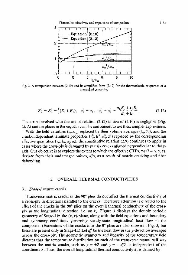
Fig. 2. A comparison between (2.10) and its simplified form (2.12) for the thermoelastic properties of a untracked cross-ply.
E,O = E,O =i(EL+ET), a: = aT, a: = a: = aLEL + aTET E +E .
L T
(2.12)
The error involved with the use of relation (2.12) in lieu of (2.10) is negligible (Fig. 2). At certain places in the sequel, it will be convenient to use these simpler expressions.
With the field variables (Q, oj,> replaced by their volume averages (Zij, a,), and the crack-independent laminate properties (v;, EQ, &, a:) replaced by the corresponding effective quantities (vi,, Ei, pij, ai), the constitutive relation (2.9) continues to apply in cases where the cross-ply is damaged by matrix cracks aligned perpendicular to the y- axis. Our objective is to explore the extent to which the effective CTEs, a,s (i = x, y, z), deviate from their undamaged values, ass, as a result of matrix cracking and fiber debonding.
3. OVERALL THERMAL CONDUCTIVITIES
3.1. Stage-I matrix cracks
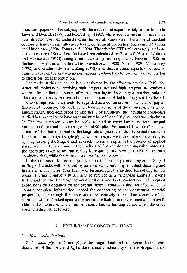
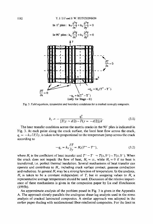
Transverse matrix cracks in the 90” plies do not affect the thermal conductivity of a cross-ply in directions parallel to the cracks. Therefore attention is directed to the effect of the cracks in the 90” plies on the overall thermal conductivity of the cross- ply in the longitudinal direction, i.e. on k,. Figure 3 displays the doubly periodic geometry of Stage-I in the (x, y)-plane, along with the field equations and boundary and symmetry conditions governing steady-state longitudinal heat flow in the composite. (Extensions of the cracks into the 0” plies are also shown in Fig. 3, but these are present only in Stage-II.) Let q,” be the heat flow in the y-direction averaged across the cross-ply. The geometric symmetry and linearity of the temperature field dictates that the temperature distribution on each of the transverse planes half way between the matrix cracks, such as y = d/2 and y = -d/2, is independent of the coordinate x. Thus, the overall longitudinal thermal conductivity k, is defined by
1182 T. J. LU and J. W. HUTCHINSON
In 0” plies :
In90” plies: kLs+kT- - 0 ay2 -
I
I
I :I I
I
I
I
I
I I II I
I
I
I
aT W’ TIT= 0 OX
\, -qy = H,(T+ -T-)
-qy = h(T’ -T-) (only for Stage -II)
1 _I_
I
I
t I
I I
I
I
t
I I I I
I
I
---_ k
aT d,‘O
J -s-e
-2
Fig. 3. Field equations, symmetries and boundary conditions for a cracked cross-ply composite.
0
ky = - [T(y = d/2)-F(y = -d/2)]/d‘ (3.1)
The heat transfer condition across the matrix cracks in the 90” plies is indicated in Fig. 3. At each point along the crack surface, the local heat flow across the crack, qy = -kTaT/ay, t k t b is a en o e proportional to the temperature jump across the crack according to
-q,, = k,$= Hc(T+ -T-), (3.2)
where H, is the coefficient of heat transfer and T+ - T- = T(x, O+) - T(x, O-). When the crack does not impede the flow of heat, H, = co, while H, = 0 if no heat is transferred, i.e. perfect thermal insulation. Several mechanisms of heat transfer can operate and contribute to H,, including crack surface contact, gaseous conduction and radiation. In general H, may be a strong function of temperature. In the analysis, H, is taken to be a constant independent of T, but in assigning values to H, a
representative average temperature should be used. Discussion of the relative import- ance of these mechanisms is given in the companion paper by Lu and Hutchinson (1995b).
An approximate analysis of the problem posed in Fig. 3 is given in the Appendix A. The approach closely parallels the analogous shear-lag analysis used in the stress analysis of cracked laminated composites. A similar approach was adopted in the earlier paper dealing with unidirectional fiber-reinforced composites. For the limit in
1183 Thermal conductivity and expansion of composites
0 .5 1 t/d
1.5 2 2.5
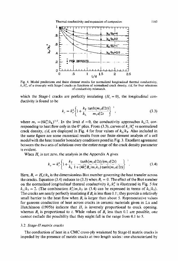
Fig. 4. Model predictions and finite element results for normalized longitudinal thermal conductivity, k,/ki, of a cross-ply with Stage-I cracks as functions of normalized crack density, t/d, for four selections
of conductivity mismatch.
which the Stage-I cracks are perfectly insulating (Hc = 0), the longitudinal con- ductivity is found to be
(3.3)
where m, = (6k,O/k,)“‘. In the limit d -+ 0, the conductivity approaches kL/2, cor- responding to heat flow only in the 0” plies. From (3.3), curves of k,,,/k,O vs normalized crack density, t/d, are displayed in Fig. 4 for four values of kL/kT. Also included in the same figure are some numerical results from our finite element analysis of a cell model with the heat transfer boundary conditions posed in Fig. 3. Excellent agreement between the two sets of solutions over the entire range of the crack density parameter is evident.
When H, is not zero, the analysis in the Appendix A gives
tanh(m, d/2t)/(m, d/2t) ~ ’
kL 1 + (4k,OB,/m, kT) tanh(m, d/2t) . (3.4)
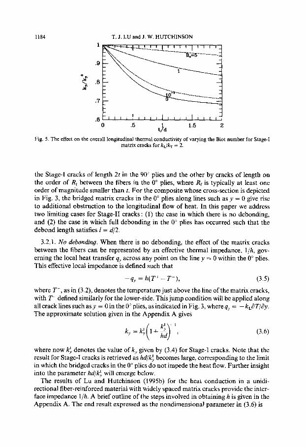
Here, B, = Hct/kL is the dimensionless Biot number governing the heat transfer across the cracks. Equation (3.4) reduces to (3.3) when B, = 0. The effect of the Biot number on the normalized longitudinal thermal conductivity k,/k~z is illustrated in Fig. 5 for k,/k, = 2. (The combination k,O/m,kT in (3.4) can be expressed in terms of kL/kT). The cracks are nearly perfectly insulating if B, is less than 0.1; they provide a relatively small barrier to the heat flow when B, is larger than about 5. Representative values for gaseous conduction of heat across cracks in ceramic materials given in Lu and Hutchinson (1995b) indicate that H, is inversely proportional to crack opening, whereas B, is proportional to t. While values of B, less than 0.1 are possible, one cannot exclude the possibility that they might fall in the range from 0.1 to 5.
3.2. Stage-II matrix cracks
The conduction of heat in a CMC cross-ply weakened by Stage-II matrix cracks is impeded by the presence of matrix cracks at two length scales : one characterized by
1184 T. J. LU and J. W. HUTCHINSON
0 5 f
1.5 2 td
Fig. 5. The effect on the overall longitudinal thermal conductivity of varying the Biot number for Stage-I matrix cracks for k&, = 2.
the Stage-I cracks of length 2t in the 90” plies and the other by cracks of length on the order of Rf between the fibers in the 0” plies, where Rf is typically at least one order of magnitude smaller than t. For the composite whose cross-section is depicted in Fig. 3, the bridged matrix cracks in the 0” plies along lines such as y = 0 give rise to additional obstruction to the longitudinal flow of heat. In this paper we address two limiting cases for Stage-II cracks : (1) the case in which there is no debonding, and (2) the case in which full debonding in the 0” plies has occurred such that the debond length satisfies 1 = d/2.
3.2.1. No debonding. When there is no debonding, the effect of the matrix cracks between the fibers can be represented by an effective thermal impedance, l/h, gov- erning the local heat transfer qy across any point on the line y = 0 within the 0” plies. This effective local impedance is defined such that
-qy = h(T+ -T-J (3.5)
where T+, as in (3.2), denotes the temperature just above the line of the matrix cracks, with T- defined similarly for the lower-side. This jump condition will be applied along all crack lines such as y = 0 in the 0” plies, as indicated in Fig. 3, where qy = - k,~? T/@. The approximate solution given in the Appendix A gives
(3.6)
where now k: denotes the value of k, given by (3.4) for Stage-I cracks. Note that the result for Stage-I cracks is retrieved as hd/kh becomes large, corresponding to the limit in which the bridged cracks in the 0” plies do not impede the heat flow. Further insight into the parameter hd/k: will emerge below.
The results of Lu and Hutchinson (1995b) for the heat conduction in a unidi- rectional fiber-reinforced material with widely spaced matrix cracks provide the inter- face impedance l/h. A brief outline of the steps involved in obtaining h is given in the Appendix A. The end result expressed as the nondimensional parameter in (3.6) is
Thermal conductivity and expansion of composites
, ,,, ,,, ,,, ,,,
B,,=O.l
1185
-0 2 .4 t/d
.6 .8 1
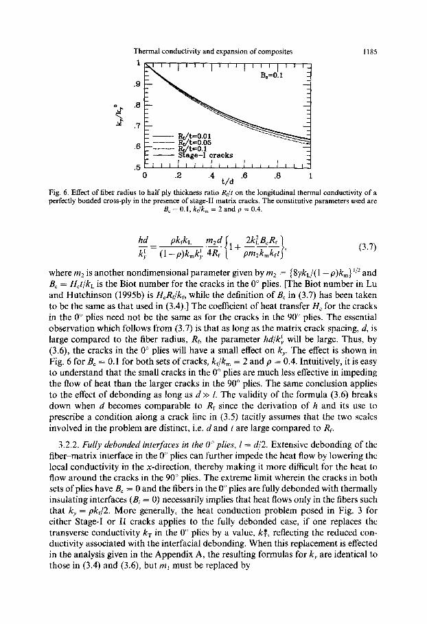
Fig. 6. Effect of fiber radius to half ply thickness ratio Rf/t on the longitudinal thermal conductivity of a perfectly bonded cross-ply in the presence of stage-II matrix cracks. The constitutive parameters used are
B, = 0.1, kc/k, = 2 and p = 0.4.
hd PkfkL -_= k; (1-p)k,k;
(3.7)
where m2 is another nondimensional parameter given by m2 = (8yk,/( 1 - p)k,,J ‘j2 and B, = Hct/kL is the Biot number for the cracks in the 0” plies. [The Biot number in Lu and Hutchinson (1995b) is HCRf/kf, while the definition of B, in (3.7) has been taken to be the same as that used in (3.4).] The coefficient of heat transfer H, for the cracks in the 0” plies need not be the same as for the cracks in the 90” plies. The essential observation which follows from (3.7) is that as long as the matrix crack spacing, d, is large compared to the fiber radius, Rf, the parameter hd/k: will be large. Thus, by (3.6), the cracks in the 0” plies will have a small effect on k,. The effect is shown in Fig. 6 for B, = 0.1 for both sets of cracks, kdk,,, = 2 and p = 0.4. Intuitively, it is easy to understand that the small cracks in the 0” plies are much less effective in impeding the flow of heat than the larger cracks in the 90” plies. The same conclusion applies to the effect of debonding as long as d >> 1. The validity of the formula (3.6) breaks down when d becomes comparable to Rf since the derivation of h and its use to prescribe a condition along a crack line in (3.5) tacitly assumes that the two scales involved in the problem are distinct, i.e. d and t are large compared to Rf.
3.2.2. Fully debonded interfaces in the 0” plies, I= d/2. Extensive debonding of the fiber-matrix interface in the 0” plies can further impede the heat flow by lowering the local conductivity in the x-direction, thereby making it more difficult for the heat to flow around the cracks in the 90” plies. The extreme limit wherein the cracks in both sets of plies have B, = 0 and the fibers in the 0” plies are fully debonded with thermally insulating interfaces (B; = 0) necessarily implies that heat flows only in the fibers such that k, = pk,/2. More generally, the heat conduction problem posed in Fig. 3 for either Stage-I or II cracks applies to the fully debonded case, if one replaces the transverse conductivity kT in the 0” plies by a value, kf, reflecting the reduced con- ductivity associated with the interfacial debonding. When this replacement is effected in the analysis given in the Appendix A, the resulting formulas for k, are identical to those in (3.4) and (3.6) but m, must be replaced by
1186 T. J. LU and J. W. HUTCHINSON
0 .2 A t/d
.f3 .a 1
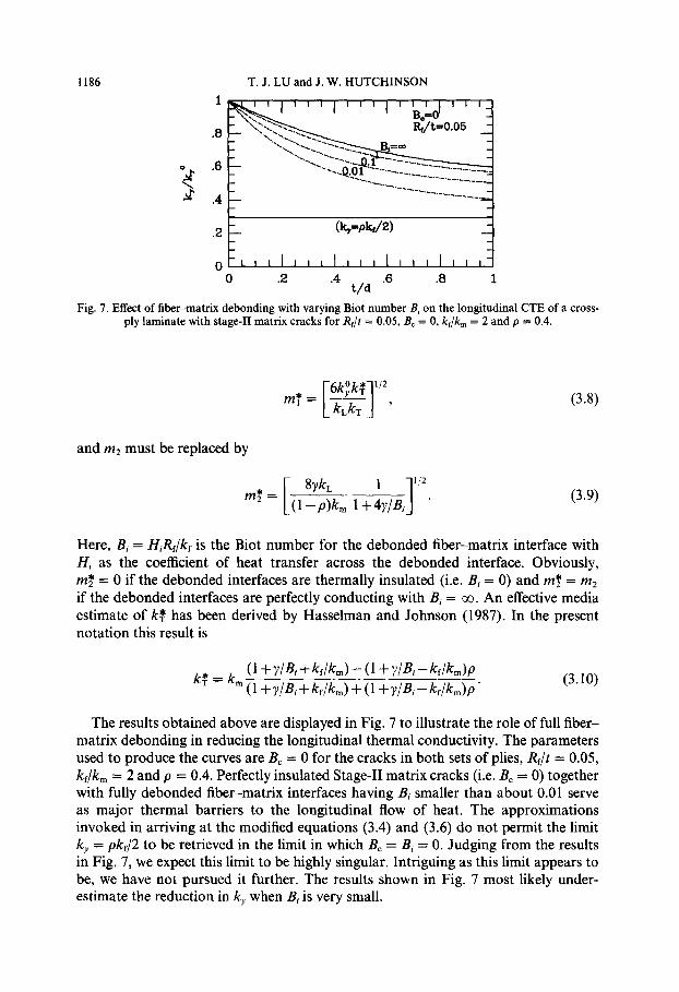
Fig. 7. Effect of fiber-matrix debonding with varying Biot number B, on the longitudinal CTE of a cross- ply laminate with stage-11 matrix cracks for R& = 0.05, B, = 0, kf/km = 2 and p = 0.4.
and m2 must be replaced by
8&_ 1
3
l/2
m’ = (1-p)k, 1+4y/Bi ’
(3.8)
(3.9)
Here, Bi = HiRJk, is the Biot number for the debonded fiber-matrix interface with Hi as the coefficient of heat transfer across the debonded interface. Obviously, rnf = 0 if the debonded interfaces are thermally insulated (i.e. Bi = 0) and rnf = m2 if the debonded interfaces are perfectly conducting with Bi = co. An effective media estimate of k; has been derived by Hasselman and Johnson (1987). In the present notation this result is
(3.10)
The results obtained above are displayed in Fig. 7 to illustrate the role of full fiber- matrix debonding in reducing the longitudinal thermal conductivity. The parameters used to produce the curves are B, = 0 for the cracks in both sets of plies, R$t = 0.05, kf/k, = 2 and p = 0.4. Perfectly insulated Stage-II matrix cracks (i.e. B, = 0) together with fully debonded fiber-matrix interfaces having Bi smaller than about 0.01 serve as major thermal barriers to the longitudinal flow of heat. The approximations invoked in arriving at the modified equations (3.4) and (3.6) do not permit the limit k, = pkJ2 to be retrieved in the limit in which B, = Bi = 0. Judging from the results in Fig. 7, we expect this limit to be highly singular. Intriguing as this limit appears to be, we have not pursued it further. The results shown in Fig. 7 most likely under- estimate the reduction in k, when Bi is very small.
Thermal conductivity and expansion of composites 1187
4. EFFECTIVE CTES
4.1. Stage-I matrix cracks
For fiber-matrix thermal mismatches such as those discussed in the Introduction, the Stage-I cracks shown in Fig. 1 (a) are open as long as the temperature T is below the temperature at which the composite was processed. With AT as the temperature change relative to some conveniently chosen reference, the effective coefficients of thermal expansion of the cross-ply are denoted by LY,, OLD, c(,, such that or,AT denotes the longitudinal strain change due to the temperature change from the reference, and similarly for the other components. The expressions for the CTEs of an untracked cross-ply are denoted by a superscript “0” and are given in (2. lob) and in a simplified form in (2.12). The overall strain changes in the cracked cross-ply are readily defined. For example, with reference to Fig. 1 (a), the displacement component U, along planes such as y = + d/2 is independent of x, by symmetry, and therefore & = (u,(d/2) - uI
(- d/2))ld. It is well-known that one can relate the effect of cracks on the CTEs directly to the
increase in compliance due to the cracks. This connection will be exploited here. We also note the close mathematical analogy between the problem for the CTEs and the heat conduction problem considered in Section 3. The expressions for the effect of the cracks on the CTEs turn out to be more complicated than those for the heat conduction coefficients because of Poisson ratio effects. Nevertheless, this close math- ematical analogy, together with the parallel analysis for the CTEs of a cracked unidirectional composite (Lu and Hutchinson, 1995a), permits us to omit the some- what more lengthy details of the shear-lag analysis leading to the expressions given below. Following the presentation of the results, a comparison with results of other authors on the effect of Stage-I cracks will be made.
A necessary starting point in the presentation is the connection between the effect of cracks on compliance change and on change in longitudinal CTE. The change in overall stiffness of the composite with cross-sectional geometry shown in Fig. l(a) can be written in the form
1 1
E,=s ( 1 l.C,f ) (4.3)
where C, is a dimensionless function of t/d and the dimensionless moduli combi- nations. Because of the connection between the thermal expansion problem and the compliance problem, one can also express q in terms of C, as
The simplified expression for E,f in (2.12) was used in arriving at (4.4) otherwise the connection between (4.3) and (4.4) is exact. Numerical values for C, can be obtained from the extensive results in Xia et al. (1993) who used a finite element method to compute the compliance change due to Stage-I cracks. The results of the present shear-lag analysis suggest the following approximation for C, :

1188 T. J. LU and J. W. H KJTCHINSON
.8
.4
.2
Fig. 8. Numerical results for Cy as function of (a) Ef/Em ; and (b) EL/ET.
(4.5)
where Cy must be obtained numerically. From (4.3), Cy can be seen to represent the compliance change when the matrix cracks are widely spaced (i.e. d > 3t). The coefficient Cy has been extracted from the numerical results of Xia et al. (1993). It depends very weakly on p but fairly strongly on E,IE,,,, as can be seen in Fig. 8(a). Here, both the fiber and matrix were taken to be isotropic with v = 0.2, although the influence of Poisson’s ratio on Cy was found to be very small. The results of Fig. 8(a) are replotted as a function of EL/ET in Fig. 8(b). For fibers with arbitrary cylindrical anisotropy, one can use (2.7) to calculate EL/ET and extract the corresponding Cy from Fig. 8(b).
Approximate expressions for the transverse CTEs, ~1, and CI,, can also be derived using an approach such as that given by McCartney (1992). However, because the effect of the cracks on the transverse CTEs is quite small as long as Ef/E,,, < 10, which is almost always the case for CMCs, we will not present results for the transverse CTEs.
In Fig. 9(a), the effective longitudinal CTE, a,,, for a [0,/90,], T300/5208 graphite- epoxy cross-ply as a function of the crack density parameter, t/d, is plotted using relation (4.4), where it is compared with the finite element results of Bowles (1984). The effect is large because the longitudinal CTE of the fiber is small compared to the
Thermal conductivity and expansion of composites 1189
0 .2 .4 t/d
.6 .8 1
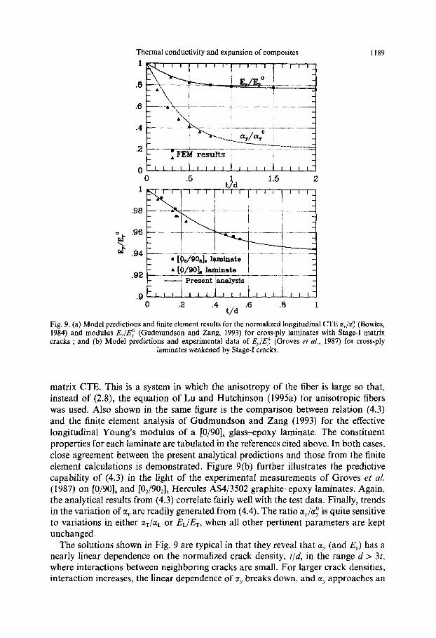
Fig. 9. (a) Model predictions and finite element results for the normalized longitudinal 1984) and modulus E,/Ei (Gudmundson and Zang, 1993) for cross-ply laminates cracks ; and (b) Model predictions and experimental data of E,/Ez (Groves et al.,
laminates weakened by Stage-I cracks.
CTE a,/a,” (Bowles, with Stage-I matrix 1987) for cross-ply
matrix CTE. This is a system in which the anisotropy of the fiber is large so that, instead of (2.8), the equation of Lu and Hutchinson (1995a) for anisotropic fibers was used. Also shown in the same figure is the comparison between relation (4.3) and the finite element analysis of Gudmundson and Zang (1993) for the effective longitudinal Young’s modulus of a [O/90], glass-epoxy laminate. The constituent properties for each laminate are tabulated in the references cited above. In both cases, close agreement between the present analytical predictions and those from the finite element calculations is demonstrated. Figure 9(b) further illustrates the predictive capability of (4.3) in the light of the experimental measurements of Groves et al.
(1987) on [O/901s and [0,/90,], Hercules AS4/3502 graphite-epoxy laminates. Again, the analytical results from (4.3) correlate fairly well with the test data. Finally, trends in the variation of ay are readily generated from (4.4). The ratio c+$! is quite sensitive to variations in either a,/~, or EL/ET, when all other pertinent parameters are kept unchanged.
The solutions shown in Fig. 9 are typical in that they reveal that 01~ (and E,) has a nearly linear dependence on the normalized crack density, t/d, in the range d > 31, where interactions between neighboring cracks are small. For larger crack densities, interaction increases, the linear dependence of ~1, breaks down, and a, approaches an
1190 T. J. LU and J. W. HUTCHINSON
asymptotic limit when d + 0. From (4.4) this limiting value of aY is not a,_ but rather aL + v(aT - aJ/(l + EL/ET) (to a good approximation), due to a Poisson constraint in the z-direction exerted by the 90” layers on the 0” layers. The 0” plies are not free to undergo unconstrained expansion in the z-direction (governed by aT) because the 90” plies have a different CTE (i.e. aL) in the same direction. Since the crack planes in the 90” plies lie parallel to the z-direction, the constraint persists even when the crack density becomes large. The analyses of Hashin (1985, 1988) and Nairn (1989) do not capture this effect. The analyses of these authors predict that clY should approach CI~ as d vanishes. Nairn attributes ad arbitrium the discrepancy between this limit and the finite element predictions of Bowles (1984) and Adams and Herakovich (1984) for large crack densities (which, indeed, indicate a limit larger than a,_ for the case studied with CI~ > MJ to the inability of the finite element analysis to treat highly cracked 90” layers.
4.2. Stage-II matrix cracks
4.2.1. Perfect bonding. For the Stage-II problem, the matrix cracks in the 0” plies are bridged by the fibers. With oYv as the local normal stress in the 0” plies just above (and below) the crack plane, the additional displacement in the y-direction arising from the presence of the matrix crack can be represented as a linear “spring” according to
Au, E u,(x,O+)-uJx,O-) D:&
=?cr Y)” L
(4.6)
The dimensionless coefficient D y, which was computed on the basis of a cylindrical cell model by He et al. (1994), is a function of EfiE,,, and p, as plotted in Fig. 10. Thus, the model for the Stage-II cracks has the cross-sectional geometry shown in Fig. 1 (b). The planes such as y = 0, which coincide with the matrix cracks in the 0” plies, are bridged by a continuous distribution of linear springs specified by (4.6). For this model, a connection generalizing that in (4.3) and (4.4) between the compliance and the coefficient of thermal expansion can be obtained. The connection must now reflect the effect of both the cracks in the 90” plies and those in the 0” plies modeled by (4.6).
The shear-lag analysis for the compliance of this model gives
1 1 -=- EY E,O
l+C,;+2D$$, L 1
with C, still given by (4.5). As in the case of the corresponding thermal conductivity problem, the modeling leading to this result is only meaningful when d is large compared to R,. The connection between the thermal expansion problem and the compliance problem is through the local stresses in the matrix in the 0” plies before cracking occurs. The stress due to an average applied stress b, in the 0” ply is
cm =(l -alp)G/(l -P), (4.8)
while the residual stress due to temperature change AT is
CL, = paz&(af-GAT/(l -P), (4.9)
Thermal conductivity and expansion of composites 1191
51 , I , , , , , , , , , , , , ,rr,,,,“rl
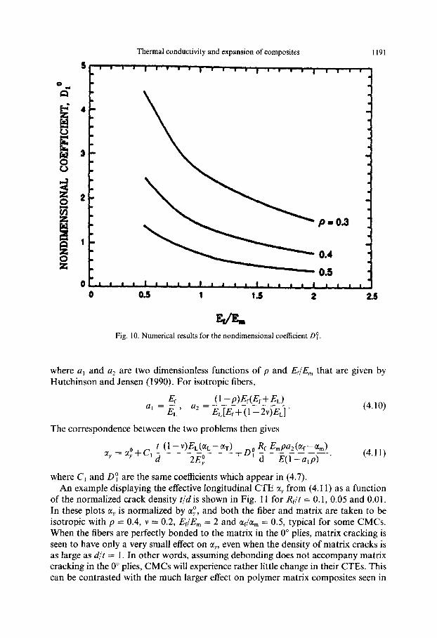
Fig. 10. Numerical results for the nondimensional coefficient 0:.
where a, and a2 are two dimensionless functions of p and Ef/E, that are given by Hutchinson and Jensen (1990). For isotropic fibers,
Ef (1 -P)E@,+&) a,=-, a*=
EL E&+(1 -2v)EJ ’ (4.10)
The correspondence between the two problems then gives
t (1 -WL(~L-@T) a, = a;+c, - & Em pa2 C&f - G,>
d 2Ej +DY-
d E(l-a,~) ’ (4.11)
where C, and 0: are the same coefficients which appear in (4.7). An example displaying the effective longitudinal CTE @Y from (4.11) as a function
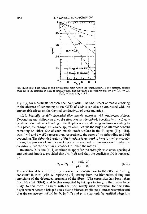
of the normalized crack density t/d is shown in Fig. 11 for RJt = 0.1, 0.05 and 0.01. In these plots ol, is normalized by LX,“, and both the fiber and matrix are taken to be isotropic with p = 0.4, v = 0.2, EfIE,,, = 2 and Q/U, = 0.5, typical for some CMCs. When the fibers are perfectly bonded to the matrix in the 0” plies, matrix cracking is seen to have only a very small effect on q, even when the density of matrix cracks is as large as d/t = I. In other words, assuming debonding does not accompany matrix cracking in the 0” plies, CMCs will experience rather little change in their CTEs. This can be contrasted with the much larger effect on polymer matrix composites seen in
1192 T. J. LU and J. W. HUTCHINSON
l~,,,,,,,,,,,,,,,l’l
.- 0 .2 .4 t/&8 .8 1
Fig, 11. Effect of fiber radius to half ply thickness ratio Rf/t on the longitudinal CTE of a perfectly bonded cross-ply in the presence of stage-II matrix cracks. The constitutive parameters used are p = 0.4, v = 0.2,
Ef/Em = 2 and ada, = 0.5.
Fig. 9(a) for a particular carbon fiber composite. The small effect of matrix cracking in the absence of debonding on the CTEs of CMCs can also be contrasted with the appreciable effects on the thermal conductivity of these materials.
4.2.2. Partially or fully debonded Jiber-matrix interface with frictionless sliding. Debonding and sliding can alter the situation just described. Specifically, it will now be shown that when debonding in the 0” plies occurs, allowing frictionless sliding to take place, the change in CI, can be appreciable. Let 1 be the length of interface debond extending on either side of each matrix crack surface in the 0” layers [Fig. l(b)], with 1 = 0 and I= d/2 representing, respectively, the cases of no debonding and full debonding. The debonded region of the interface is assumed to have formed previously during the process of matrix cracking and is assumed to remain closed under the conditions that the fiber has a smaller CTE than the matrix.
Relations (4.7) and (4.11) continue to apply for the cross-ply with crack spacing d and debond length 1, provided that 1~ (t, d) and that the coefficient 0: is replaced
by
D 1
= D0+ (I-P)J% 21 1
PJ% Rf ’ (4.12)
The additional term in this expression is the contribution to the effective “spring constant” in (4.6) (with D, replacing Dy) arising from the frictionless sliding and stretching of the debonded segments of the fibers. (The expression has been taken from He et al. (1994), and further simplified by taking a factor x in that paper to be unity. In this form it agrees with the most widely used expression for the extra displacement across a bridged crack due to frictionless sliding.) It must be emphasized that the replacement of 0: by DI in (4.7) and (4.11) can only be justified when it is
Thermal conductivity and expansion of composites 1193
legitimate to model the effect of the debonded fibers as a line-spring, that is when z<< (t,d).
When the fiber-matrix interfaces are fully debonded (Z = d/2), the longitudinal CTE of the cross-ply is dominated by the CTE of the fibers in the 0” ply and is weakly dependent on the crack spacing d. Neglecting the Poisson constraint effect exerted by the 90” ply on the expansion of the 0” ply in the z-direction but accounting for the Poisson interaction in the radial direction between the fiber and matrix in the 0” plies, we arrive at (Lu and Hutchinson, 1995a)
AU CI,, = c(~ +4a,p’c: ___
1 -a,p’ (4.13)
where the dimensionless coefficient c,, as a, and a2, was introduced in Hutchinson and Jensen (1990). For isotropic fibers, the laminate CTE mY becomes
(1 -P)&&+EL) ay = ML+(af-G1”)EL(Ef+(1_2v)EL)’ (4.14)
It can be readily verified from (2.8) and (4.14) that rxY = c(~ if the Poisson ratio v = 0. In general, av is slightly smaller than tlf due to Poisson interaction between the fiber and the matrix. (Recall, again, that the residual stresses are such that the fiber-matrix interface remains closed.) This approximate result does not depend on the matrix crack spacing. Guidance as to how frictional sliding resistance alters these results can be obtained from the study of unidirectional reinforcement in Lu and Hutchinson (1995a).
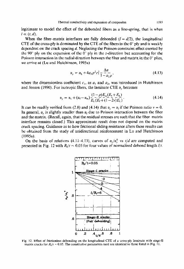
On the basis of relations (4.1 l-4.13) curves of a&j vs t/d are computed and presented in Fig. 12 with RJt = 0.05 for four values of normalized debond length Z/t.
0 2 .4 t/d
.6 .6 1
Fig. 12. Effect of frictionless debonding on the longitudinal CTE of a cross-ply laminate with stage-11 matrix cracks for RJt = 0.05. The constitutive parameters used are identical to those listed in Fig. II.
1194 T. J. LU and J. W. HUTCHINSON
The same choice of parameters is employed as in Fig. 11, namely p = 0.4, v = 0.2, Ef/Em = 2 and cl&, = 0.5. Note that the scale of the ordinate is much larger in Fig. 12 than in Fig. 11. Debonding clearly has a major effect on CX~. Also included in Fig. 12 is the prediction from (4.14) for fully debonded stage-II matrix cracking. The value for aY from (4.14) in this example is 0.88 elf, which falls below af for reasons discussed above.
Finally, we note that the procedures used to estimate the increase of compliance due to matrix cracking in a cross-ply can be applied to calculate the average longi- tudinal stress acting on the 0” plies when the cracked cross-ply is loaded in the y- direction. An analysis leading to closed form formulas for this average stress quantity is given in Appendix B for both Stage-I and Stage-II matrix cracks. The results obtained can be applied to simulate the stress-strain curves of cross-ply composites in a way described by Evans et al. (1994).
5. CONCLUSIONS
The changes in thermal conductivities and coefficients of thermal expansion due to matrix cracking and interfacial debonding in cross-ply CMCs have been analyzed, with emphasis placed on composite systems where the CTE of the matrix is larger than that of the fiber. Realistic densities of Stage-I cracks result in significant reduction in the overall longitudinal thermal conductivity but have a rather small effect on the CTEs of ceramic cross-plies. This is in contrast to the appreciable changes Stage-I cracks produce in the longitudinal CTE of certain polymer-matrix composite systems where the fiber expansivity is much smaller than that of the matrix. When fiber- matrix debonding does not accompany matrix cracking in the 0” plies, Stage-II cracking produces only small incremental changes from Stage-I cracking, as far as the overall conductivities and expansivities are concerned. Debonding and sliding of the fiber-matrix interfaces in the 0” plies produces substantial changes from the Stage- I values. The combination of matrix cracking and interfacial debonding can reduce the longitudinal thermal conductivity k, and CTE CI, of the cracked cross-ply to levels close to pk$2 and uf, respectively. The properties of the cross-ply in the other two directions are much less affected by the presence of matrix cracks under the conditions that perfect bonding exists between the fiber and the matrix. Debonding does change the transverse thermal conductivity, but in a manner which is not influenced by the existence of the matrix cracks.
ACKNOWLEDGMENTS
The work reported here was partially supported by the ARPA University Initiative ONR Prime Contract N00014-92-J-1808, and by the Division of Applied Sciences, Harvard Univer- sity. The commercial ABAQUS finite element code was used in carrying out some of the numerical computations.
REFERENCES
Adams, D. S. and Herakovich, C. T. (1984) Influence of damage on the thermal response of graphiteepoxy laminates. J. Thermal Stresses 7,91-103.
Thermal conductivity and expansion of composites 1195
Beyerle. D. S., Spearing, S. M. and Evans, A. G. (1992) Damage and failure in unidirectional ceramic-matrix composites. J. Am. Cerum. Sot. 75, 332 l-3330.
Bowles, D. E. (1984) Effect of microcracks on the thermal expansion of composite laminates. J. Comp. Mater. 17, 173-187.
Christensen, R. M. (1979) Mechanics of’ Composite Materials. Wiley, New York. Evans. A. G., Domergue. J.-M. and Vagaggini, E. (1994) Methodology for relating the tensile
constitutive behavior of ceramic-matrix composites to constituent properties. J. Am. C’ercrm. SW. 77, 1425. 1435.
Garrett. K. W. and Bailey, J. E. (1977) Multiple transverse fracture in 90 cross-ply laminates of a glass fiber-reinforced polyester. J. Mater. Sci. 12, 157-168.
Groves. S. E.. Harris. C. E., Highsmith, A. L.. Allen, D. H. and Norvell, R. G. (1987) An experimental and analytical treatment of matrix cracking in cross-ply laminates. E.upl. Mwh. 27, 73 -79.
Gudmundson, P. and Zang, W. (1993) An analytical model for thermoelastic properties of composite laminates containing transverse matrix cracks. ht. J. Solids Strut. 30, 321 l-323 I.
Hashin. Z. ( 1985) Analysis of cracked laminates : a variational approach. Me&. Mtirer. 4, 12 I - 136.
Hashin. Z. (1988) Thermal expansion coefficients of cracked laminates. C’onrp. Sci. Tech. 31, 247-260.
Hassrlman. D. P. H. and Johnson, L. F. (1987) Effective thermal conductivity of composites with interfacial thermal barrier resistance. J. C‘omp. Mater. 21, 508 -514.
He. M. Y., Wu. B.-X.. Evans, A. G. and Hutchinson, J. W. (1994) Inelastic strains due to matrix cracking in unidirectional fiber-reinforced composites. Mech. Muter. 18, 213-22’).
Herakovich. C. T.. Aboudi, J., Lee, S. W. and Strauss. E. A. (1988) Damage in composite laminates : effects of transverse cracks. Mech. Mater. 7, Y I- 107.
Hutchinson, J. W. and Jensen. H. M. (1990) Models of fiber debonding and pullout in brittle composites with friction. Mech. Mater. 9, l39- 163.
Laws. N. and Dvorak, G. J. (1988) Progressive transverse cracking in composite laminates. J. (‘amp. Mater. 22, 900-Y 16.
Lu. T. J. and Hutchinson, J. W. (lY95a) Effect of matrix cracking and interface sliding on the thermal expansion of fiber-reinforced composites. Composites 26 (in press).
Lu. T. J. and Hutchinson, J. W. (IYYSb) Effect of matrix cracking on the overall thermal conductivity of fiber-reinforced composites. Phil. Trons. Ro!,. Sock. I,ond. (in press).
McCartney. L. N. (1992) Theory of stress transfer in a 0 -90 0 cross-ply laminate containing a parallel array of transverse cracks. J. Mech. Ph~~s. So/ids 40, 2768.
Markworth, A. J. (1993) The transverse thermal conductivity ofa unidirectional fiber composite with fiber -matrix debonding : a calculation based on effective-medium theory. J. Mater. Sci. Lett. 12, 14X7-1489.
Nairn, J. A. (1989) The strain energy release rate of composite microcracking: a variational approach. J. Camp. Mater. 23, 11061129.
Whitney. J. M. (1967) Elastic moduli of unidirectional composites with anisotropic filaments. J. Camp. Muter-. I, 18% 193.
Xia. 1.. c‘. and Hutchinson, J. W. (1994) Matrix cracking of cross-ply ceramic composites. Arta Metall. Mater. 42, 1933- 1945.
Xia. Z. C.. Carr. R. R. and Hutchinson, J. W. (I 993) Transverse cracking in fiber-reinforced brittle matrix. cross-ply laminates. Acta Metull. Muter. 41, 2365 2376.
APPENDIX A : “SHEAR-LAG” ANALYSIS OF HEAT CONDUCTION IN CROSS- PLY LAMINATES WITH STAGE-l AND STAGE-II MATRIX CRACKS
The analysis presented below for the thermal conductivity of the composite with cross- section shown in Fig. I serves to illustrate the approach for the somewhat more complicated

1196 T. J. LU and J. W. HUTCHINSON
problem for thermal expansion. A “shear-lag” type formulation for the Stage-I problem is presented first. This is extended later to cover the case where Stage-II cracks are present.
The steady-state temperature distribution in the 0” layers, T,,(x, y), must satisfy
a2T, a*T, k,--- ax2 +k
- = 0.
aY2
64.1)
By symmetry, along the central axes of the representative 0” ply,
TO,X = 0, for x = 0, (A.2a)
with a similar condition at the center of the 90” plies
T 9o,X = 0, for 1x1 = 2t, (A.2b)
where T.&x, y) denotes the distribution of temperature in the 90” layers. For intimate thermal contact at the 0”/90” interfaces,
To,.x = Tw,,, To = TN,
for 1x1 = t.
Introduce the average temperature gradients defined by
foo,y(y) = f s ’ To,y(x,~)dx, ~K,,~(Y> = f 21
TV&, Y) dx.
0
(A.3)
(A.4)
The global heat balance condition satisfied on every cross-section transverse to the plies then reads
~tkT~~90,y(y)+kL~~O,y(y)l = -& (A.9
where q,” is the longitudinal heat flux intensity averaged across the laminate. Let T:(y) be the temperature at the center of the 0” ply and let T;(y) be the temperature at
the 0”/90” interface. The distribution of temperature in the 0” ply is taken to be a quadratic interpolation of the values at the center and edges according to
T,(x,Y) = G(Y)+ $(G(Y)- T!(Y)), forx < t. c4.6)
Integration of the governing differential equation (A. l), with the aid of (A.4) leads exactly tc
(A.7)
where T&(y) E T,,X( &- t, y) is the transverse temperature gradient at the P/90” interface. This gradient can, in turn, be obtained from (A-6) in terms of T,,(x, y) and T:(y). Next, differ- entiation of (A.7) with respect to y gives
(A.81
where the condition P0 = T’,, has been used. Note also that, with the substitution Tb = T6,, a direct averaging of (A.6) yields
(A.9)
To further simplify the problem, the transverse variation of the temperature gradient across the 90” ply, aT,,/ax, is ignored. U_nder these conditions, the quantities dTO,/dy and dTb,/dy are readily expressed in terms of dTo/dy on the basis of (AS) and (A.9). Finally, the governing differential equation (A.8) is reduced to
Thermal conductivity and expansion of composites 1197
(A.lO)
where m, is a nondimensional constant given by m, = (6k:/kL)“‘. Given the symmetry about y = 0, the second order differential equation (A. 10) has a solution
for dT,/dy in the form
dFO -= dy
-$+Acosh(m,v),
where A must be determined from the boundary conditions. For perfectly insulating Stage-I matrix cracks (H, = 0), dT,,/dy is
df,, kT cash ]mi (Iv1 -&WI --=-- dy cosh(m, d/2t) ’
(A.12)
When the matrix cracks transmit heat with H, as the coefficient of heat transfer, the solution to dfO/dy becomes
(A.13)
Now, with dF,,,ldy given, the total temperature change between y = d/2 and y = -d/2 is calculated according to
s d’2 T(d/2) - T( - d/2) = 2
d f,, -dy.
o dY
The overall longitudinal thermal conductivity ky is then readily obtained from (3.1), (A.12) [or (A.13)] and (A.14).
The analysis presented above for Stage-I matrix cracks can be extended to account for the additional impedance to heat flow caused by the presence of cracks in the 0” plies in Stage-II, as will now be discussed. With $ as the average heat flux at y = 0 in the 0” ply and Fz - Ii; = - &,lh as the temperature jump averaged across the crack in the 0” ply, (A. 14) becomes
T(d/2) - T( - d/2) = 2 s dl2 dfO -dy+@‘,+ -F’,),
cl dY (A. 15)
where the temperatures T(d/2) and T( -d/2), as discussed_in Section 3, remain independent of x. Equation (A.13) continues to give the solution for dT,/dy when B, # 0. Combination of (3. l), (A.13) and (A.15) then leads to the overall longitudinal thermal conductivity given in (3.6). Under the conditions that (d, t) >> R,, the local temperature jump across the matrix crack in the 0” ply, T,f - T;, can be obtained by evaluating the temperature jump caused by a line of collinear matrix cracks perpendicular to the fibers in unidirectional reinforced composite. This problem has been solved by Lu and Hutchinson (1995b) on the basis of a cylindrical cell model. The resulting expression for the local heat transfer coefficient h can be directly extracted from that paper and is given in the form of the nondimensional coefficient in (3.7). This same approach can be applied to solve for h when fiber-matrix debonding occurs, so long as (d, t) >> R, and (d, t) >> 1.
1198 T. J. LU and J. W. HUTCHINSON
III III III III III
I&,/t= 05
0 .2 .4 t/d
.6 .0 1
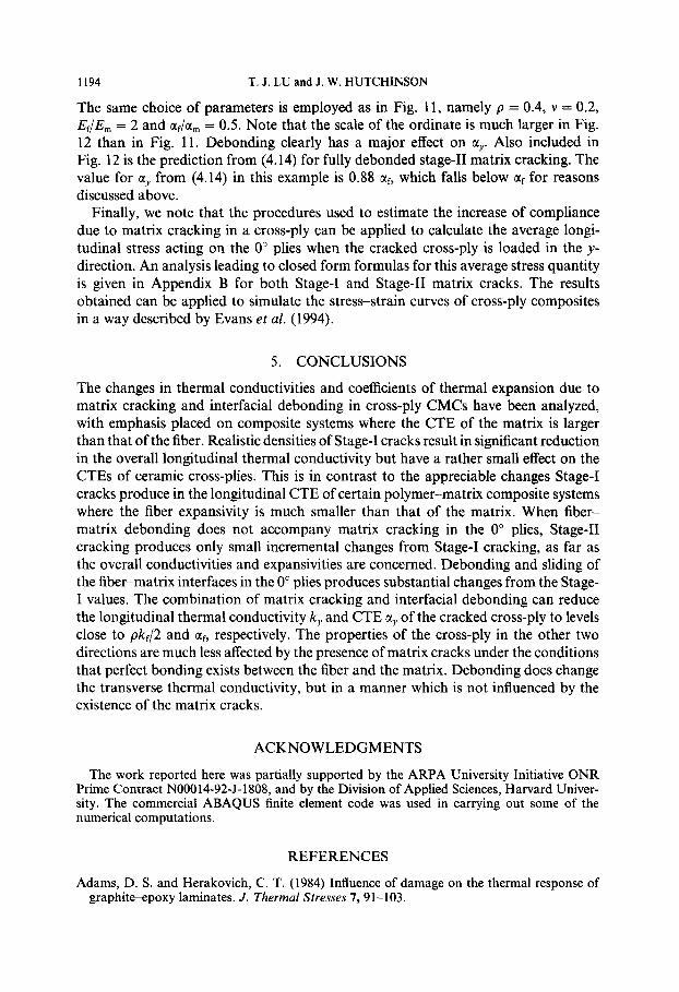
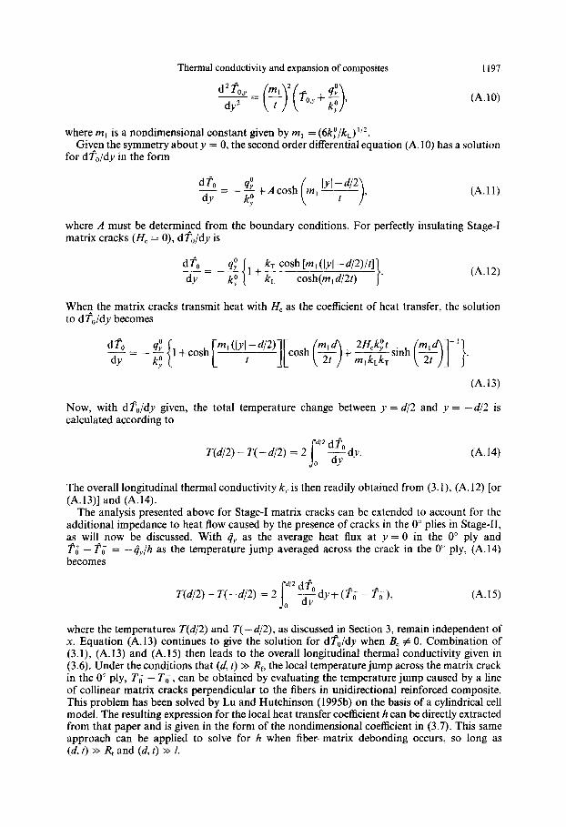
Fig. Al. Effect of fiber-matrix debonding with frictionless sliding on the average longitudinal stress b0 acting on the 0” ply when a cross-ply laminate with stage-11 matrix cracks is loaded by stress d in the same
direction. The constitutive parameters used are RJt = 0.05, p = 0.4, v = 0.2 and &/E,,, = 2.
APPENDIX B : “STRESS CONCENTRATION” IN 0” PLY DUE TO STAGE-I AND STAGE-II MATRIX CRACKS
The solution given in the text for the increase in compliance of a cross-ply due to transverse matrix cracking is employed here to determine the average longitudinal stress 8, sustained by a 0” ply when the cracked cross-ply is loaded by stress d in a direction parallel to the fibers of the 0” ply. Given b0 as a function of crack spacing and moduli variables, one can simulate the tensile stress-strain behaviors of laminated cross-ply composites using the behavior of the unidirectional material in the 0” plies under the assumption that it is the behavior of these plies which dominates (Evans et al., 1994).
If the cross-ply is untracked, b0 = E,@/E:. For the most common CMCs, b0 is only slightly larger than d when no matrix cracks are present. As an illustrative example, one has ho/d = 1 .OS if E,/E,,, = 2, p = 0.4 and q = 1. The “stress concentration factor” bO/b increases markedly, however, once matrix cracking (and interfacial debonding) occurs in the cross-ply and approaches 2 in extreme conditions. For a cross-ply weakened by Stage-I cracks, b0 is rigorously given by
&=bEL 1fC 4 E,; ( ) ’ d ’
(B.1)
where C, has been defined in (4.5). If Stage-II cracks accompanied by debonding and frictionless sliding take place in the cross-ply and if the debond length satisfies the condition 1~ (t, d), 8, is well-approximated by
where D, is given by (4.12). When full debonding with frictionless sliding occurs at the fiber- matrix interface (I= d/2), the dependence of b0 on the crack spacing d is weak. With the Poisson constraining effect exerted by the 90” ply on the deformation of the 0” ply ignored (but not the Poisson interaction between the fiber and matrix in the 0” ply), the load carrying capacity of the cracked cross-ply is due to the 0” plies alone such that b0 = 20. Based on relation (B.2), the ratio 8,/a is depicted in Fig. Al against the crack density parameter t/d as a function of normalized debond length I}& for Rdt = 0.05, EJE, = 2, 4 = 1, p = 0.4 and v = 0.2. It is bounded by so/b = 2 for fully debonding and (B.l) for Stage-I cracks, for which the curve is also displayed in Fig. Al. Observe that although the matrix cracks in the 0” plies have negligible effect on b,,/b when there is perfect bonding between the fiber and matrix, extensive debonding with frictionless sliding have the potential to raise bO/b close to the limit 2.