Embed Size (px)
Citation preview

Thermal Compensation in Stable Recycling Cavity
21/03/2006LSC Meeting 2006
UF LIGO GroupMuzammil A. Arain
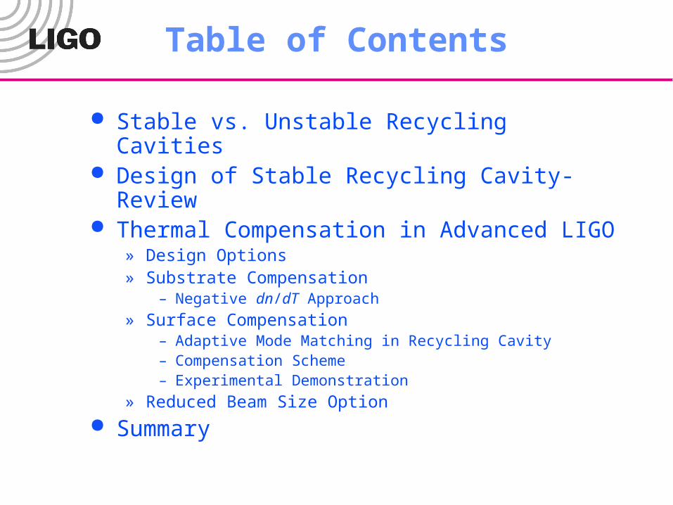
Table of Contents
Stable vs. Unstable Recycling Cavities Design of Stable Recycling Cavity- Review Thermal Compensation in Advanced LIGO
» Design Options» Substrate Compensation
– Negative dn/dT Approach
» Surface Compensation– Adaptive Mode Matching in Recycling Cavity– Compensation Scheme– Experimental Demonstration
» Reduced Beam Size Option
Summary

Advanced LIGO – arm cavities
U00V00W00
Arm Cavities:• Long and stable cavities• Uncertainties due to thermal lensing are probably small, thanks to TCS
TCS focuses on carrier:• Optimize beam size on test masses• Optimize interferometer contrast• Optimize mode matching(?)
U00V00W00
Adv. LIGOMarginally Stable Recycling Cavities
Marginally stable Recycling Cavities:
• All spatial modes of RF-sidebands resonant (current design: mode separation ≈ 4 kHz)• Major loss mechanism for sidebands in TEM00-mode
• Loss of up to 30%-50%• (Also for signal sidebands!)
• Impact on LSC and ASC

U00V00W00
Adv. LIGOStable Recycling Cavities
Stable Recycling Cavities:
• Only fundamental mode of RF-sidebands resonant• Higher order modes suppressed• Strongly reduces losses of TEM00-mode• (Better performance for signal sidebands) • Expect improved LSC, ASC, and even Bull’s eye (mode matching) signals • Interferometer will be much easier to understand and debug

Power Recycling CavityCold State
Parameter Unit Value
MC Waist mm 2.113
MC Waist Loc.-PR1 m 2.0
PR1 ROC m -128.895
PR1 - PR2 m 16.655
PR2 ROC m 1.524
Beam Size @ PR2 mm 3.567
PR2 – PR3 m 16.655
PR3 ROC m 31.384
Beam Size @ PR3 cm 7.23
PR3 –ITM m 24.995
Beam Size @ ITM cm 7.10
ITM ROC m 2037.5
Mode Matching - 1.0
ITMx
PR3
ITMy
PR2
PR1
From MC
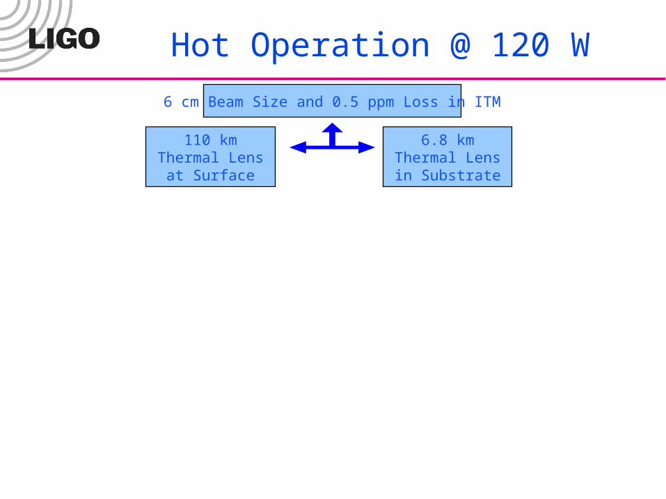
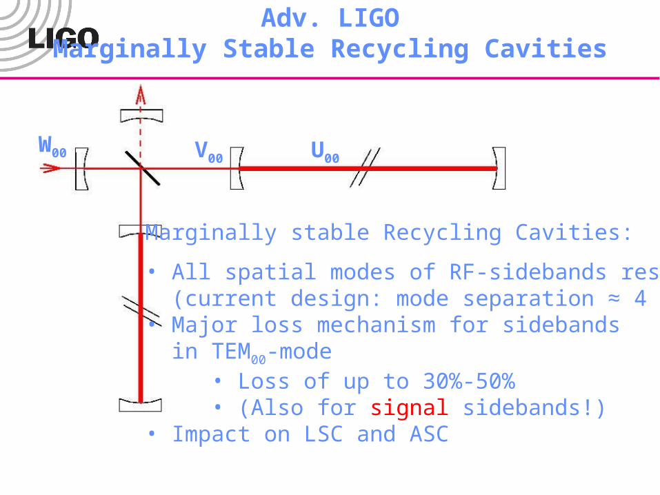
Hot Operation @ 120 W
6 cm Beam Size and 0.5 ppm Loss in ITM
110 km Thermal Lens at Surface
6.8 km Thermal Lens in Substrate
Thermal Lensing in ITM
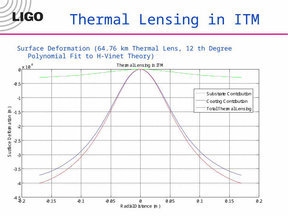
Surface Deformation (64.76 km Thermal Lens, 12 th Degree Polynomial Fit to H-Vinet Theory)
-0.2 -0.15 -0.1 -0.05 0 0.05 0.1 0.15 0.2-4.5
-4
-3.5
-3
-2.5
-2
-1.5
-1
-0.5
0x 10
-8
Radial Distance (m)
Su
rfa
ce D
efo
rma
tion
(m
)
Thermal Lensing in ITM
Substrate Contribution
Coating Contribution
Total Thermal Lensing

Thermal Lensing in Substrate
-0.2 -0.15 -0.1 -0.05 0 0.05 0.1 0.15 0.2-7
-6
-5
-4
-3
-2
-1
0x 10
-7
Radial Distance (m)
The
rmal
Abe
rrat
ions
(m)
Substrate Contribution (23 km)
Coating Contribution (4.93 km)
Total Thermal Lensing (4.09 km)
Thermal Aberrations (12 th Degree Polynomial Fit to H-Vinet Theory)

Optimized Thermal ROC Estimation
x
wo
R(z) R1
s(x)
E1(x,z)E2(x,z)
)(),(
14/1
1
22
),(
12),(
zRi
Azwx
opt
opteAzw
zxE
211
22 )(42
)()(
14/1
2)(
12),( x
xsi
Ri
zRi
zwx
ezw
zxE
optAiR
izR
izw
x
ezw
zxE4
2
)()(
14/1
31
22
)(
12),(
Calculate Overlap Integral b/w E2 and E3 and maximize itw.r.t. the ROC of thermal lens to get the optimal value

The Solution
)(
2
14
)2
(22
22
123
2
)(1
2N
2n
N
2n
2
22
2
22
2
22
2
2
22
2
42
zAAni
AAnAAnAA
zI
opt
n
nn
N
nn
nn
N
nn
nn
N
nn
nn
n
nn
optopt
An analytical solution is difficult however a numerical solution can be obtained. The curve is a parabola like shape and the vertex gives you the optimal value.
2)(for Only Valid xAxs opt
Solution: Numerical Integration
dxeezw
AIxAxsi
zwx opt
)(
12)(
2
12
2 4)(4
)(
22/1

Various Approximations for ITM
-0.2 -0.15 -0.1 -0.05 0 0.05 0.1 0.15 0.2-2.5
-2
-1.5
-1
-0.5
0x 10
-7
Radial Distance (m)
Th
erm
al A
be
rra
tion
(m
)
Data12th Degree Pol. Fit12th Degree Quad8th Degree QuadExact Solution
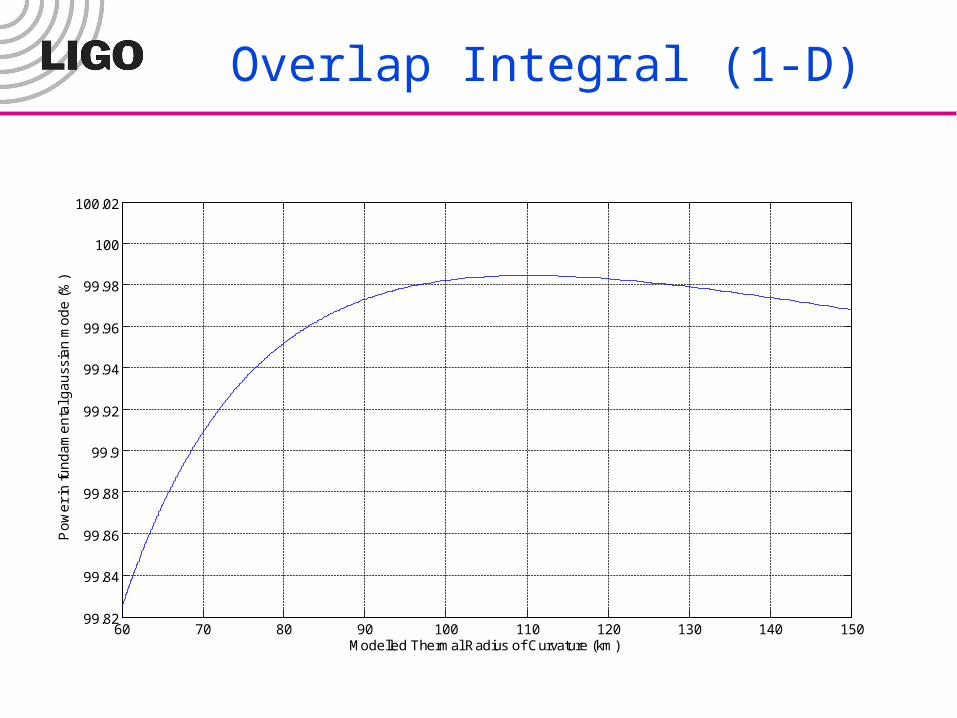
Overlap Integral (1-D)
60 70 80 90 100 110 120 130 140 15099.82
99.84
99.86
99.88
99.9
99.92
99.94
99.96
99.98
100
100.02
Modelled Thermal Radius of Curvature (km)
Po
we
r in
fun
da
me
nta
l ga
uss
ian
mo
de
(%
)

Various Approximations for Substrate
-0.2 -0.15 -0.1 -0.05 0 0.05 0.1 0.15 0.2-4
-3.5
-3
-2.5
-2
-1.5
-1
-0.5
0x 10
-6
Radial Distance (m)
Th
erm
al A
be
rra
tion
(m
)
Ddata
12th Deg. Poly. Fit
12th Deg. Quad
8th Deg. Quad
Exact Spolution

Overlap Integral (1-D)
2 3 4 5 6 7 8 965
70
75
80
85
90
95
100
Modelled Thermal Radius of Curvature (km)
Po
we
r in
fun
da
me
nta
l ga
uss
ian
mo
de
(%
)

Comparison of ROC Change Estimation
Thermal Lens in Substrate
Thermal Lens in ITM
Method Thermal
ROC(Km) Losses
% A2 of 12th Pol. 4.091 37.43 A2 of 8th Pol. 4.890 21.29 Exact Sol. 6.42 10.52
Method
Thermal ROC(Km)
ROCcold (m)
Cold Beam Size (cm)
Losses %
A2 of 12th Pol. 64.768 2012.46 9.29 0.48 A2 of 8th Pol. 77.013 2022.45 8.04 0.23 Exact Sol. 110.10 2038.54 7.05 0.06

Hot Operation @ 120 W
6 cm Beam Size and 0.5 ppm Loss in ITM
110 km Thermal Lens at Surface
6.8 km Thermal Lens in Substrate
Com. Plate
?No
15% Losses in
RC
End?
Yes
Adaptive Mode Matching
No96% Mode Matching
End ?Yes
Ring HeaterOn ITMs
Adaptive TelescopeOn PR2 and PR3
RH & Adaptive Telescope
Option 3Option2Option1
Advantages:1. 100% Mode Match2. No Differential Effects
Disadvantage1. Relatively large power2. Induced Noise
Choose an Option
-ve dn/dt Material Plate
Annular Heatingon Plates
Ring Heating on Plates
Advantages:1. 100% Mode Match2. Insensitive Optics3. Non-power-related
mismatchDisadvantage
1. Only Common Mode Corr
Diff. through RHCommon through PR2 & PR3
Advantages:1. 100% Mode Match2. Low RH Power3. Low Noise Induction
1. Reduce Beam Sizes to 5.5 cm → Higher Noise2. Move Telescope intoarms → Space
Restrictions
Other Options

Compensation Plate for Substrate Compensation

Annular & Ring Heater Compensation
Refractive Index is decreasing at the center
Probe Beam Constant Power
Annular Heating Beam
Plate acts as a diverging lens
Annular Heating
+ve dn/dT Plate(Fused Silica)
Refractive Index is decreasing at the center
Probe Beam Constant Power
Ring HeatersIncreasing Electrical Power
Plate acts as a diverging lens
Ring Heating
+ve dn/dT Plate(Fused Silica)
dT
dn
L
Ln
)1(
Increasing Value

Negative dn/dT CompensationConstant temperature, Uniform refractive index
Probe Beam (1064 nm)Low power
Normal Divergence
Negative dn/DT plate
Probe Beam (1064 nm)Increasing Power
Plate acts as a diverging lens
Plate acts as a simple glass plate
Refractive Index is decreasing at the center
Probe Beam Constant Power
Heating Beam
dT
dn
L
Ln
)1(
Plate acts as a diverging lens
Passive Compensation
Active Compensation
Increasing Value

Active Compensation Requirements:
» CO2 laser system for surface heating
» Availability in Large Size
» Purity/homogeneity
Advantages:» Works without any doubt, trick is use
same beam size as ITM
» Requires very low power (< 2W)
» Highly Efficient/Adaptive
Disadvantages:» New material
» A lot of Data and tests needed
» Requires coating on both surfaces
Option 1: Negative dn/dT
Passive Compensation Requirements:
» Availability in Large Size» Purity/homogeneity» Exact Size absorption values
Advantages:» No laser needed» Highly Efficient» Analogous to compensation in
Faraday Rotator Disadvantages:
» New material» A lot of Data and tests needed» Less Adaptive» Requires coating on both sides
Combination of Two is essential due to substrate heating at 1064 nm
Does such a material Exists ??

Potassium Bromide, Initial Choice
Normally used in IR Spectrometers
Available in large sizes
Crystalline in nature
Soluble in water
Important Properties (KBr): n = 1.5441 @ 1064 nm (dn/dT-(n-1)t = -17.43×10⁻⁶ /0C
Absorption = 0.002 cm-1
Kt = 4.816 W m-1 K-1 @ 319K
Important Properties (Fused Silica): n = 1.4497 @ 1064 nm dn/dT = 8.7×10⁻⁶ /0C t = 5.5 ×10⁻⁷ /0C
Absorption = 2 ×10⁻⁶ cm-1
Kt = 1.37 W m-1 K-1

A Typical Example6.42 km Thermal Lens in Substrate
Crystal Thickness = 2.05 mm Coating Absorption = 2.0 W Uncompensated Losses = 11% After Compensation = 0.001%
-20 -15 -10 -5 0 5 10 15 20-7
-6
-5
-4
-3
-2
-1
0
1x 10
-7
Radial Distance (cm)
Abe
rrat
ions
(m
)
CompensatedUncompensatedCompensation

Other Options for Compensation
Option 2: Ring Heaters General Comments
» Easy to control electrical power» Sensitive to geometry» Requires relatively high power» Compensating a lens of 6.8 km
in substrate might be too much for ring heaters
» Increases the temperature
Further Considerations for Experts
Annular Heating General Comments
» Established technique» Probably will require less power
as compared to Ring Heaters» Silica can be used as
compensation plates» No new material is required» Still needs an extra laser and
related control like negative dn/dT
» Less efficient than negative dn/dT method

Surface Thermal Lensing
1. Highly variable due to coating variations2. Differential Variations can be severe3. Changes the mode in the arm cavity and mode matching can decrease to 96% without correction4. Can cause contrast defects

Adaptive Mode Matching
Ring HeaterOn ITMs
Adaptive TelescopeOn PR2 and PR3
RH & Adaptive Telescope
Advantages:1. 100% Mode Match2. No Differential Effects
Disadvantage1. Relatively large power2. Induced Noise
Advantages:1. 100% Mode Match2. Insensitive Optics3. Non-power-related
mismatchDisadvantage
1. Only Common Mode Corr
Diff. through RHCommon through PR2 & PR3
Advantages:1. 100% Mode Match2. Low RH Power3. Low Noise Induction
Recall:
Procedure1. Use RH on ITMs to keep the ROC on both ITMs same. 2. Use Adaptive correction on PR2 and PR3.
Assumptions1. We have selected a base value of 0.5 ppm as coating
absorption2. Any deviation more than this, has to be corrected by RH.
(Probably requires very low power). 3. If absorption is low, we have to apply some correction in
the hot case.
Proposed Scheme
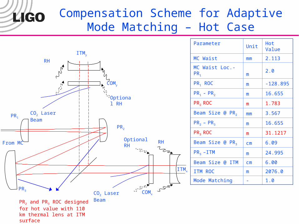
Compensation Scheme for Adaptive Mode Matching – Hot Case
From MC
ITMx
PR3
ITMy
PR2
PR1
COMx
COMy
CO2 Laser Beam
CO2 Laser Beam
Optional RH
Optional RH
RH
RH
Parameter Unit Hot Value
MC Waist mm 2.113
MC Waist Loc.-PR1 m 2.0
PR1 ROC m -128.895
PR1 - PR2 m 16.655
PR2 ROC m 1.783
Beam Size @ PR2 mm 3.567
PR2 – PR3 m 16.655
PR3 ROC m 31.1217
Beam Size @ PR3 cm 6.09
PR3 –ITM m 24.995
Beam Size @ ITM cm 6.00
ITM ROC m 2076.0
Mode Matching - 1.0
PR2 and PR3 ROC designed for hot value with 110 km thermal lens at ITM surface(i.e., 0.5 ppm, ITM ROC 2076 m)

Compensation Scheme for Adaptive Mode Matching- Cold Case
From MC
ITMx
PR3
ITMy
PR2
PR1
COMx
COMy
CO2 Laser Beam
RH
Correction @ PR2 m 10.49
Correction @ PR3 Km 3.72
Beam Size @ PR2 mm 3.567
Beam Size @ PR3 cm 7.10
Parameter Unit Value
MC Waist mm 2.113
MC Waist Loc.-PR3 m 2.0
PR1 ROC m -128.895
PR1 - PR2 m 16.655
PR2 ROC m 1.524
Beam Size @ PR2 mm 3.567
PR2 – PR3 m 16.655
PR3 ROC m 31.384
Beam Size @ PR3 cm 7.23
PR3 –ITM m 24.995
Beam Size @ ITM cm 7.10
ITM ROC m 2037.5
Mode Matching - 1.0

Plate Heating
Details of Adaptive CorrectionPR Cavity Designed for Hot Case
Correction @ PR2
» Requires a 10 m converging lens at 3.5 mm as we move from hot to cold case
» Easily achievable by using CO2 heating
» Experimental demonstration in progress
Correction @ PR3
» Requires a 3.4 km diverging lens at 7.1 cm beam size as we move from cold to hot case
» Proposed locations are substrate of PR3 or separate plate before beam splitter
» No higher order losses in the hot state
» 10% higher order losses in the cold state
» Cold state losses can be decreased by using CO2 beam of larger size
Substrate Lens Heating
BS

Experimental Demonstration
0.85
0.9
0.95
1
Bac
k F
ocal
Dis
tanc
e (m
)
0 0.5 1 1.5 2 2.5 3 3.50
10
20
30
40
50
60
Heating Beam Power (W)
The
rmal
Len
s F
ocal
Len
gth
(m)
1 cm Thick Fused Silica Plate
HR
Coa
ting
@
1 m
icro
n 1 cm CO2 Heating Beam
1.8 mm Probe Beam
Summary Solid Line is H-V Theory Dots are experimental data 10 m focal length lens at 1.2 W of
surface heating at 1.8 mm probe beam and 1.0 cm heating beam
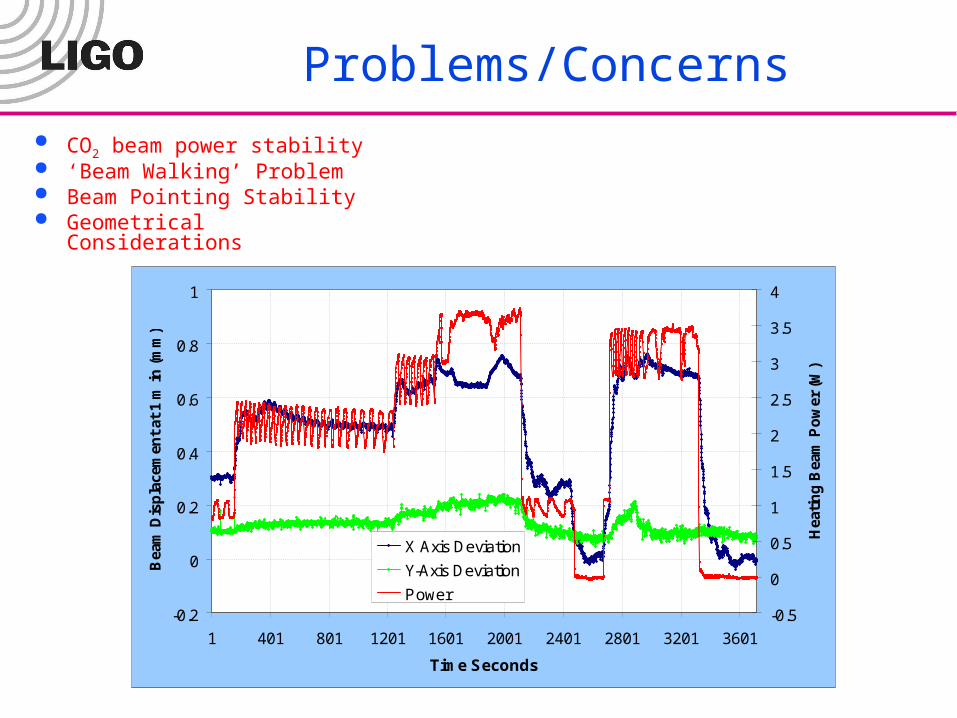
Problems/Concerns
CO2 beam power stability ‘Beam Walking’ Problem Beam Pointing Stability Geometrical Considerations
-0.2
0
0.2
0.4
0.6
0.8
1
1 401 801 1201 1601 2001 2401 2801 3201 3601
Time Seconds
Bea
m D
isp
lace
men
t at
1 m
in (
mm
)
-0.5
0
0.5
1
1.5
2
2.5
3
3.5
4
Hea
tin
g B
eam
Po
wer
(W
)
X Axis Deviation
Y-Axis Deviation
Power

Inherently ‘Athermal’ Cavity
Reduce the Beam Size
Increase the ROC

Reduced beam Size Operation
4
6
8
10
12
14
16
18
20
2000.0 2020.0 2040.0 2060.0 2080.0 2100.0 2120.0 2140.0 2160.0 2180.0 2200.0
ROC (m)
wE
TM
=
wE
TM
(c
m)
-1.000
-0.975
-0.950
-0.925
-0.900
-0.875
-0.850
-0.825
-0.800
g F
ac
tor
Beam Radius
g factor
(2076, 6.0, -0.929)120 W Mode
No Correction Required Thermally Stable No differential problems
Increased Noise Reduces Sensitivity Deviates from 6.0 cm magical beam
size value ??
Can we operate here ???

Thermally Insensitive Operation at Reduced Beam Size
2050 2075 2100 2125 2150 2175 2200 2225 22500.92
0.93
0.94
0.95
0.96
0.97
0.98
0.99
1
Hot ROC of ITM (m)
Mo
de
Mis
ma
tch
fro
m C
old
to H
ot C
on
diti
on
4.5
5
5.5
6
6.5
7
7.5
8
8.5
Bea
m S
ize
in b
oth
Col
d an
d H
ot C
ondi
tions
(cm
)
X: 2137Y: 5.691
Hot ROC = 2137 m, Cold ROC = 2096.27m Beam Size = 5.7 cm No Correction Required More Stable
Arbitrary Limit of 99% Mode Matching
Thermal Noise Considerations
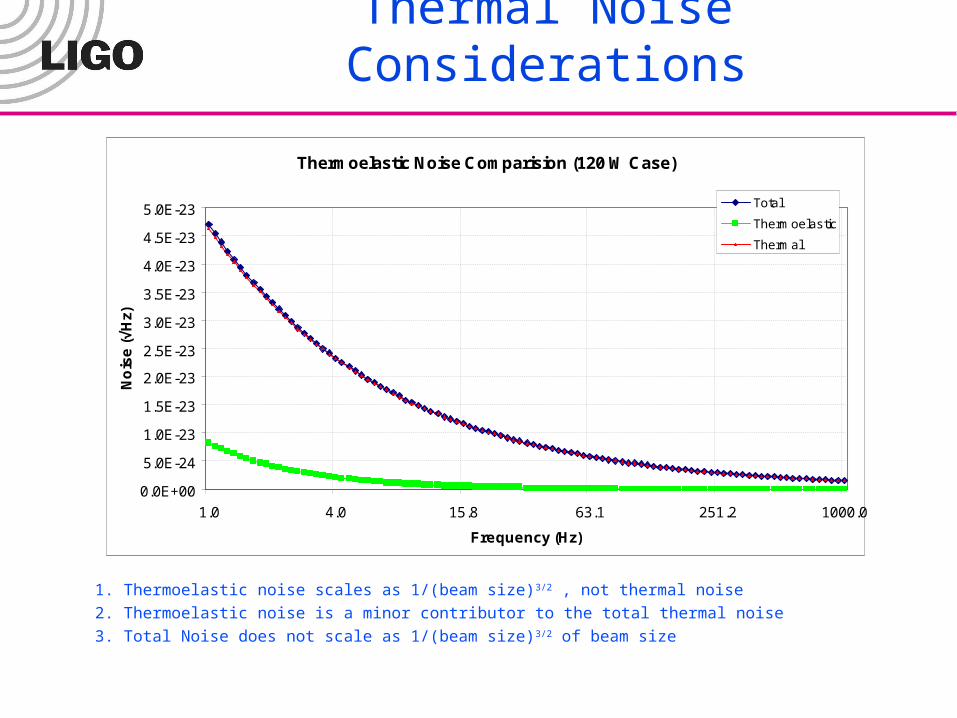
Thermoelastic Noise Comparision (120 W Case)
0.0E+00
5.0E-24
1.0E-23
1.5E-23
2.0E-23
2.5E-23
3.0E-23
3.5E-23
4.0E-23
4.5E-23
5.0E-23
1.0 4.0 15.8 63.1 251.2 1000.0
Frequency (Hz)
No
ise
(√
Hz)
Total
Thermoelastic
Thermal
1. Thermoelastic noise scales as 1/(beam size)3/2 , not thermal noise
2. Thermoelastic noise is a minor contributor to the total thermal noise
3. Total Noise does not scale as 1/(beam size)3/2 of beam size

Comparison of Thermoelastic Noise
Thermoelastic Noise Comparision (120W Case)
0.0E+00
1.0E-23
2.0E-23
3.0E-23
4.0E-23
5.0E-23
6.0E-23
1.0 4.0 15.8 63.1 251.2 1000.0
Frequency (Hz)
No
ise
(√
Hz)
1.0362
1.0364
1.0366
1.0368
1.0370
1.0372
1.0374
1.0376
1.0378
1.0380
5.7 cm
6.0 cm
N5.69/N6.0

Comparison of Total Noise
Total Noise Comparision (120W Case)
0.0E+00
2.0E-24
4.0E-24
6.0E-24
8.0E-24
1.0E-23
1.2E-23
1.4E-23
1.6E-23
1.8E-23
2.0E-23
1.0 4.0 15.8 63.1 251.2 1000.0
Frequency (Hz)
No
ise
(√
Hz)
0.970
0.980
0.990
1.000
1.010
1.020
1.030
1.040
1.050
Total Noise at 6 cm
Total Noise at 5.7 cm
Ratio
Maximum hit of 4.5 % at 64 Hz
Is it acceptable??

Familiar Bench Noise Curve
5.7 cm Beam Size Details: Finesse: 1238.07 Power Recycling Factor: 16.83 Power on beam splitter: 2019.75 NS Binary Inspiral range: 126.24 Mpc Stochastic signal sensitivity: 6.836e-
009/h^2
6.0 cm Beam Size Details: Finesse: 1238.07 Power Recycling Factor: 16.83 Power on beam splitter: 2019.75 NS Binary Inspiral range: 130.61 Mpc Stochastic signal sensitivity: 6.682e-
009/h^2
Hardly any difference in Log Scale
Can we sacrifice a little sensitivity ??
100
101
102
103
10-25
10-24
10-23
10-22
10-21
10-20
10-19
f / Hz
h(f)
/ H
z1/2
quant.Int. thermalSusp. thermalResidual GasTotal noise

Summary/Recommendations
6 cm Beam Size and 0.5 ppm Loss in ITM
110 km Thermal Lens at Surface
6.8 km Thermal Lens in Substrate
Com. Plate
?
Yes
Adaptive Mode Matching
RH & Adaptive Telescope
Option 3
Diff. through RHCommon through PR2 & PR3
Advantages:1. 100% Mode Match2. Low RH Power3. Low Noise Induction
1. Reduce Beam Sizes to 5.7 cm → Higher Noise
-ve dn/dt Material Plate
RecommendationSuggestionsComments