Embed Size (px)
Citation preview
97
Chapter 5
Thermal cameras
Thermal network cameras create images based on the principles of infrared (IR) radiation. All objects and organisms generate some amount of heat. Heat is a form of light that is invisible to the eye and is also known as thermal IR radiation. The thermal camera serves as a heat sensor that detects temperature diffe ences between objects and the scene itself. Rather than a picture of light, the thermal image is a visual capture of heat. The more heat an object emits, the brighter it appears in a thermal image.
Thermal images give the most information when there are significant temperature diffe ences in a scene. Images are generally produced in grayscale where dark areas indicate colder temperatures and light areas warmer ones. Color palettes can be added to enhance diffe ent shades in the image.
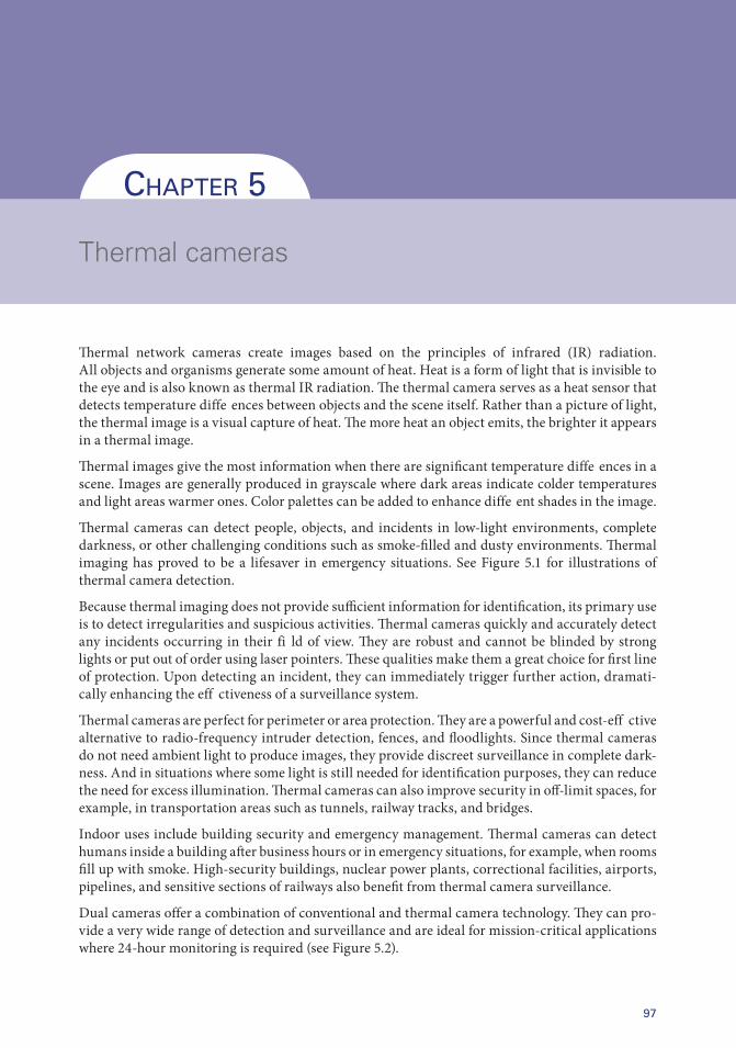
Thermal cameras can detect people, objects, and incidents in low-light environments, complete darkness, or other challenging conditions such as smoke-filled and dusty environments. Thermal imaging has proved to be a lifesaver in emergency situations. See Figure 5.1 for illustrations of thermal camera detection.
Because thermal imaging does not provide sufficient information for identification, its primary use is to detect irregularities and suspicious activities. Thermal cameras quickly and accurately detect any incidents occurring in their fi ld of view. They are robust and cannot be blinded by strong lights or put out of order using laser pointers. These qualities make them a great choice for first line of protection. Upon detecting an incident, they can immediately trigger further action, dramati-cally enhancing the eff ctiveness of a surveillance system.
Thermal cameras are perfect for perimeter or area protection. They are a powerful and cost- eff ctive alternative to radio-frequency intruder detection, fences, and floodlights. Since thermal cameras do not need ambient light to produce images, they provide discreet surveillance in complete dark-ness. And in situations where some light is still needed for identification purposes, they can reduce the need for excess illumination. Thermal cameras can also improve security in off-limit spaces, for example, in transportation areas such as tunnels, railway tracks, and bridges.
Indoor uses include building security and emergency management. Thermal cameras can detect humans inside a building after business hours or in emergency situations, for example, when rooms fill up with smoke. High-security buildings, nuclear power plants, correctional facilities, airports, pipelines, and sensitive sections of railways also benefit from thermal camera surveillance.
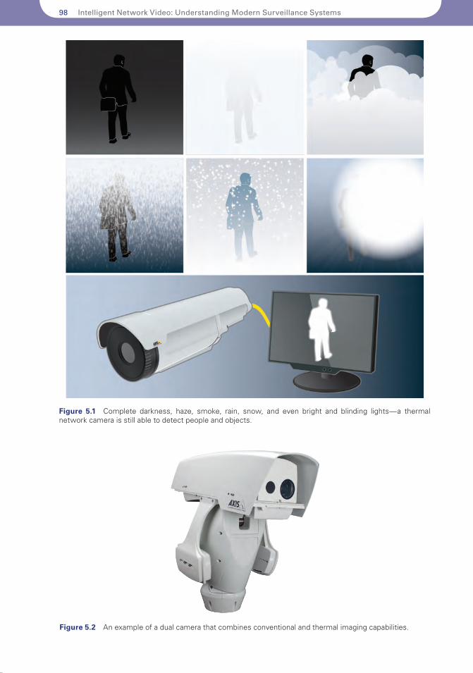
Dual cameras offer a combination of conventional and thermal camera technology. They can pro-vide a very wide range of detection and surveillance and are ideal for mission-critical applications where 24-hour monitoring is required (see Figure 5.2).
98 Intelligent Network Video: Understanding Modern Surveillance Systems
Figure 5.1 Complete darkness, haze, smoke, rain, snow, and even bright and blinding lights—a thermal network camera is still able to detect people and objects.
Figure 5.2 An example of a dual camera that combines conventional and thermal imaging capabilities.
Thermal cameras 99
Thermal imaging technology is not new. But until recently, costs were prohibitive. This made practical applications outside the military, law enforcement, and high-security locations rare. The change is a result of new sensors. Streamlining sensor production and lens material improvements are driving volumes and making prices more reasonable. Today, thermal imag-ing is applied in various lines of business, such as the aircraft industry, shipping industry, and other critical infrastructure. The technology is also used in public services like firefighting and law enforcement. Lately, it has even appeared in consumer products, such as mobile devices and luxury cars.
This chapter gives an overview of the basic principles of thermal imaging, along with an overview of the components in a thermal camera. Calculation of detection range, integration with intelligent video analytics, and export regulations are other topics covered here.
5.1 HOW THERMAL IMAGING WORKS
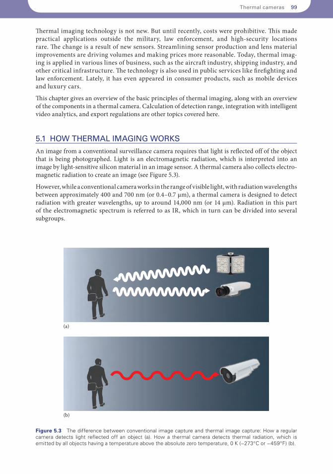
An image from a conventional surveillance camera requires that light is reflected off of the object that is being photographed. Light is an electromagnetic radiation, which is interpreted into an image by light-sensitive silicon material in an image sensor. A thermal camera also collects electro-magnetic radiation to create an image (see Figure 5.3).
However, while a conventional camera works in the range of visible light, with radiation wavelengths between approximately 400 and 700 nm (or 0.4–0.7 µm), a thermal camera is designed to detect radiation with greater wavelengths, up to around 14,000 nm (or 14 µm). Radiation in this part of the electromagnetic spectrum is referred to as IR, which in turn can be divided into several subgroups.
(a)
(b)
Figure 5.3 The difference between conventional image capture and thermal image capture: How a regular camera detects light reflected off an object (a). How a thermal camera detects thermal radiation, which is emitted by all objects having a temperature above the absolute zero temperature, 0 K (−273°C or −459°F) (b).
100 Intelligent Network Video: Understanding Modern Surveillance Systems
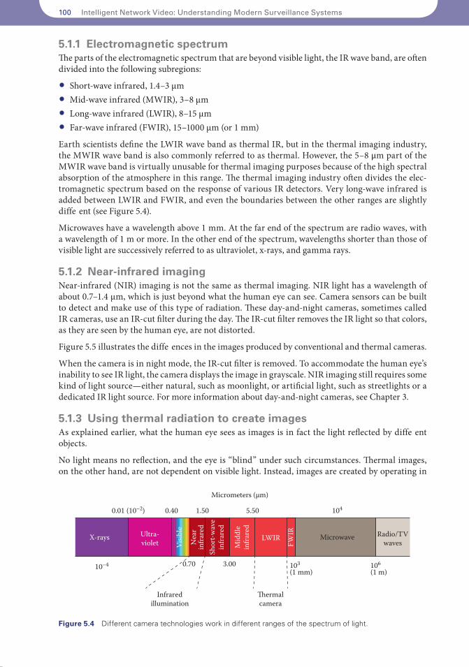
5.1.1 Electromagnetic spectrumThe parts of the electromagnetic spectrum that are beyond visible light, the IR wave band, are often divided into the following subregions:
• Short-wave infrared, 1.4–3 µm• Mid-wave infrared (MWIR), 3–8 µm• Long-wave infrared (LWIR), 8–15 µm• Far-wave infrared (FWIR), 15–1000 µm (or 1 mm)
Earth scientists define the LWIR wave band as thermal IR, but in the thermal imaging industry, the MWIR wave band is also commonly referred to as thermal. However, the 5–8 μm part of the MWIR wave band is virtually unusable for thermal imaging purposes because of the high spectral absorption of the atmosphere in this range. The thermal imaging industry often divides the elec-tromagnetic spectrum based on the response of various IR detectors. Very long-wave infrared is added between LWIR and FWIR, and even the boundaries between the other ranges are slightly diffe ent (see Figure 5.4).
Microwaves have a wavelength above 1 mm. At the far end of the spectrum are radio waves, with a wavelength of 1 m or more. In the other end of the spectrum, wavelengths shorter than those of visible light are successively referred to as ultraviolet, x-rays, and gamma rays.
5.1.2 Near-infrared imagingNear-infrared (NIR) imaging is not the same as thermal imaging. NIR light has a wavelength of about 0.7–1.4 µm, which is just beyond what the human eye can see. Camera sensors can be built to detect and make use of this type of radiation. These day-and-night cameras, sometimes called IR cameras, use an IR-cut filter during the day. The IR-cut filter removes the IR light so that colors, as they are seen by the human eye, are not distorted.
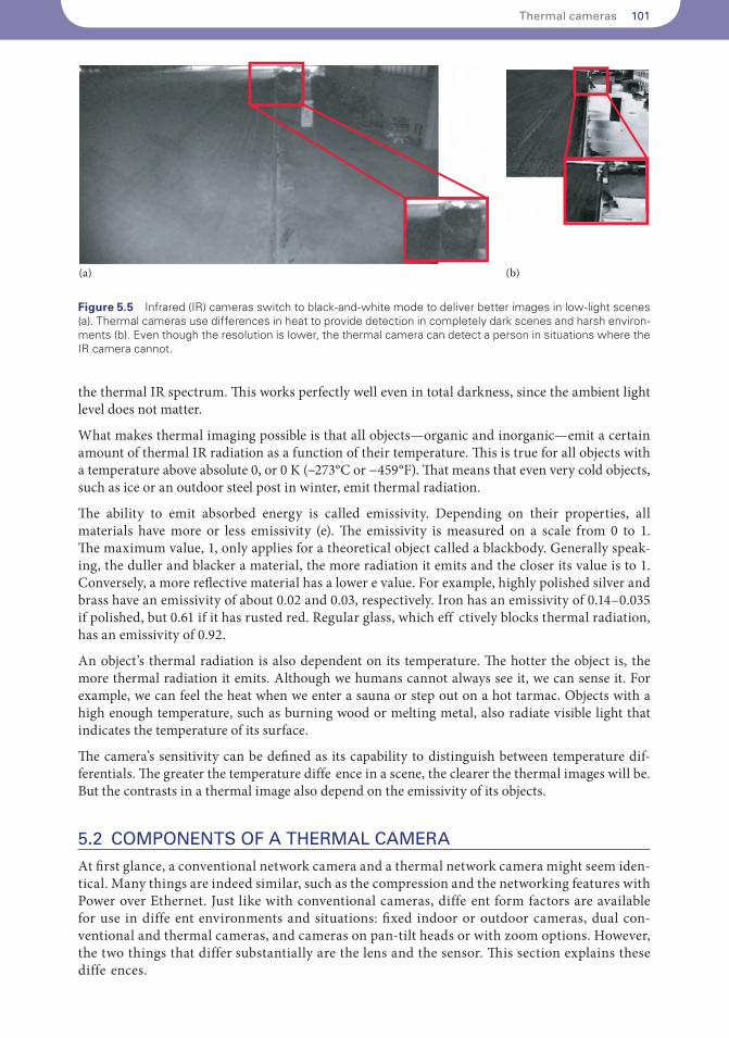
Figure 5.5 illustrates the diffe ences in the images produced by conventional and thermal cameras.
When the camera is in night mode, the IR-cut filter is removed. To accommodate the human eye’s inability to see IR light, the camera displays the image in grayscale. NIR imaging still requires some kind of light source—either natural, such as moonlight, or artificial light, such as streetlights or a dedicated IR light source. For more information about day-and-night cameras, see Chapter 3.
5.1.3 Using thermal radiation to create imagesAs explained earlier, what the human eye sees as images is in fact the light reflected by diffe ent objects.
No light means no reflection, and the eye is “blind” under such circumstances. Thermal images, on the other hand, are not dependent on visible light. Instead, images are created by operating in
X-rays Ultra-violet N
ear
infra
red
Visib
le
Mid
dle
infra
red
LWIR Radio/TVwaves
Microwave
Shor
t-wav
ein
frare
d
10–4 103(1 mm)
104
106(1 m)
0.40
0.70
1.50
3.00
Micrometers (µm)
5.500.01 (10–2)
Infraredillumination
�ermalcamera
FWIR
Figure 5.4 Different camera technologies work in different ranges of the spectrum of light.
Thermal cameras 101
the thermal IR spectrum. This works perfectly well even in total darkness, since the ambient light level does not matter.
What makes thermal imaging possible is that all objects—organic and inorganic—emit a certain amount of thermal IR radiation as a function of their temperature. This is true for all objects with a temperature above absolute 0, or 0 K (−273°C or −459°F). That means that even very cold objects, such as ice or an outdoor steel post in winter, emit thermal radiation.
The ability to emit absorbed energy is called emissivity. Depending on their properties, all materials have more or less emissivity (e). The emissivity is measured on a scale from 0 to 1. The maximum value, 1, only applies for a theoretical object called a blackbody. Generally speak-ing, the duller and blacker a material, the more radiation it emits and the closer its value is to 1. Conversely, a more reflective material has a lower e value. For example, highly polished silver and brass have an emissivity of about 0.02 and 0.03, respectively. Iron has an emissivity of 0.14–0.035 if polished, but 0.61 if it has rusted red. Regular glass, which eff ctively blocks thermal radiation, has an emissivity of 0.92.
An object’s thermal radiation is also dependent on its temperature. The hotter the object is, the more thermal radiation it emits. Although we humans cannot always see it, we can sense it. For example, we can feel the heat when we enter a sauna or step out on a hot tarmac. Objects with a high enough temperature, such as burning wood or melting metal, also radiate visible light that indicates the temperature of its surface.
The camera’s sensitivity can be defined as its capability to distinguish between temperature dif-ferentials. The greater the temperature diffe ence in a scene, the clearer the thermal images will be. But the contrasts in a thermal image also depend on the emissivity of its objects.
5.2 COMPONENTS OF A THERMAL CAMERA
At first glance, a conventional network camera and a thermal network camera might seem iden-tical. Many things are indeed similar, such as the compression and the networking features with Power over Ethernet. Just like with conventional cameras, diffe ent form factors are available for use in diffe ent environments and situations: fixed indoor or outdoor cameras, dual con-ventional and thermal cameras, and cameras on pan-tilt heads or with zoom options. However, the two things that differ substantially are the lens and the sensor. This section explains these diffe ences.
(a) (b)
Figure 5.5 Infrared (IR) cameras switch to black-and-white mode to deliver better images in low-light scenes (a). Thermal cameras use differences in heat to provide detection in completely dark scenes and harsh environ-ments (b). Even though the resolution is lower, the thermal camera can detect a person in situations where the IR camera cannot.
102 Intelligent Network Video: Understanding Modern Surveillance Systems
5.2.1 SensorsThe sensor in a thermal camera is an array of thousands of detectors that are sensitive to thermal IR radiation. The sensor detects, records, and then converts the thermal IR information into electrical signals. This is what makes the video image. Detectors used for thermal imaging can be broadly divided into two types: cooled and uncooled IR sensors.
Uncooled IR image sensors are smaller and built with fewer moving parts, which makes them less expensive than their cooled counterparts. Unlike cameras with uncooled sensors, cameras with cooled sensors generally need to be serviced, although newer designs based on Sterling Motors need less service. Also, the cooling medium must be refilled every 8,000–10,000 hours.
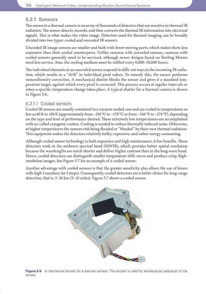
The individual elements in an uncooled sensor respond in diffe ent ways to the incoming IR radia-tion, which results in a “drift” in individual pixel values. To remedy this, the sensor performs nonuniformity correction. A mechanical shutter blocks the sensor and gives it a standard tem-perature target, against which every pixel is corrected. This process occurs at regular intervals or when a specific temperature change takes place. A typical shutter for a thermal camera is shown in Figure 5.6.
5.2.1.1 Cooled sensorsCooled IR sensors are usually contained in a vacuum-sealed case and are cooled to temperatures as low as 60 K to 100 K (approximately from −210 °C to −170 °C or from −346 °F to −274 °F), depending on the type and level of performance desired. These extremely low temperatures are accomplished with so-called cryogenic coolers. Cooling is needed to reduce thermally induced noise. Otherwise, at higher temperatures the sensors risk being flooded or “blinded” by their own thermal radiation. This equipment makes the detectors relatively bulky, expensive, and rather energy consuming.
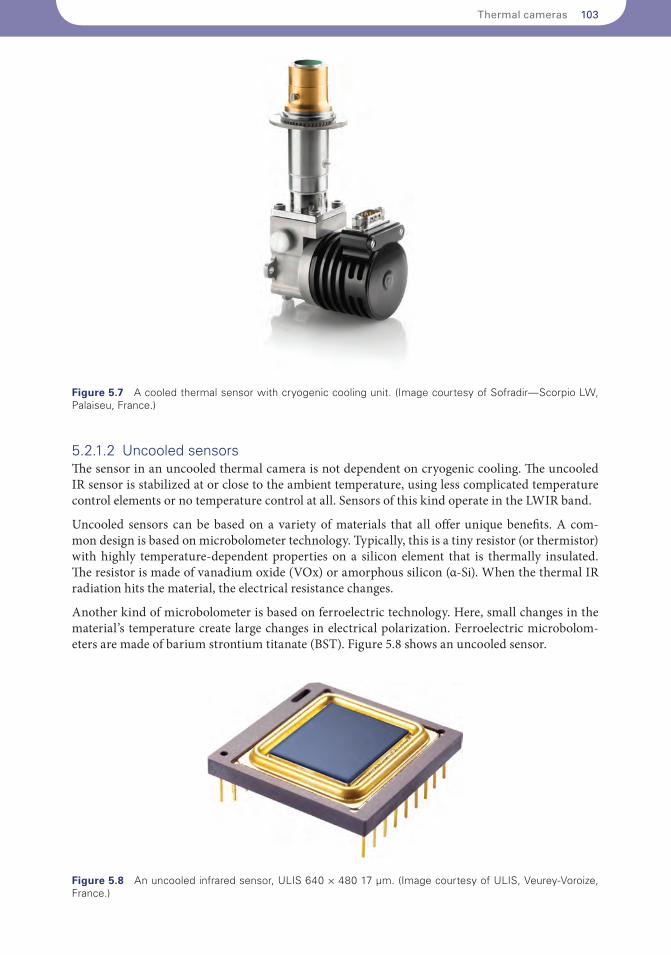
Although cooled sensor technology is both expensive and high maintenance, it has benefits. These detectors work in the midwave spectral band (MWIR), which provides better spatial resolution because the wavelengths are much shorter and deliver higher contrast than in the long-wave band. Hence, cooled detectors can distinguish smaller temperature diffe ences and produce crisp, high-resolution images. See Figure 5.7 for an example of a cooled sensor.
Another advantage with cooled sensors is that the greater sensitivity also allows the use of lenses with high f-numbers (or f-stops). Consequently, cooled detectors are a better choice for long-range detection, that is, 5–16 km (3–10 miles). Figure 5.7 shows a cooled sensor.
Figure 5.6 A mechanical shutter for a thermal camera. The shutter is used for temperature calibration of the sensor.
Thermal cameras 103
5.2.1.2 Uncooled sensorsThe sensor in an uncooled thermal camera is not dependent on cryogenic cooling. The uncooled IR sensor is stabilized at or close to the ambient temperature, using less complicated temperature control elements or no temperature control at all. Sensors of this kind operate in the LWIR band.
Uncooled sensors can be based on a variety of materials that all offer unique benefits. A com-mon design is based on microbolometer technology. Typically, this is a tiny resistor (or thermistor) with highly temperature-dependent properties on a silicon element that is thermally insulated. The resistor is made of vanadium oxide (VOx) or amorphous silicon (α-Si). When the thermal IR radiation hits the material, the electrical resistance changes.
Another kind of microbolometer is based on ferroelectric technology. Here, small changes in the material’s temperature create large changes in electrical polarization. Ferroelectric microbolom-eters are made of barium strontium titanate (BST). Figure 5.8 shows an uncooled sensor.
Figure 5.7 A cooled thermal sensor with cryogenic cooling unit. (Image courtesy of Sofradir—Scorpio LW, Palaiseu, France.)
Figure 5.8 An uncooled infrared sensor, ULIS 640 × 480 17 µm. (Image courtesy of ULIS, Veurey-Voroize, France.)
104 Intelligent Network Video: Understanding Modern Surveillance Systems
Changes in scene temperature cause changes in the bolometer, which are then converted into electri-cal signals and processed into an image. The camera’s sensitivity to thermal radiation, which deter-mines its ability to distinguish diffe ent temperature diffe ences in a scene, can be expressed as its noise equivalent temperature diffe ence (NETD) value. Most thermal network cameras have an NETD value of 50–100 mK, though there are newer generations of bolometers that have an NETD as low as 20 mK.
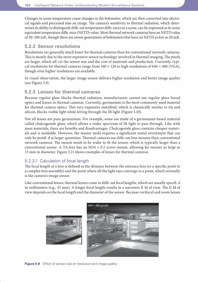
5.2.2 Sensor resolutionsResolutions are generally much lower for thermal cameras than for conventional network cameras. This is mostly due to the more expensive sensor technology involved in thermal imaging. The pixels are larger, which aff cts the sensor size and the cost of materials and production. Currently, typi-cal resolutions for thermal cameras range from 160 × 128 to high resolutions of 640 × 480 (VGA), though even higher resolutions are available.
In visual observation, the larger image sensor delivers higher resolution and better image quality (see Figure 5.9).
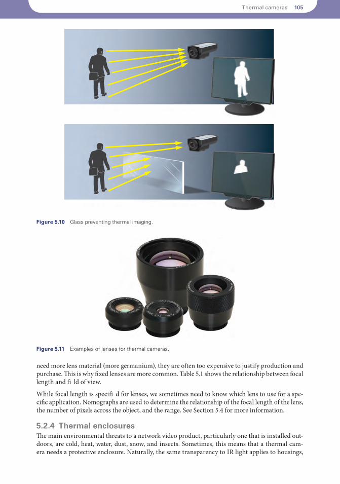
5.2.3 Lenses for thermal camerasBecause regular glass blocks thermal radiation, manufacturers cannot use regular glass–based optics and lenses in thermal cameras. Currently, germanium is the most commonly used material for thermal camera optics. This very expensive metalloid, which is chemically similar to tin and silicon, blocks visible light while letting through the IR light (Figure 5.10).
Not all lenses are pure germanium. For example, some are made of a germanium-based material called chalcogenide glass, which allows a wider spectrum of IR light to pass through. Like with most materials, there are benefits and disadvantages. Chalcogenide glass contains cheaper materi-als and is moldable. However, the master mold requires a significant initial investment that can only be justifi d at larger quantities. Thermal cameras use diffe ent lens mounts than conventional network cameras. The mount needs to be wider to fit the sensor, which is typically larger than a conventional sensor. A TA-lens has an M34 × 0.5 screw mount, allowing for sensors as large as 13 mm in diameter. Figure 5.11 shows examples of lenses for thermal cameras.
5.2.3.1 Calculation of focal lengthThe focal length of a lens is defined as the distance between the entrance lens (or a specific point in a complex lens assembly) and the point where all the light rays converge to a point, which normally is the camera’s image sensor.
Like conventional lenses, thermal lenses come in diffe ent focal lengths, which are usually specifi d in millimeters (e.g., 35 mm). A longer focal length results in a narrower fi ld of view. The fi ld of view depends on the focal length and the diameter of the sensor. Because varifocal and zoom lenses
160 × 128 pixels
640 × 480 pixels
Figure 5.9 Effect of sensor size on resolution and image quality.
Thermal cameras 105
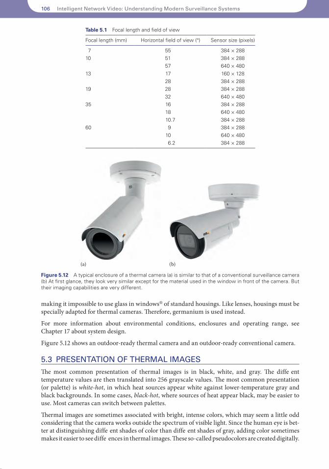
need more lens material (more germanium), they are often too expensive to justify production and purchase. This is why fixed lenses are more common. Table 5.1 shows the relationship between focal length and fi ld of view.
While focal length is specifi d for lenses, we sometimes need to know which lens to use for a spe-cific application. Nomographs are used to determine the relationship of the focal length of the lens, the number of pixels across the object, and the range. See Section 5.4 for more information.
5.2.4 Thermal enclosuresThe main environmental threats to a network video product, particularly one that is installed out-doors, are cold, heat, water, dust, snow, and insects. Sometimes, this means that a thermal cam-era needs a protective enclosure. Naturally, the same transparency to IR light applies to housings,
Figure 5.10 Glass preventing thermal imaging.
Figure 5.11 Examples of lenses for thermal cameras.
106 Intelligent Network Video: Understanding Modern Surveillance Systems
making it impossible to use glass in windows® of standard housings. Like lenses, housings must be specially adapted for thermal cameras. Therefore, germanium is used instead.
For more information about environmental conditions, enclosures and operating range, see Chapter 17 about system design.
Figure 5.12 shows an outdoor-ready thermal camera and an outdoor-ready conventional camera.
5.3 PRESENTATION OF THERMAL IMAGES
The most common presentation of thermal images is in black, white, and gray. The diffe ent temperature values are then translated into 256 grayscale values. The most common presentation (or palette) is white-hot, in which heat sources appear white against lower-temperature gray and black backgrounds. In some cases, black-hot, where sources of heat appear black, may be easier to use. Most cameras can switch between palettes.
Thermal images are sometimes associated with bright, intense colors, which may seem a little odd considering that the camera works outside the spectrum of visible light. Since the human eye is bet-ter at distinguishing diffe ent shades of color than diffe ent shades of gray, adding color sometimes makes it easier to see diffe ences in thermal images. These so-called pseudocolors are created digitally.
Table 5.1 Focal length and field of view
Focal length (mm) Horizontal field of view (°) Sensor size (pixels)
7 55 384 × 28810 51 384 × 288
57 640 × 48013 17 160 × 128
28 384 × 28819 28 384 × 288
32 640 × 48035 16 384 × 288
18 640 × 48010.7 384 × 288
60 9 384 × 28810 640 × 4806.2 384 × 288
(a) (b)
Figure 5.12 A typical enclosure of a thermal camera (a) is similar to that of a conventional surveillance camera (b) At first glance, they look very similar except for the material used in the window in front of the camera. But their imaging capabilities are very different.
Thermal cameras 107
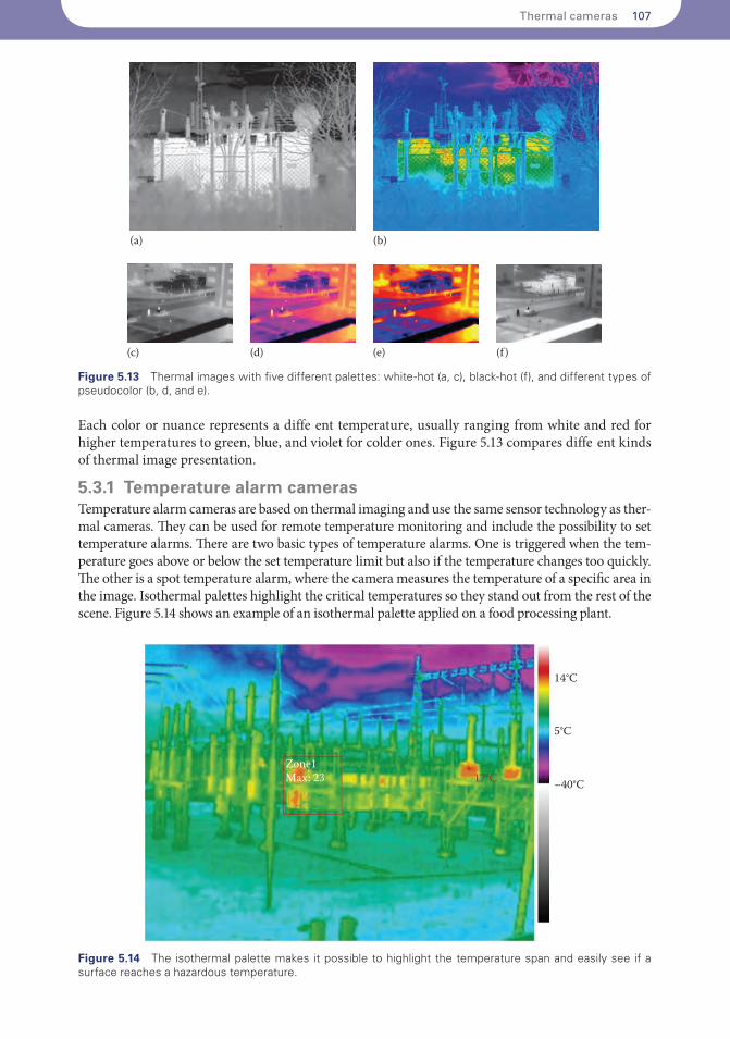
Each color or nuance represents a diffe ent temperature, usually ranging from white and red for higher temperatures to green, blue, and violet for colder ones. Figure 5.13 compares diffe ent kinds of thermal image presentation.
5.3.1 Temperature alarm camerasTemperature alarm cameras are based on thermal imaging and use the same sensor technology as ther-mal cameras. They can be used for remote temperature monitoring and include the possibility to set temperature alarms. There are two basic types of temperature alarms. One is triggered when the tem-perature goes above or below the set temperature limit but also if the temperature changes too quickly. The other is a spot temperature alarm, where the camera measures the temperature of a specific area in the image. Isothermal palettes highlight the critical temperatures so they stand out from the rest of the scene. Figure 5.14 shows an example of an isothermal palette applied on a food processing plant.
(a) (b)
(c) (d) (e) (f )
Figure 5.13 Thermal images with five different palettes: white-hot (a, c), black-hot (f), and different types of pseudocolor (b, d, and e).
14°C
5°C
–40°C
Zone1Max: 23 17°C
+
Figure 5.14 The isothermal palette makes it possible to highlight the temperature span and easily see if a surface reaches a hazardous temperature.
108 Intelligent Network Video: Understanding Modern Surveillance Systems
5.4 DETERMINING DETECTION RANGE
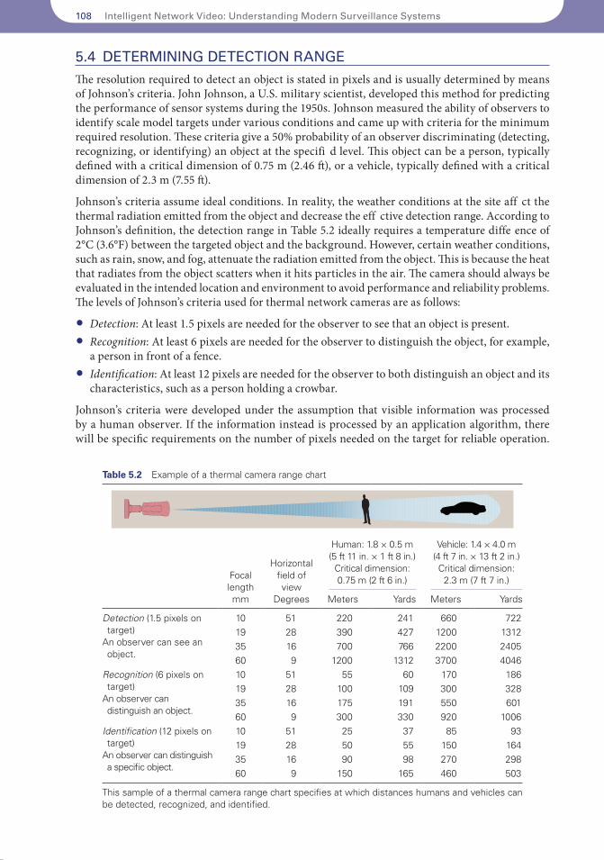
The resolution required to detect an object is stated in pixels and is usually determined by means of Johnson’s criteria. John Johnson, a U.S. military scientist, developed this method for predicting the performance of sensor systems during the 1950s. Johnson measured the ability of observers to identify scale model targets under various conditions and came up with criteria for the minimum required resolution. These criteria give a 50% probability of an observer discriminating (detecting, recognizing, or identifying) an object at the specifi d level. This object can be a person, typically defined with a critical dimension of 0.75 m (2.46 ft), or a vehicle, typically defined with a critical dimension of 2.3 m (7.55 ft).
Johnson’s criteria assume ideal conditions. In reality, the weather conditions at the site aff ct the thermal radiation emitted from the object and decrease the eff ctive detection range. According to Johnson’s definition, the detection range in Table 5.2 ideally requires a temperature diffe ence of 2°C (3.6°F) between the targeted object and the background. However, certain weather conditions, such as rain, snow, and fog, attenuate the radiation emitted from the object. This is because the heat that radiates from the object scatters when it hits particles in the air. The camera should always be evaluated in the intended location and environment to avoid performance and reliability problems. The levels of Johnson’s criteria used for thermal network cameras are as follows:
• Detection: At least 1.5 pixels are needed for the observer to see that an object is present.• Recognition: At least 6 pixels are needed for the observer to distinguish the object, for example,
a person in front of a fence.• Identification: At least 12 pixels are needed for the observer to both distinguish an object and its
characteristics, such as a person holding a crowbar.
Johnson’s criteria were developed under the assumption that visible information was processed by a human observer. If the information instead is processed by an application algorithm, there will be specific requirements on the number of pixels needed on the target for reliable operation.
Table 5.2 Example of a thermal camera range chart
Focal lengthmm
Horizontal field of view
Degrees
Human: 1.8 × 0.5 m (5 ft 11 in. × 1 ft 8 in.)
Critical dimension: 0.75 m (2 ft 6 in.)
Vehicle: 1.4 × 4.0 m (4 ft 7 in. × 13 ft 2 in.) Critical dimension:
2.3 m (7 ft 7 in.)
Meters Yards Meters Yards
Detection (1.5 pixels on target)
An observer can see an object.
10 51 220 241 660 72219 28 390 427 1200 131235 16 700 766 2200 240560 9 1200 1312 3700 4046
Recognition (6 pixels on target)
An observer can distinguish an object.
10 51 55 60 170 18619 28 100 109 300 32835 16 175 191 550 60160 9 300 330 920 1006
Identification (12 pixels on target)
An observer can dis tin guish a specific object.
10 51 25 37 85 9319 28 50 55 150 16435 16 90 98 270 29860 9 150 165 460 503
This sample of a thermal camera range chart specifies at which distances humans and vehicles can be detected, recognized, and identified.
Thermal cameras 109
All video analytics algorithms need to work with a certain number of pixels. The exact number may vary. But as a rule of thumb, at least 6 pixels across the object are required, which is the same level as Johnson’s criteria for recognition. Even if a human observer would be able to detect the object, to work as intended, the application algorithm often needs a larger amount of pixels at a given detection range.
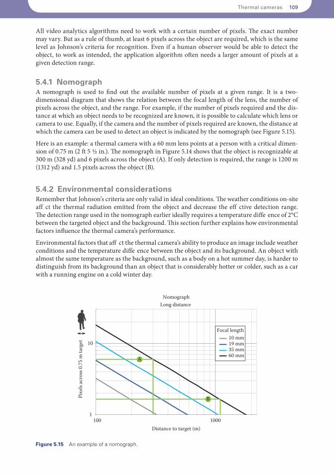
5.4.1 NomographA nomograph is used to find out the available number of pixels at a given range. It is a two- dimensional diagram that shows the relation between the focal length of the lens, the number of pixels across the object, and the range. For example, if the number of pixels required and the dis-tance at which an object needs to be recognized are known, it is possible to calculate which lens or camera to use. Equally, if the camera and the number of pixels required are known, the distance at which the camera can be used to detect an object is indicated by the nomograph (see Figure 5.15).
Here is an example: a thermal camera with a 60 mm lens points at a person with a critical dimen-sion of 0.75 m (2 ft 5 ½ in.). The nomograph in Figure 5.14 shows that the object is recognizable at 300 m (328 yd) and 6 pixels across the object (A). If only detection is required, the range is 1200 m (1312 yd) and 1.5 pixels across the object (B).
5.4.2 Environmental considerationsRemember that Johnson’s criteria are only valid in ideal conditions. The weather conditions on-site aff ct the thermal radiation emitted from the object and decrease the eff ctive detection range. The detection range used in the nomograph earlier ideally requires a temperature diffe ence of 2°C between the targeted object and the background. This section further explains how environmental factors influence the thermal camera’s performance.
Environmental factors that aff ct the thermal camera’s ability to produce an image include weather conditions and the temperature diffe ence between the object and its background. An object with almost the same temperature as the background, such as a body on a hot summer day, is harder to distinguish from its background than an object that is considerably hotter or colder, such as a car with a running engine on a cold winter day.
1
10
100 1000
NomographLong distance
Distance to target (m)
Pixe
ls ac
ross
0.7
5 m
targ
et
A
B
10 mm19 mm35 mm60 mm
Focal length
Figure 5.15 An example of a nomograph.
110 Intelligent Network Video: Understanding Modern Surveillance Systems
The two most important environmental factors that aff ct the camera’s image of an object are absorption and scattering. They reduce the thermal radiation that reaches the camera and therefore shortens the distance at which the camera can detect an object. Scattering has a greater eff ct on the loss of thermal radiation than absorption.
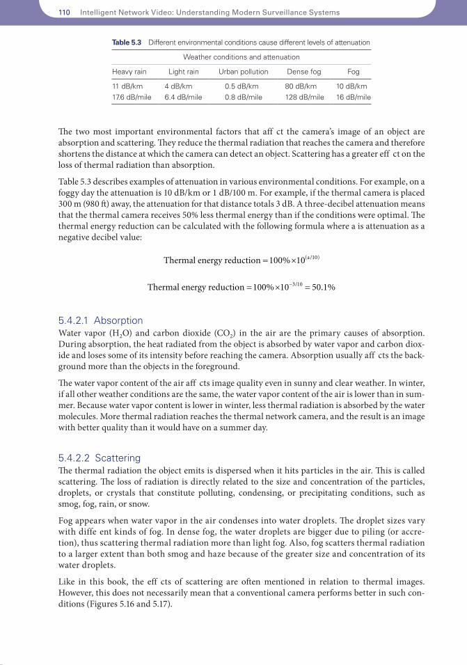
Table 5.3 describes examples of attenuation in various environmental conditions. For example, on a foggy day the attenuation is 10 dB/km or 1 dB/100 m. For example, if the thermal camera is placed 300 m (980 ft) away, the attenuation for that distance totals 3 dB. A three-decibel attenuation means that the thermal camera receives 50% less thermal energy than if the conditions were optimal. The thermal energy reduction can be calculated with the following formula where a is attenuation as a negative decibel value:
Thermal energy reduction a= ´100 10 10% ( / )
Thermal energy reduction = ´ =-100 10 50 13 10% . %/
5.4.2.1 AbsorptionWater vapor (H2O) and carbon dioxide (CO2) in the air are the primary causes of absorption. During absorption, the heat radiated from the object is absorbed by water vapor and carbon diox-ide and loses some of its intensity before reaching the camera. Absorption usually aff cts the back-ground more than the objects in the foreground.
The water vapor content of the air aff cts image quality even in sunny and clear weather. In winter, if all other weather conditions are the same, the water vapor content of the air is lower than in sum-mer. Because water vapor content is lower in winter, less thermal radiation is absorbed by the water molecules. More thermal radiation reaches the thermal network camera, and the result is an image with better quality than it would have on a summer day.
5.4.2.2 ScatteringThe thermal radiation the object emits is dispersed when it hits particles in the air. This is called scattering. The loss of radiation is directly related to the size and concentration of the particles, droplets, or crystals that constitute polluting, condensing, or precipitating conditions, such as smog, fog, rain, or snow.
Fog appears when water vapor in the air condenses into water droplets. The droplet sizes vary with diffe ent kinds of fog. In dense fog, the water droplets are bigger due to piling (or accre-tion), thus scattering thermal radiation more than light fog. Also, fog scatters thermal radiation to a larger extent than both smog and haze because of the greater size and concentration of its water droplets.
Like in this book, the eff cts of scattering are often mentioned in relation to thermal images. However, this does not necessarily mean that a conventional camera performs better in such con-ditions (Figures 5.16 and 5.17).
Table 5.3 Different environmental conditions cause different levels of attenuation
Weather conditions and attenuation
Heavy rain Light rain Urban pollution Dense fog Fog
11 dB/km 4 dB/km 0.5 dB/km 80 dB/km 10 dB/km17.6 dB/mile 6.4 dB/mile 0.8 dB/mile 128 dB/mile 16 dB/mile