Embed Size (px)
Citation preview
Thermal bridging modelling of Ty Unnos junction details
Prepared for: WoodKnowledge Wales March 2012
Report number: 277 519
1 Thermal Bridging modelling of Ty Unnos junction details
BRE report number 278 519 Commercial in confidence
© Building Research Establishment Ltd 2012
Prepared by
Name Caroline Weeks
Position Senior Consultant – BRE Wales
Signature
Reviewed by
Name Colin King
Position Associate Director – BRE Wales
Date 23rd March 2012
Signature
BRE Wales Ethos Kings Road Swansea Waterfront SA1 8AS T + 44 (0) 1792 630100 F + 44 (0) 1792 630101 E [email protected] www.bre.co.uk
This report is made on behalf of BRE. By receiving the report and acting on it, the client - or any third party relying on it - accepts that no individual is personally liable in contract, tort or breach of statutory duty (including negligence).
2 Thermal bridging modelling of Ty Unnos junction details
BRE report number 278 519 Commercial in confidence
© Building Research Establishment Ltd 2012
Executive Summary
BRE Wales were commissioned by WoodKnowledge Wales to carry out modelling on a range of Ty Unnos
construction details in order to calculate the linear thermal transmittance, ψ, of the junctions. This
information is utilised in SAP calculations for compliance with Building Regulations Approved Document
Part L. Thermal bridging data is also used when assessing a building against the Passivhaus standard,
though the conventions used for Passivhaus are different to those used for UK Part L calculations; namely,
junctions are measured to internal dimensions in the UK but to external dimensions for Passivhaus, which
fundamentally changes the thermal bridging/ ψ-values. For this study, ψ-values have been calculated to
both standards. However, care should be taken to ensure the correct values are used for the relevant
circumstances.
The relative complexity of the Ty Unnos construction system, particularly at key junctions where the Ty
Unnos structural beams are present, make the derivation of the whole heat loss from the building more
complex compared to other simpler systems. To truly represent the impact of the construction methodology,
it has been necessary to model additional χ –values to represent occurrences of point thermal bridges. This
report details how each of the following heat loss characteristics should be used in conjunction with each
other for the Ty Unnos system.
Overall, heat loss from any building will be represented by:
- U values, applied over the area of the respective plane elements (W/m2K)
- Ψ-values, applied over the length of the respective junctions (W/m·K)
- χ -values, applied to the number of occurrences of the particular point thermal bridges (W/K)
The ψ-values modelled for the demonstration Ty Unnos house to UK Regulations all fall below the default
values that would otherwise be used for SAP assessments, which will benefit the modelled energy demand
within SAP.
For Passivhaus, junctions with a ψ-value less than 0.01 W/m·K are considered ‘thermal bridge free’ and do
not need to be taken into account within the modelling. However, any junctions above this limit will need to
be represented. While many of the Ty Unnos junctions modelled for Passivhaus actually have negative ψ-
values, the Ground floor/ External wall and Intermediate floor/ External wall junctions do exceed
0.01 W/m·K. Whether or not this is likely to be an issue for a Passivhaus model will depend on many other
factors and how closely the overall building design sits within each of the Passivhaus limiting parameters.
3 Thermal bridging modelling of Ty Unnos junction details
BRE report number 278 519 Commercial in confidence
© Building Research Establishment Ltd 2012
Contents
1 Introduction/ Background 4
1.1 Modelling software and protocols 6 1.2 Assumptions and use of this bridging data 6
2 Linear thermal transmittance (ψ) results 7
1 Ground floor/ External wall junction 7 2 Standard corner 8 3 Intermediate floor/ External wall junction 9 4 Eaves (room in roof) detail 10 5 Gable (room in roof) detail 11 6 Ridge detail 13 7 Head detail 14 8 Sill detail 15 9 Jamb detail 16
3 Point thermal transmittance (χ) results 17
10 3D Ty Unnos vertical beam/ ground floor connection 17 11 3D Ty Unnos beam ‘connecting pin’ junction (4 direction pin) 18 3.1 Sum of the energy loss attributable to the χ-values in the demonstration house 19
4 Discussion 20
4.1 Use of χ-values in SAP or PHPP for Passivhaus 22 4.2 Comparison of modelled ψ-values with the default ψ-values in SAP 2009 23 4.3 Use of ψ-values for Passivhaus PHPP modelling 23
4 Thermal bridging modelling of Ty Unnos junction details
BRE report number 278 519 Commercial in confidence
© Building Research Establishment Ltd 2012
1 Introduction/ Background
Thermal modelling has been carried out on Ty Unnos construction details in order to calculate the linear
thermal transmittance, ψ (pronounced ‘saɪ’), associated with the junctions. This information is utilised in
SAP calculations for compliance with Building Regulations Approved Document Part L. Where the thermal
transmittance for the junctions is not confirmed by modelling, projects will be required to use default values
within SAP that may detrimentally affect the overall energy performance calculated for the building.
Thermal bridging data is also used when assessing a building against the Passivhaus standard, though the
conventions used for Passivhaus are different to those used for UK Part L calculations; namely, junctions
are measured to internal dimensions in the UK but to external dimensions for Passivhaus, which
fundamentally changes the thermal bridging/ ψ-values. For Passivhaus, junctions with a ψ-value less than
0.01 W/m·K are considered ‘thermal bridge free’ and do not need to be taken into account in the overall
heat transfer through the building fabric. However, any junctions above this limit do need to be taken into
account.
There are two effects that can contribute to the linear thermal transmittance of a junction detail and indeed
both effects are often present together. One is a geometric effect that results from internal and external
areas at the junction not being equal or the dimension system used, such as overall internal dimensions.
The other effect is a constructional effect. For example, where the insulation level changes, e.g. a change
in its thickness or thermal conductivity. Construction thermal bridges will also exist where materials with
high thermal conductivity penetrate the insulation layer. Thermal bridges that apply over a defined length,
such as the perimeter of an intermediate floor, are represented as ψ-values. However, in instances where
the additional heat loss applies to a single point rather than acting over a length, it is represented as a χ-
value (pronounced ‘kaɪ’).
Overall, the total heat loss from any building will be represented by:
- U values, applied over the area of the plane elements (W/m2K)
- Ψ-values, applied over the length of each respective junction (W/m·K)
- χ-values, applied to the number of occurrences of a particular point bridge (W/K)
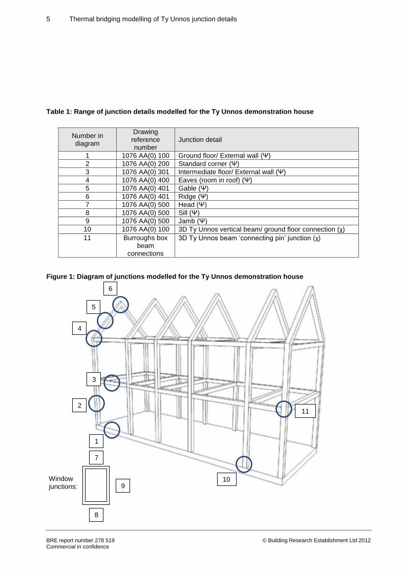
For this project, the following junctions were prioritised, as indicated in Table 1 and Figure 1. The relatively
unusual nature of the construction meant that some junctions required complex 3D modelling in order to
account for the behaviour of the ‘connecting pins’ where the Ty Unnos beams meet, which are represented
as χ-values. The treatment of these additional junctions for SAP and Passivhaus purposes is discussed in
Section 4.
5 Thermal bridging modelling of Ty Unnos junction details
BRE report number 278 519 Commercial in confidence
© Building Research Establishment Ltd 2012
Table 1: Range of junction details modelled for the Ty Unnos demonstration house
Number in diagram
Drawing reference number
Junction detail
1 1076 AA(0) 100 Ground floor/ External wall (Ψ)
2 1076 AA(0) 200 Standard corner (Ψ)
3 1076 AA(0) 301 Intermediate floor/ External wall (Ψ)
4 1076 AA(0) 400 Eaves (room in roof) (Ψ)
5 1076 AA(0) 401 Gable (Ψ)
6 1076 AA(0) 401 Ridge (Ψ)
7 1076 AA(0) 500 Head (Ψ)
8 1076 AA(0) 500 Sill (Ψ)
9 1076 AA(0) 500 Jamb (Ψ)
10 1076 AA(0) 100 3D Ty Unnos vertical beam/ ground floor connection (χ)
11 Burroughs box beam
connections
3D Ty Unnos beam ‘connecting pin’ junction (χ)
Figure 1: Diagram of junctions modelled for the Ty Unnos demonstration house
Window junctions:
6
5
4
3
2
1
10
11
7
9
8
6 Thermal bridging modelling of Ty Unnos junction details
BRE report number 278 519 Commercial in confidence
© Building Research Establishment Ltd 2012
1.1 Modelling software and protocols
This thermal bridging modelling has been done using Physibel’s Trisco (v12) software, and following the
conventions and guidance in BR497, ‘Conventions for calculating linear thermal transmittance and
temperature factors’ (Ward. T & Sanders. C, 2007).
The temperature factor (fRsi) for each junction is also quoted. To limit the risk of surface condensation or
mould growth at junctions the temperature factor should be greater than or equal to a critical value (fCRsi) of
0.75, as quoted in BRE’s Information Paper 1/06, ‘Assessing the effects of thermal bridging at junctions and
around openings’ (Ward. T, 2006).
1.2 Assumptions and use of this bridging data
Information about products and materials used have been provided by the architect and thermal
conductivity values sought from manufacturers literature wherever possible. In the absence of manufacturer
data, generic thermal conductivity values have been used. All relevant material properties associated with
the modelling of the various junctions are given together with the calculated results for each detail. If the
materials to be used during construction differ from these listed materials such that their thermal properties
are different then the calculated ψ-values etc. contained in this report will be invalid. Any change in material
properties will require the particular detail(s) to be re-modelled and a new ψ-value determined.
For a particular building the ψ-values will need to be multiplied by the length over which the particular
junction applies. For example, a thermal bridge calculated at an intermediate floor will need to be multiplied
by the perimeter length of the floor; a thermal bridge calculated at a window head will need to be multiplied
by the length of the window head and so on. The number of occurrences of any point thermal bridge would
need to be totalled and multiplied by the appropriate χ-value, which gives the total heat loss through these
point thermal bridges in W/K.
7 Thermal bridging modelling of Ty Unnos junction details
BRE report number 278 519 Commercial in confidence
© Building Research Establishment Ltd 2012
2 Linear thermal transmittance (ψ) results
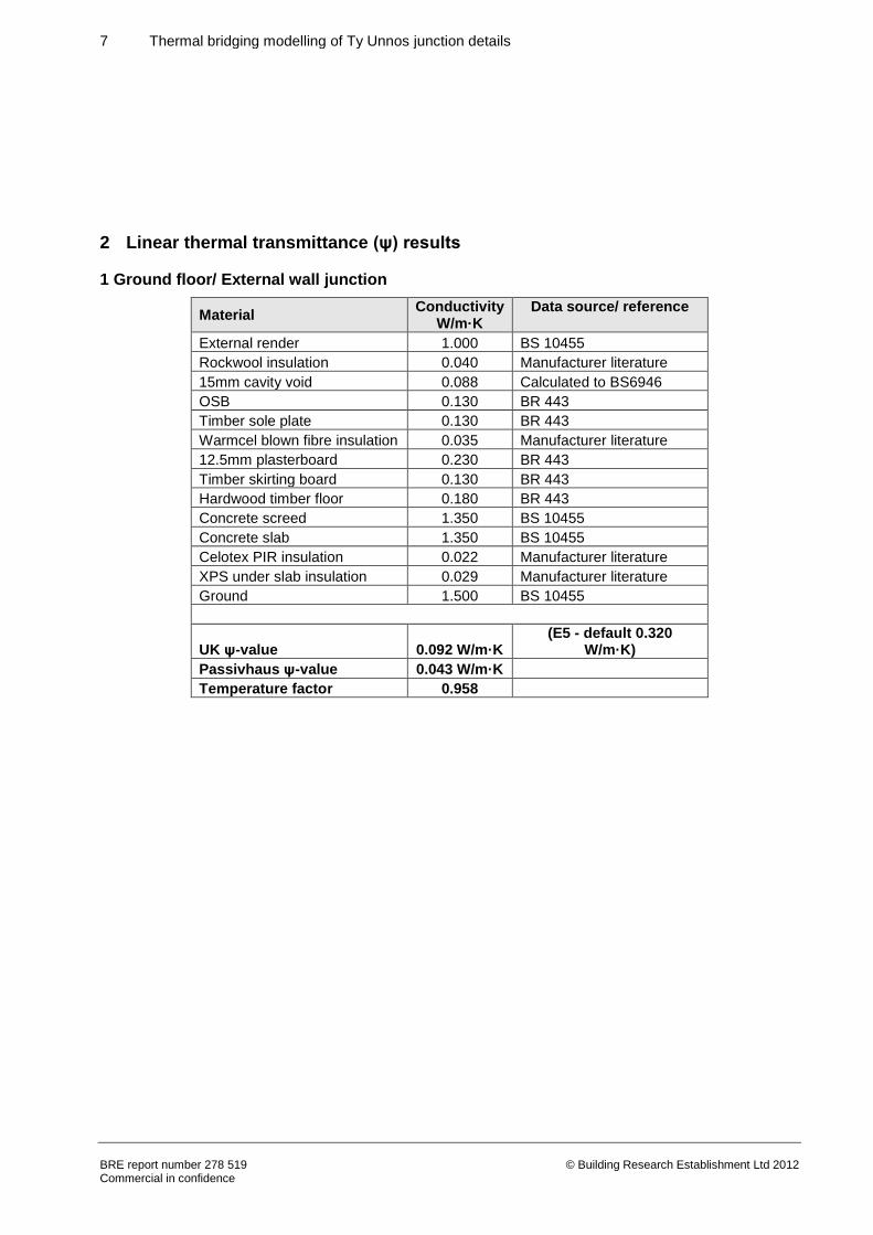
1 Ground floor/ External wall junction
Material Conductivity
W/m·K Data source/ reference
External render 1.000 BS 10455
Rockwool insulation 0.040 Manufacturer literature
15mm cavity void 0.088 Calculated to BS6946
OSB 0.130 BR 443
Timber sole plate 0.130 BR 443
Warmcel blown fibre insulation 0.035 Manufacturer literature
12.5mm plasterboard 0.230 BR 443
Timber skirting board 0.130 BR 443
Hardwood timber floor 0.180 BR 443
Concrete screed 1.350 BS 10455
Concrete slab 1.350 BS 10455
Celotex PIR insulation 0.022 Manufacturer literature
XPS under slab insulation 0.029 Manufacturer literature
Ground 1.500 BS 10455
UK ψ-value 0.092 W/m·K (E5 - default 0.320
W/m·K)
Passivhaus ψ-value 0.043 W/m·K
Temperature factor 0.958
8 Thermal bridging modelling of Ty Unnos junction details
BRE report number 278 519 Commercial in confidence
© Building Research Establishment Ltd 2012
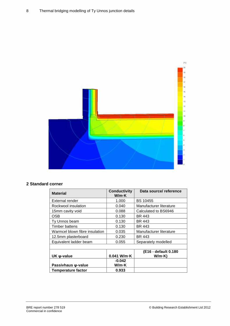
2 Standard corner
Material Conductivity
W/m·K Data source/ reference
External render 1.000 BS 10455
Rockwool insulation 0.040 Manufacturer literature
15mm cavity void 0.088 Calculated to BS6946
OSB 0.130 BR 443
Ty Unnos beam 0.130 BR 443
Timber battens 0.130 BR 443
Warmcel blown fibre insulation 0.035 Manufacturer literature
12.5mm plasterboard 0.230 BR 443
Equivalent ladder beam 0.055 Separately modelled
UK ψ-value 0.041 W/m·K (E16 - default 0.180
W/m·K)
Passivhaus ψ-value -0.042 W/m·K
Temperature factor 0.933
9 Thermal bridging modelling of Ty Unnos junction details
BRE report number 278 519 Commercial in confidence
© Building Research Establishment Ltd 2012
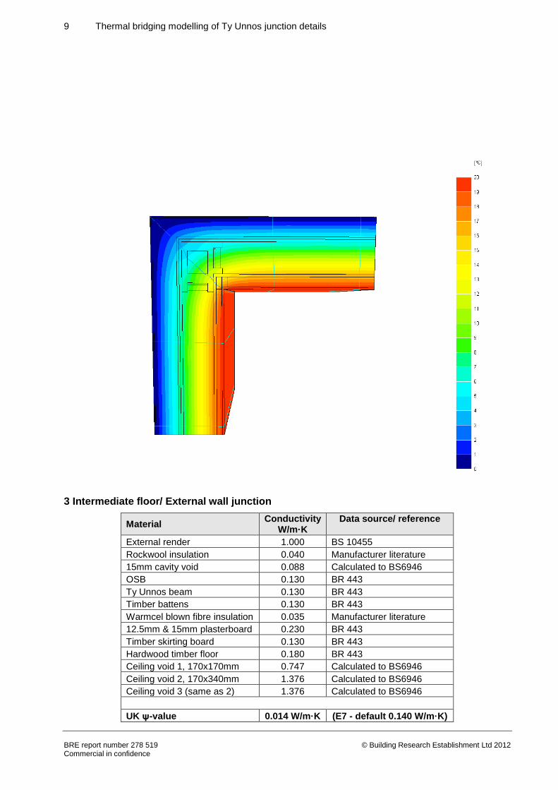
3 Intermediate floor/ External wall junction
Material Conductivity
W/m·K Data source/ reference
External render 1.000 BS 10455
Rockwool insulation 0.040 Manufacturer literature
15mm cavity void 0.088 Calculated to BS6946
OSB 0.130 BR 443
Ty Unnos beam 0.130 BR 443
Timber battens 0.130 BR 443
Warmcel blown fibre insulation 0.035 Manufacturer literature
12.5mm & 15mm plasterboard 0.230 BR 443
Timber skirting board 0.130 BR 443
Hardwood timber floor 0.180 BR 443
Ceiling void 1, 170x170mm 0.747 Calculated to BS6946
Ceiling void 2, 170x340mm 1.376 Calculated to BS6946
Ceiling void 3 (same as 2) 1.376 Calculated to BS6946
UK ψ-value 0.014 W/m·K (E7 - default 0.140 W/m·K)
10 Thermal bridging modelling of Ty Unnos junction details
BRE report number 278 519 Commercial in confidence
© Building Research Establishment Ltd 2012
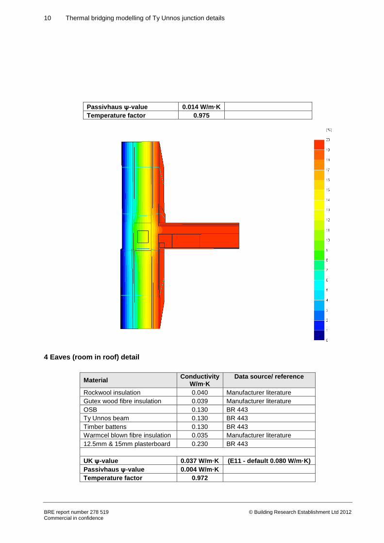
Passivhaus ψ-value 0.014 W/m·K
Temperature factor 0.975
4 Eaves (room in roof) detail
Material Conductivity
W/m·K Data source/ reference
Rockwool insulation 0.040 Manufacturer literature
Gutex wood fibre insulation 0.039 Manufacturer literature
OSB 0.130 BR 443
Ty Unnos beam 0.130 BR 443
Timber battens 0.130 BR 443
Warmcel blown fibre insulation 0.035 Manufacturer literature
12.5mm & 15mm plasterboard 0.230 BR 443
UK ψ-value 0.037 W/m·K (E11 - default 0.080 W/m·K)
Passivhaus ψ-value 0.004 W/m·K
Temperature factor 0.972
11 Thermal bridging modelling of Ty Unnos junction details
BRE report number 278 519 Commercial in confidence
© Building Research Establishment Ltd 2012
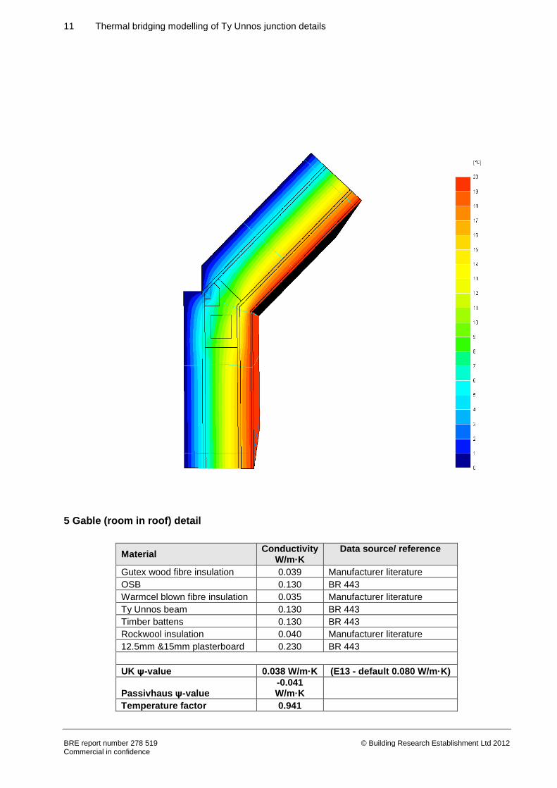
5 Gable (room in roof) detail
Material Conductivity
W/m·K Data source/ reference
Gutex wood fibre insulation 0.039 Manufacturer literature
OSB 0.130 BR 443
Warmcel blown fibre insulation 0.035 Manufacturer literature
Ty Unnos beam 0.130 BR 443
Timber battens 0.130 BR 443
Rockwool insulation 0.040 Manufacturer literature
12.5mm &15mm plasterboard 0.230 BR 443
UK ψ-value 0.038 W/m·K (E13 - default 0.080 W/m·K)
Passivhaus ψ-value -0.041 W/m·K
Temperature factor 0.941
12 Thermal bridging modelling of Ty Unnos junction details
BRE report number 278 519 Commercial in confidence
© Building Research Establishment Ltd 2012
13 Thermal bridging modelling of Ty Unnos junction details
BRE report number 278 519 Commercial in confidence
© Building Research Establishment Ltd 2012
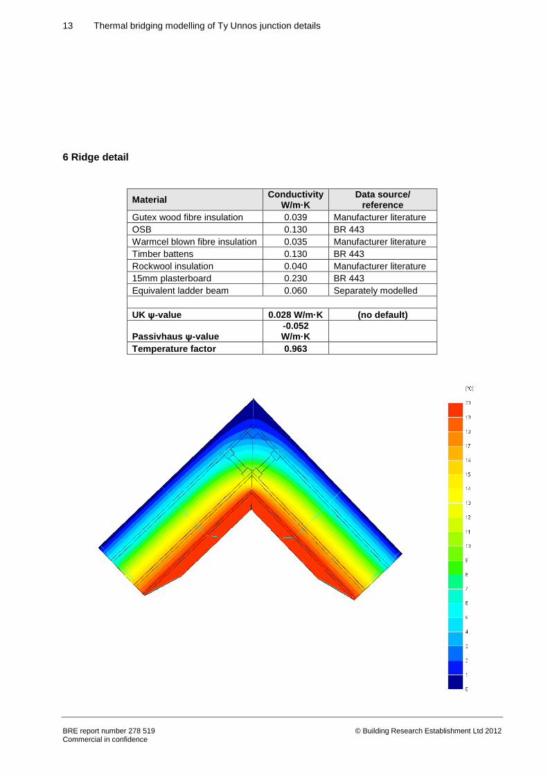
6 Ridge detail
Material Conductivity
W/m·K Data source/
reference
Gutex wood fibre insulation 0.039 Manufacturer literature
OSB 0.130 BR 443
Warmcel blown fibre insulation 0.035 Manufacturer literature
Timber battens 0.130 BR 443
Rockwool insulation 0.040 Manufacturer literature
15mm plasterboard 0.230 BR 443
Equivalent ladder beam 0.060 Separately modelled
UK ψ-value 0.028 W/m·K (no default)
Passivhaus ψ-value -0.052 W/m·K
Temperature factor 0.963
14 Thermal bridging modelling of Ty Unnos junction details
BRE report number 278 519 Commercial in confidence
© Building Research Establishment Ltd 2012
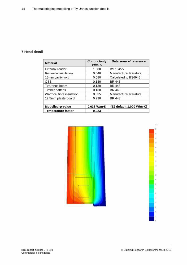
7 Head detail
Material Conductivity
W/m·K Data source/ reference
External render 1.000 BS 10455
Rockwool insulation 0.040 Manufacturer literature
15mm cavity void 0.088 Calculated to BS6946
OSB 0.130 BR 443
Ty Unnos beam 0.130 BR 443
Timber battens 0.130 BR 443
Warmcel fibre insulation 0.035 Manufacturer literature
12.5mm plasterboard 0.230 BR 443
Modelled ψ-value 0.038 W/m·K (E2 default 1.000 W/m·K)
Temperature factor 0.923
15 Thermal bridging modelling of Ty Unnos junction details
BRE report number 278 519 Commercial in confidence
© Building Research Establishment Ltd 2012
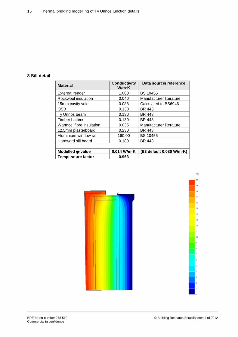
8 Sill detail
Material Conductivity
W/m·K Data source/ reference
External render 1.000 BS 10455
Rockwool insulation 0.040 Manufacturer literature
15mm cavity void 0.088 Calculated to BS6946
OSB 0.130 BR 443
Ty Unnos beam 0.130 BR 443
Timber battens 0.130 BR 443
Warmcel fibre insulation 0.035 Manufacturer literature
12.5mm plasterboard 0.230 BR 443
Aluminium window sill 160.00 BS 10455
Hardword sill board 0.180 BR 443
Modelled ψ-value 0.014 W/m·K (E3 default 0.080 W/m·K)
Temperature factor 0.963
16 Thermal bridging modelling of Ty Unnos junction details
BRE report number 278 519 Commercial in confidence
© Building Research Establishment Ltd 2012
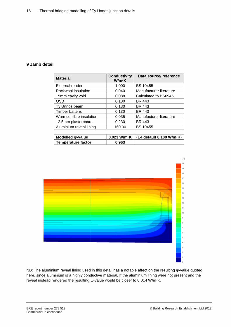
9 Jamb detail
Material Conductivity
W/m·K Data source/ reference
External render 1.000 BS 10455
Rockwool insulation 0.040 Manufacturer literature
15mm cavity void 0.088 Calculated to BS6946
OSB 0.130 BR 443
Ty Unnos beam 0.130 BR 443
Timber battens 0.130 BR 443
Warmcel fibre insulation 0.035 Manufacturer literature
12.5mm plasterboard 0.230 BR 443
Aluminium reveal lining 160.00 BS 10455
Modelled ψ-value 0.023 W/m·K (E4 default 0.100 W/m·K)
Temperature factor 0.963
NB: The aluminium reveal lining used in this detail has a notable affect on the resulting ψ-value quoted
here, since aluminium is a highly conductive material. If the aluminium lining were not present and the
reveal instead rendered the resulting ψ-value would be closer to 0.014 W/m·K.
17 Thermal bridging modelling of Ty Unnos junction details
BRE report number 278 519 Commercial in confidence
© Building Research Establishment Ltd 2012
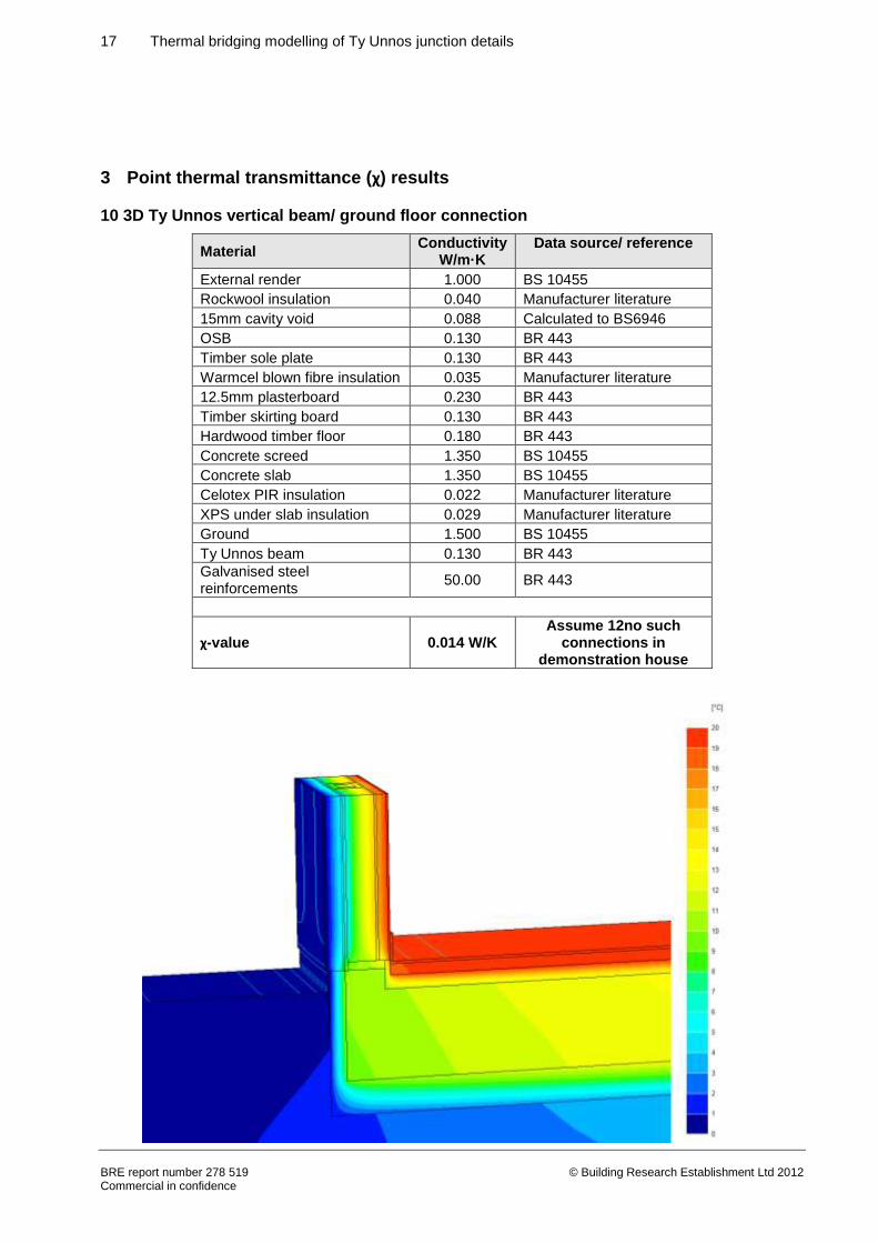
3 Point thermal transmittance (χ) results
10 3D Ty Unnos vertical beam/ ground floor connection
Material Conductivity
W/m·K Data source/ reference
External render 1.000 BS 10455
Rockwool insulation 0.040 Manufacturer literature
15mm cavity void 0.088 Calculated to BS6946
OSB 0.130 BR 443
Timber sole plate 0.130 BR 443
Warmcel blown fibre insulation 0.035 Manufacturer literature
12.5mm plasterboard 0.230 BR 443
Timber skirting board 0.130 BR 443
Hardwood timber floor 0.180 BR 443
Concrete screed 1.350 BS 10455
Concrete slab 1.350 BS 10455
Celotex PIR insulation 0.022 Manufacturer literature
XPS under slab insulation 0.029 Manufacturer literature
Ground 1.500 BS 10455
Ty Unnos beam 0.130 BR 443
Galvanised steel reinforcements
50.00 BR 443
χ-value 0.014 W/K Assume 12no such
connections in demonstration house
18 Thermal bridging modelling of Ty Unnos junction details
BRE report number 278 519 Commercial in confidence
© Building Research Establishment Ltd 2012
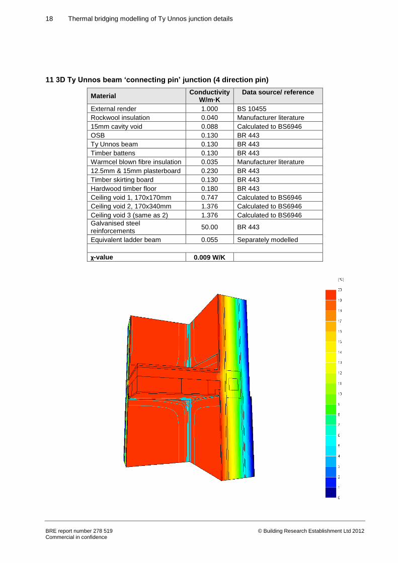
11 3D Ty Unnos beam ‘connecting pin’ junction (4 direction pin)
Material Conductivity
W/m·K Data source/ reference
External render 1.000 BS 10455
Rockwool insulation 0.040 Manufacturer literature
15mm cavity void 0.088 Calculated to BS6946
OSB 0.130 BR 443
Ty Unnos beam 0.130 BR 443
Timber battens 0.130 BR 443
Warmcel blown fibre insulation 0.035 Manufacturer literature
12.5mm & 15mm plasterboard 0.230 BR 443
Timber skirting board 0.130 BR 443
Hardwood timber floor 0.180 BR 443
Ceiling void 1, 170x170mm 0.747 Calculated to BS6946
Ceiling void 2, 170x340mm 1.376 Calculated to BS6946
Ceiling void 3 (same as 2) 1.376 Calculated to BS6946
Galvanised steel reinforcements
50.00 BR 443
Equivalent ladder beam 0.055 Separately modelled
χ-value 0.009 W/K
19 Thermal bridging modelling of Ty Unnos junction details
BRE report number 278 519 Commercial in confidence
© Building Research Establishment Ltd 2012
The connecting pin modelled was a 4 direction pin; locking the Ty Unnos beams into place from above and
below and in each direction into the intermediate floor beams, giving a χ-value of 0.009 W/K. In order to
provide indicative values for 2, 3 or 5 direction pins, it is proposed that the contribution of the pins from the
above model are allocated proportionally to the number of pins in question, i.e. 0.00225 W/K per pin. Hence
for:
2 pins, assume 0.0045 W/K per connecting pin
3 pins, assume 0.0068 W/K per connecting pin
5 pins, assume 0.0113 W/K per connecting pin.
In the demonstration house, it is assumed that there are 6 x 2 pin connections, 8 x 4 pin connections and
16 x 5 pin connections, which would contribute to the overall heat loss of the building in addition to that
represented by the U values and the ψ-values, as indicated in Table 2.
3.1 Sum of the energy loss attributable to the χ-values in the demonstration house
Table 2: Contribution each of the point bridges will make to the overall energy demand of the demonstration house
Point bridge Number of occurrences in demonstration house
χ W/K
Sum total W/K
Ground floor connection 12 0.0140 0.168
2 pin connections (at roof ridge) 6 0.0045 0.027
4 pin connections (at intermediate floor corners and gable corners)
8 0.0090 0.072
5 pin connections (at repeating intermediate floor beams and repeating beams at eaves level)
16 0.0113 0.181
Total 0.448
20 Thermal bridging modelling of Ty Unnos junction details
BRE report number 278 519 Commercial in confidence
© Building Research Establishment Ltd 2012
4 Discussion
Since the combination of U values, ψ-values and χ-values should represent the total heat loss from the
building, it is important that the U values used when assessing the building are calculated appropriately
relative to how these ψ-and χ-values have been calculated. The U values should account for the
contribution from the repeating bridging that occurs at the intermediate Ty Unnos structural beams (those
not at the junctions), in addition to the repeating bridging from ladder ‘cross beams’ present. An example U
value calculation for the wall has been calculated in Table 3.
The bridging effect of the ladder beams within the timber frame panels has been reported by the designer
to offset a 10% proportion of the insulation of the plane elements. This is represented in lines 5a, 6a and 7a
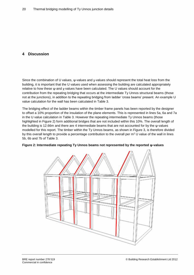
in the U value calculation in Table 3. However the repeating intermediate Ty Unnos beams (those
highlighted in Figure 2) form additional bridges that are not included within this 10%. The overall length of
the building is 12.66m and there are 4 intermediate beams that are not accounted for by the ψ-values
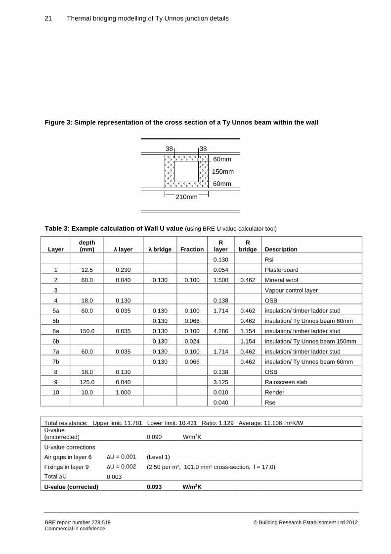
modelled for this report. The timber within the Ty Unnos beams, as shown in Figure 3, is therefore divided
by this overall length to provide a percentage contribution to the overall per m2 U value of the wall in lines
5b, 6b and 7b of Table 3.
Figure 2: Intermediate repeating Ty Unnos beams not represented by the reported ψ-values
21 Thermal bridging modelling of Ty Unnos junction details
BRE report number 278 519 Commercial in confidence
© Building Research Establishment Ltd 2012
Figure 3: Simple representation of the cross section of a Ty Unnos beam within the wall
Table 3: Example calculation of Wall U value (using BRE U value calculator tool)
Layer depth (mm) λ layer λ bridge Fraction
R layer
R bridge Description
0.130 Rsi
1 12.5 0.230 0.054 Plasterboard
2 60.0 0.040 0.130 0.100 1.500 0.462 Mineral wool
3 Vapour control layer
4 18.0 0.130 0.138 OSB
5a 60.0 0.035 0.130 0.100 1.714 0.462 insulation/ timber ladder stud
5b 0.130 0.066 0.462 insulation/ Ty Unnos beam 60mm
6a 150.0 0.035 0.130 0.100 4.286 1.154 insulation/ timber ladder stud
6b 0.130 0.024 1.154 insulation/ Ty Unnos beam 150mm
7a 60.0 0.035 0.130 0.100 1.714 0.462 insulation/ timber ladder stud
7b 0.130 0.066 0.462 insulation/ Ty Unnos beam 60mm
8 18.0 0.130 0.138 OSB
9 125.0 0.040 3.125 Rainscreen slab
10 10.0 1.000 0.010 Render
0.040 Rse
Total resistance: Upper limit: 11.781 Lower limit: 10.431 Ratio: 1.129 Average: 11.106 m²K/W
U-value (uncorrected) 0.090 W/m2K
U-value corrections
Air gaps in layer 6 ΔU = 0.001 (Level 1)
Fixings in layer 9 ΔU = 0.002 (2.50 per m², 101.0 mm² cross-section, l = 17.0)
Total ΔU 0.003
U-value (corrected) 0.093 W/m2K
210mm
60mm
150mm
60mm
38 38
22 Thermal bridging modelling of Ty Unnos junction details
BRE report number 278 519 Commercial in confidence
© Building Research Establishment Ltd 2012
4.1 Use of χ-values in SAP or PHPP for Passivhaus
The presence of the connecting elements that have been modelled to provide χ-values is not readily
captured in SAP 2009 or PHPP for Passivhaus assessments. χ-values are point bridges that do not have a
‘length’ as such. While it would be very easy to dismiss the effect of these point bridges, this modelling
indicates that, due to the nature of the connections for the Ty Unnos structural beams, the U values and ψ-
values alone would underestimate the energy demand of the building by 0.448 W/K. To put this into
perspective, the energy loss associated with the ψ-value of the perimeter length of the intermediate floor
junction would be 0.472 W/K for the demonstration house.
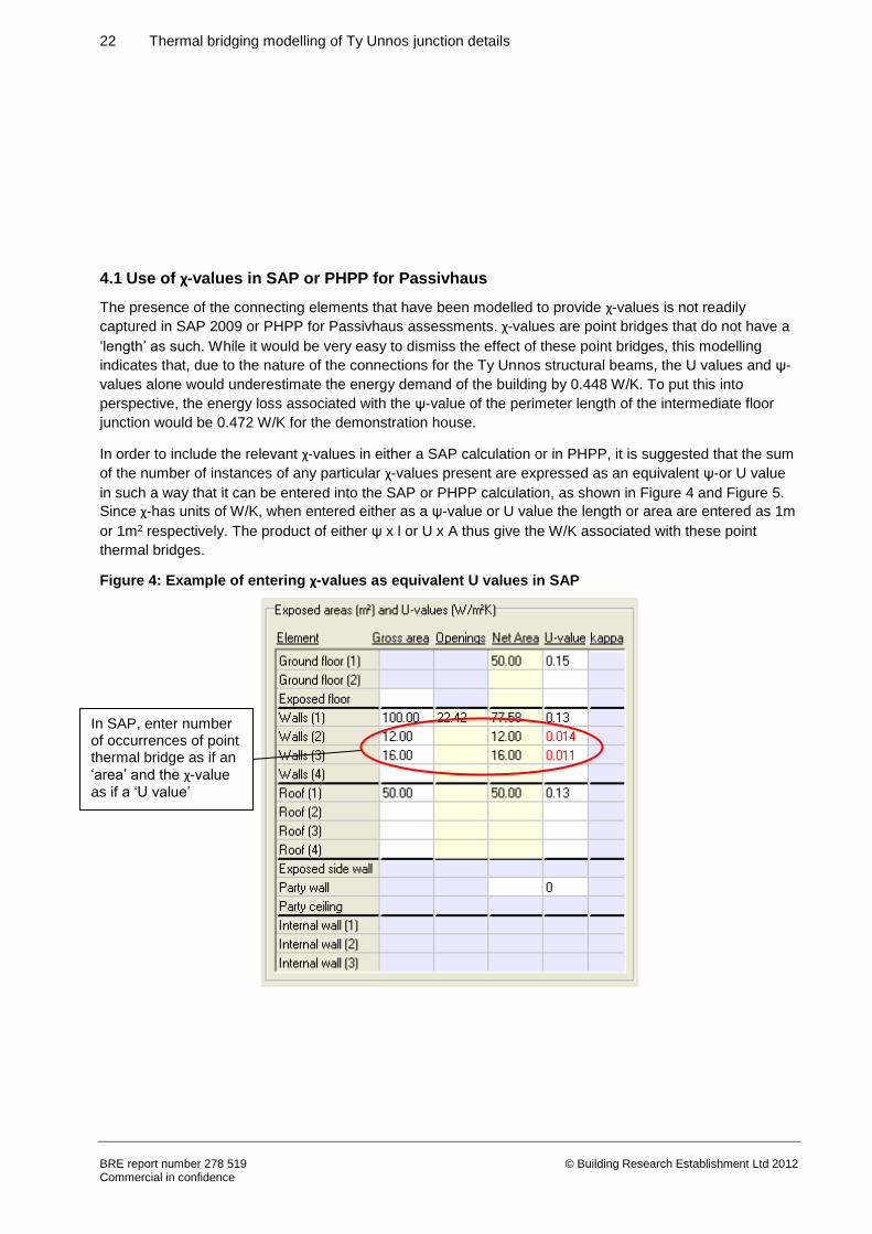
In order to include the relevant χ-values in either a SAP calculation or in PHPP, it is suggested that the sum
of the number of instances of any particular χ-values present are expressed as an equivalent ψ-or U value
in such a way that it can be entered into the SAP or PHPP calculation, as shown in Figure 4 and Figure 5.
Since χ-has units of W/K, when entered either as a ψ-value or U value the length or area are entered as 1m
or 1m2 respectively. The product of either ψ x l or U x A thus give the W/K associated with these point
thermal bridges.
Figure 4: Example of entering χ-values as equivalent U values in SAP
In SAP, enter number of occurrences of point thermal bridge as if an
‘area’ and the χ-value
as if a ‘U value’
23 Thermal bridging modelling of Ty Unnos junction details
BRE report number 278 519 Commercial in confidence
© Building Research Establishment Ltd 2012
Figure 5: Example of entering χ-values as equivalent ψ-values in PHPP
4.2 Comparison of modelled ψ-values with the default ψ-values in SAP 2009
Within the tables in the previous section, the calculated ψ-values for each junction detail are compared with
the default values in SAP. The defaults would need to be used where there is no modelled bespoke
ψ-value available. It can be seen that the modelled junctions have considerably lower ψ-values compared
to the defaults, which will benefit the heat loss calculation in SAP.
4.3 Use of ψ-values for Passivhaus PHPP modelling
In general, the aim within a Passivhaus is for ‘thermal bridge free’ design, which is defined as ψ-values of
less than 0.01 W/m·K, where for Passivhaus external dimensions are used when determining the heat
transfer coefficients. Many of the junctions modelled for this study have (under Passivhaus) ψ-values less
than 0.01 W/m·K and indeed some have negative ψ-values. However other junctions, for example the
ground floor/ external wall junction and intermediate floor/ external wall junction exceed this target, so these
ψ-values would therefore need to be included in the Passivhaus PHPP assessment. It would in fact be
worthwhile to include the negative ψ-values within the PHPP analysis, as they will actually reduce the
overall energy demand from the Passivhaus heat loss calculation.
In PHPP, enter number of occurrences of each point thermal bridge under quantity and the length as 1m
Enter the χ-value
as if a ψ-value


![Bridging Text Spotting and SLAM with Junction Featureskaess/pub/Wang15iros.pdf · reducing false positives. For example, inspired by face and pedestrian detectors [23], Histogram](https://img.pdfslide.us/doc/110x75/5e22ac86b413221fce52c6a0/bridging-text-spotting-and-slam-with-junction-kaesspubwang15irospdf-reducing.jpg)