Embed Size (px)
Citation preview
THERMAL BENDING PLUS TWIST
OPEN SECTION WITH APPLICATION TO GRAVITY GRADIENT BOOMS
OF A THIN-WALLED CYLINDER OF
by Harold P, Frisch
Greenbelt, M d
/
Goddard Space FZight Center , . I
t
N A T I O N A L AERONAUTICS A N D SPACE A D M I N I S T R A T I O N W A S H I N G T O N , D. C. AUGUST 1967
I
https://ntrs.nasa.gov/search.jsp?R=19670025478 2018-06-08T03:57:45+00:00Z
TECH LIBRARY KAFB, NM
I llllll1111111llllllll %I llll lllll Ill Ill OL309b0
NASA TN D-4069
THERMAL BENDING PLUS TWIST O F A THIN-WALLED
CYLINDER O F OPEN SECTION WITH APPLICATION
T O GRAVITY GRADIENT BOOMS
By Harold P. Frisch
Goddard Space Flight Center Greenbelt , Md.
NATIONAL AERONAUTICS AND SPACE ADMINISTRATION -
For sale by the Clearinghouse for Federal Scientific and Technical Information Springfield, Virginia 22151 - CFSTI price $3.00
ABSTRACT
This monograph presents a detailed analysis of the six- dimensional shapes of a particular type of Gravity Gradient boom bent and twisted by the thermal stresses induced by a solar thermal field. Contained within the analysis is a general method of solution, particularly suited for the de- flection analysis of very long thin-walled members of open section having a forcing function that varies along the length and depends on the position and orientation of the cross section relative to a fixed reference frame.
The results given are intended to illustrate the effects of transverse-torsional coupling on the static-thermal- equilibrium shapes of the boom. It is shown that, for the Gravity Gradient boom studied, the thermal equilibrium shape is not unique and that it is not apparent which of the possible shapes are stable. It is thus evident that a planar assumption for thermal bending of any similar Gravity Gradient boom must be strongly justified before it can be assumed credible.
ii
CONTENTS
Abs t r ac t . . . . . . . . . . . . . . . . . . . . . . . . . . . . . . . . . . . . . . . . . . . . . . . . . . . . . . . . ii
INTRODUCTION . . . . . . . . . . . . . . . . . . . . . . . . . . . . . . . . . . . . . . . . . . . . . . . . . . . 1
SYMBOL LIST .................................................... 3
TEMPERATURE DISTRIBUTION ........................................ 6
COORDINATE SYSTEM . . . . . . . . . . . . . . . . . . . . . . . . . . . . . . . . . . . . . . . . . . . . . . 7
THERMAL STRESS . . . . . . . . . . . . . . . . . . . . . . . . . . . . . . . . . . . . . . . . . . . . . . . . . 11
SHEAR STRESS . . . . . . . . . . . . . . . . . . . . . . . . . . . . . . . . . . . . . . . . . . . . . . . . . . . . 1 2
BENDING PLUS TWIST . . . . . . . . . . . . . . . . . . . . . . . . . . . . . . . . . . . . . . . . . . . . . . 1 4
THERMAL TORQUE . . . . . . . . . . . . . . . . . . . . . . . . . . . . . . . . . . . . . . . . . . . . . . . . 1 5
20 NUMERICAL EVALUATION O F BENDING MOMENTS AND TORSIONAL TORQUE . . . . . . EQUATION O F B E N D ~ G . . . . . . . . . . . . . . . . . . . . . . . . . . . . . . . . . . . . . . . . . . . . . 23
RELATIVE SUN POSITION . . . . . . . . . . . . . . . . . . . . . . . . . . . . . . . . . . . . . . . . . . . . 26
METHOD O F SOLUTION ............................................. 27
SOLUTION O F BOUNDARY VALUE PROBLEM .............................. 30
EXTENSIONS O F SOLUTION METHOD . . . . . . . . . . . . . . . . . . . . . . . . . . . . . . . . . . . . 31
FIGURES 7 THROUGH 1 3 A P P L I E D TORQUES. BENDING AND TORSION. VARIABLES OVERLAP . . . . . . . . . . . . . . . . . . . . . . . . . . . . . . . . . . 33
COMMENTS ON FIGURES 7 THROUGH 1 3 ................................. 36
SOLUTIONS T O A PARTICULAR PROBLEM . . . . . . . . . . . . . . . . . . . . . . . . . . . . . . . . RESULTS O F DIGITAL SOLUTION. FIGURES 1 4 THROUGH 25 . . . . . . . . . . . . . . . . . . . 47
36
ANALYTIC SOLUTION T O TORSION EQUATION ............................. 54
CONCLUSIONS .................................................... 59
ACKNOWLEDGMENTS ............................................... 60
Refe rences ....................................................... 60
iii
THERMAL BENDING PLUS TWIST OF A THIN-WALLED CYLINDER OF OPEN SECTION WITH APPLICATION
TO GRAVITY GRADIENT BOOMS
by Harold P. Frisch
Goddard Space Flight Center
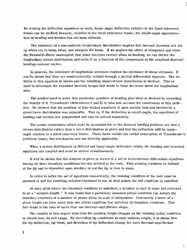
INTRODUCTION
With the advent of Gravity Gradient type satellites, the problem of predicting the motion of extremely long appendages has become important. These appendages a re commonly referred to as "booms" and can usually be classified under the broad title of thin-walled cylinders of open cross section.
Before any attempt can be made to accurately approximate the thermal bending of a boom and incorporate it into a dynamic model of a Gravity Gradient satellite one must first understand what the static thermal equilibrium shape of a boom bent and twisted by thermal stresses will be.
The standard assumption made and used to obtain a first-order approximation of thermal bending is to treat the boom as a seamless cylinder of non-symmetric cross section bent by a definable thermal-stress distribution. The work here discussed treats the cylinder as one of open section; hence, it can take into account the effects of thermal torque and transverse-torsional coupling on thermal bending. It is shown that when the boom is treated as a cylinder of open section, more than one thermal-equilibrium shape may exist and that the trivial solution to the derived set of equations is the zero-twist solution; this is just what would be predicted from the seamless-cylinder assumption.
In order to obtain a numerical solution to the derived equations, a worst-case estimate of the thermal stress distribution about the cross section of a silver-plated DeHavilland-type boom is derived. This is done by stating a set of reasonable assumptions and deriving from them an equa- tion that defines the temperature distribution for any cross-sectional orientation relative to the sun line.
Since the three positional coordinates of the points on the longitudinal axis of the boom are not enough to define the cross-sectional orientation, three rotational coordinates must also be supplied; that is, an additional coordinate system traveling along the booms' length with its axes aligned with the principle axes of inertia of the cross section. This system is related to the fixed system by a set of Euler angles, and the resulting equations of bending and twist are written in terms of them.
1
By writing the deflection equations as such, large-angle deflection relative to the fixed reference frame can be studied; because, relative to the local reference frame, the small-angle approxima- tion of bending and torsion has not been violated.
The existence of a non-uniform temperature distribution implies that thermal stresses are set up which t ry to bend, twist, and elongate the boom. If we neglect the effect of elongation and make the Bernoulli-Euler assumption that plane sections remain plane in bending, we can derive the longitudinal stress distribution and write it as a function of the components of the resultant thermal- bending-moment vector.
In general, the existence of longitudinal s t resses implies the existence of shear stresses. It can be shown that they a re mathematically related through a partial differential equation. The so- lution to this equation is shown and the resulting shear-stress distribution is derived. This is used to determine the resultant thermal torque that tends to twist the boom about the longitudinal axis.
The method used to solve this particular problem of bending plus twist is derived by extending the results of S. Timoshenko (References 1 and 2) to take into account the constraints of this prob- lem. He showed that the problem of thin-walled members of open section bent and twisted by a given force distribution was separable. That is, if the deflection is small-angle, the equations of bending and torsion are independent and may be solved separately.
The prime constraints which must be accounted for in the thermal bending problem are that a s t ress distribution rather than a force distribution is given and that the deflection will be large- angle relative to a fixed reference frame. These facts violate the initial assumption of Timoshenko's problem; hence, his conclusions are not directly applicable.
When a stress distribution is defined and large-angle deflection exists, the bending and torsional equations a re coupled and must be solved simultaneously.
It will be shown that the solution is given in te rms of a se t of simultaneous differential equations having all their boundary conditions but one defined at the root. This missing condition is defined at the tip and is dependent upon whether or not the tip is free to warp.
In order to solve the set of equations numerically, the missing condition at the root must be guessed at and the resulting solution examined to see at what points the end condition is satisfied.
At each point where the boundary condition is satisfied, a solution is said to exist and referred to as a "solution length." It was found that a particular assumed initial condition can satisfy the boundary condition at a number of points along its path of integration. Conversely a boom of a given length can have more than one initial condition that satisfies its boundary condition. This fact leads to the idea of more than one thermal-equilibrium shape.
The results of this report show how the solution length changes as the missing initial condition is varied over its full range. By recording tip conditions at each solution length, i t is shown how the tip deflection, tip twist, and direction of tip deflection change for each thermal-equilibrium
2
shape. The entire deflection pattern of a 100-ft boom is also shown for selected thermal equilibrium shapes and sun orientations.
In order to interpret these results correctly it must be remembered that the bending and torsion equations are coupled and that the direction of deflection at any point depends on past history as well as local stress conditions.
F'urthermore, this report contains a general algorithm that may be used to solve similar prob- lems. The mode of presentation is designed to help the reader determine where he must make modifications in order to incorporate the constraints of his particular problem.
SYMBOL LIST
[AI = coordinate transformation matrix
EM, ( Z ) = thermal bending moment about X, ( Z ) body axis at z
EM, ( z ) = thermal bending moment about Y, ( z ) body axis at
c = torsional rigidity
c, = warping rigidity
E = Young's modulus of elasticity
e = distance between geometrical center and shear center of cross section
ec = coefficient of thermal expansion
C = shear modulus
[T, 7, I;] = orthonormal set of basis vectors parallel to axes of body triad [x, (z) , Y, (z),
z, ( .)I, respectively, but having their origin at = 0
[ T,, y , , G, ] = orthonormal set of basis vectors fixed in inertial triad and parallel to ( X, , Y, , z l ) respectively
I, = geometrical moment of inertia about X, ( z ) body axis
I, = geometrical moment of inertia aboutY, ( z ) body axis
J, = solar radiation intensity
K = thermal conductivity
L = total length of boom (solution length)
- n ( s ) = unit vector in direction of surface normal at position s
3

P = total perimeter of cross section
Q( z), v( Z ) = quantities used to determine thermal torque coefficient
r = radius of cross section
R( z)' = magnitude of deflection of point z on boom measured in X I , Y, plane
s = arc length measured from outer to inner seam around cross section
4
SL = unit vector parallel to sun line
t = thickness of cross section
T ( ~ , z ) = temperature (absolute) at point ( s , z) on boom surface
T, ( z ) = mean temperature of cross section at z
To = ambient temperature
Tsc ( z ) = thermal torque due to shea r stress distribution at z
x, = axis parallel to principal axis of inertia at z = 0 oriented so that (x, , Y , , z, is right-handed system, outer seam in positive X, region for A = -1, outer seam in negative X , region for A = +1
(x, , Y, , z,) = inertial triad
x, = principal axis of inertia normal to Y, ( z ) in plane of cross section, outer seam in positive X, ( z ) region for A = -1, outer seam in negative x, ( z )
region for x = +1
X, ( s ) = X , ( z ) coordinate of point s on cross section
[x, ( z ) , Y, ( z ) , Z , ( z ) ] = body triad at z, principal axes of inertia
Y, = axis parallel to mass symmetry axis of cross section at z = 0, A = +1 o r -1, overlap in negative Y region
Y , ( z ) = mass symmetry axis of c ross section, overlap in negative Y, (.) region
y, ( s ) = Y , ( z ) coordinate of point s on cross section
for A = +1 or -1
z, = axis tangent to centroidal axis a t z = 0, positive in direction of increasing
Z, ( z ) = principal axis of inertia tangent to centroidal axis at z in direction of in- creasing z
z = a rc length measured along centroidal axis from root to tip
4
as = absorptivity
6 = distance between geometrical center and centroid of cross section
E = emmissivity of surface
E~ ( s , Z ) = thermal strain at ( s , Z)
o = direction of bending if zero twist bending existed, normal to neutral axis
B ( Z ) = direction of deflection, i.e., inclination of R( Z ) from negative Y , axis meas- ured in a right-handed sense
[ 8 , ( z), 8 , (z), cp(z)] = Euler-angle rotation sequence used to define orientation of body triad relative to inertial triad
A = +1 if direction of increasing s is clockwise about positive Z , axis in right- handed sense
h = -1 if direction of increasing s is counterclockwise about positive z, axis in right-handed sense
n - a ( z ) = angle between sun line and z, ( z ) axis a t z
p'<.) = curvature vector at z
px ( z ) , py ( z ) , pz ( z ) = components of curvature vector at z relative to body triad
u = radiation coefficient
C T ~ ( s , Z) = longitudinal thermal s t ress at ( s , Z )
T ( S , Z ) = shear s t ress at ( s , Z )
6 = angular amount of overlap
~ p ( ~ ) = boom twist at z
I = direction of bending if "in plane" bending existed
$Jo, a. = values of +(z) and a ( z ) respectively at z = 0
$I( z) = angle between component of sun line in cross-sectional plane at z and the negative Y, ( Z) axis, measured in direction of increasing s
5
TEMPERATURE DISTRIBUTION
The foundation of any analysis of thermal bending is the accurate description of the tempera- ture distribution in the specimen under study. An extremely accurate description, however, in- evitably leads to equations that can be solved only when simplified.
The thermal equations presented in this section attempt to give a worst-case estimate of the thermal gradients; hence, the second-order effects that tend to reduce the thermal gradients a re neglected. By considering the worst-case estimate, this report will attempt to define the maximum limits of deflection and accent any effects that would not be predictable from a less detailed analysis.
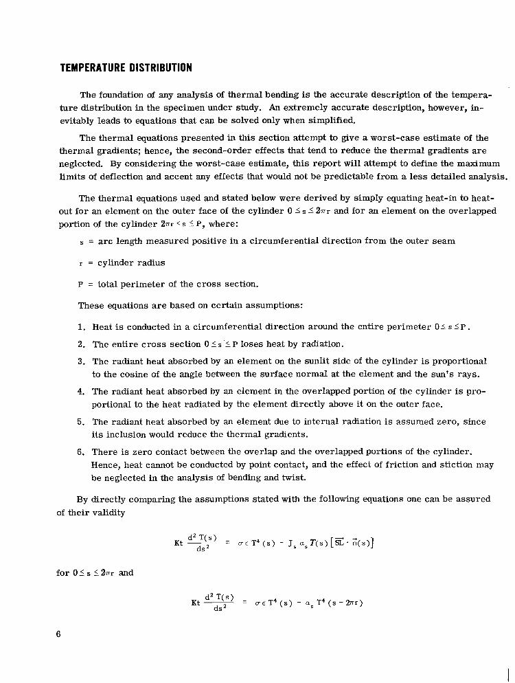
The thermal equations used and stated below were derived by simply equating heat-in to heat- out for an element on the outer face of the cylinder 0 I s I 271r and for an element on the overlapped portion of the cylinder 271r < s 5 P, where:
= arc length measured positive in a circumferential direction from the outer seam
r = cylinder radius
P = total perimeter of the cross section.
These equations a r e based on certain assumptions:
1. Heat is conducted in a circumferential direction around the entire perimeter 01 s IP . 2. The entire cross section 0 IS '5 P loses heat by radiation.
3. The radiant heat absorbed by an element on the sunlit side of the cylinder is proportional to the cosine of the angle between the surface normal at the element and the sun's rays.
4. The radiant heat absorbed by an element in the overlapped portion of the cylinder is pro- portional to the heat radiated by the element directly above it on the outer face.
5. The radiant heat absorbed by an element due to internal radiation is assumed zero, since its inclusion would reduce the thermal gradients.
6. There is zero contact between the overlap and the overlapped portions of the cylinder. Hence, heat cannot be conducted by point contact, and the effect of friction and stiction may be neglected in the analysis of bending and twist.
By directly comparing the assumptions stated with the following equations one can be assured of their validity
for 01 s 52nr and
6
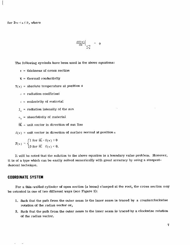
for 2nr < s 5 P, where
The following symbols have been used in the above equations:
t = thickness of cross section
K = thermal conductivity
T( S ) = absolute temperature at position S
D = radiation coefficient
E = emissivity of material
J, =. radiation intensity of the sun
as = absorbtivity of material
SL = unit vector in direction of sun line +
;(s) = unit vector in direction of surface normal at position s
It will be noted that the solution to the above equation is a boundary value problem. However, it is of a type which can be easily solved numerically with great accuracy by using a steepest- descent technique.
COORDINATE SYSTEM
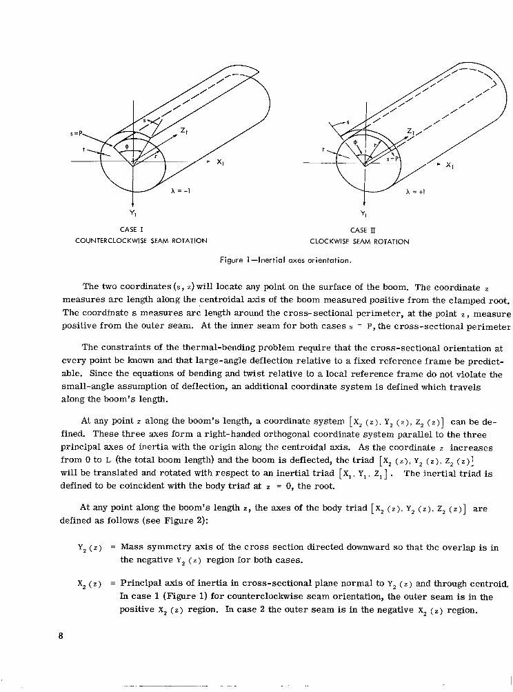
For a thin-walled cylinder of open section (a boom) clamped at the root, the cross section may be oriented in one of two different ways (see Figure 1):
1. Such that the path from the outer seam to the inner seam is traced by a counterclockwise rotation of the radius vector or,
2. Such that the path from the outer seam to the inner seam is traced by a clockwise rotation of the radius vector.
7
V-J x = +1
Yl
CASE I COUNTERCLOCKWISE SEAM ROTATION
i YI
CASE II CLOCKWISE SEAM ROTATION
Figure 1 -Inertial axes orientation.
The two coordinates (s, Z ) will locate any point on the surface of the boom. The coordinate measures a rc length along the centroidal axis of the boom measured positive from the clamped root. The coordinate s measures arc length around the cross- sectional perimeter, at the point z , measure positive from the outer seam. At the inner seam for both cases s = P, the cross-sectional perimeter
The constraints of the thermal-bending problem require that the cross-sectional orientation at every point be known and that large-angle deflection relative to a fixed reference frame be predict- able. Since the equations of bending and twist relative to a local reference frame do not violate the small-angle assumption of deflection, an additional coordinate system is defined which travels along the boom's length.
At any point z along the boom's length, a coordinate system [ X, ( z ) , Y , ( z), z, ( z)] can be de- fined. These three axes form a right-handed orthogonal coordinate system parallel to the three principal axes of inertia with the origin along the centroidal axis. As the coordinate z increases from 0 to L (the total boom length) and the boom is deflected, the triad [X, ( z ) , Y , (z), Z, ( z ) ]
will be translated and rotated with respect to an inertial triad [ X I , Y, , Z1] . The inertial triad is defined to be coincident with the body triad at z = 0, the root.
At any point along the boom's length Z , the axes of the body triad [ X, ( z ) , Y , ( z ) , Z, ( z ) ] are defined as follows (see Figure 2):
Y, ( z ) = Mass symmetry axis of the cross section directed downward so that the overlap is in the negative Y, ( Z ) region for both cases.
x, (z) = Principal axis of inertia in cross-sectional plane normal to Y, ( Z ) and through centroid. In case 1 (Figure 1) for counterclockwise seam orientation, the outer seam is in the positive x, ( Z ) region. In case 2 the outer seam is in the negative x, ( Z ) region.
8
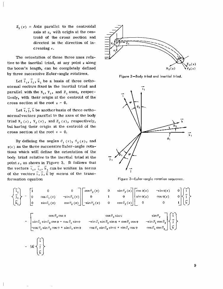
2, ( z ) = Axis parallel to the centroidal axis at Z, with origin at the cen- troid of the cross section and directed in the direction of in- creasing z.
The orientation of these three axes rela- tive to the inertial triad, at any point z along the boom's length, can be completely defined by three successive Euler-angle rotations.
Figure 2-60dy triad and inertial triad.
Let y l , 3, , G l be a basis of three ortho- normal vectors fixed in the inertial triad and &
parallel with the x,, Y,, and z, axes, respec- tively, with their origin at the centroid of the cross section at the root z = 0.
4 - d
Let i, j , k be another basis of three ortho- normalvectors parallel to the axes of the body triad X, ( z ) , Y, ( z ) , and Z, ( z ) , respectively, but having their origin at the centroid of the cross section at the root z = 0.
By defining the angles 0 , ( z ) , 0 , ( z ) , and c p ( z ) as the three successive Euler-angle rota- tions which will define the orientation of the body triad relative to the inertial triad at the point z , as shown in Figure 3. It follows that
4
j l
the vectors i,, 7 T, can be written in terms of the vectors i , j , k' by means of the trans-
- 'I, /- j
formation equation Figure 3-Euler-angle rotation sequence.
cos e , cos cp -cos e, sin cp sine,
- sin e, sin e, cp + cos e, sin cp -sin e, sin e, sin cp + cos e, cos ~p -sin 0, cos e ] E} -I - c o s ~ , s ~ ~ ~ ~ c o s ~ + sine, sinq C O S Q , sin0,sincp + sinB,cosq C O S ~ ~ C O S ~ ,
9
Since [AI is an orthonormal transformation matrix, its inverse is equal to its transpose and hence
At any pa& z along the boom's length the unit vector <* tangent to the centroidal axis is de- fined by the vector equation
where [ X, (z), Y, ( z ) , Z, (z)] are the inertial coordinates of the point z on the centroidal axis of the boom. By definition the vector I; is parallel to <*; hence, from the transformation equation it follows that
4 + - -4 - k* = k s i n 8 , ( z ) i l - s i n 8 , ( z ) c o s 8 , ( z ) j l + C O S ~ ~ ( Z ) C O S ~ , ( Z ) ~ ~ .
Set the components of the vectors <* and < equal to each other and solve the resulting differ- ential equations; the inertial coordinates of any point z along the centroidal axis can then be obtained; that is:
dZ, ( z > dz = COS 8, ( Z ) COS 0, ( Z ) ,
where
The differential equations defining 8, ( z ) and 8 , ( Z) will be derived in the section entitled "Equa- tion of Bending."
10
THERMAL STRESS
The formulation of the equation defining thermal s t ress will be based on the Bernoulli-Euler assumption that plane sections remain plane in bending and that the effects of lateral contraction may be neglected.
It is shown in the theory of thermoelasticity that Hooke's Law must be extended to take into account the effects of thermal expansion (see Reference 3). Thus, the thermoelastic equation for longitudinal thermal stress at a point on the surface of the boom is given by
where
uZ ( s , Z ) = longitudinal thermal stress
c Z ( s , Z ) = longitudinal thermal strain
ec = thermal expansion coefficient
T ( s , Z ) = absolute temperature
To = absolute ambient temperature
E = Young's Modulus of Elasticity.
It should be noted that there is no restriction made on the way the temperature T ( s , Z ) varies around or along the boom. The Bernoulli-Euler assumption that plane sections remain plane in bending, however, requires that the displacement U ( S , Z ) of any point on the cross section be given by a linear function of its X, ( s ) , y, ( S ) body coordinates. Hence, the longitudinal strain must be of the form
E L ( s , z ) = du(s, z )
d Z
where f o ( z ) , f , ( z ) and f , ( z ) are obtainable from the equilibrium conditions. These equilibrium conditions require that the resultant force and moments about the principal axes of the cross section vanish, that is
tuz ( s , z ) ds = tuz ( s , z ) y , ( s ) d s = tuz ( s , z ) x2 ( s ) ds = 0
If we directly substitute and make use of the equilibrium conditions, f ( z ) , f , ( z ) , and f (2) can be derived. It
( s , z), as defined above, in the longitudinal-thermal-stress equation
11
follows that
where
I, = l o p t x : ( s ) d s
BMy(z) = - e c E t JopT(s, z ) x , ( s ) d s .
SHEAR STRESS
It is shown by Timoshenko in Reference 2 and in most books on elasticity that for thin-walled members the shear s t ress T ( S , Z ) is related to the longitudinal stress uz ( s , Z ) by the partial dif- ferential equation
By directly substituting the equation derived f6r thermal stress in this equation, it follows that
The elements of this equation evaluated at point z depend on the temperature distribution, which depends on the relative sun position; this, in its turn, depends on Euler angles 0, ( z ) , 0 , ( Z ) , and Q I ( ~ ) . Therefore, in solving this problem numerically, it is convenient to differentiate with respect to the angle of twist qq Z ) rather then z .
1 2
I
If we apply the chain rule of differential calculus and integrate both sides of the equation from 0 to S , the expression defining shear stress reduces to
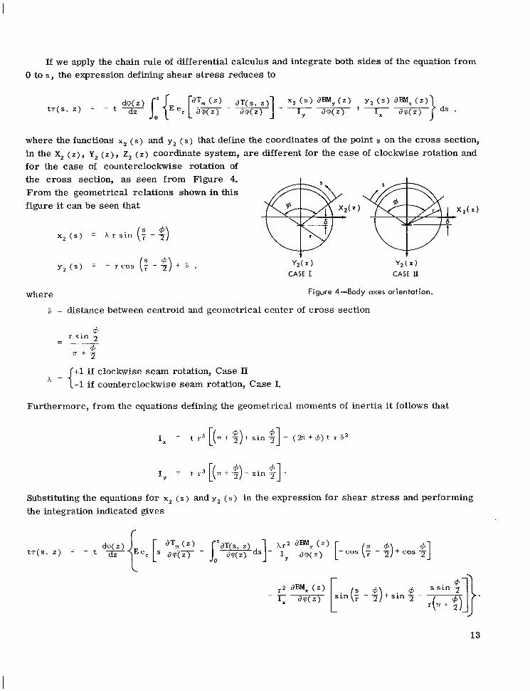
where the functions X, ( s ) and y, ( s ) that define the coordinates of the point s on the cross section, in the x, ( z ) , Y, ( z ) , z, ( z ) coordinate system, are different for the case of clockwise rotation and for the case of counterclockwise rotation of the cross section, as seen from Figure 4. From the geometrical relations shown in this figure it can be seen that
where Figure 4-Body axes orientation.
F = distance between centroid and geometrical center of cross section
4 r s i n 2 +
7 r + - 2
- -
+1 if clockwise seam rotation, Case II -1 if counterclockwise seam rotation, Case I.
Furthermore, from the equations defining the geometrical moments of inertia it follows that
Substituting the equations for x2 ( s ) and y2 ( s ) in the expression for shear s t ress and performing the integration indicated gives
c
13
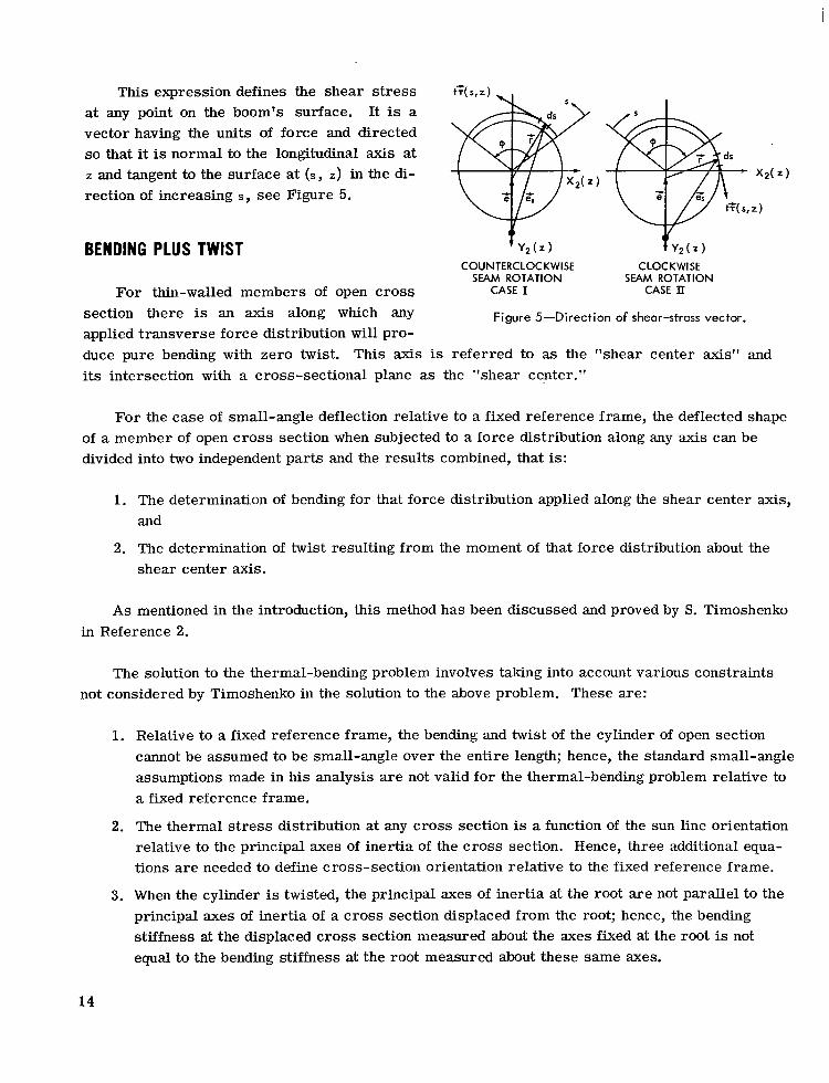
This expression defines the shear stress at any point on the boom's surface. It is a vector having the units of force and directed so that it is normal to the longitudinal axis at z and tangent to the surface at (s, Z) in the di- rection of increasing S, see Figure 5.
tT(s,z) ~*, - X,(Z)
t T ( 5 , Z )
BENDING PLUS TWIST Y , ( z )
COUNTERCLOCKWISE CLOCKWISE SEAM ROTATION SEAM ROTATION
For thin-walled members of open cross CASE I CASE II
Figure 5-Direction of shear-stress vector. section there is an axis along which any applied transverse force distribution will pro- duce pure bending with zero twist. its intersection with a cross-sectional plane as the "shear center."
This axis is referred to as the "shear center axis" and
For the case of small-angle deflection relative to a fixed reference frame, the deflected shape of a member of open cross section when subjected to a force distribution along any axis can be divided into two independent parts and the results combined, that is:
1. The determination of bending for that force distribution applied along the shear center axis, and
2. The determination of twist resulting from the moment of that force distribution about the shear center axis.
As mentioned in the introduction, this method has been discussed and proved by S. Timoshenko in Reference 2.
The solution to the thermal-bending problem involves taking into account various constraints not considered by Timoshenko in the solution to the above problem. These are:
1. Relative to a fixed reference frame, the bending and twist of the cylinder of open section cannot be assumed to be small-angle over the entire length; hence, the standard small-angle assumptions made in his analysis are not valid for the thermal-bending problem relative to a fixed reference frame.
2. The thermal stress distribution at any cross section is a function of the sun line orientation relative to the principal axes of inertia of the cross section. Hence, three additional equa- tions a re needed to define cross-section orientation relative to the fixed reference frame.
3. When the cylinder is twisted, the principal axes of inertia at the root a re not parallel to the principal axes of inertia of a cross section displaced from the root; hence, the bending stiffness at the displaced cross section measured about the axes fixed at the root is not equal to the bending stiffness at the root measured about these same axes.
14
In order to solve the thermal-bending problem, a local coordinate system has been defined at every point along the centroidal axes. Since curvature at every point can be measured with re- spect to these local axes, the standard small-angle assumption of bending and torsion may be em- ployed; Timoshenko's results a re applicable over every element of length, relative to the local axes. Thus, the equations of bending and torsion a re independent over each element of length and may be solved separately. The orientation and position of the local axes relative to the fixed axes at each integration step along the boom's length may be determined by employing the derived co- ordinate transformation equations.
Besides defining the boom's shape in a fixed coordinate system, this information is needed to calculate the appropriate thermal s t ress distribution, which is a function of the relative sun posi- tion at each integration step.
THERMAL TORQUE
S. Timoshenko in Reference 2 shows that for a thin-walled cylinder of open cross section, an applied torque will be balanced partly by the cylinder's torsional rigidity and partly by the cylinder's warping rigidity. This is expressed by the following formula:
Tsc ( 2 ) = - C, p"' ( 2 ) + Cq' ( 2 ) ,
where
TsC ( 2 ) = applied torque
C, = warping rigidity
C = torsional rigidity
c p ( ~ ) = twist, positive about positive Z, ( 2 ) axis.
The boundary conditions associated with these equations a re
and
q" (211 r=L = o , if the tip is free to warp,
q' ( z ) I = o , if the tip is not free to warp.
15

It should be noted that the rate of twist about the Z, ( Z ) body axis as derived from the Euler rate equations is 9' ( z ) + 8,' ( Z ) s i n 8, ( Z ) . However, the factor 8,' ( Z ) s i n 8, ( Z )
approximately equal to zero; hence, the rate about the z, ( z ) body axis is accurately given by 9' ( z ) .
The assumption that this factor is approximately zero follows from the Bernoulli-Euler assumption of bending, which states that the transverse bending moment vector lies in the plane of the cross section (see Section "Equation of Bending").
is assumed to be
In Reference 2 it is further shown that the torsional rigidity c is given by
1 C = 3 P t 3 G ,
where
G = modulus of elasticity in shear
t = thickness of cross section
P = total perimeter of cross section
and the warping rigidity c, is given by
2 , 6[sin - (v + $ ) c o s "]'I
C, = 3 t E r 5 { * + $ ) - , A
where
+ = total angular amount of overlap
P r = = radius of the cylinder of open section.
The applied torque TsC ( z ) may be calculated by integrating the torque due to the shear-stress distribution around any axis normal to the cross section. It will be seen that if the shear center axis is chosen as the axis about which the torque is evaluated, the resulting expression reduces to an equation that is independent of the bending-moment components.
For a cylinder of open section whose diameter remains constant along the length (as has been assumed), the distance e between the shear center and the geocenter of the cross section is given by
This equation is also derived in Reference 2 and many other books on strength of materials.
16
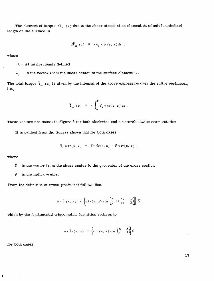
The element of torque d?,, ( Z) due to the shear stress at an element ds of unit longitudinal length on the surface is
d?,, ( z ) = A Z s x'f;(s, z ) d s ,
where
A = &l as previously defined
Zs is the vector from the shear center to the surface element ds .
The total torque Tsc ( 2 ) is given by the integral of the above expression over the entire perimeter, i.e.,
These vectors are shown in Figure 5 for both clockwise and counterclockwise seam rotation.
It is evident from the figures shown that for both cases
where
Z is the vector from the shear center to the geocenter of the cross section
is the radius vector.
From the definition of cross-product it follows that
which by the fundamental trigeometric identities reduces to
Z X < T ( S , 2)
for both cases.
17
I

I
Dropping the vector notation used above (which is no longer needed since f,, is parallel to g) and directly substituting in the total torque integral gives
TSC ( z ) = k e I t - r ( s , z )cos ( + - $ ) d s + X r t - r (s , z ) d s , IoP where
In order to evaluate the above integral, the following definite integrals must be used:
P I cos (: - $) s iu (: - $) ds = 0 0
I’ cos (3 - $)ds = 2r s i n 2 4 0
along with the shear center equation
e = P
18
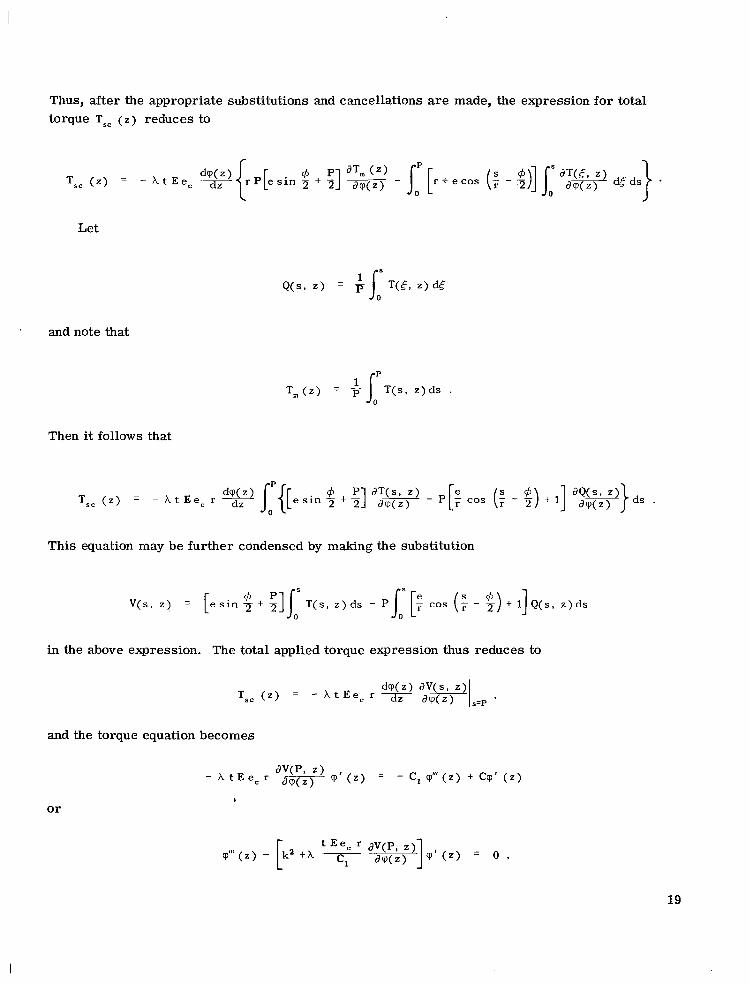
Thus, after the appropriate substitutions and cancellations are made, the expression for total torque TSC ( z ) reduces to
Let
and note that
T m ( z ) = + I o p T ( s , z ) d s .
Then it follows that
This equation may be further condensed by making the substitution
in the above expression. The total applied torque expression thus reduces to
and the torque equation becomes
- A t E e , r dv(p, ,jm z, cp' ( 2 ) = - c, q " ' ( z ) + Cq' ( z )
* o r
19
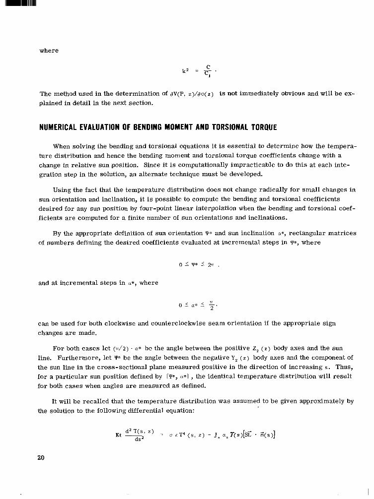
where
The method used in the determination of aV(P, z ) / a q ( Z ) is not immediately obvious and will be ex- plained in detail in the next section.
NUMERICAL EVALUATION OF BENDING MOMENT AND TORSIONAL TORQUE
When solving the bending and torsional equations i t is essential to determine how the tempera- ture distribution and hence the bending moment and torsional torque coefficients change with a change in relative sun position. Since it is computationally impracticable to do this at each inte- gration step in the solution, an alternate technique must be developed.
Using the fact that the temperature distribution does not change radically for small changes in sun orientation and inclination, it is possible to compute the bending and torsional coefficients desired for any sun position by four-point linear interpolation when the bending and torsional coef- ficients a re computed for a finite number of sun orientations and inclinations.
By the appropriate definition of sun orientation Y* and sun inclination a*, rectangular matrices of numbers defining the desired coefficients evaluated at incremental steps in Y*, where
and at incremental steps in a*, where
can be used for both clockwise and counterclockwise seam orientation if the appropriate sign changes are made.
For both cases let ( d 2 ) - a* be the angle between the positive 2, ( Z ) body axes and the sun line. Furthermore, let Y* be the angle between the negative Y, ( 2 ) body axes and the component of the sun line in the cross-sectional plane measured positive in the direction of increasing S. Thus, for a particular sun position defined by [I*, a*] , the identical temperature distribution will result for both cases when angles a re measured as defined.
It will be recalled that the temperature distribution was assumed to be given approximately by the solution to the following differential equation:
20
--.._. ...... .. .. . . .. ...-. ...
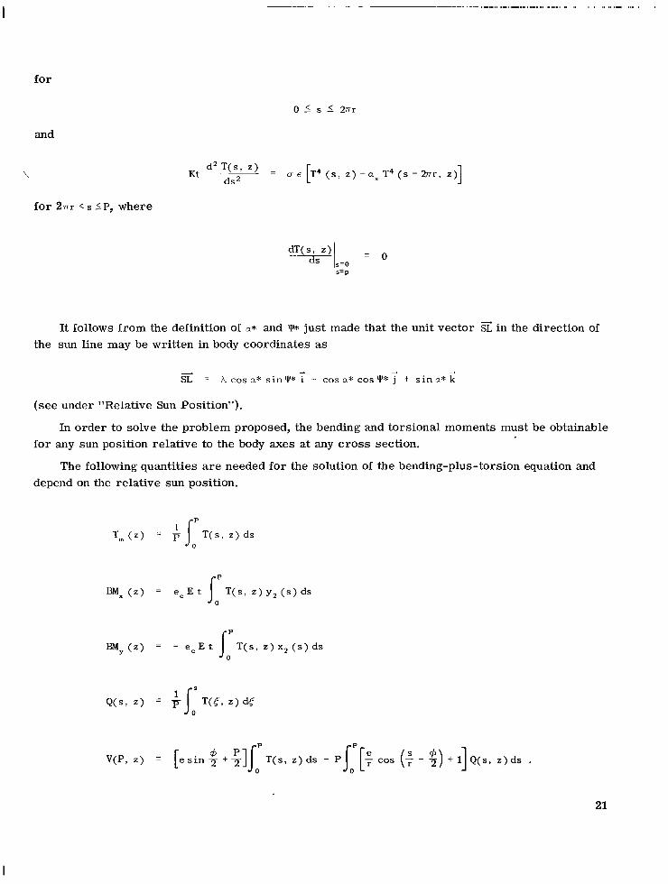
for
and
'.
for 27rr < s 'P, where
d 2 T ( s , z) - - ( s , ~ ) - a ~ T 4 ( s - m r , Kt d s 2
s= p
It follows from the definition of a* and Y* just made that the unit vector in the direction of the sun line may be written in body coordinates as
+ 4 + < = A cosa* sin"* i - cos a* COSY* j + s i n a * k
(see under "Relative Sun Position").
In order to solve the problem proposed, the bending and torsional moments must be obtainable for any sun position relative to the body axes at any cross section.
The following quantities a re needed for the solution of the bending-plus-torsion equation and depend on the relative sun position.
Tm ( z ) = JopT(s, z) ds
v(P, z) = [ e s i n 9 ' +111, T(s , z) ds - P,,'[: cos (: - 1) + I] Q ( s , z) ds .
21
I
The numerical value of each can be ascertained by solving the differential equations defining them simultaneously with the temperature-distribution equation and evaluating each at s = P, i.e.,
my ( s , z) = - e, E t T(s, z ) x 2 (s) ds
where
Incrementally varying Y* and a*, in an appropriate manner, gives a sufficiently dense distri- bution for each of the quantities, so that their values at any sun position can be accurately evaluated by interpolation.
It was shown that the torsional torque was dependent upon the partial derivative of V(P, Z ) with respect to twist ~ ( 2 ) . In order to derive a matrix of numbers which defines this quantity, V(P, Z ) is numerically differentiated with respect to I* and the result is stored. This quantity is related to the desired quantity by the equation
I
A function $(z) analogous to Y* will be derived under "Relative Sun Position." From this expres- sion it can be shown that for small-angle deflection
where $o is the orientation of the sun at z = 0. It is a constant defined initially; hence,
22

But since $( Z ) is analogous to Y* one may write
If large-angle deflection is anticipated, the function $(z) can easily be differentiated with respect to T ( Z ) and must be introduced into the torsional equation. This must be done if booms several hundred feet long are to be studied.
EQUATION OF BENDING
Under "Coordinate System" it was shown that the Euler angles 8 , ( Z ) , 8, ( Z ) and cp( Z ) com- pletely define the orientation of the cross section located at distance z from the origin ( Z being measured along the boom's longitudinal axis).
From the elementary theory of bending it is known that the bending moment at a point along the boom's length is proportional to the boom's curvature at that point. Let Z ( Z ) be the curvature vector at any point along the boom's length. In terms of the inertial triad, its magnitude and direction will be given by 0
Making use of the coordinate transformation defined previously, it is possible to write this vector in terms of the body axes [ y , T, z]; that is
- Z ( z ) = Px (2) i + Py (4 + Pz (4 '
Since by the Bernoulli-Euler assumption section, the T; component of curvature pz
Pz ( 2 ) =
the bending moment vector lies in the plane ( z ) is approximately equal to zero; i.e.,
(Note: this is the identical assumption made under "Thermal Torque.")
Hence,
of the cross
23
where
Thus 0 ( z ) and e, ( z can be obtained from the solution to the differential equations
where expressions for px ( z ) and py (z) will be derived.
At a particular cross section the thermal stress was shown to be b
Hence the thermal strain, i.e., the longitudinal extension of the point xZ ( s ) , y2 ( s ) on the cross section, is
where the quantity ec [Tm ( Z ) - To] is analogous to the tension term that ar ises in the derivation of the equation of bending when bending and tension a re considered (Reference 4, page 162).
In order to determine magnitude and direction of bending, the effect of elongation will be neglected; i.e., it will be assumed that
ec [ T ~ ( ~ ) - T ~ ] 5 o .
Hence the bending s t ress ~2 ( S , Z ) is given by
24
I
where positive bending moment components BM, ( Z ) and BM, ( Z ) will cause positive bending in a right-handed sense about the Y, ( z ) and x, ( Z ) body axes, respectively.
Since bending moment is directly proportional to curvature,
and the differential equations defining 8, ( z ) and 8, ( z ) reduce to:
The bending-moment components as shown are functions of longitudinal arc length z . This is obvious since the sun position relative to the body axes changes as the boom is bent and twisted. Since the sun can be located by the angles +( Z ) and a( z ) , the bending-moment components become functions of these two quantities, thus:
where
77 - - a ( ~ ) = the angle between the sun line and the longitudinal axis at z
$( Z ) = the angle between the component of the sun line in the X, ( Z ) , Y, ( z ) plane and the negative Y, ( z ) axis, measured in the direction of increasing S .
These angles a re easily obtainable by vector techniques and can be defined in terms of e, ( Z ) , 8, ( Z ) , and c p ( z ) , as will be shown.
25
RELATIVE SUN POSITION
Under “Coordinate System” it was shown that the inertial triad (I,, TI, 2,) could be written in terms of the body triad 6, 7 , z) by the transformation equation
and the unit vector i in the direction of the longitudinal axis is defined by
4 -+ 4 4
k = s i n Q 2 ( z ) i l - s i n e 1 ( z ) c o s 8 2 ( z ) j , + C O S ~ ~ ( Z ) C O S ~ ~ ( Z ) ~ ,
written with respect to the inertial triad.
Let
- SL = unit vector directed toward the sun
$0 = +(4z=o a, = “ ( Z ) l r = , .
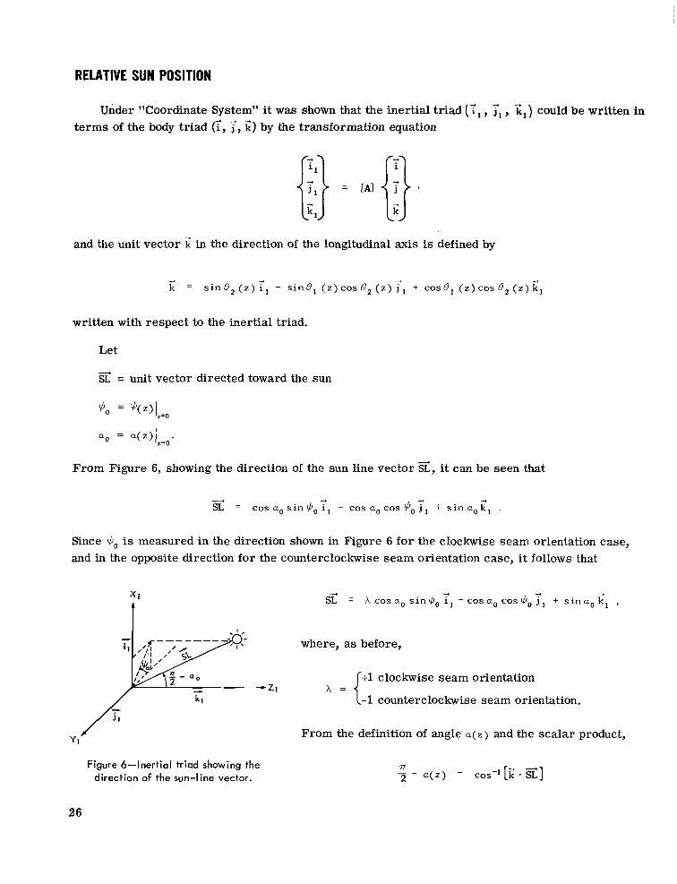
From Figure 6, showing the direction of the sun line vector 5, it can be seen that
d -., 4 - SL = cos a , s i n 3, i, - cos a, cos $, j + s i n a , k,
Since 3, is measured in the direction shown in Figure 6 for the clockwise seam orientation case, and in the opposite direction for the counterclockwise seam orientation case, it follows that
- SL = h c o s a o s i n $ , i l + - c o s a , ~ o s ~ , 4 j , + s i n a o k l - ,
where, as before,
+1 clockwise seam orientation
-1 counterclockwise seam orientation. A = {
From the definition of angle a ( z ) and the scalar product,
Figure 6-inertial triad showing the direction of the sun-line vector.
7l - - 2 a ( z ) = cos-l[i; -31
26
o r
7r a ( z > = ~ - c o s ~ ' [ ~ c o s a ~ s i n + ~ s i n ~ , ( z ) + c o s a o ~ o s + o ~ i n 8 1 ( Z ) C O S ~ , ( z ) + s i n a , , c o ~ 8 ~ ( z ) c o s ~ , ( z ) ] .
In order to determine +(z), write the sun vector in terms of the body triad, that is
4 -4 -4
SL = AS, - S, j + S, k ,
where
S, = Acosa,, s in+, , cos8, ( z ) s i n c p ( z ) - COSQ,, cos+,, s i n e , ( z ) s i n B 2 ( z ) s i n c p ( z )
+ cos a,, COS $J,, C O S 8 , ( z ) COS cp(z) - s i n a,, cos 8 , ( z ) s i n e , ( z ) s i n cp(z)
- s i n a,, s i n 8, ( z ) cos ~ ( z )
Then the angle $( Z ) measured as previously defined is given by
With the derivation of the angles +!J( Z ) and a( Z ) defining relative sun position, i t is possible by four-point linear interpolation to determine the bending-moment components and the torsional- torque coefficient at all points along the boom length and hence solve the differential equation.
It should be noted that i f large-angle deflection is to be studied, the function $( Z ) must be dif- ferentiated with respect to cp(z); this term must be introduced into the torsion equation as previ- ously discussed.
METHOD OF SOLUTION
Due to computer time limitations it is convenient to solve the thermal-bending-plus-twist problem in two parts. In part one, the numerical values of the elements of the matrices needed to define the temperature-dependent bending and torsion coefficients are determined. The output re- sults take a form that may be directly read into the computer as input data for part two. In part two the actual bending-plus-twist solution is performed and the desired results are computed outputs.
27
The following is a summary of the equations needed for solution of the problem and a descrip- tion of the particular technique used to generate the results of this report.
The boundary value problem defining the temperature distribution, i.e.,
= o e T 4 ( s , z ) - J, a S T ( s ) [g' . .(.)I d2 T(s , z )
ds K t
for 0 5 s 5 2nr, and
K t ~ d 2 T ( s ' z ) = o ~ [ T 4 ( ~ , ~ ) - a s T 4 ( s - 2 - r r r , z ) ] d s 2
for 2nr< s I p, where
is solved numerically by assuming a full set of initial conditions and matching-end conditions. This can be done with great accuracy on a digital computer by steepest-descent techniques. When the desired solution accuracy is achieved, the equation is solved again, together with the equations defining quantities that will be used in the bending-plus-torsion equations, that is,
28
These quantities are evaluated at s = P and stored in a computer memory. The solution is repeated a finite number of times for values of Y*, in the interval
and for values of a* in the interval
A two-dimensional array of numbers is then obtained for each of the quantities
The function V ( Z ) is further numerically differentiated with respect to Y*; this, too, is stored in computer memory.
The bending-plus-torsional equations are of the boundary value type; in order to determine a solution numerically by the Runge Kutta numerical integration techniques, a full se t of initial con- ditions must be assumed. The boundary value problem is
where
and
if tip is free to warp,
29

o r
if tip is not free to warp.
At each integration step the quantities e, ( Z ) and 8 , ( Z ) are defined; hence, from the previously derived equations, 3( Z ) and a( Z) are obtainable. With 3( Z ) and a( Z ) given it is possible by four- point interpolation to determine the forcing functions BM, ( 2 ) , BM, (z), and dV(z)/acp(z) for any relative sun position.
The coordinates of any point on the boom in inertial space can be determined from the solution to the differential equations:
dY, ( 2 ) dz = - s i n e 1 ( Z ) C O S e2 ( z )
where
0
If large-angle deflection is anticipated, the torsional equation given above will no longer be valid, since the effect of bending on relative sun position has been assumed small. In order to cor- rect this, the following equation must be used in its place:
where d$(z) /aq(z) is determined directly from the expression for # ( z ) and dV(z)/d+(z) is de- termined directly by four-point interpolation of the appropriate numbers in the matrix defining dV( z)/dY*.
SOLUTION OF BOUNDARY VALUE PROBLEM
The simultaneous differential equations defined in the previous section a re of the boundary value type. All boundary conditions except one are defined at the root z = 0. The one condition
30
I II
defined at the tip is
rp‘l ( z )
cp’ ( z )
= 0 , if tip is free to warp,
= 0 , if tip is not free to warp.
I =L
I =L
In order to obtain a solution for a boom of length^, the initial condition cp” ( 0 ) must be determined by a p,redictor-corrector or steepest-descent technique. It was found that this was not easily done; another approach had to be taken.
The method used was simply to define an initial condition cp” (0) and carry the integration out with respect to z to some predefined point. The function rp” ( z ) (or cp’ ( z ) ) was then examined for zero crossing. For each value of z for which rp“ ( Z ) (or cp’ ( z ) ) was equal to zero, the boundary condition was satisfied and a solution was said to exist for that particular boom length. If for a particular value of cp” (0) , rp” ( z ) (or rp‘ ( z ) ) was equal to zero at a number of points along Z , the implication was that the same initial condition gave a solution for more than one boom length. Conversely, it is implied that if more than one boom length has the identical initial conditions, then a particular boom length can have a solution for more than one set of initial conditions. That is to say, for a boom of length L , more than one value of cp” ( 0 ) can satisfy the boundary condition at L.
Thus, it can be concluded that even though the full set of initial conditions defines a particular solution uniquely, a particular boom of length L may have more than one deflected shape that wil l satisfy all boundary conditions. That is, for a particular sun orientation, a boom of given lengthL can have more than one static thermal equilibrium shape in inertial space.
EXTENSIONS OF SOLUTION METHOD
In deriving a means of solving the thermal-bending problem, a rather general method of attack for similar problems has been developed. In essence it is a method for determining the bending and twist of a thin-walled member of open section when the small-angle assumptions of Timoshenko’s problem are not valid over the entire member length relative to a fixed coordinate system.
This method is particularly suited for the solution of problems where:
1. the deflection of any short element of length is small-angle but the total deflection is large- angle relative to a fixed reference frame
2. the bending is non-planar
3. the position and orientation of every cross section relative to a fixed reference frame must be ascertained
4. the forcing function is non-uniform along the length and may be position- and orientation-dependent
5. the transverse-torsional coupling is expected to be a significant effect.
31
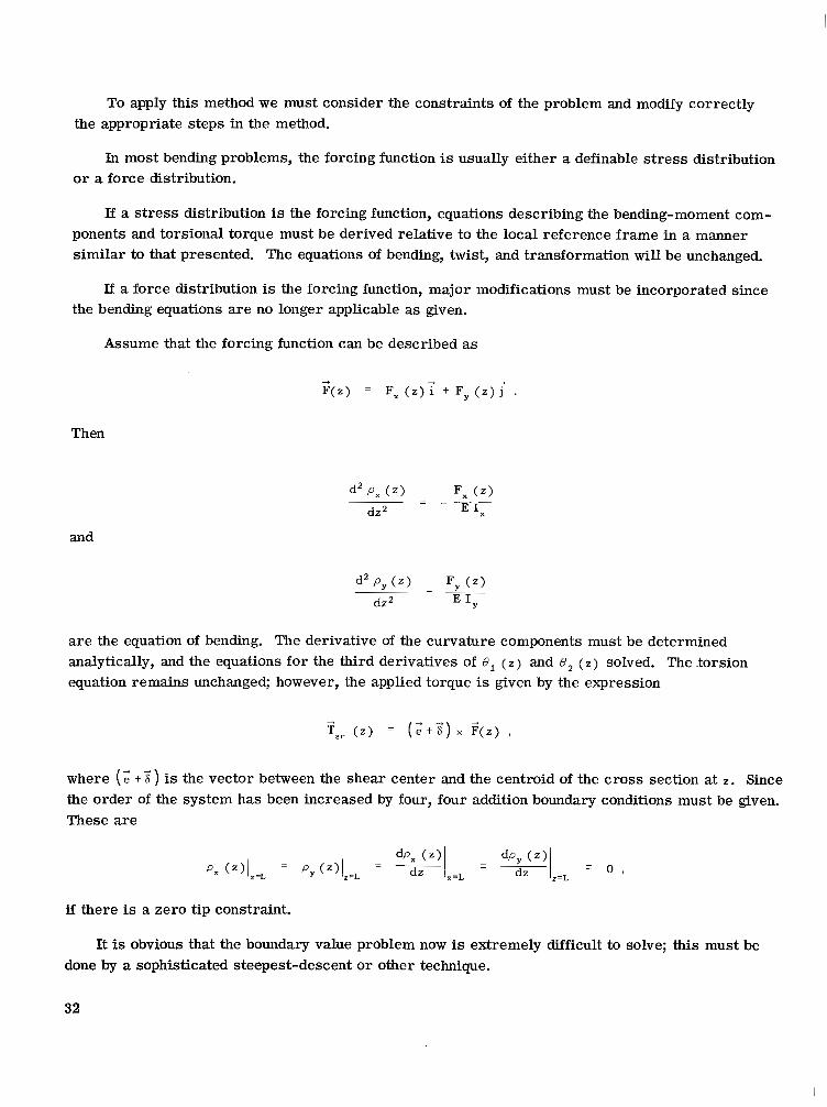
To apply this method we must consider the constraints of the problem and modify correctly the appropriate steps in the method.
In most bending problems, the forcing function is usually either a definable s t ress distribution or a force distribution.
If a s t ress distribution is the forcing function, equations describing the bending-moment com- ponents and torsional torque must be derived relative to the local reference frame in a manner similar to that presented. The equations of bending, twist, and transformation will be unchanged.
If a force distribution is the forcing function, major modifications must be incorporated since the bending equations a re no longer applicable as given.
Assume that the forcing function can be described as
Then
and
are the equation of bending. The derivative of the curvature components must be determined analytically, and the equations for the third derivatives of 8, ( z ) and 8, ( z ) solved. The torsion equation remains unchanged; however, the applied torque is given by the expression
where (: + 2 is the vector between the shear center and the centroid of the cross section at Z . Since the order of the system has been increased by four, four addition boundary conditions must be given. These a re
if there is a zero tip constraint.
It is obvious that the boundary value problem now is extremely difficult to solve; this must be done by a sophisticated steepest-descent or other technique.
32
FIGURES 7 THROUGH 13 APPLIED TORQUES, BENDING AND TORSION, VARIABLE OVERLAP
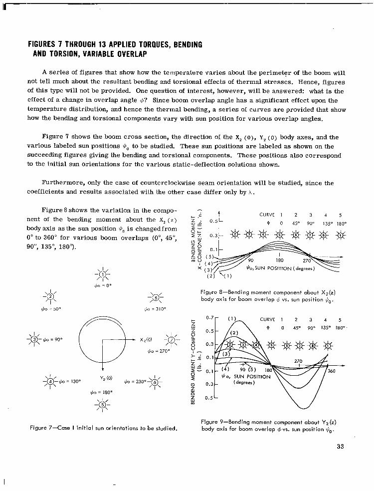
A ser ies of figures that show how the temperature varies about the perimeter of the boom will not tell much about the resultant bending and torsional effects of thermal stresses. Hence, figures of this type will not be provided. One question of interest, however, will be answered: what is the effect of a change in overlap angle $? Since boom overlap angle has a significant effect upon the temperature distribution, and hence the thermal bending, a ser ies of curves are provided that show how the bending and torsional components vary with sun position for various overlap angles.
Figure 7 shows the boom cross section, the direction of the X, (o), Y, (0) body axes, and the various labeled sun positions +o to be studied. These sun positions are labeled as shown on the succeeding figures giving the bending and torsional components. These positions also correspond to the initial sun orientations for the various static-deflection solutions shown.
Furthermore, only the case of counterclockwise seam orientation will be studied, since the coefficients and results associated with the other case differ only by A .
CURVE 1 2 3 4 5 Figure 8 shows the variation in the compo-
'4' 0 45" 90" 135" 180° nent of the bending moment about the X, ( z )
body axis as the sun position $,, is changedfrom 0" to 360" for various boom overlaps (0", 45", 90°, 135", 180").
180
I
' I ' $0 = 0"
-'@L
I
2@); / I
Figure 8-Bending moment component about X ~ ( Z ) body axis for boom overlap q5 vs. sun position $,,.
$0 = 50" 60 = 310'
t
I -'& ' I'
0.5 L
Figure 9-Bending moment component about Y2 (2) body axis for boom overlap +vs. sun position &. Figure 7-Case I in i t ia l sun orientations to be studied.
33

Figure 9 shows the variation in the component of the bending moment about the Y, ( Z ) body axis as the sun position $o is changed from 0" to 360" for various boom overlaps (0", 45", 90°, 135", 180").
changed from 0" tu 360" for various boom overlaps (0", 45", go", 135", 180"). The five curves shown are obtained by plotting EM, ( $o 1 vs. BM, ($bo ) . The various sun positions labeled correspond to 30-degree incremental changes in 3, and are also labeled on the curves.
Figure 10 shows the change in magnitude and direction of the bending moment vector as $o is
BENDING MOMENT Y -COMPO
\ NUMBERS ON CURVES CORRESPOND -
1
ENT (Ib. in. )
t 10
0 . 5
I ~ - L .
BENDING MOMENT X-COMPONENT ( Ib. in.
Figure 10-Variation in bending moment for boom overlap 4 as sun positions change.
34
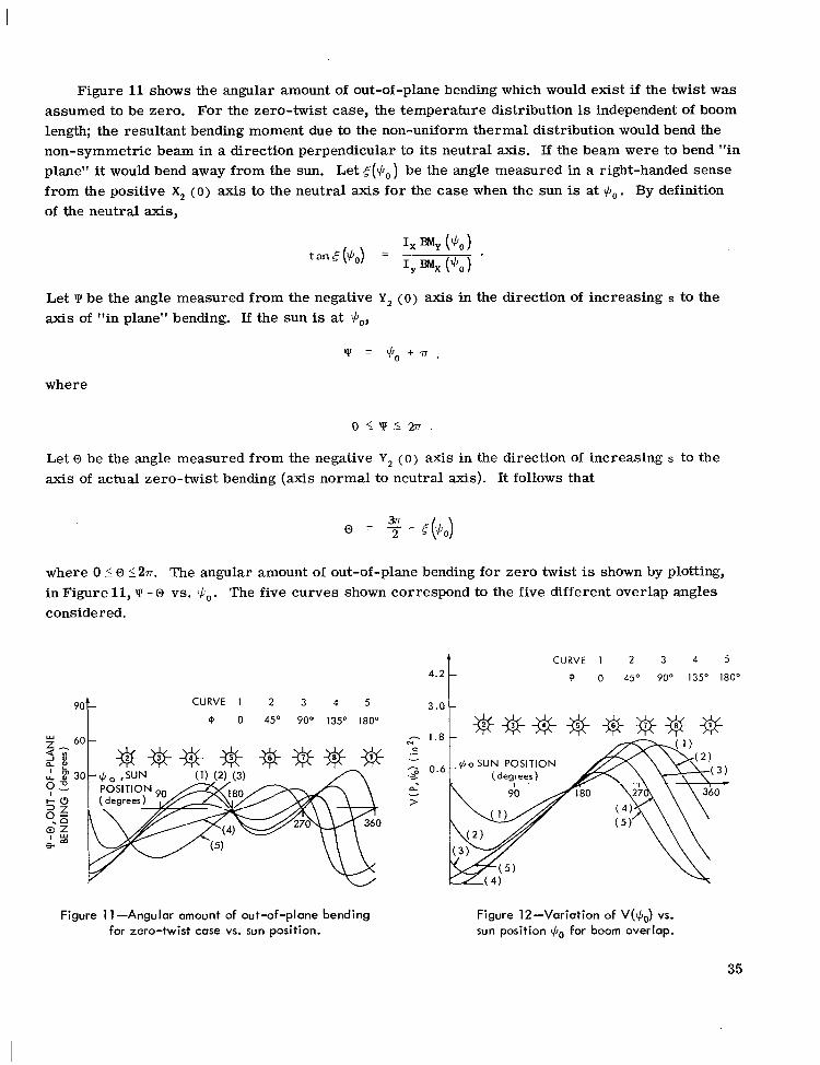
Figure 11 shows the angular amount of out-of-plane bending which would exist if the twist was assumed to be zero. For the zero-twist case, the temperature distribution is independent of boom length; the resultant bending moment due to the non-uniform thermal distribution would bend the non-symmetric beam in a direction perpendicular to its neutral axis. If the beam were to bend "in plane" it would bend away from the sun. Let from the positive X, ( 0 ) axis to the neutral axis for the case when the sun is at $o. By definition of the neutral axis,
be the angle measured in a right-handed sense
Let UI be the angle measured from the negative Y, ( 0 ) axis in the direction of increasing s to the axis of "in plane" bending. If the sun is at $o,
where
Let 0 be the angle measured from the negative Y, ( 0 ) axis in the direction of increasing s to the axis of actual zero-twist bending (axis normal to neutral axis). It follows that
where 0 50 (27~. The angular amount of out-of-plane bending for zero twist is shown by plotting, in Figure 11, considered.
- 0 vs. +o. The five curves shown correspond to the five different overlap angles
4 . 2 1 CURVE 1 2 3 4 5
9 0 45O 90° 135' 180"
3.0 c CURVE 1 2 3 4 5
Figure 1 1 -Angular amount of out-of-plane bending for zero-twist case vs. sun position.
Figure 12-Variation of V(yf~~) vs. sun position $o for boom overlap.
35

Figure 12 shows the variation in the func- CURVE 1 2 3 4 5
@ 0 45" 90" 135" 180" tion V(P, $o
from 0" to 360". It will be recalled that the as the sun position$,, is changed
& # $ $ * * * % & derivative of this function with respect to lon- gitudinal arc length is proportional to the thermal torque under "Thermal Torque." The five curves shown correspond to the five over- lap angles considered.
Figure 13 shows the variation of the derivative of the function V(P, G o ) shown in Figure 12 with respect to $o as sun position
Figure 13-Derivative of the function shown in Figure 12. $o is changed from 0" to 360".
COMMENTS ON FIGURES 7 THROUGH 13
Figures 7 through 13 provide a means of deriving a quantitative estimate of the effects of a change in overlap angle on the thermal bending moment and the thermal torque coefficient. By making use of the data provided on Figures 8,9, o r 10 and the equations
1 EMy XI ( z ) e -__ 2 E I Y z 2
. 1 BMX Y l ( Z ) = - -- 2 E I x z 2 7
a first-order approximation of the deflection associated with the trivial (cp" ( 0 ) = 0) zero-twist solution to the boundary value problem can be obtained.
The non-trivial solution, however, cannot be simplified; and the data provided on these figures yield little information as to the actual thermal equilibrium shapes. Only after examination of a particular case can we gain some insight as to how to predict them, see below.
SOLUTION TO A PARTICULAR PROBLEM
The following is a list of the magnitudes of the geometrical and physical constants used to obtain a solution to the derived equations. The magnitudes stated characterize a silver-plated DeHavilland boom of the type now being considered for use as a Gravity Gradient boom on the ATS and RAE satellites.
J, = Solar radiation intensity = 3.065 BTU/(hr in2)
as = Absorbtivity = 0.13
P = Perimeter of cross section = 2"
36
E = Emissivity = 0.035
K = Thermal conductivity = 6.0 BTU/(in F" hr)
t = Thickness of cross section = 0.002"
ec = Thermal expansion coefficient = 0.104 X 1 0 - 4
To = Absolute ambient temperature = 535 R"
E = Young's Modulus = 19 X IO6 lb/in2
= Radiation coefficient = 0.121 X BTU/(hr in2)
4 = Boom overlap angle = 100 degrees
G = Shear Modulus = 6 X l o 6 lb/in2.
Before a detailed discussion of each figure showing the results of the computer solution is initiated, a brief mention of the limitations and implications of these results will be given.
1. It is felt that the equations defining the temperature distribution represent a worst-case estimate. That is, the actual temperature gradients will be smaller than those used in this analysis because
a. internal radiation has been neglected
b. zero contact in overlap region is assumed
c. diameter changes are assumed negligible
d. the boom is assumed homogenous
e. actual boom oscillation in space will have an averaging effect.
2. The boom is assumed to be perfectly clamped at the root. This condition in actual practice is impossible to obtain. It will be shown that, for a perfectly clamped boom under a given length and deflected by the predefined thermal stresses, only the trivial solution to the torsional part of the boundary value problem exists. This implies that short booms will be bent but not twisted by thermal stresses. Any twist, observed experimentally on short booms, is indicative of the non- perfect clamping and non-uniform physical characteristics of the boom itself.
3. This analysis cannot and is not intended to give the exact deflected shape of an actual boom. However, it can and will bring to light many properties of thermal bending not generally known. It will be shown that some very unusual results can be obtained; for instance, part of the boom could actually corkscrew and bend back at the sun. Such cases are very special and involve simplifying assumptions; they are examples of what can happen rather than what will happen in flight.
37
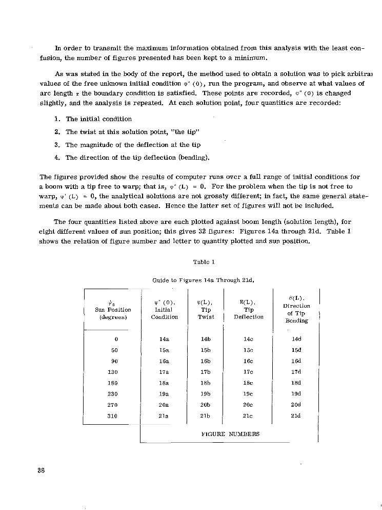
In order to transmit the maximum information obtained from this analysis with the least con- fusion, the number of figures presented has been kept to a minimum.
As was stated in the body of the report, the method used to obtain a solution was to pick arbitral values of the free unknown initial condition q'' (0) , run the program, and observe at what values of arc length z the boundary condition is satisfied. These points a r e recorded, V" ( 0 ) is changed slightly, and the analysis is repeated. At each solution point, four quantities a re recorded:
1. The initial condition
2. The twist at this solution point, "the tip"
3. The magnitude of the deflection at the tip
4. The direction of the tip deflection (bending).
The figures provided show the results of computer runs over a full range of initial conditions for a boom with a tip free to warp; that is, m " (L) = 0. For the problem when the tip is not free to warp, cp' (L) = 0, the analytical solutions a r e not grossly different; in fact, the same general state- ments can be made about both cases. Hence the latter set of figures will not be included.
The four quantities listed above are each plotted against boom length (solution length), for eight different values of sun position; this gives 32 figures: Figures 14a through 21d. Table 1 shows the relation of figure number and letter to quantity plotted and sun position.
Table 1
Guide to Figures 14a Through 21d.
I $0 Sun Position
(degrees)
0
50
90
13 0
180
~
( P I ! ( O ) , Initial
Condition
14a
15a
16a
17a
18a
19a
2 Oa
2 l a
W) 7
Tip Twist
14b
15b
16b
17b
18b
19b
20b
21b ~~
W ) 9
Tip Deflection
14c
15c
16c
17c
18c
19c
2 oc
21c
FIGURE NUMBERS
9
Direction of Tip
Bending
14d
15d
16d
17d
18d
19d
2 Od
2 Id
38

0.0003 Z o_ E 0.0002 k
Z
-I 0.0001 9 t z h . a
8
0 v
9
0.0001
751
- n L, SOLUTION LENGTH( feet)
Figure 14a-Initial condition rp" (0) vs. solution length L for$Jo = 0.
L, SOLUTION LENGTH (feet)
Figure 14c-Tip deflection R(L) vs. solution length L for $Jo = 0.
i- I I I )
50 100 150 L, SOLUTION LENGTH (feet)
Figure 14b-Tip twist rp (L) vs. solution length L for $Jo = 0.
a
-IN PLANE
I I I _ 50 1 00 150 - L, SOLUTION LENGTH (feet)
Figure 14d-Direction of t ip bending e (L) vs. solution length L for $ J ~ = 0'.
39
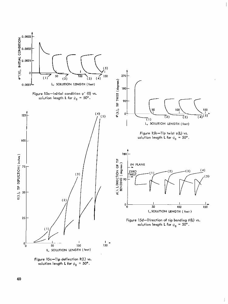
0.0001 L L, SOLUTION LENGTH (feet)
Figure 15a-Initial condition q" (0) vs. solution length L for $Jo = 50".
L, SOLUTION LENGTH ( feet)
270 t h
4 6 180 c/ v
L, SOLUTION LENGTH (feet) I Figure 15b-Tip t w i s t q(L) vs.
solution length L for $Jo = 50".
1 8 0 1
I I I * 0 50 100 150
L, SOLUTION LENGTH ( feet )
Figure 15d-Direction of t ip bending B(L) vs. solution length L for $Jo = 50'.
Figure 1%-Tip deflection R(L) vs. solution length L for $ J ~ = 50".
40
1 z 2 0.0002 D z g 0.0001 ":
z c
=- O l
A
0 - 0.0001
L,SOLUTlON LENGTH (feet)
125
100
- 0
= 75
0 8
r C
Z
I-
2 U Y
n 5 7 50 h
2
oz v
25
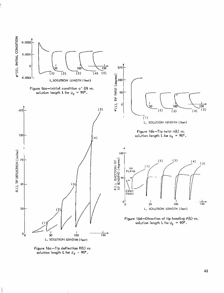
Figure 160-Initial condition v'' (0) VS.
solution length L for $o = 90".
1
180
L, SOLUTION LENGTH (feet.)
1-
- I -
C /
( 1 ) L, SOLUTION LENGTH (feet)
Figure 16b-Tip twist q(L) vs. solution length L for $o = 90".
ZERO TWIST
I 50
L, SOLUTION LENGTH (feet)
Figure 16d-Direction of tip bending B(L) vs. solution length L for $o = 90".
Figure 16c-Tip deflection R(L) vs. solution length L for $o = 90".
41
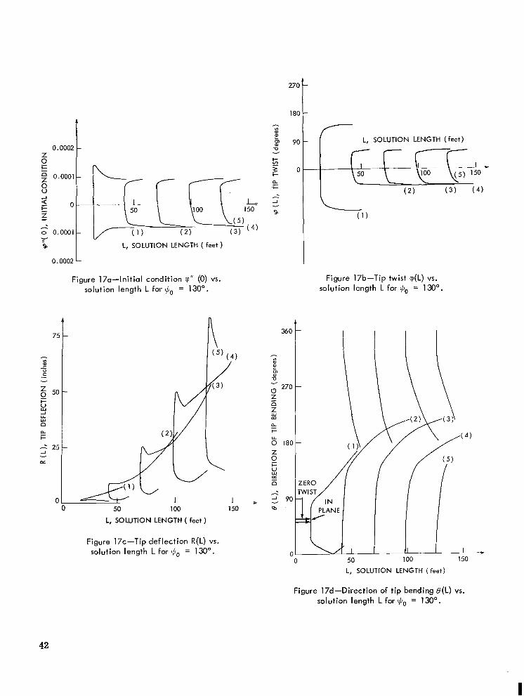
0.0002 z t 9 2 0.0001
s -I
9 0
z c - 0 0.0001
9 Y
0.0002
L, SOLUTION LENGTH ( feet)
Figure 17a-Initial condition v'' (0) VS.
solution length L for Go = 130'.
75
8 L 0
.- v
50 2 8 I-
-I U W
D % I- -
L, SOLUTION LENGTH ( feet )
I (5) ( 4
270
180
P 90
-0
I-
v
C"
5 E o '+ -I v
9
360
- w al E
(3 270
m -0 v
z 5 D
m
5
8 180 Z
I-
9 L
L, SOLUTION LENGTH ( feet) (-
Figure 17b-Tip t w i s t q(L) vs. solution length L for Go = 130'.
I I I I
Figure 17c-Tip deflection R(L) vs. solution length L for Go = 130'.
L, SOLUTION LENGTH (feet)
Figure 17d-Direction of t ip bending B(L) vs. solution length L for Go = 130'.
42
I

t
I_
t 0.0002 Z 0 L
L, SOLUTION LENGTH (feet) 8 t: z 0 o.Ooo1
9 Y
0.0002
Figure 18a-Initial condition cp" (0) vs. solution length L for $Jo = 180'.
0
L, SOLUTION LENGTH ( feet)
Figure 18c-Tip deflection R(L) vs. solution length L for $Jo = 180'.
360
;v" t m
3
$ 270 n - 5 m
e
0 Z 180
r u-
0 v, 5 n
I-
-I
m v
90
C
7 L, SOLUTION LENGTH ( feet)
I
i Figure 18b-Tip t w i s t cp(L) vs.
solution length L for $J0 = 180'
IN ,PLANE
1 IN 50 100
PLANE L, SOLUTION LENGTH (feet)
Figure 18d-Direction of t ip bending B(L) vs. solution length L for $Jo = 180°.
43

I I I
h
8 9 0 .
-0 v
I I 1111111111 1 1 1 I 1 I1 I I I I I I I I,,
0.0002 1
0.0003
Figure 19a-Initial condition y'' (0) vs. solution length L for $J0 = 230".
L, SOLUTION LENGTH ( feet )
1 , 150
Figure 19c-Tip deflection R(L) vs. solution length L for $Jo = 230'.
A
180
- L, SOLUTION LENGTH (feet)
Figure 19b-Tip twist cp(L) vs. solution length L for $Jo = 230".
ZERO TWIST
0 1 . 0 50
L , SOLUTION LENGTH ( feet )
1 I L 150
Figure 19d-Direction of t ip bending B(L) vs. solution length L for $,, = 230".
44
0.0002
Z 0
0.0001 Z
-I C 9 I= z 2 0.0001
8
0 v
0 0.0002
0.0003
L, SOLUTION LENGTH ( feet)
50 100 150
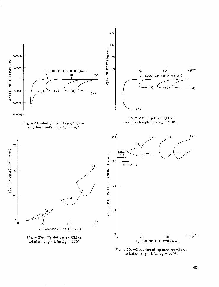
Figure 200-Initial condition 9" (0) vs. solution length L for +o = 270".
( 4 )
I 50 100
L, SOLUTION LENGTH ( feet)
Figure 20c-Tip deflection R(L) vs. solution length L for $Jo = 270".
2 150
I I -2 50 100 150 L, SOLUTION LENGTH ( feet)
Figure 20b-Tip t w i s t v(L) vs. solution length L for +o = 270O.
- - IN PLANE
I I L 0 50 100 150
L, SOLUTION LENGTH ( feet)
Figure 20d-Direction of tip bending B(L) vs. solution length L for $J0 = 270".
45

L
0 z
---I . . -1, 8
100 150 L, SOLUTION LENGTH (feet) t= z
t 2 0.0001 0 v
9 0.0002
Figure 21a-Initial condition V ” (0) vs. solution length L for $o = 310O.
n
50 I00 L, SOLUTION LENGTH (feet)
Figure 2lc-Tip deflection R(L) vs. solution length L for = 310O.
L 150
Figure 21d-Direction of t ip bending B(L) vs. solution length L for $o = 310’.
1 -- . 1- ~.
L, SOLUTION LENGTH (feet) 50 100 150
Figure 21 b-Tip t w i s t cp(L) vs. solution length L for $o = 310O.
I 100 L
150 L, SOLUTION LENGTH (feet)
46
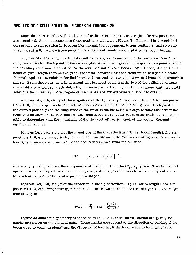
RESULTS OF DIGITAL SOLUTION, FIGURES 14 THROUGH 25
Since different results will be obtained for different sun positions, eight different positions a re examined; these correspond to those positions labeled on Figure 7. Figures 14a through 14d correspond to sun position 1, Figures 15a through 15d correspond to sun position 2, and so on up to sun position 8. For each sun position four different quantities a re plotted vs. boom length.
Figures 14a, 15a, etc., plot initial condition rp" (0) vs. boom length L for such positions 1, 2, etc., respectively. Each point of the curves plotted on these figures corresponds to a point at which the boundary condition is satisfied for the assumed initial conditions rp" ( 0 ) . Hence, i f a particular boom of given length is to be analyzed, the initial condition or conditions which will yield a static- thermal-equilibrium solution for that boom and sun position can be determined from the appropriate figure. From these curves it is apparent that for most boom lengths two of the initial conditions that yield a solution a re easily definable; however, all of the other initial conditions that also yield solutions lie in the asympotic region of the curves and are extremely difficult to obtain.
Figures 14b, 15b, etc.,plot the magnitude of the tip twist V(L) vs. boom length L for sun posi- tions 1, 2, etc., respectively for each solution shown in the "a" series of figures. Each point of the curves plotted gives the magnitude of the twist at the boom tip but says nothing about what the twist will be between the root and the tip. Hence, for a particular boom being analyzed i t is pos- sible to determine what the magnitude of the tip twist will be for each of the booms' thermal- equilibrium shape s.
Figures 14c, 15c, etc., plot the magnitude of the tip deflection R(L) vs. boom length^ for sun positions 1, 2, etc., respectively, for each solution shown in the "a" ser ies of figures. The magni- tude R(L) is measured in inertial space and is determined from the equation
where X, (L) and Y, (L) are the components of the boom tip in the ( x , , Y1) plane, fixed in inertial space. Hence, for a particular boom being analyzed it is possible to determine the tip deflection for each of the booms' thermal-equilibrium shapes.
Figures 14d, 15d, etc., plot the direction of the tip deflection B(L) vs. boom length L for sun positions 1, 2, etc., respectively, for each solution shown in the "a" series of figures. The magni- tude of B(L) is
Figure 22 shows the geometry of these relations. In each of the "d" series of figures, two marks are shown on the vertical axis. These marks correspond to the direction of bending if the boom were to bend "in plane'' and the direction of bending if the boom were to bend with "zero
47
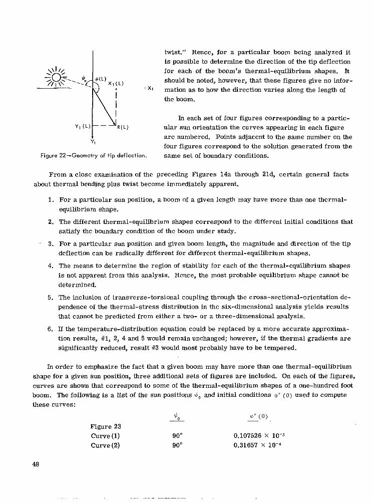
twist." Hence, for a particular boom being analyzed it is possible to determine the direction of the tip deflection for each of the boom's thermal-equilibrium shapes. It should be noted, however, that these figures give no infor- mation as to how the direction varies along the length of the boom.
Xl(L) $CJ-. 115 -. $0 i(L)
In each set of four figures corresponding to a partic- I R(L) ular sun orientation the curves appearing in each figure
are numbered. Points adjacent to the same number on the four figures correspond to the solution generated from the same set of boundary conditions.
Yl(L) p --
Yl
Figure 22-Geometry of t ip deflection.
From a close examination of the preceding Figures 14a through 21d, certain general facts about thermal bending plus twist become immediately apparent.
1. For a particular sun position, a boom of a given length may have more than one thermal- equilibrium shape.
2. The different thermal-equilibrium shapes correspond to the different initial conditions that satisfy the boundary condition of the boom under study.
3. For a particular sun position and given boom length, the magnitude and direction of the tip deflection can be radically different for different thermal-equilibrium shapes.
4. The means to determine the region of stability for each of the thermal-equilibrium shapes is not apparent from this analysis. Hence, the most probable equilibrium shape cannot be determined.
5. The inclusion of transverse-torsional coupling through the cross-sectional-orientation de- pendence of the thermal-stress distribution in the six-dimensional analysis yields results that cannot be predicted from either a two- or a three-dimensional analysis.
6. If the temperature-distribution equation could be replaced by a more accurate approxima- tion results, #1, 2, 4 and 5 would remain unchanged; however, if the thermal gradients are significantly reduced, result #3 would most probably have to be tempered.
In order to emphasize the fact that a given boom may have more than one thermal-equilibrium shape for a given sun position, three additional sets of figures are included. On each of the figures, curves are shown that correspond to some of the thermal-equilibrium shapes of a one-hundred foot boom. The following is a list of the sun positions 4,, and initial conditions q" ( 0 ) used to compute these curves:
3, V I J ( 0 )
Figure 23 Curve (1) 90" 0.107526 X
Curve (2) 90" 0.31657 X
48
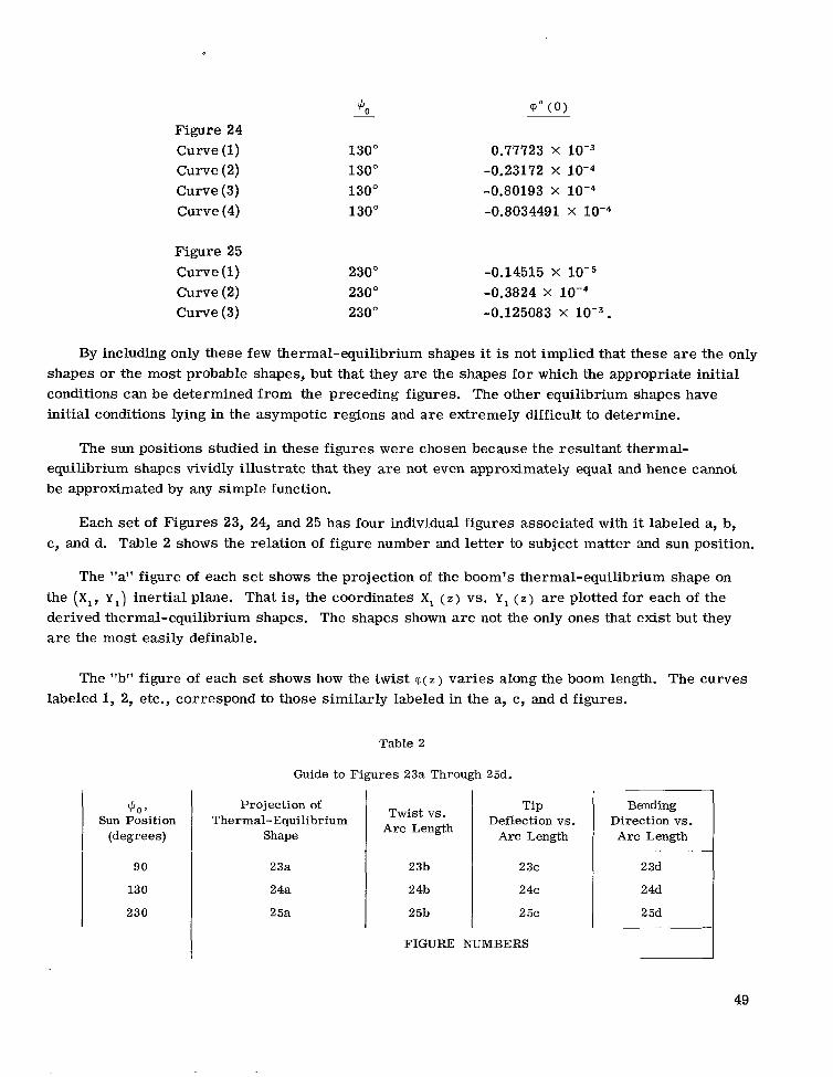
Figure 24 Curve (1) Curve (2) Curve (3) Curve (4)
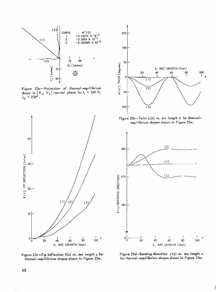
Figure 25 Curve (1) Curve (2) Curve (3)
5 cp" (0)
130" 0.77723 X
130" -0.23172 X
130" -0.80193 X
130" -0.8034491 x
230" 230" 230"
-0.14515 X
-0.3824 X
-0.125083 X
By including only these few thermal-equilibrium shapes it is not implied that these are the only shapes or the most probable shapes, but that they are the shapes for which the appropriate initial conditions can be determined from the preceding figures. The other equilibrium shapes have initial conditions lying in the asympotic regions and are extremely difficult to determine.
The sun positions studied in these figures were chosen because the resultant thermal- equilibrium shapes vividly illustrate that they are not even approximately equal and hence cannot be approximated by any simple function.
Each set of Figures 23, 24, and 25 has four individual figures associated with it labeled a, by c , and d. Table 2 shows the relation of figure number and letter to subject matter and sun position.
The "a" figure of each se t shows the projection of the boom's thermal-equilibrium shape on the (XI, yl) inertial plane. That is, the coordinates XI ( 2 ) vs. Y , ( 2 ) are plotted for each of the derived thermal-equilibrium shapes. The shapes shown are not the only ones that exist but they a re the most easily definable.
The "b" figure of each set shows how the twist T ( Z ) varies along the boom length. The curves labeled 1, 2, etc., correspond to those similarly labeled in the a, cy and d figures.
Table 2
Guide to Figures 23a Through 25d.
$0 Sun Position
(degrees)
90
130
230
Projection of Thermal-Equilibrium
Shape
23a
24a
2 5a
Tip Deflection vs.
Arc Length
Twist vs. Arc Length
23b
24b
25b
23c
24c
2 5c
FIGURE NUMBERS
Bending Direction vs. Arc Length
2 3d
24d
2 5d
49

I CURVE S " ( 0 )
1 0.107526X10⁻³ 2 0.3169X
$+- XI( inches)
Figure 23a-Projection of thermal-equilibrium shape in (X,, Y,) inertial plane for L = 100 ft, qJo = 90".
40
h ", 0 L
.- 30
Z 0
v
- I-
M -I LL w D tx r 20 - N
a! v
10
C
50
I
20 40 60 80 100 I, ARC LENGTH ( feet )
t
180
I z, ARC LENGTH(feet)
180 90L Figure 23b-Twist ~ ( z ) vs. arc length z for thermal-
equilibrium shapes shown in Figure 23a.
Z 0 Y
z t,
I-
E
(3
D
D
m
h
N d
1 I 1 0 20 40 60 80 100 0
z , ARC LENGTH (feet)
Figure 23d-Bending direction B(z) vs. arc length z for thermal-equilibrium shapes shown in Figure 23a.
Figure 23c-Tip deflection R(z) vs. arc length z for thermal-equilibrium shapes shown in Figure 23a.
I

CURVE Q "(0) 1 - 0 . m 2 3 x 1 0 - ~ 2 -0.23172 X 3 -0.80193 X 4 -0.803449 X
0 0
1. 20 30
I I 1 - 60 80 100
I \ I 20 40
I / X I (inches)
Figure 24a-Projection of thermal-equilibrium shape in (X I , Y , ) inertial plane for L = 100 ft, +,, = 130".
3
4c
- ", W L 0 C .- 2 3( P u, n 0
2 2c
c
2 LL Y
I-
N
cd -
1c
C 20 40 60 80 1 00
z , ARC LENGTH (feet)
U v 90t n
2 , ARC LENGTH (feet)
1 8 0 1
Figure 24b-Twist ~ ( z ) vs. arc length z for thermal- equilibrium shapes shown in Figure 24a.
360
- 270 0 E m U v
Z 9 Y I-
c* - 180
(3 Z n - t m
N
m d
90
\ Cp"(0) ,(2)! C U Y E 2 -0.14515 -0.3824 X X
3 -0.125083 X
h L$ lot Xl(;es) v
>- 20
Figure 250-Projection of thermal-equi I ibrium shape in (X,, Y,) inertial plane for L = 100 ft, $ J ~ = 230".
z, ARC LENGTH ( feet)
Figure 25c-Tip deflection R(z) vs. arc length z for thermal-equilibrium shapes shown in Figure 25a.
180
2701
m U v
W ( 3 )
180 t
Z, ARC LENGTH ( feet)
40 60 80 100 I C
1
Figure 25b-Twist ~ ( z ) vs. arc length z for thermal- equilibrium shapes shown in Figure 250.
360
z 270 0 E !-
5 n (3 z n z,
180 N
WJ
v
0 1 % 1 I I 20 40 60 80
Z, ARC LENGTH ( feet)
100 I
Figure 25d-Bending direction O(z) vs. arc length z for thermal-equilibrium shapes shown in Figure 250.
52
The "c" figure of each set shows how the magnitude of the deflection increases along the boom length. The magnitude R ( z ) is derived from the equation
R ( z ) = [X1 ( z ) ~ +Yl ( z ) ~ ] ' "
The "d" figure of each set shows how the direction of bending changes along the boom length. The quantity B ( z ) which is plotted is defined by the equation
where 0 ~ B ( z ) 2 2 ~ .
Examination of Figures 23, 24, and 25 discloses certain facts about thermal bending:
1. For this particular boom and temperature distribution, the thermal-equilibrium shapes a re grossly different from each other.
2. Each thermal-equilibrium shape corresponds to a distinct pattern of twist.
3. The thermal-equilibrium shapes that correspond to twist patterns of low magnitude a re nearly planar in bending.
4. For the cases studied it is apparent that the direction of bending has its most significant change in the interval of length along which the twist is going through its first half cycle.
5. The large out-of-plane bending, evident for some thermal-equilibrium shapes, is a result of the coupling between bending and torsion. This coupling over the length is a result of the fact that the direction of bending at any point depends not only on the direction of the thermal-bending-moment vector at the point in question but also on the shape of the boom up to this point. .
6. The direction of deflection depends on more than just the local stress distribution and position. This can be seen from an analysis of the equations of bending. Since the order of this system of equations is eight rather than six, it follows that the six coordinate mag- nitudes at a point and the forcing function are not enough to define the coordinate magni- tudes at the point an infinitesimal distance away. TO determine these magnitudes, two additional conditions must be given which characterize the boom's shake between the root and the point in question.
7. The deflected shape of the boom up to a particular point affects the deflected shape after that point, and the thermal s t resses can induce a significant amount of out-of-plane bending. These two effects can be combined through the transverse torsional coupling. This may bring about much more out-of-plane bending than would be expected from considering only the resultant bending-moment variation with sun position as shown in Figure 10 or the results shown in Figure 11.
53
I

ANALYTIC SOLUTION TO TORSION EQUATION
The torsion equation as previously derived; i.e.,
C E e ~ aV(z ) dY( z ) cp"' ( 2 ) - [q + A
is highly nonlinear and coupled with the bending equation for large-angle twist. If, however, one restricts the discussion to small-angle twist and bending,
and the torsion equation can be written in the form
where A 2 , B, and D a re constants whose magnitude can be determined from the coefficient of the derived torsion equation given above and from a parabolic representation of av(~)/aY(z) about the initial sun orientation $o (see Figure 13).
When the above equation is integrated once, it can be put in the form of a general elliptic equation; that is,
where cp" ( 0 ) is the constant of integration equal to cp" ( Z ) I = = ~ when c p ( ~ ) I , = ~ = 0.
In Reference 5 it is shown that by an additional integration this equation can be put in the form
B D cp ' (2)'
= cp' (0) ' + 2cp" (O)cp(z) + A' cp2 (2) + 5 cp3 ( z ) + 5 cp4 ( z )
and that a transformation
Lf = 5(cp)
can be found which further reduces the equation to the form
(g)2 = ( 1 - 5 2 ) ( 1 - m 2 5 2 ) .
54

This equation is well known and the solution to it is given by
where sn( Z , m ) is the elliptic sine of Jacobi. Inverting the transformation 5 = 5((p) gives the equa- tion defining cp(z); it is given in terms of the Jacobi elliptic functions.
Function c p ( ~ ) can be computed for any particular case; but a general solution cannot be obtained, since the solution requires the determination of the roots of a quartic equation and the magnitude of 9'' (0). The quantity cp" ( 0 ) is a function of the boundary condition and must be obtained from the solution of a transcendental equation written in terms of the Jacobi elliptic functions.
Since a general solution to the elliptic equation cannot be found, the more restrictive assump- tion that
where
must be made. It follows from the parametric magnitudes listed on page 36 and the equations given on page 16 that
C 0.032 lb i n 2
C, = 1413.7 l b in4
t E e c r = 0.0985 lb ,
and hence
The actual magnitude of av($,)/aY(z) can be obtained approximately from the curves provided in Figure 13. From the shape of these curves it is apparent that the above assumption is reasonable in the interval
SO" < Go 200" .
Outside of this interval the assumption is valid only for very small cp(z).
55
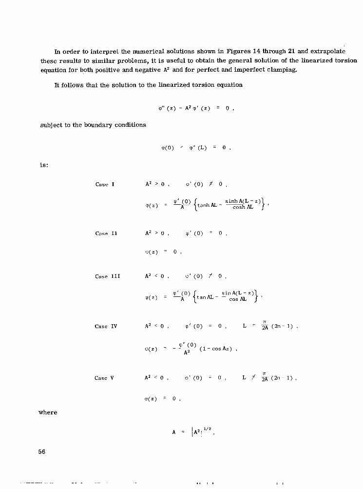
In order to interpret the numerical solutions shown in Figures 14 through 21 and extrapolate these results to similar problems, it is useful to obtain the general solution of the linearized torsion equation for both positive and negative AZ and for perfect and imperfect clamping.
It follows that the solution to the linearized torsion equation
subject to the boundary conditions
m(0) = q" (L) = 0 ,
is:
Case I
Case I1
cp(z) - - - "io) { t a n h a -
A 2 > 0 , Cp'(0) = 0 1
q ( z ) = 0 ,
Case IV
Case V
where
A = lA211'2.
56

A comparison of these equations with the solution shown in Figures 14 through 21 yields a number of results which further explain the observed phenomena. These can be summarized as follows :
1. For the particular case of perfect clamping, cp' (0)
solution exists only if A2 is negative and the boom length L
= 0, a non-trivial linear small-angle is given by
Tr L = ~ ( 2 " - 1 ) .
In the sun interval
50" < $,, < 200" .
Figure 13 shows that
and hence
g.032-0.0985 ~ 1 . 5 A ' I 1413.7
= 0.009049 in-' ,
or, for n = 1,
Figures 16 through 18 correspond to sun orientations Yo within the interval
60" < $, < 200" .
In these figures the numerical solution shows that only booms of specific lengths will have non- trivial small-angle solutions and that these solution lengths can be approximated by the equation
L = ( 2 n - 1 ) x 14.5 ft n = 1, 2, . * -
as predicted by the analytic solution Case IV and Case V.
57
I
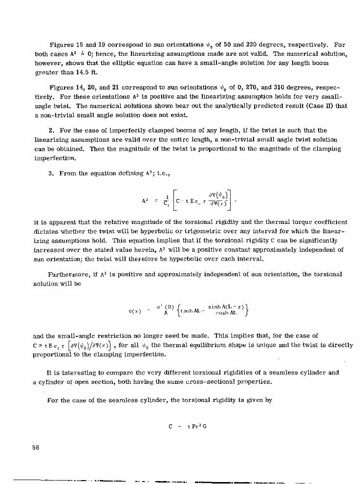
Figures 15 and 19 correspond to sun orientations 3, of 50 and 230 degrees, respectively. For both cases A2 0; hence, the linearizing assumptions made a re not valid. The numerical solution, however, shows that the elliptic equation can have a small-angle solution for any length boom greater than 14.5 ft.
Figures 14, 20, and 21 correspond to sun orientations 3, of 0, 270, and 310 degrees, respec- tively. For these orientations A2 is positive and the linearizing assumption holds for very small- angle twist. The numerical solutions shown bear out the analytically predicted result (Case II) that a non-trivial small angle solution does not exist.
2. For the case of imperfectly clamped booms of any length, i f the twist is such that the linearizing assumptions are valid over the entire length, a non-trivial small angle twist solution can be obtained. Then the magnitude of the twist is proportional to the magnitude of the clamping imperfection.
3. From the equation defining A2; Le.,
it is apparent that the relative magnitude of the torsional rigidity and the thermal torque coefficient dictates whether the twist will be hyperbolic or trigometric over any interval for which the linear- izing assumptions hold. This equation implies that if the torsional rigidity C can be significantly increased over the stated value herein, AZ will be a positive constant approximately independent of sun orientation; the twist will therefore be hyperbolic over each interval.
Furthermore, if A2 is positive and approximately independent of sun orientation, the torsional solution will be
and the small-angle restriction no longer need be made. This implies C t E ec r [aV($,)/JY( z)] , for all +, the thermal equilibrium shape is proportional to the clamping imperfection.
that, for the case of unique and the twist is directly
It is interesting to compare the very different torsional rigidities of a seamless cylinder and a cylinder of open section, both having the same cross-sectional properties.
For the case of the seamless cylinder, the torsional rigidity is given by
58
and, as previously stated, the torsional rigidity of the cylinder of open section is
1 c = 3 t 3 F G
Thus, the torsional rigidity of a seamless cylinder is 3 r 2 / t times greater than that of a cylinder of open section, which for the constants of this problem is equal to 0.3675 X lo5.
Hence, it is not unreasonable to expect that a Gravity Gradient boom could be designed that would have an effective torsional rigidity significantly larger than the coefficient of the thermal torque and hence have a unique thermal-equilibrium shape for every sun orientation.
CONCLUSIONS
The most important facts shown in this analysis of a particular type of Gravity Gradient boom may be summarized as follows:
1. A method has been developed by which the non-planar thermal bending plus twist of very long thin-walled members of open section may be studied.
2. The thermal-equilibrium shape of a Gravity Gradient boom in a solar thermal field is not unique.
3. The various possible thermal-equilibrium shapes may radically differ from each other in magnitude, direction, and shape.
4. Transverse-torsional coupling is a very significant effect in booms having high thermal gradients and low torsional rigidity.
5. A means of performing a stability analysis on the various thermal-equilibrium shapes is not apparent from this analysis.
6. A unique function that can be used in the dynamic analysis of a Gravity Gradient satellite to approximate the thermal bending of the booms does not exist for the particular case studied.
7. Thermally induced twist cannot be assumed to have small magnitude.
8. The thermal-equilibrium shapes that have twist of low magnitudes associated with them tend to bend in a nearly predictable direction.
9. For every sun orientation studied herein the torsional rigidity of 0.032 lb in2 is large enough to prevent booms of length less than 14.5 f t from assuming more than one thermal- equilibrium shape. For longer length booms, however, more than one thermal-equilibrium shape can satisfy the boundary conditions of the problem.
10. The direction of deflection of any point along the booms' length depends not only on the local conditions (that is, coordinate magnitude and stress distribution) but also on the de- flected shape between the root and the point in question.
,
59

11.
12.
It follows from conclusion 10 that the maximum amount of out-of-plane bending cannot be predicted from a simple study of Figure 11 which plots zero-twist out-of-plane bending vs. sun position.
If the torsional rigidity can be significantly increased above the thermal torque coefficient, the number of thermal-equilibrium shapes will be reduced to one unique thermal-equilibrium shape.
ACKNOWLEDGMENTS
The author gratefully acknowledges the assistance of Mr. Benjamin Zimmerman, Head of the Analytical Studies Section, for the support he provided throughout the development of this report and Miss Kathryn Dohm for the typing of the original manuscript and its succeeding revisions. /
Goddard Space Flight Center National Aeronautics and Space Administration
Greenbelt, Maryland, April 5, 1967 630-12-02-01-51
REFERENCES
1. Timoshenko, S., "Strength of Materials Part II," Princeton, N. J.: Van Nostrand, 1956.
2. Timoshenko, S., llTheory of Bending, Torsion, and Buckling of Thin Walled Members of Open Section," Journal of the Franklin Institute, 239(3, 4, 5), 1945.
3. Boley, B. A., and Weiner, J. H., "Theory of Thermal Stresses," New York: John Wiley, 1960.
4. Southwell, R. V., "An Introduction to the Theory of Elasticity for Engineers and Physicists," London: Oxford University Press, 1941.
5. Davis, H. T., "Introduction to Nonlinear Differential and Integral Equations," New York: Dover Publications, 1962.
60 NXsA-Langley, 1961 - 19
“The aeronautical and space activities of the United States shall be conducted so as to contribute . . . to the expansion of buman Rnowl- edge of phenomena in the atmosphere and space. The Administration sball provide for the widest practicable and appropriate dissemination of information concerning its actiuities and the results tbereof.”
-NATIONAL &RONAUTKS AND SPACE ACT OF I958
NASA SCIENTIFIC AND TECHNICAL PUBLICATIONS
TECHNICAL REPORTS: Scientific and technical information considered important, complete, and a lasting contribution to existing knowledge.
TECHNICAL NOTES: Information less broad in scope but nevertheless of importance as a contribution to existing knowledge.
TECHNICAL MEMORANDUMS: Information receiving limited distribu- tion because of preliminary data, security classification, or other reasons.
CONTRACTOR REPORTS: Scientific and technical information generated under a NASA contract or grant and considered an important contribution to existing knowledge.
TECHNICAL TRANSLATIONS: Information published in a foreign language considered to merit NASA distribution in English.
SPECIAL PUBLICATIONS: Information derived from or of value to NASA activities. Publications include conference proceedings, monographs, data compilations, handbooks, sourcebooks, and special bibliographies.
TECHNOLOGY UTILIZATION PUBLICATIONS: Information on tech- nology used by NASA that may be of particular interest in commercial and other non-aerospace applications. Publications include Tech Briefs, Technology Utilization Reports and Notes, and Technology Surveys.
h t a i l s on the availability of these publications may be obtained from:
SCIENTIFIC AND TECHNICAL INFORMATION DIVISION
N AT1 0 N A L AE R 0 N A UTI CS A N D SPACE A DM I N I STR AT1 0 N
Washington, D.C. PO546