Embed Size (px)
Citation preview

NASA Technical Memorandum 4770
Thermal and Mechanical Buckling Analysis of Hypersonic Aircraft Hat-Stiffened Panels with Varying Face Sheet Geometry and Fiber Orientation
December 1996
William L. Ko

NASA Technical Memorandum 4770
National Aeronautics and Space Administration
Office of Management
Scientific and Technical Information Program
1996
William L. Ko
Dryden Flight Research CenterEdwards, California
Thermal and Mechanical Buckling Analysis of Hypersonic Aircraft Hat-Stiffened Panels with Varying Face Sheet Geometry and Fiber Orientation

CONTENTS
Page
ABSTRACT . . . . . . . . . . . . . . . . . . . . . . . . . . . . . . . . . . . . . . . . . . . . . . . . . . . . . . . . . . . . . . . . . . . . . . . 1
NOMENCLATURE . . . . . . . . . . . . . . . . . . . . . . . . . . . . . . . . . . . . . . . . . . . . . . . . . . . . . . . . . . . . . . . . . 1
INTRODUCTION . . . . . . . . . . . . . . . . . . . . . . . . . . . . . . . . . . . . . . . . . . . . . . . . . . . . . . . . . . . . . . . . . . 3
DESCRIPTION OF PROBLEM. . . . . . . . . . . . . . . . . . . . . . . . . . . . . . . . . . . . . . . . . . . . . . . . . . . . . . . . 3
FINITE-ELEMENT MODELING . . . . . . . . . . . . . . . . . . . . . . . . . . . . . . . . . . . . . . . . . . . . . . . . . . . . . . 4
BOUNDARY CONDITIONS . . . . . . . . . . . . . . . . . . . . . . . . . . . . . . . . . . . . . . . . . . . . . . . . . . . . . . . . . 4Axial Buckling . . . . . . . . . . . . . . . . . . . . . . . . . . . . . . . . . . . . . . . . . . . . . . . . . . . . . . . . . . . . . . . . . . 5Lateral Buckling . . . . . . . . . . . . . . . . . . . . . . . . . . . . . . . . . . . . . . . . . . . . . . . . . . . . . . . . . . . . . . . . . 5Shear Buckling . . . . . . . . . . . . . . . . . . . . . . . . . . . . . . . . . . . . . . . . . . . . . . . . . . . . . . . . . . . . . . . . . . 5Thermal Buckling . . . . . . . . . . . . . . . . . . . . . . . . . . . . . . . . . . . . . . . . . . . . . . . . . . . . . . . . . . . . . . . . 5
APPLIED LOADS . . . . . . . . . . . . . . . . . . . . . . . . . . . . . . . . . . . . . . . . . . . . . . . . . . . . . . . . . . . . . . . . . . 5Axial Buckling . . . . . . . . . . . . . . . . . . . . . . . . . . . . . . . . . . . . . . . . . . . . . . . . . . . . . . . . . . . . . . . . . . 5Lateral Buckling . . . . . . . . . . . . . . . . . . . . . . . . . . . . . . . . . . . . . . . . . . . . . . . . . . . . . . . . . . . . . . . . . 6Shear Buckling . . . . . . . . . . . . . . . . . . . . . . . . . . . . . . . . . . . . . . . . . . . . . . . . . . . . . . . . . . . . . . . . . . 6Thermal Buckling . . . . . . . . . . . . . . . . . . . . . . . . . . . . . . . . . . . . . . . . . . . . . . . . . . . . . . . . . . . . . . . . 6
BUCKLING LOADS AND TEMPERATURES . . . . . . . . . . . . . . . . . . . . . . . . . . . . . . . . . . . . . . . . . . . 7
NUMERICAL EXAMPLES. . . . . . . . . . . . . . . . . . . . . . . . . . . . . . . . . . . . . . . . . . . . . . . . . . . . . . . . . . . 7
MATERIAL PROPERTY ITERATIONS . . . . . . . . . . . . . . . . . . . . . . . . . . . . . . . . . . . . . . . . . . . . . . . . 8Monolithic Panels . . . . . . . . . . . . . . . . . . . . . . . . . . . . . . . . . . . . . . . . . . . . . . . . . . . . . . . . . . . . . . . . 8Metal-Matrix Composite Panels . . . . . . . . . . . . . . . . . . . . . . . . . . . . . . . . . . . . . . . . . . . . . . . . . . . . . 9
RESULTS . . . . . . . . . . . . . . . . . . . . . . . . . . . . . . . . . . . . . . . . . . . . . . . . . . . . . . . . . . . . . . . . . . . . . . . . 10Monolithic Panels . . . . . . . . . . . . . . . . . . . . . . . . . . . . . . . . . . . . . . . . . . . . . . . . . . . . . . . . . . . . . . . 10Metal-Matrix Composite Panels . . . . . . . . . . . . . . . . . . . . . . . . . . . . . . . . . . . . . . . . . . . . . . . . . . . . 11
CONCLUDING REMARKS . . . . . . . . . . . . . . . . . . . . . . . . . . . . . . . . . . . . . . . . . . . . . . . . . . . . . . . . . 13
REFERENCES . . . . . . . . . . . . . . . . . . . . . . . . . . . . . . . . . . . . . . . . . . . . . . . . . . . . . . . . . . . . . . . . . . . . 15
iii

TABLES
Page
1. MMC layup combinations. . . . . . . . . . . . . . . . . . . . . . . . . . . . . . . . . . . . . . . . . . . . . . . . . . . . . . . . . 4
2. Geometry of the hat-stiffened panel . . . . . . . . . . . . . . . . . . . . . . . . . . . . . . . . . . . . . . . . . . . . . . . . . 7
3. Temperature-dependent material properties for monolithic titanium (Ti-6Al-4V, ref. 15) . . . . . . . 8
4. Temperature-dependent material properties for metal-matrix composite. . . . . . . . . . . . . . . . . . . . . 8
5. Buckling loads and buckling temperatures of monolithic hat-stiffened panels . . . . . . . . . . . . . . . 10
6. Buckling loads and buckling temperatures of MMC hat-stiffened panels with [90/0/0/90]face sheet and [45/–45/–45/45] hat . . . . . . . . . . . . . . . . . . . . . . . . . . . . . . . . . . . . . . . . . . . . . . . . . 11
7. Buckling loads and buckling temperatures of MMC hat-stiffened panels with flat face sheets. . . 12
FIGURES
1. Hat-stiffened panel with flat, microdented, or microbulged face sheet . . . . . . . . . . . . . . . . . . . . . 16
2. Three types of hat-stiffened panels . . . . . . . . . . . . . . . . . . . . . . . . . . . . . . . . . . . . . . . . . . . . . . . . . 17
3. Composite layups for hat-stiffened panels . . . . . . . . . . . . . . . . . . . . . . . . . . . . . . . . . . . . . . . . . . . 18
4. Unit strip of a hat-stiffened panel . . . . . . . . . . . . . . . . . . . . . . . . . . . . . . . . . . . . . . . . . . . . . . . . . . 18
5. Quarter-unit strip finite-element model; microbulged face sheet . . . . . . . . . . . . . . . . . . . . . . . . . . 19
6. Full-unit strip finite-element model; microbulged face sheet . . . . . . . . . . . . . . . . . . . . . . . . . . . . . 19
7. Constraint conditions for axial buckling . . . . . . . . . . . . . . . . . . . . . . . . . . . . . . . . . . . . . . . . . . . . . 20
8. Constraint conditions for lateral buckling. . . . . . . . . . . . . . . . . . . . . . . . . . . . . . . . . . . . . . . . . . . . 20
9. Constraint conditions for shear buckling . . . . . . . . . . . . . . . . . . . . . . . . . . . . . . . . . . . . . . . . . . . . 21
10. Constraint conditions for thermal buckling. . . . . . . . . . . . . . . . . . . . . . . . . . . . . . . . . . . . . . . . . . . 21
11. Distributions of applied compressive forces . . . . . . . . . . . . . . . . . . . . . . . . . . . . . . . . . . . . . . . . . . 22
12. Temperature-dependent material properties; Ti-6A1-4V titanium alloy . . . . . . . . . . . . . . . . . . . . 22
13. Iterations of buckling temperatures; monolithic hat-stiffened panel; microdented face sheet . . . . 23
14. Iterations of buckling temperatures; metal-matrix composite hat-stiffened panel; [90/0/0/90]flat face sheet, [45/–45/–45/45] hat. . . . . . . . . . . . . . . . . . . . . . . . . . . . . . . . . . . . . . . . . . . . . . . . . 23
15. Buckled shapes of three types of hat-stiffened panels under axial compression; monolithic panels . . . . . . . . . . . . . . . . . . . . . . . . . . . . . . . . . . . . . . . . . . . . . . . . . . . . . . . . . . . . . . 24
16. Buckled shapes of three types of hat-stiffened panels under lateral loading; monolithic panels . . 25
17. Buckled shapes of three types of hat-stiffened panels under shear loading; monolithic panels . . . 26
18. Buckled shapes of three types of hat-stiffened panels under uniform temperature loading; four edges clamped; monolithic panels. . . . . . . . . . . . . . . . . . . . . . . . . . . . . . . . . . . . . . . . . . . . . . 27
19. Buckling loads as functions of dent or bulge; monolithic hat-stiffened panels . . . . . . . . . . . . . . . 28
iv

Page
20. Increase of buckling temperatures with increase of dent or bulge; monolithichat-stiffened panels . . . . . . . . . . . . . . . . . . . . . . . . . . . . . . . . . . . . . . . . . . . . . . . . . . . . . . . . . . . . . 28
21. Buckling loads as functions of dent or bulge; metal-matrix composite hat-stiffenedpanels; [90/0/0/90] face sheet, [45/–45/–45/45] hat . . . . . . . . . . . . . . . . . . . . . . . . . . . . . . . . . . . . 29
22. Increase of buckling temperatures with increase of dent or bulge; metal-matrix compositehat-stiffened panel; [90/0/0/90] face sheet; [45/–45/–45/45] hat . . . . . . . . . . . . . . . . . . . . . . . . . . 29
23. Buckling loads as functions of hat fiber orientation angle; metal-matrix composite hat-stiffenedpanels with three types of face-sheet layups; flat face sheet (d = 0). . . . . . . . . . . . . . . . . . . . . . . . 30
24. Buckling temperatures as functions of hat fiber orientation; metal-matrix composite hat-stiffened panels; flat face sheet (d = 0) . . . . . . . . . . . . . . . . . . . . . . . . . . . . . . . . . . . . . . . . . . . . . . . . . . . . . 30
v

ABSTRACT
Mechanical and thermal buckling behavior of monolithic and metal-matrix composite hat-stiffenedpanels were investigated. The panels have three types of face-sheet geometry: flat face sheet, micro-dented face sheet, and microbulged face sheet. The metal-matrix composite panels have three types offace-sheet layups, each of which is combined with various types of hat composite layups. Finite-elementmethod was used in the eigenvalue extractions for both mechanical and thermal buckling. The thermalbuckling analysis required both eigenvalue and material property iterations. Graphical methods of thedual iterations are shown. The mechanical and thermal buckling strengths of the hat-stiffened panels withdifferent face-sheet geometry are compared. It was found that by just microdenting or microbulging ofthe face sheet, the axial, shear, and thermal buckling strengths of both types of hat-stiffened panels couldbe enhanced considerably. This effect is more conspicuous for the monolithic panels. For the metal-matrix composite panels, the effect of fiber orientations on the panel buckling strengths was investigatedin great detail, and various composite layup combinations offering high panel buckling strengths arepresented. The axial buckling strength of the metal-matrix panel was sensitive to the change of hat fiberorientation. However, the lateral, shear, and thermal buckling strengths were insensitive to the change ofhat fiber orientation.
NOMENCLATURE
A cross-sectional area of unit strip of hat-stiffened panel, in2
cross-sectional areas of two adjacent finite elements at node i, in2
cross-sectional area of hat finite element at juncture of face sheet and hat, in2
a one-half of hat base width, in.
b one-half of hat top width, in.
d amount of microdent or microbulge of face sheet, in.
E Young’s modulus of monolithic material, lb/in2
longitudinal modulus of elasticity of metal-matrix composite lamina, lb/in2
transverse modulus of elasticity of metal-matrix composite lamina, lb/in2
E43 quadrilateral combined membrane and bending element
axial compressive load, lb
G shear modulus of monolithic material, lb/in2
shear modulus of metal-matrix composite lamina, lb/in2
h depth of hat-stiffened panel, in.
JLOC joint location (node or grid point)
widths of two adjacent finite elements at node i, in.
MMC metal-matrix composite
effective panel load in hat axial direction, lb/in.
Ai–1 Ai,
Ah
E11
E22
Fx
G12
Li–1 Li,
Nx

panel shear load, lb/in.
panel load transverse to hat axial direction, lb/in.
n integer
axial compressive nodal force at node i, lb
p half-width of unit hat strip, in.
lateral compressive nodal force at node i, lb
shear nodal force at node i, lb
r radius of circular arc regions of hat corrugation leg, in.
SPAR structural performance and resizing finite-element computer program
T temperature, °F
assumed temperature for materials, °F
room temperature (70 °F)
thickness of reinforcing hat, in.
thickness of face sheet, in.
x, y, z rectangular Cartesian coordinates
ZERO SPAR program constraint command
α coefficient of thermal expansion of monolithic material, in/in-°F
longitudinal coefficient of thermal expansion of metal-matrix composite lamina, in/in-°F
coefficient of thermal shear distortion of metal-matrix composite lamina, in/in-°F
transverse coefficient of thermal expansion of metal-matrix composite lamina, in/in-°F
∆T temperature increase, °F
θ fiber orientation angle measured from x-axis, degree
eigenvalue at jth iteration
eigenvalue for axial buckling
eigenvalue for lateral buckling
eigenvalue for shear buckling
eigenvalue for thermal buckling
ν Poisson ratio of monolithic material
Poisson ratio of metal-matrix composite lamina
axial compressive stress distributed over the entire cross-sectional area of the unit strip of hat-
stiffened panel, lb/in2
Nxy
Ny
Pi
Qi
Ri
Ta
Tr
tc
ts
α11
α12
α22
λ j
λx
λy
λxy
λT
ν12
σx
2

Subscripts
cr critical value at buckling
flat value associated with flat face sheet case
n nth iteration for updating input material properties
INTRODUCTION
Structural panels for hypersonic flight vehicles are subjected to both aerodynamic load (mechanicalload) and aerodynamic heating (thermal load). The thermal load can be quite critical at hypersonicvelocities. Therefore, the hot-structural panels must be designed to maximize the stiffness and, at thesame time, to minimize the thermal expansion-induced problems. Several hot-structural panel conceptsconsidered and evaluated both theoretically and experimentally in the past include: (1) beaded panels(ref. 1), (2) tubular panels (refs. 2 and 3) high-temperature alloy honeycomb-core sandwich panels(refs. 3 through 6), and (4) hat-stiffened panels (refs. 7 through 13).
Recently, the hat-stiffened panels, fabricated with either monolithic titanium alloy or metal-matrixcomposites (MMCs) were analyzed and tested extensively to understand their buckling characteristicsunder different thermal environments (refs. 7 through 13). The face sheet of the test panels were eitherflat or microbeaded (or microdented). The hat-stiffened panels with microbeaded face sheets offerconsiderably higher buckling strength compared with the flat face sheet panels. However, further studyon the effect of various structural design parameters will help define an optimum structural configurationfor the hat-stiffened panel concept.
This report deals with the finite-element thermal and mechanical buckling analysis of a unit stripof hat-stiffened panels fabricated with either monolithic titanium alloy or with MMC. The face-sheetgeometry analyzed is similar in construction to those considered in the past, with either flat or microdentedface sheets. Additionally, hat-stiffened panels with microbulged face sheets are explored. This reportpresents the results of an investigation into the effects of both microdenting and microbulging of the facesheet on the buckling strengths of the hat-stiffened panels. For MMC hat-stiffened panels with flat facesheets, the effects of composite fiber orientation on the panel buckling strengths are studied, and variouscomposite layup combinations offering high panel buckling strengths are discussed.
DESCRIPTION OF PROBLEM
Figure 1 shows one of the hat-stiffened panels. The panel face sheet has three types of geometry: flatface sheet, microdented face sheet, and microbulged face sheet. The panels are fabricated with eithermonolithic or MMC material. Figure 2 shows the cross-sectional shapes of the unit strips of the threetypes of the hat-stiffened panels. The unit strip has width 2p, depth h, and the face sheet and hat havethicknesses and , respectively. The cross-section of the microdent or microbulge of the face sheet iscircular arc in shape with d indicating the degree of microdent or microbulge.
For the MMC panels, three cases of face sheet layups are considered, each of which is combined withvarious hat layups (fig. 3). Table 1 lists the MMC layup combinations studied.
ts tc
3
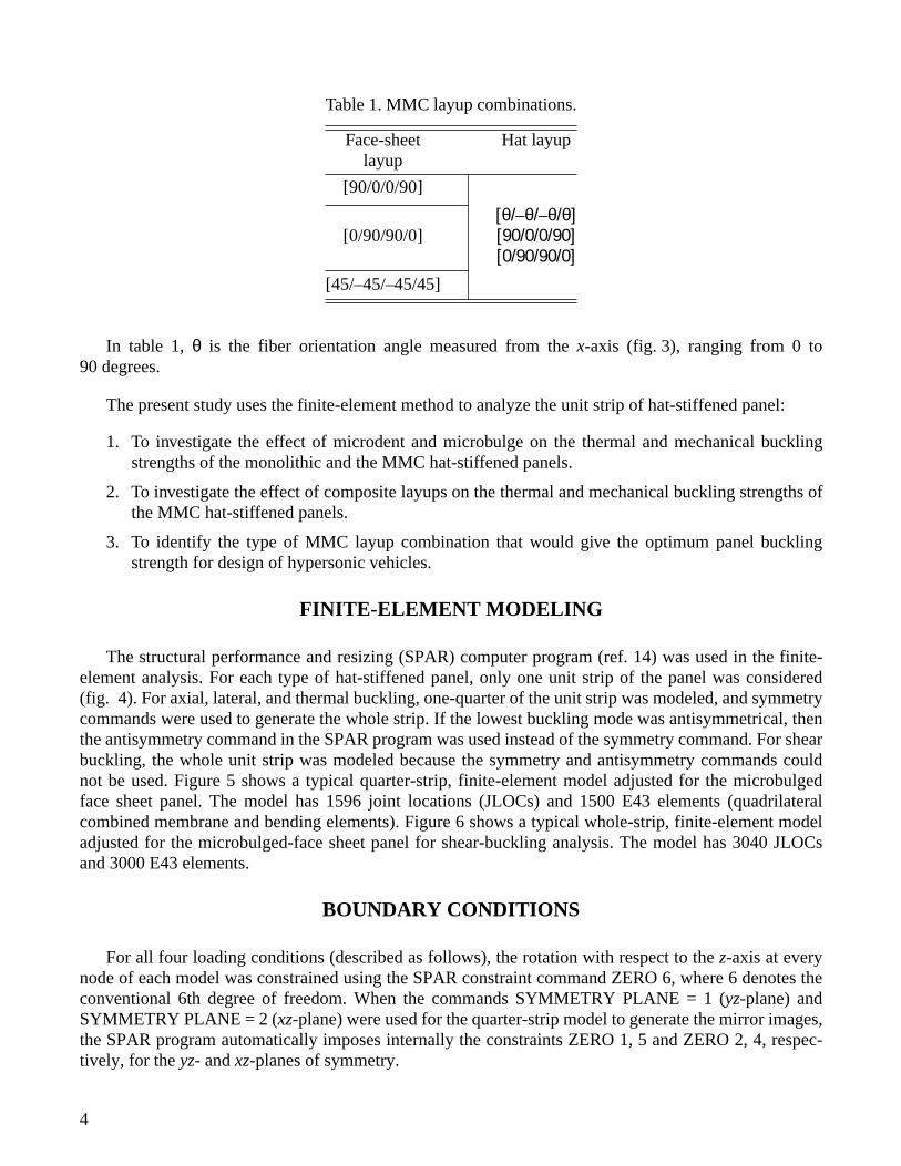
In table 1, θ is the fiber orientation angle measured from the x-axis (fig. 3), ranging from 0 to90 degrees.
The present study uses the finite-element method to analyze the unit strip of hat-stiffened panel:
1. To investigate the effect of microdent and microbulge on the thermal and mechanical bucklingstrengths of the monolithic and the MMC hat-stiffened panels.
2. To investigate the effect of composite layups on the thermal and mechanical buckling strengths ofthe MMC hat-stiffened panels.
3. To identify the type of MMC layup combination that would give the optimum panel bucklingstrength for design of hypersonic vehicles.
FINITE-ELEMENT MODELING
The structural performance and resizing (SPAR) computer program (ref. 14) was used in the finite-element analysis. For each type of hat-stiffened panel, only one unit strip of the panel was considered(fig. 4). For axial, lateral, and thermal buckling, one-quarter of the unit strip was modeled, and symmetrycommands were used to generate the whole strip. If the lowest buckling mode was antisymmetrical, thenthe antisymmetry command in the SPAR program was used instead of the symmetry command. For shearbuckling, the whole unit strip was modeled because the symmetry and antisymmetry commands couldnot be used. Figure 5 shows a typical quarter-strip, finite-element model adjusted for the microbulgedface sheet panel. The model has 1596 joint locations (JLOCs) and 1500 E43 elements (quadrilateralcombined membrane and bending elements). Figure 6 shows a typical whole-strip, finite-element modeladjusted for the microbulged-face sheet panel for shear-buckling analysis. The model has 3040 JLOCsand 3000 E43 elements.
BOUNDARY CONDITIONS
For all four loading conditions (described as follows), the rotation with respect to the z-axis at everynode of each model was constrained using the SPAR constraint command ZERO 6, where 6 denotes theconventional 6th degree of freedom. When the commands SYMMETRY PLANE = 1 (yz-plane) andSYMMETRY PLANE = 2 (xz-plane) were used for the quarter-strip model to generate the mirror images,the SPAR program automatically imposes internally the constraints ZERO 1, 5 and ZERO 2, 4, respec-tively, for the yz- and xz-planes of symmetry.
Table 1. MMC layup combinations.
Face-sheet layup
Hat layup
[90/0/0/90]
[0/90/90/0][θ/–θ/–θ/θ][90/0/0/90][0/90/90/0]
[45/–45/–45/45]
4

Axial Buckling
Axial buckling is buckling in the hat axial direction (i.e., x-direction). Figure 7 shows all the constraintconditions for the quarter-strip panel for axial buckling. Because the unit hat strip is part of the wholepanel, the closest boundary constraints were chosen to approximate the actual condition of the unit hatstrip, which is surrounded by the rest of the whole panel. Thus, at the ends of the unit strip, constraintZERO 3, 5 was imposed at the face sheet and hat flat regions. Along the long edges of the face sheet,constraint ZERO 2, 4 was imposed to allow the unit strip to deform freely in the z-direction, like thewhole panel.
Lateral Buckling
Lateral buckling is buckling in the direction transverse to the hat axial direction (i.e., y-direction).Figure 8 shows the constraint commands for lateral buckling. The two long edges of the face sheet aresimply supported (i.e., constraint ZERO 3). This edge condition could give the buckling mode shapesimilar to the whole-panel case. At each end of the face sheet and hat flat regions, constraint ZERO 1, 3,5 was imposed.
Shear Buckling
Figure 9 shows the constraint conditions for shear buckling of the whole unit strip. One long edge isfixed with constraint ZERO 1, 2, 3, 4; the other with constraint ZERO 2, 3, 4. The ends of the face sheetare constrained with ZERO 3, 5. The ends of the hat are unconstrained.
Thermal Buckling
Figure 10 shows the constraint conditions for thermal buckling. The long side of the face sheet isconstrained with ZERO 2, 3, 4; the ends of the face sheet and hat flat region with constraint ZERO 1, 3, 5.
APPLIED LOADS
Axial Buckling
For axial buckling, an unit axial compressive load = 1 lb was applied. This axial load was distrib-uted over the nodes of the cross-section of the unit strip (i.e., face sheet and hat cross-sections; fig. 11) togenerate an uniform axial compressive stress of
(1)
where A is the cross-sectional area of the unit strip. The effective panel load for the unit strip isdefined as
(2)
Fx
σx
Fx
A------= 1
A---=
Nx
Nx
Fx
2 p------= 1
2 p------=
5

The input nodal force at node i of a finite-element model is calculated from
(3)
where and are the cross-sectional areas of the two adjacent elements at node i.
If the node i is at the juncture where the face sheet and hat meet, the nodal force is calculated from
(4)
where is the cross-sectional area of the hat element adjacent to the juncture node i.
If the node i is at the corner of the face sheet, then is calculated from
(5)
Lateral Buckling
For lateral buckling, the panel lateral compressive load = 1 lb/in. was applied only to the longedges of the face sheet. The lateral compressive nodal force at node i is then calculated from
(6)
where and are the widths of the two adjacent edge elements at node i.
When node i is at the corner of the face sheet, equation (6) becomes
(7)
Shear Buckling
For shear buckling, the panel shear load = 1 lb/in. was applied at the edges of the face sheet only.The shear nodal force at node i was calculated from
(8)
or
(9)
if node i is at the corner of the face sheet.
Thermal Buckling
For thermal buckling, the panel was subjected to a uniform temperature field. The uniform nodaltemperature of ∆T = 1 °F was used as thermal load input to every node of the finite-element models.
Pi
Pi12--- A i –1 A i + ( )σ x =
Ai–1 Ai
Pi
Pi12--- A i –1 A +
i A h + ( )σ x =
Ah
Pi
Pi12--- A i σ x =
NyQi
Qi12--- L i –1 L i + ( ) N y =
Li–1 Li
Qi12--- L i N y =
NxyRi
Ri12--- L i –1 L i + ( ) N xy =
Ri12--- L i N xy =
6

In calculating buckling temperature , a problem is that the input material properties, which aretemperature dependent, must correspond to the unknown buckling temperature + , where isroom temperature (70
°
F). For this reason, one has to assume a temperature , and use the materialproperties corresponding to as inputs to calculate . This material property iteration process mustcontinue until the assumed temperature approaches the calculated buckling temperature + .Thus, the thermal buckling solution process requires both eigenvalue and material property iterations.
BUCKLING LOADS AND TEMPERATURES
If , , , and are the lowest eigenvalues for the axial, lateral, shear, and thermal bucklingcases, respectively, then the buckling loads , , , and the buckling temperature
associated with the four buckling cases may be obtained by multiplying the respective appliedloads and temperature by the corresponding eigenvalues (i.e., scaling factors) as
; (10)
; (11)
; (12)
; (13)
In the eigenvalue extractions that the SPAR program uses, the iterative process consists of a Stodolamatrix iteration procedure, followed by a Rayleigh-Ritz procedure, and finally a second Stodola proce-dure. This process results in successively refined approximations of
m
eigenvectors associated with the
m
eigenvalues. Reference 14 describes the detail of this process.
NUMERICAL EXAMPLES
Tables 2 and 3 show geometrical dimensions and material properties, respectively, for the monolithicand the metal-matrix composite hat-stiffened panels.
Table 2. Geometry ofthe hat-stiffened panel.
a
= 0.64 in.
b = 0.4 in. d
= 0.015 or 0.03 in.
h
= 1.25 in.
p
= 1.46 in.
r
= 0.33 in.= 0.032 in.
= 0.032 in.
∆Tcr∆Tcr Tr Tr
TaTa ∆Tcr
Ta ∆Tcr Tr
λx λy λxy λTNx( )
crNy( )
crNxy( )
cr∆Tcr
Nx( )cr
λxNx
λx
2 p------= = Nx
12 p------=
Ny( )cr
λyNy λy= = Ny 1=
Nxy( )cr
λxyNxy λxy= = Nxy 1=
∆Tc rλT∆T λT= = ∆T 1=
tcts
7

Note that two values of d were used for the microdented and microbulged face-sheet cases.
The data in table 4 were plotted in figure 12 to show the nonlinearity of the temperature-dependentmaterial property curves.
MATERIAL PROPERTY ITERATIONS
Monolithic Panels
As mentioned earlier, calculations of buckling temperatures require material property iterations.Figure 13 illustrates the iteration process for calculation of buckling temperatures for a panel witha microdented face sheet. The calculated buckling temperature is plotted against the assumedtemperature for the material properties. The 45-degree line represents the solution line for the buck-ling temperature . For example, if the assumed material temperature agrees with the calculatedbuckling temperature + , then the data point of falls right on the 45-degree line. In the firstiteration, the material properties at, for example, = = 70 °F was used to calculate the first buck-ling temperature . The second iteration then uses the material properties at any other temperature,for example, = 300 °F, to update the input material properties to calculate the second bucklingtemperature . In the third iteration, the two data points and were connected
Table 3. Temperature-dependent material properties for monolithic titanium (Ti-6Al-4V, ref. 15).
70 °F 200 °F 300 °F 400 °F 500 °F 600 °F 700 °F 800 °F 900 °F 1000 °F
E, lb/in2 × 106 16.0 15.28 14.80 14.40 14.02 13.63 13.15 12.64 11.84 10.56
G, lb/in2 × 106 6.20 5.83 5.65 5.50 5.37 5.20 5.02 4.82 4.52 4.03
ν 0.31 0.31 0.31 0.31 0.31 0.31 0.31 0.31 0.31 0.31
α, in/in-°F × 10–6 4.85 5.00 5.10 5.19 5.27 5.36 5.44 5.52 5.59 5.62
Table 4. Temperature-dependent material propertiesfor metal-matrix composite.
70 °F 1200 °F
, lb/in2 27.72 × 10⁶ 23.22 × 10⁶
, lb/in2 18.08 × 10⁶ 8.69 × 10⁶
, lb/in2 8.15 × 10⁶ 3.5 × 10⁶
0.3 0.3
, in/in-°F 2.16 × 10⁻⁶ 3.21 × 10⁻⁶
, in/in-°F 4.61 × 10⁻⁶ 6.15 × 10⁻⁶
, in/in-°F 0.0 0.0
E11
E22
G12
ν12
α11α22
α12
∆Tcr∆Tcr
Ta∆Tcr Ta
∆Tcr Tr ∆TcrTa( )
1Tr
∆Ta( )1
Ta( )2
∆Tcr( )2
∆Tcr( )1
∆Tcr( )2
8

with a straight line to locate the intersection point with the 45-degree line, and then this intersection-pointtemperature was used to update the material properties for calculation of the third buckling temperature
. This iteration process continues until the nth-calculated buckling temperature datapoint falls right on the 45-degree solution line.
From the geometry of figure 9, may be expressed as a function of and as
(14)
For the present monolithic material, the data point (less than 400 °F) falls practically on the45-degree solution line, giving an acceptable solution for (less than 0.5 percent error). That is, thevalue of calculated from the third material iteration practically agrees with that obtained fromequation (14), because the material property curves (fig. 12) are almost linear in the range 0 < T < 500 °F.
Metal-Matrix Composite Panels
Because of the lack of material data between room temperature and 1200 °F, linear interpolation wasused to find the material properties at any temperature. Figure 14 shows the material property iterationprocess for a typical composite panel with [90/0/0/90] flat face sheet and [45/–45/–45/45] hat. Similarto the monolithic case, in the first iteration, the data point was calculated using the room-temperature material properties. In calculating , a new temperature = + {where = }, instead of any temperature on the right-hand side of the 45-degree line, was used toupdate the input material properties. Because the coefficients of thermal expansion increase withtemperature, would fall below the 45-degree line. In the third iteration, similar to the monolithiccase, the two data points and were connected with a straight line that intersects the45-degree solution line. Then, the temperature at the intersection point was used to update the materialproperties for the calculations of the third data point . Because of the linear interpolation of thematerial properties, the data point falls right on the 45-degree solution line, giving the desiredthermal buckling solution.
The value of obtained from the material iteration process may be compared with the valueof calculated from
(15)
which was established using figure 14.
∆Tcr( )3
∆Tcr( )n
∆Tcr( )3
∆Tcr( )1
∆Tcr( )2
∆Tcr( )3
∆Tcr( )1
1∆Tcr( )
2∆Tcr( )
1–
Ta( )2
Ta( )1
–---------------------------------------------–
-------------------------------------------------------=
∆Tcr( )3
∆Tcr∆Tcr( )
3
∆Tcr( )1
∆Tcr( )2
Ta( )2
∆Tcr( )1
Ta( )1
Ta( )1
Trαij
∆Tcr( )2
∆Tcr( )1
∆Tcr( )2
∆Tcr( )3
∆Tcr( )3
∆Tcr( )3
∆Tcr( )3
∆Tcr( )3
∆Tcr( )1
2∆Tcr( )
2
∆Tcr( )1
-------------------–
-----------------------------=
9
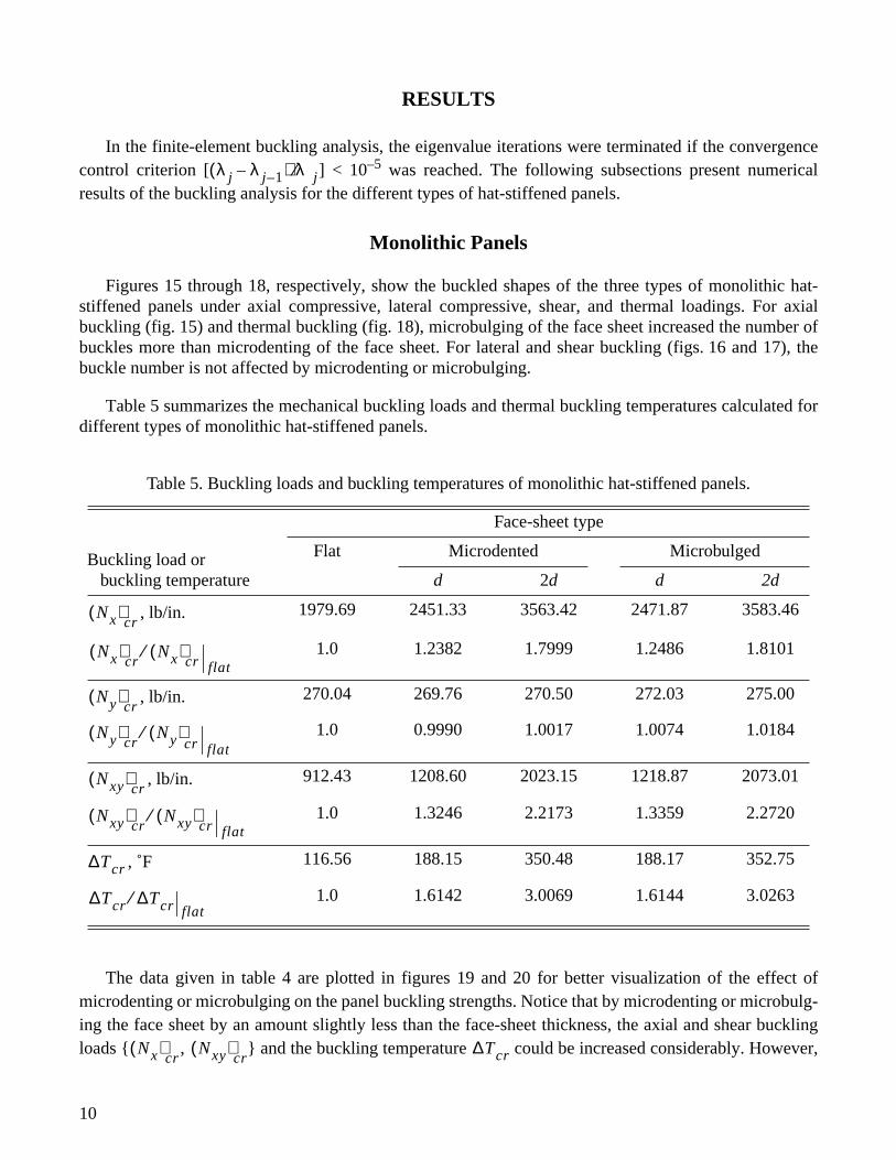
RESULTS
In the finite-element buckling analysis, the eigenvalue iterations were terminated if the convergencecontrol criterion [ ] < 10–5 was reached. The following subsections present numericalresults of the buckling analysis for the different types of hat-stiffened panels.
Monolithic Panels
Figures 15 through 18, respectively, show the buckled shapes of the three types of monolithic hat-stiffened panels under axial compressive, lateral compressive, shear, and thermal loadings. For axialbuckling (fig. 15) and thermal buckling (fig. 18), microbulging of the face sheet increased the number ofbuckles more than microdenting of the face sheet. For lateral and shear buckling (figs. 16 and 17), thebuckle number is not affected by microdenting or microbulging.
Table 5 summarizes the mechanical buckling loads and thermal buckling temperatures calculated fordifferent types of monolithic hat-stiffened panels.
The data given in table 4 are plotted in figures 19 and 20 for better visualization of the effect ofmicrodenting or microbulging on the panel buckling strengths. Notice that by microdenting or microbulg-ing the face sheet by an amount slightly less than the face-sheet thickness, the axial and shear bucklingloads { , } and the buckling temperature could be increased considerably. However,
Table 5. Buckling loads and buckling temperatures of monolithic hat-stiffened panels.
Face-sheet type
Buckling load or buckling temperature
Flat Microdented Microbulged
d 2d d 2d
, lb/in. 1979.69 2451.33 3563.42 2471.87 3583.46
1.0 1.2382 1.7999 1.2486 1.8101
, lb/in. 270.04 269.76 270.50 272.03 275.00
1.0 0.9990 1.0017 1.0074 1.0184
, lb/in. 912.43 1208.60 2023.15 1218.87 2073.01
1.0 1.3246 2.2173 1.3359 2.2720
, ˚F 116.56 188.15 350.48 188.17 352.75
1.0 1.6142 3.0069 1.6144 3.0263
λ j λ j–1–( ) λ j⁄
Nx( )cr
Nx( )cr
Nx( )cr
⁄ flat
Ny( )cr
Ny( )cr
Ny( )⁄cr
flat
Nxy( )cr
Nxy( )cr
Nxy( )cr
⁄ flat
∆Tcr
∆Tcr ∆Tcr⁄flat
Nx( )cr
Nxy( )cr
∆Tcr
10

the lateral buckling load is practically unaffected by microdenting or microbulging of the facesheet. The microbulged face-sheet case appears to be slightly more buckling efficient than the microdentedface-sheet case, which may be attributed to the increase in the moment of inertia about the neutral axis. Inactual applications, either the axis of the face-sheet microdent (or microbulge) is parallel to the free stream(fuselage-panel case) or normal to the freestream direction (wing-panel case), and the degree of aero-dynamic heating disturbance that the microdenting (or microbulging) causes remains to be investigated.
Metal-Matrix Composite Panels
The buckled shapes of the MMC hat-stiffened panels are very similar to those of the monolithic casesand, therefore, are not shown. Table 6 summarizes the mechanical and thermal buckling data for the com-posite panels with different degrees of face-sheet microdent or microbulge. The composite panels chosenfor this study have [90/0/0/90] face-sheet and [45/–45/–45/45] hat layups.
The mechanical and thermal buckling data of table 6 are plotted, respectively, in figures 21 and 22 asfunctions of the degree of microdent or microbulge
d
. It is seen that for the composite cases, the benefit ofthe microdenting or microbulging of the face sheets in increasing the axial and shear buckling loads{ , }, and the buckling temperatures , is similar to the case for monolithic panels.However, the degree of buckling load improvement is slightly lower for the composite panels (cf.,tables 5 and 6). Again, the microbulging of the face sheet is slightly more effective in improving the
Table 6. Buckling loads and buckling temperatures of MMC hat-stiffened panels with [90/0/0/90] facesheet and [45/–45/–45/45] hat.
Face-sheet type
Buckling load or buckling temperature
Flat Microdented Microbulged
d
2
d d
2
d
, lb/in. 2944.39 3344.24 4337.56 3366.47 4399.88
1.0 1.1358 1.4732 1.1434 1.4943
, lb/in. 715.63 738.31 750.73 724.42 726.12
1.0 1.0317 1.0490 1.0123 1.0147
, lb/in. 1401.33 1709.09 2702.55 1899.04 3075.62
1.0 1.2196 1.9286 1.3552 2.1948
, ˚F 195.18 252.37 413.53 275.96 439.43
1.0 1.2930 2.1187 1.4139 2.2514
Ny( )cr
Nx( )cr
Nx( )cr
Nx( )cr
⁄ flat
Ny( )cr
Ny( )cr
Ny( )cr
⁄flat
Nxy( )cr
Nxy( )cr
Nxy( )cr
⁄ flat
∆Tcr
∆Tcr ∆Tcr⁄flat
Nx( )cr
Nxy( )cr
∆Tcr
11

panel axial, shear, and thermal buckling strengths than microdenting of the face sheet. Like themonolithic case, the lateral buckling load is practically unaffected by either microdenting ormicrobulging of the face sheet.
Table 7 summarizes the mechanical and thermal buckling solutions for the flat-face-sheet, metal-matrix composite, hat-stiffened panels with different layups.
Table 7. Buckling loads and buckling temperatures of MMC hat-stiffened panels with flat face sheets.
Face-sheetlayup
Hatlayups
,lb/in.
,lb/in.
,lb/in.
,
°
F
90/0/0/90
0/0/0/0 3387.65 722.83 1406.97 189.95
15/–15/–15/15 3316.96 723.16 1406.41 190.42
30/–30/–30/30 3140.69 723.66 1404.43 192.45
45/–45/–45/45 2944.39 715.63 1401.33 194.97
60/–60/–60/60 2806.54 703.86 1398.01 197.34
75/–75/–75/75 2740.19 696.19 1395.22 198.75
90/–90/–90/90 2721.67 693.88 1394.02 200.00
90/0/0/90 3095.51 728.89 1402.88 195.26
0/90/90/0 3061.76 718.91 1400.85 194.47
0/90/90/0
0/0/0/0 3462.72 557.09 1072.94 149.71
15/–15/–15/15 3389.76 557.39 1072.64 150.50
30/–30/–30/30 3200.16 558.34 1071.39 152.78
45/–45/–45/45 2991.69 559.90 1069.18 155.70
60/–60/–60/60 2850.15 561.74 1066.61 158.86
75/–75/–75/75 2782.44 563.25 1064.27 161.48
90/–90/–90/90 2764.38 563.83 1063.25 162.57
90/0/0/90 3149.51 566.31 1069.73 155.92
0/90/90/0 3114.00 557.41 1068.56 156.23
45/–45/–45/45
0/0/0/0 3662.30 619.45 1256.47 168.36
15/–15/–15/15 3594.30 619.86 1255.68 169.21
30/–30/–30/30 3386.48 621.19 1253.19 171.59
45/–45/–45/45 3169.40 623.37 1249.61 175.11
60/–60/–60/60 3017.60 625.99 1246.06 177.82
75/–75/–75/75 2945.04 628.14 1243.24 179.78
90/–90/–90/90 2938.29 628.97 1242.07 181.06
90/0/0/90 3341.18 632.31 1251.30 175.04
0/90/90/0 3300.32 619.66 1249.77 175.14
Ny( )cr
Nx( )cr
Ny( )cr
Nxy( )cr
∆Tcr
12

Figure 23 shows the axial, lateral, and shear buckling loads { , , }, respectively,plotted against the hat-fiber orientation angle
θ
for the metal-matrix composite, hat-stiffened panels withflat face sheets having three types of layups. In the figure, two types of hat layups, [90/0/0/90] and [0/90/90/0] (indicated by 90/0 and 0/90 on the
θ
axis, respectively), are added for comparison.
The axial buckling load decreases with the increase of
θ
; however, both the lateral and shearbuckling loads { , } are insensitive to the change of
θ
. Notice that for any hat fiber orienta-tion
θ
, the panels with [45/–45/–45/45] face sheet have the highest axial buckling strength compared withthe panels having [90/0/0/90] and [0/90/90/0] face sheets. This phenomenon was also observed in thecase of buckling of composite sandwich panels studied by Ko and Jackson earlier (ref. 4).
The buckling strength of the panel depends not only on the longitudinal stiffness but also on the lateraland shear stiffnesses (ref. 5). For this reason, the [45/–45/–45/45] face sheet turned out to provide higheraxial buckling strength than the other two types of face sheets. For both lateral and shear buckling, panelswith [90/0/0/90] face sheet combined with any hat layup (i.e.,
θ
) ranks at the top among the three face-sheet cases studied.
Based on figure 23, the panel with optimum axial-buckling strength is the one with [45/–45/–45/45]face sheet and [0/0/0/0] hat. However, the [0/0/0/0] unidirectional composite lacks sufficient transversetensile strength. For practical purposes, the hat layups in the range of 10 deg <
θ
< 30 deg and the [90/0/0/90] and [0/90/90/0] hats could provide quasi-optimum axial-buckling strength for the panels.
Figure 24 shows the buckling temperature plotted against the hat fiber orientation angle
θ
forthe metal-matrix composite, hat-stiffened panels with flat face sheets having three types of layups. Thepanels with [90/0/0/90] face sheet give the highest thermal buckling strength among the three face-sheetcases. As shown in the figure, increases slightly with the increase of
θ
for any face-sheet layup(except for 90/0 and 0/90 hat layup cases).
CONCLUDING REMARKS
Thermal and mechanical buckling characteristics of monolithic and metal-matrix composite hat-stiffened panels were investigated. The study focused on the effect of face-sheet microdenting andmicrobulging on the panel buckling strengths. Also, for the metal-matrix composite panels, the effect offiber orientation on the panel buckling strengths was investigated. The key findings of the study areas follows:
1. Microdenting and microbulging of the face sheet could greatly enhance the axial, shear, andthermal buckling strengths of the hat-stiffened panels. However, the lateral buckling strength isnot affected by either microdenting or microbulging of the face sheet.
2. Microbulging of the face sheet is slightly more efficient than microdenting of the face sheet inincreasing the panel axial, shear, and thermal buckling strengths.
3. For any hat layup, the composite hat-stiffened panels using [45/–45/–45/45] face sheet havehigher axial-buckling strengths than those using [90/0/0/90] or [0/90/90/0] face sheet.
Nx( )cr
Ny( )cr
Nxy( )cr
Nx( )cr
Nx( )cr
Nxy( )cr
∆Tcr
∆Tcr
13

4. For the composite panels with any face-sheet layup, the axial buckling strength decreases withthe increase of the hat fiber orientation angle. However, the lateral, shear, and thermal bucklingloads are insensitive to the change of hat fiber orientation. The composite hat-stiffened panels with[45/–45/–45/45] face sheet combined with [90/0/0/90] hat, [0/90/90/0] hat, or [
θ
/–
θ
/–
θ
/
θ
] hat(10 deg <
θ
< 30 deg), offer optimum axial-buckling strength.
5. The effect of microdenting or microbulging on the improvement of buckling strengths is moreconspicuous for the monolithic hat-stiffened panels than for the MMC hat-stiffened panels.
Dryden Flight Research CenterNational Aeronautics and Space AdministrationEdwards, California, April 22, 1996
14

REFERENCES
1. Siegel, William H.,
Experimental and Finite Element Investigation of the Buckling Characteristicsof a Beaded Skin Panel for a Hypersonic Aircraft
, NASA CR-144863, April 1978.
2. Ko, William L., John L. Shideler, and Roger A. Fields,
Buckling Characteristics of HypersonicAircraft Wing Tubular Panels
, NASA TM-87756, December 1986.
3. Ko, William L. and Raymond H. Jackson,
Thermal Behavior of a Titanium Honeycomb-CoreSandwich Panel
, NASA TM-101732, January 1991.
4. Ko, William L. and Raymond H. Jackson,
Compressive and Shear Buckling Analysis of MetalMatrix Composite Sandwich Panels Under Different Thermal Environments
, NASA TM-4492,June 1993.
5. Ko, William L.,
Mechanical and Thermal Buckling Analysis of Rectangular Sandwich Panels UnderDifferent Edge Conditions
, NASA TM-4585, April 1994.
6. Ko, William L.,
Predictions of Thermal Buckling Strengths of Hypersonic Aircraft Sandwich PanelsUsing Minimum Potential Energy and Finite Element Methods
, NASA TM-4643, May 1995.
7. Percy, Wendy C. and Roger A. Fields, “Buckling of Hot Structures,” Eighth National Aero-SpacePlane Symposium, Naval Postgraduate School, Monterey, California, Mar. 26–30, 1990.
8. Percy, W. and R. Fields, “Buckling Analysis and Test Correlation of Hat Stiffened Panels forHypersonic Vehicles,” AIAA-90-5219, presented at AIAA 2nd International Aerospace PlanesConference, Orlando, Florida, Oct. 29–31, 1990.
9. Teare, Wendy P. and Roger A. Fields, “Buckling Analysis and Test Correlation of High TemperatureStructural Panels,”
Thermal Structures and Materials for High-Speed Flight
, Earl A. Thornton, ed.,vol. 140, Progress in Astronautics and Aeronautics, AIAA, Washington, DC, 1992, pp. 337–352.
10. Ko, William L. and Raymond H. Jackson,
Compressive Buckling Analysis of Hat-Stiffened Panel
,NASA TM-4310, August 1991.
11. Hudson, Larry D. and Randolph C. Thompson, Single-Strain-Gage Force/Stiffness Buckling Predic-tion Techniques on a Hat-Stiffened Panel
, NASA TM-101733, February 1991.
12. Thompson, Randolph C. and W. Lance Richards,
Thermal–Structural Panel Buckling Tests
, NASATM-104243, December 1991.
13. Ko, William L. and Raymond H. Jackson,
Shear Buckling Analysis of a Hat-Stiffened Panel
, NASATM-4644, November 1994.
14. Whetstone, W.D.,
SPAR Structural Analysis System Reference Manual, System Level 13A
, vol. 1,Program Execution, NASA CR-158970-1, December 1978.
15. MIL-Handbook-5B, Aug. 31, 1973.
15
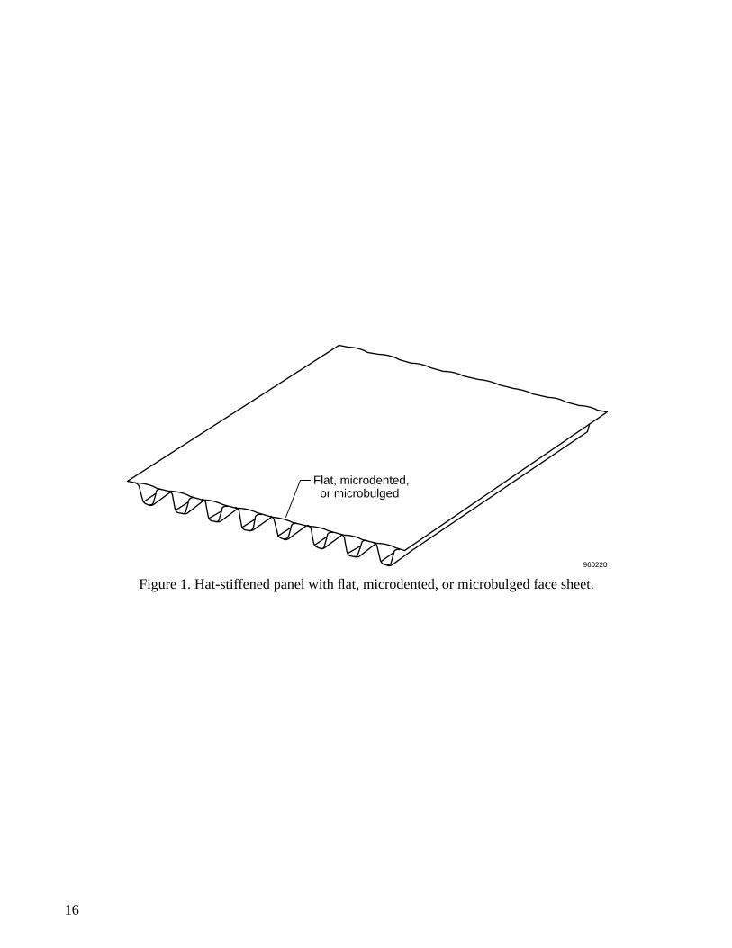
Figure 1. Hat-stiffened panel with flat, microdented, or microbulged face sheet.
960220
Flat, microdented, or microbulged
16

Figure 2. Three types of hat-stiffened panels.
960422
d
d
960421
a
tc ts
960420
b
r
r
h
p
17

Figure 3. Composite layups for hat-stiffened panels.
Figure 4. Unit strip of a hat-stiffened panel.
960221
[90/0/0/90],[0/90/90/0], or[45/–45/–45/45]
[θ/– θ/– θ/θ],[90/0/0/90], or[0/90/90/0]
x
y
z
Hat
Face sheet
–θ θ
Quarter region modeled for axial, lateral, thermal buckling
Full region modeled for shear buckling
z
y
x
960423
18

Figure 5. Quarter-unit strip finite-element model; microbulged face sheet.
Figure 6. Full-unit strip finite-element model; microbulged face sheet.
y
z
x
JLOC 1596
E43 1500
960424
x
z
y
960425
JLOC 3040
E43 3000
19
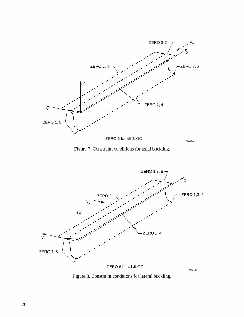
Figure 7. Constraint conditions for axial buckling.
Figure 8. Constraint conditions for lateral buckling.
ZERO 3, 5
ZERO 2, 4
ZERO 1, 5
ZERO 2, 4
Fx
ZERO 3, 5
x
z
y
ZERO 6 for all JLOC
960426
ZERO 2, 4
960427
ZERO 3
ZERO 1, 5
x
z
ZERO 1,3, 5
ZERO 1,3, 5
Ny
y
ZERO 6 for all JLOC
20

Figure 9. Constraint conditions for shear buckling.
Figure 10. Constraint conditions for thermal buckling.
ZERO 6 for all JLOC
ZERO 1, 2, 3, 4
ZERO 3, 5x
y
zNxy
ZERO 3, 5
ZERO 2, 3, 4
960428
ZERO 1, 5
y
ZERO 6 for all JLOC
ZERO 2, 4
ZERO 1, 3, 5
ZERO 1, 3, 5
x
∆T
ZERO 2, 3, 4
Z
960429
21

Figure 11. Distributions of applied compressive forces.
Figure 12. Temperature-dependent material properties; Ti-6A1-4V titanium alloy.
960430
α
E
7 x 10-617 x 106
16
15
14
13
12
11
100 100 200 300 400 500 600 700 800 900 1000
6
5
4
3
2
1
0
T, °F960431
α, in./in. -°F
E, lb/in2
22

Figure 13. Iterations of buckling temperatures; monolithic hat-stiffened panel; microdented face sheet.
Figure 14. Iterations of buckling temperatures; metal-matrix composite hat-stiffened panel; [90/0/0/90]flat face sheet, [45/–45/–45/45] hat.
d = 0.015 in.
∆Tcr,°F
300
200
Solution line
100
0 300 400200100Ta
, °F 960432
(∆Tcr)3(∆Tcr)1 (∆Tcr)2
(Ta)2
(Ta)1=Tr = 70
First iterationSecond iterationThird iteration solution
(∆Tcr)1(Ta)1
(∆Tcr)2 - 1 -
(∆Tcr)3 = (∆Tcr)1
(Ta)2 -
d = 0
Solution line
960433
∆Tcr, °F
300
200
100
0 300 400200100Ta
, °F (Ta)1=Tr = 70
(∆Tcr)3
(∆Tcr)1 (∆Tcr)2
(Ta)2 = (∆Tcr)1 + Tr
First iteration Second iteration Third iteration solution
(Ta)1
(∆Tcr)2 2 -
(∆Tcr)3 = (∆Tcr)1
23

Figure 15. Buckled shapes of three types of hat-stiffened panels under axial compression; monolithicpanels.
Fx
Fx
Fx
Fx
Fx
Fx
Flat
Microdented
Microbulged
960434
24
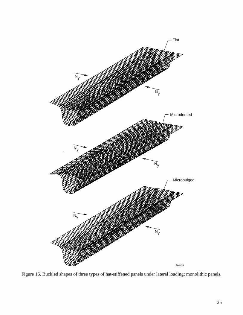
Figure 16. Buckled shapes of three types of hat-stiffened panels under lateral loading; monolithic panels.
Flat
Ny
Ny
Ny
Ny
Ny
Ny
Microdented
Microbulged
960435
25
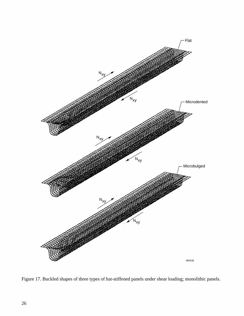
Figure 17. Buckled shapes of three types of hat-stiffened panels under shear loading; monolithic panels.
960436
Flat
Microdented
Microbulged
Nxy
Nxy
Nxy
Nxy
Nxy
Nxy
26

Figure 18. Buckled shapes of three types of hat-stiffened panels under uniform temperature loading; fouredges clamped; monolithic panels.
Microdented
Flat
Microbulged
∆T
960437
∆T
∆T
27

Figure 19. Buckling loads as functions of dent or bulge; monolithic hat-stiffened panels.
Figure 20. Increase of buckling temperatures with increase of dent or bulge; monolithic hat-stiffenedpanels.
4000
3500
3000
2500
Bucklingload,lb/in.
2000
1500
1000
500
0 .01d, in..02 .03 .04
960438
DentedBulged
(Nxy)cr
(Nx)cr
(Ny)cr
d
400
350
300
250
200
150
100
50.010
d, in..02 .03 .04
960439
Dented Bulged
d
∆Tcr, °F
28

Figure 21. Buckling loads as functions of dent or bulge; metal-matrix composite hat-stiffened panels; [90/0/0/90] face sheet, [45/–45/–45/45] hat.
Figure 22. Increase of buckling temperatures with increase of dent or bulge; metal-matrix composite hat-stiffened panel; [90/0/0/90] face sheet; [45/–45/–45/45] hat.
4500
4000
3500
3000
2500Bucklingload,lb/in. 2000
1500
1000
500
0 .01d, in..02 .03 .04
(Nx)cr
(Nxy)cr
(Ny)cr
960222
DentedBulged
d
450
400
350
300
250
200
150
0 .01d, in..02 .03 .04
960223
∆Tcr, °F
Dented Bulged
d
29

Figure 23. Buckling loads as functions of hat fiber orientation angle; metal-matrix composite hat-stiffened panels with three types of face-sheet layups; flat face sheet (d = 0).
Figure 24. Buckling temperatures as functions of hat fiber orientation; metal-matrix composite hat-stiffened panels; flat face sheet (d = 0).
4000
3000
2000
1000
0 15 30 45 60 75 90 90/0 0/90
[90/0/0/90][0/90/90/0][45/–45/–45/45]
d = 0
Face sheetlayup
θ, deg
(Nx)cr
(Nxy)cr
(Ny)cr
960224
Buckling load,lb/in.
200
100
300
0 15 30 45 60 75 90 90/0 0/90θ, deg
960225
[90/0/0/90] [0/90/90/0] [45/–45/–45/45]
d = 0Face sheet layup
∆Tcr, °F
30

REPORT DOCUMENTATION PAGE Form ApprovedOMB No. 0704-0188
Public reporting burden for this collection of information is estimated to average 1 hour per response, including the time for reviewing instructions, searching existing data sources, gathering and maintaining the data needed, and completing and reviewing the collection of information. Send comments regarding this burden estimate or any other aspect of this col-lection of information, including suggestions for reducing this burden, to Washington Headquarters Services, Directorate for Information Operations and Reports, 1215 Jefferson Davis Highway, Suite 1204, Arlington, VA 22202-4302, and to the Office of Management and Budget, Paperwork Reduction Project (0704-0188), Washington, DC 20503.
1. AGENCY USE ONLY (Leave blank) 2. REPORT DATE 3. REPORT TYPE AND DATES COVERED
4. TITLE AND SUBTITLE 5. FUNDING NUMBERS
6. AUTHOR(S)
8. PERFORMING ORGANIZATION REPORT NUMBER
7. PERFORMING ORGANIZATION NAME(S) AND ADDRESS(ES)
9. SPONSORING/MONOTORING AGENCY NAME(S) AND ADDRESS(ES) 10. SPONSORING/MONITORING AGENCY REPORT NUMBER
11. SUPPLEMENTARY NOTES
12a. DISTRIBUTION/AVAILABILITY STATEMENT 12b. DISTRIBUTION CODE
13. ABSTRACT (Maximum 200 words)
14. SUBJECT TERMS 15. NUMBER OF PAGES
16. PRICE CODE
17. SECURITY CLASSIFICATION OF REPORT
18. SECURITY CLASSIFICATION OF THIS PAGE
19. SECURITY CLASSIFICATION OF ABSTRACT
20. LIMITATION OF ABSTRACT
NSN 7540-01-280-5500 Standard Form 298 (Rev. 2-89)Prescribed by ANSI Std. Z39-18298-102
Thermal and Mechanical Buckling Analysis of Hypersonic Aircraft Hat-Stiffened Panels with Varying Face Sheet Geometry and Fiber Orientation
WU 505-63-50
William L. Ko
NASA Dryden Flight Research CenterP.O. Box 273Edwards, California 93523-0273
H-2097
National Aeronautics and Space AdministrationWashington, DC 20546-0001 NASA TM-4770
Mechanical and thermal buckling behavior of monolithic and metal-matrix composite hat-stiffened panelswere investigated. The panels have three types of face-sheet geometry: flat face sheet, microdented face sheet,and microbulged face sheet. The metal-matrix composite panels have three types of face-sheet layups, each ofwhich is combined with various types of hat composite layups. Finite-element method was used in the eigenvalueextractions for both mechanical and thermal buckling. The thermal buckling analysis required both eigenvalueand material property iterations. Graphical methods of the dual iterations are shown. The mechanical and thermalbuckling strengths of the hat-stiffened panels with different face-sheet geometry are compared. It was found thatby just microdenting or microbulging of the face sheet, the axial, shear, and thermal buckling strengths of bothtypes of hat-stiffened panels could be enhanced considerably. This effect is more conspicuous for the monolithicpanels. For the metal-matrix composite panels, the effect of fiber orientations on the panel buckling strengths wasinvestigated in great detail, and various composite layup combinations offering high panel buckling strengths arepresented. The axial buckling strength of the metal-matrix panel was sensitive to the change of hat fiberorientation. However, the lateral, shear, and thermal buckling strengths were insensitive to the change of hat fiberorientation.
Hat-stiffened panels; Mechanical buckling; Metal-matrix composites; Thermal buckling; Varying face sheet geometry; Varying fiber orientation
A03
37
Unclassified Unclassified Unclassified Unlimited
December 1996 Technical Memorandum
Available from the NASA Center for AeroSpace Information, 800 Elkridge Landing Road, Linthicum Heights, MD 21090; (301)621-0390
Unclassified—UnlimitedSubject Category 39