Embed Size (px)
Citation preview
at SciVerse ScienceDirect
Applied Thermal Engineering 35 (2012) 145e156
Contents lists available
Applied Thermal Engineering
journal homepage: www.elsevier .com/locate/apthermeng
Thermal analysis of mass concrete embedded with double-layer staggeredheterogeneous cooling water pipes
Jian Yang a,b, Yu Hu a, Zheng Zuo a, Feng Jin a,*, Qingbin Li a
a State Key Laboratory of Hydroscience and Engineering, Tsinghua University, 100084 Beijing, ChinabClean Energy Research Institute, China Huaneng Group, 100098 Beijing, China
a r t i c l e i n f o
Article history:Received 18 April 2011Accepted 4 October 2011Available online 19 October 2011
Keywords:Mass concreteHydration heatCooling water pipeEquivalent equation of heat conductionAdiabatic temperature rise curve
* Corresponding author. Tel.: þ86 0 1062794242; faE-mail addresses: [email protected] (J. Yang), yu
[email protected] (F. Jin).
1359-4311/$ e see front matter � 2011 Elsevier Ltd.doi:10.1016/j.applthermaleng.2011.10.016
a b s t r a c t
Removal of hydration heat frommass concrete during construction is important for the quality and safety ofconcrete structures. In this study, a three-dimensional finite element program for thermal analysis of massconcreteembeddedwithdouble-layer staggeredheterogeneous coolingwaterpipeswasdevelopedbasedonthe equivalent equation of heat conduction including the effect of cooling water pipes and hydration heat ofconcrete. The cooling function of the double-layer staggered heterogeneous cooling pipes in a concrete slabwas derived from the principle of equivalent cooling. To improve the applicability and precision of theequivalent heat conduction equation under small flow, the cooling function was revised according to itsmonotonicity and empirical formulas of single-phase forced-convection heat transfer in tube flow. Consid-ering heat hydration of concrete at later age, a double exponential functionwas proposed to fit the adiabatictemperature rise curve of concrete. Subsequently, the temperature variation of concrete was obtained, andtheoutlet temperatureof coolingwaterwasestimatedthroughtheenergyconservationprinciple.Comparingcalculated results with actual measured data from amonolith of an arch dam in China, the numerical modelwas proven to be effective in sufficiently simulating accurate temperature variations of mass concrete.
� 2011 Elsevier Ltd. All rights reserved.
1. Introduction
Mass concrete has been widely used in civil engineering, e.g.dam, building, and bridge construction, and is usually poured inlarge thin slabs. Due to the relatively small conductivity of concrete,little hydration heat diffuses from the surface during construction,so that internal temperature easily rises to exceed 70 �C. It may leadto thermal-stress-induced cracking and structural weakening [1,2].Moreover, the next slab cannot be poured until the previous slabhas been refrigerated to a prescribed temperature level, whichoften delays the construction process. Measures should be adoptedto limit the temperature rise in mass concrete within an acceptablelevel [3]. In addition to the application of pre-cooling techniques(e.g. cooling aggregates and reducing cement content), post-cooling of in-place concrete by circulating a cool liquid(commonly cold water) through built-in thin-walled pipes fora considerable amount of time is also widely used. This post-cooling technique was first successfully employed during theconstruction of the Hoover dam [4]. Instead of using full airconditioning, the use of a hydronic system in multi-story office
x: þ86 0 [email protected] (Y. Hu),
All rights reserved.
buildings where pipes embedded in the concrete slabs circulatecold or hot water in different seasons has been introduced [5].
Thefirst solution to theproblemof embedded coolingwater pipeswas proposed by the U.S. Bureau of Reclamation after the completionof the Hoover dam [6]. Provided that cooling pipes are arranged atregular spatial intervals, the concrete could be regarded as a series ofunit cells with a pipe located at the cell center. Each unit cell can thenbe simplified as a long hollow circular cylinder with insulated outerboundary. Based on this assumption, the U.S. Bureau of Reclamationderived strict and approximate solutions to the two- and three-dimensional (3D) problem without an internal heat resource. Zhu[7] addressed the problem of heat resource. Above solutions remaineffective guides for engineers in the design and operation of coolingpipe systems up to the present [3,8]. However, this approach islimited by its inability to account for different construction condi-tions, different thermal properties of concrete, and arbitrary time-dependent variations in conditions of cooling water.
Based on the periodic temperature field along pipe arrangementdirections in mass concrete embedded in a rectangular pipe mesh,Liu [9] proposedan analyticmodel of temperature variation.Detaileddescriptions of the principal aspects affecting the temperature field,including concrete and pipe material properties, pipe sizes, pipespacing, and the cooling process, were presented. Charpin et al. [10]appliednon-dimensional analysis to theproblemofapipe embedded

Nomenclature
b parameter for equivalent material thermal diffusivity(Eq. (30))
c specific heat (J/kg �C)Cs StefaneBoltzman constant (5.669 � 10�8 W/m2 �C4)d inner diameter of cooling pipe (m)e emissivity of surfacef friction factorGt total amount of solar energy reaching the surface
(W/m2)h heat convection coefficient (W/m2 �C)hr linearized radiation coefficient (W/m2 �C)i the layer number of insulatork thermal conductivity (W/m �C)l thickness of the heat insulator (m)L length of cooling pipe (m)m a parameter that represents the heat generation rate
(1/day)n the normal to the surfaceNu Nusselt numberPr Prandtl numberq flow of cooling water (m3/s)qa absorbed solar radiation flux (W/m2)qc convective flux (W/m2)qcool heat absorbed by cooling water per unit time (W)qm1 turning point flow of cooling water (m3/s)qm2 critical laminar flow of cooling water (m3/s)qr radiative flux (W/m2)qs a scale factorQ total internal heat source per unit volume (J/m3)_Q the rate of total internal heat source per unit volume
(W/m3)r inner radius of the concrete cylinder (m)r0 outer radius of the cooling pipe (m)R outer radius of the concrete cylinder (m)Re Reynolds numberS spatial interval of the cooling pipe (m)t time (s)
tp thickness of cooling pipe (m)T temperature (�C)T0 initial temperature of concreteTa ambient air temperature (�C)Tc the concrete placing temperature (�C)Te the deep earth temperature (�C)Tm mean temperature of concrete cylinder (�C)Tw-in inlet temperature of cooling water (�C)Tw-out outlet temperature of cooling water (�C)um mean velocity of flow (m/s)
Greek symbolsa material thermal diffusivity (m2/s)a1, a2 parameters for adiabatic temperature rise curve of
double exponential function (Chapter 4)a0 equivalent material thermal diffusivity (m2/s)b a parameter about the rectangular aspect ratio
(Chapter 3.1)G the boundary surfaceGq the exposed surfacez solar absorptivityq adiabatic temperature rise of concrete (�C)q0 maximum temperature rise of concrete under
adiabatic conditions (�C)m dynamic viscosity (kg/m s)n kinematic viscosity (m2/s)x parameter for the cooling functionr material’s density (kg/m3)s time (s)4 cooling functionDt the time interval
Superscriptsn step numberw cooling waterp cooling pipeh horizontalv vertical
J. Yang et al. / Applied Thermal Engineering 35 (2012) 145e156146
in a long insulated cylindrical slabof concrete andreduced it to a one-dimensional heat equation. An analytic solution for the temperaturerise along the pipe and within the concrete was then derived.Following this study, Myers et al. [11] developed a numericalprocedure and discussed the effect of varying model parameters.However, the applicationof analyticmethods in engineering remainslimited because of its inconvenience and inflexibility.
Recently, finite element methods [12e15] have been developedand widely used in the thermal analysis of mass concrete withcooling pipe coils. Neglecting the temperature gradient at thedirection of the cooling pipe, Zhu et al. [12] presented an iterativemethod to obtain the temperature field of the concrete andwater. Aseries of cross sections with equidistance were taken in the direc-tion perpendicular to the cooling pipe and the temperature field ineach cross sectionwas analyzed by two-dimensional finite elementmethod. A refinable finite element mesh should be adopted nearthe pipe to ensure the accuracy of the solution. Kim et al. [13]implemented a line element for the modeling of pipe and appliedinternal flow theory for calculating temperature variations ofcooling water. In this program, the requirement that the lineelement for modeling of pipe must be located at an edge of or runacross a solid concrete element may lead to inconveniences in the
model preprocessing and considerable computational cost. There-fore, these methods are not sufficiently efficient for thermal andstress analysis of large-scale concrete structures. To overcome thisproblem, Zhu [16] introduced the effect of the cooling pipe as a heatsink or as a negative heat source, and proposed an equivalentequation of heat conduction to calculate the temperature variationwith the conventional finite element mesh. Although this is anapproximation method, the application of the equivalent equationof heat conduction in practical engineering projects has beenreported in previous literature [16,17]. To our best knowledge, theseapplications are concerned with a single cooling pipe material inconcrete. Upon consideration of construction progress and coolingefficiency, the layout of double-layer staggered heterogeneouscooling pipes in a concrete slab was gradually adopted.
In this paper, we developed a 3D finite element procedure forthermal analysis of mass concrete with a pipe cooling system. Thesolution for the effect of double-layer staggered heterogeneouscooling pipes was derived from the concept of equivalent cooling.To improve the applicability and precision of the equivalent heatconduction equation under laminar flow condition, the coolingfunction was revised according to empirical formulas of single-phase forced-convection heat transfer in tube flow. Considering
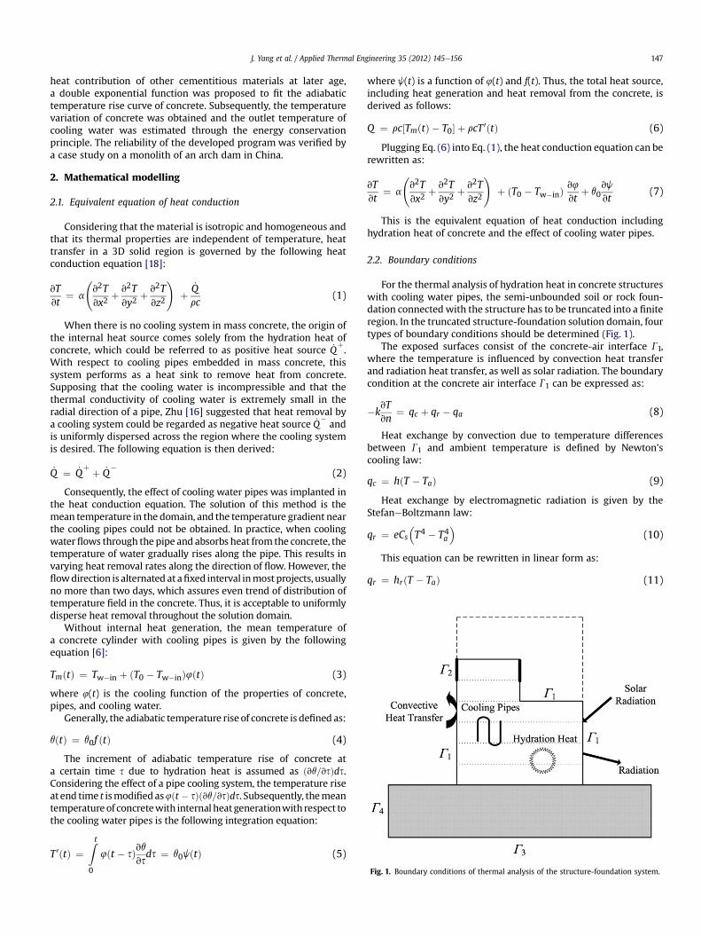
Fig. 1. Boundary conditions of thermal analysis of the structure-foundation system.
J. Yang et al. / Applied Thermal Engineering 35 (2012) 145e156 147
heat contribution of other cementitious materials at later age,a double exponential function was proposed to fit the adiabatictemperature rise curve of concrete. Subsequently, the temperaturevariation of concrete was obtained and the outlet temperature ofcooling water was estimated through the energy conservationprinciple. The reliability of the developed program was verified bya case study on a monolith of an arch dam in China.
2. Mathematical modelling
2.1. Equivalent equation of heat conduction
Considering that the material is isotropic and homogeneous andthat its thermal properties are independent of temperature, heattransfer in a 3D solid region is governed by the following heatconduction equation [18]:
vTvt
¼ a
v2Tvx2
þ v2Tvy2
þ v2Tvz2
!þ
_Qrc
(1)
When there is no cooling system in mass concrete, the origin ofthe internal heat source comes solely from the hydration heat ofconcrete, which could be referred to as positive heat source _Q
þ.
With respect to cooling pipes embedded in mass concrete, thissystem performs as a heat sink to remove heat from concrete.Supposing that the cooling water is incompressible and that thethermal conductivity of cooling water is extremely small in theradial direction of a pipe, Zhu [16] suggested that heat removal bya cooling system could be regarded as negative heat source _Q
�and
is uniformly dispersed across the region where the cooling systemis desired. The following equation is then derived:
_Q ¼ _Qþ þ _Q
�(2)
Consequently, the effect of cooling water pipes was implanted inthe heat conduction equation. The solution of this method is themean temperature in the domain, and the temperature gradient nearthe cooling pipes could not be obtained. In practice, when coolingwaterflows through the pipe and absorbs heat from the concrete, thetemperature of water gradually rises along the pipe. This results invarying heat removal rates along the direction of flow. However, theflowdirection is alternated at afixed interval inmost projects, usuallyno more than two days, which assures even trend of distribution oftemperature field in the concrete. Thus, it is acceptable to uniformlydisperse heat removal throughout the solution domain.
Without internal heat generation, the mean temperature ofa concrete cylinder with cooling pipes is given by the followingequation [6]:
TmðtÞ ¼ Tw�in þ ðT0 � Tw�inÞ4ðtÞ (3)
where 4(t) is the cooling function of the properties of concrete,pipes, and cooling water.
Generally, the adiabatic temperature rise of concrete is defined as:
qðtÞ ¼ q0f ðtÞ (4)
The increment of adiabatic temperature rise of concrete ata certain time s due to hydration heat is assumed as ðvq=vsÞds.Considering the effect of a pipe cooling system, the temperature riseat end time t ismodifiedas4ðt � sÞðvq=vsÞds. Subsequently, themeantemperatureof concretewith internal heatgenerationwith respect tothe cooling water pipes is the following integration equation:
T 0ðtÞ ¼Zt0
4ðt � sÞvqvsds ¼ q0jðtÞ (5)
where j(t) is a function of 4(t) and f(t). Thus, the total heat source,including heat generation and heat removal from the concrete, isderived as follows:
Q ¼ rc½TmðtÞ � T0� þ rcT 0ðtÞ (6)
Plugging Eq. (6) into Eq. (1), the heat conduction equation can berewritten as:
vTvt
¼ a
v2Tvx2
þ v2Tvy2
þ v2Tvz2
!þ ðT0 � Tw�inÞ
v4
vtþ q0
vj
vt(7)
This is the equivalent equation of heat conduction includinghydration heat of concrete and the effect of cooling water pipes.
2.2. Boundary conditions
For the thermal analysis of hydration heat in concrete structureswith cooling water pipes, the semi-unbounded soil or rock foun-dation connectedwith the structure has to be truncated into a finiteregion. In the truncated structure-foundation solution domain, fourtypes of boundary conditions should be determined (Fig. 1).
The exposed surfaces consist of the concrete-air interface G1,where the temperature is influenced by convection heat transferand radiation heat transfer, as well as solar radiation. The boundarycondition at the concrete air interface G1 can be expressed as:
�kvTvn
¼ qc þ qr � qa (8)
Heat exchange by convection due to temperature differencesbetween G1 and ambient temperature is defined by Newton’scooling law:
qc ¼ hðT � TaÞ (9)
Heat exchange by electromagnetic radiation is given by theStefaneBoltzmann law:
qr ¼ eCs�T4 � T4a
�(10)
This equation can be rewritten in linear form as:
qr ¼ hrðT � TaÞ (11)
J. Yang et al. / Applied Thermal Engineering 35 (2012) 145e156148
hr ¼ eCs�T2 þ T2a
�ðT þ TaÞ (12)
For simplicity, both convection and radiation heat transfercoefficients are usually combined to generate a comprehensiveconvection coefficient. The amount of absorbed solar radiation isgiven by
qa ¼ zGt (13)
Covered surfaces G2, which are covered by formworks or heatinsulators during the construction phase, are the second type ofboundary condition. In general, the boundary condition is stillexpressed as Eq. (8), but the convection coefficient of the coveredsurfaces should be modified as follows:
hs ¼ 1ð1=hÞ þPðli=kiÞ
(14)
In practice, the exposed and covered surfaces of concretestructures vary throughout the construction process. Thus, a certainsurface is alternately exposed and covered during construction.
The horizontal boundary of the truncated foundation G3 isusually a constant temperature:
TðsÞ ¼ Te (15)
At the vertical surfaces of the truncated foundation G4, theboundary condition is defined as
�kvTvn
¼ 0 (16)
2.3. Finite element formulation of heat transfer
In this paper, the finite element discretization of Eq. (7) withimplementation of the aforementioned boundary conditionsresults in:
½C��vTvt
�þ ½K�fTg ¼ fFg (17)
The matrices and vectors are defined as:
½C� ¼ZU
rc½N�T½N�dU (18)
½K� ¼ZU
½B�T½D�½B�dUþZG
h½N�T½N�dG (19)
fFg ¼ZU
_Q ½N�TdU�ZGq
q½N�TdGq þZG
hTa½N�TdG (20)
where [N] ¼ [Ni, Nj,.,Nr] is the matrix for shape function and [B]is the matrix for derivative of the shape function with respectto natural coordinates. Supposing k is independent of tempera-ture, the backward difference method can be employed in thetemporal discretization of Eq. (17), which leads to the followingequation:
ð½C� þ ½K�DtÞfTgnþ1 ¼ ½C�fTgnþDtfFgnþ1 (21)
Eq. (21) gives the nodal values of temperature at nþ1 time level,which are calculated using the n time-level values of temperatureand the forcing vector {F}.
2.4. Initial conditions for the fresh concrete
The technique of element removal or reactivation is commonlyemployed for modeling the construction of concrete structures.When a fresh concrete slab is poured, the corresponding elementsin the finite element model are immediately activated and includedin the solution procedure. At this moment, the temperature of thesenodes, by which the active elements are connected with preexist-ing elements, is equivalent to the computed temperature obtainedfrom the previous step. However, the actual initial temperature offresh concrete elements is their placing temperature. An accuratetemperature solution for fresh concrete elements can only besolved by the following equation instead of Eq. (21) at the activationstep:
ð½C� þ ½K�DtÞfTgnþ1 ¼ ½C�fTcg þ DtfFgnþ1 (22)
Compared with Eq. (21), Eq. (22) can be transformed to thefollowing form:
ð½C� þ ½K�DtÞfTgnþ1 ¼ ½C�ðfTcg þ fTgn�fTgnÞ þ DtfFgnþ1 (23)
The expression in Eq. (23) can be simplified to:
ð½C� þ ½K�DtÞfTgnþ1 ¼ ½C�fTgnþDtfF0gnþ1 (24)
Where:
fF0gnþ1 ¼ fFgnþ1þffg (25)
ffg ¼ 1Dt
½C�ðfTcg � fTgnÞ (26)
Eq. (24) indicates that if a continuous accurate analysis withoutmanual correction of nodal temperature is expected, an additionalheat flux {f} must be forced to the fresh concrete elements at theactivation step due to the difference in initial temperature betweenthese elements and the poured ones. However, it is noticeable thatexcept the boundary nodes in common with the mesh prior toelement activation, the temperature of new activated nodes beforebeing activated are always equal to the placing temperature. Thisfact implies the element of the additional heat flux vector {f} formost of new activated nodes is zero according to Eq. (26). And theelement of the additional heat flux vector {f} for aforementionedboundary nodes is commonly negative since the concrete placingtemperature is generally lower than that of the last step. Certainlythe nonzero additional heat flux will affect neighbouring nodes dueto heat conduction at the activation step.
3. Effect of cooling water pipes
3.1. General equations for effect of cooling water pipes
To solve the equivalent equation of heat conduction, Zhu [16,19]proposed the following formula for the cooling function 4(t):
4ðtÞ ¼ exp�� k1ðztÞs
�(27)
z ¼ a
4R2(28)
where k1 ¼ 2.08e1.174xþ0.256x2 and s ¼ 0.971 þ 0.1485x-0.0445x2,as determined by fitting analysis using experimental information[16]; while x ¼ kL/cwrwqw and R ¼
ffiffiffiffiffiffiffiffiffiffiffiffiffiffiffiffiffiffibShSv=p
p. According to Stucky
et al. [20], a rectangular unit cell with a rectangular aspect ratiocontained between 1:1 and 1:2 behaves like a hexagonwhose pipesshould refrigerate a zone of action of 7% or greater. Thus, b is 1.0 and
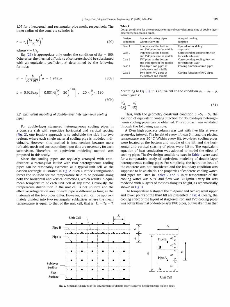
Table 1Design conditions for the comparative study of equivalent modeling of double-layerheterogeneous cooling pipes.
Designconditions
Layout of cooling pipeswithin every lift
Adopted coolingfunction
Case 1 Iron pipes at the bottomand PVC pipes in the middle
Equivalent modelingapproach
Case 2 Iron pipes at the bottomand PVC pipes in the middle
Corresponding cooling functionfor each sub-layer
Case 3 PVC pipes at the bottomand iron pipes in the middle
Corresponding cooling functionfor each sub-layer
Case 4 Two-layer iron pipes atthe bottom and middle
Cooling function of iron pipes
Case 5 Two-layer PVC pipes atthe bottom and middle
Cooling function of PVC pipes
J. Yang et al. / Applied Thermal Engineering 35 (2012) 145e156 149
1.07 for a hexagonal and rectangular pipe mesh, respectively. Theinner radius of the concrete cylinder is:
r ¼ r0
r0 � tp
r0
h
(29)
where h ¼ k/kp.Eq. (27) is appropriate only under the condition of R/r ¼ 100.
Otherwise, the thermal diffusivity of concrete should be substitutedwith an equivalent coefficient a0 determined by the followingformula:
a0 ¼
b0:7167
2
a ¼ 1:947ba (30a)
b ¼ 0:926exp�� 0:0314
Rr� 20
0:48�; 20 � R
r� 130
(30b)
3.2. Equivalent modeling of double-layer heterogeneous coolingpipes
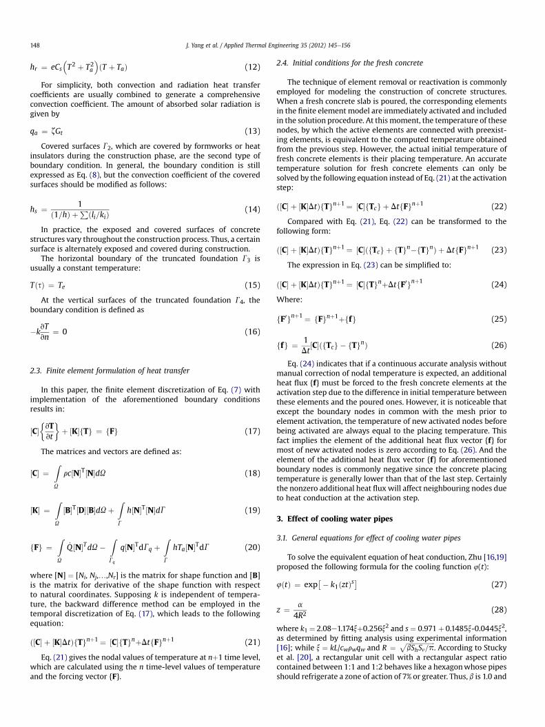
For double-layer staggered heterogeneous cooling pipes ina concrete slab with repetitive horizontal and vertical spacing(Fig. 2), one feasible approach is to subdivide the slab into tworegions, where each single material cooling pipe is modeled indi-vidually. However, this method is inconvenient because morerefinablemesh and corresponding input data are necessary for eachsubdivision. Therefore, an equivalent modeling method wasproposed in this study.
Since the cooling pipes are regularly arranged with equi-distance, a rectangular lattice with two heterogeneous coolingpipes can be reasonably extracted as a typical unit cell, as thedashed rectangle illustrated in Fig. 2. Such a lattice configurationforces the solution for the temperature field to be periodic alongboth the horizontal and vertical directions, which results in equalmean temperature of each unit cell at any time. Obviously, thetemperature distribution in the unit cell is not uniform and theeffective refrigeration area of each pipe is different as long as thematerials of the two pipes differ. However, it still can be approxi-mately divided into two rectangular sublattices where the meantemperature is equal to that of the unit cell, that is, TA ¼ TB ¼ T.
Fig. 2. Schematic diagram of the arrangement of dou
According to Eq. (3), it is equivalent to the condition 4A ¼ 4B ¼ 4,which yields:
a0A4R2A
¼ a0B4R2B
(31)
Thus, with the geometry constraint condition S1þS2 ¼ Sv, thesolution of equivalent cooling function for double-layer heteroge-neous cooling pipes can be obtained. This approach was validatedthrough the following example.
A 15-m high concrete column was cast with five lifts at everyseven-day interval. The height of every lift was 3 m and the placingtemperature was 20 �C. Within every lift, two-layer cooling pipeswere located at the bottom and middle of the lift, and the hori-zontal and vertical spacing of pipes were 1.5 m. The equivalentequation of heat conduction was adopted to model the effect ofcooling pipes. The five design conditions listed in Table 1 were usedfor a comparative study of equivalent modeling of double-layerheterogeneous cooling pipes. For simplicity, the hydration heat ofthe concrete was not considered and the boundary condition wassupposed to be adiabatic. The properties of concrete, cooling water,and pipes are listed in Tables 2 and 3. Inlet temperature of thecooling water was 5 �C and flow was 30 l/min. Every lift wasmodeled with 6 layers of meshes along its height, as schematicallyshown in Fig. 3.
The temperature history of the midpoint and two adjacent upperand lower points of the third lift are presented in Fig. 4. Clearly, thecooling effect of the layout of staggered iron and PVC cooling pipeswas better than that of double-layer PVC pipes, but weaker than that
ble-layer staggered heterogeneous cooling pipes.
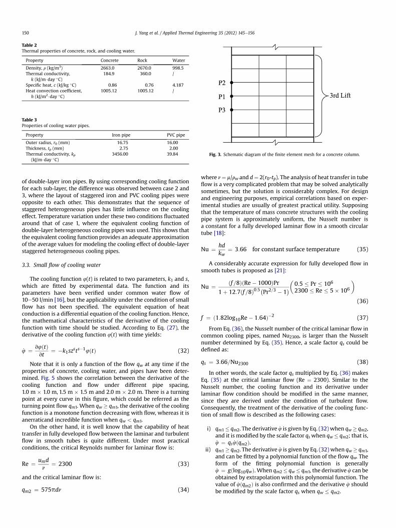
Table 2Thermal properties of concrete, rock, and cooling water.
Property Concrete Rock Water
Density, r (kg/m3) 2663.0 2670.0 998.5Thermal conductivity,
k (kJ/m$day �C)184.9 360.0 /
Specific heat, c (kJ/kg �C) 0.86 0.76 4.187Heat convection coefficient,
h (kJ/m2$day �C)1005.12 1005.12 /
Table 3Properties of cooling water pipes.
Property Iron pipe PVC pipe
Outer radius, r0 (mm) 16.75 16.00Thickness, tp (mm) 2.75 2.00Thermal conductivity, kp
(kJ/m$day �C)3456.00 39.84 Fig. 3. Schematic diagram of the finite element mesh for a concrete column.
J. Yang et al. / Applied Thermal Engineering 35 (2012) 145e156150
of double-layer iron pipes. By using corresponding cooling functionfor each sub-layer, the difference was observed between case 2 and3, where the layout of staggered iron and PVC cooling pipes wereopposite to each other. This demonstrates that the sequence ofstaggered heterogeneous pipes has little influence on the coolingeffect. Temperature variation under these two conditions fluctuatedaround that of case 1, where the equivalent cooling function ofdouble-layer heterogeneous cooling pipes was used. This shows thatthe equivalent cooling function provides an adequate approximationof the average values for modeling the cooling effect of double-layerstaggered heterogeneous cooling pipes.
3.3. Small flow of cooling water
The cooling function 4(t) is related to two parameters, k1 and s,which are fitted by experimental data. The function and itsparameters have been verified under common water flow of10e50 l/min [16], but the applicability under the condition of smallflow has not been specified. The equivalent equation of heatconduction is a differential equation of the cooling function. Hence,the mathematical characteristics of the derivative of the coolingfunction with time should be studied. According to Eq. (27), thederivative of the cooling function 4(t) with time yields:
_4 ¼ v4ðtÞvt
¼ �k1szsts�14ðtÞ (32)
Note that it is only a function of the flow qw at any time if theproperties of concrete, cooling water, and pipes have been deter-mined. Fig. 5 shows the correlation between the derivative of thecooling function and flow under different pipe spacing,1.0 m � 1.0 m, 1.5 m � 1.5 m and 2.0 m � 2.0 m. There is a turningpoint at every curve in this figure, which could be referred as theturning point flow qm1. When qw � qm1, the derivative of the coolingfunction is a monotone function decreasing with flow, whereas it isanerraticand incredible function when qw < qm1.
On the other hand, it is well know that the capability of heattransfer in fully developed flow between the laminar and turbulentflow in smooth tubes is quite different. Under most practicalconditions, the critical Reynolds number for laminar flow is:
Re ¼ umdn
¼ 2300 (33)
and the critical laminar flow is:
qm2 ¼ 575pdn (34)
where n¼ m/rw and d¼ 2(r0-tp). The analysis of heat transfer in tubeflow is a very complicated problem that may be solved analyticallysometimes, but the solution is considerably complex. For designand engineering purposes, empirical correlations based on exper-imental studies are usually of greatest practical utility. Supposingthat the temperature of mass concrete structures with the coolingpipe system is approximately uniform, the Nusselt number isa constant for a fully developed laminar flow in a smooth circulartube [18]:
Nu ¼ hdkw
¼ 3:66 for constant surface temperature (35)
A considerably accurate expression for fully developed flow insmooth tubes is proposed as [21]:
Nu ¼ ðf =8ÞðRe� 1000ÞPr1þ 12:7ðf =8Þ0:5 Pr2=3 � 1
�0:5 � Pr � 106
2300 � Re � 5� 106
(36)
f ¼ ð1:82log10Re� 1:64Þ�2 (37)
From Eq. (36), the Nusselt number of the critical laminar flow incommon cooling pipes, named Nu2300, is larger than the Nusseltnumber determined by Eq. (35). Hence, a scale factor qs could bedefined as:
qs ¼ 3:66=Nu2300 (38)
In other words, the scale factor qs multiplied by Eq. (36) makesEq. (35) at the critical laminar flow (Re ¼ 2300). Similar to theNusselt number, the cooling function and its derivative underlaminar flow condition should be modified in the same manner,since they are derived under the condition of turbulent flow.Consequently, the treatment of the derivative of the cooling func-tion of small flow is described as the following cases:
i) qm1� qm2. The derivative _4 is given by Eq. (32) when qw� qm2,and it is modified by the scale factor qswhen qw� qm2; that is,_4 ¼ qs _4ðqm2Þ.
ii) qm1� qm2. The derivative _4 is given by Eq. (32) when qw� qm1,and can be fitted by a polynomial function of the flow qw. Theform of the fitting polynomial function is generally_4 ¼ gðlog10qwÞ. When qm2� qw� qm1, the derivative _4 can beobtained by extrapolation with this polynomial function. Thevalue of _4ðqm2Þ is also confirmed and the derivative _4 shouldbe modified by the scale factor qs when qw � qm2.
14 21 28 35 428
12
16
20
Time (d)
Tem
pera
ture
(°C
)
Case 1Case 2Case 3Case 4Case 5
14 21 28 35 428
12
16
20
Time (d)
Tem
pera
ture
(°C
)
Case 1Case 2Case 3Case 4Case 5
a
b
c
14 21 28 35 428
12
16
20
Time (d)
Tem
pera
ture
(°C
)
Case 1Case 2Case 3Case 4Case 5
Fig. 4. Temperature variations of the third lift of the concrete column: (a) middle pointP1, (b) upper point P2, and (c) lower point P3.
Fig. 5. Correlation between derivative of the cooling function and the flow.
J. Yang et al. / Applied Thermal Engineering 35 (2012) 145e156 151
Since the cooling pipe embedded in concrete is long enough, thethermal entrance region where flow is not developed was neglec-ted in the analysis presented above.
4. Adiabatic temperature rise curve of concrete
The hydration heat of concrete is the main heat source in massconcrete structures, and is represented by _Q
þin Eq. (2). The adia-
batic temperature rise model is often used for the simulation of thehydration heat of concrete. One of the most widely used model forordinary concrete is given by [22,23]:
qðtÞ ¼ q0
�1� e�mt
�(39)
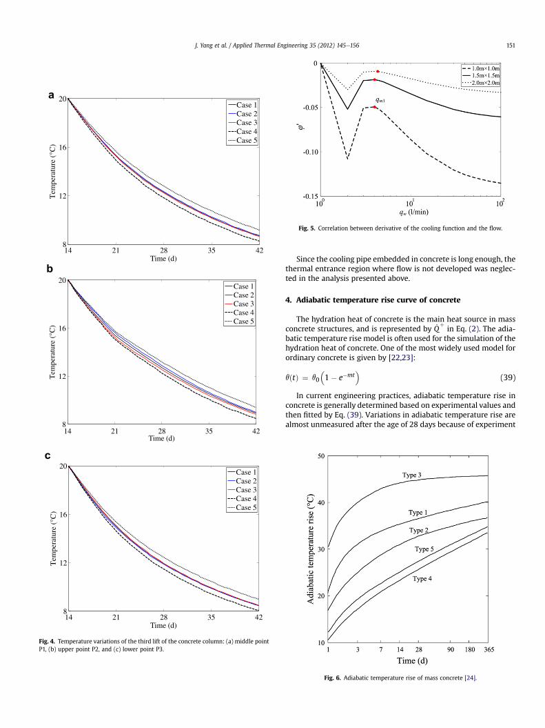
In current engineering practices, adiabatic temperature rise inconcrete is generally determined based on experimental values andthen fitted by Eq. (39). Variations in adiabatic temperature rise arealmost unmeasured after the age of 28 days because of experiment
Fig. 6. Adiabatic temperature rise of mass concrete [24].
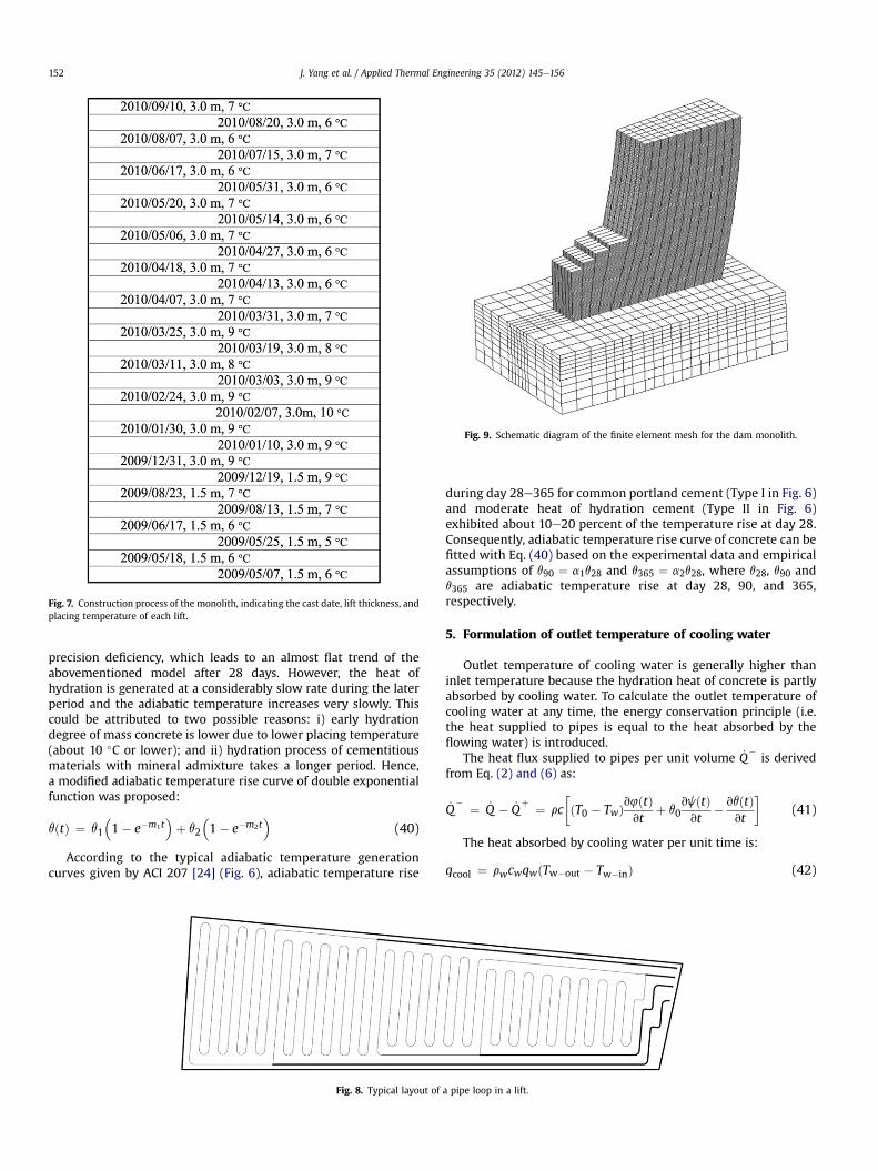
Fig. 7. Construction process of the monolith, indicating the cast date, lift thickness, andplacing temperature of each lift.
Fig. 9. Schematic diagram of the finite element mesh for the dam monolith.
J. Yang et al. / Applied Thermal Engineering 35 (2012) 145e156152
precision deficiency, which leads to an almost flat trend of theabovementioned model after 28 days. However, the heat ofhydration is generated at a considerably slow rate during the laterperiod and the adiabatic temperature increases very slowly. Thiscould be attributed to two possible reasons: i) early hydrationdegree of mass concrete is lower due to lower placing temperature(about 10 �C or lower); and ii) hydration process of cementitiousmaterials with mineral admixture takes a longer period. Hence,a modified adiabatic temperature rise curve of double exponentialfunction was proposed:
qðtÞ ¼ q1
�1� e�m1t
�þ q2
�1� e�m2t
�(40)
According to the typical adiabatic temperature generationcurves given by ACI 207 [24] (Fig. 6), adiabatic temperature rise
Fig. 8. Typical layout of
during day 28e365 for common portland cement (Type I in Fig. 6)and moderate heat of hydration cement (Type II in Fig. 6)exhibited about 10e20 percent of the temperature rise at day 28.Consequently, adiabatic temperature rise curve of concrete can befitted with Eq. (40) based on the experimental data and empiricalassumptions of q90 ¼ a1q28 and q365 ¼ a2q28, where q28, q90 andq365 are adiabatic temperature rise at day 28, 90, and 365,respectively.
5. Formulation of outlet temperature of cooling water
Outlet temperature of cooling water is generally higher thaninlet temperature because the hydration heat of concrete is partlyabsorbed by cooling water. To calculate the outlet temperature ofcooling water at any time, the energy conservation principle (i.e.the heat supplied to pipes is equal to the heat absorbed by theflowing water) is introduced.
The heat flux supplied to pipes per unit volume _Q�is derived
from Eq. (2) and (6) as:
_Q� ¼ _Q � _Q
þ ¼ rc�ðT0 � TwÞv4ðtÞ
vtþ q0
vjðtÞvt
� vqðtÞvt
�(41)
The heat absorbed by cooling water per unit time is:
qcool ¼ rwcwqwðTw�out � Tw�inÞ (42)
a pipe loop in a lift.
0 100 200 300 400 500 6000
5
10
15
20
25
30
Time (d)
Tem
pera
ture
(°C
)measured (thermometers)computed (double e-fun)computed (single e-fun)
100 200 300 400 500 6000
5
10
15
20
25
30
Time (d)
Tem
pera
ture
(°C
)
measured (thermometers)measured (optical fiber)computed (double e-fun)computed (single e-fun)
200 300 400 500 6000
5
10
15
20
25
30
Time (d)
Tem
pera
ture
(°C
)
measured (thermometers)measured (optical fiber)computed (double e-fun)computed (single e-fun)
300 400 500 6000
5
10
15
20
25
30
Time (d)
Tem
pera
ture
(°C
)
measured (thermometers)measured (optical fiber)computed (double e-fun)computed (single e-fun)
350 400 450 500 550 6000
5
10
15
20
25
30
Time (d)
Tem
pera
ture
(°C
)
measured (thermometers)measured (optical fiber)computed (double e-fun)computed (single e-fun)
350 400 450 500 550 6000
5
10
15
20
25
30
Time (d)
Tem
pera
ture
(°C
)
measured (thermometers)measured (optical fiber)computed (double e-fun)computed (single e-fun)
a b
c d
e f
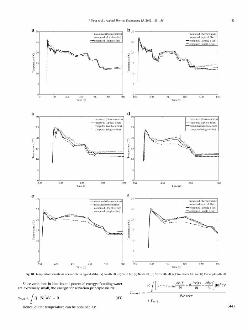
Fig. 10. Temperature variations of concrete in typical slabs: (a) Fourth lift, (b) Sixth lift, (c) Ninth lift, (d) Sixteenth lift, (e) Twentieth lift, and (f) Twenty-fourth lift.
J. Yang et al. / Applied Thermal Engineering 35 (2012) 145e156 153
Since variations in kinetics and potential energy of coolingwaterare extremely small, the energy conservation principle yields:
qcool þZV
_Q�½N�TdV ¼ 0 (43)
Hence, outlet temperature can be obtained as:
rc ðT0 � Tw�inÞv4ðtÞvt
þ q0vjðtÞvt
� vqðtÞvt
½N�TdV
Tw�out ¼ZV
� �
rwcwqwþ Tw�in
(44)

J. Yang et al. / Applied Thermal Engineering 35 (2012) 145e156154
6. Case study
6.1. Modeling of an arch dam monolith
A 286-m high parabolic double-curvature arch dam underconstruction is located in Southwest China at an altitude of 610 mabove sea level (level of crest). The dam consists of 31monoliths fora total crest length of 680 m. The crown cantilever has a crestthickness of 14 m and a base thickness of 60 m. One of themonoliths on the riverbed, which was started on May 7, 2009, wasselected for the thermal analysis in this study. To that date, stagenumber 30 had been completed and a height of 79.5 m had beenachieved. The progress of monolith construction to the 30th liftwith respect to time is shown in Fig. 7.
From 1st to 7th lift, therewas only one layer of iron cooling pipesarranged on the bottom of the slab. From the 8th to 18th lift, therewas a double-layer of heterogeneous cooling pipes, with iron pipesat the bottom and PVC pipes at the central elevation. Otherwise,there was a double-layer of PVC pipes in a slab. The typical layout ofa pipe loop is shown in Fig. 8, with horizontal and vertical spacingof 1.5 m. Thermometers and distributed optical fiber temperaturesystemwere embedded in every lift away from the pipes at a heightof about 0.5e1.0 m.
Fig. 9 shows the finite element mesh of the monolith. Thethickness of an element for the dam body was 0.5 m. When a freshconcrete slab was poured, the corresponding elements in the finiteelement model were immediately activated and included in thesolution.
6.2. Boundary conditions and initial conditions
The monolith gradually rose with the progress of construction.Increasing upstream and downstream surfaces of poured concreteslabs and the top surface of the latest slab were assumed to bedirectly exposed to the environment, where heat transfer byconvention and radiation occurred. Daily mean air temperature atthe dam site was used in this analysis. The effect of solar radiationwas simply taken into account through increasing ambienttemperature by 2 �C [8].
Since the construction of the selected monolith was alwaysbehind that of adjacent monoliths, the boundary condition of bothsides was assumed to be adiabatic.
Supposing that the initial temperatures of all the nodes of thefoundation were all equal to annual mean air temperature, heattransfer between the environment and the foundation over a yearwas analyzed. Thus, the temperature distribution in the foundationwas obtained.
Fig. 11. Comparison of the effects of scale factor qs for small flow.
6.3. Properties of materials
The thermal properties of placed concrete and rock aresummarized in Table 2. In order to investigate the effect of thecooling pipe, the thermal properties of cooling water and coolingpipes (Table 2 and Table 3, respectively) were used. During pipecooling, inlet temperatures varied within the range of 8e20 �C,whereas the flow of cooling water was within 1e50 l/min. Dailymean values of inlet temperature and flow were used in thenumerical analysis. The scale factor qs when there was small flow ofcooling water was 0.21.
Fitting analysis with Eq. (39) based on experimental data yiel-ded parameters q0 ¼ 26.0 �C and m ¼ 0.25 day�1. Assumingq90 ¼ a1q28 and q365 ¼ a2q28, where a1 and a2 were 1.1 and 1.2,respectively, the fitting analysis with Eq. (40) resulted inq1 ¼ 25.3 �C, q2 ¼ 6.2 �C, m1 ¼ 0.26 day�1, and m2 ¼ 0.0085 day�1.
6.4. Results and discussions
The comparison of temperature histories of concrete betweencalculated results and actual measured temperature from ther-mometers and optical fibers in the six typical slabs are presented inFig. 10. Overall calculated results obtained from the proceduredeveloped in this studywere in good agreement with themeasureddata. Maximum peak temperatures at early age were accuratelycaptured by the developed code in most lifts, and the discrepancybetween calculated and measured data did not exceed 1 �C.
The trend of predicted temperature variations in slabs wheredouble-layer heterogeneous cooling pipes were used coincidedwith the actual trends observed (Fig.10(c) and (d)), thereby provingthe rationality of equivalent modeling of double-layer heteroge-neous cooling pipes. Calculated results were slightly lower thanmeasured data most of the time because the equivalent modelingapproach did not include the effect of sequence of staggeredheterogeneous pipes, as already explained earlier.
Obviously, temperature recovery in concrete was observed atlate ages (at least two months after casting), when the slabhas been covered by newer lifts. The internal temperature of theslab was almost independent of environmental influence.Consequently, the phenomenon of temperature recovery wasattributed to internal heat generation by concrete. Fig. 10 showsthat temperature recovery was reproduced perfectly usingthe adiabatic temperature rise curve of a double exponentialfunction to consider heat hydration of other cementitiousmaterials at late age. Otherwise, conventional adiabatic temper-ature rise model with a single exponential function had worseperformance.
The 20th lift, which experienced a long time of laminar flow,was selected for the investigation of the effect of scale factor qs forsmall flow. We considered three situations: no effect, modifiedeffect, and full effect, corresponding to qs of 0.0, 0.21, and 1.0respectively. Fig. 11 illustrates the comparison of temperaturevariations of concrete. Predicted temperature considering themodified effect with qs ¼ 0.21 was concurred with measured data,whereas that of no effect was higher and that of full effect waslower than actual values. Thus, modification of cooling effect underlaminar flow condition is necessary, and the approach presentedhere is appropriate.
Variations in outlet and inlet temperature of cooling pipes andin flow of cooling water in six typical slabs are presented in Fig. 12.Results indicate that the temperature increase of cooling water was
5
10
15
20
25
Time (d)
Tem
pera
ture
(°C
)
10
20
30
40
50
0
350 400 450 500 550 600
Flow
(l/m
in)
flow (measured)inlet (measured)outlet (measured)outlet (numerical)
350 400 450 500 550 6005
10
15
20
25
Time (d)
Tem
pera
ture
(°C
)
0
10
20
30
40
50
Flow
(l/m
in)
flow (measured)inlet (measured)outlet (measured)outlet (numerical)
e f
250 300 350 400 450 5005
10
15
20
25
Time (d)
Tem
pera
ture
(°C
)
0
10
20
30
40
50
Flow
(l/m
in)
flow (measured)inlet (measured)outlet (measured)outlet (numerical)
300 400 450 500 5505
10
15
20
25
Time (d)
Tem
pera
ture
(°C
)
10
20
30
40
50
60
350
0
Flow
(l/m
in)
flow (measured)inlet (measured)outlet (measured)outlet (numerical)
c d
a b
5
10
15
20
25
Time (d)
Tem
pera
ture
(°C
)
0 100 200 300 400 500
0
10
20
30
40
50
60
Flow
(l/m
in)
flow (measured)inlet (measured)outlet (measured)outlet (numerical)
100 200 300 400 5005
10
15
20
25
Time (d)
Tem
pera
ture
(°C
)
60
50
0
10
20
30
40
Flow
(l/m
in)
flow (measured)inlet (measured)outlet (measured)outlet (numerical)
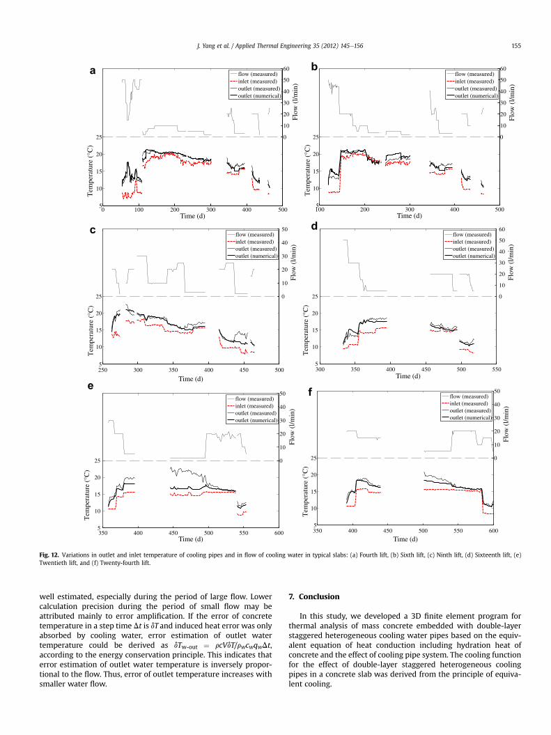
Fig. 12. Variations in outlet and inlet temperature of cooling pipes and in flow of cooling water in typical slabs: (a) Fourth lift, (b) Sixth lift, (c) Ninth lift, (d) Sixteenth lift, (e)Twentieth lift, and (f) Twenty-fourth lift.
J. Yang et al. / Applied Thermal Engineering 35 (2012) 145e156 155
well estimated, especially during the period of large flow. Lowercalculation precision during the period of small flow may beattributed mainly to error amplification. If the error of concretetemperature in a step time Dt is dT and induced heat error was onlyabsorbed by cooling water, error estimation of outlet watertemperature could be derived as dTw-out ¼ rcVdT/rwcwqwDt,according to the energy conservation principle. This indicates thaterror estimation of outlet water temperature is inversely propor-tional to the flow. Thus, error of outlet temperature increases withsmaller water flow.
7. Conclusion
In this study, we developed a 3D finite element program forthermal analysis of mass concrete embedded with double-layerstaggered heterogeneous cooling water pipes based on the equiv-alent equation of heat conduction including hydration heat ofconcrete and the effect of cooling pipe system. The cooling functionfor the effect of double-layer staggered heterogeneous coolingpipes in a concrete slab was derived from the principle of equiva-lent cooling.

J. Yang et al. / Applied Thermal Engineering 35 (2012) 145e156156
According to forced-convention heat transfer of internal flow,the cooling effect under laminar flow condition using equivalentheat conduction equation was proposed to be modified by a scalefactor qs. Monotonicity of the derivative of the cooling functionwithtime was discussed in detail to improve the applicability andprecision of the equivalent heat conduction equation under smallflow. Considering heat hydration of concrete at late age, a doubleexponential functionwas presented to fit the adiabatic temperaturerise curve of concrete. Once temperature variation of concrete wasobtained, the energy conservation principle was implemented toestimate the outlet temperature of cooling water.
We verified the reliability, precision and efficiency of thedeveloped 3D finite element program by comparing the calculatedresults and actual measured temperature of a dam monolith witha cooling pipe system. Outlet temperature of cooling water wasefficiently obtained by the model. Findings of this study demon-strate that the developed program can be applied in the thermalanalysis of mass concrete structures with an embedded pipe cool-ing system during the design and construction phase.
Acknowledgements
This research was supported by National Natural ScienceFoundation of China (No.50539020).
References
[1] A.M. Neville, Properties of Concrete. Longman, Essex, England, 1995.[2] D.C. Lawrence, Physiochemical and mechanical properties of portland cement.
in: P.C. Hewlett (Ed.), LEA’S Chemistry of Cement Concrete. Butterworth andHeinemann, Oxford, England, 1998, pp. 343e420.
[3] American Concrete Institute, Cooling and Insulating Systems for MassConcrete (ACI 207.4R-05) (2005).
[4] US Bureau of Reclamation. The Story of Hoover Dam. http://www.usbr.gov/lc/hooverdam/History/essays/concrete.html.
[5] G. Hauser, C. Kempkes, B.W. Olesen, Computer simulation of hydronic heat-ing/cooling system with embedded pipes, ASHRAE Transactions 106 (2000)702e710.
[6] R.E. Glover, Cooling of Concrete Dams. Final reports for Boulder Canyon Project.United States Department of the Interior, Bureau of Reclamation, Denver, 1949.
[7] B.F. Zhu, Calculation of temperatures in mass concrete with internal source ofheat, cooled by embedded pipes, Chinese Journal of Hydraulic Engineering 4(1957) 87e106 (in Chinese).
[8] The Ministry of Water Resources of the People’s Republic of China, DesignSpecification for Concrete Arch Dam. China WaterPower Press, Beijing, 2003,(in Chinese).
[9] C. Liu, Temperature field of mass concrete in pipe lattice, Journal of Materialsin Civil Engineering 16 (5) (2004) 427e432.
[10] J.P.F. Charpin, T.G. Myers, A.D. Fitt, N.D. Fowkes, D.P. Mason, Piped watercooling of concrete dams, in: Proceedings of the 1st South African Mathe-matics in Industry Study Group. Univ. of the Witwatersrand, Johannesburg,South Africa, 2004, pp. 69e86.
[11] T.G. Myers, N.D. Fowkes, Y. Ballim, Modeling the cooling of concrete by pipedwater, Journal of Engineering Mechanics 135 (12) (2009) 1375e1383.
[12] B.F. Zhu, J.B. Cai, Finite element analysis of effect of pipe cooling in concretedams, Journal of Construction Engineering and Management 115 (4) (1989)487e498.
[13] J.K. Kim, K.H. Kim, J.K. Yang, Thermal analysis of hydration heat in concretestructures with pipe-cooling system, Computers and Structures 79 (2) (2001)163e171.
[14] H. Kawaraba, T. Kanokogi, T. Tanabe, Development of the FEM program forthe analysis of pipe cooling effects on the thermal stress of massiveconcrete, Transaction of Japanese Concrete Institute 8 (1986) 45e48 (inJapanese).
[15] M.S. Roberta, Finite Element Modeling of Cooling Coil Effects in Mass ConcreteSystems (final report), ERDC/ITL TR-01e3. US Army Corps of Engineers, St.Louis, 2001.
[16] B.F. Zhu, Equivalent equation of heat conduction in mass concrete consideringthe effect of pipe cooling, Chinese Journal of Hydraulic Engineering 3 (1991)28e34 (in Chinese).
[17] H.W. Xie, Y.L. Chen, Influence of the different pipe cooling scheme ontemperature distribution in RCC arch dams, Communication in NumericalMethods in Engineering 21 (12) (2005) 769e778.
[18] Y.A. Cengel, Heat and Mass Transfer: A Practical Approach, third ed.McGraw-Hill, Boston, 2007.
[19] B.F. Zhu, Effect of cooling by water flowing in nonmetal pipes embedded inmass concrete, Journal of Construction Engineering and Management 125 (1)(1997) 61e68.
[20] A. Stucky, M. Derron, Problèmes thermiques posés par la construction desbarrages-réservoirs EPFL publication no 38. Editions Sciences and Techique,Paul Feissly éditeur, Lausanne, 1957.
[21] Adrian Bejan, Allan D. Kraus, Heat Transfer Handbook. John Wiley & Sons, Inc.,Hoboken, New Jersey, 2003.
[22] Japan Concrete Institute, Standard Specifications for Design and Constructionof Concrete Structures, Part 2 (Construction) Tokyo (1986).
[23] M. Ishikawa, Thermal stress analysis of a concrete dam, Computers andStructures 40 (2) (1991) 347e352.
[24] American Concrete Institute, Mass Concrete (ACI 207.1R-96) (1996).