Embed Size (px)
Citation preview
7/26/2019 Theory Pump
http://slidepdf.com/reader/full/theory-pump 1/7
TITLE
Centrifugal Pump Performance Characteristic
INTRODUCTION
Centrifugal pump is one of the most common radial-flow turbo machines. A centrifugal
pump is a rotordynamic pump that uses a rotating impeller to increase the velocity of a
fluid. A centrifugal pump works by the conversion of the rotational kinetic energy,
typically from an electric motor or turbine, to an increased static fluid pressure. This
action is described by Bernoulli's principle. Centrifugal pumps are commonly used to
move liquids through a piping system. The fluid enters the pump impeller along or near
to the rotating axis and is accelerated by the impeller, flowing radially outward into adiffuser or volute chamber, from where it exits into the downstream piping system.
Centrifugal pumps are used for large discharge through smaller heads. Centrifugal pumps
basically consist of a stationary pump casing and an impeller mounted on a rotating shaft.
The pump casing provides a pressure boundary for the pump and contains channels to
properly direct the suction and discharge flow. The pump casing has suction and
discharge penetrations for the main flow path of the pump and normally has small drain
and vent fittings to remove gases trapped in the pump casing or to drain the pump casing
for maintenance.
The diagram shows a typical centrifugal pump that with the relative locations of the
pump suction, impeller, volute, and discharge. The centrifugal pump casing guides the
liquid from the suction connection to the center, or eye, of the impeller. The vanes of the
rotating impeller impart a radial and rotary motion to the liquid, forcing it to the outer
periphery of the pump casing where it is collected in the outer part of the pump casing
called the volute. The volute is a region that expands in cross-sectional area as it wraps
around the pump casing. The purpose of the volute is to collect the liquid discharged
from the periphery of the impeller at high velocity and gradually cause a reduction in
fluid velocity by increasing the flow area. This converts the velocity head to static
pressure. The fluid is then discharged from the centrifugal pump through the discharge
connection.
7/26/2019 Theory Pump
http://slidepdf.com/reader/full/theory-pump 2/7
Figure 1 : Basic elements of a Centrifugal Pumps
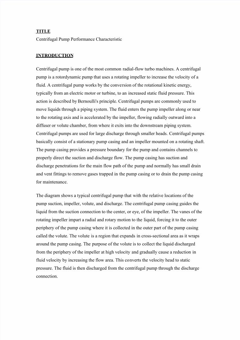
Centrifugal pumps can also be constructed in a manner that results in two distinct volutes,each receiving the liquid that is discharged from a 180 degrees region of the impeller at
any given time. Pumps of this type are called double volute pumps where they may also
be referred to as split volute pumps. In some applications the double volute minimizes
radial forces imparted to the shaft and bearings due to imbalances in the pressure around
the impeller. A comparison of single and double volute centrifugal pumps is shown
below.
Figure 2 : Types of centrifugal pump
7/26/2019 Theory Pump
http://slidepdf.com/reader/full/theory-pump 3/7
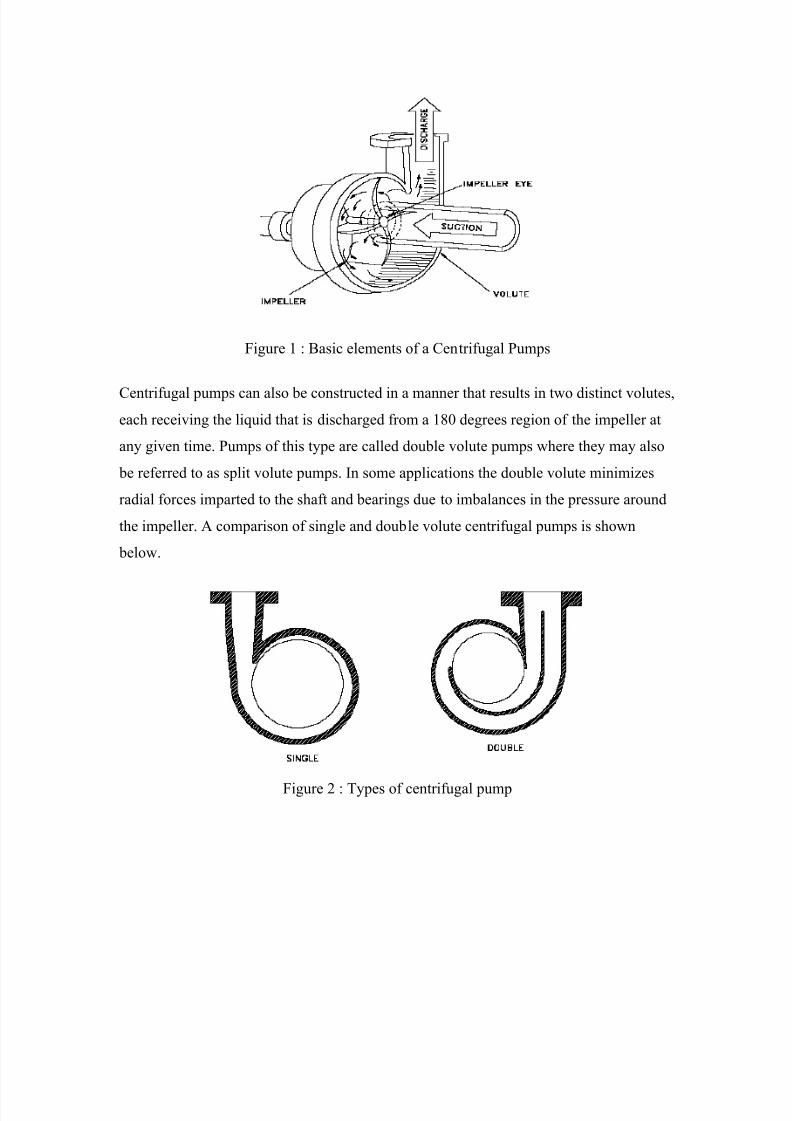
Figure 3 : Centrifugal pump
OBJECTIVE
To obtain performance characteristics for a variable speed centrifugal pump operating at
3 different impeller speeds. Performance characteristics of pump are pressure (head)
jump, power requirement, flow rate influence, and pump speed influence.
THEORY
Performance Characteristics
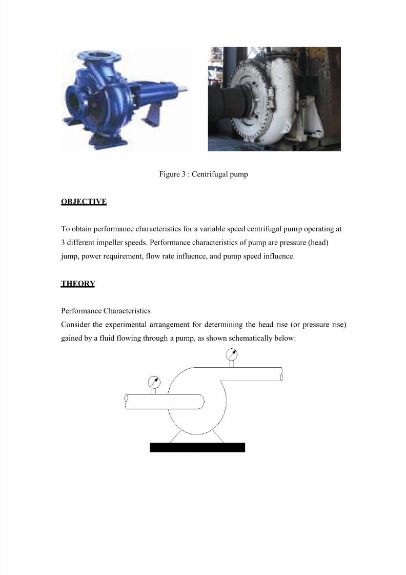
Consider the experimental arrangement for determining the head rise (or pressure rise)
gained by a fluid flowing through a pump, as shown schematically below:
7/26/2019 Theory Pump
http://slidepdf.com/reader/full/theory-pump 4/7
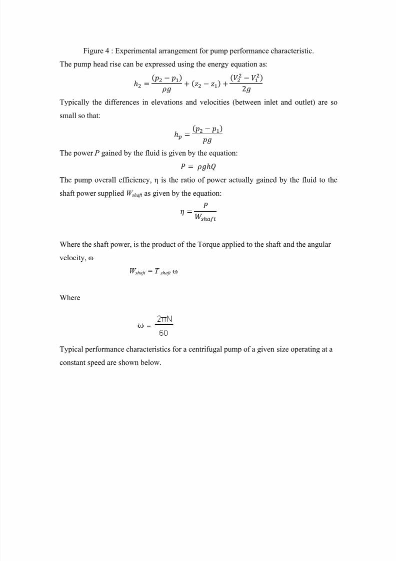
Figure 4 : Experimental arrangement for pump performance characteristic.
The pump head rise can be expressed using the energy equation as:
( )( )
( )
Typically the differences in elevations and velocities (between inlet and outlet) are so
small so that:
( )
The power P gained by the fluid is given by the equation:
The pump overall efficiency, η is the ratio of power actually gained by the fluid to the
shaft power supplied W shaft as given by the equation:
Where the shaft power, is the product of the Torque applied to the shaft and the angular
velocity, ω
W shaft = T shaft ω
Where
Typical performance characteristics for a centrifugal pump of a given size operating at a
constant speed are shown below.
7/26/2019 Theory Pump
http://slidepdf.com/reader/full/theory-pump 5/7
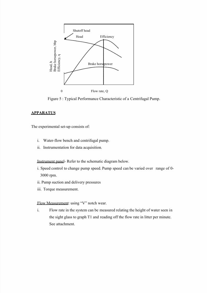
Figure 5 : Typical Performance Characteristic of a Centrifugal Pump.
APPARATUS
The experimental set-up consists of:
i. Water-flow bench and centrifugal pump.
ii. Instrumentation for data acquisition.
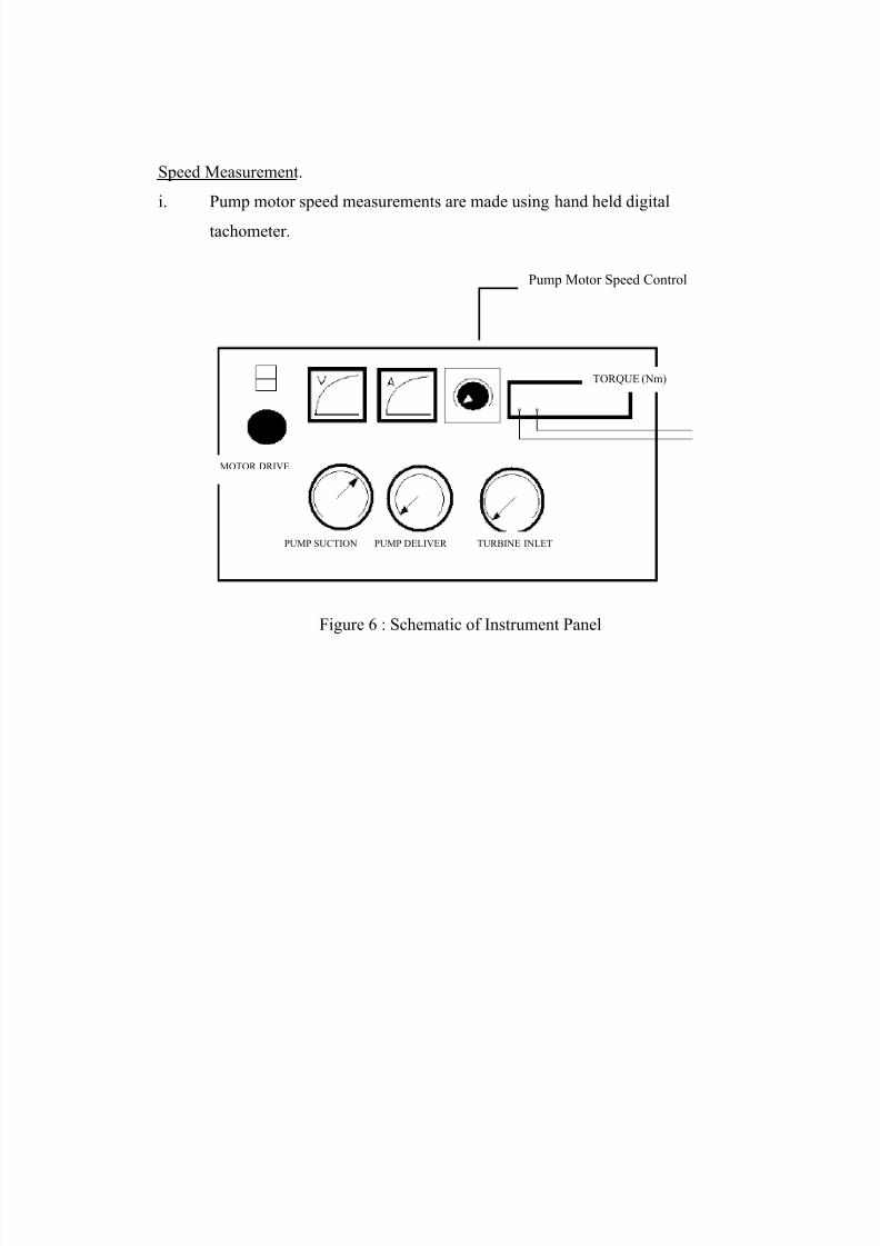
Instrument panel- Refer to the schematic diagram below.
i. Speed control to change pump speed. Pump speed can be varied over range of 0-
3000 rpm.
ii. Pump suction and delivery pressures
iii. Torque measurement.
Flow Measurement : using “V” notch wear.
i. Flow rate in the system can be measured relating the height of water seen in
the sight glass to graph T1 and reading off the flow rate in litter per minute.
See attachment.
Brake horsepower
Head
Shutoff head
Efficiency
H e a d ,
h
B r a k e
h o r s e p o w
e r , b h p
E f f i c i e n c y ,
η
Flow rate, Q0
7/26/2019 Theory Pump
http://slidepdf.com/reader/full/theory-pump 6/7
Speed Measurement.
i. Pump motor speed measurements are made using hand held digital
tachometer.
Pump Motor Speed Control
MOTOR DRIVE
PUMP SUCTION PUMP DELIVER
TORQUE (Nm)
TURBINE INLET
Figure 6 : Schematic of Instrument Panel
7/26/2019 Theory Pump
http://slidepdf.com/reader/full/theory-pump 7/7
EXPERIMENTAL PROCEDURE
Preliminaries
1. Students were adequately supervised by the lecturer and technician.
2. Pump discharge and suction valves were fully opened and the motor speed was
controlled to zero.
3. The electrical supply and motor drive were switched on. Motor control knob was
adjusted slowly to around half way position. No leaks were found in the system.
All gauges were checked and motor speed was reduced to zero.
Actual experiment
1. The suction valve was opened and the discharge valve was closed. Minimum
pump speed N 1 was selected by adjusting speed control to 50%. The speed of
pump in rpm was measured by using tachometer.
2. The discharge valve was fully opened and water allowed circulating. The
increments in flow were decided about eight points between zero and maximum
flow.
3. The discharge valve was closed (corresponding to no flow). All measurements
were read when the measured readings are steady.
4. The discharge valve was opened slightly for the first increment in volume flow.
Measurements were taken when readings are steady.
5. Step (4) was repeated. The valve was fully opened correspond to final
measurements. The entire experiment was repeated for the speed control position
of 75% and 90%. Furthermore, 10 readings were taken as opposed to 8 readings
in the first speed.