Embed Size (px)
Citation preview
Theoritical Limits of ISO/IEC 14443 type A
Eavesdropping Attacks
Florian Pfeiffer (perisens)
Klaus Finkenzeller (Giesecke & Devrient)
Erwin Biebl (Fachgebiet Höchstfrequenztechnik – TUM)
12.06.2012
Florian Pfeiffer & Klaus Finkenzeller
12.06.2012 Page 2
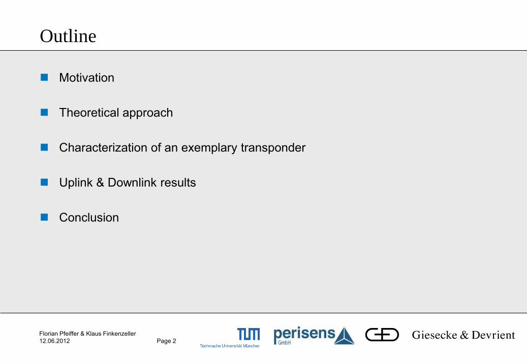
Outline
Motivation
Theoretical approach
Characterization of an exemplary transponder
Uplink & Downlink results
Conclusion
Florian Pfeiffer & Klaus Finkenzeller
12.06.2012 Page 3
Contactless smartcard PICC
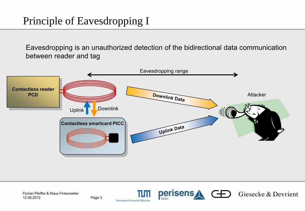
Eavesdropping is an unauthorized detection of the bidirectional data communication
between reader and tag
Principle of Eavesdropping I
Contactless reader
PCD
Downlink Uplink
Attacker
Eavesdropping range
Florian Pfeiffer & Klaus Finkenzeller
12.06.2012 Page 4
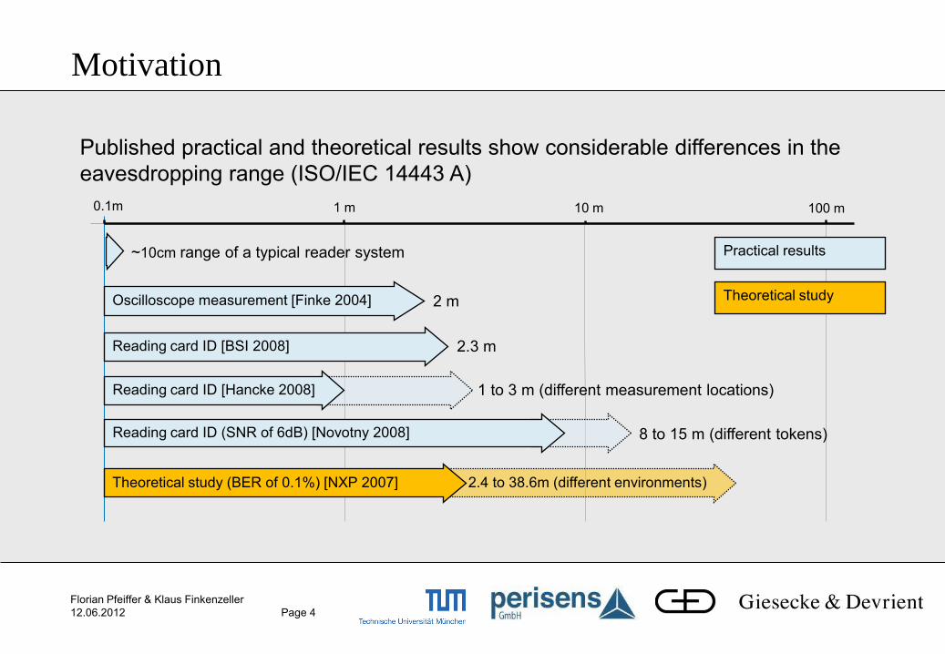
Motivation
0.1m 1 m
Oscilloscope measurement [Finke 2004]
Reading card ID [BSI 2008]
10 m 100 m
2 m
2.3 m
1 to 3 m (different measurement locations)
8 to 15 m (different tokens)
~10cm range of a typical reader system
2.4 to 38.6m (different environments) Theoretical study (BER of 0.1%) [NXP 2007]
Reading card ID (SNR of 6dB) [Novotny 2008]
Published practical and theoretical results show considerable differences in the
eavesdropping range (ISO/IEC 14443 A)
Reading card ID [Hancke 2008]
Practical results
Theoretical study
Florian Pfeiffer & Klaus Finkenzeller
12.06.2012 Page 5
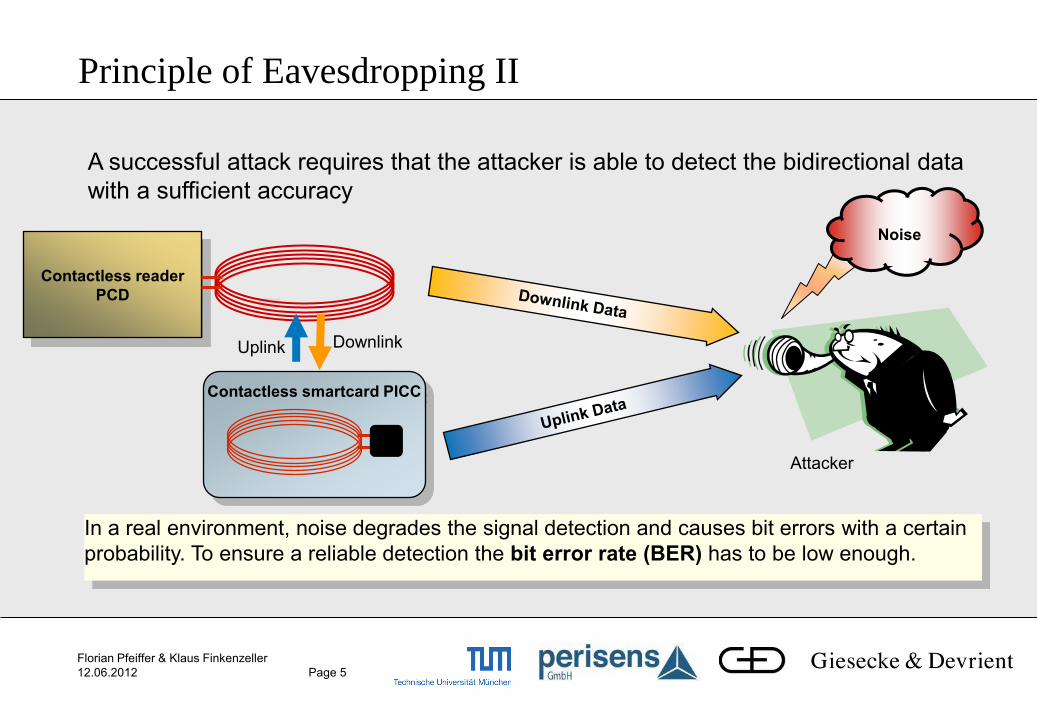
A successful attack requires that the attacker is able to detect the bidirectional data
with a sufficient accuracy
Principle of Eavesdropping II
Noise
In a real environment, noise degrades the signal detection and causes bit errors with a certain
probability. To ensure a reliable detection the bit error rate (BER) has to be low enough.
Contactless smartcard PICC
Contactless reader
PCD
Downlink Uplink
Attacker
Florian Pfeiffer & Klaus Finkenzeller
12.06.2012 Page 6
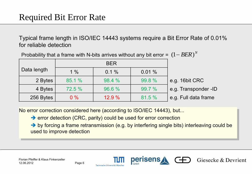
Required Bit Error Rate
Typical frame length in ISO/IEC 14443 systems require a Bit Error Rate of 0.01%
for reliable detection
Data length
BER
1 % 0.1 % 0.01 %
2 Bytes 85.1 % 98.4 % 99.8 % e.g. 16bit CRC
4 Bytes 72.5 % 96.6 % 99.7 % e.g. Transponder -ID
256 Bytes 0 % 12.9 % 81.5 % e.g. Full data frame
No error correction considered here (according to ISO/IEC 14443), but...
error detection (CRC, parity) could be used for error correction
by forcing a frame retransmission (e.g. by interfering single bits) interleaving could be
used to improve detection
Probability that a frame with N-bits arrives without any bit error = NBER)1(

Florian Pfeiffer & Klaus Finkenzeller
12.06.2012 Page 7
A reliable eavesdropping with a defined bit error rate (BER) requires a certain
signal-to-noise ratio (SNR)
Bit Error Rate as Function of the SNR
BER = 0.01% SNR = 11.4dB
BER = 0.1% SNR = 9.8dB
(BER = 2 % SNR = 6dB)
ISO/IEC 14443 A
Amplitude Shift Keying (ASK)
Additive white Gaussian noise
Coherent demodulation
Matched filter
optimum threshold detector
HFSNRBER
2
1erf
2
1
Florian Pfeiffer & Klaus Finkenzeller
12.06.2012 Page 8
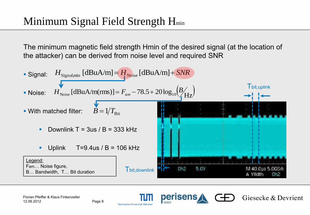
Minimum Signal Field Strength Hmin
The minimum magnetic field strength Hmin of the desired signal (at the location of
the attacker) can be derived from noise level and required SNR
Signal:
Noise:
With matched filter:
Downlink T = 3us / B = 333 kHz
Uplink T=9.4us / B = 106 kHz
SNRHH [dBuA/m] [dBuA/m] NoiseminSignal,
Hz
log205.78s)][dBuA/m(rm 10NoiseBFH am
Bit1 TB
Tbit,downlink
Tbit,uplink
Legend:
Fam… Noise figure,
B… Bandwidth, T… Bit duration

Florian Pfeiffer & Klaus Finkenzeller
12.06.2012 Page 9
In the HF-band the external noise normally exceeds the internal receiver noise
Noise Level in the HF-Band
External noise sources:
Man Made Noise (MMN) for
Business,
Residential,
Rural and quite rural environment
Atmospheric noise
Galactic noise
13.56 MHz
Assuming a non-directional antenna the noise
figure lies between:
26 dB for galactic noise and
45.4 dB for MMN in a business environment
[erc99]: European Radiocommunications Committee (ERC): Propagation Model and Interference Range Calculation for Inductive Systems 10 kHz – 30 MHz.
ERC report 69, 1999.
Florian Pfeiffer & Klaus Finkenzeller
12.06.2012 Page 10
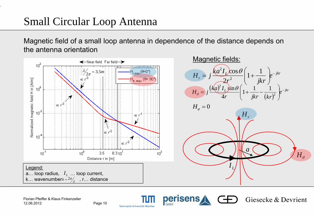
Magnetic field of a small loop antenna in dependence of the distance depends on
the antenna orientation
jkrL ekrjkrr
IkajH
2
211
14
sin
jkrLr e
jkrr
IkajH
11
2
cos2
2
Small Circular Loop Antenna
.
0H
Magnetic fields:
H
rH
LI
a
Legend:
a… loop radius, … loop current,
k… wavenumber , r… distance LI
2k
m5.32
Florian Pfeiffer & Klaus Finkenzeller
12.06.2012 Page 11
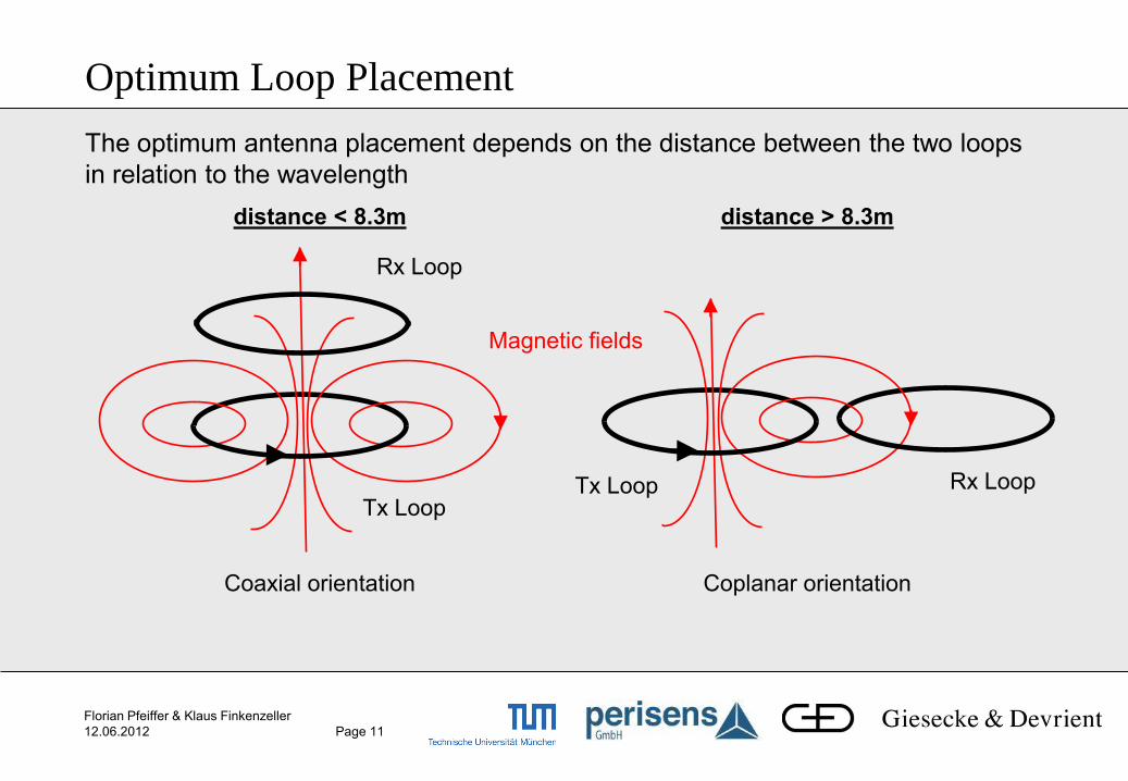
The optimum antenna placement depends on the distance between the two loops
in relation to the wavelength
Optimum Loop Placement
distance < 8.3m
Coaxial orientation
distance > 8.3m
Coplanar orientation
Tx Loop
Rx Loop
Tx Loop Rx Loop
Magnetic fields
Florian Pfeiffer & Klaus Finkenzeller
12.06.2012 Page 12
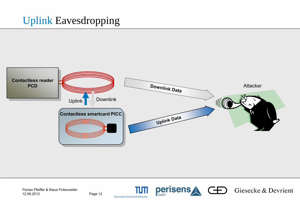
Contactless smartcard PICC
Uplink Eavesdropping
Contactless reader
PCD
Downlink Uplink
Attacker
Florian Pfeiffer & Klaus Finkenzeller
12.06.2012 Page 13
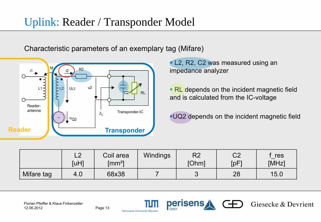
Uplink: Reader / Transponder Model
L2, R2, C2 was measured using an
impedance analyzer
RL depends on the incident magnetic field
and is calculated from the IC-voltage
UQ2 depends on the incident magnetic field
Transponder Reader
L2
[uH]
Coil area
[mm²]
Windings R2
[Ohm]
C2
[pF]
f_res
[MHz]
Mifare tag 4.0 68x38 7 3 28 15.0
Characteristic parameters of an exemplary tag (Mifare)
Florian Pfeiffer & Klaus Finkenzeller
12.06.2012 Page 14
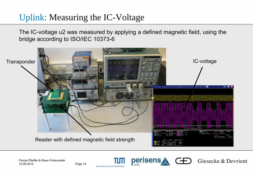
Uplink: Measuring the IC-Voltage
Reader with defined magnetic field strength
Transponder IC-voltage
The IC-voltage u2 was measured by applying a defined magnetic field, using the
bridge according to ISO/IEC 10373-6
Florian Pfeiffer & Klaus Finkenzeller
12.06.2012 Page 15
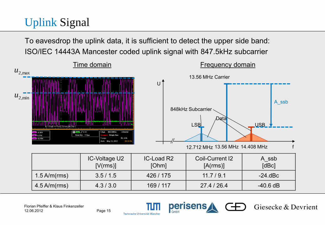
Time domain
Uplink Signal
Frequency domain
IC-Voltage U2
[V(rms)]
IC-Load R2
[Ohm]
Coil-Current I2
[A(rms)]
A_ssb
[dBc]
1.5 A/m(rms) 3.5 / 1.5 426 / 175 11.7 / 9.1 -24.dBc
4.5 A/m(rms) 4.3 / 3.0 169 / 117 27.4 / 26.4 -40.6 dB
U
f 13.56 MHz 12.712 MHz 14.408 MHz
13.56 MHz Carrier
848kHz Subcarrier
Data
USB LSB
A_ssb
max2,u
min2,u
To eavesdrop the uplink data, it is sufficient to detect the upper side band:
ISO/IEC 14443A Mancester coded uplink signal with 847.5kHz subcarrier
Florian Pfeiffer & Klaus Finkenzeller
12.06.2012 Page 16
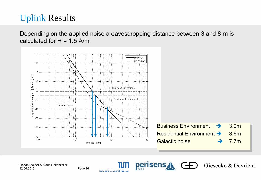
Depending on the applied noise a eavesdropping distance between 3 and 8 m is
calculated for H = 1.5 A/m
Uplink Results
Business Environment 3.0m
Residential Environment 3.6m
Galactic noise 7.7m

Florian Pfeiffer & Klaus Finkenzeller
12.06.2012 Page 17
Uplink Results (Coherent Demodulation)
Noise Source
Business Residential Galactic
BER =0.1%
1.5 A/m(rms) 3.2 m 3.9 m 9.4 m
4.5 A/m(rms) 2.2 m 2.7 m 5.5 m
BER=0.01%
1.5 A/m(rms) 3.0 m 3.6 m 7.7 m
4.5 A/m(rms) 2.1 m 2.5 m 5.1 m
Eavesdropping range lies between
2.2 and 9.4 m for BER of 0.1%
2.1 and 7.7 m for BER of 0.01%
With un-coherent demodulation the range decreases by 15 %
Maximum Eavesdropping distance depending on the BER, applied noise and field
strength
Florian Pfeiffer & Klaus Finkenzeller
12.06.2012 Page 18
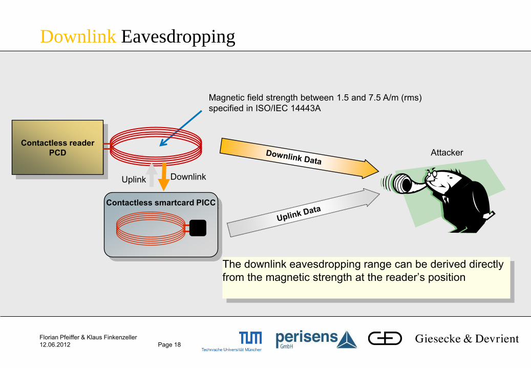
Contactless smartcard PICC
Downlink Eavesdropping
Magnetic field strength between 1.5 and 7.5 A/m (rms)
specified in ISO/IEC 14443A
The downlink eavesdropping range can be derived directly
from the magnetic strength at the reader’s position
Contactless reader
PCD
Downlink Uplink
Attacker
Florian Pfeiffer & Klaus Finkenzeller
12.06.2012 Page 19
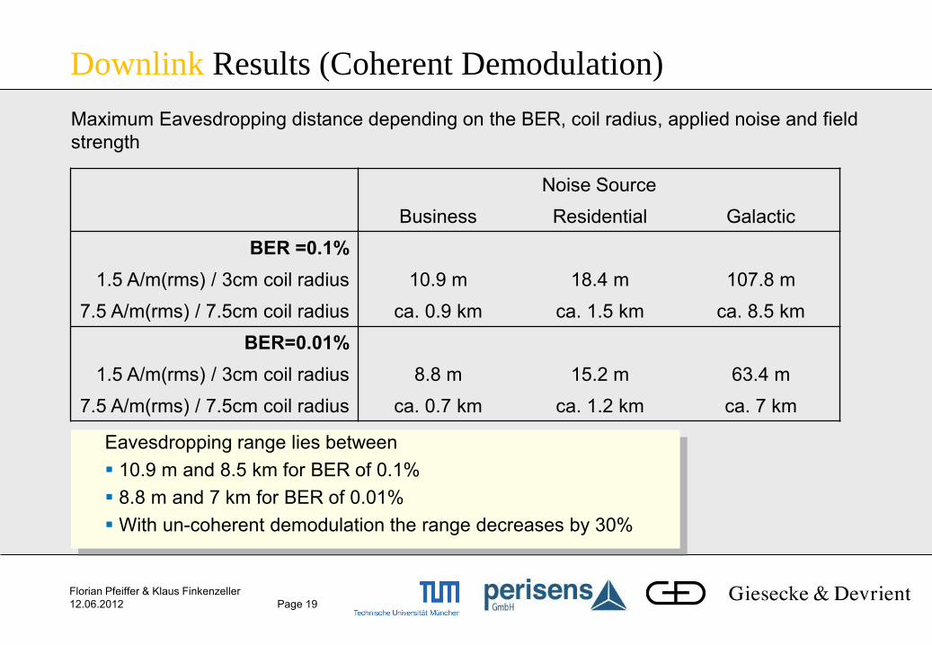
Downlink Results (Coherent Demodulation)
Noise Source
Business Residential Galactic
BER =0.1%
1.5 A/m(rms) / 3cm coil radius 10.9 m 18.4 m 107.8 m
7.5 A/m(rms) / 7.5cm coil radius ca. 0.9 km ca. 1.5 km ca. 8.5 km
BER=0.01%
1.5 A/m(rms) / 3cm coil radius 8.8 m 15.2 m 63.4 m
7.5 A/m(rms) / 7.5cm coil radius ca. 0.7 km ca. 1.2 km ca. 7 km
Eavesdropping range lies between
10.9 m and 8.5 km for BER of 0.1%
8.8 m and 7 km for BER of 0.01%
With un-coherent demodulation the range decreases by 30%
Maximum Eavesdropping distance depending on the BER, coil radius, applied noise and field
strength
Florian Pfeiffer & Klaus Finkenzeller
12.06.2012 Page 20
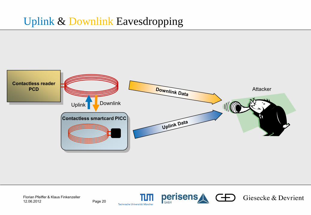
Uplink & Downlink Eavesdropping
Contactless smartcard PICC
Contactless reader
PCD
Downlink Uplink
Attacker
Florian Pfeiffer & Klaus Finkenzeller
12.06.2012 Page 21
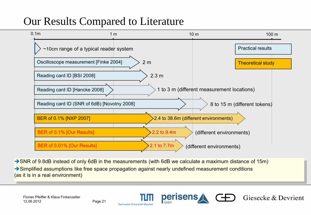
Our Results Compared to Literature 0.1m 1 m
Oscilloscope measurement [Finke 2004]
Reading card ID [BSI 2008]
10 m 100 m
2 m
2.3 m
1 to 3 m (different measurement locations)
8 to 15 m (different tokens)
~10cm range of a typical reader system
2.4 to 38.6m (different environments) BER of 0.1% [NXP 2007]
Reading card ID (SNR of 6dB) [Novotny 2008]
Reading card ID [Hancke 2008]
Practical results
Theoretical study
2.2 to 9.4m BER of 0.1% [Our Results]
SNR of 9.8dB instead of only 6dB in the measurements (with 6dB we calculate a maximum distance of 15m)
Simplified assumptions like free space propagation against nearly undefined measurement conditions
(as it is in a real environment)
2.1 to 7.7m BER of 0.01% [Our Results]
(different environments)
(different environments)
Florian Pfeiffer & Klaus Finkenzeller
12.06.2012 Page 22
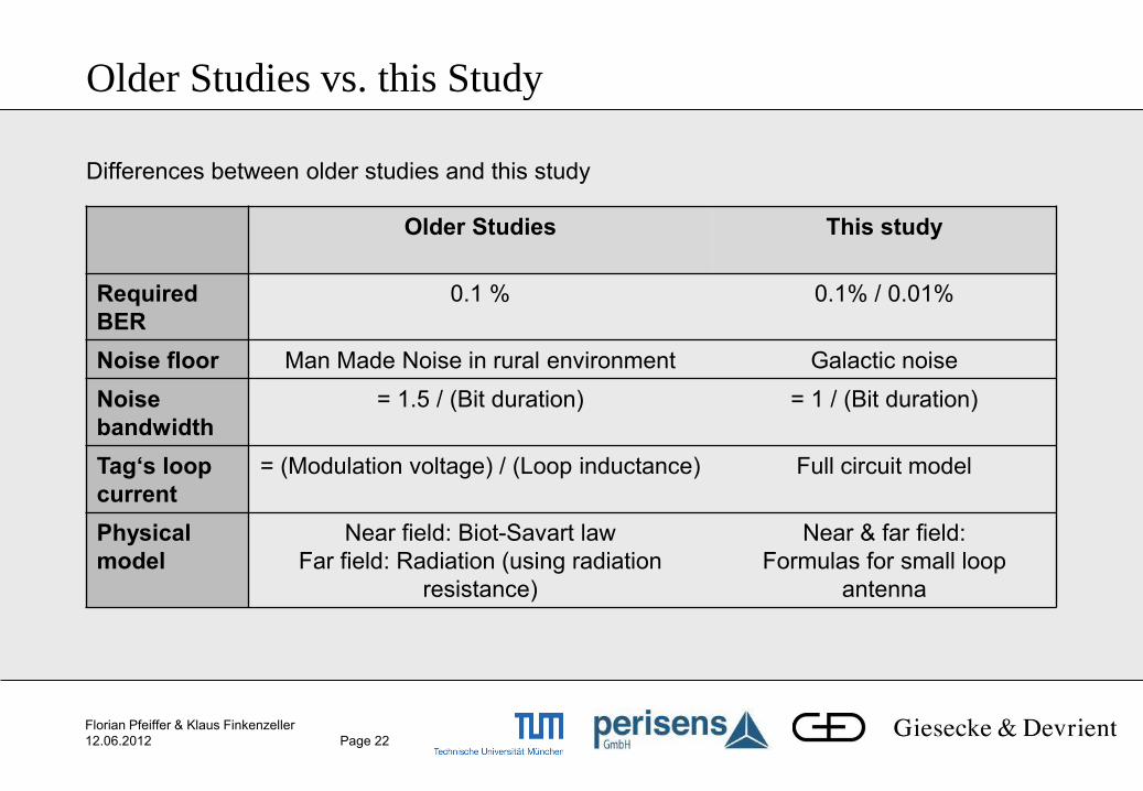
Older Studies vs. this Study
Older Studies
This study
Required
BER
0.1 % 0.1% / 0.01%
Noise floor Man Made Noise in rural environment Galactic noise
Noise
bandwidth
= 1.5 / (Bit duration) = 1 / (Bit duration)
Tag‘s loop
current
= (Modulation voltage) / (Loop inductance) Full circuit model
Physical
model
Near field: Biot-Savart law
Far field: Radiation (using radiation
resistance)
Near & far field:
Formulas for small loop
antenna
Differences between older studies and this study

Florian Pfeiffer & Klaus Finkenzeller
12.06.2012 Page 23
Conclusion
Bottleneck of the eavesdropping range is the detection of the uplink signal
A higher magnetic field of the reader reduces the detection range of the uplink signal due to the control behaviour of the IC chip
Theoretic range lies between 2.2 and 9.4m (for BER of 0.1%) and 2.1 and 7.7m (for BER of 0.01%) – both with coherent modulation
Calculation are performed under simplified assumptions as free space propagation & pure Gaussian noise
range limits can only give an indication for measurements (coupling into pipes/wires could also cause excessive range)


![Rf Mgr Mnmn 14443 Refguide[1]](https://img.pdfslide.us/doc/110x75/577cd51a1a28ab9e7899e3c2/rf-mgr-mnmn-14443-refguide1.jpg)