Embed Size (px)
Citation preview

Al-Rafidain Engineering Journal (AREJ) ISSN (Print) 1813-0526;
Vol.24, No1, October 2019, pp. 10-18 ISSN (Online) 2220-1720
Al-Rafidain Engineering Journal (AREJ) Vol.24, No1, October 2019, pp. 10-18
Theoretical Stress Analysis of Gas Turbine Blade Made From
Different Alloys
*Suha Hashim Ahmed **Ghaidaa Ibrahim Husain ***Majeed Ali Abdulrazaq Assistant Lecturer Assistant Lecturer Assistant Lecturer
[email protected] [email protected] [email protected]
*, ** Department of Mechanical Engineering, University of Mosul
*** Department of Mechanical Engineering, University of Zakhoo
Received: 19-11-2018 Accepted: 30-4-2019
ABSTRACT Blades may be considered to be the heart of turbine without blade there would be no power and the slightest
fault in blade would mean a reduction in efficiency and costly repairs.
The centrifugal force is one of the problems faced by the designer of blades especially at the first stages. The designer
aims at reducing the stresses with in the allowed limit.
The ANSYS 15 software was used as far as it is the most effective in analyzing the different numerous cases of stresses,
the blades with limited root in all direction (X,Y,Z) were taken into consideration . The centrifugal forces were applied on
the rotor blades at running speed of 6000 r.p.m., The finite element models of the blade were constructed using D3-10-
noded Tetrahedron elements shape, SOLID 187, mesh of the entire blade 23406 Node,136575element. The average of
normal stress, Von misses, Maximum principle stress, Minimum principle stress were calculated according to ANSYS 15
program, these stresses are as the result of the effect of centrifugal force for all planes along the blades and then values
of stresses were compared to the curves for each alloy.The current research concluded that the Titanium alloy is the best
alloy used in terms of reducing stresses due to centrifugal force, that is because density of Titanium alloy used is less
than that of other used alloys, leading a reduction in centrifugal forcess that are directly proportional to mass.
Keywords:
Gas turbine blade; inconel 625, inconel 718 MarM-200; Titanium alloys; Centrifugal stress; ANSYS15;
Stress analysis.
Copyright © 201x College of Engineering, University of Mosul, Mosul, Iraq. All rights reserved.
https://rengj.mosuljournals.com
Email: [email protected]
=============================================================================
1. INTRODUCTION
Shattering of turbine blades are one of
the most critical troubles in power generating
industry. Rotor blades are the very generally used
machine parts used in high-technics applications
and in general are used as a lot of arrangement
mechanical element. These blades are subjected
to different loads like centrifugal loading.
Centrifugal forces is the main component
participate in to the stress produced in the blades
[1].
Centrifugal loads are formed by high
rotational speeds at (6000 r.p.m).The formed
Centrifugal force depend upon the size of the
rotor and the rotational speed of the rotor. As it is
well known, that the centrifugal force Fc can be
defined as :
Fc = mrw², where, (m) is the mass (kg),
(r) is the radius of rotation and w² is the angular
speed. Gas turbine blades alloys are designed
mainly to protect the structural material against
loads, corrosion, oxidation, erosion and high
temperature environments.
The main reason of shut down in turbo
machine is the shatter of rotor blade. The failure
of the rotor blade may guide to serious
consequences both physically and economically.
Hence, the suitable design of the turbo machine
blade plays a necessary role in the suitable
functioning of the turbo machine [5].

Suha Hashim Ahmed: Theoretical Stress Analysis of Gas Turbine ….. 11
Al-Rafidain Engineering Journal (AREJ) Vol.24, No1, October 2019, pp. 10-18
In the current study, the first stage rotor
blade of a two-stage gas turbine has been
analyzed for structural static using ANSYS
15.0Software which is powerful Finite Element
Software. In the process of getting mechanical
stresses in the rotor blade has been evaluated
using four different alloys; namely: Inconel 718,
Inconel 625, MarM200,
Titanium alloys .And the dimensions of
the blade for the current study shown in
Table.1.The blade was cut into twenty one
sections along the length of the Airfoil with
ANSYS software as shown in Fig.1The finite
element models of the blade were constructed
using D3-10-noded Tetrahedron elements shape,
SOLID 187, mesh of the entire blade 23406
Node, 136575 element as shown in Fig. 2. And all
results take from the option of the average of
stresses in ANSYS software as shown in Fig.3.
Table 1: Dimensions of the blade Total length
of blade Length of
root Length of
Airfoil Length of
hollow
157mm 62mm 95mm 52.1mm
Fig. 1 Shown the sections along the length of blade
used in the analysis
Fig. 2 Shows the generated finite element Mesh
used in the current investigation
Fig. 3 Showsthe place of Max.principle stress in
tenth section.
2. LITERATURE RIVEW
Theju et.al[8]had mainly done the research work
on jet engines turbine blade; the study was done
on two different materials Inconel718 and
Titanium T-6 alloy to discuss the effect of
temperature and induced stresses on turbine
blade. The study complemented that the Titanium
T-6 would have minimum value of deformation
and lesser strength.
Naga Bhushana Rao et.al[9] had done
research on turbine blade used in marine
applications. The blade was observed for
structural analysis at elevated temperatures and
under the action of large centrifugal
force, the material used was nickel based
super alloy, it was investigated that high
stresses and strains were observed near to
the root of the turbine blade and upper
surface along the blade root, maximum
temperature is observed at the blade tip
and minimum at the root of the blade.
3. MATERIAL AND MATERIAL
PROPERTIES
Four alloys have been used in the current study:
3-1- INCONEL 718&INCONEL 625 alloys
It is a high strength, heat resistant
superalloy (HRSA) that is used extensively by the
aerospace industry for the hot parts of gas turbine
engines such as, turbine disks, blade .[2]
3-2-Mar M-200 alloy
The material of the blade is taken as
MAR M-200 isconsider superNickel alloy. It is
one of the proper material for blades of Gas
turbineon account of its altitude yield strength,

12 Suha Hashim Ahmed: Theoretical Stress Analysis of Gas Turbine …..
Al-Rafidain Engineering Journal (AREJ) Vol.24, No1, October 2019, pp. 10-18
endurance limit and its ability to stop therising of
temperatures [1].
3-3-Titanium Alloy
Accelerates formation of chromia at
metal/oxide interface; decrease thermal expansion
coefficient in Ni base alloys. These titanium
alloys are foundamentlly used for represent
materials for hard tissues.[3].
Table2: Mechanical properties of Inconel 625,
MarM-200 & Titanium alloy [6,4,1,3].
4. RESULTS AND DISCUSSIONS
Following Fig.(4,to7) show the results of
stress analysis in INCONEL625 alloy,we notice
that the concentration of stresses rate is in the
back of the base of the airfoil,which gradually
decreases along the airfoil near the top of the
blade, because the centirfugal force is higher at
the base and lower at the top of the blade due to
the decrease in the mass of blade whenever the
direction from the base to the top of the blade and
Table(3) show the average stresses on
INCONEL625.
Fig. 4 Shows themaximum principle stress for
INCONEL625 alloy.
Fig. 5 Shows the minimum principle stress for the
INCONEL625 alloy blade.
Fig. 6 Shows thenormal stress for the
INCONEL625 alloy blade.
Fig. 7 Shows the Von misses stress for the
INCONEL625 alloy blade.
Property Inconel6
25 alloy [6]
Inconel718
alloy[4]
MarM200 alloy[1]
Titanium alloy[3]
Density (kg / m³)
8400 8190 8526 4540
Poisson´s ratio
0.3 0.22 0.33 0.33
Modulus of
Elasticity (Gpa)
145 200 220 206.84

Suha Hashim Ahmed: Theoretical Stress Analysis of Gas Turbine ….. 13
Al-Rafidain Engineering Journal (AREJ) Vol.24, No1, October 2019, pp. 10-18
Table 3: Results of averge stress analysis of blade
of gas turbine made from INCONEL625 alloy by
ANSYS program at all sections along the blade.
The following Fig. (8 to 11) show the
stress analysis for INCONEL718 alloy,the result
obtaained can be discussed as an ANSYS
program where the value of the largest stress at
the base of the airfoil and the lowest at the top of
the blade is explained by the fact the high
centrifugal force at the base of the airfoil and less
as we movement to the top of the blade, and
Table(4) show the average stresses on INCONEL
718.
Fig. 8 Shows the maximum principle stress for
the INCONEL718 alloy.
Fig. 9 Shows theminimum principle stress for
INCONEL718 alloy.
Fig. 10 Shows thenormal stress for
INCONEL718 alloy.
Fig. 11 Shows the Von misses stress for the
INCONEL718 alloy.
Section No.
Normal stress (MPa)
Von misses (MPa)
Maximum principle
stress (MPa)
Minimum
principle stress (MPa)
1 11942 10300 12510 2520
2 11700 10240 12030 1022
3 11034 10250 11110 239
4 10362 9950 10410 40
5 9662 9454 9714 12
6 8940 8865 9005 11
7 8197 8201 8276 -1
8 7428 7452 7521 -108
9 6666 6939 6853 -422
10 6198 8243 6321 -2367
11 9423 9399 9480 -124
12 8517 8592 8579 -148
13 7602 7727 7666 -121
14 6678 6831 6744 -296
15 5748 5917 5811 -349
16 4800 4997 4866 -395
17 3846 4079 3914 -439
18 3000 3174 2954 -488
19 1908 2305 1999 -541
20 1300 1539 1115 -600
21 0.5 1302 100 -788

14 Suha Hashim Ahmed: Theoretical Stress Analysis of Gas Turbine …..
Al-Rafidain Engineering Journal (AREJ) Vol.24, No1, October 2019, pp. 10-18
Table 4: Result of average stress analysis on blade
of gas turbine made from INCONEL718 alloy by
ANSYS programat all sections along the blade.
The following Fig. (12- to 15) show the
resultof MarM-200 alloy blade,the highest value
of the stresses is at the base of the airfoil,the
reason is that the centrifugal force are high at the
base of airfoil and decrease as we move up at the
top of the blade this is due to the gradual
reduction of the blade mass along the airfoil, and
Table(5) show the average stresses on MarM-200.
Fig. 12 Shows themaximum principle stress for
Mar-M200 alloy.
Fig. 13 Shows the minimum principle stress Mar
M-200 alloy.
Fig. 14 Show the normal stress for Mar M-200
alloy.
Fig. 15 Show theVon misses stress for Mar M-
200.
Section No.
Normal stress (MPa)
Von misses (MPa)
Maximum principle
stress (MPa)
Minimum principle
stress (MPa)
1 12263 10278 11700 1664
2 11423 10247 11680 896
3 10750 10125 10820 234
4 10103 9763 10150 38
5 9421 9240 9474 7
6 8716 8640 8782 5
7 7993 7983 8071 4
8 7241 7245 7335 -70
9 6498 6716 6680 -331
10 6060 8007 6192 -2263
11 9187 9238 7245 -190
12 8304 8400 4557 -168
13 7412 7535 4525 -215
14 6511 6655 4515 -280
15 5600 5765 3684 -330
16 4681 4868 2773 -373
17 3709 3970 1865 -440
18 2811 2799 1127 -460
19 1860 2237 1121 -511
20 899 1488 1090 -572
21 0.7 1234 559 -748
Suha Hashim Ahmed: Theoretical Stress Analysis of Gas Turbine ….. 15
Al-Rafidain Engineering Journal (AREJ) Vol.24, No1, October 2019, pp. 10-18
Table 5: Result of average stress analysis on blade
of gas turbine made from Mar M-200 alloy by
ANSYS programat all sections along the blade.
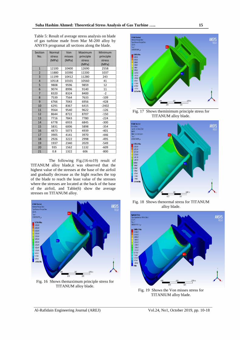
The following Fig.(16-to19) result of
TITANUM alloy blade,it was observed that the
highest value of the stresses at the base of the airfoil
and gradually decrease as the hight reaches the top
of the blade to reach the least value of the stresses
where the stresses are located at the back of the base
of the airfoil, and Table(6) show the average
stresses on TITANUM alloy.
Fig. 16 Shows themaximum principle stress for
TITANUM alloy blade.
Fig. 17 Shows theminimum principle stress for
TITANUM alloy blade.
Fig. 18 Shows thenormal stress for TITANUM
alloy blade.
Fig. 19 Shows the Von misses stress for
TITANIUM alloy blade.
Section No.
Normal stress (MPa)
Von misses (MPa)
Maximum principle
stress (MPa)
Minimum principle
stress (MPa)
1 12100 10400 12690 2558
2 11880 10390 12200 1037
3 11199 10412 11280 243
4 10518 10101 10560 41
5 9808 9596 9859 12
6 9074 8996 9140 11
7 8320 8324 8400 -2
8 7539 7564 7633 -109
9 6766 7043 6956 -428
10 6291 8367 6415 -2402
11 9564 9540 9622 -126
12 8644 8722 8707 -150
13 7716 7843 7780 -224
14 6778 6933 6845 -300
15 5831 6006 5898 -354
16 4873 5073 4939 -401
17 3905 4141 3970 -446
18 2926 3222 2998 -495
19 1937 2340 2029 -549
20 935 1562 1132 -609
21 0.8 1322 606 -800

16 Suha Hashim Ahmed: Theoretical Stress Analysis of Gas Turbine …..
Al-Rafidain Engineering Journal (AREJ) Vol.24, No1, October 2019, pp. 10-18
Table 6: Result of average stress analysis on blade
of gas turbine made of TITANIUM alloy by
ANSYS program in all sections along the blade.
The following Fig.(21,22,23,24)
comparison for all alloys used in current
research.The concentration of the stresses is at the
base of the airfoil for all the alloys used in this
study.and the resulting stresses, such as normal
stress,maximum&minimum principle stress and
von misses stresswhich were analyzed by the
ANSYS software are lower in Titanium alloy than
other alloys because the density of Titannium is
less than the density of other alloys.
Fig. 21 Shows thecomparison of normal stresses
for four different alloys used in this study.
Fig. 22 Shows comparisonof Maximum principle
stresses for four different alloys used in this
study.
Fig. 23 Shows comparison of Minimum principle
stresses for four different alloys used in this
study.
Fig. 24 Showscomparison of Von misses
stresses for four different alloys used in this
study.
0
2000
4000
6000
8000
10000
12000
14000
1 3 5 7 9 11 13 15 17 19 21
Inconel 625
Inconel 718
MarM 200
Titanium
number of section
No
rmal
str
ess
(M
Pa)
0
2000
4000
6000
8000
10000
12000
14000
1 3 5 7 9 11 13 15 17 19 21
Inconel625
Inconel718
MarM200
Titanuim
Max
.pri
nci
ple
str
ess
(MP
a)
Number of section
-3000
-2000
-1000
0
1000
2000
3000
1 3 5 7 9 11 13 15 17 19 21
Inconel 625
Inconel 718
MarM200
Titanium
number of section
min
.pri
nci
ple
str
ess(
MP
a)
0
2000
4000
6000
8000
10000
12000
1 3 5 7 9 11 13 15 17 19 21
Inconel625
Inconel718
MarM200
TITANIUM
Vo
n m
isse
s (
MP
a)
Number of section
Section No.
Normal stress (MPa)
Von misss stress (MPa)
Maximum principle
stress (MPa)
Minimum principle
stress (MPa)
1 6637 5540 6760 1362
2 6031 5535 6504 552
3 5963 5530 6004 130
4 5601 5379 5625 22
5 5223 5110 5250 7
6 4832 4791 4867 6
7 4430 4433 4473 0
8 4014 4027 4064 -58
9 3603 3750 3704 -228
10 3350 4455 3416 -1279
11 5097 5080 5123 -67
12 4603 4644 4636 -79
13 4109 4176 4140 -119
14 3609 3691 3644 -160
15 3105 3198 3140 -186
16 2595 2701 2630 -214
17 2079 2205 2115 -238
18 1559 1715 1597 -264
19 1031 1245 1080 -292
20 498 831 602 -324
21 0.4 704 322 -426

Suha Hashim Ahmed: Theoretical Stress Analysis of Gas Turbine ….. 17
Al-Rafidain Engineering Journal (AREJ) Vol.24, No1, October 2019, pp. 10-18
5. CONCLUSION
The results achieveddue to the
centrifugal forces on the blade is debated below.
1-It was conclusion that the stresses produced by
the centrifugal forces (normal stress, maximum
and minimum principle stress, von misses
stress) were concentrated at the base airfoil
from the back.
2-It was observed that stresses along the blade be
higher value when back to the root and less at
the top of the blade as shown in
Fig.(21,22,23,24).
3-The centrifugal force depends on the mass
where all less than the mass of the blade less
centrifugal force and thus reduce the stresses
resulting from this force , which was observed
in the Titanium alloy of less density compared
with the other alloys .
4-The tensile strength(normal stress) of the
centrifugal force on the blade made of the
Titanium alloy density is less than the tensile
stress caused by the other alloys because the
Titanium alloy density is lower than that of the
other alloys thiscauses to reduce centrifugal
force then causes to reduce stresses as shown
in Fig.(21).
5-Maximum principle stress of the blade made of
Titanium alloy has less than the maximum
principle stress of the blade made of alloy s
Inconel625,Inconel718,MarM-200) because the
Titanium alloy density is lower than that of the
other alloys so causes to reduce centrifugal
force then causes to reduce stresses as shown
in Fig.(22) & Fig.(4,8,12,16).
6-That the negative value of the minimum
principle stress of all alloys used indicate that
the blade is subjected to compression stress in
some blade parts of all alloys used as shown in
Fig.(23) .
7-It was noted that the highest stress equivalent to
the blade made of Titanium alloy is 26089Mpa,
and the equivalent stress of the blade made of
Inconel625 is 48271Mpa, and the highest
equivalent stress of blade made of Inconel718 is
47631Mpa, and the equivalent stress on the
blade made of Mar M200 is 48995MPa this
shows that the best on the safe matter of the high
stresses is the titanium alloy this is due to the
fact that Titanuim alloy density is less than the
density of the alloys used as shown in
Fig.(6,11,15,20) .
8-It is conculosion thatthe Titanium alloy is the
best alloy used in terms leading to reduce
stresses due to centrifugal force, because
density of Titanium alloy used is less than of
other used alloys,so,leading a reduction in
centrifugal forcess which are directly
propotional to mass,there by reducing the
stresses of these forces to the Titanium alloy
that is density less than of the alloys used in
this study.
9-It was noted that the results of stresses for the
INCONEL718,INCONEL625 and MarM-200
alloys are closer, they are nicle base alloys and
they have the nearestdensity
REFERENCES [1] Ajit Prasad, K.Ramachandra, M.Pradeepand
K.Kumar"Effect Of Rubbing Forces Due To
Centrifugal Loading On Rotor Blades"(2004).
[2] SK Bhatti S Chandra Prasad D Radha Krishna
IN Niranjan Kumar BVARao"LIFE
EVALUATION METHOD FOR GAS
TURBINE BLADES MADE OF INCONEL718
ALLOY" Proceedings of the 2nd WSEAS Int.
Conference on Applied and Theoretical
Mechanics, Venice, Italy,208, November( 20-
22, 2006).
[3] Mats Eskner "Mechanical Behavior of Gas
Turbine Coatings" Royal Institute of
Technology,Stockholm (2004).
[4] R.A. CLÁUDIO, C.M. BRANCO, E.C.
GOMES, J. BYRNE" LIFE PREDICTION OF
A GAS TURBINE DISC USING THE FINITE
ELEMENT METHOD" 8AS JORNADAS DE
FRACTURA,(2002).
[5] AHMED ABDULHUSSEIN JABBAR1, A. K.
RAI2, P. RAVINDER REEDY" DESIGN AND
ANALYSIS OF GAS TURBINE ROTOR
BLADE USINGFINITE ELEMENT
METHOD"International Journal of Mechanical
and Production,ISSN(P): 2249-6890; ISSN(E):
2249-8001, Vol. 4,73-94, Issue 1, Feb (2014).
[6] P.V.Krishnakanth1, G.Narasa Raju2, R D V.
Prasad3, R. Saisrinu4 ," Structural & Thermal
Analysis of Gas Turbine Blade by Using
F.E.M" International Journal of Scientific
Research Engineering & Technology (IJSRET),
Volume 2 Issue2 pp 060-065, ISSN 2278 –
0882,May (2013).
[7] Help of ANSYS program V (15.0),(2016).
[8] Theju V,Uday PS,PLV Gopinath Reddy,C.J.
Manjunath, ―Design and Analysis of Gas
Turbine Blade, International Journal of
Innovative Research in Science, Engineering
and Technology, ISSN: 2319-8753,June,(2014).
[9] V.NagaBushanaRao,N.Niranjan
Kumar,N.Madhulata,A.Abhijeet,Mechanical
Analysis Of 1st Stage Marine Gas Turbine
Blade‖,International Journal Of
AdvancedScience and andTechnology,pp.57-
64, vol.68,(2014).

18 Suha Hashim Ahmed: Theoretical Stress Analysis of Gas Turbine …..
Al-Rafidain Engineering Journal (AREJ) Vol.24, No1, October 2019, pp. 10-18
مختلفة سبائكالغازي المصنوع من اترش التوربن الجهاد النظري التحلل
مجذ عل عبذ الرزاق*** حسنغذاء ابراهم **أحمذ هاشم سهى* مذرس مساعذ مذرس مساعذمذرس مساعذ
المكانك، كلةالهنذسة، جامعة الموصل الهنذسة القسم ** ,*
زاخوجامعة المكانك، كلةالهنذسة، الهنذسة القسم ***
:الخالصة
اسخخذيج انعاصش , حعخبش انشش قهب انخسب بذ انشش ال حخذ طاقت إ ا خهم فا ؤد ان اخفاض انكفاءة بخصهحاث يكهفت
باسخخذاو خى ححهم اإلخاداث انكاكت .نهحصل عه حهل حقشبت ندعت اسعت ي انشاكم انذست( ANSYS15)انحذدة ببشايح إر حى اعخباس انششت يقذة اندزس ف خع اإلحدااث , انعاصش انحذدة نألغشاض انعايت بصف أداة فعانت ف ححهم اإلخاداث انخخهفت
(Z,Y,X ) اضافت خع انخاص انكاكت نهشش باسخخذاو بشايح(ANSYS15 ) حى حقطع انششت ان اسحفاعاث يخسات عه طلحى باء ارج انعاصش انحذدة , (دققت/ دسة 6000) ق انطشد انشكض يسهطت عه انشش احدت ي دسا انذاس بسشعت , شتانش
136575,ششحت 23406سدت انعاصش انحذدة نكايم انششت انك ي , 187صفحت , عقذة ي ع سباع انسطذ 3D-10باسخخذاو ز , (ANSYS15)اإلخاد انشئس األعه اإلخاد انشئس األد ببشايح , اإلخاد انكافء, عذل اإلخاد انعد حى اسخخشاج ي, عقذة
حسخخح انذساست انحانت ان إ سبكت انخخاو , اإلخاداث احدت ي حأثش ق انطشد انشكض ز انقى قسج بحاث نكم سبكتث حقهم اإلخاداث اناحدت ع ق انطشد انشكض يقاست بانسبائك األخش انسخخذيت رنك ال كثافت سبكت انخخاو افضم سبكت ي ح
ز اقم ي كثافت انسبائك االخش انسخخذيت حث إ قة انطشد انشكض حخاسب طشدا يع انكخهت يا ؤد ان حقهم اإلخاداث اناحدت ع .انخخاو األقم كثافت ي ب انسبائك انسخخذيت ف ز انذساستانق نسبكت
ححههم اإلخاداث,سبائك يخخهفت,سش انخسب انغاص :الكلمات الذالة