Embed Size (px)
Citation preview
U.P.B. Sci. Bull., Series D, Vol. 78, Iss. 2, 2016 ISSN 1454-2358
THEORETICAL RESEARCHES ON KINEMATICS OF CAM - ROCKER MECHANISMS FROM SEED DRILLS
TRANSMISSION
Dragoş MANEA1, Gheorghe VOICU2, Gigel PARASCHIV3, Eugen MARIN4
Design of seed drills transmissions, which are composed of cam-rocker mechanisms, starts from their functional role, namely providing a range of transmission ratios to fully cover the range needed to make seeding norms of any type of agricultural crop. The transmission ratio is dependent on the size of the input (rotation angle of the camshaft) and the amplitude of oscillation of the rocker. The mathematical model developed in this paper allows obtaining the theoretical transmission ratios of the mechanism at which the contact between the leading element (cam) and the follower (rocker) is directly made and the roller of rocker moves on a plate for limiting the stroke.
Keywords: mechanism, kinematics, transmission ratio
1. Introduction
To ensure the correspondence of the forward speed of the seed drill and the amount of seeds to be distributed per unit area, in practice there are two main types of transmissions, namely: a) gear drive (Northon gearboxes), that deliver 24 ... 128 transmission ratios, for each transmission ratio value being achieved a certain seeding norm [1,2]. Disadvantages of using the Northon type gear mechanism in the transmission system are: large constructive dimension; high weight; complicated adjustments; require lubrication after few hours of operation; they have components subject to erosion. b) transmissions with cam - rocker mechanisms, which provide the driving of devices for seeds distribution, through an intermittent motion (the case presented in this paper).
1 Lect., Dept.of Biotechnical Systems, University POLITEHNICA of Bucharest, Romania, e-mail: [email protected] 2 Prof., Dept.of Biotechnical Systems, University POLITEHNICA of Bucharest, Romania, e-mail: [email protected] 3 Prof., Dept.of Biotechnical Systems, University POLITEHNICA of Bucharest, Romania, e-mail: [email protected] 4 Scientific Researcher, National Institute of Research-Development for Machines and Installations Designed to Agriculture and Food Industry - INMA Bucharest, e-mail: [email protected]
200 Dragoş Manea, Gheorghe Voicu, Gigel Paraschiv, Eugen Marin
Worldwide, renowned manufacturers of agricultural machinery (ex. Pottinger, Gaspardo) used cam mechanisms in transmission of seed drills, due to the multiple benefits they offer, namely: simplified construction and operations of distribution control, reduced manufacturing costs and improved machine design. Also, it ensures the very precise distribution of seeds and the possibility of easy adjustment of the amount of seed per hectare. In Romania, investigations undertaken until year 1999, to promote transmission with cam mechanism on the seed drills, were nonexistent. Since 1999, National Institute of Research-Development for Machines and Installations Designed to Agriculture and Food Industry - INMA Bucharest was researched and introduced into series manufacturing a mechanism having two cams mounted parallel and out of phase, that can adapt on all machines for sowing cereals in operation [3]. In the paper [4], the author has studied the kinematics of a cam mechanism, cam having four lobes and the contact between the leading element (cam) and follower (rocker) is done via a roller and the return stroke of the rocker is limited by a limiting plate. Using computer-aided simulation with ProEngineer software design, author of paper [5] performed virtual prototyping and studied kinematic of a cam - rocker mechanism, cams having several lobes.
Cam mechanisms are composed of an upper kinematic coupling, carried out by contact of a leading element, having a certain profile, called cam and a follower called rocker, moving according to a law determined by the shape of the cam profile. Maintain permanent contact between the cam and the rocker is achieved through a resilient force generated by coil springs. For kinematic analysis of the cam mechanisms may be used graphical, grapho - analytical or analytical methods. The graphic method or analytical charts method can be applied directly or by reversing motion of mechanism elements. This method consists of tracking of cam successive positions, during a complete rotation, which is difficult, leading to complex figures, difficult to analyze [6, 7]. With graphical method, derivation and graphical integration of kinematic diagrams introduces method errors, which are much higher as these operations are repeated. Another method for the analysis of the kinematics of the cam mechanism is a mechanisms replacement method, which consists in replacing the upper kinematic coupling of the cam mechanism through a chain of lower couplings to obtain in the end a mechanism equivalent in terms of kinematics with that is analyzed [7]. Graphic - analytical analysis methods, based on mathematical algorithms more or less sophisticated and processing the results as graphs, are commonly used today, they ensure maximum precision of the results. Analysis can be performed with specialized programs made on the platform programming
Theoretical research on kinematics of cam - balance mechanisms from drills transmission 201
language (ex. Basic, Pascal, C ++), with programs aided design (ex. SolidWorks, Catia, ProEngineer) or performance software based on the theory of mechanical multi-body systems (ex. Adams, Plexus). In the present paper, we used the classical approach, using the programming language Turbo Pascal, the theoretical model of the mechanical system is described by analytic relations which materialize functions of motion, we transposed the mathematical relations into programming language code and set numerical algorithm for solving.
2. Object of kinematic analysis
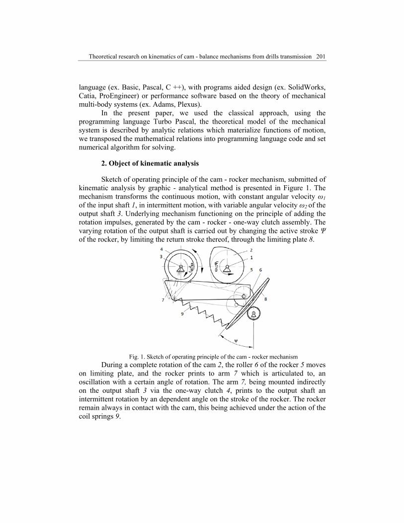
Sketch of operating principle of the cam - rocker mechanism, submitted of kinematic analysis by graphic - analytical method is presented in Figure 1. The mechanism transforms the continuous motion, with constant angular velocity ω1 of the input shaft 1, in intermittent motion, with variable angular velocity ω2 of the output shaft 3. Underlying mechanism functioning on the principle of adding the rotation impulses, generated by the cam - rocker - one-way clutch assembly. The varying rotation of the output shaft is carried out by changing the active stroke Ψ of the rocker, by limiting the return stroke thereof, through the limiting plate 8.
Fig. 1. Sketch of operating principle of the cam - rocker mechanism
During a complete rotation of the cam 2, the roller 6 of the rocker 5 moves on limiting plate, and the rocker prints to arm 7 which is articulated to, an oscillation with a certain angle of rotation. The arm 7, being mounted indirectly on the output shaft 3 via the one-way clutch 4, prints to the output shaft an intermittent rotation by an dependent angle on the stroke of the rocker. The rocker remain always in contact with the cam, this being achieved under the action of the coil springs 9.
202 Dragoş Manea, Gheorghe Voicu, Gigel Paraschiv, Eugen Marin
3. Mathematical modelling of the cam - rocker mechanism
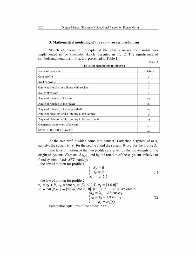
Sketch of operating principle of the cam - rocker mechanism was implemented in the kinematic sketch presented in Fig. 2. The significance of symbols and notations in Fig. 2 is presented in Table 1.
Table 1 The list of parameters in Figure 2
Name of parameter Notation
Cam profile 1
Rocker profile 2
One-way clutch arm solidary with rocker 3
Roller of rocker 4
Angle of rotation of the cam φ1
Angle of rotation of the rocker φ2
Angle of rotation of the output shaft φ3 Angle of plate for stroke limiting to the vertical ψ Angle of plate for stroke limiting to the horizontal Ө Geometric parameters of the cam a, r Stroke of the roller of rocker S4
At the two profile which come into contact is attached a system of axis, namely: the system 11yFx for the profile 1 and the system 22 yBx for the profile 2. The laws of motion of the two profiles are given by the movements of the origin of systems 11yFx and 22 yBx , and by the rotation of these systems relative to fixed system of axis XFY, namely: - the law of motion for profile 1:
00 (1)
- the law of motion for profile 2: , where 0 , 1 0 0
, |sin cos 0|, (i=1, 2, 3); |0 0 1|, we obtain: cossin (2)
Parametric equations of the profile 1 are:
Theoretical research on kinematics of cam - balance mechanisms from drills transmission 203
(3)
cos
sin (4)
where λ is the curve generation parameter.
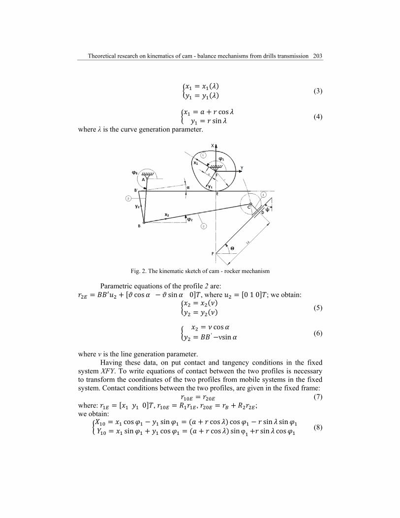
Fig. 2. The kinematic sketch of cam - rocker mechanism
Parametric equations of the profile 2 are:
cos sin 0 , where 0 1 0 ; we obtain:
(5)
cos′ νsin (6)
where ν is the line generation parameter. Having these data, on put contact and tangency conditions in the fixed system XFY. To write equations of contact between the two profiles is necessary to transform the coordinates of the two profiles from mobile systems in the fixed system. Contact conditions between the two profiles, are given in the fixed frame:
(7) where: 0 , , ; we obtain:
cos sin cos cos sin sinsin cos cos sinφ sin cos (8)
204 Dragoş Manea, Gheorghe Voicu, Gigel Paraschiv, Eugen Marin
cos cossin sin (9)
cos sin
cos cos cos ′ sin sincos ′ sin cos
sin cossin cos sin ′ sin cos
sin ′ cos sin
(10)
Tangency condition in the fixed system, is given by:
(11)
or:
sin cos 0 (12)
On the profile FABCDPF can be written the vector equation:
(13)
which produces two equations, namely:
cos cos cos 2 cos sin sin sin 2 sin
(14)
or: cos cos sin θ cos sin sin cos sin (15)
On the mechanism assembly, is written the complete system of nonlinear equations, as follows:
Theoretical research on kinematics of cam - balance mechanisms from drills transmission 205
cos cos sin θ cos 0 sin sin cos sin 0
cos cos cos ′ sin cossin sin sin ′ cos sin
sin cos 0
16)
The system (16) can be written as:
, , , , cos cos cos sin 0, , , , sin sin sin cos 0
, , , , cos ′ sin cos cos cos, , , , sin ′ cos sin sin sin
, , , , 32 0
(17) The unknowns of the system (17) are: , , , , . To solve the system we used gradient method, a method described in detail in [8] and [9].
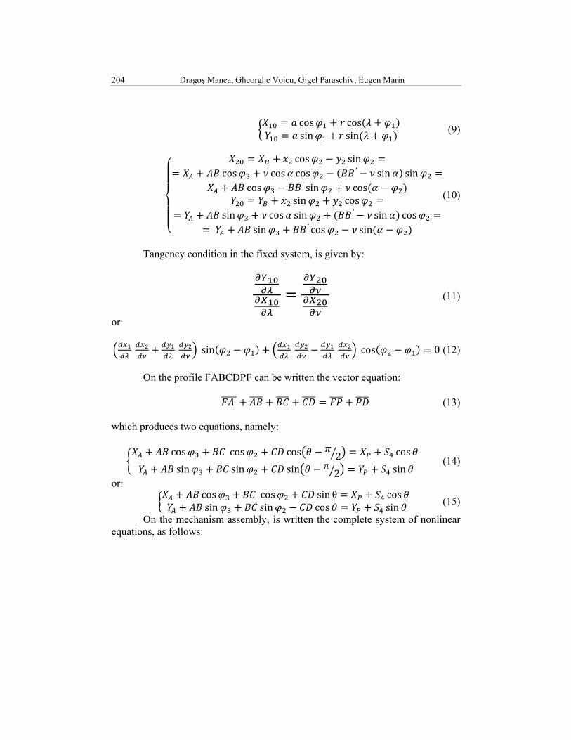
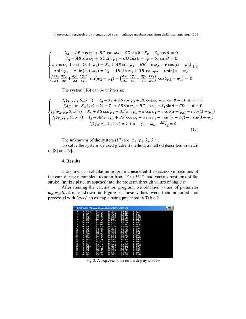
4. Results The drawn up calculation program considered the successive positions of
the cam during a complete rotation from 1° to 361° and various positions of the stroke limiting plate, transposed into the program through values of angle ψ.
After running the calculation program, we obtained values of parameter , , , , as shown in Figure 3, these values were then imported and
processed with Excel, an example being presented in Table 2.
Fig. 3. A sequence in the results display window
206 Dragoş Manea, Gheorghe Voicu, Gigel Paraschiv, Eugen Marin
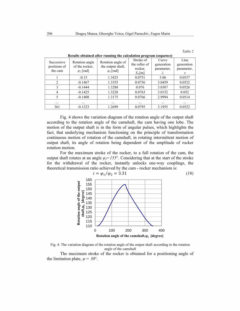
Table 2 Results obtained after running the calculation program (sequence)
Successive positions of
the cam
Rotation angle of the rocker, φ2 [rad]
Rotation angle of the output shaft,
φ3 [rad]
Stroke of the roller of
rocker, S4 [m]
Curve generation parameter,
λ
Line generation parameter,
ν 1 -0.15 1.3423 0.0751 3.06 0.0537 2 -0.1467 1.3355 0.0756 3.0459 0.0532 3 -0.1444 1.3288 0.076 3.0307 0.0526 4 -0.1425 1.3228 0.0763 3.0152 0.052 5 -0.1408 1.3175 0.0766 2.9994 0.0514 ... ... ... ... ... ...
361 -0.1223 1.2699 0.0795 3.1955 0.0522
Fig. 4 shows the variation diagram of the rotation angle of the output shaft according to the rotation angle of the camshaft, the cam having one lobe. The motion of the output shaft is in the form of angular pulses, which highlights the fact, that underlying mechanism functioning on the principle of transformation continuous motion of rotation of the camshaft, in rotating intermittent motion of output shaft, its angle of rotation being dependent of the amplitude of rocker rotation motion.
For the maximum stroke of the rocker, to a full rotation of the cam, the output shaft rotates at an angle φ2=155°. Considering that at the start of the stroke for the withdrawal of the rocker, instantly unlocks one-way couplings, the theoretical transmission ratio achieved by the cam - rocker mechanism is:
3.31⁄ (18)
Fig. 4. The variation diagram of the rotation angle of the output shaft according to the rotation
angle of the camshaft The maximum stroke of the rocker is obtained for a positioning angle of the limitation plate, ψ = 30°.
110115120125130135140145150155160
0 100 200 300 400
Rot
atio
nan
gle
of th
e ou
tput
sh
aft,φ
2 [d
egre
e]
Rotation angle of the camshaft,φ1 [degree]
Theoretical research on kinematics of cam - balance mechanisms from drills transmission 207
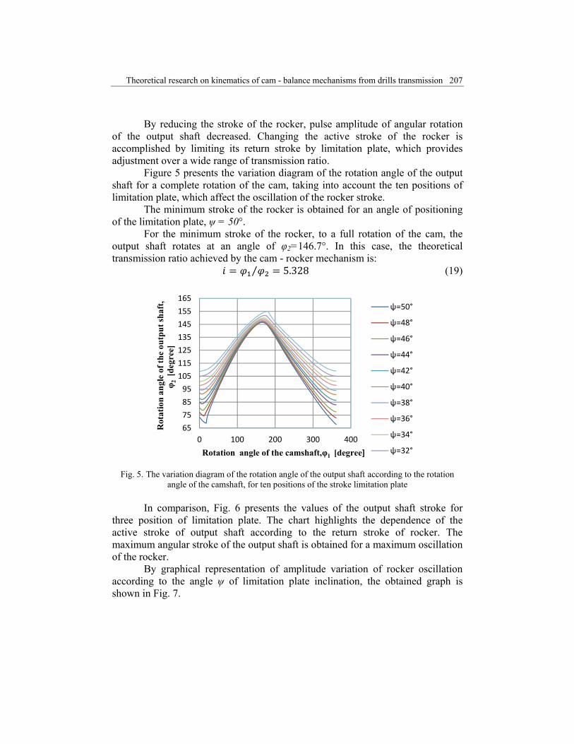
By reducing the stroke of the rocker, pulse amplitude of angular rotation of the output shaft decreased. Changing the active stroke of the rocker is accomplished by limiting its return stroke by limitation plate, which provides adjustment over a wide range of transmission ratio.
Figure 5 presents the variation diagram of the rotation angle of the output shaft for a complete rotation of the cam, taking into account the ten positions of limitation plate, which affect the oscillation of the rocker stroke. The minimum stroke of the rocker is obtained for an angle of positioning of the limitation plate, ψ = 50°.
For the minimum stroke of the rocker, to a full rotation of the cam, the output shaft rotates at an angle of φ2=146.7°. In this case, the theoretical transmission ratio achieved by the cam - rocker mechanism is:
5.328⁄ (19)
Fig. 5. The variation diagram of the rotation angle of the output shaft according to the rotation
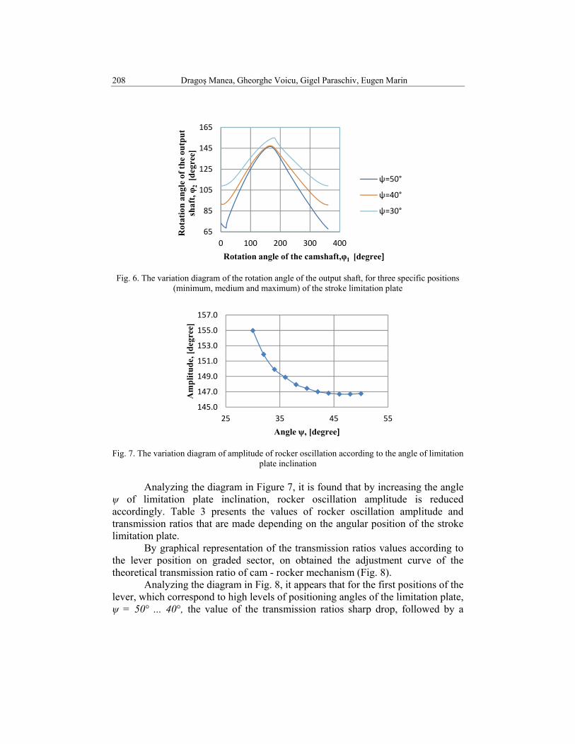
angle of the camshaft, for ten positions of the stroke limitation plate In comparison, Fig. 6 presents the values of the output shaft stroke for three position of limitation plate. The chart highlights the dependence of the active stroke of output shaft according to the return stroke of rocker. The maximum angular stroke of the output shaft is obtained for a maximum oscillation of the rocker.
By graphical representation of amplitude variation of rocker oscillation according to the angle ψ of limitation plate inclination, the obtained graph is shown in Fig. 7.
65
75
85
95
105
115
125
135
145
155
165
0 100 200 300 400
Rot
atio
nan
gle
of th
e ou
tput
shaf
t, φ 2
[de
gree
]
Rotation angle of the camshaft,φ1 [degree]
ψ=50°
ψ=48°
ψ=46°
ψ=44°
ψ=42°
ψ=40°
ψ=38°
ψ=36°
ψ=34°
ψ=32°
208 Dragoş Manea, Gheorghe Voicu, Gigel Paraschiv, Eugen Marin
Fig. 6. The variation diagram of the rotation angle of the output shaft, for three specific positions
(minimum, medium and maximum) of the stroke limitation plate
Fig. 7. The variation diagram of amplitude of rocker oscillation according to the angle of limitation
plate inclination
Analyzing the diagram in Figure 7, it is found that by increasing the angle ψ of limitation plate inclination, rocker oscillation amplitude is reduced accordingly. Table 3 presents the values of rocker oscillation amplitude and transmission ratios that are made depending on the angular position of the stroke limitation plate.
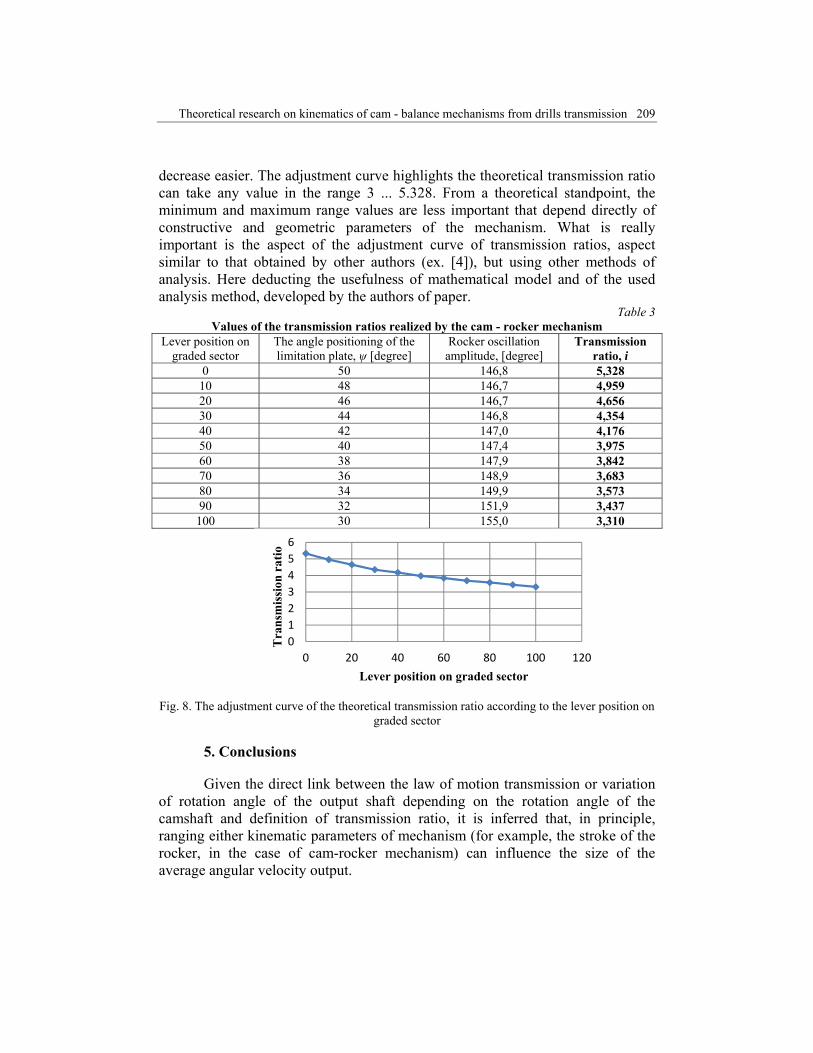
By graphical representation of the transmission ratios values according to the lever position on graded sector, on obtained the adjustment curve of the theoretical transmission ratio of cam - rocker mechanism (Fig. 8).
Analyzing the diagram in Fig. 8, it appears that for the first positions of the lever, which correspond to high levels of positioning angles of the limitation plate, ψ = 50° ... 40°, the value of the transmission ratios sharp drop, followed by a
65
85
105
125
145
165
0 100 200 300 400
Rot
atio
nan
gle
of th
e ou
tput
sh
aft, φ 2
[de
gree
]
Rotation angle of the camshaft,φ1 [degree]
ψ=50°
ψ=40°
ψ=30°
145.0
147.0
149.0
151.0
153.0
155.0
157.0
25 35 45 55
Am
plitu
de, [
degr
ee]
Angle ψ, [degree]
Theoretical research on kinematics of cam - balance mechanisms from drills transmission 209
decrease easier. The adjustment curve highlights the theoretical transmission ratio can take any value in the range 3 ... 5.328. From a theoretical standpoint, the minimum and maximum range values are less important that depend directly of constructive and geometric parameters of the mechanism. What is really important is the aspect of the adjustment curve of transmission ratios, aspect similar to that obtained by other authors (ex. [4]), but using other methods of analysis. Here deducting the usefulness of mathematical model and of the used analysis method, developed by the authors of paper.
Table 3 Values of the transmission ratios realized by the cam - rocker mechanism
Lever position on graded sector
The angle positioning of the limitation plate, ψ [degree]
Rocker oscillation amplitude, [degree]
Transmission ratio, i
0 50 146,8 5,328 10 48 146,7 4,959 20 46 146,7 4,656 30 44 146,8 4,354 40 42 147,0 4,176 50 40 147,4 3,975 60 38 147,9 3,842 70 36 148,9 3,683 80 34 149,9 3,573 90 32 151,9 3,437 100 30 155,0 3,310
Fig. 8. The adjustment curve of the theoretical transmission ratio according to the lever position on
graded sector
5. Conclusions
Given the direct link between the law of motion transmission or variation of rotation angle of the output shaft depending on the rotation angle of the camshaft and definition of transmission ratio, it is inferred that, in principle, ranging either kinematic parameters of mechanism (for example, the stroke of the rocker, in the case of cam-rocker mechanism) can influence the size of the average angular velocity output.
0123456
0 20 40 60 80 100 120
Tra
nsm
issi
on r
atio
Lever position on graded sector
210 Dragoş Manea, Gheorghe Voicu, Gigel Paraschiv, Eugen Marin
As a result, the processes of adjusting the transmission ratio of the cam mechanisms are, in fact, methods of adjusting the angle of oscillation ("pulse") of the follower (rocker). Using graphic - analytical analysis in this paper, in determining the theoretical transmission ratios of cam - rocker mechanisms, represents an original approach, by reference to the theoretical research of the literature studied. The results obtained by the paper's authors allow extending the investigations on the devices made up of two or more cam - balance mechanisms - running parallel. Kinematic analysis of cam - rocker mechanisms, reflected in this paper by graphical representation of the motion laws and determining transmission ratios, depending on the adjustment parameter (stroke of rocker) is a useful aid in both the design kinematics of new solutions construction, and in comparing the performance of existing solutions in order to optimize them.
Acknowledgements
The work has been funded by the Sectoral Operational Programme Human Resources Development 2007-2013 of the Ministry of European Funds through the Financial Agreement POSDRU/159/1.5/S/134398.
R E F E R E N C E S
[1]. C. Scripnic, P. Babiciu, Masini agricole (Agricultural Machines), Ceres Publisher, Bucharest, 1980.
[2]. St. Căproiu, Ma�ini agricole de lucrat solul, semănat şi întreţinerea culturilor (Agricultural Machinery for Soil, Sowing and Crop Maintenance), Didactic and Pedagogic Publishing House, 1982.
[3]. I. Cojocaru, V. Gângu, M. Neac�u, E. Marin, Cutie de viteze cu impulsuri destinată semănătorilor pentru cereale păioase (Gearbox with pulse intended for sowing cereals), Patent no. 115668B1 / 2000.
[4]. E. Marin, Mecanisme cu came pentru transmisia distribuţiei maşinilor de semănat cereale păioase (Cam mechanisms for transmission of distribution of cereals sowing machines), Terra Nostra Publisher, Iasi, 2007.
[5]. Fl. Loghin, Theoretical researches through simulation computer assisted about the kinematics of the mechanism cam - balance lever type, Proceedings of the International Conference "Research People and Actual Tasks on Multidisciplinary Sciences", vol. 2, Lozenec, Bulgaria, 2009.
[6]. Fl. Dudi�ă, D. Diaconescu, Optimizarea structurală a mecanismelor (Structural Optimization of Mechanisms), Technical Publisher, Bucharest, 1987.
[7]. A. Erdman, G. Sandor, Mechanism design: analysis and synthesis, Prentice- Hall, New Jersey, 1984.
[8]. V. Moise, I. Simionescu, M. Ene, M. Neacşa, I.A. Tabără, Analiza mecanismelor aplicate (Analysis of Mechanisms Applied), Printech Publisher, Bucharest, 2007.
[9]. A. Hadar, C. Marin, C. Petre, A. Voicu, Metode numerice în inginerie (Numerical Methods in Engineering), Politehnica Press, Bucharest, 2004.