Embed Size (px)
Citation preview

THEORETICAL REFLECTION SEISMOGRAMS FOR ELASTIC MEDIA*
BY
B. L. N. KENNETT””
ABSTRACT
KENNETT, B. L. N., 1979, Theoretical Reflection Seismograms for Elastic Media, Geophysical Prospecting 27, 301-32 I.
Theoretical seismograms for an explosive source in a multilayered elastic medium are constructed by Fourier synthesis and plane wave superposition. The calculation scheme which builds up a reflection matrix layer by layer in the frequency and wave number domain allows the inclusion of attenuation and a choice of the level of internal multiples in each layer.
Comparative calculations of theoretical seismograms for an elastic model and in the acoustic approximation, neglecting shear, show that the main differences arise at large offsets. The inclusion of shear waves leads to lower reflected P wave amplitudes at the end of the spread but only small amounts of converted phases.
Techniques for the calculation of normal incidence synthetic seismograms have now been in existence for some time. The object of such calculations has commonly been the calculation of seismic time sections from borehole log information for comparison with surface reflection records. In the cal- culation of these synthetics a vertically travelling plane P wave is allowed to interact with a multilayered stack. Usually, following Goupillaud (rg61), the layers are assumed to be of such a thickness that the two-way delay in the layer is just the time sample interval being employed (a discrete time ap- proach). A number of authors have considered various slightly different but equivalent formalisms (Baranov and Kunetz 1960, Wuenschel 1960, Treitel and Robinson Ig66), and a convenient summary is provided by Claerbout (1976). In most cases all effects of seismic energy loss, except by reflection and transmission are ignored, but Trorey (1962) has introduced an approach which allows the inclusion of attenuation.
In nearly all seismic reflection work the influence of shear waves is ignored
* Received Ockober 1977. ** Department of Applied Mathematics and Theoretical Physics, University of Cam-
bridge, Silver Street, Cambridge CB3 gEW, England.
Geophysical Prospecting 27 20

302 B.L. N. KENNETT
and an acoustic approximation, equivalent to considering a stack of fluid layers, is adopted. For a plane P wave at vertical incidence on a horizontally stratified elastic medium the neglect of shear waves is justified, however, any oblique incidence will generate reflected shear waves. This problem has been considered by Frazier (1970) who has succeeded in extending the discrete time method to the oblique incidence of plane P or SV waves on stratified elastic structures. This work has recently been extended by Richards and Frazier (1976) who have introduced an approximate technique for handling the reflection of single plane waves from a stratified elastic medium.
In reality, of course, seismic waves are generated by a concentrated source so that the use of a single plane P wave for even vertical reflections is in- adequate. However, the superposition of a sufficiently large number of plane waves allows the simulation of a localized source, and this is the approach adopted in this paper. We work in the frequency and wave number domain so that it is possible to include the effects of attenuation via a complex velocity profile. For each of the plane wave components we may consider the processes of reflection and transmission within a horizontally stratified set of layers by the method of Kennett (1974). This approach is related to that of Frazier (1970) but is designed for use in the frequency domain and may be applied directly to the elastic case or used in the acoustic approximation. An expansion of the full layer response enables specific ray path contributions to be iden- tified and thus the types of internal multiples generated within the stack to be controlled. At each of the observation points we introduce the appropriate phase delays to reconstitute the displacement field on performing a Fourier inversion. We are thus able to generate a set of theoretical monitor traces which may be used for further study.
As a specific example we present a comparison of the full elastic wave seismograms for a simple structure with those calculated using the acoustic approximation to assess the importance of shear energy within the conven- tional reflection shooting geometry.
GENERALTHEORYFORALAYERED HALF SPACE
We first discuss the theoretical framework for the construction of the theoretical seismograms and in the following section discuss the computational aspects of the scheme.
We consider a horizontally stratified half space (fig. I) composed of uniform isotropic layers which may be either elastic, in which case both P and S waves are included, or fluid, in which case the acoustic approximation is appropriate. In order to completely specify the response of the half space for each elastic layer we require the P and S wave speeds u, p and density p, and for each fluid layer the P wave speed and the density. We assume that the layering is

THEORETICAL REFLECTION SEISMOGRAMS 303
ultimately underlain by a uniform medium below ZL so that we are able to apply a radiation condition of only downward radiation at the base of the stack of layers (fig. I).
SOURCE ARRAY OF RECEIVERS n n l? n 0 l-7 ff l x
0 q /qO’PO
, 1
STACK
i D\ I% OF
UNIFORM
7 LA YERS
Fig. I. Geometry of the source and surface array of receivers for a multilayered elastic half space. The symbols D, U refer to the conventions used for downgoing and upgoing
waves throughout the paper.
We calculate theoretical seismograms for an array of surface receivers from a line source at or near the surface of the half space by plane wave superposition and Fourier synthesis. For the small offset distances encountered in reflection work the approximation of a line source is unlikely to introduce appreciable error and has the merit of allowing the efficient use of a double fast Fourier transform to perform the Fourier synthesis. The displacement fields within the half space for both horizontal component u and vertical component IO are represented in terms of their plane wave components in the frequency and wave number domain as
,@ (x, 2, t) = s-s ii (k, z, o) eikz-i@t dk dw -m
(1) W(%&f) = sms iii (k, z, o) eikz-i-t dk do
-m
The theoretical development we use is based on the analysis of the reflection properties of a multilayered stack by Kennett (1974). For the present we will

304 B. L. N. KENNETT
concentrate on a single plane wave component. Within each uniform layer we may decompose the wavefield into up and downgoing parts, and we intro- duce vectors of the amplitudes of the upgoing and downgoing waves VU, vD. For elastic layers
(2)
in terms of P and S wave amplitudes, whilst for fluid layers VU, vD are just the amplitudes of the acoustic waves. At each level in the medium we may define a reflection matrix RD relating the up and downgoing waves
VU = RDvD. (3)
For elastic layers RD takes the form
RD = (4a)
where e.g. R& are the reflection coefficients from downgoing P to upgoing S waves, and for fluid layers,
RD = Rf& (4b)
in terms of the acoustic reflection coefficient. The boundary condition to be satisfied at the surface of the half space is
the vanishing of the normal and tangential stress. This allows us to represent the surface displacements in terms of the overall reflection matrix for all the layering beneath the surface. We introduce the surface displacement vector Wo (k, w), which for elastic layers has the form
and for fluids is
T’o (k, 0) = ii (k, 0, 0). (5b)
The surface displacement takes the form (Kennett 1974)
70 (k, a) = [mD+ miy RD] [no +nu RD]-l S (k, w) (6)
in terms of the overall reflection matrix RD. Here mD, mu are the trans- formation matrices from wave amplitudes vg, VU to displacements, and no, nu are the corresponding transformation matrices from wave amplitudes to stresses. The term S (K, w) is due to the effect of the source, it represents the stresses induced directly at the surface by the source which are then neutralized by the reaction of the medium to satisfy the vanishing stress

THEORETICAL REFLECTION SEISMOGRAMS 305
condition at the free surface. The expression (6) for the surface displacements includes all surface reflections, but by expanding the response (6) we may isolate that portion corresponding to the contribution of waves which have not suffered any free surface reflection. The free surface reflection matrix takes the form
and thus (6) may be expressed as
W,,(K,o) = [m,+m,RD] [I-iiRD]-ln,lS(K,w) (7)
where I is the appropriate identity matrix. If we expand the matrix inverse in a “ray” series expansion (Kennett 1974) and isolate the first order terms in RD we have
W, (k, O) = [m, + m, fk] R, no1 S (A, w) + o (RD”) (8)
This expression (8) includes only those waves which have been reflected once beneath the surface through the term RD, and [mu + mD R] represents the modification of the displacement due to the presence of the free surface.
The surface displacements for the particular combination of w, K can thus be represented in the form
Wo (k, w) = M N-1 S (k, o) (9)
with appropriate choices of M, N depending on the nature of the structure and whether surface reflections are included.
For elastic layers: if all surface reflections are present
M = iw P (I+ RPP) + qp R,, P % + a (I + Rss)
’ -qa (I-RPP) + p R,, -P(I-Rss) - qaRps
N = EJ,ow2 2 Pqa (RPP - I) + I R,, 2 Pq, RPS + y (Rss - I)‘
’ - [r (I + RPP) - 2 Pq, Rspl 2 pqb (I + Rss) - Y RPS
with
p = k/w PO = POK
qc( = (~/~i-p')~, qg = (~/p:-p")~, Im qaj qp > 0
I = .I/& 2p2,
(10)
306 B. L. N. KENNETT
whilst if no waves reflected at the free surface are included
M = io PC RPS + qed R,ys
’ - 4 RPP -I- PC R,, - qad RPS -I- PC Rss
N = pod ( --2&a --y
, --I 2 Pqe
with (11) C = 4 qaqd(P2A)> A = 4 P2qaqp + y”,
d = 2 ~/(@“a).
For fluid layers: if all surface reflections are included
M = qa (I - Raa)
N = iwp (I + Raa) (12)
whilst if no surface reflections are included
M = 2 qaKz,
N = iop. (13)
We still have the problem of calculating the overall reflection matrix RD for all the layering beneath the surface, but this can be achieved by using an iterative scheme for the reflection matrix (Kennett 1974) working up
Fig. z. The reflection matrix for reflection from the top of a layer Ry- 1 may be represented in terms of the reflection matrix from the base of the layer af (allowing for propagation through the layer) and the reflection and transmission matrices at the (j - I )/j interface.
through the layered stack. Let us suppose that our calculations have reached the base of the jth layer (fig. 2), and that the reflection matrix at that level is R;I”. Then we may shift the reflection matrix to just below the interface at

THEORETICAL REFLECTION SEISMOGRAMS 307
the top of the layer by introducing the phase delays due to passage of the waves across the layer
ED = i e RDe I i I (14)
where for elastic layers
ei = diag { exp (iq,&), exp (iqp&)}
and for fluids
ej = diag {exp (iwq,&)}
The overall reflection matrix Rf-, at the top of the jth layer includes the reflections from the (j- I)/J ’ interface as well as the deeper contribution. We introduce reflection and transmission matrices r, t for the (j- 1)/j inter- face where, for example, for elastic layers
tPP t,s t= i 1 t tss SP
in terms of interface transmission coefficients, and use the indices U, D to indicate the direction of passage of the waves. Then the overall matrix R.fml takes the form
RF-1 = rD + tUilf [I-rUiTflml tD, (15)
where all internal multiples in the layer are included (Kennett 1974). This form represents an extension of the familiar scalar equations (e.g. Claerbout 1976) to arbitrary coupled wave propagation. We may now, however, generate the infinite ray series expansion by expanding the matrix inverse
Ry-, = rD + tU EF [I + X (rU Ef))q] tD (16) Q
and may identify specific contributions by truncating the expansion (fig. 2) since each of the matrices appearing in (16) is associated with a specific type of wave interaction.
If we seek only the primary reflections within a layer we would expect the term Rf to appear only once, and so, at this level of approximation,
RF-1 = rD + tUiZD tD i (17)
If however we wish to include “peg-leg” multiples (O’Doherty and Anstey 1971) within the layer as well, we must now allow for a single reflection from beneath the (j- 1)/j interface, i.e. in addition to the terms appearing in (17) we must have one containing r” Rj D. Thus, including first multiples
RD f-1 z rD + full? (I + r”iTf) tD. (18)

308 B. L. N. KENNET'I
As noted by Kennett (Ig75), this expression contains the same elements as (IS) containing all multiples; there is therefore no computational gain in extending the ray expansion to higher orders.
We may summarize the jth layer response by the expression
I$-1 = rD + tU Rf V tD (19)
where the matrix V is to be chosen for the level of internal layer multiples required. For primary reflections
v = I, (204
for primaries and first multiples
V = I + r”iXf), (2ob)
and for all internal multiples
V = [I - r”Kf]-‘. (204
Convenient (and accurate) expressions for the reflection and transmission coefficients are presented in Cerveny and Ravindra (IgyI), and a short com- puter subroutine based on these expressions has been published by Braile and Young (1976).
In order to calculate the overall reflection matrix, we start at the base where Ef is zero and so only the interface terms are present, and then move up through the layering using (19) to increment the reflection matrix until the surface is reached. Since the layer phase matrices only include terms of the form exp (iwq&) no problems arise with growing solutions in the evanes- cent regime, a difficulty which occurs in the Haskell (1953) treatment of layering.
Once the overall reflection matrix has been calculated we only need to introduce the source terms to complete the expressions (8), (9) for the surface displacement. It is generally convenient to use a model of the source which approximates the effect of an explosion at the surface, thus for an elastic medium
s (k, cd) = --pod i \ 2 Pq, 5 (w) > (21)
‘\ Y /
and for a fluid half space
s (K,w) = -pd 5 (cd))
where S (w) is the spectrum of the “signature” of the source i.e. the time pulse generated by the explosion as it would be recorded on a receiver geophone. As fits a surface explosion, (zra) generates mainly P waves but also a certain

THEORETICAL REFLECTION SEISMOGRAMS 309
amount of S waves, If the near surface material is of particularly low velocity so that surface “ghosts” are important then it becomes appropriate to use a source model of an explosion buried at a depth h, in a uniform medium, then for an elastic half space Eqn (zz) should read
(4 i P cos b%h,) ’ s (K, w) = 2 ; w
-i (ax) sin b4ahJ 1 2 (0) > (22)
and the next eq2
04 S (K, o) = -io (x/&&J sin (oqah,) S (a)
More complex sources e.g. patterns, may be accommodated by introducing different choices for S (k, w).
COMPUTATIONAL ASPECTS
In the previous section we have described how the surface displacement response for a single plane wave component may be generated, and we will now discuss the superposition of these responses to produce a set of theo- retical seismograms.
So far in our discussions we have not mentioned the introduction of attenu- ation into the structure. This may be conveniently achieved by introducing a complex velocity profile as in Kennett (1975). For a layer with P and S velocities ui, PJ, we introduce for each frequency w the complex velocities
al (0) = q (I - i sgn 42 Q~I (a)),
‘lb (0) = Pj (I- i sgn 42 QP~ (~1) ) (23)
in terms of the specific dissipation factors Qal, Qsj. Then the radicals qai, qpg appearing in the expressions for the surface displacements are to be evaluated using the complex velocity profiles
e.g. I ‘h
4 aj = i- ) it2 -P , Im qnl 2 0. (24)
The current experimental evidence suggests that the dissipation factors QG(, Qg are essentially independent of frequency, but as pointed out by Futter man (1962) this is not compatible with causality. A suitable choice for Q which is virtually independent of frequency o would be
Q (a) = QO [I - (n Qo)-l In (-p/00)] (25)
where y is Euler’s constant (0.577 . . ). For the narrow band of frequencies employed in reflection work any frequency dependence should be weak, and we have followed Trorey (1962) in taking frequency independent Q in each layer in our calculations. The uncertainties in observed Q values are such that

310 B.L. N. KENNEW
the neglect of frequency effects is not likely to be a significant source of error. As we have seen the surface displacements wo may be calculated from the
plane wave components by superposition if we can evaluate the integrals
w. (x, t) = 7 do e-rat i dk eikx GO (k, w) . (26) -m -m
Now we must recall that by virtue of the limitations of recording equipment we must inevitably be interested in band limited signals, and that this restricts the range of the frequency integration to (-wM, OM). In addition we know that the final seismograms must be real and this requires
W. (k, o) = W; (k, -w) (27)
where the asterisk indicates a complex conjugate. In addition the lateral symmetry of the horizontal stratification means that
wo (x, t) = wo (-x, t)
and thus we will have symmetry in wave number
To (k, o) = Eo (-k, w). (28)
The combination of the two symmetries (27), (28) means that we only need to calculate the values of ZO (k, w) for one quadrant in (w, k) space. For the wave number integral we may make use of the limited maximum range of interest to improve the nature of the integral. Instead of wo (x, t) we con- sider wo (x, t) e-AIXl so that
w. (x, t) e-Al $1 = T da e-iwt i dk WO (k, w) eikx-hlxl -mm -m
= 7 do e-id m+o, J dk i;i;o (k - ih) cos kx (29)
-% -0
where the new contour of integration lies just above the real axis in the com- plex k plane and we have made use of the symmetry of the transform. If we can evaluate this integral, then for small values of x at least, wo (x, t) may be recovered by multiplying by e Alxl. A similar device, but in the time domain has been employed by Rosenbaum (1974). Since our primary attention in reflection work is focussed on P waves we introduce velocity filtering in the (w, k) plane to further reduce the complexity of the integral. We have chosen to restrict the k integration to only include those plane waves between vertical incidence and the onset of evanescence in the surface layer. Thus the upper limit of the k integration becomes WM/GCO (where RIO is the P wave speed at the surface) and over this interval we may take the contour along the real k axis.

THEORETICAL REFLECTION SEISMOGRAMS 311
Thus we consider mm /oLQ
w. (x, t) e-V%) N ;” dw e-iwt J dk cos kx WO (k - ih, o) (30) -w?n 0
and use a double fast Fourier transform to evaluate the integrals. For the theoretical seismograms the digitization interval should be that for correspond- ing observations. We then have the problem of choosing the number of points in the time series. The total length of theoretical record T (Trorey 1962) must be long enough to avoid problems due to aliasing, i.e. there should be no significant energy occurring after this time. The major internal multiples arise from reflections at the surface and the main velocity discontinuities so that-if we specify a level of tolerable error E-We may estimate the number of important multiples M by
M N In &/In (r R) (31)
(Kennett 1974) where r, R are the normal incidence reflection coefficients at the top and bottom of the zone. When the free surface reflections are included, the length T will be approximately M&R, where TV is the two way reflection time to the strongest reflector and
MR w InE/InR. (32)
Typically a duration of three to four times the two way time to the deepest reflector will prove adequate.
The aliasing problems in the wavenumber domain are more severe but the damping system we have described gives good results. The periodicity in the x direction (L), which implies a periodic array of sources, must be such that the contribution iGo (x + L, t) e-AL is negligible compared with GO (x, t). Once the distance L has been determined there remains the choice of the distance increment Ax and thus the number of samples in the k series. The effective size of the source is of the order of Ax and we have obtained satisfactory results with Ax equal to the geophone spacing (or to half of it) and the total spread length less than a quarter of L. The introduction of attenuation into the velocity model leads to damping in both space and time and so reduces the problems due to aliasing.
The introduction of velocity filtering leads to a distortion of the propagation characteristics in the surface layer, but this only affects the shallowest part of the records. The very high amplitude of the direct wave near the source also leads to arrivals aliased in both distance and time, but with generous choices of the periodicities L and T no significant interference is caused. An additional problem arises if a relatively coarse discretisation Ax is used in distance and there are low surface velocities. In this case k,,, (= I/Z Ax) may

312 B. L. N. KENNETT
be smaller than WM/UO and additional numerical arrivals (with infinite phase velocity) are associated with the line K = k,,, in the (w, k) plane. These arrivals are associated with high amplitude phases; in practice this means a numerical arrival may be associated with each major reflection. Such effects may be damped but not wholly eliminated by tapering the wave number spectrum down to zero at k,,,.
DISCUSSION OF RESULTS
We illustrate the theory discussed in the last two sections by theoretical seismograms calculated for a simple velocity profile. The calculations have been performed both for an elastic medium and using the acoustic approx- imation so that the effects of the neglect of shear waves may be seen.
3.0 2.624 -
2.818
3.5- L-7i ,'I Two-way Tjme s
Fig. 3. Compressional velocity distribution employed in the theoretical seismogram calculation and specific attenuation factor Qa. The two way reflection times from the
surface to each of the interfaces is indicated.
my km sd Qm 1 2 3 L 5 50 100 200 I I I I I I I-
0.5 0.519
- 0.818
1.0 -
$ 1.5 - 1.586
+ 32.0 -
a 2.1Ll
2.5 2.370 - 2.528
The compressional velocity profile tc (2) employed is shown in fig. 3, and is based on a highly simplified North Sea velocity structure, which has strongly reverberative features with the low velocity in the top 450 m and the pronoun- ced velocity inverse at 3 km depth. We have indicated the two way reflection times for primary reflections from each of the interfaces on fig. 3. In order to describe the properties of elastic layers we must also specify the shear velocity p and the density p. We have assumed a constant P-to-S-wave ratio CC/P = 1.8 (in all layers except the surface where CC/~ = 4.0) and estimated
THEORETICAL REFLECTION SEISMOGRAMS 313
v v 0 VI q v v VW vo or9 0 I’~‘-“‘*‘1 a”“““Irs”“‘1

314 B.L. N. KENNETT
density values from the Nafe-Drake curves (Ludwig, Nafe, and Drake 1971, p. 74). For most of the calculations we have neglected attenuation but for fig. 7 have adopted the weak P wave specific attenuation shown in fig. 3 and assumed all attenuation arises in shear so that Qp = 2.43 Q,.
This structure has been chosen since it illustrates some of the difficulties associated with the use of the technique as well as the desirable features. As will be seen from fig. 3 the surface P wave velocity is low (1615 m s-1) and so unless extremely fine discretization in x is employed for even moderate frequencies we will have “windowing” problems of the type discussed at the end of the last section.
To concentrate on the effects of structure we have employed a simple source whose spectrum is simply a zero-phase half cycle sine between IO Hz and 50 Hz, thus this source pulse is symmetric about the time origin. In addition we have used the simple model of a explosive source at the surface represented by equation (21) for most of the calculations.
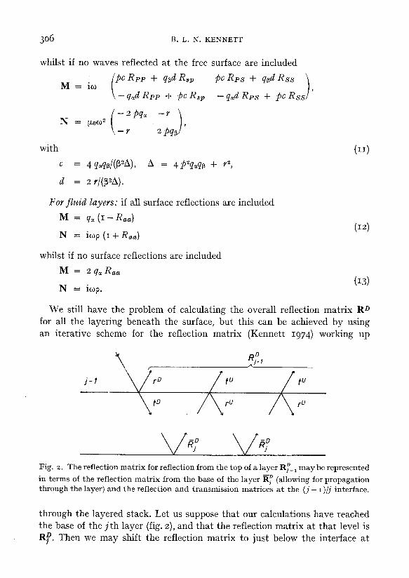
In fig. 4 we compare calculations of 4 s of theoretical seismograms for the elastic case with and without the inclusion of free surface reflections. The time sampling interval used was 4 ms; 2048 time points were employed in the section neglecting surface reflections and 4096 time points for the free surface case. For both sections we used 128 distance points with a distance increment of 55 m, and 12 traces with a plotting increment of IIO m are displayed, thus covering ranges from o to 1210 m. In the absence of the free surface reflections we see that we have been very successful in controlling the numerical problem of aliasing. For the case when surface reflections are included we have not been so fortunate and a noticeable low level ripple is superimposed on the seismograms. This aliasing increases slightly with distance since it is amplified when we neutralize the earlier exponential damping. Aliasing effects are much less severe in less reverbative structures and for this particular velocity profile could be reduced by further extending the number of time points or by including attenuation (which is certainly more realistic).
On each of the true amplitude monitor sections in fig. 4 the primary reflec- tions from the interfaces are marked by the solid triangles. A consequence of the w - k windowing is that only the low frequency part of the shallow reflec- tions are faithfully reproduced. The trace at zero range is accurate for all reflections but from each reflection extend numerical arrivals with infinite phase velocity. This effect is most pronounced for the shallowest reflection where the moveout is partially masked because of the lack of high frequency in the reflection. The deeper reflections, particularly those with two way times greater than 2 s, are well represented but still have slight accompanying extraneous numerical energy.
THEORETICAL REFLECTION SEISMOGRAMS 315

316 B. L. N. KENNETT
The records for an elastic medium without free surface reflections are fairly simple, as expected, with little in the way of strong internal multiples. The most prominent of these multiples is that near 3 s marked by the open circle which arises from reverberation within the velocity inversion at 3 km (fig. 3). For the records including the full effect of the free surface all simple surface multiples are marked by open triangles. The majority of the additional arrivals are, however, produced by reflection at depth of the first multiple in the surface layer. These are marked by open squares, and in some cases lead to interesting interference with the primary reflections.
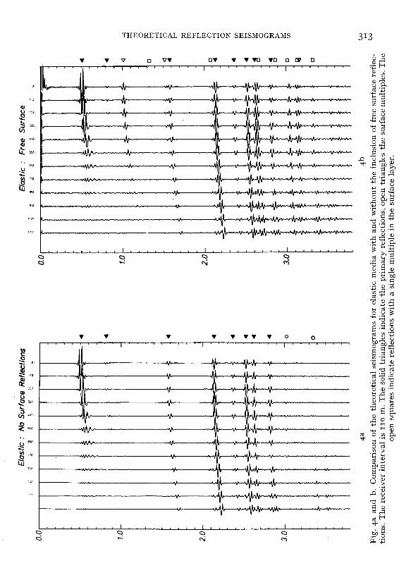
In fig. 5 we compare theoretical records calculated for the same velocity structure, both for elastic layers and for the acoustic approximation. The calculations were performed using the same parameters as those in fig. 4. The elastic case takes very nearly four times as much calculation as the acoustic, since the interfacial reflection coefficients are much more complex in the elastic case and shear waves have to be included in each layer. The purely numerical effects are identical on the two sets of records, and thus we may make direct comparisons for the amplitude of the reflections. Overall the effect of including shear waves is modest. The most obvious converted shear waves appear at around 3.5 s marked by the open pentagon, but com- parison with fig. 4 shows that once free surface multiples are included these would be difficult to discern. However, the amplitudes of the reflections at larger offsets are significantly reduced in the elastic case. It is only at normal and grazing incidence that the P wave reflection coefficients are the same in the elastic and acoustic cases, at intermediate angles they differ particularly at fairly large angles of incidence for which conversion to shear waves can become important. The shear waves thus have an indirect but important role in modifying the nature of the reflection record. This is seen most clearly in fig. 6 where we present a more detailed comparison of the main primary reflections for acoustic and elastic calculations, as in figs. 4 and 5 no time varying gain has been applied along the length of the trace and also no gain has been applied with distance. It is immediately apparent that the reflection amplitudes are reduced for large offsets in the elastic case; at IZOO m for example the amplitude is down by 20 percent for the 2.14 s reflection. Even for the deeper reflections there is a noticeable drop in amplitude between the acoustic and elastic calculations.
It is also apparent from fig. 6 that the reflected pulse may change its shape with increasing offset. This effect arises due to phase shifts introduced in reflection. Such phase shifts may arise at and beyond the critical point for refraction from a thick layer. For a layer comparable to or thinner than the dominant wave length the interference of the primary reflection with interbed multiples becomes the main cause of such phase shifts. Thus, in stacking the

THEORETICAL REFLECTION SEISMOGRAMS 317
6a Elastic
6b Acoustic Fig. 6a and b. Detailed comparison of the main primary reflections.
Geophysical Prospecting 27 21

318 B. L. N. KENNETT
b - :
- 4
_ 4 - 4 - 4
- 4
- a
7a Fig. 7a and b. Comparison of theoretical seismograms for elastic media with and without the inclusion of the attenuation profiles in fig. 3, calculated for a buried source at a
depth of ram, including surface “ghosts”.


320 B. L. N. KENNETT
pulse stretching distortion associated with normal moveout corrections (Dunkin and Levin 1973) may well have been applied to a phase shifted pulse so that there will be degradation of the quality of the stacked pulse.
In fig. 7 we compare the results of seismogram calculations with and without the inclusion of the attenuation profile Q, (z) in fig. 3. We have used an elastic model for each set of traces and the same magnification has been applied to every trace. The source used for this figure was, for variety, a buried source simulating two closely spaced charges at a depth of IO m and “ghosts” are in- cluded. We have included all free surface reflections. A comparison of the records with and without attenuation shows that the main effect is the dramatic loss in amplitudes with two-way time (this would be even more marked with lower Q, values) since no time varying gain has been applied. The mutual interference of the complex source and its ghost leads to the significant shift in energy to greater offsets compared with figs. 4 and 5. For the narrow band of frequencies employed in the source the progressive loss of high frequencies from the pulse due to attenuation (Trorey 1962) is not too marked, but careful examination of the reflected pulses shows a lengthening with increasing two-way time.
In all calculations presented in this paper we have included all internal multiples in each of the layers, since for thick layers the effects of choice of multiples only becomes apparent at very large ranges. For complex velocity profiles, however, the capability of choosing the internal multiples can be of considerable help in disentangling the nature of the reflections.
CONCLUSION
We have illustrated the possibility of calculating effective synthetic seis- mograms for a point source in layered elastic media. Because of the difficulties associated with simulating a line source by the superposition of plane waves such seismograms will always be rather time consuming to compute. However, realistic velocity distributions may be employed in such calculations which is a feature which is not available in the present state of finite difference calculations (Kelly, Ward, Treitel, and Alford rg76), though these may certainly be extended to consider more complex geological situations.
The conventional acoustic approximations for seismic reflection work have been shown to be fully adequate for small offset distances, but even for’com- paratively deep reflections noticeable differences in the amplitude arise at moderate offsets when the effect of shear waves is included. The neglect of shear waves is likely to lead to considerable error when multiples are im- portant. Although some converted shear waves can be seen in the theoretical seismograms calculated for elastic media, it is the modification of interfacial boundary conditions when shear is included that has most effect. Calculations based on the acoustic approximation will overestimate the amplitude of reflec- tions at large offsets.

THEORETICAL REFLECTION SEISMOGRAMS 321
REFERENCES
BARANOV, V. and KUNETZ, G., 1960, Film synthetique avec reflexions multiples; theorie et calcul pratique, Geophys. Prosp. 8, 315-325.
BRAILII, L. W. and YOUNG, G. B., 1976, A computer program for the application of Zoeppritz’s amplitude equations and Knott’s energy equations, Bull. Seism. Sot. Am. 66, 1881-188~.
CERVENTI, V. and RAVINDRA, R., 1971, Theory of Seismic Head Waves, U. of Toronto Press, Toronto.
CLAERBOUT, J. F., 1976, Fundamentals of Geophysical Data Processing, McGraw-Hill, New York.
DUNKIN, J. W. and LEVIN, F. K., 1973, Effect of normal moveout on a seismic pulse, Geophysics 38, 635-642.
FRAZIER, C. W., 1970, Discrete time solution of plane P-SV waves in a plane layered medium, Geophysics 35, 55-70.
FUTTERMAN, W. I., 1962, Dispersive body waves, J. Geophys. Res. 67, 5279-5291. GOUPILLAUD, P. L., 1961, An approach to inverse filtering of near-surface layer effects
from seismic records, Geophysics 26, 754-760. HASKELL, N. A., 1953, The dispersion of surface waves on multilayered media, Bull.
Seism. Sot. Am. 43, 17-34. KELLY, K. R., WARD, R. W., TREITEL, S. and ALFORD, R. M., 1976, Synthetic seismo-
grams: a finite difference approach, Geophysics 41, 2-27. KENNETT, B. L. N., 1974, Reflections, Rays and Reverberations, Bull. Seism. Sot. Am.
64, 1685-1696. KENNETT, B. L. N., 1975, The effect of attenuation on seismograms, Bull. Seism. Sot.
Am. 65. 1643-1651. LUDWIG, W. J., NAFE, J. E. and DRAKE, C. L., 1971, Seismic Refraction is A. E. Maxwell
(ed.) The Sea, vol 4, Interscience, New York, pp 53-84. O'DOHERTY, R. F. and ANSTEY, N. A., 1971, Reflections on Amplitudes, Geophys.
Prosp. 19, 430-458. RICHARDS, P. G. and FRAZIER, C. W., 1976, Scattering of elastic waves from depth
dependent inhomogeneities, Geophysics 41, 441-458. ROSENBAUM, J. H., 1974, Synthetic microseisms: logging in porous formations, Geophysics
39, 14-32. TREITEL, S. and ROBINSON, E. A., 1966, Seismic wave propagation in layered media in
terms of communication theory, Geophysics 31, 17-32. TROREY, A. W., 1962, Theoretical seismograms with frequency and depth dependent
absorption, Geophysics 27, 766-785. WUENSCHEL, P. E., 1960, Seismogram synthesis including multiples and transmission
coefficients, Geophysics 25, 106-129.


![Untitled-1 [rses.anu.edu.au]](https://img.pdfslide.us/doc/110x75/616d79e18bd91c532f64ef86/untitled-1-rsesanueduau.jpg)