Embed Size (px)
Citation preview
461
Abstract
In this paper, at first the attenuation of Lamb waves in three-
layer adhesive joints, including two elastic plates bonded together
by a viscoelastic adhesive layer, is investigated using Global ma-
trix method and then suitable incidence angle is theoretically
calculated to generate low-attenuation Lamb waves using angle
beam transducer. Theoretical boundary value problem in three-
layer adhesive joints with perfect bond and traction-free boundary
conditions on their outer surfaces is solved to find a combination
of frequencies and modes with lowest attenuation. Characteristic
equation is derived by applying continuity and boundary condi-
tions in three-layer joints using Global matrix method. Phase
velocity dispersion curves and attenuation intensity plot in high
and low frequencies are obtained with numerical solution of this
equation by a computer code for a three-layer joint, including an
aluminum repair patch bonded to the aircraft aluminum skin by a
layer of viscoelastic epoxy adhesive. To validate the numerical
solution results of characteristic equation, wave structure curves
are plotted for a special mode in two different frequencies in the
adhesive joint. Also, transducer incidence angle is calculated in
terms of frequency for different modes using theoretical method to
generate Lamb wave modes with low attenuation level by angle
beam transducer. These modes are recognizable by transducers in
inspections with Lamb waves because of low attenuation level.
Keywords
Three-layer adhesive joints; viscoelastic; lamb wave generation;
attenuation; transducer incidence angle.
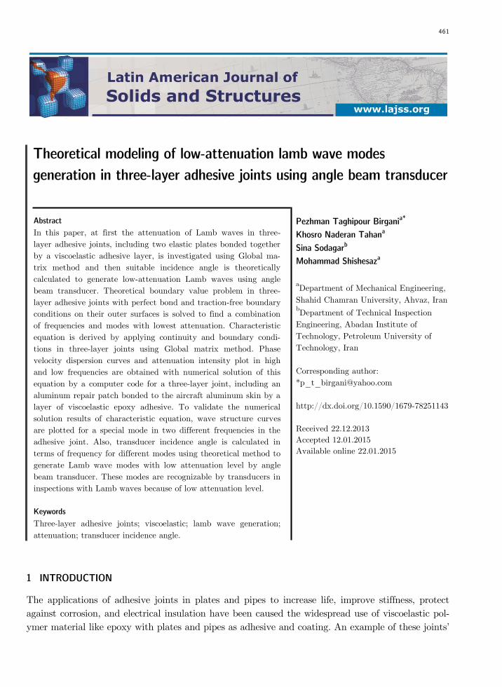
Theoretical modeling of low-attenuation lamb wave modes
generation in three-layer adhesive joints using angle beam transducer
1 INTRODUCTION
The applications of adhesive joints in plates and pipes to increase life, improve stiffness, protect
against corrosion, and electrical insulation have been caused the widespread use of viscoelastic pol-
ymer material like epoxy with plates and pipes as adhesive and coating. An example of these joints’
Pezhman Taghipour Birgania*
Khosro Naderan Tahana
Sina Sodagarb
Mohammad Shishesaza
aDepartment of Mechanical Engineering,
Shahid Chamran University, Ahvaz, Iran bDepartment of Technical Inspection
Engineering, Abadan Institute of
Technology, Petroleum University of
Technology, Iran
Corresponding author:
http://dx.doi.org/10.1590/1679-78251143
Received 22.12.2013
Accepted 12.01.2015
Available online 22.01.2015
462 P. Taghipour Birgani et al. / Theoretical mod. of low-attenuation lamb wave modes generation in three-layer adhesive joints using angle beam transducer
Latin American Journal of Solids and Structures 12 (2015) 461-476
application is a three-layer adhesive joint including an aluminum patch bonded to a surface, like
aircraft aluminum skin, by a viscoelastic epoxy adhesive layer. Repair patches are used to extend
the life of the aircraft. Ultrasonic guided waves are used to inspect these adhesive joints. Lamb
waves have applications in non-destructive inspection of elastic-viscoelastic multi-layer joints and
plates. Some modes of these waves have frequencies with minimum attenuation and are recogniza-
ble in inspection by transducer, and they can also detect the defects in the structures. Low-
attenuation Lamb waves can be produced in multi-layer structures using angle beam transducers for
inspection purposes.
Different studies have been carried out to obtain propagated modes and frequencies in multi-
layer structures (or dispersion curves). Thomson (1950) and Haskell (1953) first investigated the
equations of elastic waves propagation in planar multi-layers with arbitrary number of layers using
transfer matrix method or Thomson-Haskell method. They introduced a transfer matrix that shows
the relationship between displacement and stress in bottom of a layer in comparison to their values
in top of the same layer. One of the difficulties when using transfer matrix method is the instability
of the solution whenever the product of frequency in thickness increases. Dunkin (1965) introduced
delta operator technique to solve this difficulty. Knopoff (1964) was the first to use Global matrix
method to investigate the propagation of elastic waves in multi-layers. In this method a global ma-
trix is used which is derived from putting together the equations of continuity and boundary condi-
tions in all the layers. In investigated studies, the effect of wave energy attenuation in materials is
not taken into consideration.
Watson (1972) obtained the complex roots of the characteristic equation in earth layers and
showed that imaginary part of the wave number is the same as the attenuation in multilayered.
Hosten and Castaings (1993) applied the transfer matrix method in multilayered anisotropic and
damping media. The use of this method in high frequencies is accompanied with numerical instabil-
ity. Castaings and Hosten (1994) applied delta operator technique to improve the stability of trans-
fer matrix method in multilayered anisotropic damping plates. Lowe (1995) presented a summary of
the matrix methods for modeling the propagation of ultrasonic waves in multilayered media. Both
global matrix method and transfer matrix method are used in this study. These techniques can be
used to obtain attenuation and phase velocity dispersion curves in viscoelastic materials. Pan et al.
(1999) investigated the propagation of ultrasonic guided waves in gas pipelines with a thick coating
to choose the suitable mode for inspection. Both the effect of coating thickness and the effect of
coating damping on dispersion curves and mode shapes were investigated and the modes being the
least affected by coating thickness and coating damping were identified. To model the viscoelastic
behavior, the coating is assumed a linear standard solid. Seifried et al. (2002) investigated the prop-
agation of guided waves in multilayered adhesive structures by taking into consideration the low
stiffness and viscoelastic behavior of adhesive layer. To better understand the guided waves behav-
ior and to obtain dispersion curves, they used analytical, experimental and transient FEM simula-
tion methods.
Simonetti (2004) investigated the propagation of Lamb wave in elastic plates coated with viscoe-
lastic materials, and considered the viscoelastic coatings effect on dispersion properties of Lamb
wave propagation in elastic plates. To do this, he used Superposition Partial Bulk Waves (SPBW)
method to model the wave. Simonetti and Cawely (2004) investigated the propagation of shear
P. Taghipour Birgani et al. / Theoretical mod. of low-attenuation lamb wave modes generation in three-layer adhesive joints using angle beam transducer 463
Latin American Journal of Solids and Structures 12 (2015) 461-476
horizontal (SH) waves in an elastic plate coated with viscoelastic material. Material damping causes
an excessive reduction of applied signal in ultrasonic test. In this research, SH wave dispersion
curves for metal plates coated with viscoelastic layers are obtained using SPBW method. Barshing-
er and Rose (2004) investigated the propagation of guided waves in elastic hollow cylinders with
viscoelastic coating using experimental and analytical methods. Wave equation is solved using theo-
retical boundary value problem and the best modes are specified. In this research, Global matrix
method is used to obtain the roots of characteristic equation. It should be noted that in this paper,
the viscoelastic characteristics of the coating are obtained using the transient wave propagation
method. Shorter (2004) investigated the wave propagation in linear viscoelastic laminates using
spectral finite element method or semi-analytical finite element method (SAFE). In this reference,
damping loss factor is estimated for waves in low frequencies, and also stiffness matrix is assumed
to be real. Birgersson et al. (2005) investigated damping loss factor using SAFE method and taking
into consideration the complex stiffness matrix. Bartoli et al. (2006) investigated the wave propaga-
tion in viscoelastic waveguides with an arbitrary cross-section. To model ultrasonic wave propaga-
tion in different waveguides, SAFE method is used. The results of group velocity and phase velocity
dispersion curves (for undamped media), attenuation and energy velocity (for damped media), and
cross-section mode shapes are obtained which are used in non-destructive inspection. The results
accuracy is validated compared to the SPBW method. Marzani et al. (2008) used SAFE method to
analyze wave propagation in viscoelastic axisymmetric waveguides. The results accuracy of the dis-
persion curves is validated compared to the SPBW method. Puthillath and Rose (2010) inspected
the titanium repair patches bonded to the aircraft aluminum skin using ultrasonic guided waves.
They plotted the wave structures using a theoretical method and selected the mode shape with
maximum in-plane displacement for inspection, although they didn’t take into consideration the
effect of material damping.
In the present study, the propagation of Lamb waves in elastic-viscoelastic three-layer joints, in-
cluding two elastic plates bonded together with a layer of viscoelastic adhesive, is investigated using
Global matrix method and considering viscoelastic layer damping effect. Then, the suitable inci-
dence angle is theoretically calculated to generate Lamb wave mode with low attenuation using
angle beam transducer. Also, wave structure is plotted for a specific mode in two different frequen-
cies to verify that continuity and boundary conditions are satisfied and also to explain the attenua-
tion behavior of waves in joints. Adhesive damping causes the excessive reduction of sending signal
amplitude in ultrasonic test; so, modes and frequencies with minimum attenuation should be speci-
fied. Because these waves travel the maximum possible distance in joints and can detect the differ-
ent defects namely interfacial defects.
2 THEORETICAL MODELING OF LAMB WAVES PROPAGATION IN THREE-LAYER ADHESIVE JOINTS
Lamb waves are propagated in thin plate-like mediums in which planar dimensions are far greater
than the thickness of plate and wavelength of the same order with plate thickness (Su and Ye,
2009). Free upper and lower surfaces in plate guide movement of these waves. Lamb waves have
infinite modes and their propagation properties depend on wave entry angle, frequency, and struc-
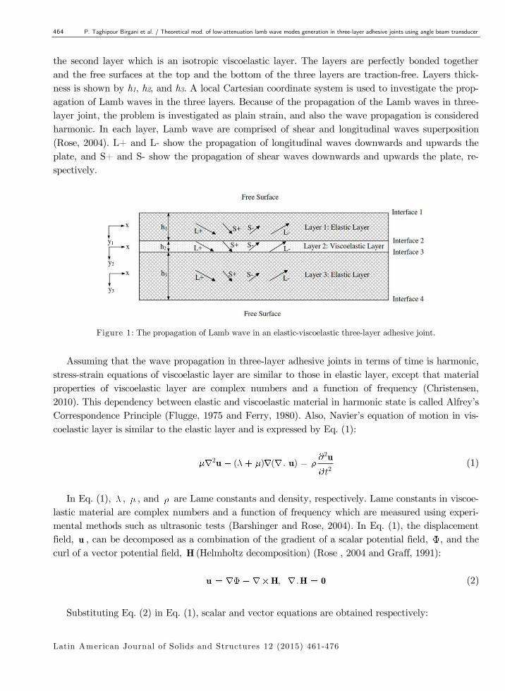
ture geometry. Figure 1 shows Lamb wave propagation in an adhesive joint which is comprised of
three layers. The first and the third layers, which are elastic and isotropic, are bonded together by
464 P. Taghipour Birgani et al. / Theoretical mod. of low-attenuation lamb wave modes generation in three-layer adhesive joints using angle beam transducer
Latin American Journal of Solids and Structures 12 (2015) 461-476
the second layer which is an isotropic viscoelastic layer. The layers are perfectly bonded together
and the free surfaces at the top and the bottom of the three layers are traction-free. Layers thick-
ness is shown by h1, h2, and h3. A local Cartesian coordinate system is used to investigate the prop-
agation of Lamb waves in the three layers. Because of the propagation of the Lamb waves in three-
layer joint, the problem is investigated as plain strain, and also the wave propagation is considered
harmonic. In each layer, Lamb wave are comprised of shear and longitudinal waves superposition
(Rose, 2004). L+ and L- show the propagation of longitudinal waves downwards and upwards the
plate, and S+ and S- show the propagation of shear waves downwards and upwards the plate, re-
spectively.
Figure 1: The propagation of Lamb wave in an elastic-viscoelastic three-layer adhesive joint.
Assuming that the wave propagation in three-layer adhesive joints in terms of time is harmonic,
stress-strain equations of viscoelastic layer are similar to those in elastic layer, except that material
properties of viscoelastic layer are complex numbers and a function of frequency (Christensen,
2010). This dependency between elastic and viscoelastic material in harmonic state is called Alfrey’s
Correspondence Principle (Flugge, 1975 and Ferry, 1980). Also, Navier’s equation of motion in vis-
coelastic layer is similar to the elastic layer and is expressed by Eq. (1):
2
22
( ) ( . )t
uu u (1)
In Eq. (1), , , and are Lame constants and density, respectively. Lame constants in viscoe-
lastic material are complex numbers and a function of frequency which are measured using experi-
mental methods such as ultrasonic tests (Barshinger and Rose, 2004). In Eq. (1), the displacement
field, u , can be decomposed as a combination of the gradient of a scalar potential field, , and the
curl of a vector potential field, H (Helmholtz decomposition) (Rose , 2004 and Graff, 1991):
, .u H H 0 (2)
Substituting Eq. (2) in Eq. (1), scalar and vector equations are obtained respectively:
P. Taghipour Birgani et al. / Theoretical mod. of low-attenuation lamb wave modes generation in three-layer adhesive joints using angle beam transducer 465
Latin American Journal of Solids and Structures 12 (2015) 461-476
2
212 2
1
1 2, C
C t (3)
2
222 2
2
1, C
C t
HH (4)
Eq. (3) shows the propagation of longitudinal wave, and Eq. (4) shows the propagation of trans-
verse wave in structures, and 1C and 2C quantities are longitudinal and shear wave velocities in
medium, respectively. Since Lame constants in viscoelastic material are complex numbers and a
function of frequency, wave velocities are also complex numbers and a function of frequency.
Using Cartesian coordinate system, the potential vector, H , can be defined as the Eq. (5):
x y zH H Hx y zH e e e (5)
Since this problem is assumed as a plain strain, then the equation 0zu z should be sat-
isfied. This happens when xH and yH components equal zero and only zH remains. The scalar
potential function, , should also be a function of x and y .
The solutions of Eqs. (3) and (4) for a harmonic wave propagates along the positive x direction,
are assumed as Eqs. (6) and (7):
( )
( )i kx t
f y e (6)
( )
( )i kx t
z zH h y e (7)
In Eqs. (6) and (7), k and are wave number and angular frequency, respectively.
Substituting Eqs. (6) and (7) in Eqs. (3) and (4) and taking into consideration that the two
components of vector potential function are equal to zero, and after solving the differential equa-
tions, the solutions are obtained as:
2
( ) 2 2( ) ( ) 2
1
,i kx ti y i y
L LA e A e e kC
(8)
2
( ) 2 2( ) ( ) 2
2
,i kx ti y i y
z S SH A e A e e kC
(9)
The solutions of Eqs. (8) and (9) are known as the partial waves solution. The four terms ob-
tained from Eqs. (8) and (9) show the longitudinal waves propagation, L , and transverse waves
propagation, S , upwards and downwards the layer. Constant values show the amplitude of propa-
gated waves; for instance, ( )LA shows the longitudinal wave amplitude propagates towards the
bottom of the layer.
Substituting vector and scalar potential functions from Eqs. (8) and (9) in Eq. (2), the displace-
ment field in adhesive joint is obtained in terms of unknown constants of the shear and longitudinal
wave amplitudes:
{ }
{ }
466 P. Taghipour Birgani et al. / Theoretical mod. of low-attenuation lamb wave modes generation in three-layer adhesive joints using angle beam transducer
Latin American Journal of Solids and Structures 12 (2015) 461-476
( )
( ) ( ) ( ) ( ){ ( ) ( )}i kx ti y i y i y i y
x L L S Su i k A e A e A e A e e 10)
( )
( ) ( ) ( ) ( ){ ( ) ( )}i kx ti y i y i y i y
y L L S Su i A e A e k A e A e e (11) 0zu (12)
Eqs. (10) and (11) can also be expressed as Eqs. (13) and (14):
( )i kx t
x xu U e (13)
( )i kx t
y yu U e (14)
In Eqs. (13) and (14), xU and yU are unattenuated displacement amplitudes.
Using Hooke and strain-displacement relations, stresses in the adhesive joint can be obtained in
terms of the unknown constants of shear and longitudinal wave amplitudes:
( )2 2 2
( ) ( ) ( ) ( ){(2 )( ) 2 ( )}i kx ti y i y i y i y
xx L L S Sk A e A e k A e A e e (15)
( )2 2
( ) ( ) ( ) ( ){( )( ) 2 ( )}i kx ti y i y i y i y
yy L L S Sk A e A e k A e A e e (16)
( )2 2
( ) ( ){( )( )}i kx ti y i y
zz L Lk A e A e e (17)
( )2 2
( ) ( ) ( ) ( ){(2 )( ) ( )( )}i kx ti y i y i y i y
xy L L S Sk A e A e k A e A e e (18) 0, 0xz yz (19)
In order to obtain Lamb waves dispersion curves for elastic-viscoelastic three-layer adhesive
joint, continuity and boundary conditions should be applied.
3 FORMULATION OF CONTINUITY AND BOUNDARY CONDITIOND USING GLOBAL MATRIX METHOD
Global matrix method is a suitable method for formulation of problems concerning multi-layers.
Continuity and boundary conditions are needed for this formulation. Using this method, continuity
and boundary conditions can be shown as matrices and vectors. This method can simultaneously
consider effects of material damping and wave leakage to the environment. In this method a global
matrix is used to describe all the continuity and boundary conditions, and when it comes to numer-
ical stability, it is better than other matrix methods (Lowe, 1995).
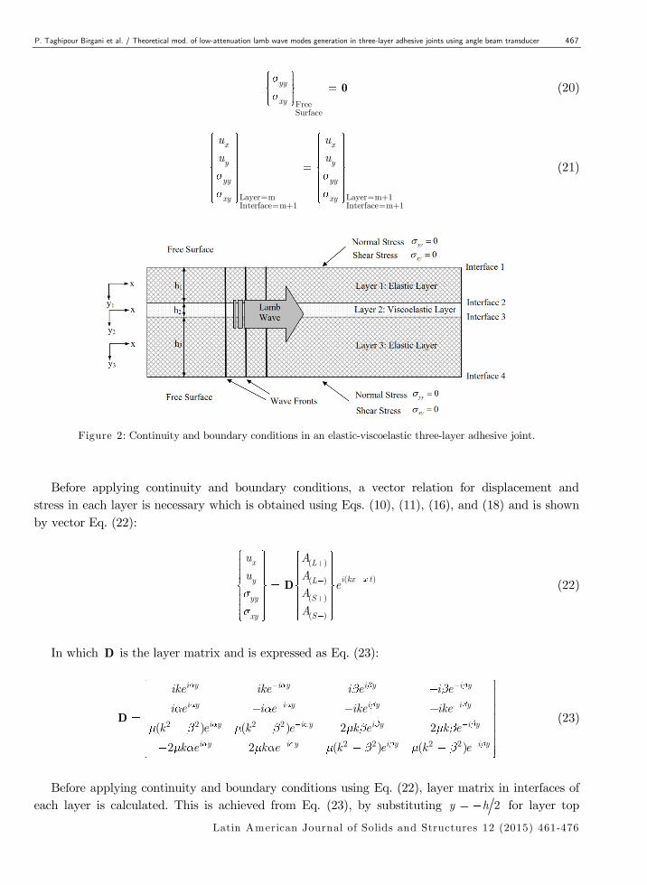
Figure 2 shows the boundary conditions of a three-layer adhesive joint including stress and dis-
placement continuity in layers interfaces and traction-free conditions in up and bottom surfaces of
the elastic-viscoelastic three-layer adhesive joint.
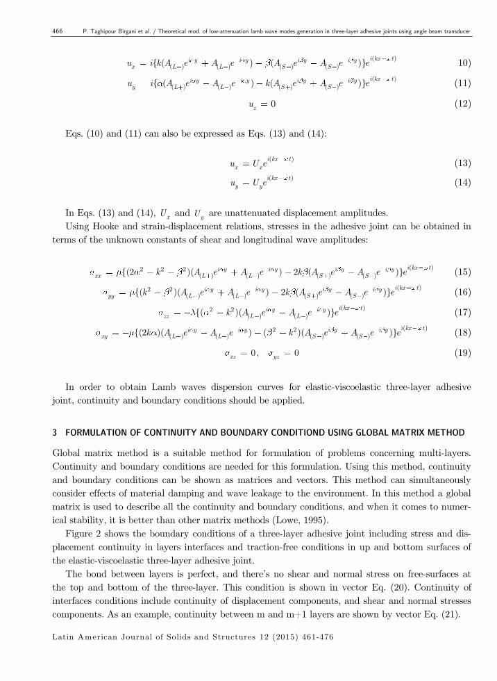
The bond between layers is perfect, and there’s no shear and normal stress on free-surfaces at
the top and bottom of the three-layer. This condition is shown in vector Eq. (20). Continuity of
interfaces conditions include continuity of displacement components, and shear and normal stresses
components. As an example, continuity between m and m+1 layers are shown by vector Eq. (21).
P. Taghipour Birgani et al. / Theoretical mod. of low-attenuation lamb wave modes generation in three-layer adhesive joints using angle beam transducer 467
Latin American Journal of Solids and Structures 12 (2015) 461-476
FreeSurface
yy
xy
0 (20)
Layer=m Layer=m+1Interface=m+1 Interface=m+1
x x
y y
yy yy
xy xy
u u
u u (21)
Figure 2: Continuity and boundary conditions in an elastic-viscoelastic three-layer adhesive joint.
Before applying continuity and boundary conditions, a vector relation for displacement and
stress in each layer is necessary which is obtained using Eqs. (10), (11), (16), and (18) and is shown
by vector Eq. (22):
( )
( )( )
( )
( )
x L
i kx ty L
Syy
Sxy
u A
u Ae
A
A
D (22)
In which D is the layer matrix and is expressed as Eq. (23):
2 2 2 2
2 2 2 2
( ) ( ) 2 2
2 2 ( ) ( )
i y i y i y i y
i y i y i y i y
i y i y i y i y
i y i y i y i y
ike ike i e i e
i e i e ike ike
k e k e k e k e
k e k e k e k e
D (23)
Before applying continuity and boundary conditions using Eq. (22), layer matrix in interfaces of
each layer is calculated. This is achieved from Eq. (23), by substituting 2y h for layer top
468 P. Taghipour Birgani et al. / Theoretical mod. of low-attenuation lamb wave modes generation in three-layer adhesive joints using angle beam transducer
Latin American Journal of Solids and Structures 12 (2015) 461-476
interface, and 2y h for layer bottom interface. These two new layer matrices are shown by tD
and bD , respectively, in which the subscripts t and b show the top and bottom interfaces of layer,
respectively. Local coordinate system is used to derive these matrices, which are shown in Figure 2,
and therefore can be derived for all layers by substituting material properties and thickness.
Now, we express three-layer joint continuity and boundary conditions in the form of a global
matrix which is shown in Eq. (24). mA and 0 vectors in this matrix are shown by Eq. (25):
1 341
1 22
2 33
3 34
( )
( )
t
b t
b t
b
D 0 0A 0
D D 0A 0
0 D DA 0
0 0 D
(24)
( )
( )
( )
( )
0
0,
0
0
L m
L mm
S m
S m
A
A
A
A
A 0 (25)
In Eq. (24) the subscript 34 shows the rows 3 and 4 of the layer matrix.
Global matrix method is a 4 4n n system of equations, in which n is number of layers, and the
global matrix for an elastic-viscoelastic three-layer is 12 12 . In order to the nontrivial solution to
exist, the determinant of global matrix should become zero. This is shown by Eq. (26), which is
called characteristic or dispersion equation of Lamb waves. With the aid of the roots of this equa-
tion, attenuation and phase velocity dispersion curves are plotted in terms of frequency.
1 34
1 2
2 3
3 34
( )
0
( )
t
b t
b t
b
D 0 0
D D 0
0 D D
0 0 D
(26)
4 NUMERICAL SOLUTION METHOD OF CHARACTERISTIC EQUATION
Characteristic equation roots in the three-layer adhesive joint are obtained using numerical solution
method. In characteristic equation, frequency, , is the independent variable, and wave number, k ,
is the dependent variable. The wave number in a desired frequency is obtained by solving this equa-
tion. To find characteristic equation roots, computer code is written in Matlab software. These
roots are shown by curves called dispersion curves.
Finding complex roots of a characteristic equation concerning a three-layer adhesive joint of
which at least one layer is viscoelastic, is a difficult task. In linear viscoelasticity, if harmonic wave
propagation is desired, transverse and longitudinal velocities, and Lame constants of viscoelastic
layer, are complex and a function of frequency. The transverse and longitudinal velocities are calcu-
lated from Eqs. (27) and (28) (Christensen, 2010):
P. Taghipour Birgani et al. / Theoretical mod. of low-attenuation lamb wave modes generation in three-layer adhesive joints using angle beam transducer 469
Latin American Journal of Solids and Structures 12 (2015) 461-476
11
1
1( )
( )1
( )
C i
ic
(27)
22
2
1( )
( )1
( )
C i
ic
(28)
In Eqs. (27) and (28), 1c and 2c are bulk velocities of longitudinal and transverse waves, and 1
and 2 are bulk attenuations of longitudinal and transverse waves of viscoelastic layer. Bulk atten-
uation and velocity values for viscoelastic material can be calculated in terms of frequency, using
experimental test such as ultrasonic test (Barshinger and Rose, 2004).
Before introducing a method for finding the attenuation and phase velocity numerical results,
wave number should be defined in terms of imaginary and real parts. Eq. (29) shows the wave
number as complex (Blanc, 1993):
R I Iph
k k ik ikc
(29)
Eq. (29) enables us to solve the viscoelastic characteristic equation in terms of attenuation, Ik ,
and phase velocity, phc , instead of wave number, k . In this case, the attenuation and phase veloci-
ty dispersion curves are obtained directly.
One solution method for finding the viscoelastic characteristic equation roots is taking into con-
sideration the minimum of characteristic equation absolute value. In this case, the problem becomes
three dimensions in which the characteristic equation absolute value is a function in terms of the
attenuation and phase velocity. In this method we seek to find minimum value of this function. The
main issue in this method is finding all the roots.
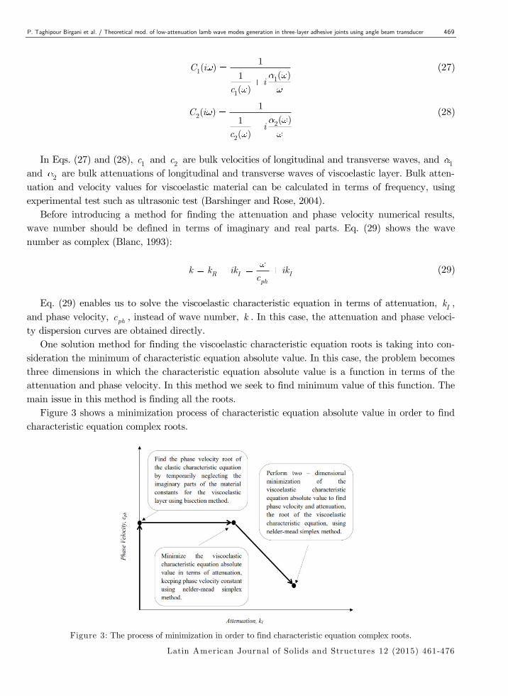
Figure 3 shows a minimization process of characteristic equation absolute value in order to find
characteristic equation complex roots.
Figure 3: The process of minimization in order to find characteristic equation complex roots.
470 P. Taghipour Birgani et al. / Theoretical mod. of low-attenuation lamb wave modes generation in three-layer adhesive joints using angle beam transducer
Latin American Journal of Solids and Structures 12 (2015) 461-476
Using the process shown in Figure 3, a computer code can be written to find characteristic equa-
tion roots. This process can be applied for all desired frequencies, and attenuation and phase veloci-
ty can be obtained in terms of frequency. Attenuation constant can be converted to attenuation in
decibel per length unit, using Eq. (30). This conversion magnifies the attenuation values.
1000( )-1
0 10(dBm ) 20logkIe (30)
5 THEORETICAL MODELING OF LAMB WAVE MODE GENERATION
Different methods exist to generate and receive ultrasonic guided waves. Viktorov (1967) was the
first to evaluate the dispersive properties of Lamb wave he also investigated generation methods of
Lamb waves. He investigated four methods to generate Lamb waves in plates. These methods can
also be used in other structures.
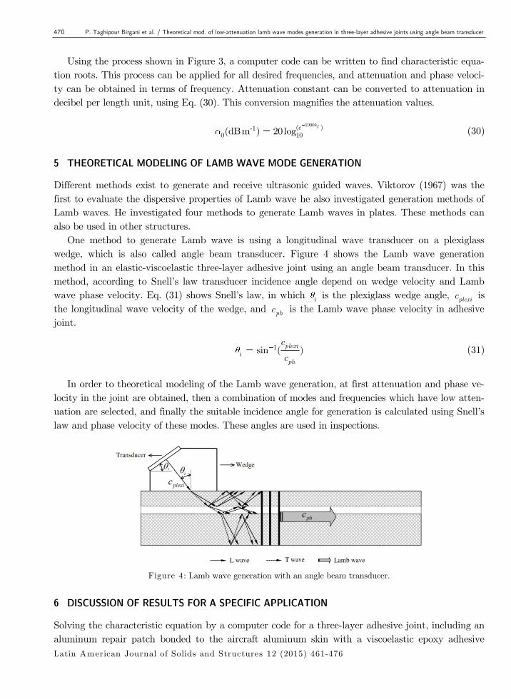
One method to generate Lamb wave is using a longitudinal wave transducer on a plexiglass
wedge, which is also called angle beam transducer. Figure 4 shows the Lamb wave generation
method in an elastic-viscoelastic three-layer adhesive joint using an angle beam transducer. In this
method, according to Snell’s law transducer incidence angle depend on wedge velocity and Lamb
wave phase velocity. Eq. (31) shows Snell’s law, in which i is the plexiglass wedge angle, plexic is
the longitudinal wave velocity of the wedge, and phc is the Lamb wave phase velocity in adhesive
joint.
1sin ( )plexii
ph
c
c (31)
In order to theoretical modeling of the Lamb wave generation, at first attenuation and phase ve-
locity in the joint are obtained, then a combination of modes and frequencies which have low atten-
uation are selected, and finally the suitable incidence angle for generation is calculated using Snell’s
law and phase velocity of these modes. These angles are used in inspections.
Figure 4: Lamb wave generation with an angle beam transducer.
6 DISCUSSION OF RESULTS FOR A SPECIFIC APPLICATION
Solving the characteristic equation by a computer code for a three-layer adhesive joint, including an
aluminum repair patch bonded to the aircraft aluminum skin with a viscoelastic epoxy adhesive
P. Taghipour Birgani et al. / Theoretical mod. of low-attenuation lamb wave modes generation in three-layer adhesive joints using angle beam transducer 471
Latin American Journal of Solids and Structures 12 (2015) 461-476
layer, the attenuation intensity plot and phase velocity dispersion curves in high and low frequen-
cies for this specific application are generated. Also, acceptable attenuation level is calculated for
ultrasonic inspection using a single transducer of the adhesive joint with 200 mm length and suita-
ble modes are selected. Geometric and acoustic properties of elastic-viscoelastic three-layer adhesive
joint can be seen in Table 1. Aluminum and Mereco Epoxy 303 acoustic properties are picked up
from (Barshinger and Rose, 2004).
Wave structure for a mode in two different frequencies is plotted to validate numerical solution
results. Finally, transducer incidence angle is plotted in terms of frequency for different modes, and
suitable wedge angles are selected to generate low-attenuation Lamb wave modes in the adhesive
joint with 200 mm length.
h (mm)
-3(gcm )
2 -1(s km )
2c -1(kms )
1 -1(s km )
1c -1(kms ) Material Layer
1.6 2.7 - 3.13 - 6.35 Aluminum 1
0.66 1.08 0.0201 0.99 0.0070 2.39 Mereco 303 Epoxy 2
3.175 2.7 - 3.13 - 6.35 Aluminum 3
Table 1: Geometric and acoustic properties of an elastic-viscoelastic three-layer adhesive joint.
6.1 Phase velocity dispersion curves and attenuation intensity plot
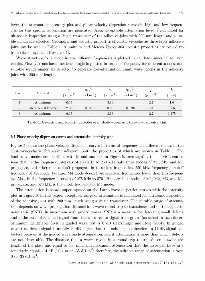
Figure 5 shows the phase velocity dispersion curves in terms of frequency for different modes in the
elastic-viscoelastic three-layer adhesive joint, the properties of which are shown in Table 1. The
lamb wave modes are identified with M and numbers in Figure 5. Investigating this curve it can be
seen that in the frequency intervals of 150 kHz to 250 kHz only three modes of M1, M2, and M3
propagate, and other modes don’t propagate in these low frequencies. 250 kHz frequency is cutoff
frequency of M4 mode; because, M4 mode doesn’t propagate in frequencies lower than this frequen-
cy. Also, in the frequency intervals of 275 kHz to 575 kHz only four modes of M1, M2, M3, and M4
propagate, and 575 kHz is the cutoff frequency of M5 mode.
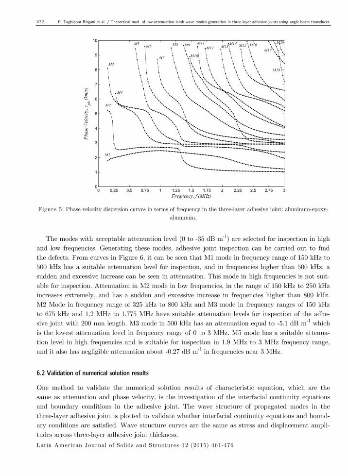
The attenuation is shown superimposed on the Lamb wave dispersion curves with the intensity
plot in Figure 6. In this paper, acceptable range of attenuation is calculated for ultrasonic inspection
of the adhesive joint with 200 mm length using a single transducer. The suitable range of attenua-
tion depends on wave propagation distance in a wave round-trip to transducer and on the signal to
noise ratio (SNR). In inspection with guided waves, SNR is a measure for detecting small defects
and is the ratio of reflected signal from defects to return signal from grains (as noise) to transducer.
Minimum identifiable SNR in guided wave test is 6 dB (Barshinger and Rose, 2004). In guided
wave test, defect signal is usually 20 dB higher than the noise signal; therefore, a 14 dB signal can
be lost because of the guided wave mode attenuation, and if attenuation is more than which, defects
are not detectable. The distance that a wave travels in a round-trip to transducer is twice the
length of the plate and equal to 400 mm, and maximum attenuation that the wave can have in a
round-trip equals -14 dB / 0.4 m or -35 dB m-1; therefore, the suitable range of attenuation is from
0 to -35 dB m-1.
472 P. Taghipour Birgani et al. / Theoretical mod. of low-attenuation lamb wave modes generation in three-layer adhesive joints using angle beam transducer
Latin American Journal of Solids and Structures 12 (2015) 461-476
Figure 5: Phase velocity dispersion curves in terms of frequency in the three-layer adhesive joint: aluminum-epoxy-
aluminum.
The modes with acceptable attenuation level (0 to -35 dB m-1) are selected for inspection in high
and low frequencies. Generating these modes, adhesive joint inspection can be carried out to find
the defects. From curves in Figure 6, it can be seen that M1 mode in frequency range of 150 kHz to
500 kHz has a suitable attenuation level for inspection, and in frequencies higher than 500 kHz, a
sudden and excessive increase can be seen in attenuation. This mode in high frequencies is not suit-
able for inspection. Attenuation in M2 mode in low frequencies, in the range of 150 kHz to 250 kHz
increases extremely, and has a sudden and excessive increase in frequencies higher than 800 kHz.
M2 Mode in frequency range of 325 kHz to 800 kHz and M3 mode in frequency ranges of 150 kHz
to 675 kHz and 1.2 MHz to 1.775 MHz have suitable attenuation levels for inspection of the adhe-
sive joint with 200 mm length. M3 mode in 500 kHz has an attenuation equal to -5.1 dB m-1 which
is the lowest attenuation level in frequency range of 0 to 3 MHz. M5 mode has a suitable attenua-
tion level in high frequencies and is suitable for inspection in 1.9 MHz to 3 MHz frequency range,
and it also has negligible attenuation about -0.27 dB m-1 in frequencies near 3 MHz.
6.2 Validation of numerical solution results
One method to validate the numerical solution results of characteristic equation, which are the
same as attenuation and phase velocity, is the investigation of the interfacial continuity equations
and boundary conditions in the adhesive joint. The wave structure of propagated modes in the
three-layer adhesive joint is plotted to validate whether interfacial continuity equations and bound-
ary conditions are satisfied. Wave structure curves are the same as stress and displacement ampli-
tudes across three-layer adhesive joint thickness.
P. Taghipour Birgani et al. / Theoretical mod. of low-attenuation lamb wave modes generation in three-layer adhesive joints using angle beam transducer 473
Latin American Journal of Solids and Structures 12 (2015) 461-476
Figure 6: Variation of the attenuation superimposed over the Lamb wave dispersion curves for the three-layer adhe-
sive joint: aluminum-epoxy-aluminum.
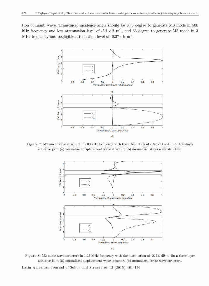
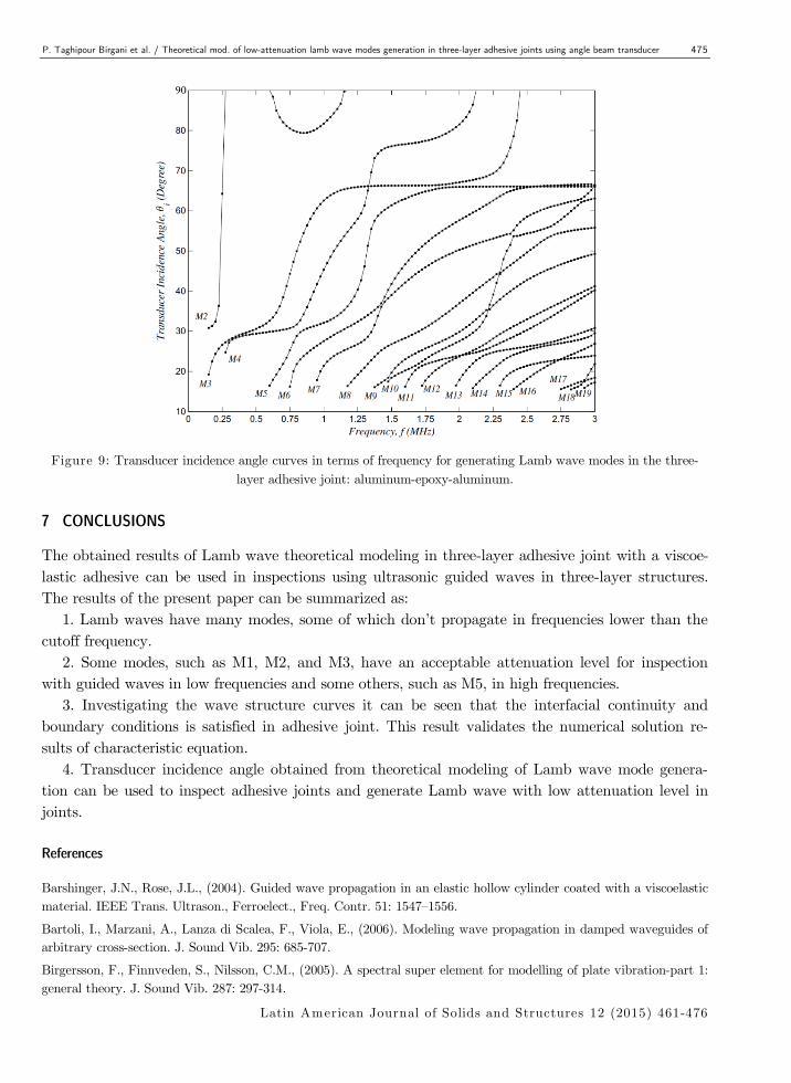
The curve in Figure 7 is the M2 mode wave structure in 500 kHz frequency with an attenuation
of -13.5 dB m-1. As the Figure 7 shows, shear and normal stresses don’t exist in free surfaces at the
top and bottom of the three layers; also, interfacial continuity conditions including continuity of
shear and normal stresses and displacement components, are satisfied. M2 mode wave structure in
1.25 MHz frequency with the attenuation of -222.8 dB m-1 is also plotted in the curves of Figure 8,
in which continuity and boundary conditions are also satisfied. Because attenuation level is high in
wave structure curve of Figure 8, most of the displacement exists in the viscoelastic layer.
6.3 Transducer incidence angles to generate low-attenuation Lamb wave modes
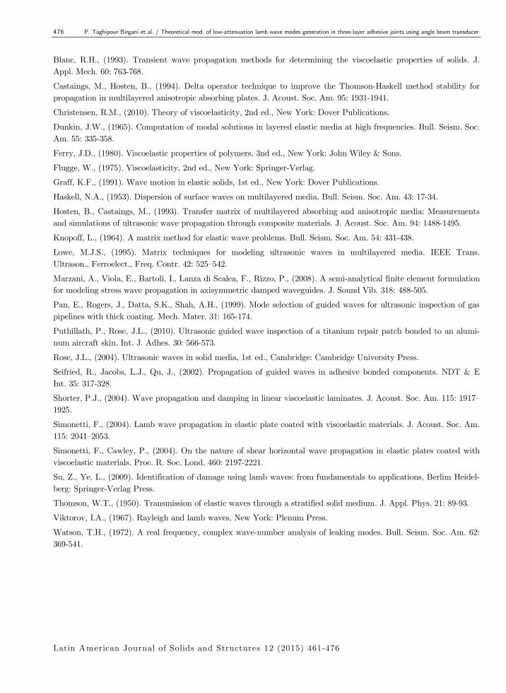
In this section, at first the transducer incidence angle curves in terms of frequency for generating
lamb wave modes in the three-layer adhesive joint is plotted using Eq. (31) and phase velocity val-
ues, these curves are shown in Figure 9. Then the suitable incidence angles are specified to generate
low-attenuation modes by transducer. Investigating Figure 9 it can be seen that the incidence an-
gles for generating some modes such as M1 mode don’t exist, the generation of which is impossible
by the transducer for all the frequency ranges. M2 mode has a low attenuation level and a suitable
incidence angle for inspection in 150 kHz to 200 kHz and 650 kHz to 800 kHz frequency ranges. To
generate this mode in 200 kHz frequency with low attenuation level of -7.34 dB m-1, the transducer
incidence angle should be 32.4 degree. Simultaneously investigating the attenuation values and
transducer incidence angle it can be seen that M3 mode in 150 kHz to 675 kHz frequency range, M4
mode in 300 kHz to 725 kHz frequency range, and M5 mode in 875 kHz to 1.075 MHz and 1.9 MHz
to 3 MHz frequency ranges have low attenuation level and suitable incidence angle for the genera-
474 P. Taghipour Birgani et al. / Theoretical mod. of low-attenuation lamb wave modes generation in three-layer adhesive joints using angle beam transducer
Latin American Journal of Solids and Structures 12 (2015) 461-476
tion of Lamb wave. Transducer incidence angle should be 30.6 degree to generate M3 mode in 500
kHz frequency and low attenuation level of -5.1 dB m-1, and 66 degree to generate M5 mode in 3
MHz frequency and negligible attenuation level of -0.27 dB m-1.
Figure 7: M2 mode wave structure in 500 kHz frequency with the attenuation of -13.5 dB m-1 in a three-layer
adhesive joint (a) normalized displacement wave structure (b) normalized stress wave structure.
Figure 8: M2 mode wave structure in 1.25 MHz frequency with the attenuation of -222.8 dB m-1in a three-layer
adhesive joint (a) normalized displacement wave structure (b) normalized stress wave structure.
P. Taghipour Birgani et al. / Theoretical mod. of low-attenuation lamb wave modes generation in three-layer adhesive joints using angle beam transducer 475
Latin American Journal of Solids and Structures 12 (2015) 461-476
Figure 9: Transducer incidence angle curves in terms of frequency for generating Lamb wave modes in the three-
layer adhesive joint: aluminum-epoxy-aluminum.
7 CONCLUSIONS
The obtained results of Lamb wave theoretical modeling in three-layer adhesive joint with a viscoe-
lastic adhesive can be used in inspections using ultrasonic guided waves in three-layer structures.
The results of the present paper can be summarized as:
1. Lamb waves have many modes, some of which don’t propagate in frequencies lower than the
cutoff frequency.
2. Some modes, such as M1, M2, and M3, have an acceptable attenuation level for inspection
with guided waves in low frequencies and some others, such as M5, in high frequencies.
3. Investigating the wave structure curves it can be seen that the interfacial continuity and
boundary conditions is satisfied in adhesive joint. This result validates the numerical solution re-
sults of characteristic equation.
4. Transducer incidence angle obtained from theoretical modeling of Lamb wave mode genera-
tion can be used to inspect adhesive joints and generate Lamb wave with low attenuation level in
joints.
References
Barshinger, J.N., Rose, J.L., (2004). Guided wave propagation in an elastic hollow cylinder coated with a viscoelastic
material. IEEE Trans. Ultrason., Ferroelect., Freq. Contr. 51: 1547–1556.
Bartoli, I., Marzani, A., Lanza di Scalea, F., Viola, E., (2006). Modeling wave propagation in damped waveguides of
arbitrary cross-section. J. Sound Vib. 295: 685-707.
Birgersson, F., Finnveden, S., Nilsson, C.M., (2005). A spectral super element for modelling of plate vibration-part 1:
general theory. J. Sound Vib. 287: 297-314.
476 P. Taghipour Birgani et al. / Theoretical mod. of low-attenuation lamb wave modes generation in three-layer adhesive joints using angle beam transducer
Latin American Journal of Solids and Structures 12 (2015) 461-476
Blanc, R.H., (1993). Transient wave propagation methods for determining the viscoelastic properties of solids. J.
Appl. Mech. 60: 763-768.
Castaings, M., Hosten, B., (1994). Delta operator technique to improve the Thomson-Haskell method stability for
propagation in multilayered anisotropic absorbing plates. J. Acoust. Soc. Am. 95: 1931-1941.
Christensen, R.M., (2010). Theory of viscoelasticity, 2nd ed., New York: Dover Publications.
Dunkin, J.W., (1965). Computation of modal solutions in layered elastic media at high frequencies. Bull. Seism. Soc.
Am. 55: 335-358.
Ferry, J.D., (1980). Viscoelastic properties of polymers, 3nd ed., New York: John Wiley & Sons.
Flugge, W., (1975). Viscoelasticity, 2nd ed., New York: Springer-Verlag.
Graff, K.F., (1991). Wave motion in elastic solids, 1st ed., New York: Dover Publications.
Haskell, N.A., (1953). Dispersion of surface waves on multilayered media. Bull. Seism. Soc. Am. 43: 17-34.
Hosten, B., Castaings, M., (1993). Transfer matrix of multilayered absorbing and anisotropic media: Measurements
and simulations of ultrasonic wave propagation through composite materials. J. Acoust. Soc. Am. 94: 1488-1495.
Knopoff, L., (1964). A matrix method for elastic wave problems. Bull. Seism. Soc. Am. 54: 431-438.
Lowe, M.J.S., (1995). Matrix techniques for modeling ultrasonic waves in multilayered media. IEEE Trans.
Ultrason., Ferroelect., Freq. Contr. 42: 525–542.
Marzani, A., Viola, E., Bartoli, I., Lanza di Scalea, F., Rizzo, P., (2008). A semi-analytical finite element formulation
for modeling stress wave propagation in axisymmetric damped waveguides. J. Sound Vib. 318: 488-505.
Pan, E., Rogers, J., Datta, S.K., Shah, A.H., (1999). Mode selection of guided waves for ultrasonic inspection of gas
pipelines with thick coating. Mech. Mater. 31: 165-174.
Puthillath, P., Rose, J.L., (2010). Ultrasonic guided wave inspection of a titanium repair patch bonded to an alumi-
num aircraft skin. Int. J. Adhes. 30: 566-573.
Rose, J.L., (2004). Ultrasonic waves in solid media, 1st ed., Cambridge: Cambridge University Press.
Seifried, R., Jacobs, L.J., Qu, J., (2002). Propagation of guided waves in adhesive bonded components. NDT & E
Int. 35: 317-328.
Shorter, P.J., (2004). Wave propagation and damping in linear viscoelastic laminates. J. Acoust. Soc. Am. 115: 1917–
1925.
Simonetti, F., (2004). Lamb wave propagation in elastic plate coated with viscoelastic materials. J. Acoust. Soc. Am.
115: 2041–2053.
Simonetti, F., Cawley, P., (2004). On the nature of shear horizontal wave propagation in elastic plates coated with
viscoelastic materials. Proc. R. Soc. Lond. 460: 2197-2221.
Su, Z., Ye, L., (2009). Identification of damage using lamb waves: from fundamentals to applications, Berlim Heidel-
berg: Springer-Verlag Press.
Thomson, W.T., (1950). Transmission of elastic waves through a stratified solid medium. J. Appl. Phys. 21: 89-93.
Viktorov, I.A., (1967). Rayleigh and lamb waves, New York: Plenum Press.
Watson, T.H., (1972). A real frequency, complex wave-number analysis of leaking modes. Bull. Seism. Soc. Am. 62:
369-541.