Embed Size (px)
Citation preview
Theoretical and Experimental Analysis of the Short Circuit Current Components
in Salient Pole Synchronous Generators
Laura L. Juárez-Caltzontzin, Gustavo Trinidad-Hernández, Tomás I. Asiaín-Olivares and Daniel Ruiz-Vega
Graduate Program in Electrical Engineering, SEPI-ESIMEZ-IPN U.P. “Adolfo López Mateos” Edificio Z-4 1er piso, C.P. 07738
México D. F., MEXICO Tel: +52 55 57 29 6000 ext. 54626, fax: ext 54218, email: [email protected]
Abstract. This paper presents a theoretical and experimental analysis of the short circuit current produced by a salient pole synchronous generator using the experimental data and parameters from a micro machine simulator. Basics of synchronous machine short circuit currents and differences between the current components of salient pole and round rotor machines are explained by means of an IEEE standard procedure [1] which is also useful to determine the dynamic parameters of the synchronous generators. This task is performed by a MATLAB® computer program developed in an undergraduate thesis work [2], which extracts the components from measured data and computes the dynamic parameters from the conventional short circuit test. These results are used to set up an experiment which is intended to show last year undergraduate, as well as graduate power system engineering students these concepts, which are very important to understand synchronous machine transient behavior and power system simulation of short circuits. Key words Synchronous Generator, Short Circuit, Salient Pole Machines, Micro Machine Laboratory. 1. Introduction Most of the faults that occur in a real power system are non symmetric. However, the study of symmetric three phase faults is important because, despite the fact that its occurrence is so rare, it is more severe from the power system transient stability point of view than unbalanced short circuits. In addition, this study is useful to obtain synchronous machine dynamic parameters [1] and to understand the transient behavior of electric power systems under the occurrence of a short circuit. This is the reason this paper presents a detailed analysis of the short circuit current components of salient pole synchronous machines, and outlines its main differences with the ones of round rotor synchronous machines, using the test results from a micro machine network and a digital computer program developed in [2] and based in [1]. These tools are used to set up an experiment which is intended to show last year undergraduate, as well as graduate electrical engineering students these concepts.
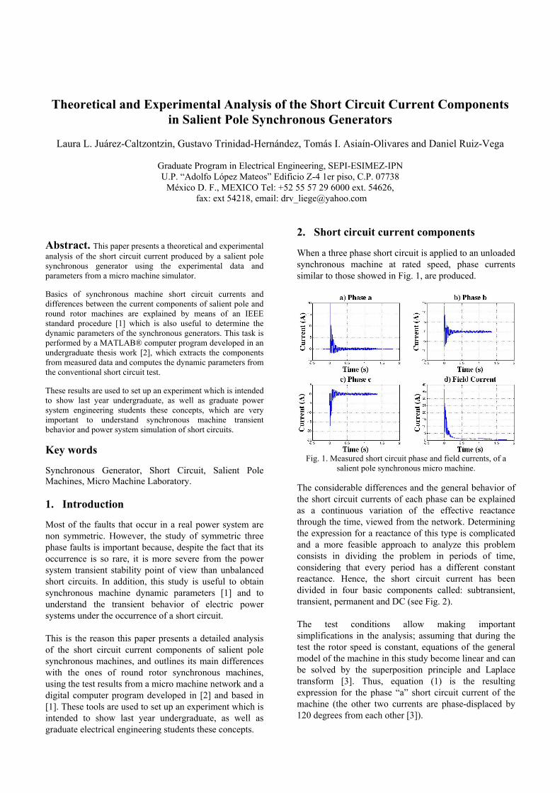
2. Short circuit current components When a three phase short circuit is applied to an unloaded synchronous machine at rated speed, phase currents similar to those showed in Fig. 1, are produced.
Fig. 1. Measured short circuit phase and field currents, of a
salient pole synchronous micro machine. The considerable differences and the general behavior of the short circuit currents of each phase can be explained as a continuous variation of the effective reactance through the time, viewed from the network. Determining the expression for a reactance of this type is complicated and a more feasible approach to analyze this problem consists in dividing the problem in periods of time, considering that every period has a different constant reactance. Hence, the short circuit current has been divided in four basic components called: subtransient, transient, permanent and DC (see Fig. 2). The test conditions allow making important simplifications in the analysis; assuming that during the test the rotor speed is constant, equations of the general model of the machine in this study become linear and can be solved by the superposition principle and Laplace transform [3]. Thus, equation (1) is the resulting expression for the phase “a” short circuit current of the machine (the other two currents are phase-displaced by 120 degrees from each other [3]).
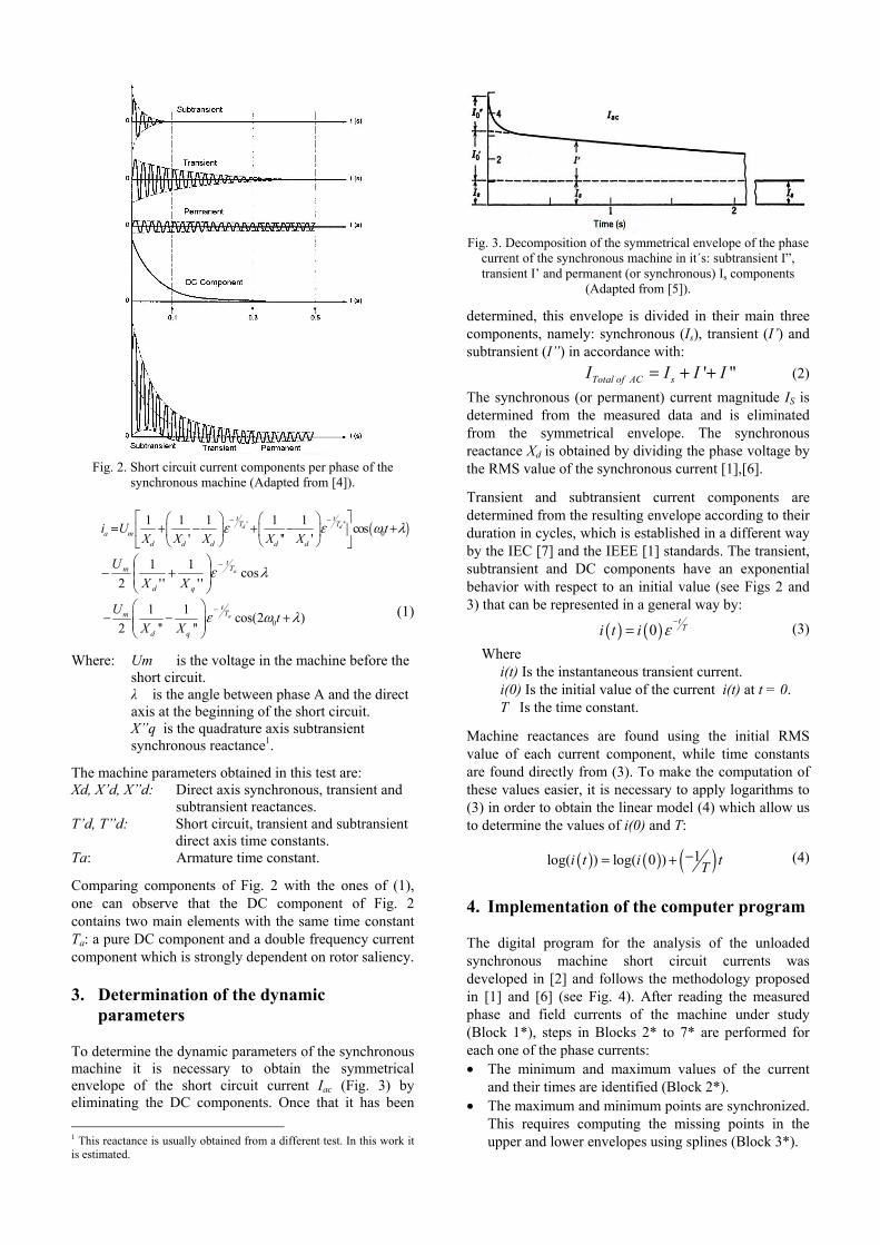
Fig. 2. Short circuit current components per phase of the
synchronous machine (Adapted from [4]).
( )' ''0
1 1 1 1 1 cos' '' '
d dt tT T
a md d d d d
i U tX X X X X
ε ε ω λ− −⎡ ⎤⎛ ⎞ ⎛ ⎞
= + − + − +⎢ ⎥⎜ ⎟ ⎜ ⎟⎝ ⎠ ⎝ ⎠⎣ ⎦
λε cos''
1''
12
aTt
qd
m
XXU −
⎟⎟⎠
⎞⎜⎜⎝
⎛+−
01 1 cos(2 )
2 '' ''a
tTm
d q
U tX X
ε ω λ−⎛ ⎞
− − +⎜ ⎟⎜ ⎟⎝ ⎠
(1)
Where: Um is the voltage in the machine before the short circuit. λ is the angle between phase A and the direct axis at the beginning of the short circuit. X”q is the quadrature axis subtransient synchronous reactance1.
The machine parameters obtained in this test are: Xd, X’d, X”d: Direct axis synchronous, transient and
subtransient reactances. T’d, T”d: Short circuit, transient and subtransient
direct axis time constants. Ta: Armature time constant.
Comparing components of Fig. 2 with the ones of (1), one can observe that the DC component of Fig. 2 contains two main elements with the same time constant Ta: a pure DC component and a double frequency current component which is strongly dependent on rotor saliency. 3. Determination of the dynamic
parameters To determine the dynamic parameters of the synchronous machine it is necessary to obtain the symmetrical envelope of the short circuit current Iac (Fig. 3) by eliminating the DC components. Once that it has been 1 This reactance is usually obtained from a different test. In this work it is estimated.
Fig. 3. Decomposition of the symmetrical envelope of the phase
current of the synchronous machine in it´s: subtransient I”, transient I’ and permanent (or synchronous) Is components
(Adapted from [5]).
determined, this envelope is divided in their main three components, namely: synchronous (Is), transient (I’) and subtransient (I”) in accordance with:
' "Total of AC sI I I I= + + (2) The synchronous (or permanent) current magnitude IS is determined from the measured data and is eliminated from the symmetrical envelope. The synchronous reactance Xd is obtained by dividing the phase voltage by the RMS value of the synchronous current [1],[6].
Transient and subtransient current components are determined from the resulting envelope according to their duration in cycles, which is established in a different way by the IEC [7] and the IEEE [1] standards. The transient, subtransient and DC components have an exponential behavior with respect to an initial value (see Figs 2 and 3) that can be represented in a general way by:
( ) ( )0tTi t i ε
−= (3)
Where i(t) Is the instantaneous transient current. i(0) Is the initial value of the current i(t) at t = 0. T Is the time constant.
Machine reactances are found using the initial RMS value of each current component, while time constants are found directly from (3). To make the computation of these values easier, it is necessary to apply logarithms to (3) in order to obtain the linear model (4) which allow us to determine the values of i(0) and T:
( ) ( ) ( )1log( ) log( 0 )i t i tT−= + (4)
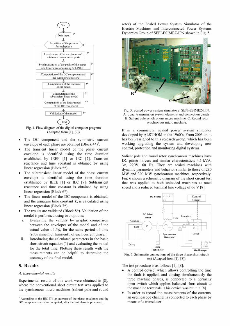
4. Implementation of the computer program The digital program for the analysis of the unloaded synchronous machine short circuit currents was developed in [2] and follows the methodology proposed in [1] and [6] (see Fig. 4). After reading the measured phase and field currents of the machine under study (Block 1*), steps in Blocks 2* to 7* are performed for each one of the phase currents: • The minimum and maximum values of the current
and their times are identified (Block 2*). • The maximum and minimum points are synchronized.
This requires computing the missing points in the upper and lower envelopes using splines (Block 3*).
Start
Data input
Repetition of the process for each phase
Localization of the maximum and minimum current wave peaks
Synchronization of the peaks of the upper and lower envelopes using SPLINES
Computation of the DC component and the symmetric envelope
Computation of the transient linear model
Computation of the subtransient linear model
Computation of the linear model of the DC component
Validation of the model
End
1*
2*
3*
4*
5*
6*
7*
8*
Fig. 4. Flow diagram of the digital computer program
(Adapted from [1], [2]).
• The DC component and the symmetric current envelope of each phase are obtained (Block 4*)2.
• The transient linear model of the phase current envelope is identified using the time duration established by IEEE [1] or IEC [7]. Transient reactance and time constant is obtained by using linear regression (Block 5*).
• The subtransient linear model of the phase current envelope is identified using the time duration established by IEEE [1] or IEC [7]. Subtransient reactance and time constant is obtained by using linear regression (Block 6*).
• The linear model of the DC component is obtained, and the armature time constant Ta is calculated using linear regression (Block 7*).
• The results are validated (Block 8*). Validation of the model is performed using two options:
i. Evaluating the validity by graphic comparison between the envelopes of the model and of the actual value of i(t), for the same period of time (subtransient or transient), of each current phase.
ii. Introducing the calculated parameters in the basic short circuit equation (1) and evaluating the model for the total time. Plotting these results with the measurements can be helpful to determine the accuracy of the final model.
5. Results
A. Experimental results
Experimental results of this work were obtained in [8], where the conventional short circuit test was applied to the synchronous micro machines (salient pole and round 2 According to the IEC [7], an average of the phase envelopes and the DC components are also computed, after the last phase is processed.
rotor) of the Scaled Power System Simulator of the Electric Machines and Interconnected Power Systems Dynamics Group of SEPI-ESIMEZ-IPN shown in Fig. 5.
Fig. 5. Scaled power system simulator at SEPI-ESIMEZ-IPN. A. Load, transmission system elements and connection panels.
B. Salient pole synchronous micro machine. C. Round rotor synchronous micro machine.
It is a commercial scaled power system simulator developed by ALSTHOM in the 1960´s. From 2003 on, it has been assigned to this research group, which has been working upgrading the system and developing new control, protection and monitoring digital systems. Salient pole and round rotor synchronous machines have DC prime movers and similar characteristics: 4.5 kVA, 3φ, 220V, 60 Hz. They are scaled machines with dynamic parameters and behavior similar to those of 280 MW and 300 MW synchronous machines, respectively. Fig. 6 shows a schematic diagram of the short circuit test that was applied to both unloaded machines at rated speed and a reduced terminal line voltage of 66 V [8].
M
Drive
Armature
Field
Optic Tachometer
+-+-
Switch
Oscilloscope
Transducer
ABC
DC Source Control Circuit
FieldDC Prime
mover
SynchronousGenerator
Fig. 6. Schematic connections of the three phase short circuit
test (Adapted from [1], [8]).
The test procedure is as follows [1], [8]: • A control device, which allows controlling the time
the fault is applied, and closing simultaneously the three machine phases, is connected to a normally open switch which applies balanced short circuit to the machine terminals. This device was built in [8].
• In order to record the measurements of the currents, an oscilloscope channel is connected to each phase by means of a transducer.
B A
C
• The machine is started and regulated until it reaches synchronous speed. The prime mover of the synchronous generator is controlled using a DC drive.
• Once that the machine is working at rated speed, the field winding is feeding with a DC source until it compasses 66 V (0.4 p.u.) of rated voltage.
• At the desired time, the three phase short circuit is applied by means of the control device.
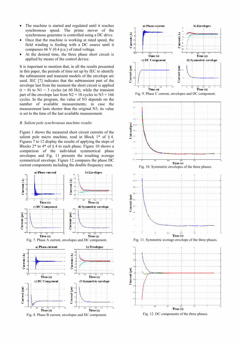
It is important to mention that, in all the results presented in this paper, the periods of time set up by IEC to identify the subtransient and transient models of the envelope are used. IEC [7] indicates that the subtransient part of the envelope last from the moment the short circuit is applied (t = 0) to N1 = 3 cycles (at 60 Hz), while the transient part of the envelope last from N2 = 10 cycles to N3 = 166 cycles. In the program, the value of N3 depends on the number of available measurements; in case the measurement lasts shorter than the original N3, its value is set to the time of the last available measurement. B. Salient pole synchronous machine results Figure 1 shows the measured short circuit currents of the salient pole micro machine, read in Block 1* of § 4. Figures 7 to 12 display the results of applying the steps of Blocks 2* to 4* of § 4 to each phase. Figure 10 shows a comparison of the individual symmetrical phase envelopes and Fig. 11 presents the resulting average symmetrical envelope. Figure 12 compares the phase DC current components including the double frequency ones.
Fig. 7. Phase A current, envelopes and DC component.
Fig. 8. Phase B current, envelopes and DC component.
Fig. 9. Phase C current, envelopes and DC component.
Fig. 10. Symmetric envelopes of the three phases.
Fig. 11. Symmetric average envelope of the three phases.
Fig. 12. DC components of the three phases.

Considering the time periods mentioned in section A of § 5, the subtransient and transient parts of the phase and average symmetrical envelopes are obtained. Figures 13, 14 and 15 show the results of applying the linear model described by (4), to the phase and average subtransient, transient and DC components respectively. These models permit determining subtransient and transient reactances and time constants, and the armature time constant (Blocks 5* to 7* of § 4). The complete set of parameters of the reduced terminal voltage test is displayed in Table I of section D of § 5. According to [1], these parameters are unsaturated, while the ones obtained in the short circuit test at rated terminal voltage, shown in Table II, are saturated.
Fig. 13. Subtransient model .
Fig. 14. Transient model
Fig. 15. Direct current model.
Accuracy of the determined parameters is validated using the two procedures of Block 8* of § 4. In Fig. 16, the exponential models (3) of the subtransient and transient part of the envelope, using the obtained parameters, are compared to the phase and average envelopes determined from measurements.
The second validation consists of evaluating (1) using the determined parameters, and comparing the resulting current with the measurements. In the program of § 4, phase A is always selected to be used in this validation process. It can be observed from (1) that besides the dynamic parameters obtained in this test, two additional values are required to fit (1) to the measured current: the phase angle λ and the value of X”
q. For this case, phase angle was determined, by trial and error, to be λ = 170°. Taking into account that in salient pole synchronous machines X”
q ≈ 1.3 X”d, this value was finally found to be
X”q= 1.6 X”
d. Figure 17 shows the results of the second validation process; it can be observed that in all cases the model fits with great accuracy the measurements. Figure 18 displays the components of the model short circuit current: The symmetrical current, the DC and the double frequency components. It can be observed that, for this salient pole machine, the initial value of the double frequency component (2 A) is approximately 20 % of the initial values of the symmetrical current and of the “pure” DC component (10 A).
Fig. 16. First validation: Comparison of the exponential model
with the measured envelopes of the salient pole machine.
Fig. 17. Second validation: Comparison between the total
calculated (solid line) and measured current (dashed line) of the salient pole machine.
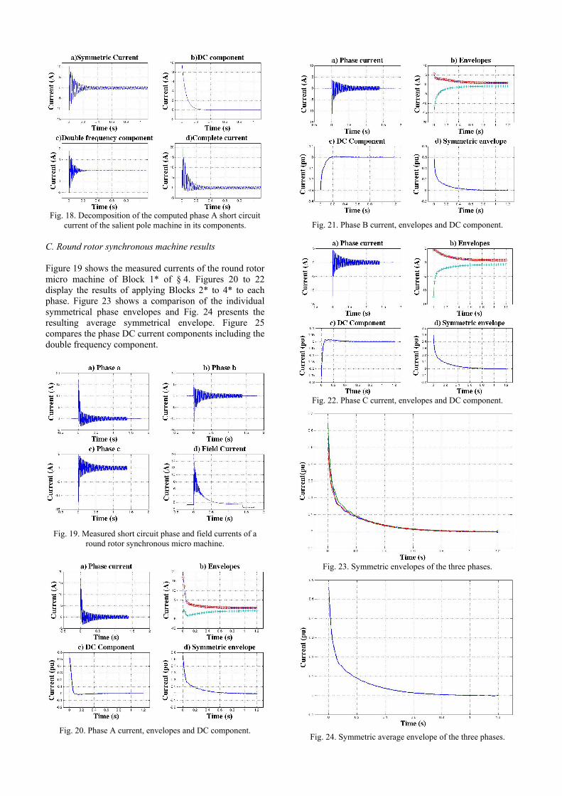
Fig. 18. Decomposition of the computed phase A short circuit
current of the salient pole machine in its components. C. Round rotor synchronous machine results Figure 19 shows the measured currents of the round rotor micro machine of Block 1* of § 4. Figures 20 to 22 display the results of applying Blocks 2* to 4* to each phase. Figure 23 shows a comparison of the individual symmetrical phase envelopes and Fig. 24 presents the resulting average symmetrical envelope. Figure 25 compares the phase DC current components including the double frequency component.
Fig. 19. Measured short circuit phase and field currents of a
round rotor synchronous micro machine.
Fig. 20. Phase A current, envelopes and DC component.
Fig. 21. Phase B current, envelopes and DC component.
Fig. 22. Phase C current, envelopes and DC component.
Fig. 23. Symmetric envelopes of the three phases.
Fig. 24. Symmetric average envelope of the three phases.
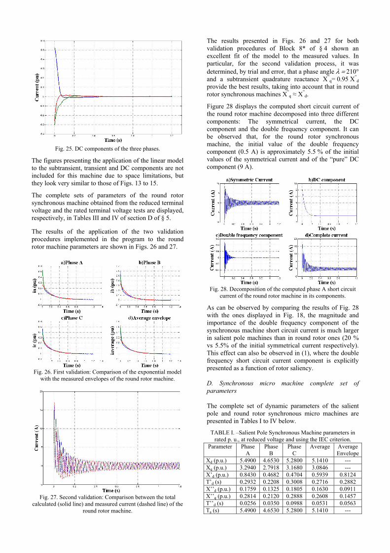
Fig. 25. DC components of the three phases.
The figures presenting the application of the linear model to the subtransient, transient and DC components are not included for this machine due to space limitations, but they look very similar to those of Figs. 13 to 15.
The complete sets of parameters of the round rotor synchronous machine obtained from the reduced terminal voltage and the rated terminal voltage tests are displayed, respectively, in Tables III and IV of section D of § 5. The results of the application of the two validation procedures implemented in the program to the round rotor machine parameters are shown in Figs. 26 and 27.
Fig. 26. First validation: Comparison of the exponential model
with the measured envelopes of the round rotor machine.
Fig. 27. Second validation: Comparison between the total
calculated (solid line) and measured current (dashed line) of the round rotor machine.
The results presented in Figs. 26 and 27 for both validation procedures of Block 8* of § 4 shown an excellent fit of the model to the measured values. In particular, for the second validation process, it was determined, by trial and error, that a phase angle λ = 210° and a subtransient quadrature reactance X”
q= 0.95 X”d
provide the best results, taking into account that in round rotor synchronous machines X”
q ≈ X”d.
Figure 28 displays the computed short circuit current of the round rotor machine decomposed into three different components: The symmetrical current, the DC component and the double frequency component. It can be observed that, for the round rotor synchronous machine, the initial value of the double frequency component (0.5 A) is approximately 5.5 % of the initial values of the symmetrical current and of the “pure” DC component (9 A).
Fig. 28. Decomposition of the computed phase A short circuit
current of the round rotor machine in its components.
As can be observed by comparing the results of Fig. 28 with the ones displayed in Fig. 18, the magnitude and importance of the double frequency component of the synchronous machine short circuit current is much larger in salient pole machines than in round rotor ones (20 % vs 5.5% of the initial symmetrical current respectively). This effect can also be observed in (1), where the double frequency short circuit current component is explicitly presented as a function of rotor saliency. D. Synchronous micro machine complete set of parameters The complete set of dynamic parameters of the salient pole and round rotor synchronous micro machines are presented in Tables I to IV below.
TABLE I. –Salient Pole Synchronous Machine parameters in rated p. u., at reduced voltage and using the IEC criterion.
Parameter Phase A
Phase B
Phase C
Average Average Envelope
Xd (p.u.) 5.4900 4.6530 5.2800 5.1410 --- Xq (p.u.) 3.2940 2.7918 3.1680 3.0846 --- X’d (p.u.) 0.8430 0.4682 0.4704 0.5939 0.8124 T’d (s) 0.2932 0.2208 0.3008 0.2716 0.2882 X’’d (p.u.) 0.1759 0.1325 0.1805 0.1630 0.0911 X’’q (p.u.) 0.2814 0.2120 0.2888 0.2608 0.1457 T’’d (s) 0.0256 0.0350 0.0988 0.0531 0.0563 Ta (s) 5.4900 4.6530 5.2800 5.1410 ---
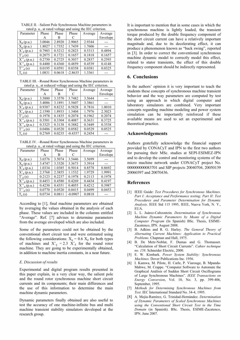
TABLE II. –Salient Pole Synchronous Machine parameters in rated p. u., at rated voltage and using the IEC criterion.
Parameter Phase A
Phase B
Phase C
Average Average Envelope
Xd (p.u.) 3.0046 2.8920 2.9065 2.9344 --- Xq (p.u.) 1.8027 1.7352 1.7439 1.7606 --- X’d (p.u.) 0.7903 0.5212 0.2823 0.5313 0.4894 T’d (s) 0.2075 0.1721 0.1657 0.1818 0.1657 X’’d (p.u.) 0.2750 0.2725 0.3037 0.2837 0.2593 X’’q (p.u.) 0.4400 0.4360 0.4859 0.4539 0.4148 T’’d (s) 0.0195 0.0591 0.0358 0.0381 0.0325 Ta (s) 1.0831 0.0618 -2.8635 1.3361 ---
TABLE III. –Round Rotor Synchronous Machine parameters in
rated p. u., at reduced voltage and using the IEC criterion. Parameter Phase
A Phase
B Phase
C Average Average
EnvelopeXd (p.u.) 3.5880 3.3570 3.7482 3.5644 --- Xq (p.u.) 3.4086 3.1891 3.5607 3.3861 --- X’d (p.u.) 0.9387 0.8232 0.5828 0.7816 1.0010 X’q (p.u.) 2.1590 1.8933 1.3404 1.7976 2.3023 T’d (s) 0.1978 0.1835 0.2074 0.1962 0.2074 X’’d (p.u.) 0.3501 0.3304 0.4087 0.3631 0.3725 X’’q (p.u.) 0.3325 0.3138 0.3882 0.3449 0.3538 T’’d (s) 0.0486 0.0520 0.0582 0.0529 0.0525 Ta (s) 0.2769 0.0235 -0.4357 0.2454 ---
TABLE IV. –Round Rotor Synchronous Machine parameters in
rated p. u., at rated voltage and using the IEC criterion. Parameter Phase
A Phase
B Phase
C Average Average
EnvelopeXd (p.u.) 3.6576 3.5074 3.5446 3.5699 --- Xq (p.u.) 3.4747 3.3320 3.3673 3.3914 --- X’d (p.u.) 1.0334 1.0385 0.5014 0.8578 0.8692 X’q (p.u.) 2.3768 2.3855 1.1532 1.9729 1.9991 T’d (s) 0.2123 0.2237 0.1978 0.2113 0.1978 X’’d (p.u.) 0.4453 0.4580 0.4269 0.4434 0.4197 X’’q (p.u.) 0.4230 0.4351 0.4055 0.4212 0.3987 T’’d (s) 0.0770 0.0520 0.0415 0.0499 0.0453 Ta (s) 0.0734 0.0811 -0.0907 0.0818 --- According to [1], final machine parameters are obtained by averaging the values obtained in the analysis of each phase. These values are included in the columns entitled “Average”. Ref. [7] advises to determine parameters from the average enveloped which are also included.
Some of the parameters could not be obtained by the conventional short circuit test and were estimated using the following considerations: Xq = 0.6 Xd for both types of machines and X’q = 2.3 X’d for the round rotor machine. They are going to be experimentally obtained, in addition to machine inertia constants, in a near future. E. Discussion of results
Experimental and digital program results presented in this paper explain, in a very clear way, the salient pole and the round rotor synchronous machine short circuit currents and its components; their main differences and the use of this information to determine the main machine dynamic parameters.
Dynamic parameters finally obtained are also useful to test the accuracy of one machine-infinite bus and multi machine transient stability simulators developed at the research group.
It is important to mention that in some cases in which the synchronous machine is lightly loaded, the transient torque produced by the double frequency component of the short circuit current can have a relatively important magnitude and, due to its decelerating effect, it can produce a phenomenon known as “back swing”, reported in [3]. In order to correct the conventional synchronous machine dynamic model to correctly model this effect, related to stator transients, the effect of this double frequency component should be indirectly represented. 6. Conclusions In the authors’ opinion it is very important to teach the students these concepts of synchronous machine transient behavior and the way parameters are computed by test using an approach in which digital computer and laboratory simulators are combined. Very important concepts regarding machine modeling and power system simulation can be importantly reinforced if these available means are used to set an experimental and theoretical practice. Acknowledgements Authors gratefully acknowledge the financial support provided by CONACyT and IPN to the first two authors for pursuing their MSc. studies at SEPI-ESIMEZ-IPN and to develop the control and monitoring systems of the micro machine network under CONACyT project No. 000000000083701 and SIP projects 20040704, 20050139 20060397 and 20070436. References [1] IEEE Guide: Test Procedures for Synchronous Machines.
Part I: Acceptance and Performance testing; Part II: Test Procedures and Parameter Determination for Dynamic Analysis. IEEE Std 115 1995, IEEE, Nueva York, N. Y., EUA.
[2] L. L. Juárez-Caltzontzin. Determination of Synchronous Machine Dynamic Parameters by Means of a Digital Computer Program (In Spanish) BSc. Thesis, ESIME-Zacatenco, IPN. August 2008.
[3] B. Adkins and R. G. Harley. The General Theory of Alternating Current Machines: Application to Practical Problems. Chapman and Hall, 1975.
[4] B. De Metz-Noblat, F. Dumas and G. Thomasset. “Calculation of Short Circuit Currents”. Cahier technique no. 158. Schneider Electric, 2000.
[5] E. W. Kimbark. Power System Stability: Synchronous Machines. Dover Publications Inc. 1956.
[6] I. Kamwa, M. Pilote, H. Carle, P. Viarouge, B. Mpanda-Mabwe, M. Crappe. “Computer Software to Automate the Graphical Análisis of Sudden Short Circuit Oscillograms of Large Synchronous Machines”. IEEE Transactions on Energy Conversion, Vol. 10, No. 3, pp. 399-406, September, 1995.
[7] Methods for Determining Synchronous Machines from Test. IEC International Standard No. 34-4, 1995.
[8] A. Mejía-Ramírez, G. Trinidad-Hernández. Determination of Dynamic Parameters of Scaled Synchronous Machines using the Conventional Short Circuit Test in the Time Domain (in Spanish). BSc. Thesis, ESIME-Zacatenco, IPN. June 2007.