Embed Size (px)
Citation preview
The No-Nonsense, Technician Class
License Study Guide(for tests given after July 1, 2014)
Dan Romanchik KB6NU
Copyright © 2014 Daniel M. Romanchik
All rights reserved. No part of this publication may be reproduced, stored in a retrieval system, or transmitted in any form or by any means, electronic, mechanical, recording or otherwise, without the prior written permission of the author.
revision 1.0, 4/30/2014
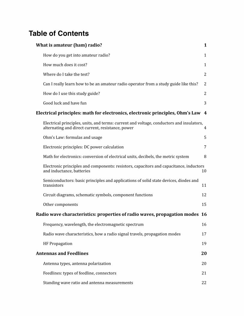
Table of ContentsWhat is amateur (ham) radio? 1
How do you get into amateur radio? 1
How much does it cost? 1
Where do I take the test? 2
Can I really learn how to be an amateur radio operator from a study guide like this? 2
How do I use this study guide? 2
Good luck and have fun 3
Electrical principles: math for electronics, electronic principles, Ohm’s Law 4
Electrical principles, units, and terms: current and voltage, conductors and insulators, alternating and direct current, resistance, power 4
Ohm’s Law: formulas and usage 5
Electronic principles: DC power calculation 7
Math for electronics: conversion of electrical units, decibels, the metric system 8
Electronic principles and components: resistors, capacitors and capacitance, inductors and inductance, batteries 10
Semiconductors: basic principles and applications of solid state devices, diodes and transistors 11
Circuit diagrams, schematic symbols, component functions 12
Other components 15
Radio wave characteristics: properties of radio waves, propagation modes 16
Frequency, wavelength, the electromagnetic spectrum 16
Radio wave characteristics, how a radio signal travels, propagation modes 17
HF Propagation 19
Antennas and Feedlines 20
Antenna types, antenna polarization 20
Feedlines: types of feedline, connectors 21
Standing wave ratio and antenna measurements 22
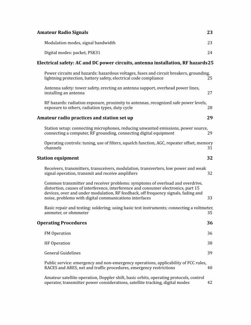
Amateur Radio Signals 23
Modulation modes, signal bandwidth 23
Digital modes: packet, PSK31 24
Electrical safety: AC and DC power circuits, antenna installation, RF hazards 25
Power circuits and hazards: hazardous voltages, fuses and circuit breakers, grounding, lightning protection, battery safety, electrical code compliance 25
Antenna safety: tower safety, erecting an antenna support, overhead power lines, installing an antenna 27
RF hazards: radiation exposure, proximity to antennas, recognized safe power levels, exposure to others, radiation types, duty cycle 28
Amateur radio practices and station set up 29
Station setup: connecting microphones, reducing unwanted emissions, power source, connecting a computer, RF grounding, connecting digital equipment 29
Operating controls: tuning, use of Yilters, squelch function, AGC, repeater offset, memory channels 31
Station equipment 32
Receivers, transmitters, transceivers, modulation, transverters, low power and weak signal operation, transmit and receive ampliYiers 32
Common transmitter and receiver problems: symptoms of overload and overdrive, distortion, causes of interference, interference and consumer electronics, part 15 devices, over and under modulation, RF feedback, off frequency signals, fading and noise, problems with digital communications interfaces 33
Basic repair and testing: soldering; using basic test instruments; connecting a voltmeter, ammeter, or ohmmeter 35
Operating Procedures 36
FM Operation 36
HF Operation 38
General Guidelines 39
Public service: emergency and non-‐emergency operations, applicability of FCC rules, RACES and ARES, net and trafYic procedures, emergency restrictions 40
Amateur satellite operation, Doppler shift, basic orbits, operating protocols, control operator, transmitter power considerations, satellite tracking, digital modes 42
Operating activities: radio direction Yinding, radio control, contests, linking over the Internet, grid locators 43
FCC Rules, descriptions and deUinitions for the Amateur Radio Service, operator and station license responsibilities 44
Amateur Radio Service: purpose and permissible use of the Amateur Radio Service, operator/primary station license grant, where FCC rules are codiYied, basis and purpose of FCC rules, meanings of basic terms used in FCC rules, interference, spectrum management 44
Authorized frequencies: frequency allocations, ITU regions, emission modes, restricted sub-‐bands, spectrum sharing, transmissions near band edges 46
Operator licensing: operator classes; sequential, special event, and vanity call sign systems; international communications; reciprocal operation; station license and licensee; places where the amateur service is regulated by the FCC; name and address on FCC license database; license term; renewal; grace period 47
Authorized and prohibited transmission: communications with other countries, music, exchange of information with other services, indecent language, compensation for use of station, retransmission of other amateur signals, codes and ciphers, sale of equipment, unidentiYied transmissions, broadcasting 49
Control operator and control types: control operator required, eligibility, designation of control operator, privileges and duties, control point, local, automatic and remote control, location of control operator 51
Station identiYication, repeaters, third party communications, club stations, FCC inspection 52
About the Author 53
What is amateur (ham) radio?Amateur radio, also known as ham radio, is a hobby enjoyed by hundreds of thousands of Americans and millions around the world. They enjoy communicating with one another via two-‐way radios and experimenting with antennas and electronic circuits.All kinds of people are amateur radio operators, also known as “hams.” Hams are young, old, men, women, boys, and girls. Kids as young as seven years old have gotten amateur radio licenses, and many hams are active into their 80s and beyond. You never know who you'll run into on the amateur radio bands: young and old, teachers and students, engineers and scientists, doctors and nurses, mechanics and technicians, kings and entertainers.For example, did you know that most of the astronauts sent up to the International Space Station (ISS) in the last Yive to ten years have been licensed radio amateurs? They use the amateur radio station on board the ISS to communicate with school groups all over the world as they are Ylying over.
How do you get into amateur radio?With just a little study, you can learn all you need to know to get a Technician Class license, which is the license class designed for beginners. To get a Technician Class license, you must take a test with 35 multiple-‐choice questions and answer 26 questions correctly. The test covers basic regulations, operating practices, and electrical and electronics theory. Knowing Morse Code is no longer required to get this license, nor any class of license. Technician Class licensees have all amateur radio privileges above 30 MHz, including the very popular 2-‐meter band. Technicians can also operate Morse Code (CW) on portions of the 80m, 40m, 15m, and 10m bands, and voice and digital modes on portions of the 10m band.There are two other license classes: the General Class license and the Amateur Extra Class license. To get a General Class license, you must pass another 35-‐question test; the Amateur Extra Class test has 50 questions. The tests are progressively more difYicult.General Class licensees get phone and digital mode privileges on portions of the 160m, 80m, 60m, 40m, 20m, 15m, and 10m bands. They can also operate CW and digital modes on the 30m band. Amateur Extra licensees have all amateur privileges.
How much does it cost?Basic study materials, such as this study guide, can be had for free, and the license exam fee will be $15 or less. Once you have your Yirst license, most hams Yind it best to start with simple equipment and grow over time. A handheld VHF FM transceiver can be purchased for less than $100 new, and excellent used equipment is often available at low prices. All things considered, the cost to get the Yirst license and radio should be less than $200.
1
Where do I take the test?Amateur radio license examinations are given by Volunteer Examiners, or VEs. VEs are licensed radio amateurs who have been trained to administer amateur radio tests. To Yind out when the VEs in your area will be giving the test go to the American Radio Relay League's (ARRL) website: http://www.arrl.org/Yind-‐an-‐amateur-‐radio-‐license-‐exam-‐session. Using that page, you will be able to search for test sessions that are close to you. If you do not have access to the Internet, you can phone the ARRL at 860-‐594-‐0200.
Can I really learn how to be an amateur radio operator from a study guide like this?Yes and no. This manual will help you get your license, but getting your license is only the beginning. There is still much to learn, and to get the most out of amateur radio, you will have to continually learn new things.This study guide will teach you the answers to the test questions, but will not give you a deep understanding of electronics, radio, or the rules and regulations. That will be up to you after you get your license.I hope that by helping you get your license that you’ll be encouraged to become an active radio amateur and get on the air, participate in public service and emergency communications, join an amateur radio club, and experiment with radios, antennas, and circuits. These are the activities that will really help you learn about radio in depth, and in the end, help you be conYident in your abilities as an amateur radio operator.
How do I use this study guide?First, read through the study guide, and then, take some practice tests. The characters in parentheses —(T5A05), for example—refer to the question number in the Technician Class Exam Question Pool. You will Yind the answers to questions in bold.You can take practice tests by going to the following websites:• AA9PW.com• QRZ.com/hamtest/• eHam.net/exams/• HamExam.org • HamStudy.org• copaseticYlows.appspot.com/hamtestThere are also ham test apps for both iOS and Android tablets:• iOS:
• Amateur Radio Exam Prep (https://itunes.apple.com/us/app/amateur-‐radio-‐exam-‐prep-‐technician/id297951496?mt=8). $4.99
• Ham Radio Exam (https://itunes.apple.com/us/app/ham-‐radio-‐exam-‐tech/id601991935?mt=8). FREE.
• Android:• Ham Radio Study (https://play.google.com/store/apps/details?id=com.tango11.hamstudy)
2
• Ham Test Prep (https://play.google.com/store/apps/details?id=com.iversoft.ham.test.prep&hl=en)
Good luck and have funI hope that you Yind this study guide useful and that you’ll become a radio amateur. Remember that getting your license is just a start, and that you will be continually learning new things.If you have any comments, questions, compliments or complaints, I want to hear from you. E-‐mail me at [email protected]. My goal is to continually reYine this study guide and to continually make it better.Dan Romanchik KB6NU
3
Electrical principles: math for electronics, electronic principles, Ohm’s Law
Electrical principles, units, and terms: current and voltage, conductors and insulators, alternating and direct current, resistance, powerYou don't have to be an electronics engineer to get a Technician Class license, but it does help to know the basics of electricity and some of the units we use in electronics. The most important concepts are current, voltage, resistance, power, and frequency.Voltage is the force that causes electrons to Ylow in a circuit. Voltage is sometimes called electromotive force, or EMF. Voltage is the electrical term for the electromotive force (EMF) that causes electron Ylow. (T5A05) The volt is the basic unit of electromotive force. (T5A11) The letter V is the symbol we use for volts. About 12 volts is the amount of voltage that a mobile transceiver usually requires. (T5A06)Current is the name for the Ylow of electrons in an electric circuit. (T5A03) Electrical current is measured in amperes. (T5A01) Direct current is the name for a current that Ylows only in one direction. (T5A04) Batteries supply direct current, or simply DC.Alternating current is the name for a current that reverses direction on a regular basis. (T5A09) Frequency is the term that describes the number of times per second that an alternating current reverses direction. (T5A12) Alternating current, or AC, is what is available from your home’s wall sockets. Power supplies convert the AC into DC, which is required for most modern amateur radio equipment.Resistance is the term used to describe opposition to current Ylow in a circuit. The basic unit of resistance is the ohm. The Greek letter omega (Ω) is shorthand for ohms.Conductors are materials that conduct electrical current well, or, in other words, have a low resistance. The copper wires that we use to connect a power supply to a radio are good conductors because copper is a good electrical conductor. (T5A07)Insulators are materials that that have a high resistance. They do not conduct electrical current very well. Plastics and glass, for example, are good electrical insulators. (T5A08)The term that describes the rate at which electrical energy is used (or generated) is power. (T5A10) Electrical power is measured in watts. (T5A02) The letter W is the symbol we use for watts.
4
Ohm’s Law: formulas and usage Hams obey Ohm’s Law!Ohm’s Law is the relationship between voltage, current, and the resistance in a DC circuit. When you know any two of these values, you can calculate the third.The most basic equation for Ohm’s Law is E =I ×RIn other words, when you know the current going into a circuit and the resistance of the circuit, the formula used to calculate voltage across the circuit is voltage (E) equals current (I) multiplied by resistance (R). (T5D02)When you know the voltage across a circuit and the current in the circuit, the formula used to calculate resistance in a circuit is resistance (R) equals voltage (E) divided by current (I). (T5D03) We can also write this formula as R =E ÷I
When you know the voltage across a circuit and the resistance of a circuit, the formula used to calculate current in the circuit is current (I) equals voltage (E) divided by resistance (R). (T5D01) This formula is written I =E ÷R
ExamplesThe resistance of a circuit in which a current of 3 amperes Ylows through a resistor connected to 90 volts is 30 ohms. (T5D04) R = E ÷ I = 90 V ÷ 3 A = 30 ΩThe resistance in a circuit for which the applied voltage is 12 volts and the current Ylow is 1.5 amperes is 8 ohms.(T5D05) R = E ÷ I = 12 V ÷ 1.5 A = 8 ΩThe resistance of a circuit that draws 4 amperes from a 12-‐volt source is 3 ohms. (T5D06) R = E ÷ I = 12 V ÷ 4 A = 3 ΩThe current Ylow in a circuit with an applied voltage of 120 volts and a resistance of 80 ohms is 1.5 amperes. (T5D07) I = E ÷ R = 120 V ÷ 80 Ω = 1.5 AThe current Ylowing through a 100-‐ohm resistor connected across 200 volts is 2 amperes. (T5D08) I = E ÷ R = 200 V ÷ 100 Ω = 2 A
The current Ylowing through a 24-‐ohm resistor connected across 240 volts is 10 amperes. (T5D09) I = E ÷ R = 240 V ÷ 24 Ω = 10 A
5
The voltage across a 2-‐ohm resistor if a current of 0.5 amperes Ylows through it is 1 volt. (T5D10) E = I × R = 0.5 A × 2 Ω = 1 V
The voltage across a 10-‐ohm resistor if a current of 1 ampere Ylows through it is 10 volts. (T5D11) E = I × R = 1 A × 10 Ω = 10 VThe voltage across a 10-‐ohm resistor if a current of 2 amperes Ylows through it is 20 volts. (T5D12) E = I × R = 2 A × 10 Ω = 20 V
6
Electronic principles: DC power calculationPower is the rate at which electrical energy is generated or consumed. The formula used to calculate electrical power in a DC circuit is power (P) equals voltage (E) multiplied by current (I). (T5C08) P= E × I
138 watts is the power being used in a circuit when the applied voltage is 13.8 volts DC and the current is 10 amperes. (T5C09) P = E × I = 13.8 V × 10 A = 138 WWhen the applied voltage in a circuit is 12 volts DC and the current is 2.5 amperes, the power being used is 30 watts. (T5C10) P = E × I = 12 V × 2.5 A = 30 WJust as with Ohm’s Law, you can use algebra to come up with other forms of this equation to calculate the voltage if you know the power and the current, or to calculate the current if you know the power and the voltage. The formula to calculate the current, if you know the power and the voltage is I =P÷E
For example, 10 amperes are Ylowing in a circuit when the applied voltage is 12 volts DC and the load is 120 watts. (T5C11) I = P ÷ E = 120 W ÷ 12 V = 10 A
7
Math for electronics: conversion of electrical units, decibels, the metric system When dealing with electrical parameters, such as voltage, resistance, current, and power, we use a set of preYixes to denote various orders of magnitude:• milli-‐ is the preYix we use to denote 1 one-‐thousandth of a quantity. A milliampere, for example, is 1 one-‐thousandth of an ampere, or 0.001 A. Often, the letter m is used instead of the preYix milli-‐. 1 milliampere is, therefore, 1 mA.
• micro-‐ is the preYix we use to denote 1 millionth of a quantity. A microvolt, for example, is 1 millionth of a volt, or 0.000001 V. Often you will see the Greek letter mu, or μ, to denote the preYix micro-‐. 1 microvolt is, therefore, 1 μV.
• pico-‐ is the preYix we use to denote 1 trillionth of a quantity. A picovolt is 1 trillionth of a volt, or 0.000001 μV.
• kilo-‐ is the preYix we use to denote 1 thousand of a quantity. A kilovolt, for example, is 1000 volts. Often, the letter k is used instead of the preYix kilo-‐. 1 kilovolt is, therefore, 1 kV.
• mega-‐ is the preYix we use to denote 1 million of a quantity. A megahertz, for example, is 1 million Hertz. The unit of frequency is the Hertz. (T5C05) It is equal to one cycle per second. Often, the letter M is used instead of the preYix mega-‐. 1 megahertz is, therefore, 1 MHz.
Here are some examples: • 1,500 milliamperes is 1.5 amperes. (T5B01)• Another way to specify a radio signal frequency of 1,500,000 hertz is 1500 kHz. (T5B02)
• One thousand volts are equal to one kilovolt. (T5B03)• One one-millionth of a volt is equal to one microvolt. (T5B04)• 0.5 watts is equivalent to 500 millwatts. (T5B05)• If an ammeter (a meter that meaures current) calibrated in amperes is used to measure a 3000-‐milliampere current, the reading it would show would be 3 amperes. (T5B06)
• If a frequency readout calibrated in megahertz shows a reading of 3.525 MHz, it would show 3525 kHz if it were calibrated in kilohertz. (T5B07)
• 1 microfarad is 1,000,000 picofarads. (T5B08) (Farad is the unit for capacitance.) • 28.400 MHz is equal to 28,400 kHz. (T5B12)• If a frequency readout shows a reading of 2425 MHz, the frequency in GHz is 2.425 GHz. (T5B13)
When dealing with ratios—especially power ratios—we often use decibels (dB). The reason for this is that the decibel scale is a logarithmic scale, meaning that we can talk about large ratios with relatively small numbers. At this point, you don’t need to know the formula used to calculate the ratio in dB, but keep in mind the following values:
• 3 dB is the approximate amount of change, measured in decibels (dB), of a power increase from 5 watts to 10 watts. (T5B09) This is a ratio of 2 to 1.
• −6 dB is the approximate amount of change, measured in decibels (dB), of a power decrease from 12 watts to 3 watts. (T5B10) This is a ration of 4 to 1.
8
• 10 dB is the approximate amount of change, measured in decibels (dB), of a power increase from 20 watts to 200 watts. (T5B11) This is a ratio of 10 to 1.
9
Electronic principles and components: resistors, capacitors and capacitance, inductors and inductance, batteriesA resistor is the electrical component used to oppose the Ylow of current in a DC circuit. (T6A01) Most resistors have a Yixed value, which is speciYied in ohms. Some resistors are variable, that is you can change the resistance of the resistor by turning a shaft or sliding a control back and forth. These variable resistors are called potentiometers. A potentiometer is the type of component that is often used as an adjustable volume control. (T6A02) Resistance is the electrical parameter that is controlled by a potentiometer. (T6A03)The type of electrical component that consists of two or more conductive surfaces separated by an insulator is a capacitor. (T6A05) A capacitor is the electrical component that stores energy in an electric Yield. (T6A04) Capacitance is the ability to store energy in an electric Yield. (T5C01) The farad is the basic unit of capacitance. (T5C02)The type of electrical component that stores energy in a magnetic Yield is an inductor. (T6A06) The electrical component that is usually composed of a coil of wire is an inductor. (T6A07) The ability to store energy in a magnetic Yield is called inductance. (T5C03) The henry is the basic unit of inductance. (T5C04)A switch is the electrical component used to connect or disconnect electrical circuits. (T6A08)A fuse is the electrical component used to protect other circuit components from current overloads. (T6A09)As amateur radio operators, we often use batteries to power our radio equipment. Some types of batteries are rechargeable, while others are not. The battery type that is not rechargeable is the carbon-zinc battery. (T6A11) All of these choices are correct when talking about battery types that are rechargeable (T6A10):• Nickel-‐metal hydride• Lithium-‐ion• Lead-‐acid gel-‐cell
10
Semiconductors: basic principles and applications of solid state devices, diodes and transistors A diode is an electronic component that allows current to Ylow in only one direction. (T6B02) Diodes have only two electrodes. Anode and cathode are the names of the two electrodes of a diode. (T6B09) A semiconductor diode’s cathode lead is usually identiYied with a stripe. (T6B06)Light-‐emitting diodes are a particular type of diode. When current Ylows through them, they emit visible light, making them useful as indicators and as part of digital readouts. The abbreviation “LED” stands for Light Emitting Diode. (T6B07)Transistors are electronic components capable of using a voltage or current signal to control current Ylow. (T6B01) The transistor is a component that can be used as either an electronic switch or ampliYier. (T6B03) Gain is the term that describes a transistor's ability to amplify a signal. (T6B12) The transistor is an electronic component that can amplify signals. (T6B05)A transistor is a component made of three layers of semiconductor material. (T6B04) Bipolar junction transistors have layers that are either P-‐type, which means that it has a positive net charge, or N-‐type, which means it has a net negative charge. Each layer has an electrode, making the transistor a device with three leads. There are two types of bipolar junction transistors: PNP or NPN. A PNP transistor has two P layers, with an N layer sandwiched between them. An NPN transistor has two N layers, with a P layer sandwiched between them. The three electrodes of a PNP or NPN transistor are the emitter, base, and collector. (T6B10)Another type of transistor often found in amateur radio equipment is the Yield-‐effect transistor. The abbreviation “FET” stands for Field Effect Transistor. (T6B08) FETs, like NPN and PNP transistors have three leads. Source, gate, and drain are the three electrodes of a Yield effect transistor. (T6B11)
11
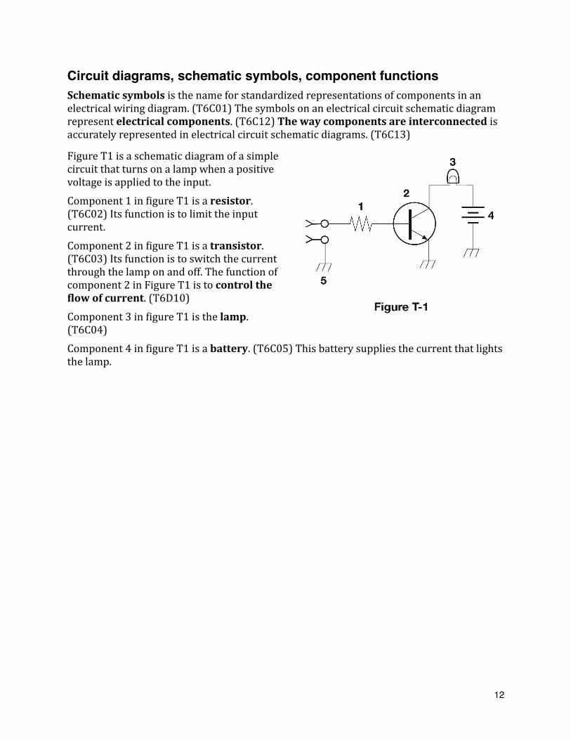
Circuit diagrams, schematic symbols, component functionsSchematic symbols is the name for standardized representations of components in an electrical wiring diagram. (T6C01) The symbols on an electrical circuit schematic diagram represent electrical components. (T6C12) The way components are interconnected is accurately represented in electrical circuit schematic diagrams. (T6C13)
Figure T1 is a schematic diagram of a simple circuit that turns on a lamp when a positive voltage is applied to the input. Component 1 in Yigure T1 is a resistor. (T6C02) Its function is to limit the input current.Component 2 in Yigure T1 is a transistor. (T6C03) Its function is to switch the current through the lamp on and off. The function of component 2 in Figure T1 is to control the Ulow of current. (T6D10) Component 3 in Yigure T1 is the lamp. (T6C04)Component 4 in Yigure T1 is a battery. (T6C05) This battery supplies the current that lights the lamp.
12
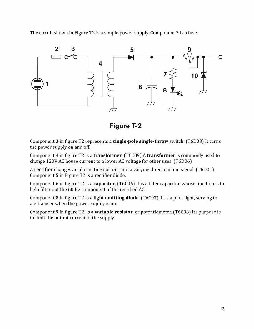
The circuit shown in Figure T2 is a simple power supply. Component 2 is a fuse.
Component 3 in Yigure T2 represents a single-pole single-throw switch. (T6D03) It turns the power supply on and off.Component 4 in Yigure T2 is a transformer. (T6C09) A transformer is commonly used to change 120V AC house current to a lower AC voltage for other uses. (T6D06)A rectiUier changes an alternating current into a varying direct current signal. (T6D01) Component 5 in Figure T2 is a rectiYier diode.Component 6 in Yigure T2 is a capacitor. (T6C06) It is a Yilter capacitor, whose function is to help Yilter out the 60 Hz component of the rectiYied AC.Component 8 in Yigure T2 is a light emitting diode. (T6C07). It is a pilot light, serving to alert a user when the power supply is on.Component 9 in Yigure T2 is a variable resistor, or potentiometer. (T6C08) Its purpose is to limit the output current of the supply.
13
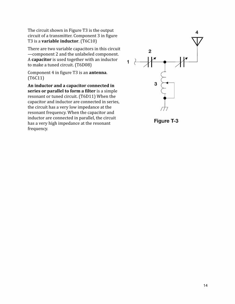
The circuit shown in Figure T3 is the output circuit of a transmitter. Component 3 in Yigure T3 is a variable inductor. (T6C10)There are two variable capacitors in this circuit—component 2 and the unlabeled component. A capacitor is used together with an inductor to make a tuned circuit. (T6D08)Component 4 in Yigure T3 is an antenna. (T6C11)An inductor and a capacitor connected in series or parallel to form a Uilter is a simple resonant or tuned circuit. (T6D11) When the capacitor and inductor are connected in series, the circuit has a very low impedance at the resonant frequency. When the capacitor and inductor are connected in parallel, the circuit has a very high impedance at the resonant frequency.
14
Other componentsThere are many different types of components in modern radio equipment. Below, we will describe the types of components you will need to know about to pass the Technician Class license examination. A relay is a switch controlled by an electromagnet. (T6D02)Meters are devices used to indicate many different values. For example, a meter can be used to display signal strength on a numeric scale. (T6D04) Meters are also used to indicate the output voltage of a power supply, the output power of a transmitter, and many other parameters.Integrated circuit is the name of a device that combines several semiconductors and other components into one package. (T6D09) Integrated circuits may perform either analog or digital functions. One type of analog integrated circuit that is very common is the voltage regulator. A regulator is the type of circuit that controls the amount of voltage from a power supply. (T6D05)An LED is commonly used as a visual indicator. (T6D07) LED is short for light-‐emitting diode. They come in a variety of colors.When connecting electronic assemblies together, we often use cables with one or more conductors. Some of those conductors may have a shield around them that is connected to ground. A common reason to use shielded wire is to prevent coupling of unwanted signals to or from the wire. (T6D12)
15
Radio wave characteristics: properties of radio waves, propagation modes
Frequency, wavelength, the electromagnetic spectrumElectromagnetic is the type of wave that carries radio signals between transmitting and receiving stations. (T3A07) The usual name for electromagnetic waves that travel through space is radio waves. (T5C07) As the name would imply, the two components of a radio wave are electric and magnetic Uields. (T3B03) One important parameter of a radio wave is its frequency, or the number of cycles that it goes through per second. The unit of frequency is the Hertz (Hz). (T5C05) One Hz is one cycle per second. A radio wave travels at the speed of light through free space. (T3B04) Because the speed of light is about 300,000,000 meters per second, the approximate velocity of a radio wave as it travels through free space is 300,000,000 meters per second. (T3B11)Another important parameter of a radio wave is its wavelength. Wavelength is the name for the distance a radio wave travels during one complete cycle. (T3B01)Because radio waves travel at the speed of light, no matter what their frequency happens to be, the wavelength gets shorter as the frequency increases. (T3B05) The formula for converting frequency to wavelength in meters is wavelength in meters equals 300 divided by frequency in megahertz. (T3B06)The approximate wavelength of radio waves is often used to identify the different frequency bands. (T3B07) For example, when we refer to the 2 meter band, we are referring to the amateur radio band that spans 144 MHz to 148 MHz. A radio wave with a frequency of 148 MHz, would have a wavelength of 2.03 meters.The abbreviation “RF” refers to radio frequency signals of all types. (T5C06) For convenience, we split the entire range of radio frequencies into sub-‐ranges, including high frequency (HF), very high frequency (VHF), and ultra-‐high frequency (UHF). The frequency range 3 to 30 MHz is referred to as HF. (T3B10) The frequency limits of the VHF spectrum are 30 to 300 MHz. (T3B08) The frequency limits of the UHF spectrum are 300 to 3000 MHz. (T3B09)
16
Radio wave characteristics, how a radio signal travels, propagation modesAs amateur radio operators, we should always try to use the right frequency and the right mode when communicating. To do this, we need to know how radio signals travel from one point to another and what affect frequency, our antennas, and even our location have on signal propagation.Communications at VHF and UHF frequencies are generally “line of sight” communications. That is to say that normally they travel in a straight line from the transmitter to the receiver. For this reason, they are normally used for local communications. The reason “direct” (not via a repeater) UHF signals are rarely heard from stations outside your local coverage area is that UHF signals are usually not reUlected by the ionosphere. (T3C01) We’ll talk more about the ionosphere below.The maximum distance for line-‐of-‐sight communications is called the radio horizon. The radio horizon is the distance at which radio signals between two points are effectively blocked by the curvature of the Earth. (T3C10) Because the Earth seems less curved to radio waves than to light, VHF and UHF radio signals usually travel somewhat farther than the visual line of sight distance between two stations, meaning that the radio horizon is somewhat farther than the visual horizon. (T3C11)One problem often encountered when using VHF and UHF frequencies is multi-‐path distortion. Multi-‐path distortion occurs when your signals arrive at a receiving station via two or more paths. Since the signal paths may have different lengths, they may arrive out of phase and cancel one another. For example, if another operator reports that your station’s 2 meter signals were strong just a moment ago, but now they are weak or distorted, try moving a few feet, as random reUlections may be causing multi-path distortion. (T3A01)Multi-‐path distortion affects both voice and digital transmissions. Error rates are likely to increase if VHF or UHF data signals propagate over multiple paths. (T3A10)When using a repeater, you may Yind yourself in a place where a direct path to the repeater is not possible. If you Yind yourself in this situation, you could try using a directional antenna. When using a directional antenna, try to Uind a path that reUlects signals to the repeater if buildings or obstructions are blocking the direct line of sight path to a distant repeater. (T3A05)If you try to use a hand-‐held transceiver inside a building to communicate with someone, you might want to choose to operate in a UHF band. The reason for this is that UHF signals are often more effective from inside buildings than VHF signals because the shorter wavelength allows them to more easily penetrate the structure of buildings. (T3A02)Another interesting phenomenon is “knife-‐edge” propagation. Knife-‐edge propagation is the term used to describe when signals are partially refracted around solid objects exhibiting sharp edges. (T3C05) You might be able to use this phenomenon to get your signal around a building in an urban setting.Antenna polarization is also important at VHF and UHF frequencies. The orientation of the electric Uield is the property of a radio wave that is used to describe its polarization.
17
(T3B02) Signals could be signiUicantly weaker if the antennas at opposite ends of a VHF or UHF line of sight radio link are not using the same polarization. (T3A04) When using a repeater, vertical polarization is most often used. So, when using a hand-‐held transceiver, make sure to hold it so that your antenna is vertically oriented. On the other hand, horizontal antenna polarization is normally used for long-‐distance weak-‐signal CW and SSB contacts using the VHF and UHF bands. (T3A03)Mobile operation has its own unique challenges as your transmitter location is constantly changing. This means that the signal at the receiving station constantly changes as well. Picket fencing is the term commonly used to describe the rapid Yluttering sound sometimes heard from mobile stations that are moving while transmitting. (T3A06)Even though VHF communications are most often line-‐of-‐sight, there are times when it’s possible to communicate over long distances. Sometimes, VHF signals will bounce off the E layer of the ionosphere. When VHF signals are being received from long distances, what might be happening is that signals are being refracted from a sporadic E layer. (T3C02) Sporadic E propagation is most commonly associated with occasional strong over-‐ the-‐horizon signals on the 10, 6, and 2 meter bands. (T3C04)Other interesting propagation phenomena at VHF frequencies include auroral reYlection, meteor scatter, tropospheric scatter, and tropospheric ducting. Bouncing signals off the earth’s aurora is very interesting. A characteristic of VHF signals received via auroral reYlection is that the signals exhibit rapid Uluctuations of strength and often sound distorted. (T3C03)Some hams also bounce signals off meteor showers. This propagation mode is called meteor scatter. 6 meters is the band best suited to communicating via meteor scatter. (T3C07)The troposphere is the lowest region of the atmosphere, extending from the earth's surface to a height of about 6–10 km. Tropospheric scatter is the mode responsible for allowing over-‐the-‐horizon VHF and UHF communications to ranges of approximately 300 miles on a regular basis. (T3C06) Temperature inversions in the atmosphere causes “tropospheric ducting.” (T3C08) Tropospheric ducting can also propagate VHF signals for many hundreds of miles.
18
HF PropagationFor more reliable long-‐distance communications, amateurs use the HF frequencies. The reason for this is that HF signals bounce off the ionosphere. The ionosphere is the part of the atmosphere that enables the propagation of radio signals around the world. (T3A11) It contains a high concentration of ions and free electrons and is able to reYlect radio waves. It extends from about 50 to 600 miles above the earth's surface.One interesting phenomenon that is related to HF propagation is the sunspot cycle. Generally, the number of sunspots increases and decrease over an 11-‐year cycle, and HF propagation is best at times when there are many sunspots. Because of this, six or ten meters may provide long distance communications during the peak of the sunspot cycle. (T3C12)Because of the way that the ionosphere changes throughout the day, propagation is best on the higher frequency bands, such as 10m, 15m and 20m, during the day while propagation is best on the lower frequency bands (160m, 80m, 40m) at night. Consequently, the best time for long-‐distance 10 meter band propagation via the F layer is from dawn to shortly after sunset during periods of high sunspot activity. (T3C09)A common phenomenon of HF signal propagation is fading. The cause of irregular fading of signals from distant stations during times of generally good reception is random combining of signals arriving via different path lengths. (T3A08)Unlike VHF/UHF communications, antenna polarization is not quite so important. This is because signals “skip” off the ionosphere and become elliptically polarized. Because skip signals refracted from the ionosphere are elliptically polarized, either vertically or horizontally polarized antennas may be used for transmission or reception. (T3A09)
19
Antennas and Feedlines
Antenna types, antenna polarizationThe most common, and perhaps the simplest, antenna is the half-‐wave dipole antenna. As the name suggests, it measures close to one half wavelength from one end of the antenna to the other. A simple dipole mounted so the conductor is parallel to the Earth's surface is a horizontally polarized antenna. (T9A03) The direction that radiation is strongest from a half-‐wave dipole antenna in free space is broadside to the antenna. (T9A10)The length of a dipole antenna is actually about 5% shorter than the value that you would calculate using the formula wavelength in meters equals 300 divided by frequency in megahertz. The reason for this is that there will be some stray capacitance between the wire and the ground and other objects near the antenna. Consequently, the approximate length of a 6 meter 1/2-‐wavelength wire dipole antenna is 112 inches. (T9A09) To make a dipole antenna resonant on a higher frequency, you would shorten it. (T9A05)Perhaps the second-‐most popular type of amateur radio antenna is the quarter-‐wave vertical antenna. For vertical antennas, the electric Uield is perpendicular to the Earth. (T9A02) This makes them vertically-‐polarized antennas. The approximate length of a quarter-‐wavelength vertical antenna for 146 MHz is 19 inches. (T9A08)Because HF antennas can be very long, many amateurs use a technique called “loading” to shorten them. Loading, when referring to an antenna, means inserting an inductor in the radiating portion of the antenna to make it electrically longer. (T9A14)Another popular type of antenna is the beam antenna. A beam antenna is an antenna that concentrates signals in one direction. (T9A01) The quad, Yagi, and dish antennas are directional antennas. (T9A06) The gain of an antenna is the increase in signal strength in a speciUied direction when compared to a reference antenna. (T9A11)Most hand-‐held VHF and UHF transceivers come with what’s called a “rubber duck” antenna. Rubber duck antennas use inductive loading to make them shorter than a full-‐sized antenna. A disadvantage of the “rubber duck” antenna supplied with most handheld radio transceivers is that it does not transmit or receive as effectively as a full-sized antenna. (T9A04) A good reason not to use a “rubber duck” antenna inside your car is that signals can be signiUicantly weaker than when it is outside of the vehicle. (T9A07)A better option is to use an externally-‐mounted antenna. VHF or UHF mobile antennas are often mounted in the center of the vehicle roof because a roof mounted antenna normally provides the most uniform radiation pattern. (T9A13) Many mobile installations use a 5/8-‐wavelength vertical antenna. One reason to use a properly mounted 5/8 wavelength antenna for VHF or UHF mobile service is that it offers a lower angle of radiation and more gain than a 1/4 wavelength antenna and usually provides improved coverage. (T9A12)
20

Feedlines: types of feedline, connectorsFeedlines connect radios to antennas. There are many different types of feedlines, but coaxial cable is used more often than any other feedline for amateur radio antenna systems because it is easy to use and requires few special installation considerations. (T9B03) A common use of coaxial cable is carrying RF signals between a radio and antenna. (T7C12) Note, however, that the loss increases as the frequency of a signal passing through coaxial cable is increased. (T9B05)When choosing a feedline, it is important to match the impedance of the feedline to the output impedance of the transmitter and the input impedance of the antenna. Impedance is a measure of the opposition to AC current Ulow in a circuit. (T5C12) Ohms are the units of impedance. (T5C13)Most amateur radio transmitters are designed to have an output impedance of 50 ohms. Because that is the case, the impedance of the most commonly used coaxial cable in typical amateur radio installations is 50 ohms. (T9B02)RG-‐58 and RG-‐8 are two types of coaxial cable often used in amateur radio stations. Both have an impedance of 50 ohms, but there are important differences between the two. One electrical difference between the smaller RG-‐58 and larger RG-‐8 coaxial cables is that RG-8 cable has less loss at a given frequency. (T9B10) The type of coax that has the lowest loss at VHF and UHF is air-insulated hard line. (T9B11)Moisture contamination is the most common cause for failure of coaxial cables. (T7C09) One way that moisture enters a cable is via cracks in the cable’s outer jacket. The reason that the outer jacket of coaxial cable should be resistant to ultraviolet light is that ultraviolet light can damage the jacket and allow water to enter the cable.(T7C10) A disadvantage of “air core” coaxial cable when compared to foam or solid dielectric types is that it requires special techniques to prevent water absorption. (T7C11)PL-‐259 connectors are the most common type of connectors used on coaxial cables in amateur radio stations. One thing that is true of PL-‐259 type coax connectors is that they are commonly used at HF frequencies. (T9B07)One problem with PL-‐259 connectors is that they are not the most suitable connector when operating at higher frequencies. Instead, a Type N connector is most suitable for frequencies above 400 MHz. (T9B06)No matter what type of connector you use, coax connectors exposed to the weather should be sealed against water intrusion to prevent an increase in feedline loss. (T9B08) Also make sure to tighten connectors well. Also make sure that your antenna connections are tight and the connectors are soldered properly. A loose connection in an antenna or a feedline might cause erratic changes in SWR readings. (T9B09)
21
Standing wave ratio and antenna measurementsStanding wave ratio is a term you’ll often hear when talking about antennas and feedlines. In general terms, standing wave ratio (SWR) is a measure of how well a load is matched to a transmission line. (T7C03) In this context, the “load” is the antenna. When we say that an antenna is matched to a transmission line, we mean that the impedance of the transmission line is equal to the impedance of the antenna. The reason it is important to have a low SWR in an antenna system that uses coaxial cable feedline is to allow the efUicient transfer of power and reduce losses. (T9B01) The bigger the mismatch is between the feedline and the load, the higher the SWR will be, and the more power you will lose in the feedline. Power lost in a feedline is converted into heat. (T7C07) Power converted into heat is not radiated by the antenna, meaning your radiated signal will be weaker.You can measure the SWR of your antenna system with an SWR meter. An in-‐line SWR meter should be connected in series with the feed line, between the transmitter and antenna to monitor the standing wave ratio of the station antenna system. (T4A05) You usually connect an SWR meter near the output of your transmitter because it is convenient to do so and because most transmitters will reduce power if the SWR at the transmitter output is too high. To maximize the efYiciency of your antenna system, however, you should connect it between the feedline and the antenna.An SWR meter is not the only way to measure SWR. A directional wattmeter is an instrument other than an SWR meter that you could use to determine if a feedline and antenna are properly matched. (T7C08) When using a directional wattmeter, you Yirst measure the forward power, then the reYlected power, and from those two values, calculate the SWR.1 to 1 is the reading on an SWR meter indicates a perfect impedance match between the antenna and the feedline. (T7C04) 2 to 1 is the approximate SWR value above which the protection circuits in most solid-‐state transmitters begin to reduce transmitter power. (T7C05) An SWR reading of 4:1 means that there is an impedance mismatch. (T7C06)One way to ensure that the impedance of the antenna system matches the output impedance of transmitter is to use an antenna tuner. An antenna tuner matches the antenna system impedance to the transceiver's output impedance. (T9B04)In addition to the SWR meter and the directional wattmeter, there are a couple of other types of test instruments commonly found in an amateur’s “shack.” One instrument that every shack should have is the dummy load. A dummy load consists of a non-inductive resistor and a heat sink. (T7C13) The primary purpose of a dummy load is to prevent the radiation of signals when making tests. (T7C01)Another common test instrument is the antenna analyzer. An antenna analyzer is an instrument that can be used to determine if an antenna is resonant at the desired operating frequency. (T7C02) You can also make a number of other measurements that will help you set up an antenna system, such as SWR, capacitive reactance, and inductive reactance.
22
Amateur Radio SignalsModulation modes, signal bandwidth
When you get your Technician license, chances are FM is the type of modulation that you’ll use Yirst. Frequency modulation, or FM, is the type of modulation most commonly used for VHF and UHF voice repeaters. (T8A04) FM is also the type of modulation most commonly used for VHF packet radio transmissions. (T8A02)Single sideband, or SSB, is the type of voice modulation most often used for long-‐distance or weak signal contacts on the VHF and UHF bands. (T8A03) Single sideband is a form of amplitude modulation. (T8A01) A single-‐sideband signal may be upper-‐ or lower-‐sideband. Upper sideband is normally used for 10 meter HF, VHF and UHF single-‐sideband communications. (T8A06)The primary advantage of single sideband over FM for voice transmissions is that SSB signals have narrower bandwidth. (T8A07) The approximate bandwidth of a single sideband voice signal is 3 kHz. (T8A08) The approximate bandwidth of a VHF repeater FM phone signal is between 10 and 15 kHz. (T8A09)Morse Code, or CW, is the type of emission that has the narrowest bandwidth. (T8A05) The approximate maximum bandwidth required to transmit a CW signal is 150 Hz. (T8A11) International Morse is the code used when sending CW in the amateur bands. (T8D09) All of these choices are correct when talking about instruments used to transmit CW in the amateur bands (T8D10):• Straight Key• Electronic Keyer• Computer KeyboardSome modes have very wide bandwidths. The typical bandwidth of analog fast-‐scan TV transmissions on the 70 cm band, for example, is about 6 MHz. (T8A10) The type of transmission indicated by the term NTSC is an analog fast scan color TV signal. (T8D04)
23
Digital modes: packet, PSK31
When hams talk about “digital modes,” we are talking about modes that send digital data rather than voice or other types of analog signals, such as television. Usually, we connect our transceivers to a computer to modulate and demodulate the digital signals, but some newer transceivers can do this internally. All of these choices are correct (examples of a digital communications method) (T8D01):• Packet• PSK31• MFSKPacket radio was one of the Yirst digital modes. It is called packet radio because the data to be sent from station to station is separated into a number of packets which are then sent separately by the transmitting station and received and re-‐assembled by the receiving station. All of these choices are correct when talking about what may be included in a packet transmission (T8D08):• A check sum which permits error detection• A header which contains the call sign of the station to which the information is being sent • Automatic repeat request in case of errorSome amateur radio digital communications systems use protocols which ensure error-‐free communications. One such system is called an automatic repeat request, or ARQ, transmission system. An ARQ transmission system is a digital scheme whereby the receiving station detects errors and sends a request to the sending station to retransmit the information. (T8D11)APRS is one service that uses packet radio. The term APRS means Automatic Packet Reporting System. (T8D02) A Global Positioning System receiver is normally used when sending automatic location reports via amateur radio. (T8D03) Providing real time tactical digital communications in conjunction with a map showing the locations of stations is an application of APRS (Automatic Packet Reporting System). (T8D05)A popular digital mode on the HF bands is PSK. The abbreviation PSK means Phase Shift Keying. (T8D06) PSK31 is a low-rate data transmission mode. (T8D07) The “31” in PSK31 comes from the fact that data is transmitted and received at about 31 baud and that the bandwidth of a PSK31 signal is only about 31 Hz.
24
Electrical safety: AC and DC power circuits, antenna installation, RF hazardsPower circuits and hazards: hazardous voltages, fuses and circuit breakers, grounding, lightning protection, battery safety, electrical code complianceBE SAFE!
When operating or working on amateur radio equipment, it’s possible to come into contact with dangerous voltages and currents. People have died working on high-‐voltage circuits or putting up antenna.Because it would be a shame to lose a single person, it’s important to know how to be safe when working with electricity. Having said that, 30 volts is the commonly accepted value for the lowest voltage that can cause a dangerous electric shock, and 100 mA is the lowest amount of electrical current Ylowing through the body that is likely to cause death. These are not very large values.All of these choices are correct when considering how current Ylowing through the body can cause a health hazard (T0A02):• By heating tissue• It disrupts the electrical functions of cells• It causes involuntary muscle contractionsWhen properly wired, three-‐wire electrical outlets and plugs are safer than two-‐wire outlets and plugs, and you should use three-‐wire plugs for all of your amateur radio equipment. The third wire provides an independent, or safety ground. Safety ground is connected to the green wire in a three-‐ wire electrical AC plug. (T0A03)All of these choices are correct when choosing a good way to guard against electrical shock at your station (T0A06):• Use three-‐wire cords and plugs for all AC powered equipment • Connect all AC powered station equipment to a common safety ground • Use a circuit protected by a ground-‐fault interrupter Individual pieces of equipment may have their own fuses to protect that piece of equipment should something happen that causes that equipment to draw excessive current. The purpose of a fuse in an electrical circuit is to interrupt power in case of overload. (T0A04) When replacing a fuse, always replace the blown fuse with a fuse of the same type and value. It is, for example, unwise to install a 20-‐ampere fuse in the place of a 5-‐ampere fuse because excessive current could cause a Uire. (T0A05) If you plan to build your own equipment, be sure to include fuses in your designs. A fuse or circuit breaker in series with the AC “hot” conductor should always be included in home-‐built equipment that is powered from 120V AC power circuits. (T0A08) Whenever you’re working on equipment, be sure to disconnect it from the power lines, and even then be careful working around a power supply’s capacitors. If a power supply is
25
turned off and disconnected, you might receive an electric shock from stored charge in large capacitors. (T0A11) Finally, it’s necessary to take precautions when using batteries to power your amateur radio station. Conventional 12-‐volt storage batteries present several safety hazards. Shorting the terminals can cause burns, Uire, or an explosion (T0A01), explosive gas can collect if not properly vented (T0A09), and, if a lead-‐acid storage battery is charged or discharged too quickly, the battery could overheat and give off Ulammable gas or explode. (T0A10)
26
Antenna safety: tower safety, erecting an antenna support, overhead power lines, installing an antennaAntenna safety is also of primary concern. There are two aspects of antenna safety—being safe when installing an antenna and safely operating an antenna.When putting up an antenna tower, an important safety precaution is to look for and stay clear of any overhead electrical wires. (T0B04) When installing an antenna, make sure that it is far enough from power lines, so that if the antenna falls unexpectedly, no part of it can come closer than 10 feet to the power wires. (T0B06) This is the reason you should avoid attaching an antenna to a utility pole. The antenna could contact high-voltage power wires. (T0B09)You also should position the antenna so that no one can touch it while you are transmitting. If a person accidentally touched your antenna while you were transmitting, they might receive a painful RF burn. (T0C07)Another safety tip is to use a gin pole designed for use with the tower that you’re installing. The purpose of a gin pole is to lift tower sections or antennas. (T0B05)At all times when any work is being done on the tower, members of a tower work team should wear a hard hat and safety glasses. (T0B01) Before climbing an antenna tower, it is a good precaution to put on a climbing harness and safety glasses. (T0B02) It is never safe to climb a tower without a helper or observer. (T0B03) When using a crank-‐up tower, an important safety rule to remember is that this type of tower must never be climbed unless it is in the fully retracted position. (T0B07)Grounding is very important when installing a tower because the tower is basically a big lightning rod. Local electrical codes establish grounding requirements for an amateur radio tower or antenna. (T0B11)Separate eight-foot long ground rods for each tower leg, bonded to the tower and each other is considered to be a proper grounding method for a tower. (T0B08) When installing ground wires on a tower for lightning protection, it is good practice to ensure that connections are short and direct. (T0B12) Sharp bends must be avoided when installing grounding conductors used for lightning protection. (T0B10)Lightning can also be conducted down a feedline and into your shack. To prevent this, several manufacturers make devices designed to shunt this current to ground before it gets into the shack. When installing devices for lightning protection in a coaxial cable feedline, ground all of the protectors to a common plate which is in turn connected to an external ground. (T0A07)
27
RF hazards: radiation exposure, proximity to antennas, recognized safe power levels, exposure to others, radiation types, duty cycleFinally, let’s consider the safety hazards of being exposed to radio waves. When using high power, you are required to perform an RF exposure evaluation, even though VHF and UHF radio signals are non-ionizing radiation. (T0C01) RF radiation differs from ionizing radiation (radioactivity) in that RF radiation does not have sufUicient energy to cause genetic damage. (T0C12) Even so small levels of RF energy can be unsafe. The maximum power level that an amateur radio station may use at VHF frequencies before an RF exposure evaluation is required is 50 watts PEP at the antenna. (T0C03)How do you perform an RF exposure evaluation? All of these choices are correct as acceptable methods to determine if your station complies with FCC RF exposure regulations (T0C06):• By calculation based on FCC OET Bulletin 65 • By calculation based on computer modeling • By measurement of Yield strength using calibrated equipment One of the factors to consider when performing an RF exposure evaluation is the duty cycle of your transmissions. The term “duty cycle” when referring to RF exposure is the percentage of time that a transmitter is transmitting. (T0C11) Duty cycle is one of the factors used to determine safe RF radiation exposure levels because it affects the average exposure of people to radiation. (T0C10) A transmission with a lower duty cycle would be less hazardous than a high duty cycle transmission. Consider this example: If the averaging time for exposure is 6 minutes, 2 times as much power density is permitted if the signal is present for 3 minutes and absent for 3 minutes rather than being present for the entire 6 minutes. (T0C13)Because of the way radio waves interact with the body, the exposure limits are different for each amateur radio band. Exposure limits vary with frequency because the human body absorbs more RF energy at some frequencies than at others. (T0C05) The 50 MHz band has the lowest Maximum Permissible Exposure limit. (T0C02) All of these choices are correct when talking about factors that affect the RF exposure of people near an amateur station antenna (T0C04): • Frequency and power level of the RF Yield • Distance from the antenna to a person • Radiation pattern of the antenna So, what should you do if your RF exposure evaluation shows that people are being exposed to excessive RF? One action amateur operators might take to prevent exposure to RF radiation in excess of FCC-‐supplied limits is to relocate antennas. (T0C08) You could also lower the power or simply transmit less. After the initial RF exposure evaluation, you make sure your station stays in compliance with RF safety regulations by re-evaluating the station whenever an item of equipment is changed. (T0C09)
28
Amateur radio practices and station set upStation setup: connecting microphones, reducing unwanted emissions, power source, connecting a computer, RF grounding, connecting digital equipmentWhen setting up an amateur radio station, choosing the radio itself is the most important consideration, but you must also choose a wide range of accessories, such as power supplies and microphones. In addition, how you set up the station is important for it to operate efYiciently.One accessory that you’ll deYinitely need is a power supply to provide the DC voltage and current that your radio needs. A good reason to use a regulated power supply for communications equipment is that it prevents voltage Uluctuations from reaching sensitive circuits. (T4A03) When choosing a supply, check the voltage and current ratings of the supply and be sure to choose one capable of supplying a high enough voltage and enough current to power your radio.If you are going to operate with one of the voice modes, you’ll need a microphone. When considering the microphone connectors on amateur transceivers, note that some connectors include push-to-talk and voltages for powering the microphone. (T4A01)A computer has become a very common accessory in an amateur radio “shack.” All of these choices are correct when talking about how a computer is used as part of an amateur radio station (T4A02):• For logging contacts and contact information• For sending and/or receiving CW• generating and decoding digital signalsIf you plan to operate packet radio, you will need a computer and a terminal node controller, or TNC, in addition to the radio. A terminal node controller would be connected between a transceiver and computer in a packet radio station. (T4A06) The TNC converts the ones and zeroes sent by the computer into tones sent over the air.A more modern way to operate digital modes, such as RTTY or PSK-‐31, is to use a computer equipped with a sound card. When conducting digital communications using a computer, the sound card provides audio to the microphone input and converts received audio to digital form. (T4A07) The sound card may be connected directly to the radio, but it’s usually better to connect it through a device that isolates the radio from the computer. This prevents ground loops from causing the signal to be noisy.Audio and power supply cables in a amateur radio station sometimes pick up stray RF. At minimum, this RF can cause the audio to be noisy. At worst, it can cause a radio or accessory to malfunction. To reduce RF current Ylowing on the shield of an audio cable (or in a power supply cable), you would use a ferrite choke. (T4A09)Modern radio equipment is very well-‐designed, and harmonic radiation is rarely a problem these days. Even so, there may be times when it does become a problem, and you’ll have to take steps to attenuate the harmonics. To reduce harmonic emissions, a Yilter must be installed between the transmitter and the antenna. (T4A04)
29
Good grounding techniques can help you avoid interference problems. When grounding your equipment, you should connect the various pieces of equipment to a single point, keep leads short, and use a heavy conductor to connect to ground. Flat strap is the type of conductor that is best to use for RF grounding. (T4A08)If you plan to install a radio in your car and operate mobile, you have a different set of challenges. One is connecting the radio to the car’s power system. Some amateurs connect their radio with a cigarette lighter plug, but this plug is not designed for high currents. Instead, a mobile transceiver’s power negative connection should be made at the battery or engine block ground strap. (T4A11) The positive connection can also be made at the battery or through an unused position of the vehicle’s fuse block.Another challenge is noise generated by the car itself. One thing that could be happening if another operator reports a variable high-‐pitched whine on the audio from your mobile transmitter is that noise on the vehicle’s electrical system is being transmitted along with your speech audio. (T4A12) The alternator is often the culprit. The alternator is the source of a high-‐pitched whine that varies with engine speed in a mobile transceiver’s receive audio. (T4A10) Should this be a problem, there are Yilters that you can install to mitigate the alternator whine. One thing that would reduce ignition interference to a receiver is to turn on the noise blanker. (T4B05)
30
Operating controls: tuning, use of filters, squelch function, AGC, repeater offset, memory channels To properly operate a transceiver, you need to know how to use the controls. Perhaps the most important transmitter control is microphone gain. If a transmitter is operated with the microphone gain set too high, the output signal might become distorted. (T4B01)You also need to know how to set the operating frequency of your transceiver. The keypad or VFO knob can be used to enter the operating frequency on a modern transceiver. (T4B02) A way to enable quick access to a favorite frequency on your transceiver is to store the frequency in a memory channel. (T4B04)A common receiver control on VHF/UHF transceivers is the squelch control. The purpose of the squelch control on a transceiver is to mute receiver output noise when no signal is being received. (T4B03) If set too high, then you will not be able to hear low-‐level signals.Another common setting on VHF/UHF transceivers is the offset frequency. This is especially important when operating repeaters. The common meaning of the term “repeater offset” is the difference between the repeater’s transmit and receive frequencies. (T4B11)A common receiver control on HF transceivers is the RIT control. The term “RIT” means Receiver Incremental Tuning. (T4B07) The receiver RIT or clariUier are controls that could be used if the voice pitch of a single-‐sideband signal seems too high or low. (T4B06)Another common control on a receiver is the automatic gain control, or AGC. Its function is to keep received audio relatively constant. (T4B12) This is important because HF signal strengths can vary widely. and that can cause audio levels to vary widely as well.HF transceivers are often equipped with a variety of different Yilters. The advantage of having multiple receive bandwidth choices on a multimode transceiver is that it permits noise or interference reduction by selecting a bandwidth matching the mode. (T4B08) For example, 2400 Hz is an appropriate receive Yilter to select in order to minimize noise and interference for SSB reception. (T4B09) 500 Hz is an appropriate receive Yilter to select in order to minimize noise and interference for CW reception. (T4B10)A common transmitter control is push-‐to-‐talk, or PTT. The push to talk function is the function which switches between receive and transmit. (T7A07) Most of the time PTT refers to an actual switch on the microphone that an operator must push to begin transmitting, but it also refers to the name of a signal line on a transceiver’s accessory socket that can be used to automatically switch a transceiver into transmit mode.
31
Station equipmentReceivers, transmitters, transceivers, modulation, transverters, low power and weak signal operation, transmit and receive amplifiers
In the early days of radio, amateur radio operators used separate receivers and transmitter units. Nowadays, however, most use radios called transceivers. A transceiver is a unit combining the functions of a transmitter and a receiver. (T7A02)There are many different types of transceivers. A multi-mode VHF transceiver is the type of device that is most useful for VHF weak-‐signal communication. (T7A09) Instead of purchasing a multi-‐mode VHF transceiver, many amateurs use a transverter to convert the signals from their HF transceiver to the VHF, UHF, and even microwave bands. For example, a device that would take the output of a low-‐powered 28 MHz SSB exciter and produces a 222 MHz output signal is a transverter. (T7A06)Many, if not most, new amateurs by a hand-‐held transceiver, usually called an “HT,” as their Yirst transceiver. One disadvantage of using a hand-‐held transceiver is that the maximum output power is generally only 5 W, and because of this, they have limited range. To increase the low-‐power output of a handheld transceiver, and therefore its, range, you can use an RF power ampliUier. (T7A10) When talking about a transceiver’s speciYications, we still refer to its receiver and transmitter. The two most important speciYications for a receiver are sensitivity and selectivity. Sensitivity is the term that describes the ability of a receiver to detect the presence of a signal. (T7A01) The term that describes the ability of a receiver to discriminate between multiple signals is selectivity. (T7A04)To improve the sensitivity of a receiver, you can use an RF preampliYier. An RF preampliYier is installed between the antenna and receiver. (T7A11)Most HF transceivers have some version of a superheterodyne receiver. In a superheterodyne receiver, we Yirst convert an incoming radio signal from its frequency to an intermediate frequency, or IF. The circuit that does this is the mixer. A mixer is used to convert a radio signal from one frequency to another. (T7A03)When transmitting, we want to generate an RF signal with a speciYic frequency. To do that, we use an oscillator. Oscillator is the name of a circuit that generates a signal of a desired frequency. (T7A05)To transmit a voice or data signal, we have to combine an audio frequency signal from the microphone with the RF carrier signal generated by the transmitter. Modulation is the term that describes combining speech with an RF carrier signal. (T7A08) Modulators use a type of mixer circuit to accomplish this process.
32
Common transmitter and receiver problems: symptoms of overload and overdrive, distortion, causes of interference, interference and consumer electronics, part 15 devices, over and under modulation, RF feedback, off frequency signals, fading and noise, problems with digital communications interfaces
Since Murphy’s Law—the law that states if anything can go wrong, it will—applies to amateur radio as much as it does to any other pursuit, at some point you will have to deal with problems. These may include overload, distortion, feedback, and interference.Let’s Yirst consider interference. All of these choices are correct when talking about causes of radio frequency interference (T7B03):• fundamental overload• harmonics• spurious emissions.Any of these could cause interference to a TV set or radio, and you will want to take steps to Yind and eliminate that interference. If someone tells you that your station’s transmissions are interfering with their radio or TV reception, you should Yirst make sure that your station is functioning properly and that it does not cause interference to your own radio or television when it is tuned to the same channel or frequency. (T7B06)While it’s not very likely that your amateur radio station will interfere with a neighbor’s cable TV service, it can sometimes occur. The Yirst step to resolve cable TV interference from your ham radio transmission is to be sure all TV coaxial connectors are installed properly. (T7B12)Your amateur radio station may interfere with a nearby radio receiver if your signal is so strong that the receiver cannot reject the signal even though your signal is not on the frequency to which the receiver is tuned. When a receiver is unable to reject strong signals outside the AM or FM band, it can cause a broadcast AM or FM radio to receive an amateur radio transmission unintentionally. (T7B02) One way to reduce or eliminate the overloading of a non-‐amateur radio or TV receiver by an amateur signal is to block the amateur signal with a Uilter at the antenna input of the affected receiver. (T7B05)Another device that often experiences interference from amateur radio stations is the telephone. The telephone wires act as antenna and the telephone itself demodulates the signal. One way to reduce or eliminate interference by an amateur transmitter to a nearby telephone is to install an RF Uilter at the telephone. (T7B04)All of these choices are correct when considering what may be useful in correcting a radio frequency interference problem (T7B07):• Snap-‐on ferrite chokes• Low-‐pass and high-‐pass Yilters• Band-‐reject and band-‐pass Yilters
33
Interference works both ways. Your neighbors may have wireless devices, sometimes called “Part 15 devices,” that can interfere with your station. A Part 15 device is an unlicensed device that may emit low powered radio signals on frequencies used by a licensed service. (T7B09) All of these choices are correct when considering what you should do if something in a neighbor’s home is causing harmful interference to your amateur station (T7B08):• Work with your neighbor to identify the offending device • Politely inform your neighbor about the rules that require him to stop using the device if it causes interference
• Check your station and make sure it meets the standards of good amateur practice Perhaps the most common problem that amateur radio operators have is distorted or noisy audio when transmitting. There are many reasons for poor audio. All of these choices are correct if you receive a report that your audio signal through the repeater is distorted or unintelligible (T7B10):• Your transmitter may be slightly off frequency• Your batteries may be running low• You could be in a bad locationReports of garbled, distorted, or unintelligible transmissions is a symptom of RF feedback in a transmitter or transceiver. (T7B11) Sometimes, garbled or distorted audio when operating FM is the result of over-‐deviation. Talk farther away from the microphone is one thing you can do if you are told your FM handheld or mobile transceiver is over-‐deviating. (T7B01)
34
Basic repair and testing: soldering; using basic test instruments; connecting a voltmeter, ammeter, or ohmmeter The most common test instrument in an amateur radio shack is the multimeter. Multimeters combine into a single instrument the functions of a voltmeter, ohmmeter, and ammeter. Voltage and resistance are two measurements commonly made using a multimeter. (T7D07)You use a voltmeter to measure electric potential or electromotive force. (T7D01) The correct way to connect a voltmeter to a circuit is in parallel with the circuit. (T7D02) When measuring high voltages with a voltmeter, one precaution you should take is to ensure that the voltmeter and leads are rated for use at the voltages to be measured. (T7D12)An ohmmeter is the instrument used to measure resistance. (T7D05) When measuring circuit resistance with an ohmmeter ensure that the circuit is not powered. (T7D11) Attempting to measure voltage when using the resistance setting might damage a multimeter. (T7D06) What is probably happening when an ohmmeter, connected across a circuit, initially indicates a low resistance and then shows increasing resistance with time is that the circuit contains a large capacitor. (T7D10)An ammeter is the instrument used to measure electric current. (T7D04) An ammeter is usually connected to a circuit in series with the circuit. (T7D03)In addition to knowing how to make electrical measurements, knowing how to solder is an essential skill for amateur radio operators. Rosin-core solder is best for radio and electronic use. (T7D08) A grainy or dull surface is the characteristic appearance of a “cold” solder joint. (T7D09)
35
Operating ProceduresFM Operation Once they get their licenses, most Technicians purchase a VHF/UHF FM transceiver. This type of radio allows them to use repeaters and participate in public-‐service events.A repeater station is the type of amateur station that simultaneously retransmits the signal of another amateur station on a different channel or channels. (T1F09) Auxiliary, repeater, or space stations amateur stations can automatically retransmit the signals of other amateur stations. (T1D07) To use repeaters, you need to know how to set up your radio. Repeaters receive on one frequency and transmit on another. You program your radio so that it receives on the repeater’s transmit frequency and transmits on the repeater’s receive frequency.The difference between the transmit frequency and receive frequency is called the repeater frequency offset. Plus or minus 600 kHz is the most common repeater frequency offset in the 2 meter band. (T2A01) Plus or minus 5 MHz is a common repeater frequency offset in the 70 cm band. (T2A03)Repeater operation is called duplex operation because you’re transmitting and receiving on two different frequencies. When the stations can communicate directly without using a repeater, you should consider communicating via simplex rather than a repeater. (T2B12) Simplex communication is the term used to describe an amateur station that is transmitting and receiving on the same frequency. (T2B01) To help amateurs operating simplex Yind one another, frequencies on each band have been set aside as “national calling frequencies.” 446.000 MHz is the national calling frequency for FM simplex operations in the 70 cm band. (T2A02) 146.52 MHz is the national calling frequency for FM simplex operation in the 2 m band.Because repeaters often operate in environments where there is a lot of interference they are programmed not to operate unless the station they are receiving is also transmitting a sub-‐ audible tone of a speciYic frequency. These tones are sometimes called PL (short for “private line”) tones or CTCSS (short for “continuous tone-‐coded squelch system”) tones. CTCSS is the term used to describe the use of a sub-‐audible tone transmitted with normal voice audio to open the squelch of a receiver. (T2B02) If your radio has not been programmed to transmit the proper sub-‐audible tone when you transmit, the repeater will not repeat your transmission.All of these choices are correct when talking about common problems that might cause you to be able to hear but not access a repeater even when transmitting with the proper offset: (T2B04)
• The repeater receiver requires audio tone burst for access• The repeater receiver requires a CTCSS tone for access• The repeater receiver may require a DCS tone sequence for access
One of the controls on a VHF/UHF transceiver is the squelch control. Carrier squelch is the term that describes the muting of receiver audio controlled solely by the presence or
36
absence of an RF signal. (T2B03) You can set this control so that you only get an audio output when receiving a signal over a set threshold level.Microphone gain is also an important control. The reason for this is that the amplitude of the modulating signal determines the amount of deviation of an FM signal. (T2B05) When the deviation of an FM transmitter is increased, its signal occupies more bandwidth. (T2B06) One thing that could cause your FM signal to interfere with stations on nearby frequencies is that you have set your microphone gain too high, causing over-deviation. (T2B07)In addition to knowing how to set the controls of your radio, you need to know the protocol for making contacts. First, when using a repeater, it is rare to hear stations calling CQ. In place of “CQ,” say your call sign to indicate that you are listening on a repeater. (T2A09) An appropriate way to call another station on a repeater if you know the other station's call sign is to say the station's call sign then identify with your call sign. (T2A04)
37
HF OperationOn the HF bands, when you want to contact another station, you “call CQ.” That is to say, you would say something like, “CQ CQ CQ. This is KB6NU.” The meaning of the procedural signal “CQ” is calling any station. (T2A08) All of these choices are correct when choosing an operating frequency for calling CQ (T2A12): • Listen Yirst to be sure that no one else is using the frequency• Ask if the frequency is in use• Make sure you are in your assigned bandWhen responding to a call of CQ, you should transmit the other station’s call sign followed by your call sign. (T2A05) For example, if W8JNZ heard my call and wanted to talk to me, he would reply, “KB6NU this is W8JNZ. Over.” Then, I would return the call, and our contact would begin.It’s important to always identify your station, even when only performing tests. An amateur operator must properly identify the transmitting station when making on-‐air transmissions to test equipment or antennas. (T2A06) When making a test transmission, station identiUication is required at least every ten minutes during the test and at the end. (T2A07)As a technician, you will be able to operate Morse Code on certain portions of the 80 m, 40 m, 15 m, and 10 m bands. To shorten the number of characters sent during a CW contact, amateurs often use three-‐letter combinations called Q-‐signals. QRM is the “Q” signal used to indicate that you are receiving interference from other stations. (T2B10) The “Q” signal used to indicate that you are changing frequency is QSY. (T2B11)
38
General GuidelinesFCC rules specify broadly where amateur radio operators have operating privileges, but are not very detailed. Band plans take this one step further, suggesting where amateurs should use certain modes. While consulting a band plan before operating is a good idea, realize that a band plan is a voluntary guideline for using different modes or activities within an amateur band. (T2A10)Regarding power levels used in the amateur bands under normal, non-‐distress circumstances, the FCC rules state that, while not exceeding the maximum power permitted on a given band, use the minimum power necessary to carry out the desired communication. (T2A11) So, while you are authorized to use up to 1,500 W output power on VHF and above (200W on HF), you really should only use that much power when you really need it.The basics of good operation include keeping your signals clean and avoid interference to other stations. When two stations transmitting on the same frequency interfere with each other, common courtesy should prevail, but no one has absolute right to an amateur frequency. (T2B08)When identifying your station when using phone, use of a phonetic alphabet is encouraged by the FCC. (T2B09) Most hams around the world understand and use the NATO, or ITU phonetic alphabet. Learn it and use it.
39
Public service: emergency and non-emergency operations, applicability of FCC rules, RACES and ARES, net and traffic procedures, emergency restrictionsOne of the reasons amateur radio exists at all is that ham radio operators are uniquely set up to provide emergency and public-‐service communications. As a result, many hams consider it an obligation to be prepared to help out when called upon to do so. This includes having the proper equipment and knowing the proper operating procedures.There are two organizations that provide emergency communications: the Radio Amateur Civil Emergency Service (RACES) and the Amateur Radio Emergency Service (ARES). The thing that both RACES and ARES have in common is that both organizations may provide communications during emergencies. (T2C04) The Amateur Radio Emergency Service (ARES) is a group of licensed amateurs who have voluntarily registered their qualiUications and equipment for communications duty in the public service. (T2C12) All of these choices are correct when describing the Radio Amateur Civil Emergency Service (RACES) (T2C05): • A radio service using amateur frequencies for emergency management or civil defense communications
• A radio service using amateur stations for emergency management or civil defense communications
• An emergency service using amateur operators certiYied by a civil defense organization as being enrolled in that organization
When an emergency occurs, it’s common for amateur radio operators to form a network or “net” to facilitate emergency communications. The net is led by the net control station, whose job it is to make sure that messages are passed in an efYicient and timely manner. Stations other than the net control station are said to “check into” the net. An accepted practice for an amateur operator who has checked into an emergency trafYic net is to remain on frequency without transmitting until asked to do so by the net control station. (T2C07) There are, however, times when a station may need to get the immediate attention of the net control station. If this is the case, an accepted practice to get the immediate attention of a net control station when reporting an emergency is to begin your transmission by saying "Priority" or "Emergency" followed by your call sign. (T2C06)The term for messages passed between stations in an emergency net is “trafYic,” and the process of passing messages to and from amateur radio stations is called “handling trafYic.” Message trafYic may be formal or informal. A characteristic of good emergency trafYic handling is passing messages exactly as received. (T2C08) To insure that voice message trafYic containing proper names and unusual words are copied correctly by the receiving station, such words and terms should be spelled out using a standard phonetic alphabet. (T2C03)Formal trafYic messages consists of four parts: preamble, address, text, signature. The preamble in a formal trafYic message is the information needed to track the message as it passes through the amateur radio trafUic handling system. (T2C10) Part of the preamble is the check. The check is a count of the number of words or word equivalents in the text portion of the message. (T2C11) The address is the name and
40
address of the intended recipient, the text is the message itself, and the signature is the part of the message that identiYies the originator of the message.An important thing to remember is that FCC rules always apply to the operation of an amateur station. (T2C01) Amateur station control operators are permitted to operate outside the frequency privileges of their license class only if necessary in situations involving the immediate safety of human life or protection of property. (T2C09)In an emergency situation, amateur radio operators often Yind themselves using battery power. It is, therefore, important to keep batteries charged and ready to go. One way to recharge a 12-‐volt lead-‐acid station battery if the commercial power is out is to connect the battery in parallel with a vehicle’s battery and run the engine. (T2C02)
41
Amateur satellite operation, Doppler shift, basic orbits, operating protocols, control operator, transmitter power considerations, satellite tracking, digital modesAs a Technician Class licensee, you can make contacts via amateur radio satellites. Any amateur whose license privileges allow them to transmit on the satellite uplink frequency may be the control operator of a station communicating through an amateur satellite or space station. (T8B01) Amateur satellites are basically repeaters in space. As such they have an uplink frequency, which is the frequency on which you transmit and the satellite receives, and a downlink frequency, on which the satellite transmits and you receive. As with other transmissions, the minimum amount of power needed to complete the contact should be used on the uplink frequency of an amateur satellite or space station. (T8B02)Often, the uplink frequency and downlink frequency are in different amateur bands. For example, when a satellite is operating in “mode U/V,” the satellite uplink is in the 70 cm band and the downlink is in the 2 meter band. (T8B08) The 70 cm band is in the UHF portion of the spectrum, while the 2 meter band is in the VHF portion of the spectrum.The International Space Station often has amateur radio operators on board. Any amateur holding a Technician or higher class license may make contact with an amateur station on the International Space Station using 2 meter and 70 cm band amateur radio frequencies. (T8B04) Like most amateur satellites, the Space Station is in low earth orbit. When used to describe an amateur satellite, the initials LEO means that the satellite is in a Low Earth Orbit. (T8B10)Amateur satellites are often equipped with beacons. A satellite beacon is a transmission from a space station that contains information about a satellite. (T8B05) FM Packet is a commonly used method of sending signals to and from a digital satellite. (T8B11)How do you know when you are able to communicate via an amateur satellite? A satellite tracking program can be used to determine the time period during which an amateur satellite or space station can be accessed. (T8B03) The Keplerian elements are inputs to a satellite tracking program. (T8B06)Two problems that you must deal with when communicating via satellite is Doppler shift and spin fading. Doppler shift is an observed change in signal frequency caused by relative motion between the satellite and the earth station. (T8B07) Rotation of the satellite and its antennas causes “spin fading” of satellite signals. (T8B09)
42
Operating activities: radio direction finding, radio control, contests, linking over the Internet, grid locators There are many different ways to have fun with amateur radio. Contesting, for example, is a popular operating activity that involves contacting as many stations as possible during a speciYied period of time. (T8C03) When contacting another station in a radio contest, a good procedure is to send only the minimum information needed for proper identiUication and the contest exchange. (T8C04)In VHF/UHF contests, stations often send each other their grid locators. A grid locator is a letter-number designator assigned to a geographic location. (T8C05)One fun activity that is very practical is radio direction Yinding. You would use radio direction Yinding equipment and skills to participate in a hidden transmitter hunt, sometimes called a “fox hunt.” In addition to participating in this kind of contest, radio direction Uinding is one of the methods used to locate sources of noise interference or jamming. (T8C01) A directional antenna would be useful for a hidden transmitter hunt. (T8C02)Some amateurs get licensed because they like to build and operate radio-‐controlled models, including boats, planes, and automobiles. The maximum power allowed when transmitting telecommand signals to radio controlled models is 1 watt. (T8C07) In place of on-‐air station identiYication when sending signals to a radio control model using amateur frequencies, a label indicating the licensee’s name, call sign and address must be afUixed to the transmitter.(T8C08)If the only radios that you have are VHF or UHF radios, you might want to look into EchoLink and the Internet Radio Linking Project (IRLP). The Internet Radio Linking Project (IRLP) is a technique to connect amateur radio systems, such as repeaters, via the Internet using Voice Over Internet Protocol. (T8C13) Voice Over Internet Protocol (VoIP), as used in amateur radio, is a method of delivering voice communications over the Internet using digital techniques. (T8C12)Stations that connect to EchoLink or IRLP are called nodes. One way to obtain a list of active nodes that use VoIP is from a repeater directory. (T8C09) You access an IRLP node by using DTMF signals. (T8C06) To select a speciYic IRLP node when using a portable transceiver, use the keypad to transmit the IRLP node ID. (T8C10)Sometimes nodes are also called gateways. A gateway is the name given to an amateur radio station that is used to connect other amateur stations to the Internet. (T8C11)
43
FCC Rules, descriptions and definitions for the Amateur Radio Service, operator and station license responsibilities
Amateur Radio Service: purpose and permissible use of the Amateur Radio Service, operator/primary station license grant, where FCC rules are codified, basis and purpose of FCC rules, meanings of basic terms used in FCC rules, interference, spectrum managementThe Amateur Radio Service is a service administered by the Federal Communications Commission (FCC). The FCC is the agency that regulates and enforces the rules for the Amateur Radio Service in the United States. (T1A02) Part 97 is the part of the FCC regulations that contains the rules governing the Amateur Radio Service. (T1A03)Part 97.1 lists Yive “purposes” for the existence of amateur radio. The Yirst is recognition of its usefulness in providing emergency and public-‐service communications. My favorite, enhancing international goodwill is another purpose of the Amateur Radio Service rules and regulations as deYined by the FCC. (T1A05)The rules also cite the use of amateur radio as a way to help people become better technicians and operators. Advancing skills in the technical and communication phases of the radio art is a purpose of the Amateur Radio Service as stated in the FCC rules and regulations. (T1A01) Allowing a person to conduct radio experiments and to communicate with other licensed hams around the world is a permissible use of the Amateur Radio Service. (T1A12)Part 97 also deYines terms and concepts that every amateur radio operator needs to know. For example, the FCC Part 97 deYinition of an amateur station is a station in the Amateur Radio Service consisting of the apparatus necessary for carrying on radio communications. (T1A10)One of the most important concepts in amateur radio is that of harmful interference. The FCC deYinition of harmful interference is that which seriously degrades, obstructs, or repeatedly interrupts a radio communication service operating in accordance with the Radio Regulations. (T1A04) At no time is willful interference to other amateur radio stations permitted. (T1A11) The Radionavigation Service is one of the services that are protected from interference by amateur signals under all circumstances. (T1A06) If you are operating on the 23 cm band and learn that you are interfering with a radiolocation station outside the United States, you must stop operating or take steps to eliminate the harmful interference. (T1A14)The FCC Part 97 deYinition of telemetry is a one-way transmission of measurements at a distance from the measuring instrument. (T1A07) Transmitting telemetry is one of the very few examples of a one-‐way amateur communication. Another is sending telecommands, usually to a satellite or radio-‐control model. The FCC Part 97 deYinition of
44

telecommand is a one-way transmission to initiate, modify or terminate functions of a device at a distance. (T1A13)The Frequency Coordinator is the entity that recommends transmit/receive channels and other parameters for auxiliary and repeater stations. (T1A08) Amateur operators in a local or regional area whose stations are eligible to be auxiliary or repeater stations select a Frequency Coordinator. (T1A09)
45
Authorized frequencies: frequency allocations, ITU regions, emission modes, restricted sub-bands, spectrum sharing, transmissions near band edges The ITU is a United Nations agency for information and communication technology issues.(T1B01) There are three ITU regions. North American amateur stations are located in ITU region 2.One of the reasons that it is important to know about the ITU zones is that different zones often have different frequency assignments. For example, the frequency assignments for some U.S. Territories are different from those in the 50 U.S. States because some U. S. Territories are located in ITU regions other than region 2. (T1B02) Similarly, frequency assignments for U.S. stations operating maritime mobile are not the same everywhere in the world because amateur frequency assignments can vary among the three ITU regions. (T1B12)Because operation outside of the amateur radio bands is a serious offense, it is important to know about the frequencies and bands that amateur radio operators can use: • 52.525 MHz is a frequency within the 6 meter band. (T1B03)• The 2 meter band is the amateur band are you using when your station is transmitting on 146.52 MHz. (T1B04)
• 443.350 MHz is a 70 cm frequency authorized to a Technician Class license holder operating in ITU Region 2. (T1B05)
• 1296 MHz is a 23 cm frequency authorized to a Technician Class licensee. (T1B06)• 1.25 meter band is the amateur band you are using if you are transmitting on 223.50 MHz. (T1B07)
All of these choices are correct when thinking about why you should not set your transmit frequency to be exactly at the edge of an amateur band or sub-‐band (T1B09): • To allow for calibration error in the transmitter frequency display• So that modulation sidebands do not extend beyond the band edge• To allow for transmitter frequency driftIn addition to deYining which frequencies are available to amateur radio operators, the FCC also deYines sub-‐bands for various modes. For example, CW only is the emission mode permitted in the mode-‐restricted sub-‐bands at 50.0 to 50.1 MHz and 144.0 to 144.1 MHz (T1B11). The 6 meter, 2 meter, and 1.25 meter bands are the bands available to Technician Class operators that have mode-‐restricted sub-‐bands (T1B10). The use of SSB phone in amateur bands above 50 MHz is permitted in at least some portion of all the amateur bands above 50 MHz. (T2B13)Amateur radio operators share some bands with users from other services. Sometimes, amateurs are the primary users, such as the 2m band, but sometimes amateur radio operators are secondary users. One result of the fact that the amateur service is secondary in some portions of the 70 cm band is that U.S. amateurs may Uind non-amateur stations in the bands, and must avoid interfering with them. (T1B08) [97.303]
46
Operator licensing: operator classes; sequential, special event, and vanity call sign systems; international communications; reciprocal operation; station license and licensee; places where the amateur service is regulated by the FCC; name and address on FCC license database; license term; renewal; grace periodTechnician, General, Amateur Extra are the license classes for which new licenses are currently available from the FCC. (T1C13) You may operate a transmitter on an amateur service frequency after you pass the examination required for your Yirst amateur radio license as soon as your name and call sign appear in the FCC’s ULS database (T1C10). Ten years is the normal term for an FCC-‐issued primary station/operator amateur radiolicense grant (T1C08).When the FCC issues an amateur radio operator license, it also issues a station license. The call sign of that station consists of one or two letters, followed by a number and then one, two, or three letters. W3ABC is an example of a valid US amateur radio station call sign (T1C02).After you pass the test, the FCC will assign you a call sign sequentially from the pool of available call signs. If you do not like this call sign, you can apply for a vanity call sign. Any licensed amateur may select a desired call sign under the vanity call sign rules. (T1C12) The call sign you select must not only be available, it must have an appropriate format for the class of license you hold. Extra class licensees are the only ones who may hold 1x2 or 2x1 call signs. K1XXX is, therefore, a vanity call sign which a Technician class amateur operator might select if available. (T1C05) A Technician class amateur radio operator may not choose the call signs KA1X or W1XX.Two years is the grace period following the expiration of an amateur license within which the license may be renewed. (T1C09) If you don’t renew your license before it expires, or within the two-‐year grace period, you will have to take the test again to get a new amateur radio license. If your license has expired and is still within the allowable grace period, transmitting is not allowed until the ULS database shows that the license has been renewed (T1C11).Amateurs that set up stations at special events, such as a community fair or fundraising event, can request a special call sign speciYically for that event. A special event call sign is the type of call sign that has a single letter in both the preYix and sufYix (T1C01). An example of a special event call sign is W8P.Clubs may apply for a station license for their club station. The club may even apply for a vanity call sign. At least 4 persons are required to be members of a club for a club station license to be issued by the FCC. (T1F12) Only the person named as trustee on the club station license grant may select a vanity call sign for a club station. (T1C14)When you get your Yirst license, you must give the examiners a mailing address. Should you move, you must inform the FCC of your new mailing address. Revocation of the station license or suspension of the operator license may result when correspondence from the
47
FCC is returned as undeliverable because the grantee failed to provide the correct mailing address (T1C07).You are allowed to operate your amateur station in a foreign country when the foreign country authorizes it (T1C04). Sometimes countries have reciprocal licensing agreements, and you can operate from that country without any speciYic authorization. For example, I could operate my station in Germany by simply using the call sign DL/KB6NU. There are restrictions on your operating privileges, depending on the country from which you plan to operate, and you should investigate these before you get on the air.You can also operate your station while aboard a ship in international waters. An FCC-‐ licensed amateur station may transmit from any vessel or craft located in international waters and documented or registered in the United States, in addition to places where the FCC regulates communications (T1C06).
48
Authorized and prohibited transmission: communications with other countries, music, exchange of information with other services, indecent language, compensation for use of station, retransmission of other amateur signals, codes and ciphers, sale of equipment, unidentified transmissions, broadcasting
As a licensed radio amateur, it’s important to know what you can and can’t do on the air. For example, any language that is considered obscene or indecent is prohibited. (T1D06). For the most part, transmitting music is also prohibited. The only time an amateur station is authorized to transmit music is when incidental to an authorized retransmission of manned spacecraft communications (T1D04).Transmitting any codes whose speciYications are not published or well-‐known is prohibited. The transmission of codes or ciphers that hide the meaning of a message transmitted by an amateur station is allowed only when transmitting control commands to space stations or radio control craft (T1D03).Amateur radio operators are only allowed to communicate with other amateur radio stations, except in speciYic instances. For example, in an emergency, you are allowed to communicate with stations in other radio services. Another example is during the special event called Armed Forces Day Communications Test. An FCC-‐licensed amateur station may exchange messages with a U.S. military station during an Armed Forces Day Communications Test (T1D02).FCC-‐licensed amateur stations are prohibited from exchanging communications with any country whose administration has notiUied the ITU that it objects to such communications. (T1D01) Currently, there are no countries that U.S. amateurs are prohibited from contacting.Amateur radio operators may not use their stations to make money, except in some very special circumstances. For example, the control operator of an amateur station may receive compensation for operating the station only when the communication is incidental to classroom instruction at an educational institution (T1D08). Amateur radio operators may use their stations to notify other amateurs of the availability of equipment for sale or trade, but only when the equipment is normally used in an amateur station and such activity is not conducted on a regular basis (T1D05).All amateur communications must be station to station. That is to say, amateur radio operators may not broadcast. The term broadcasting in the FCC rules for the amateur services means transmissions intended for reception by the general public (T1D10). Only when transmitting code practice, information bulletins, or transmissions necessary to provide emergency communications may an amateur radio station engage in broadcasting. (T1D12)Amateur stations are authorized to transmit signals related to broadcasting, program production, or news gathering, assuming no other means is available, only where such communications directly relate to the immediate safety of human life or protection of property. (T1D09).
49
So, what is allowed? Communications incidental to the purposes of the amateur service and remarks of a personal character are the types of international communications that are permitted to an FCC-‐licensed amateur station (T1C03).
50
Control operator and control types: control operator required, eligibility, designation of control operator, privileges and duties, control point, local, automatic and remote control, location of control operator An important concept in amateur radio is the control operator. Only a person for whom an amateur operator/primary station license grant appears in the FCC database or who is authorized for alien reciprocal operation is eligible to be the control operator of an amateur station. (T1E02) The FCC presumes the station licensee to be the control operator of an amateur station, unless documentation to the contrary is in the station records. (T1E11)An amateur station is never permitted to transmit without a control operator. (T1E01) The station licensee must designate the station control operator. (T1E03) When the control operator is not the station licensee, the control operator and the station licensee are equally responsible for the proper operation of the station. (T1E07) The control operator of the originating station is accountable should a repeater inadvertently retransmit communications that violate the FCC rules. (T1F10)The class of operator license held by the control operator determines the transmitting privileges of an amateur station. (T1E04) At no time, under normal circumstances, may a Technician Class licensee be the control operator of a station operating in an exclusive Extra Class operator segment of the amateur bands. (T1E12) Two related concepts are the control type and control point. An amateur station control point is the location at which the control operator function is performed. (T1E05)Local control is the type of control being used when transmitting using a handheld radio. (T1E09) Operating the station over the Internet is an example of remote control as deYined in Part 97. (T1E10) Repeater operation is an example of automatic control. (T1E08) APRS network digipeaters operate under automatic control. (T1E06)
51
Station identification, repeaters, third party communications, club stations, FCC inspection Proper station identiYication is also very important. The basic rule is that an amateur station is required to transmit its assigned call sign at least every 10 minutes during and at the end of a communication. (T1F03) The only time an amateur station may transmit without identifying is when transmitting signals to control a model craft. (T1D11) The English language is the only acceptable language for use for station identiYication when operating in a phone sub-‐band. (T1F04) Sending the call sign using CW or phone emission is the required method of call sign identiYication for a station transmitting phone signals. (T1F05)For some types of operations, using a tactical call is allowed. A tactical call describes the function of the station or the location of a station. For example, a tactical call is the type of identiYication being used when identifying a station on the air as “RaceHeadquarters.” (T1F01) When using tactical identiYiers such as “Race Headquarters” during a community service net operation, your station must transmit the station’s FCC-‐assigned call sign at the end of each communication and every ten minutes during a communication. (T1F02)When operating mobile or portable, or when you wish to note something about your station, you may use a self-‐assigned call sign indicator, such as “/3,” “mobile,” or “QRP.” All of these choices are correct when choosing formats for self-‐assigned indicators that are acceptable when identifying using a phone transmission. (T1F06)• KL7CC stroke W3 • KL7CC slant W3 • KL7CC slash W3 Indicators required by the FCC to be transmitted after a station call sign include /KT, /AE or /AG when using new license privileges earned by CSCE while waiting for an upgrade to a previously issued license to appear in the FCC license database. (T1F08)Third-‐party communications are communications on behalf of someone who is not the station licensee. For example, if you have a friend over to your house and let him or her talk on your radio, that is a third-‐party communication. These are entirely legal within the United States, but there are some restrictions when you are in contact with an amateur station in a foreign country. The FCC rules authorize the transmission of non-‐emergency, third party communications to any station whose government permits such communications.(T1F11) A non-‐licensed person is allowed to speak to a foreign station using a station under the control of a Technician Class control operator only if the foreign station is one with which the U.S. has a third party agreement. (T1F07)Finally—and I do mean Yinally—the station licensee must make the station and its records available for FCC inspection any time upon request by an FCC representative. (T1F13) They’re not going to knock on your door at 3 a.m. some morning to take a look at your shack, but one of your obligations as a licensee is to make your station and your records available when requested to do so.
52
About the AuthorI have been a ham radio operator since 1971 and a radio enthusiast as long as I can remember. In addition to being an active CW operator on the HF bands:
• I blog about amateur radio at KB6NU.Com, one of the leading amateur radio blogs on the Internet.
• I have also written study guides for the General Class and Extra Class exams. You can Yind the No-Nonsense General Class License Study Guide and the No-Nonsense Extra Class License Study Guide in PDF, Nook (ePub) and Kindle (Mobipocket) formats on my website at http://www.kb6nu.com/tech-‐manual.
• I am the author of 21 Things to Do With your Amateur Radio License, an e-‐book for those who have been recently licensed or just getting back into the hobby. You can Yind it on Amazon or Barnes&Noble.
• I send out a monthly column to more than 300 amateur radio clubs in North America for publication in their newsletters.
• I am the station manager for WA2HOM (http://www.wa2hom.org), the amateur radio station at the Ann Arbor Hands-‐On Museum (http://www.aahom.org).
• I teach amateur radio classes around the state of Michigan.
• I serve as the ARRL Michigan Section Training Manager and conduct amateur radio leadership workshops for amateur radio club leaders in Michigan.
You can contact me by sending e-‐mail to [email protected]. If you have comments or question about any of the stuff in this book, I hope you will do so.73!Dan, KB6NU
53