Embed Size (px)
Citation preview
THEMIS Mission PDR/CAR 1 UCB, November 12-14, 2003
Probe Bus
Fault Detection & Correction
Preliminary Probabilistic Risk Assessment
Mission PDR
Tom Ajluni
Swales Aerospace

THEMIS Mission PDR/CAR 2 UCB, November 12-14, 2003
Philosophy
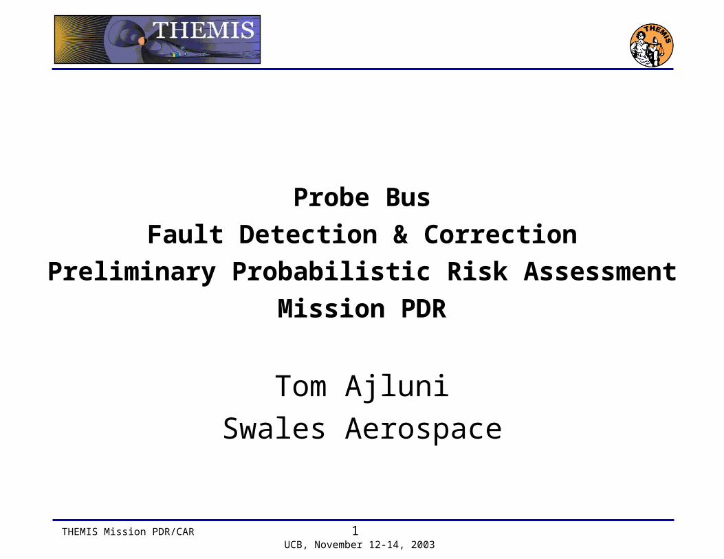
Bus Fault Detection and Correction Approach• Data Monitor function in flight Software (TSM)
– Out of limit triggers a call RTS’s
• Relative Time Sequence (RTS) is a high level script that performs autonomous actions when enabled
• Hardware Fault Detection– Power Card for voltage/current protection– Processor Card for watchdog timers
• Ground Monitoring– Real Time Monitoring of Critical Events– Contingency Procedures
• Operator Training– Simulations– Flatsat– Mission Sims using Flight Probes– Documentation and Operation Manuals
THEMIS Mission PDR/CAR 3 UCB, November 12-14, 2003
Example Data Monitoring

THEMIS Mission PDR/CAR 4 UCB, November 12-14, 2003
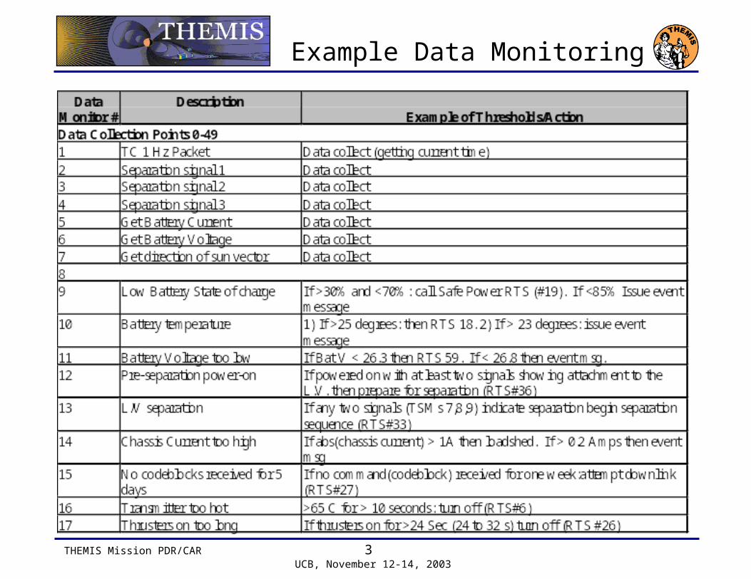
Example of RTS’s
RTS Title Calls RTS (which calls other RTSs..) TSM , (and by other TSMs through RTSs) RTS (which is called by…) FDC Recovery Procedure Contingency Plan/Tree
1 Safe Power parameters (50, 54, (55, 60)) 19 (18, 59)2 Close latch valve 26 (73) 68, 69, 70 RCS 7.1 Latch Valve Ops.3 Tx off 233 , ((76, (66, (50, 54, (55,60), 232)))) 13 (10(2(19(18, 59), 27))) rf_xbnd_rsn_on.prc4 Instruments emergency off 103 ali_pwron.prc ALI 10.2-85 Instruments to low power mode6 Loadshed 75, 13 (8,20(74),6,32), 14 (21,28),
15, 16, 1776 , (66, (50, 54, (55,60), 232)) 2 (19(18, 59), 27) C&DH 5.1 E
7 Reset PSE 216 RSN 12.18 Safe instruments 67 ALI 10.2-5,9 Thrusters off 73 234 , (68, 69, 70) 4 ACS RCS 7.1 Latch Valve Ops.10 Attempt downlink 2 (10(75, 13(8,20(74),6,32), 14(21,28),
15, 16, 17))232 C&DH 5.1 D, COMM 2.2
11 L/V separation 71, (63) 3612 Deployment 7313 Pre-separation power on 33 6314 Low Batt voltage 19 (3,2(10(75, 13(8,20(74),6,32),
14(21,28), 15, 16, 17)))60 C&DH 5.1 D
15 Turn Instrument deployment bus off 75, (72) 34
Called By
THEMIS Mission PDR/CAR 5 UCB, November 12-14, 2003
Probe Bus
Preliminary Probabilistic Risk Assessment
Mission PDRTom Ajluni
Swales Aerospace
THEMIS Mission PDR/CAR 6 UCB, November 12-14, 2003
Overview
Preliminary Probabilistic Risk Assessment (PRA)
for the Probe Bus• This PRA is “Semi”-Qualitative
– It is based upon an informal FMEA; formal Master Logic Diagram, Event Diagrams, and Fault Trees were deemed not practical for a pre-PDR single-string design.
– Numerical reliability estimates were adopted from the THEMIS Phase A Study (those values were taken from a reliability analysis performed for the very successful Swales EO-1 spacecraft).
– The EO-1 numbers were taken from industry data for similar spacecraft subsystems that have flown.
• Probe Bus Failure Consequence Severities– Postulated Probe Bus failures were binned into 5 levels of Severity
– “Level 5” – the most severe consequence – was reserved for Human Injury or Launch Vehicle Damage
– “Level 1” through “Level 4” represent bins for Probe functionality as a result of each postulated Probe Bus failure.

THEMIS Mission PDR/CAR 7 UCB, November 12-14, 2003
Risk Bins on the Matrix
Risk Matrix Event Color-Coding Represent Risk Bins
PROBE SUBSYSTEM PRA MATRIX RISK BINS
SEVERITY CATEGORY OF PROBE FAILURE
1
1
1
1
1
2
2
6
3
3
3
3
4
4
4
5
55 2
7
7
7
7
1 2 3 4 5NONE MINOR MAJOR TOTAL LOSS HUMAN
HARM OR LVDAMAGE
P(S)0.0000
0.9998
0.99970.9996
0.99920.9994
0.9999
0.9980
0.99700.9960
0.99200.9940
0.9990
0.9800
0.97000.9600
0.92000.9400
0.9900
0.8000
0.70000.6000
0.20000.4000
0.9000
P(F)1.0000
0.0002
0.00030.0004
0.00080.0006
0.0001
0.0020
0.00300.0040
0.00800.0060
0.0010
0.0200
0.03000.0400
0.08000.0600
0.0100
0.2000
0.30000.4000
0.80000.6000
0.1000
HUMAN orLV RISK
RISK RANKING,HIGHEST AT TOP
RISK RANKING,LOWEST AT
BOTTOM
HIGHESTPROBE
RISK
LOWESTPROBE
RISK

THEMIS Mission PDR/CAR 8 UCB, November 12-14, 2003
Risk Matrix Commentary, Page 2
Risk Matrix Commentary, Continued• Risk Items
– A bit arbitrarily noted over others, 5 failure events seem to stand out as primary Probe functional risks.
– The 2 “Orange” items (Severity Category 4) are distinct risks.– Communication Subsystem– C&DH/Processor Subsystem
– The 3 “Brown” items (Severity Categories 4 and 2) have failure probabilities a decade or more less.
– Electrical Power Subsystem (2 items)– Reaction Control Subsystem
• Investigation of These Risk Items– These failure events were back-tracked through the Failure
Analysis Spreadsheet to their major Component-level contributors. (This audit process is color-coded on the Spreadsheet backup data.)
– No surprises for the 2 “Orange” items!
THEMIS Mission PDR/CAR 9 UCB, November 12-14, 2003
Risk Matrix Commentary, Page 3
Investigation of Preliminary Risk Items• Communication Subsystem “Orange” Risk
– Severity Category 4: Transponder
• C&DH/Processor Subsystem “Orange” Risk– Severity Category 4: ColdFire® Processor and Bulk Memory
share equally
• Electrical Power Subsystem “Brown” Risk (2 Items)– Severity Category 4: Switched Shunt Control Circuitry– Severity Category 2: Each of the four Side Panel Solar
Arrays share equally
• Reaction Control Subsystem “Brown” Risk– Severity Category 4: Thruster Valves, 4 pairs share equally
THEMIS Mission PDR/CAR 10 UCB, November 12-14, 2003
Risk Matrix Commentary, Page 2
Risk Matrix Commentary, Continued• Risk Items
– A bit arbitrarily noted over others, 5 failure events seem to stand out as primary Probe functional risks.
– The 2 “Orange” items (Severity Category 4) are distinct risks.– Communication Subsystem– C&DH/Processor Subsystem
– The 3 “Brown” items (Severity Categories 4 and 2) have failure probabilities a decade or more less.
– Electrical Power Subsystem (2 items)– Reaction Control Subsystem
• Investigation of These Risk Items– These failure events were back-tracked through the Failure
Analysis Spreadsheet to their major Component-level contributors. (This audit process is color-coded on the Spreadsheet backup data.)
– No surprises for the 2 “Orange” items!

THEMIS Mission PDR/CAR 11 UCB, November 12-14, 2003
Risk Matrix Commentary, Page 3
Investigation of Preliminary Risk Items• Communication Subsystem “Orange” Risk
– Severity Category 4: Transponder
• C&DH/Processor Subsystem “Orange” Risk– Severity Category 4: ColdFire® Processor and Bulk Memory
share equally
• Electrical Power Subsystem “Brown” Risk (2 Items)– Severity Category 4: Switched Shunt Control Circuitry– Severity Category 2: Each of the four Side Panel Solar
Arrays share equally
• Reaction Control Subsystem “Brown” Risk– Severity Category 4: Thruster Valves, 4 pairs share equally

THEMIS Mission PDR/CAR 12 UCB, November 12-14, 2003
Spreadsheet Analysis, Page 1
Spreadsheet Analysis, Summary WorksheetTHEMIS RELIABILITY CALCULATIONS ROLL-UP FOR PRAINITIATING EVENT FAILURES("ROLL-UP" OF NUMERICAL CALCULATIONS USING THE "MINI" FMEA OUTLINE)
P(S) for P(S) for P(S) for P(S) for P(S) for P(S) for P(S) for P(S) for P(S) for P(S) forSev Cat 5 Sev Cat 4 Sev Cat 3 Sev Cat 2 Sev Cat 1 Sev Cat 5 Sev Cat 4 Sev Cat 3 Sev Cat 2 Sev Cat 1
1 ELECTRICAL POWER SUBSYSTEM 0.9998 0.9919 0.9962 0.9876 0.9996All 1.1 Solar Arrays 0.99131.2 Battery Explosion - Safety issue! 0.99981.2 Battery 0.99841.3 Battery Relay (BERB) 0.9996All 1.4 Shunt Regulation 0.9965 0.9965 0.9963All 1.5 Power Distribution 0.9974 0.9996 0.9996
2 ATTITUDE CONTROL SUBSYSTEM 0.9974 0.9991 0.99822.1 Sun Sensor 0.9991All 2.2 Solid State Gyros (Quan 2) 1.0000 0.99822.3 3-Axis Magnetometer (FGM Instrument) 0.99822.4 Software Functions 0.9991
3 REACTION CONTROL SUBSYSTEM 0.9931 0.9984 0.9992 0.99313.1 Software Functions 0.9991All 3.2 Tanks (Quan 2) 0.99913.3 Flight Pressure Transducer 0.99973.4 Thermistors 0.99973.5 PRTs 0.99973.6 Pressure/Vent Valve (Quan 1, Manual) 0.99993.7 Fill/Drain Valve (Quan 1 per Tank, Manual) 0.9999All 3.8 Filter (Quan 2) 0.9997 0.9995 0.9997All 3.9 Latch Valve (Quan 2) 0.9995 0.9989 0.99953.10 Orifice - No Credible Failure Mode3.11 Lines 0.9991All 3.12 Line Heater Series Strings 1.0000 0.9995All 3.13 Tank Heaters 1.0000 0.9995All 3.14 Thruster Heaters 1.0000 0.9979All 3.15 Thruster Valves 0.9965All 3.16 CatBed Heater 1.0000 0.9972
All 4. COMMUNICATION SUBSYSTEM 0.9073 0.9958 0.9986 0.9073 0.9958 0.9986
All 5. C&DH/PROCESSOR SUBSYSTEM 0.9588 0.9982 0.9974 0.9588 0.9982 0.9974
All 6. BACKPLANE 0.9974 0.9974
All 7. HARNESS AND GROUNDING 0.9993 1.0000 0.9996 0.9956 0.9993 1.0000 0.9996 0.9956
SUBSYSTEM P(S)'S GROUPED BY SEVERITY CATEGORY:
COMPONENT P(S)'S GROUPED BY SEVERITY CATEGORY:

THEMIS Mission PDR/CAR 13 UCB, November 12-14, 2003
Probe Bus Preliminary Probabilistic Risk Assessment
Mission PDR
Backup Charts & Data
THEMIS Mission PDR/CAR 14 UCB, November 12-14, 2003
PRA Background
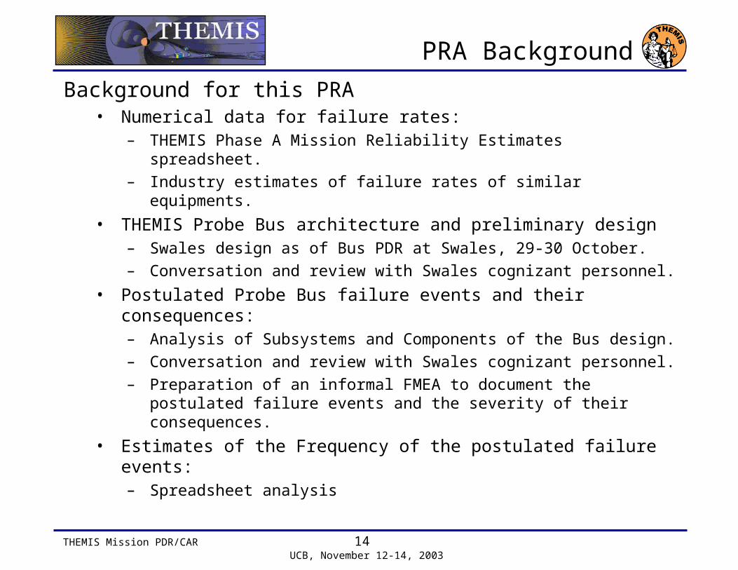
Background for this PRA• Numerical data for failure rates:
– THEMIS Phase A Mission Reliability Estimates spreadsheet.– Industry estimates of failure rates of similar equipments.
• THEMIS Probe Bus architecture and preliminary design– Swales design as of Bus PDR at Swales, 29-30 October.– Conversation and review with Swales cognizant personnel.
• Postulated Probe Bus failure events and their consequences:– Analysis of Subsystems and Components of the Bus design.– Conversation and review with Swales cognizant personnel.– Preparation of an informal FMEA to document the postulated
failure events and the severity of their consequences.
• Estimates of the Frequency of the postulated failure events:– Spreadsheet analysis

THEMIS Mission PDR/CAR 15 UCB, November 12-14, 2003
Procedure and Documentation,Page 1 of 2
The Following Procedure and Documentation Supports this PRA• Numerical data for failure rates:
– Informally extracted from Swales and Industry EO-1 data.– Data is available in the spreadsheet calculations performed
for this Preliminary PRA.
• THEMIS Probe Bus architecture and preliminary design– Swales design review documentation for the Bus PDR at
Swales, 29-30 October.
• Postulated Probe Bus failure events, their Results, and the Severity consequences:– Informal FMEA to document the postulated failure events and
the severity of their consequences.– This document also describes the Severity Categories.

THEMIS Mission PDR/CAR 16 UCB, November 12-14, 2003
Procedure and Documentation,Page 2 of 2
The Following Procedure and Documentation Supports this PRA - Concluded• Spreadsheet Analysis of the frequency of the postulated
failure events:– Spreadsheet analysis starts with the postulated failure events
and the failure rate numerical estimates. – Spreadsheet analysis combines the failure events and
estimated rates into Success and Failure Probabilities P(S) and P(F) for each resultant Probe Bus failure.
– The spreadsheet rolls up the Probabilities into Probe Components and Probe Subsystems.
– The Probe Component and Probe Subsystem Probabilities are binned into their assigned Consequence Severity bins.
• Graphical Presentation– A 5 x 4 color-coded matrix presents Failure Probabilities at
the Subsystem level as a function of their assigned Consequence Severity bins.
– Two failure events stand out and another three are notable.
THEMIS Mission PDR/CAR 17 UCB, November 12-14, 2003
Probe Failure Severity Categories
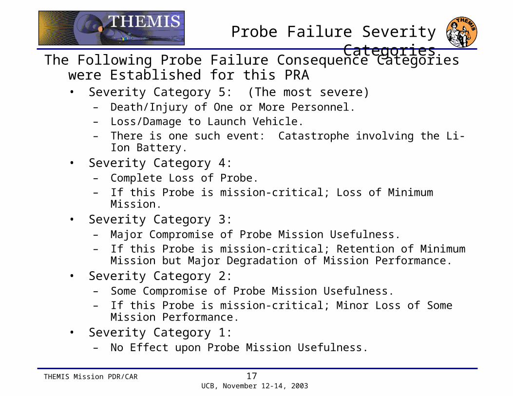
The Following Probe Failure Consequence Categories were Established for this PRA• Severity Category 5: (The most severe)
– Death/Injury of One or More Personnel.– Loss/Damage to Launch Vehicle.– There is one such event: Catastrophe involving the Li-Ion Battery.
• Severity Category 4:– Complete Loss of Probe.– If this Probe is mission-critical; Loss of Minimum Mission.
• Severity Category 3:– Major Compromise of Probe Mission Usefulness.– If this Probe is mission-critical; Retention of Minimum Mission but
Major Degradation of Mission Performance.
• Severity Category 2:– Some Compromise of Probe Mission Usefulness.– If this Probe is mission-critical; Minor Loss of Some Mission
Performance.
• Severity Category 1:– No Effect upon Probe Mission Usefulness.
THEMIS Mission PDR/CAR 18 UCB, November 12-14, 2003
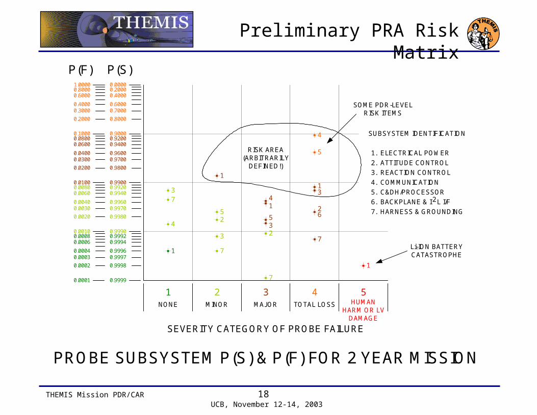
Preliminary PRA Risk Matrix
PROBE SUBSYSTEM P(S) & P(F) FOR 2 YEAR MISSION
1
1
1
1
1
2
2
6
3
3
3
3
4
4
4
5
55 2
7
7
7
7
1 2 3 4 5
SEVERITY CATEGORY OF PROBE FAILURE
NONE MINOR MAJOR TOTAL LOSS HUMANHARM OR LV
DAMAGE
P(S)0.0000
0.9998
0.99970.9996
0.99920.9994
0.9999
0.9980
0.99700.9960
0.99200.9940
0.9990
0.9800
0.97000.9600
0.92000.9400
0.9900
0.8000
0.70000.6000
0.20000.4000
0.9000
P(F)1.0000
0.0002
0.00030.0004
0.00080.0006
0.0001
0.0020
0.00300.0040
0.00800.0060
0.0010
0.0200
0.03000.0400
0.08000.0600
0.0100
0.2000
0.30000.4000
0.80000.6000
0.1000 SUBSYSTEM IDENTIFICATION
1. ELECTRICAL POWER
2. ATTITUDE CONTROL
3. REACTION CONTROL
4. COMMUNICATION
5. C&DH/PROCESSOR
7. HARNESS & GROUNDING
L I/F26. BACKPLANE & I
SOME PDR-LEVELRISK ITEMS
RISK AREA(ARBITRARILY
DEFINED!)
Li-ION BATTERYCATASTROPHE
THEMIS Mission PDR/CAR 19 UCB, November 12-14, 2003
Risk Matrix Commentary, Page 1
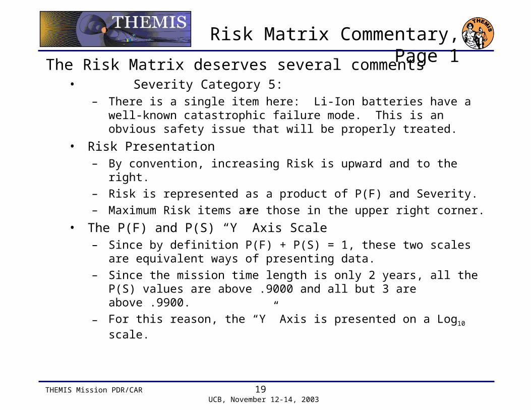
The Risk Matrix deserves several comments• Severity Category 5:
– There is a single item here: Li-Ion batteries have a well-known catastrophic failure mode. This is an obvious safety issue that will be properly treated.
• Risk Presentation– By convention, increasing Risk is upward and to the right.– Risk is represented as a product of P(F) and Severity.– Maximum Risk items are those in the upper right corner.
• The P(F) and P(S) “Y” Axis Scale– Since by definition P(F) + P(S) = 1, these two scales are
equivalent ways of presenting data.– Since the mission time length is only 2 years, all the P(S)
values are above .9000 and all but 3 are above .9900.
– For this reason, the “Y” Axis is presented on a Log10 scale.
THEMIS Mission PDR/CAR 20 UCB, November 12-14, 2003
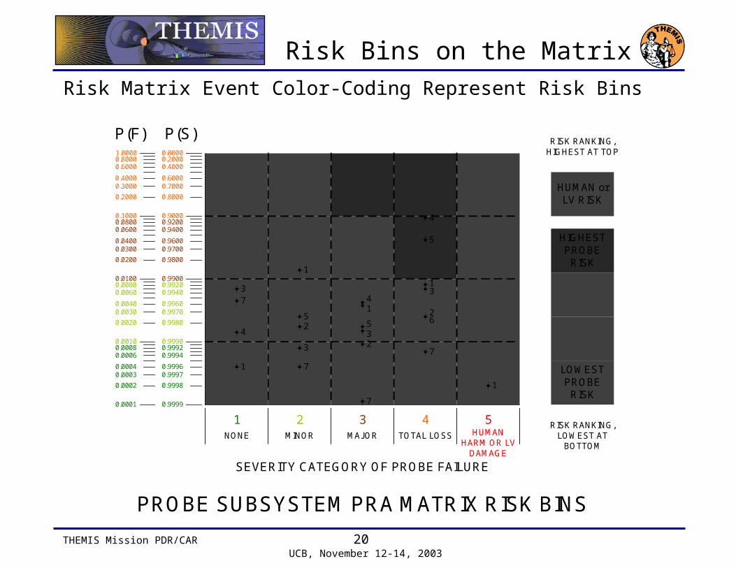
Risk Bins on the Matrix
Risk Matrix Event Color-Coding Represent Risk Bins
PROBE SUBSYSTEM PRA MATRIX RISK BINS
SEVERITY CATEGORY OF PROBE FAILURE
1
1
1
1
1
2
2
6
3
3
3
3
4
4
4
5
55 2
7
7
7
7
1 2 3 4 5NONE MINOR MAJOR TOTAL LOSS HUMAN
HARM OR LVDAMAGE
P(S)0.0000
0.9998
0.99970.9996
0.99920.9994
0.9999
0.9980
0.99700.9960
0.99200.9940
0.9990
0.9800
0.97000.9600
0.92000.9400
0.9900
0.8000
0.70000.6000
0.20000.4000
0.9000
P(F)1.0000
0.0002
0.00030.0004
0.00080.0006
0.0001
0.0020
0.00300.0040
0.00800.0060
0.0010
0.0200
0.03000.0400
0.08000.0600
0.0100
0.2000
0.30000.4000
0.80000.6000
0.1000
HUMAN orLV RISK
RISK RANKING,HIGHEST AT TOP
RISK RANKING,LOWEST AT
BOTTOM
HIGHESTPROBE
RISK
LOWESTPROBE
RISK
THEMIS Mission PDR/CAR 21 UCB, November 12-14, 2003
Risk Matrix Commentary, Page 2
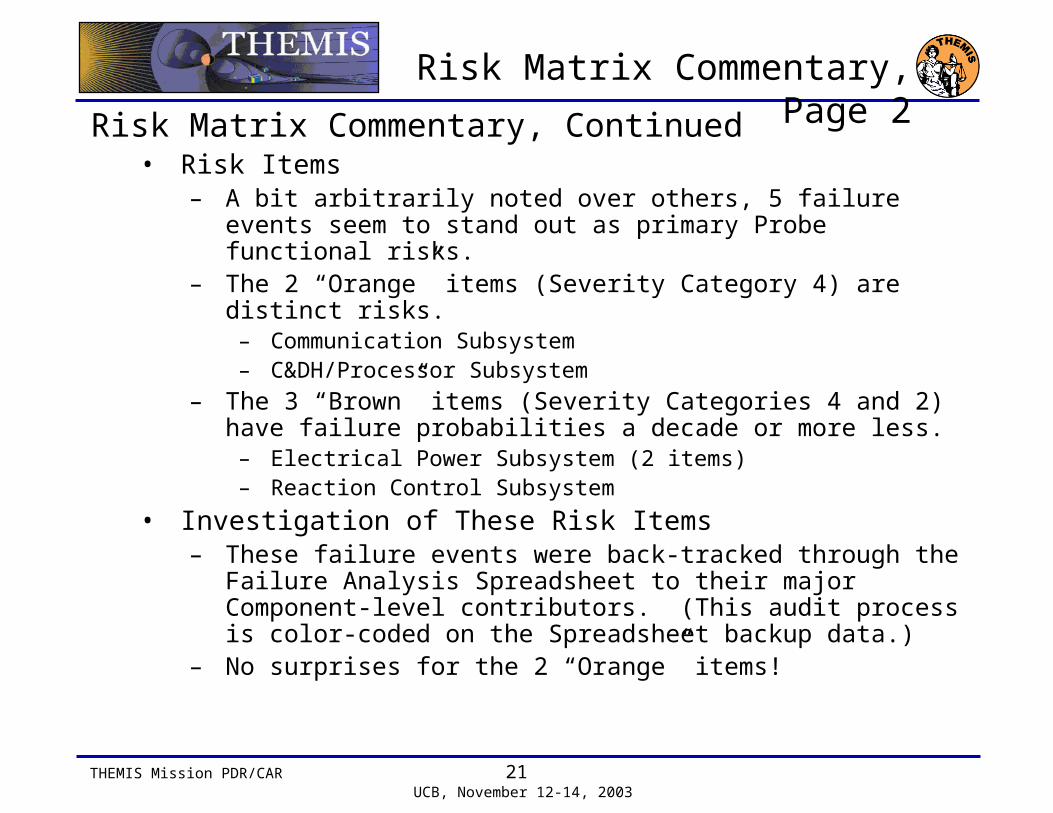
Risk Matrix Commentary, Continued• Risk Items
– A bit arbitrarily noted over others, 5 failure events seem to stand out as primary Probe functional risks.
– The 2 “Orange” items (Severity Category 4) are distinct risks.– Communication Subsystem– C&DH/Processor Subsystem
– The 3 “Brown” items (Severity Categories 4 and 2) have failure probabilities a decade or more less.
– Electrical Power Subsystem (2 items)– Reaction Control Subsystem
• Investigation of These Risk Items– These failure events were back-tracked through the Failure
Analysis Spreadsheet to their major Component-level contributors. (This audit process is color-coded on the Spreadsheet backup data.)
– No surprises for the 2 “Orange” items!

THEMIS Mission PDR/CAR 22 UCB, November 12-14, 2003
Risk Matrix Commentary, Page 3
Investigation of Preliminary Risk Items• Communication Subsystem “Orange” Risk
– Severity Category 4: Transponder
• C&DH/Processor Subsystem “Orange” Risk– Severity Category 4: ColdFire® Processor and Bulk Memory
share equally
• Electrical Power Subsystem “Brown” Risk (2 Items)– Severity Category 4: Switched Shunt Control Circuitry– Severity Category 2: Each of the four Side Panel Solar
Arrays share equally
• Reaction Control Subsystem “Brown” Risk– Severity Category 4: Thruster Valves, 4 pairs share equally
THEMIS Mission PDR/CAR 23 UCB, November 12-14, 2003
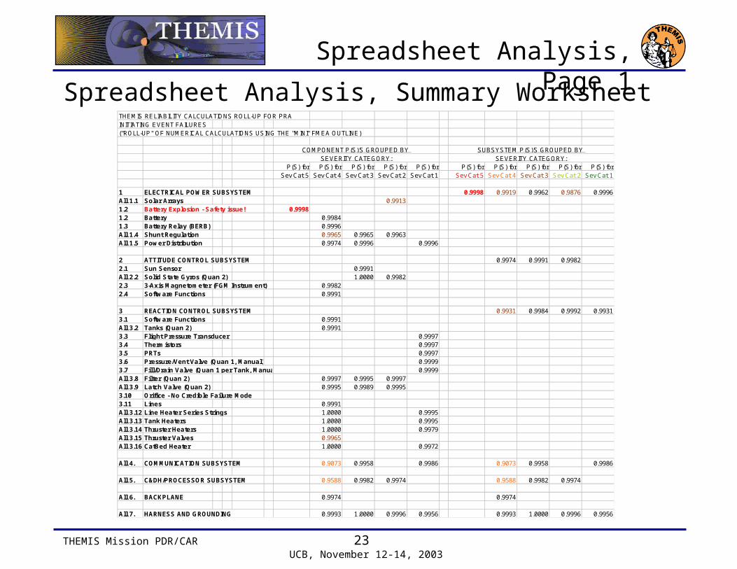
Spreadsheet Analysis, Page 1
Spreadsheet Analysis, Summary WorksheetTHEMIS RELIABILITY CALCULATIONS ROLL-UP FOR PRAINITIATING EVENT FAILURES("ROLL-UP" OF NUMERICAL CALCULATIONS USING THE "MINI" FMEA OUTLINE)
P(S) for P(S) for P(S) for P(S) for P(S) for P(S) for P(S) for P(S) for P(S) for P(S) forSev Cat 5 Sev Cat 4 Sev Cat 3 Sev Cat 2 Sev Cat 1 Sev Cat 5 Sev Cat 4 Sev Cat 3 Sev Cat 2 Sev Cat 1
1 ELECTRICAL POWER SUBSYSTEM 0.9998 0.9919 0.9962 0.9876 0.9996All 1.1 Solar Arrays 0.99131.2 Battery Explosion - Safety issue! 0.99981.2 Battery 0.99841.3 Battery Relay (BERB) 0.9996All 1.4 Shunt Regulation 0.9965 0.9965 0.9963All 1.5 Power Distribution 0.9974 0.9996 0.9996
2 ATTITUDE CONTROL SUBSYSTEM 0.9974 0.9991 0.99822.1 Sun Sensor 0.9991All 2.2 Solid State Gyros (Quan 2) 1.0000 0.99822.3 3-Axis Magnetometer (FGM Instrument) 0.99822.4 Software Functions 0.9991
3 REACTION CONTROL SUBSYSTEM 0.9931 0.9984 0.9992 0.99313.1 Software Functions 0.9991All 3.2 Tanks (Quan 2) 0.99913.3 Flight Pressure Transducer 0.99973.4 Thermistors 0.99973.5 PRTs 0.99973.6 Pressure/Vent Valve (Quan 1, Manual) 0.99993.7 Fill/Drain Valve (Quan 1 per Tank, Manual) 0.9999All 3.8 Filter (Quan 2) 0.9997 0.9995 0.9997All 3.9 Latch Valve (Quan 2) 0.9995 0.9989 0.99953.10 Orifice - No Credible Failure Mode3.11 Lines 0.9991All 3.12 Line Heater Series Strings 1.0000 0.9995All 3.13 Tank Heaters 1.0000 0.9995All 3.14 Thruster Heaters 1.0000 0.9979All 3.15 Thruster Valves 0.9965All 3.16 CatBed Heater 1.0000 0.9972
All 4. COMMUNICATION SUBSYSTEM 0.9073 0.9958 0.9986 0.9073 0.9958 0.9986
All 5. C&DH/PROCESSOR SUBSYSTEM 0.9588 0.9982 0.9974 0.9588 0.9982 0.9974
All 6. BACKPLANE 0.9974 0.9974
All 7. HARNESS AND GROUNDING 0.9993 1.0000 0.9996 0.9956 0.9993 1.0000 0.9996 0.9956
SUBSYSTEM P(S)'S GROUPED BY SEVERITY CATEGORY:
COMPONENT P(S)'S GROUPED BY SEVERITY CATEGORY:
THEMIS Mission PDR/CAR 24 UCB, November 12-14, 2003
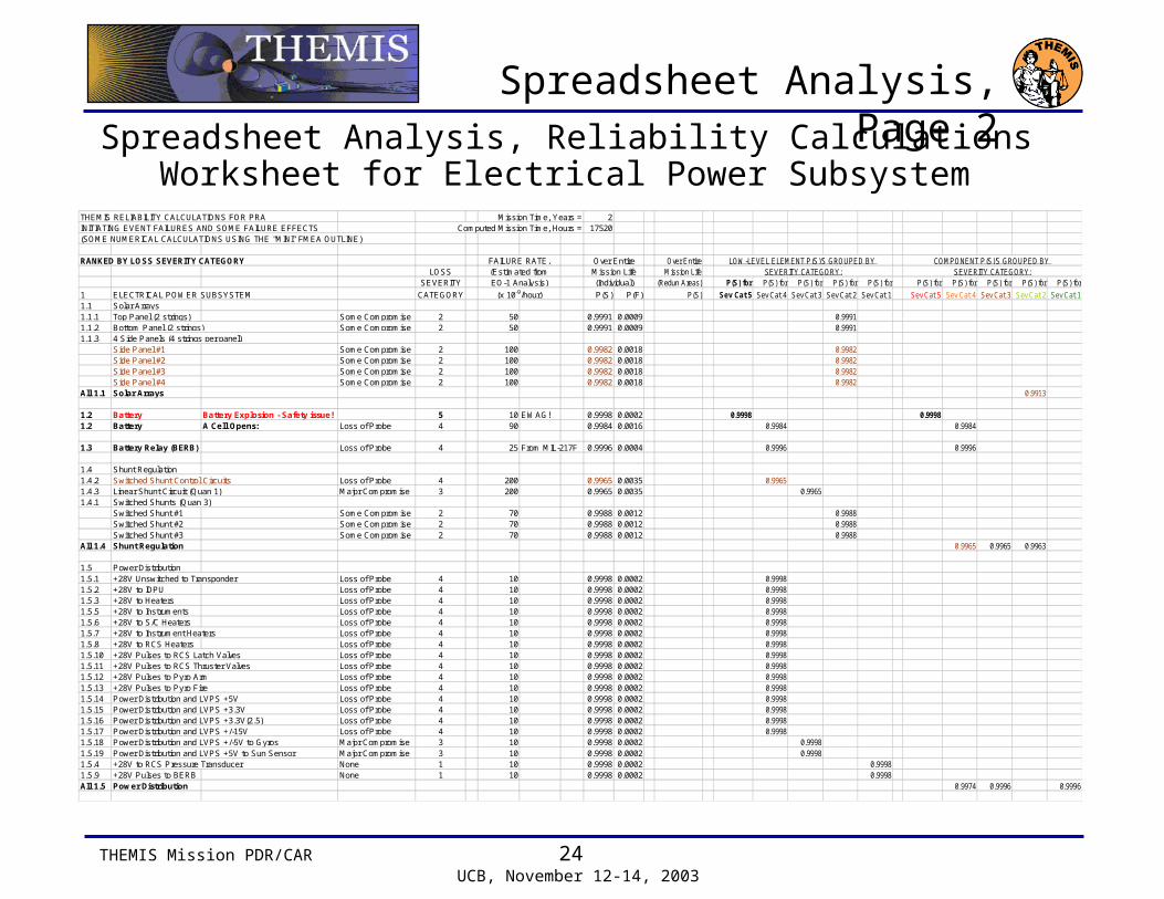
Spreadsheet Analysis, Page 2Spreadsheet Analysis, Reliability Calculations Worksheet for
Electrical Power SubsystemTHEMIS RELIABILITY CALCULATIONS FOR PRA Mission Time, Years = 2INITIATING EVENT FAILURES AND SOME FAILURE EFFECTS Computed Mission Time, Hours = 17520(SOME NUMERICAL CALCULATIONS USING THE "MINI" FMEA OUTLINE)
RANKED BY LOSS SEVERITY CATEGORYLOSS
SEVERITY
1 ELECTRICAL POWER SUBSYSTEM CATEGORY P(S) P(F)1.1 Solar Arrays1.1.1 Top Panel (2 strings) Some Compromise 2 50 0.9991 0.00091.1.2 Bottom Panel (2 strings) Some Compromise 2 50 0.9991 0.00091.1.3 4 Side Panels (4 strings per panel)
Side Panel #1 Some Compromise 2 100 0.9982 0.0018Side Panel #2 Some Compromise 2 100 0.9982 0.0018Side Panel #3 Some Compromise 2 100 0.9982 0.0018Side Panel #4 Some Compromise 2 100 0.9982 0.0018
All 1.1 Solar Arrays
1.2 Battery Battery Explosion - Safety issue! 5 10 EWAG! 0.9998 0.00021.2 Battery A Cell Opens: Loss of Probe 4 90 0.9984 0.0016
1.3 Battery Relay (BERB) Loss of Probe 4 25 From MIL-217F 0.9996 0.0004
1.4 Shunt Regulation1.4.2 Switched Shunt Control Circuits Loss of Probe 4 200 0.9965 0.00351.4.3 Linear Shunt Circuit (Quan 1) Major Compromise 3 200 0.9965 0.00351.4.1 Switched Shunts (Quan 3)
Switched Shunt #1 Some Compromise 2 70 0.9988 0.0012Switched Shunt #2 Some Compromise 2 70 0.9988 0.0012Switched Shunt #3 Some Compromise 2 70 0.9988 0.0012
All 1.4 Shunt Regulation
1.5 Power Distribution1.5.1 +28V Unswitched to Transponder Loss of Probe 4 10 0.9998 0.00021.5.2 +28V to IDPU Loss of Probe 4 10 0.9998 0.00021.5.3 +28V to Heaters Loss of Probe 4 10 0.9998 0.00021.5.5 +28V to Instruments Loss of Probe 4 10 0.9998 0.00021.5.6 +28V to S/C Heaters Loss of Probe 4 10 0.9998 0.00021.5.7 +28V to Instrument Heaters Loss of Probe 4 10 0.9998 0.00021.5.8 +28V to RCS Heaters Loss of Probe 4 10 0.9998 0.00021.5.10 +28V Pulses to RCS Latch Valves Loss of Probe 4 10 0.9998 0.00021.5.11 +28V Pulses to RCS Thruster Valves Loss of Probe 4 10 0.9998 0.00021.5.12 +28V Pulses to Pyro Arm Loss of Probe 4 10 0.9998 0.00021.5.13 +28V Pulses to Pyro Fire Loss of Probe 4 10 0.9998 0.00021.5.14 Power Distribution and LVPS +5V Loss of Probe 4 10 0.9998 0.00021.5.15 Power Distribution and LVPS +3.3V Loss of Probe 4 10 0.9998 0.00021.5.16 Power Distribution and LVPS +3.3V(2.5) Loss of Probe 4 10 0.9998 0.00021.5.17 Power Distribution and LVPS +/-15V Loss of Probe 4 10 0.9998 0.00021.5.18 Power Distribution and LVPS +/-5V to Gyros Major Compromise 3 10 0.9998 0.00021.5.19 Power Distribution and LVPS +5V to Sun Sensor Major Compromise 3 10 0.9998 0.00021.5.4 +28V to RCS Pressure Transducer None 1 10 0.9998 0.00021.5.9 +28V Pulses to BERB None 1 10 0.9998 0.0002All 1.5 Power Distribution
(x 10-9/hour)
Over Entire
(Individual)Mission Life
FAILURE RATE,(Estimated fromEO-1 Analysis)
Over EntireMission Life
(Redun Areas) P(S) for P(S) for P(S) for P(S) for P(S) for P(S) for P(S) for P(S) for P(S) for P(S) for
P(S) Sev Cat 5 Sev Cat 4 Sev Cat 3 Sev Cat 2 Sev Cat 1 Sev Cat 5 Sev Cat 4 Sev Cat 3 Sev Cat 2 Sev Cat 1
0.99910.9991
0.99820.99820.99820.9982
0.9913
0.9998 0.99980.9984 0.9984
0.9996 0.9996
0.99650.9965
0.99880.99880.9988
0.9965 0.9965 0.9963
0.99980.99980.99980.99980.99980.99980.99980.99980.99980.99980.99980.99980.99980.99980.9998
0.99980.9998
0.99980.9998
0.9974 0.9996 0.9996
COMPONENT P(S)'S GROUPED BY SEVERITY CATEGORY:
LOW-LEVEL ELEMENT P(S)'S GROUPED BY SEVERITY CATEGORY:
THEMIS Mission PDR/CAR 25 UCB, November 12-14, 2003
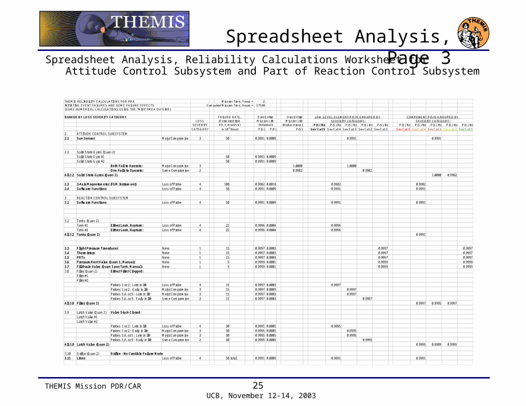
Spreadsheet Analysis, Page 3Spreadsheet Analysis, Reliability Calculations Worksheet for Attitude
Control Subsystem and Part of Reaction Control Subsystem
THEMIS RELIABILITY CALCULATIONS FOR PRA Mission Time, Years = 2INITIATING EVENT FAILURES AND SOME FAILURE EFFECTS Computed Mission Time, Hours = 17520(SOME NUMERICAL CALCULATIONS USING THE "MINI" FMEA OUTLINE)
RANKED BY LOSS SEVERITY CATEGORY Over EntireLOSS Mission Life
SEVERITY (Redun Areas)
CATEGORY P(S) P(F) P(S)(x 10-9/hour)
Over Entire
(Individual)Mission Life
FAILURE RATE,(Estimated fromEO-1 Analysis) P(S) for P(S) for P(S) for P(S) for P(S) for P(S) for P(S) for P(S) for P(S) for P(S) for
Sev Cat 5 Sev Cat 4 Sev Cat 3 Sev Cat 2 Sev Cat 1 Sev Cat 5 Sev Cat 4 Sev Cat 3 Sev Cat 2 Sev Cat 1
COMPONENT P(S)'S GROUPED BY SEVERITY CATEGORY:
LOW-LEVEL ELEMENT P(S)'S GROUPED BY SEVERITY CATEGORY:
2 ATTITUDE CONTROL SUBSYSTEM2.1 Sun Sensor Major Compromise 3 50 0.9991 0.0009
2.2 Solid State Gyros (Quan 2)Solid State Gyro #1 50 0.9991 0.0009Solid State Gyro #2 50 0.9991 0.0009
Both Fail to Operate: Major Compromise 3 1.0000One Fails to Operate: Some Compromise 2 0.9982
All 2.2 Solid State Gyros (Quan 2)
2.3 3-Axis Magnetometer (FGM Instrument) Loss of Probe 4 100 0.9982 0.00182.4 Software Functions Loss of Probe 4 50 0.9991 0.0009
3 REACTION CONTROL SUBSYSTEM3.1 Software Functions Loss of Probe 4 50 0.9991 0.0009
3.2 Tanks (Quan 2)Tank #1 Either Leak, Rupture: Loss of Probe 4 25 0.9996 0.0004Tank #2 Either Leak, Rupture: Loss of Probe 4 25 0.9996 0.0004
All 3.2 Tanks (Quan 2)
3.3 Flight Pressure Transducer None 1 15 0.9997 0.00033.4 Thermistors None 1 15 0.9997 0.00033.5 PRTs None 1 15 0.9997 0.00033.6 Pressure/Vent Valve (Quan 1, Manual) None 1 5 0.9999 0.00013.7 Fill/Drain Valve (Quan 1 per Tank, Manual) None 1 5 0.9999 0.00013.8 Filter (Quan 2) Either Filter Clogged:
Filter #1Filter #2
Probes 1 or 2: Late in life Loss of Probe 4 15 0.9997 0.0003Probes 1 or 2: Early in life Major Compromise 3 15 0.9997 0.0003Probes 3,4, or 5: Late in life Major Compromise 3 15 0.9997 0.0003Probes 3,4, or 5: Early in life Some Compromise 2 15 0.9997 0.0003
All 3.8 Filter (Quan 2)
3.9 Latch Valve (Quan 2) Valve Stuck Closed:Latch Valve #1Latch Valve #2
Probes 1 or 2: Late in life Loss of Probe 4 30 0.9995 0.0005Probes 1 or 2: Early in life Major Compromise 3 30 0.9995 0.0005Probes 3,4, or 5: Late in life Major Compromise 3 30 0.9995 0.0005Probes 3,4, or 5: Early in life Some Compromise 2 30 0.9995 0.0005
All 3.9 Latch Valve (Quan 2)
3.10 Orifice (Quan 2) Orifice - No Credible Failure Mode3.11 Lines Loss of Probe 4 50 total 0.9991 0.0009
0.9991 0.9991
1.00000.9982
1.0000 0.9982
0.9982 0.99820.9991 0.9991
0.9991 0.9991
0.99960.9996
0.9991
0.9997 0.99970.9997 0.99970.9997 0.99970.9999 0.99990.9999 0.9999
0.99970.99970.9997
0.99970.9997 0.9995 0.9997
0.99950.99950.9995
0.99950.9995 0.9989 0.9995
0.9991 0.9991
THEMIS Mission PDR/CAR 26 UCB, November 12-14, 2003
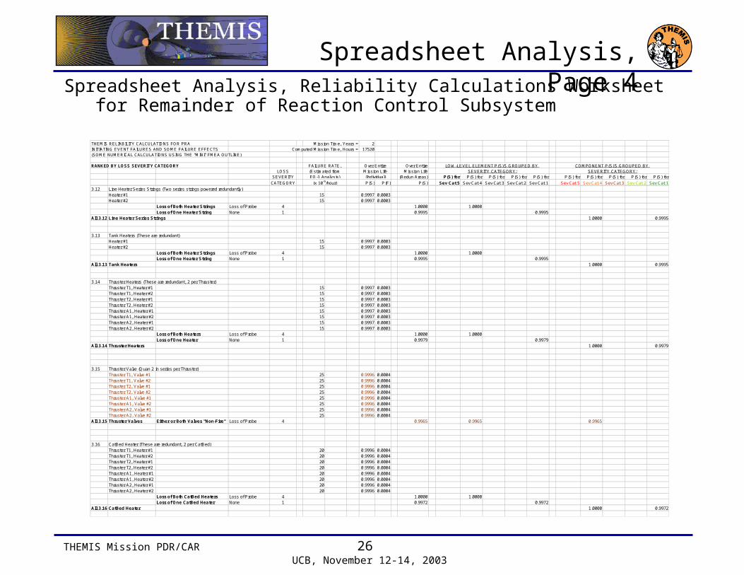
Spreadsheet Analysis, Page 4Spreadsheet Analysis, Reliability Calculations Worksheet for
Remainder of Reaction Control Subsystem
3.12 Line Heater Series Strings (Two series strings powered redundantly)Heater #1 15 0.9997 0.0003Heater #2 15 0.9997 0.0003
Loss of Both Heater Strings Loss of Probe 4 1.0000Loss of One Heater String None 1 0.9995
All 3.12 Line Heater Series Strings
3.13 Tank Heaters (These are redundant)Heater #1 15 0.9997 0.0003Heater #2 15 0.9997 0.0003
Loss of Both Heater Strings Loss of Probe 4 1.0000Loss of One Heater String None 1 0.9995
All 3.13 Tank Heaters
3.14 Thruster Heaters (These are redundant, 2 per Thruster)Thruster T1, Heater #1 15 0.9997 0.0003Thruster T1, Heater #2 15 0.9997 0.0003Thruster T2, Heater #1 15 0.9997 0.0003Thruster T2, Heater #2 15 0.9997 0.0003Thruster A1, Heater #1 15 0.9997 0.0003Thruster A1, Heater #2 15 0.9997 0.0003Thruster A2, Heater #1 15 0.9997 0.0003Thruster A2, Heater #2 15 0.9997 0.0003
Loss of Both Heaters Loss of Probe 4 1.0000Loss of One Heater None 1 0.9979
All 3.14 Thruster Heaters
3.15 Thruster Valve (Quan 2 in series per Thruster)Thruster T1, Valve #1 25 0.9996 0.0004Thruster T1, Valve #2 25 0.9996 0.0004Thruster T2, Valve #1 25 0.9996 0.0004Thruster T2, Valve #2 25 0.9996 0.0004Thruster A1, Valve #1 25 0.9996 0.0004Thruster A1, Valve #2 25 0.9996 0.0004Thruster A2, Valve #1 25 0.9996 0.0004Thruster A2, Valve #2 25 0.9996 0.0004
All 3.15 Thruster Valves Either or Both Valves "Non-Fire" Loss of Probe 4 0.9965
3.16 CatBed Heater (These are redundant, 2 per CatBed)Thruster T1, Heater #1 20 0.9996 0.0004Thruster T1, Heater #2 20 0.9996 0.0004Thruster T2, Heater #1 20 0.9996 0.0004Thruster T2, Heater #2 20 0.9996 0.0004Thruster A1, Heater #1 20 0.9996 0.0004Thruster A1, Heater #2 20 0.9996 0.0004Thruster A2, Heater #1 20 0.9996 0.0004Thruster A2, Heater #2 20 0.9996 0.0004
Loss of Both CatBed Heaters Loss of Probe 4 1.0000Loss of One CatBed Heater None 1 0.9972
All 3.16 CatBed Heater
THEMIS RELIABILITY CALCULATIONS FOR PRA Mission Time, Years = 2INITIATING EVENT FAILURES AND SOME FAILURE EFFECTS Computed Mission Time, Hours = 17520(SOME NUMERICAL CALCULATIONS USING THE "MINI" FMEA OUTLINE)
RANKED BY LOSS SEVERITY CATEGORY Over EntireLOSS Mission Life
SEVERITY (Redun Areas)
CATEGORY P(S) P(F) P(S)(x 10-9/hour)
Over Entire
(Individual)Mission Life
FAILURE RATE,(Estimated fromEO-1 Analysis) P(S) for P(S) for P(S) for P(S) for P(S) for P(S) for P(S) for P(S) for P(S) for P(S) for
Sev Cat 5 Sev Cat 4 Sev Cat 3 Sev Cat 2 Sev Cat 1 Sev Cat 5 Sev Cat 4 Sev Cat 3 Sev Cat 2 Sev Cat 1
COMPONENT P(S)'S GROUPED BY SEVERITY CATEGORY:
LOW-LEVEL ELEMENT P(S)'S GROUPED BY SEVERITY CATEGORY:
1.00000.9995
1.0000 0.9995
1.00000.9995
1.0000 0.9995
1.00000.9979
1.0000 0.9979
0.9965 0.9965
1.00000.9972
1.0000 0.9972

THEMIS Mission PDR/CAR 27 UCB, November 12-14, 2003
Spreadsheet Analysis, Page 5Spreadsheet Analysis, Reliability Calculations Worksheet for
Communication Subsystem and C&DH/Processor Subsystem
THEMIS RELIABILITY CALCULATIONS FOR PRA Mission Time, Years = 2INITIATING EVENT FAILURES AND SOME FAILURE EFFECTS Computed Mission Time, Hours = 17520(SOME NUMERICAL CALCULATIONS USING THE "MINI" FMEA OUTLINE)
RANKED BY LOSS SEVERITY CATEGORY Over EntireLOSS Mission Life
SEVERITY (Redun Areas)
CATEGORY P(S) P(F) P(S)(x 10-9/hour)
Over Entire
(Individual)Mission Life
FAILURE RATE,(Estimated fromEO-1 Analysis) P(S) for P(S) for P(S) for P(S) for P(S) for P(S) for P(S) for P(S) for P(S) for P(S) for
Sev Cat 5 Sev Cat 4 Sev Cat 3 Sev Cat 2 Sev Cat 1 Sev Cat 5 Sev Cat 4 Sev Cat 3 Sev Cat 2 Sev Cat 1
COMPONENT P(S)'S GROUPED BY SEVERITY CATEGORY:
LOW-LEVEL ELEMENT P(S)'S GROUPED BY SEVERITY CATEGORY:
4 COMMUNICATION SUBSYSTEM4.1 Antenna Loss of Probe 4 20 0.9996 0.00044.2 Transponder Loss of Probe 4 5000 0.9161 0.08394.3 Uplink FPGA on Communications Board Loss of Probe 4 80 0.9986 0.00144.4 Command FIFO (One Integrated Circuit Device) Loss of Probe 4 80 0.9986 0.00144.5 Discrete Cmd Gen (Part of Power Board FPGA) Loss of Probe 4 80 0.9986 0.00144.10 Telemetry FIFO (One Integrated Circuit Device) Loss of Probe 4 80 0.9986 0.00144.11 RS Encoder (One Integrated Circuit Device) Loss of Probe 4 80 0.9986 0.00144.12 Downlink FPGA on Communications Board Loss of Probe 4 80 0.9986 0.00144.13 Software Functions Loss of Probe 4 50 0.9991 0.00094.7 Analog Telemetry Current Source Major Compromise 3 80 0.9986 0.00144.8 Analog Telemetry Multiplexer Major Compromise 3 80 0.9986 0.00144.9 Telemetry Processor (Part of Power Board FPGA) Major Compromise 3 80 0.9986 0.00144.6 Separation Interface (Telemetry function only) None 1 80 0.9986 0.0014All 4. COMMUNICATION SUBSYSTEM
5 C&DH/PROCESSOR SUBSYSTEM5.1 Clock Oscillator Loss of Probe 4 100 0.9982 0.00185.2 ColdFire Processor Loss of Probe 4 600 0.9895 0.01055.3 Processor FPGA Loss of Probe 4 300 0.9948 0.00525.4 RAM Loss of Probe 4 100 0.9982 0.00185.5 Boot PROM Loss of Probe 4 50 0.9991 0.00095.6 Program Storage EEPROM Loss of Probe 4 100 0.9982 0.00185.7 RS-422 Command Driver to IDPU Loss of Probe 4 50 0.9991 0.00095.9 RS-422 2Mbps Data Receiver from IDPU Loss of Probe 4 50 0.9991 0.00095.10 RS-422 Clock Interfaces to IDPU Loss of Probe 4 50 0.9991 0.00095.14 Bulk Memory Loss of Probe 4 600 0.9895 0.01055.15 Bulk Memory FPGA Loss of Probe 4 300 0.9948 0.00525.16 Software Functions Loss of Probe 4 100 0.9982 0.00185.11 RS-422 One PPS Interfaces to IDPU Major Compromise 3 50 0.9991 0.00095.12 Sun Pulse Interface to IDPU Major Compromise 3 50 0.9991 0.00095.8 RS-422 Status Receiver from IDPU Some Compromise 2 50 0.9991 0.00095.13 3.3V Power Switch to EEPROMs Some Compromise 2 100 0.9982 0.0018All 5. C&DH/PROCESSOR SUBSYSTEM
0.99960.91610.99860.99860.99860.99860.99860.99860.9991
0.99860.99860.9986
0.99860.9073 0.9958 0.9986
0.99820.98950.99480.99820.99910.99820.99910.99910.99910.98950.99480.9982
0.99910.9991
0.99910.9982
0.9588 0.9982 0.9974
THEMIS Mission PDR/CAR 28 UCB, November 12-14, 2003
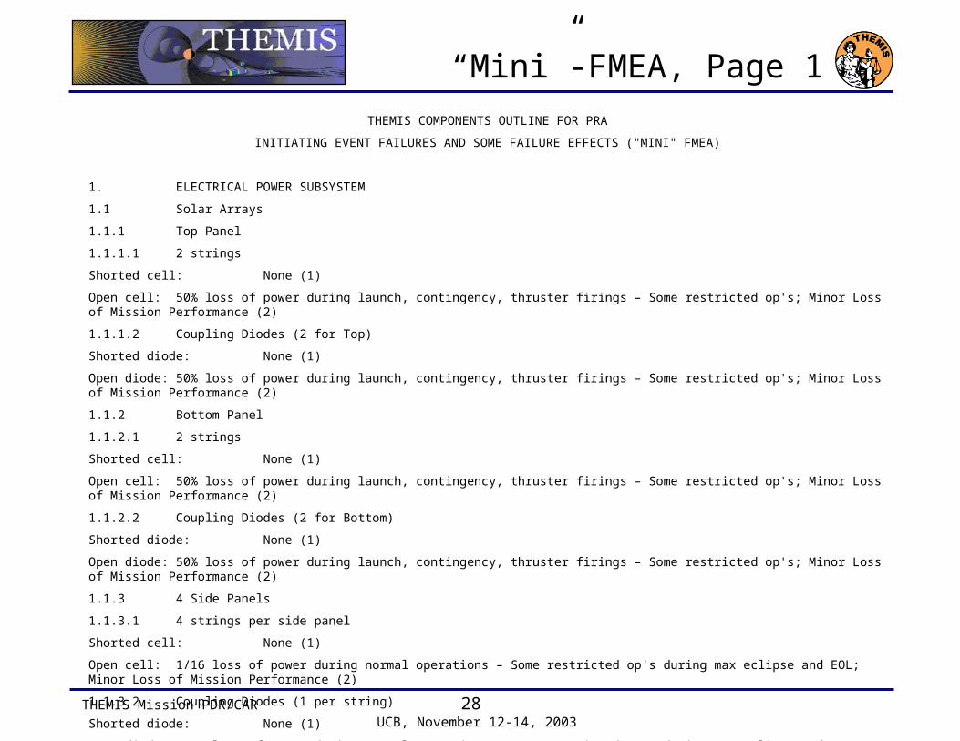
“Mini”-FMEA, Page 1
THEMIS COMPONENTS OUTLINE FOR PRA
INITIATING EVENT FAILURES AND SOME FAILURE EFFECTS ("MINI" FMEA)
1. ELECTRICAL POWER SUBSYSTEM
1.1 Solar Arrays
1.1.1 Top Panel
1.1.1.1 2 strings
Shorted cell: None (1)
Open cell: 50% loss of power during launch, contingency, thruster firings – Some restricted op's; Minor Loss of Mission Performance (2)
1.1.1.2 Coupling Diodes (2 for Top)
Shorted diode: None (1)
Open diode: 50% loss of power during launch, contingency, thruster firings – Some restricted op's; Minor Loss of Mission Performance (2)
1.1.2 Bottom Panel
1.1.2.1 2 strings
Shorted cell: None (1)
Open cell: 50% loss of power during launch, contingency, thruster firings – Some restricted op's; Minor Loss of Mission Performance (2)
1.1.2.2 Coupling Diodes (2 for Bottom)
Shorted diode: None (1)
Open diode: 50% loss of power during launch, contingency, thruster firings – Some restricted op's; Minor Loss of Mission Performance (2)
1.1.3 4 Side Panels
1.1.3.1 4 strings per side panel
Shorted cell: None (1)
Open cell: 1/16 loss of power during normal operations – Some restricted op's during max eclipse and EOL; Minor Loss of Mission Performance (2)
1.1.3.2 Coupling Diodes (1 per string)
Shorted diode: None (1)
Open diode: 1/16 loss of power during normal operations – Some restricted op's during max eclipse and EOL; Minor Loss of Mission Performance (2)

THEMIS Mission PDR/CAR 29 UCB, November 12-14, 2003
“Mini”-FMEA, Page 2
1.2 Battery
Battery Catastrophe – Explodes, etc.: Li-Ion batteries are dangerous – personnel or LV damage is possible – Cat (5). This is a safety issue!
Single Cell Shorts: Bus voltage a bit low; slight risk to operating battery to higher Depth of Discharge – None (1)
A Cell Opens: No battery, not a problem until eclipse – Loss of Probe (4)
1.3 Battery Relay (BERB)
"One shot" operation, set to "Battery ON-Line" before launch. Relay resets to "Battery OFF-Line" during mission:
No battery, not a problem until eclipse – Loss of Probe (4)
1.4 Shunt Regulation
1.4.1 Switched Shunts (Quan 3)
1.4.1.1 Shunt Transistor (1 per shunt)
Open: None (1)
Short: 25% loss of power during normal op's – Restricted op's during eclipse and EOL; Minor Loss of Mission Performance (2)
1.4.1.2 Coupling Diode (1 per shunt)
Short: None (1)
Open: 25% loss of power during normal op's – Restricted op's during eclipse and EOL; Minor Loss of Mission Performance (2)
1.4.1.3 Control Circuits
Circuit failure: Probable loss of power – Loss of Probe (4)
1.4.2 Linear Shunt Circuit (Quan 1), All components
Any failure: Loss of fine voltage regulation, bus voltage ripple excessive, possible degradation of science – Major Compromise of Probe Mission Usefulness (3)
THEMIS Mission PDR/CAR 30 UCB, November 12-14, 2003
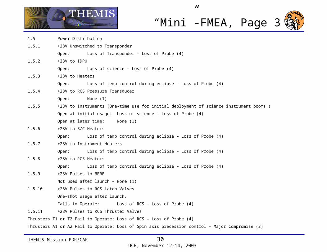
“Mini”-FMEA, Page 31.5 Power Distribution
1.5.1 +28V Unswitched to Transponder
Open: Loss of Transponder – Loss of Probe (4)
1.5.2 +28V to IDPU
Open: Loss of science – Loss of Probe (4)
1.5.3 +28V to Heaters
Open: Loss of temp control during eclipse – Loss of Probe (4)
1.5.4 +28V to RCS Pressure Transducer
Open: None (1)
1.5.5 +28V to Instruments (One-time use for initial deployment of science instrument booms.)
Open at initial usage: Loss of science – Loss of Probe (4)
Open at later time: None (1)
1.5.6 +28V to S/C Heaters
Open: Loss of temp control during eclipse – Loss of Probe (4)
1.5.7 +28V to Instrument Heaters
Open: Loss of temp control during eclipse – Loss of Probe (4)
1.5.8 +28V to RCS Heaters
Open: Loss of temp control during eclipse – Loss of Probe (4)
1.5.9 +28V Pulses to BERB
Not used after launch – None (1)
1.5.10 +28V Pulses to RCS Latch Valves
One–shot usage after launch.
Fails to Operate: Loss of RCS – Loss of Probe (4)
1.5.11 +28V Pulses to RCS Thruster Valves
Thrusters T1 or T2 Fail to Operate: Loss of RCS – Loss of Probe (4)
Thrusters A1 or A2 Fail to Operate:Loss of Spin axis precession control – Major Compromise (3)
THEMIS Mission PDR/CAR 31 UCB, November 12-14, 2003
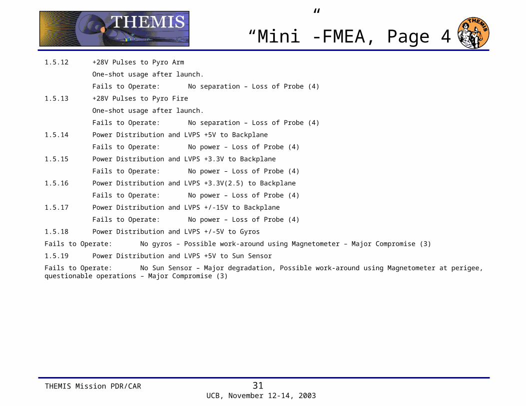
“Mini”-FMEA, Page 41.5.12 +28V Pulses to Pyro Arm
One–shot usage after launch.
Fails to Operate: No separation – Loss of Probe (4)
1.5.13 +28V Pulses to Pyro Fire
One–shot usage after launch.
Fails to Operate: No separation – Loss of Probe (4)
1.5.14 Power Distribution and LVPS +5V to Backplane
Fails to Operate: No power – Loss of Probe (4)
1.5.15 Power Distribution and LVPS +3.3V to Backplane
Fails to Operate: No power – Loss of Probe (4)
1.5.16 Power Distribution and LVPS +3.3V(2.5) to Backplane
Fails to Operate: No power – Loss of Probe (4)
1.5.17 Power Distribution and LVPS +/-15V to Backplane
Fails to Operate: No power – Loss of Probe (4)
1.5.18 Power Distribution and LVPS +/-5V to Gyros
Fails to Operate: No gyros – Possible work-around using Magnetometer – Major Compromise (3)
1.5.19 Power Distribution and LVPS +5V to Sun Sensor
Fails to Operate: No Sun Sensor – Major degradation, Possible work-around using Magnetometer at perigee, questionable operations – Major Compromise (3)
THEMIS Mission PDR/CAR 32 UCB, November 12-14, 2003
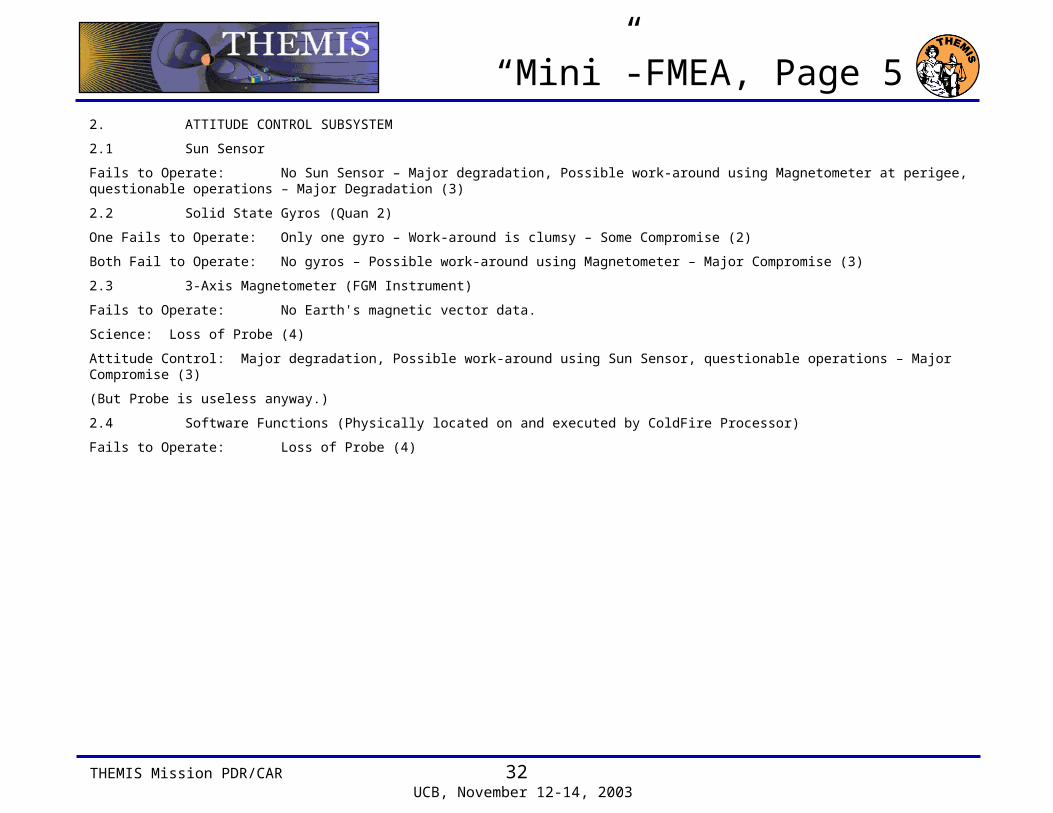
“Mini”-FMEA, Page 52. ATTITUDE CONTROL SUBSYSTEM
2.1 Sun Sensor
Fails to Operate: No Sun Sensor – Major degradation, Possible work-around using Magnetometer at perigee, questionable operations – Major Degradation (3)
2.2 Solid State Gyros (Quan 2)
One Fails to Operate: Only one gyro – Work-around is clumsy – Some Compromise (2)
Both Fail to Operate: No gyros – Possible work-around using Magnetometer – Major Compromise (3)
2.3 3-Axis Magnetometer (FGM Instrument)
Fails to Operate: No Earth's magnetic vector data.
Science: Loss of Probe (4)
Attitude Control: Major degradation, Possible work-around using Sun Sensor, questionable operations – Major Compromise (3)
(But Probe is useless anyway.)
2.4 Software Functions (Physically located on and executed by ColdFire Processor)
Fails to Operate: Loss of Probe (4)

THEMIS Mission PDR/CAR 33 UCB, November 12-14, 2003
“Mini”-FMEA, Page 63. REACTION CONTROL SUBSYSTEM
3.1 Software Functions
Fails to Operate: Can't thrust properly – Loss of Probe (4)
3.2 Tanks (Quan 2)
Either Leak, Rupture: Tanks cannot be isolated, loss of fuel – Loss of Probe (4)
3.3 Flight Pressure Transducer
Fails to Operate: No effect – None (1)
3.4 Thermistors
Fail to Operate: No effect – None (1)
3.5 PRTs
Fail to Operate: No effect – None (1)
3.6 Pressure/Vent Valve (Quan 1, Manual)
No Credible Failure: GSE ops only, no effect – None (1)
3.7 Fill/Drain Valve (Quan 1 per Tank, Manual)
No Credible Failure: GSE ops only, no effect – None (1)
3.8 System Filter (Quan 2)
Either Filter Clogs: Cannot access fuel from one Tank. Consequence to THEMIS mission depends upon what orbital position is occupied by the Probe with the clogged RCS filter. Orbits 1 and 2 (outer orbits) need both tanks of fuel to reach EOL. Orbits 3,4,5 (inner orbits) need only one tank of fuel to reach EOL. For outer orbits the Probe may not reach EOL.
Clogged Filter, Probes 1 or 2: Early in life, Major Compromise (3)
Clogged Filter, Probes 1 or 2: Late in life, Loss of Probe (4)
Clogged Filter, Probes 3,4, or 5: Early in life, Some Compromise (2)
Clogged Filter, Probes 3,4, or 5: Late in life, Major Compromise (3)
THEMIS Mission PDR/CAR 34 UCB, November 12-14, 2003
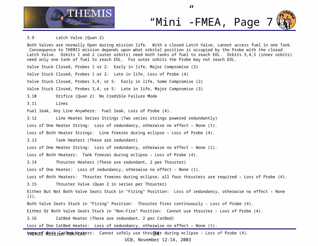
“Mini”-FMEA, Page 73.9 Latch Valve (Quan 2)
Both Valves are normally Open during mission life. With a closed Latch Valve, cannot access fuel in one Tank. Consequence to THEMIS mission depends upon what orbital position is occupied by the Probe with the closed Latch Valve. Orbits 1 and 2 (outer orbits) need both tanks of fuel to reach EOL. Orbits 3,4,5 (inner orbits) need only one tank of fuel to reach EOL. For outer orbits the Probe may not reach EOL.
Valve Stuck Closed, Probes 1 or 2: Early in life, Major Compromise (3)
Valve Stuck Closed, Probes 1 or 2: Late in life, Loss of Probe (4)
Valve Stuck Closed, Probes 3,4, or 5: Early in life, Some Compromise (2)
Valve Stuck Closed, Probes 3,4, or 5: Late in life, Major Compromise (3)
3.10 Orifice (Quan 2) No Credible Failure Mode
3.11 Lines
Fuel leak, Any Line Anywhere: Fuel leak, Loss of Probe (4).
3.12 Line Heater Series Strings (Two series strings powered redundantly)
Loss of One Heater String: Loss of redundancy, otherwise no effect – None (1).
Loss of Both Heater Strings: Line freezes during eclipse – Loss of Probe (4).
3.13 Tank Heaters (These are redundant)
Loss of One Heater String: Loss of redundancy, otherwise no effect – None (1).
Loss of Both Heaters: Tank freezes during eclipse – Loss of Probe (4).
3.14 Thruster Heaters (These are redundant, 2 per Thruster)
Loss of One Heater: Loss of redundancy, otherwise no effect – None (1).
Loss of Both Heaters: Thruster freezes during eclipse; all four thrusters are required – Loss of Probe (4).
3.15 Thruster Valve (Quan 2 in series per Thruster)
Either But Not Both Valve Seats Stuck in "Firing" Position: Loss of redundancy, otherwise no effect – None (1).
Both Valve Seats Stuck in "Firing" Position: Thruster fires continuously – Loss of Probe (4).
Either Or Both Valve Seats Stuck in "Non-Fire" Position: Cannot use thruster – Loss of Probe (4).
3.16 CatBed Heater (These are redundant, 2 per CatBed)
Loss of One CatBed Heater: Loss of redundancy, otherwise no effect – None (1).
Loss of Both CatBed Heaters: Cannot safely use thruster during eclipse – Loss of Probe (4).

THEMIS Mission PDR/CAR 35 UCB, November 12-14, 2003
“Mini”-FMEA, Page 84. COMMUNICATION SUBSYSTEM
4.1 Antenna
Fails to Operate: Loss of Probe (4)
4.2 Transponder
4.2.1 Receiver
Fails to Operate: Loss of Probe (4)
4.2.2 Transmitter
Fails to Operate: Loss of Probe (4)
4.2.3 Diplexer
Fails to Operate: Loss of Probe (4)
4.3 Uplink FPGA on Communications Board
Fails to Operate: Loss of Probe (4)
This FPGA contains the following functions: Uplink Command Interface, Command Verification, Hardware Command Interface
4.4 Command FIFO (One Integrated Circuit Device)
Fails to Operate: Loss of Probe (4)
4.5 Discrete Command Generator (Part of Power Board FPGA)
Fails to Operate: Loss of Probe (4)
THEMIS Mission PDR/CAR 36 UCB, November 12-14, 2003
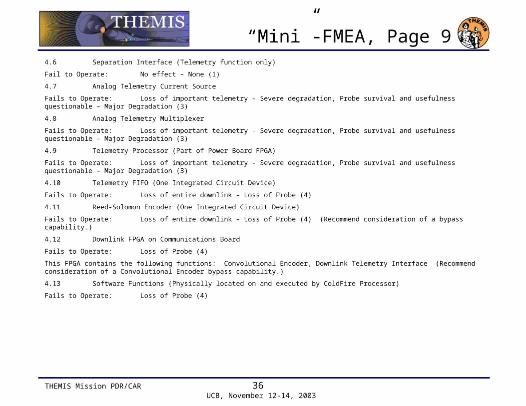
“Mini”-FMEA, Page 94.6 Separation Interface (Telemetry function only)
Fail to Operate: No effect – None (1)
4.7 Analog Telemetry Current Source
Fails to Operate: Loss of important telemetry – Severe degradation, Probe survival and usefulness questionable – Major Degradation (3)
4.8 Analog Telemetry Multiplexer
Fails to Operate: Loss of important telemetry – Severe degradation, Probe survival and usefulness questionable – Major Degradation (3)
4.9 Telemetry Processor (Part of Power Board FPGA)
Fails to Operate: Loss of important telemetry – Severe degradation, Probe survival and usefulness questionable – Major Degradation (3)
4.10 Telemetry FIFO (One Integrated Circuit Device)
Fails to Operate: Loss of entire downlink – Loss of Probe (4)
4.11 Reed-Solomon Encoder (One Integrated Circuit Device)
Fails to Operate: Loss of entire downlink – Loss of Probe (4) (Recommend consideration of a bypass capability.)
4.12 Downlink FPGA on Communications Board
Fails to Operate: Loss of Probe (4)
This FPGA contains the following functions: Convolutional Encoder, Downlink Telemetry Interface (Recommend consideration of a Convolutional Encoder bypass capability.)
4.13 Software Functions (Physically located on and executed by ColdFire Processor)
Fails to Operate: Loss of Probe (4)
THEMIS Mission PDR/CAR 37 UCB, November 12-14, 2003
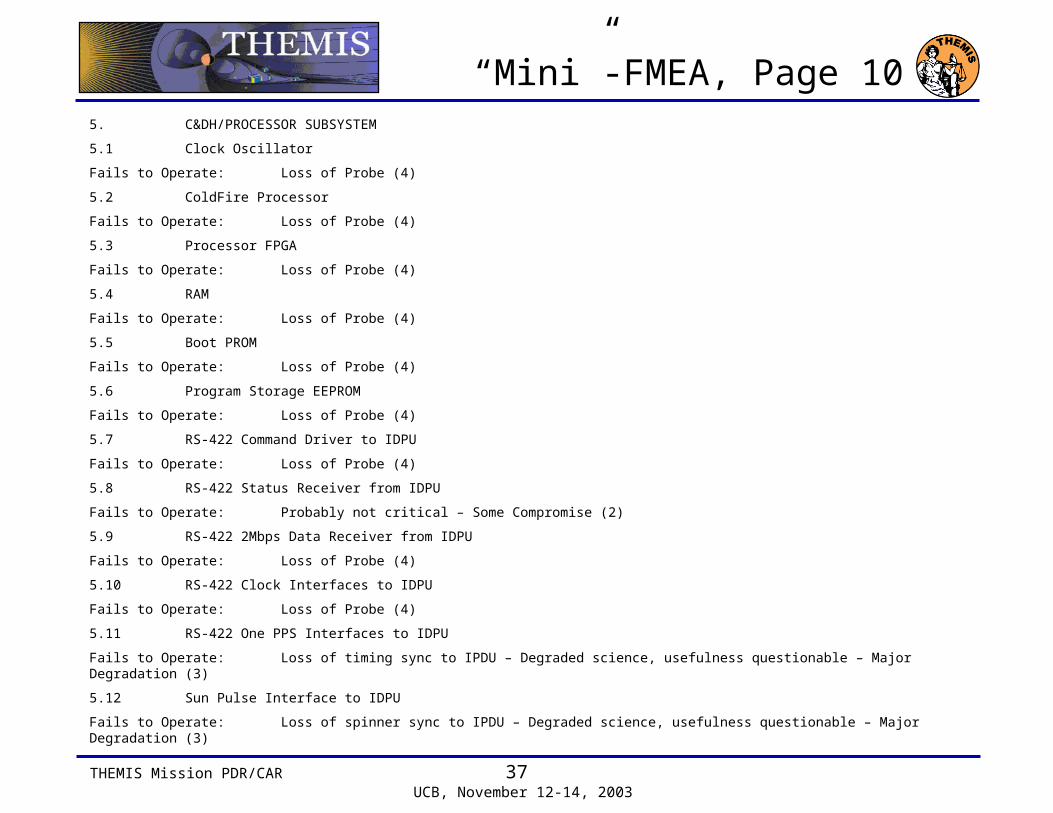
“Mini”-FMEA, Page 105. C&DH/PROCESSOR SUBSYSTEM
5.1 Clock Oscillator
Fails to Operate: Loss of Probe (4)
5.2 ColdFire Processor
Fails to Operate: Loss of Probe (4)
5.3 Processor FPGA
Fails to Operate: Loss of Probe (4)
5.4 RAM
Fails to Operate: Loss of Probe (4)
5.5 Boot PROM
Fails to Operate: Loss of Probe (4)
5.6 Program Storage EEPROM
Fails to Operate: Loss of Probe (4)
5.7 RS-422 Command Driver to IDPU
Fails to Operate: Loss of Probe (4)
5.8 RS-422 Status Receiver from IDPU
Fails to Operate: Probably not critical – Some Compromise (2)
5.9 RS-422 2Mbps Data Receiver from IDPU
Fails to Operate: Loss of Probe (4)
5.10 RS-422 Clock Interfaces to IDPU
Fails to Operate: Loss of Probe (4)
5.11 RS-422 One PPS Interfaces to IDPU
Fails to Operate: Loss of timing sync to IPDU – Degraded science, usefulness questionable – Major Degradation (3)
5.12 Sun Pulse Interface to IDPU
Fails to Operate: Loss of spinner sync to IPDU – Degraded science, usefulness questionable – Major Degradation (3)

THEMIS Mission PDR/CAR 38 UCB, November 12-14, 2003
“Mini”-FMEA, Page 115.13 3.3V Power Switch to EEPROMs
Fails Shorted: No effect other than increased power consumption – None (1)
Fails Open: Cannot re-load flight application software; no effect unless rebooting – Some Compromise (2)
5.14 Bulk Memory
Fails to Operate: Loss of Probe (4)
5.15 Bulk Memory FPGA
Fails to Operate: Loss of Probe (4)
5.16 Software Functions (Physically located on and executed by ColdFire Processor)
Fails to Operate: Loss of Probe (4)
6. BACKPLANE
6.1 I2C Interfaces (Quan 3)
Fails to Operate: Loss of Probe (4)
7. HARNESS AND GROUNDING
7.1 Pyro Arm Plug
No Credible Failure Mode; plug with jumper wires installed before flight.
7.2 RCS Arm Plug
No Credible Failure Mode; plug with jumper wires installed before flight.
THEMIS Mission PDR/CAR 39 UCB, November 12-14, 2003
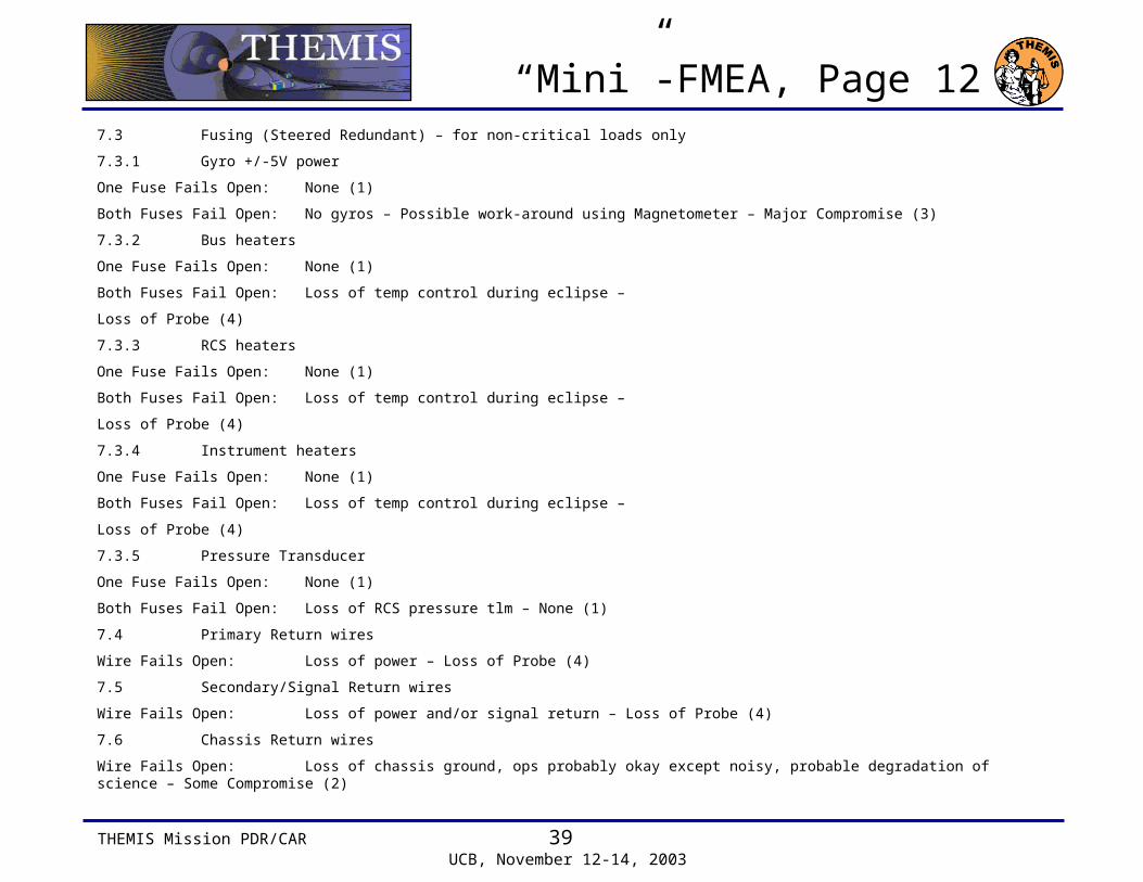
“Mini”-FMEA, Page 127.3 Fusing (Steered Redundant) – for non-critical loads only
7.3.1 Gyro +/-5V power
One Fuse Fails Open: None (1)
Both Fuses Fail Open: No gyros – Possible work-around using Magnetometer – Major Compromise (3)
7.3.2 Bus heaters
One Fuse Fails Open: None (1)
Both Fuses Fail Open: Loss of temp control during eclipse –
Loss of Probe (4)
7.3.3 RCS heaters
One Fuse Fails Open: None (1)
Both Fuses Fail Open: Loss of temp control during eclipse –
Loss of Probe (4)
7.3.4 Instrument heaters
One Fuse Fails Open: None (1)
Both Fuses Fail Open: Loss of temp control during eclipse –
Loss of Probe (4)
7.3.5 Pressure Transducer
One Fuse Fails Open: None (1)
Both Fuses Fail Open: Loss of RCS pressure tlm – None (1)
7.4 Primary Return wires
Wire Fails Open: Loss of power – Loss of Probe (4)
7.5 Secondary/Signal Return wires
Wire Fails Open: Loss of power and/or signal return – Loss of Probe (4)
7.6 Chassis Return wires
Wire Fails Open: Loss of chassis ground, ops probably okay except noisy, probable degradation of science – Some Compromise (2)