Embed Size (px)
Citation preview
Form 4 – Unit 4– Theme 5 – Electricity in the Home Page 1
Theme 5: Electricity in the Home
Static Electricity
WHAT IS STATIC ELECTRICITY?
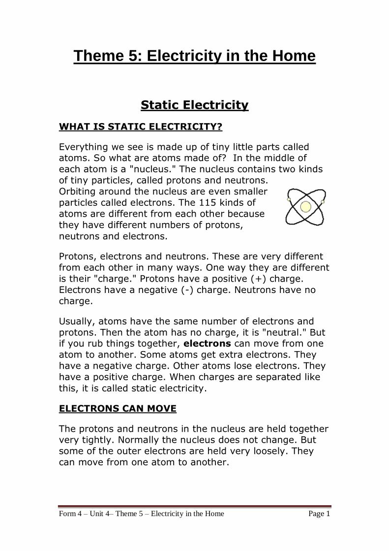
Everything we see is made up of tiny little parts called atoms. So what are atoms made of? In the middle of
each atom is a "nucleus." The nucleus contains two kinds
of tiny particles, called protons and neutrons.
Orbiting around the nucleus are even smaller
particles called electrons. The 115 kinds of
atoms are different from each other because
they have different numbers of protons,
neutrons and electrons.
Protons, electrons and neutrons. These are very different
from each other in many ways. One way they are different
is their "charge." Protons have a positive (+) charge.
Electrons have a negative (-) charge. Neutrons have no
charge.
Usually, atoms have the same number of electrons and
protons. Then the atom has no charge, it is "neutral." But if you rub things together, electrons can move from one
atom to another. Some atoms get extra electrons. They
have a negative charge. Other atoms lose electrons. They
have a positive charge. When charges are separated like
this, it is called static electricity.
ELECTRONS CAN MOVE
The protons and neutrons in the nucleus are held together very tightly. Normally the nucleus does not change. But
some of the outer electrons are held very loosely. They
can move from one atom to another.
Form 4 – Unit 4– Theme 5 – Electricity in the Home Page 2
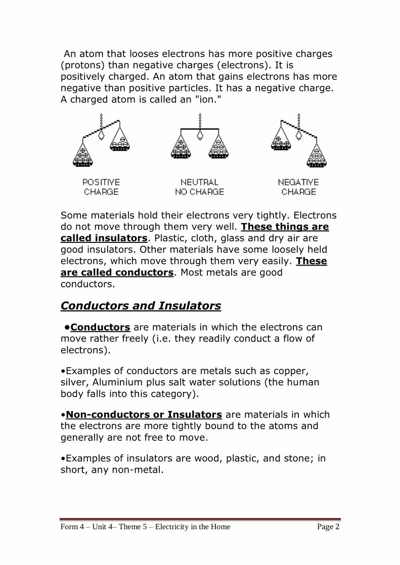
An atom that looses electrons has more positive charges (protons) than negative charges (electrons). It is
positively charged. An atom that gains electrons has more
negative than positive particles. It has a negative charge.
A charged atom is called an "ion."
Some materials hold their electrons very tightly. Electrons do not move through them very well. These things are
called insulators. Plastic, cloth, glass and dry air are
good insulators. Other materials have some loosely held
electrons, which move through them very easily. These
are called conductors. Most metals are good
conductors.
Conductors and Insulators
•Conductors are materials in which the electrons can move rather freely (i.e. they readily conduct a flow of
electrons).
•Examples of conductors are metals such as copper, silver, Aluminium plus salt water solutions (the human
body falls into this category).
•Non-conductors or Insulators are materials in which the electrons are more tightly bound to the atoms and
generally are not free to move.
•Examples of insulators are wood, plastic, and stone; in
short, any non-metal.
Form 4 – Unit 4– Theme 5 – Electricity in the Home Page 3
•The earth acts as a large conductor and has a very large
capacity to absorb charge concentrations from smaller
conductors.
•So any charge on a conductor will be lost if there is a
path to ground.
•Substances that fall between the metals and the
insulators are called semiconductors.
•Semiconductors such as Silicon and Germanium are
widely used in modern electronics since their properties
may be radically altered by the addition of small amounts
of impurity atoms.
•Superconductors are perfect conductors in the sense
that they offer no resistance to the flow of charges.
How can we move electrons from one place to
another?
One very common way is to rub two objects together. If they are made of different materials, and are both
insulators, electrons may be transferred (or moved) from
one to the other. The more rubbing, the more electrons
move, and the larger the charges built up. (Scientists
believe that it is not the rubbing or friction that causes
electrons to move. It is simply the contact between two
different materials. Rubbing just increases the contact
area between them.)
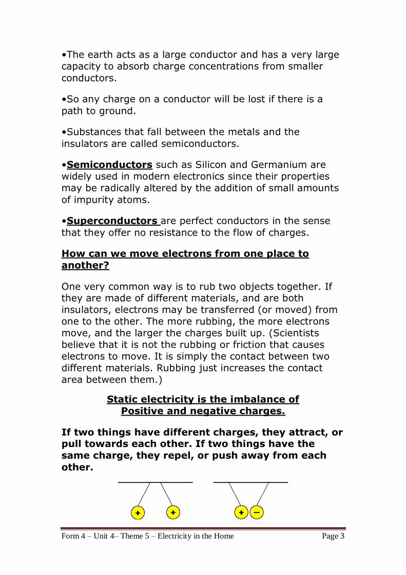
Static electricity is the imbalance of
Positive and negative charges.
If two things have different charges, they attract, or pull towards each other. If two things have the
same charge, they repel, or push away from each
other.
Form 4 – Unit 4– Theme 5 – Electricity in the Home Page 4
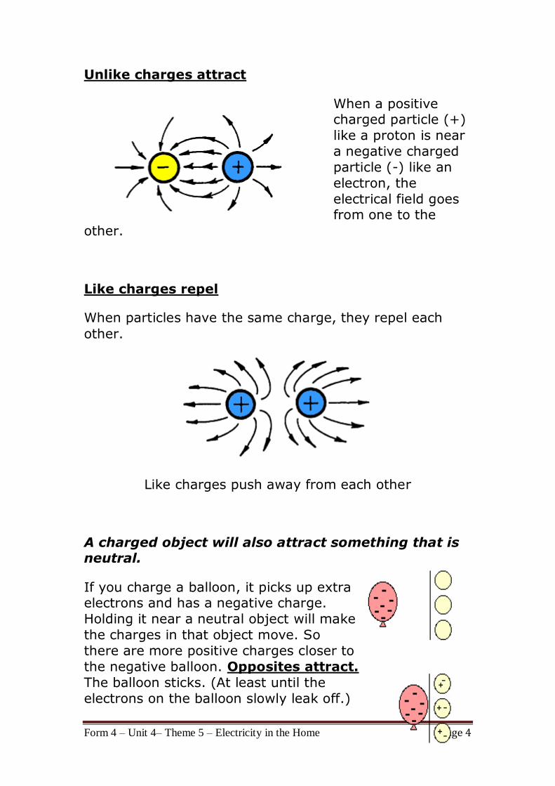
Unlike charges attract
When a positive charged particle (+)
like a proton is near
a negative charged
particle (-) like an
electron, the
electrical field goes from one to the
other.
Like charges repel
When particles have the same charge, they repel each
other.
Like charges push away from each other
A charged object will also attract something that is neutral.
If you charge a balloon, it picks up extra electrons and has a negative charge.
Holding it near a neutral object will make
the charges in that object move. So
there are more positive charges closer to
the negative balloon. Opposites attract.
The balloon sticks. (At least until the
electrons on the balloon slowly leak off.)
Form 4 – Unit 4– Theme 5 – Electricity in the Home Page 5
It works the same way for neutral and positively charged
objects.
So what does all this have to do with shocks? Or hair full of static? When you take off your
wool hat, it rubs against your hair. Electrons
move from your hair to the hat. Now each of
the hairs has the same positive charge.
Remember, things with the same charge repel each other. So the hairs try to get as far from each other as possible.
The farthest they can get is by standing up and away from
the others.
As you walk across a carpet, electrons move from the rug to you. Now you have extra electrons. Touch a door knob
and ZAP! The door knob is a conductor. The electrons
move from you to the knob. You get a shock.
We usually only notice static electricity in the winter when
the air is very dry. During the summer, the air is more
humid. The water in the air helps electrons move off you
more quickly, so you can not build up as big a charge.
In conclusion
Various materials have a tendency of either giving up
electrons and becoming positive (+) in charge or
attracting electrons and becoming negative (-) in charge.
Dry human skin, rabbit fur, cellulose acetate and Perspex
have the greatest tendency to give up electrons when
rubbed on something and become positively ( + )
charged.
Cling film, polyester, and polythene have the greatest
tendency to become negatively charged ( - ) when
rubbed.
CONSERVATION OF CHARGE
Form 4 – Unit 4– Theme 5 – Electricity in the Home Page 6
When we charge something with static electricity, no
electrons are made or destroyed. No new protons appear
or disappear. Electrons are just moved from one place to
another. The net, or total, electric charge stays the same.
This is called the principle of conservation of charge.
Coulomb's Law
(1) Charges may be either positive (like protons) or
negative (like electrons).
(2) Like charges repel; unlike charges attract.
Charge is quantized
Charges on surface
Note that the charged atoms are on the surface of the
material. If electrical charges build up on the outside of a metal, most of them will dissipate into the metal, similar
to an electrical current.
Static electricity is formed much better when the air is dry
or the humidity is low.
Form 4 – Unit 4– Theme 5 – Electricity in the Home Page 7
Electric currents
Static electricity sparks consist of the sudden movement
of electrons from a negative to positive surface, Direct
current or DC electricity is the continuous movement
of the electrons through a wire.
A DC circuit is necessary to allow the current or steam of
electrons to flow. Such a circuit consists of a source of
electrical energy (such as a battery) and a conducting
wire running from the positive end of the source to the
negative terminal. Electrical devices may be included in
the circuit.
Electrical circuit
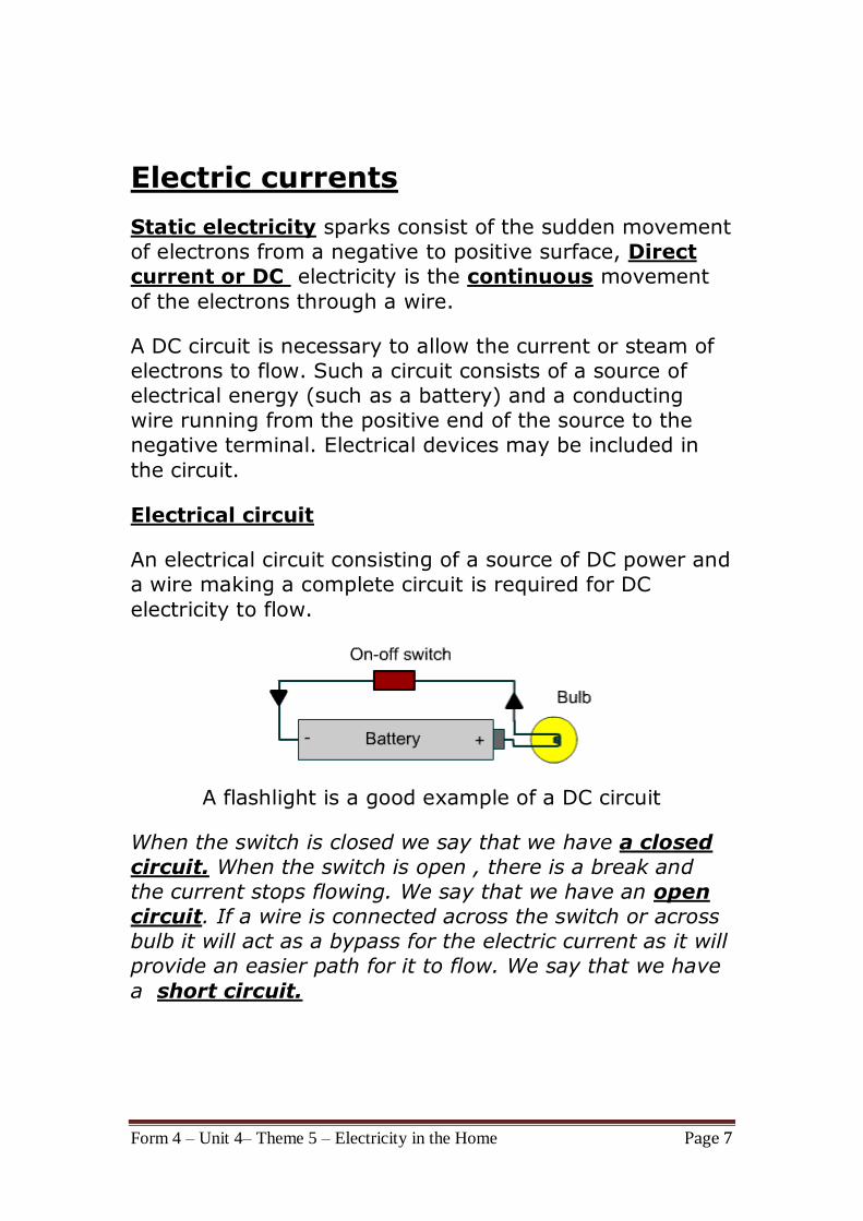
An electrical circuit consisting of a source of DC power and
a wire making a complete circuit is required for DC
electricity to flow.
A flashlight is a good example of a DC circuit
When the switch is closed we say that we have a closed
circuit. When the switch is open , there is a break and
the current stops flowing. We say that we have an open
circuit. If a wire is connected across the switch or across
bulb it will act as a bypass for the electric current as it will
provide an easier path for it to flow. We say that we have
a short circuit.
Form 4 – Unit 4– Theme 5 – Electricity in the Home Page 8
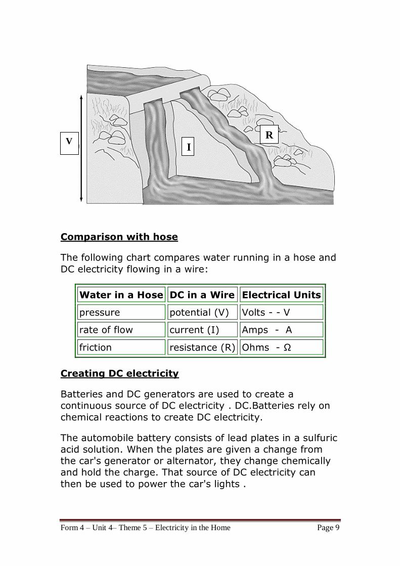
Voltage, current and resistance
The electricity moving through a wire or other conductor
consists of its voltage (V), current (I) and resistance
(R).
Electrical voltage
A potential or pressure builds up at one end of the wire,
due to an excess of negatively charged electrons. It is like water pressure building up in a hose. The pressure causes
the electrons to move through the wire to the area of
positive charge. This potential energy is called Voltage, its
unit of measurement is the Volt ( V ).
Electrical current
The number of electrons is called current and its unit of
measurement is the Ampere or Amp ( A ). Electrical
current is like the rate that water flows through a hose.
Resistance
An Ohm ( Ω ) is the unit of measurement of the electrical
resistance. A conductor like a piece of metal has its atoms
so arranged that electrons can readily pass around the
atoms with little friction or resistance. In an insulator or poor conductor, the atoms are so arranged as to greatly
resist or impede the travel of the electrons. This
resistance is similar to the friction of the hose against the
water moving through it.
Form 4 – Unit 4– Theme 5 – Electricity in the Home Page 9
Comparison with hose
The following chart compares water running in a hose and
DC electricity flowing in a wire:
Water in a Hose DC in a Wire Electrical Units
pressure potential (V) Volts - - V
rate of flow current (I) Amps - A
friction resistance (R) Ohms - Ω
Creating DC electricity
Batteries and DC generators are used to create a
continuous source of DC electricity . DC.Batteries rely on
chemical reactions to create DC electricity.
The automobile battery consists of lead plates in a sulfuric
acid solution. When the plates are given a change from
the car's generator or alternator, they change chemically
and hold the charge. That source of DC electricity can
then be used to power the car's lights .
V I
R
Form 4 – Unit 4– Theme 5 – Electricity in the Home Page 10
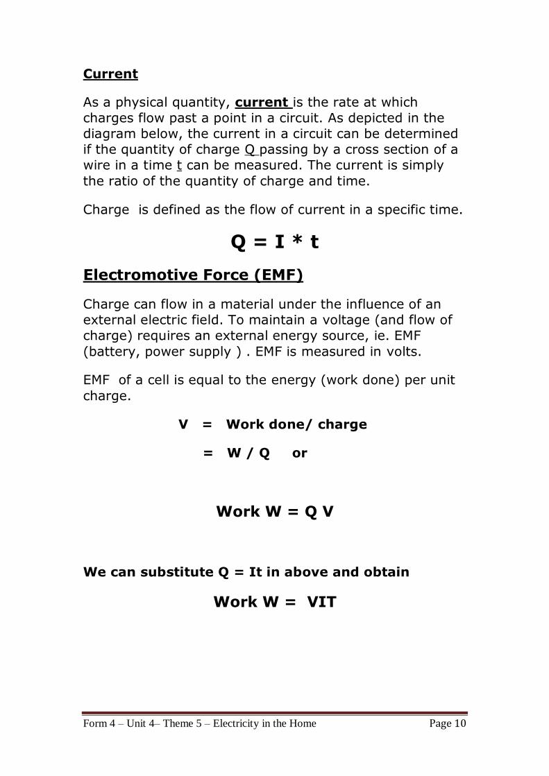
Current
As a physical quantity, current is the rate at which
charges flow past a point in a circuit. As depicted in the
diagram below, the current in a circuit can be determined
if the quantity of charge Q passing by a cross section of a
wire in a time t can be measured. The current is simply
the ratio of the quantity of charge and time.
Charge is defined as the flow of current in a specific time.
Q = I * t
Electromotive Force (EMF)
Charge can flow in a material under the influence of an
external electric field. To maintain a voltage (and flow of
charge) requires an external energy source, ie. EMF
(battery, power supply ) . EMF is measured in volts.
EMF of a cell is equal to the energy (work done) per unit
charge.
V = Work done/ charge
= W / Q or
Work W = Q V
We can substitute Q = It in above and obtain
Work W = VIT
Form 4 – Unit 4– Theme 5 – Electricity in the Home Page 11
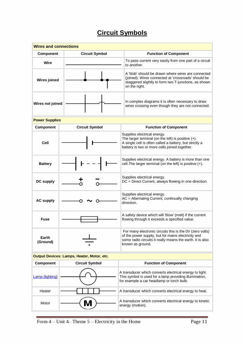
Circuit Symbols
Wires and connections
Component Circuit Symbol Function of Component
Wire To pass current very easily from one part of a circuit to another.
Wires joined
A 'blob' should be drawn where wires are connected (joined). Wires connected at 'crossroads' should be staggered slightly to form two T-junctions, as shown on the right.
Wires not joined
In complex diagrams it is often necessary to draw wires crossing even though they are not connected.
Power Supplies
Component Circuit Symbol Function of Component
Cell
Supplies electrical energy. The larger terminal (on the left) is positive (+). A single cell is often called a battery, but strictly a battery is two or more cells joined together.
Battery
Supplies electrical energy. A battery is more than one cell.The larger terminal (on the left) is positive (+).
DC supply
Supplies electrical energy. DC = Direct Current, always flowing in one direction.
AC supply
Supplies electrical energy. AC = Alternating Current, continually changing direction.
Fuse
A safety device which will 'blow' (melt) if the current flowing through it exceeds a specified value.
Earth (Ground)
For many electronic circuits this is the 0V (zero volts) of the power supply, but for mains electricity and some radio circuits it really means the earth. It is also known as ground.
Output Devices: Lamps, Heater, Motor, etc.
Component Circuit Symbol Function of Component
Lamp (lighting)
A transducer which converts electrical energy to light. This symbol is used for a lamp providing illumination, for example a car headlamp or torch bulb.
Heater
A transducer which converts electrical energy to heat.
Motor
A transducer which converts electrical energy to kinetic energy (motion).
Form 4 – Unit 4– Theme 5 – Electricity in the Home Page 12
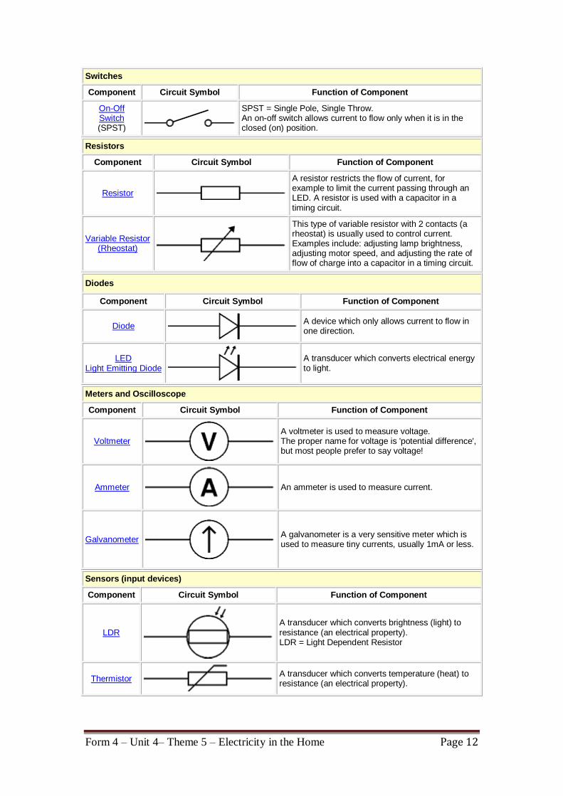
Switches
Component Circuit Symbol Function of Component
On-Off Switch (SPST)
SPST = Single Pole, Single Throw. An on-off switch allows current to flow only when it is in the closed (on) position.
Resistors
Component Circuit Symbol Function of Component
Resistor
A resistor restricts the flow of current, for example to limit the current passing through an LED. A resistor is used with a capacitor in a timing circuit.
Variable Resistor (Rheostat)
This type of variable resistor with 2 contacts (a rheostat) is usually used to control current. Examples include: adjusting lamp brightness, adjusting motor speed, and adjusting the rate of flow of charge into a capacitor in a timing circuit.
Diodes
Component Circuit Symbol Function of Component
Diode
A device which only allows current to flow in one direction.
LED Light Emitting Diode
A transducer which converts electrical energy to light.
Meters and Oscilloscope
Component Circuit Symbol Function of Component
Voltmeter
A voltmeter is used to measure voltage. The proper name for voltage is 'potential difference', but most people prefer to say voltage!
Ammeter
An ammeter is used to measure current.
Galvanometer
A galvanometer is a very sensitive meter which is used to measure tiny currents, usually 1mA or less.
Sensors (input devices)
Component Circuit Symbol Function of Component
LDR
A transducer which converts brightness (light) to resistance (an electrical property). LDR = Light Dependent Resistor
Thermistor
A transducer which converts temperature (heat) to resistance (an electrical property).
Form 4 – Unit 4– Theme 5 – Electricity in the Home Page 13
Ohm's Law for Electrical Circuits
The most fundamental equation in electrical circuits is
called Ohm's Law. Ohm's Law is the equation
V = I * R
This is Ohm’s Law, which states:
The current in a conductor is directly proportional
to the potential difference between its ends
provided that the temperature remains constant.
Since only metals have constant resistance as stipulated
by Ohm’s law, they are called ohmic conductors. All other
materials which conduct current such as electrolytes and
semiconductors etc. do have resistance. But they are
known as non-ohmic conductors since their resistance is
not constant. Hence for non-ohmic conductors the V-I
graph is a curve.
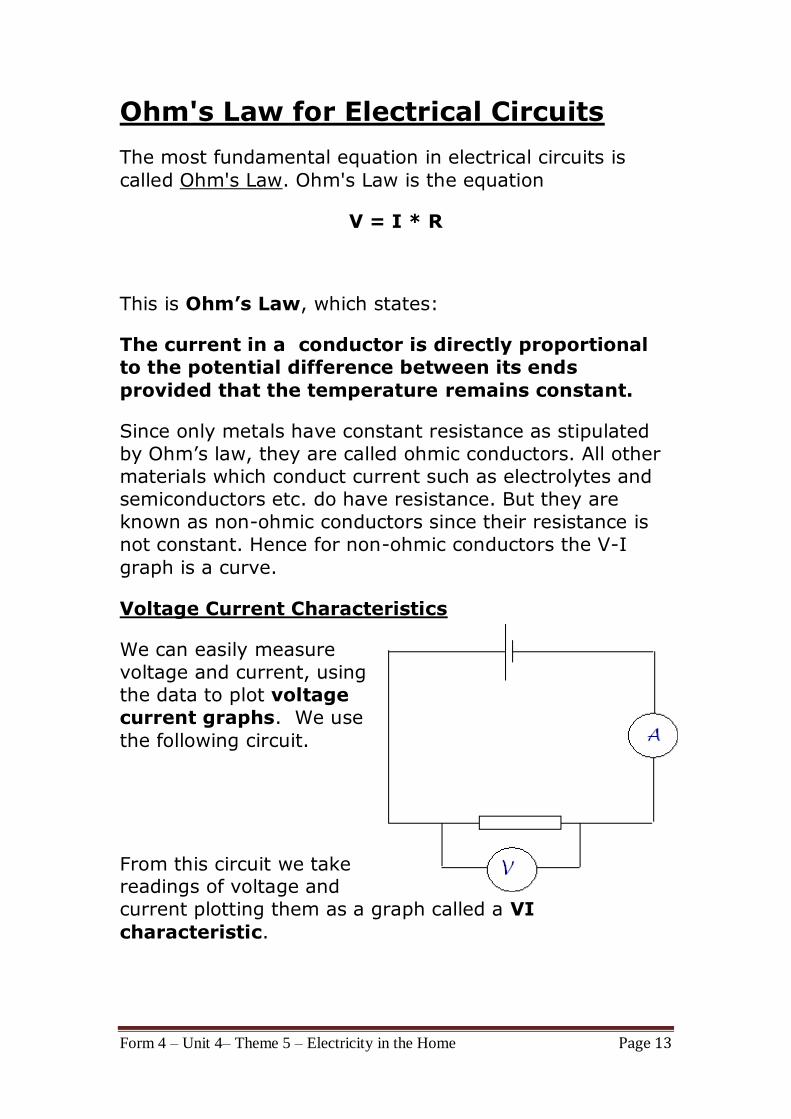
Voltage Current Characteristics
We can easily measure
voltage and current, using
the data to plot voltage
current graphs. We use
the following circuit.
From this circuit we take readings of voltage and
current plotting them as a graph called a VI
characteristic.
Form 4 – Unit 4– Theme 5 – Electricity in the Home Page 14
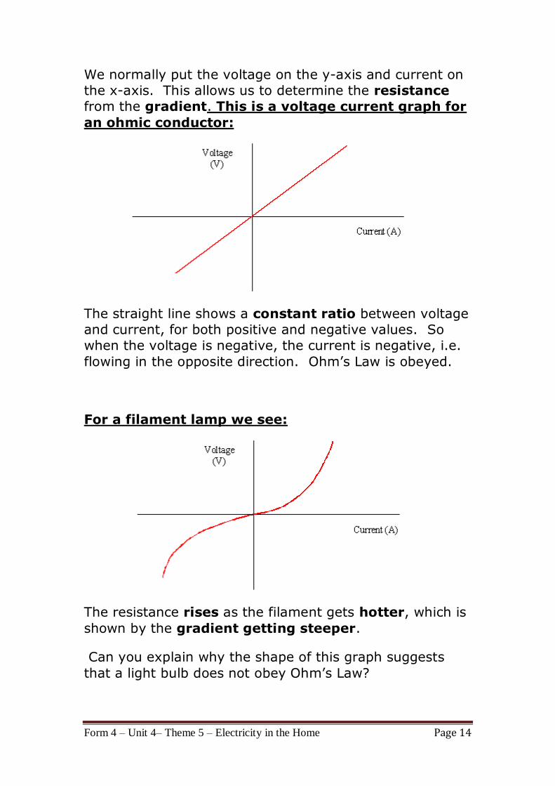
We normally put the voltage on the y-axis and current on
the x-axis. This allows us to determine the resistance
from the gradient. This is a voltage current graph for
an ohmic conductor:
The straight line shows a constant ratio between voltage
and current, for both positive and negative values. So
when the voltage is negative, the current is negative, i.e.
flowing in the opposite direction. Ohm’s Law is obeyed.
For a filament lamp we see:
The resistance rises as the filament gets hotter, which is
shown by the gradient getting steeper.
Can you explain why the shape of this graph suggests
that a light bulb does not obey Ohm’s Law?
Form 4 – Unit 4– Theme 5 – Electricity in the Home Page 15
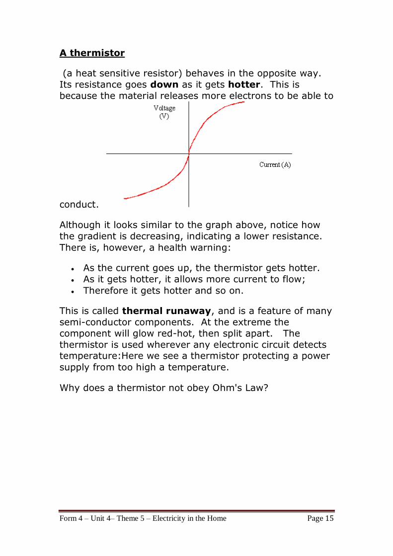
A thermistor
(a heat sensitive resistor) behaves in the opposite way.
Its resistance goes down as it gets hotter. This is
because the material releases more electrons to be able to
conduct.
Although it looks similar to the graph above, notice how
the gradient is decreasing, indicating a lower resistance.
There is, however, a health warning:
As the current goes up, the thermistor gets hotter.
As it gets hotter, it allows more current to flow;
Therefore it gets hotter and so on.
This is called thermal runaway, and is a feature of many
semi-conductor components. At the extreme the
component will glow red-hot, then split apart. The
thermistor is used wherever any electronic circuit detects temperature:Here we see a thermistor protecting a power
supply from too high a temperature.
Why does a thermistor not obey Ohm's Law?
Form 4 – Unit 4– Theme 5 – Electricity in the Home Page 16
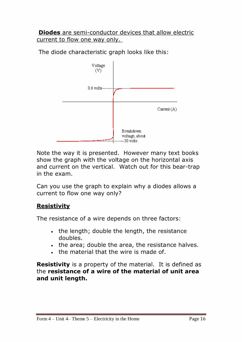
Diodes are semi-conductor devices that allow electric
current to flow one way only.
The diode characteristic graph looks like this:
Note the way it is presented. However many text books show the graph with the voltage on the horizontal axis
and current on the vertical. Watch out for this bear-trap
in the exam.
Can you use the graph to explain why a diodes allows a
current to flow one way only?
Resistivity
The resistance of a wire depends on three factors:
the length; double the length, the resistance
doubles.
the area; double the area, the resistance halves.
the material that the wire is made of.
Resistivity is a property of the material. It is defined as
the resistance of a wire of the material of unit area
and unit length.
Form 4 – Unit 4– Theme 5 – Electricity in the Home Page 17
First, the total length of the wires will effect the amount of
resistance. The longer the wire, the more resistance that
there will be. There is a direct relationship between the
amount of resistance encountered by charge and the
length of wire it must traverse. After all, if resistance occurs as the result of collisions between charge carriers
and the atoms of the wire, then there is likely to be more
collisions in a longer wire. More collisions means more
resistance.
Second, the cross-sectional area of the wires will effect
the amount of resistance. Wider wires have a greater
cross-sectional area. This can be attributed to the lower
amount of resistance which is present in the wider pipe. In
the same manner, the wider the wire, the less resistance
that there will be to the flow of electric charge. When all
other variables are the same, charge will flow at higher
rates through wider wires with greater cross-sectional
areas than through thinner wires.
A third variable which is known to effect the resistance to
charge flow is the material that a wire is made of. Not all
materials are created equal in terms of their conductive ability. Some materials are better conductors than others
and offer less resistance to the flow of charge. Silver is
one of the best conductors, but is never used in wires of
household circuits due to its cost. Copper and aluminum
are among the least expensive materials with suitable
conducting ability to permit their use in wires of household
circuits. The conducting ability of a material is often
indicated by its resistivity. The resistivity of a material is
dependent upon the material's electronic structure and its temperature. For most (but not all) materials, resistivity
increases with increasing temperature.
Form 4 – Unit 4– Theme 5 – Electricity in the Home Page 18
SERIES AND PARALLEL CIRCUITS
What are "series" and "parallel" circuits?
There are two basic ways in which to connect more than
two circuit components: series and parallel. First, an
example of a series circuit:
Series DC circuit
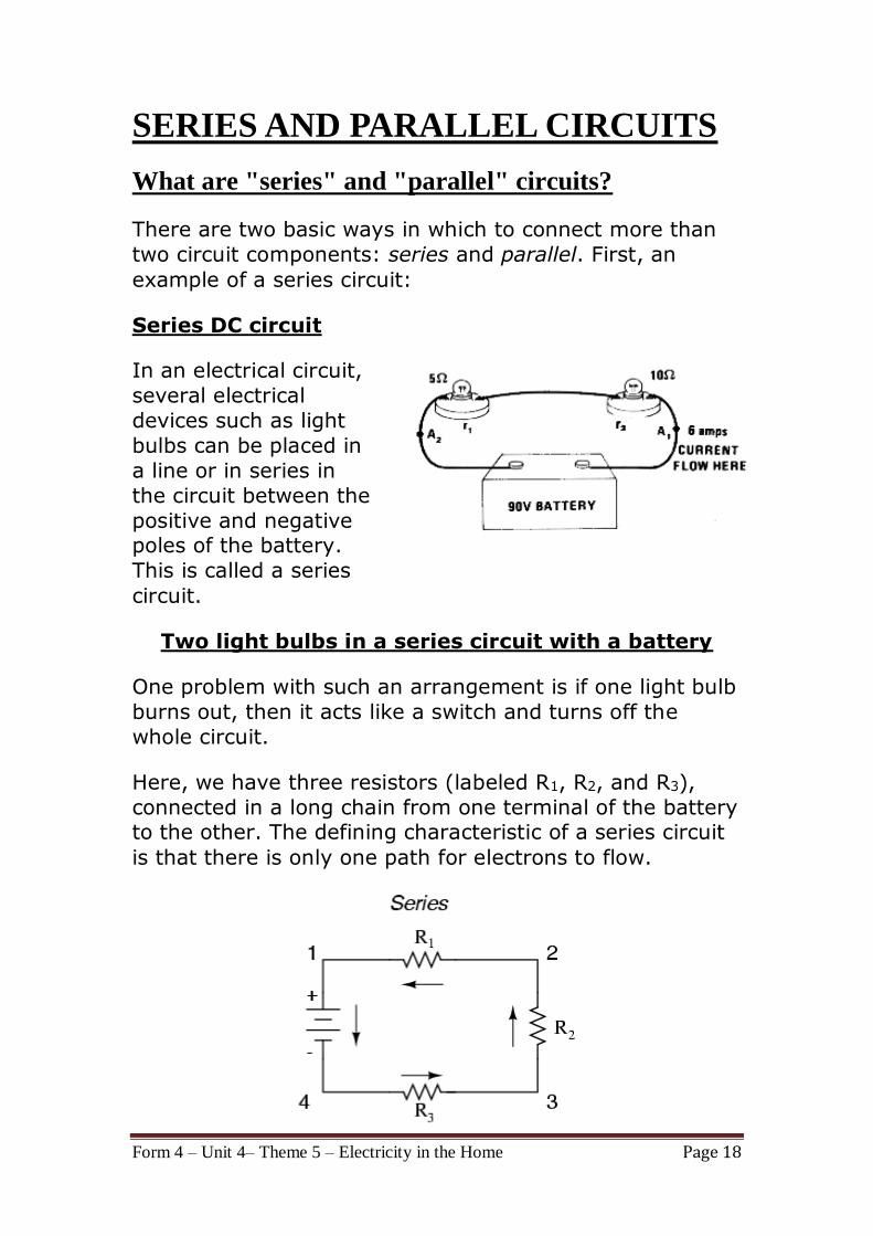
In an electrical circuit,
several electrical
devices such as light
bulbs can be placed in
a line or in series in
the circuit between the
positive and negative poles of the battery.
This is called a series
circuit.
Two light bulbs in a series circuit with a battery
One problem with such an arrangement is if one light bulb
burns out, then it acts like a switch and turns off the
whole circuit.
Here, we have three resistors (labeled R1, R2, and R3),
connected in a long chain from one terminal of the battery to the other. The defining characteristic of a series circuit
is that there is only one path for electrons to flow.
Form 4 – Unit 4– Theme 5 – Electricity in the Home Page 19
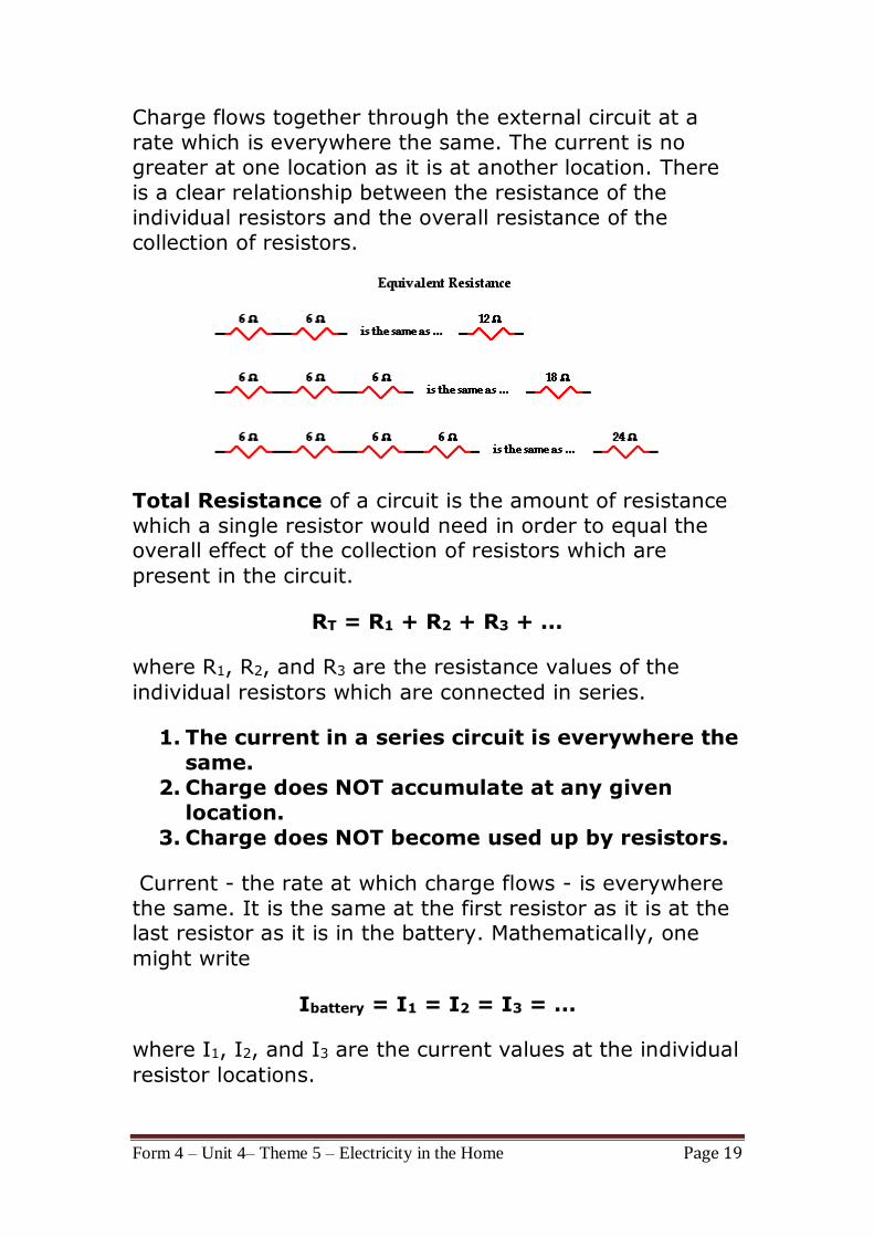
Charge flows together through the external circuit at a
rate which is everywhere the same. The current is no
greater at one location as it is at another location. There
is a clear relationship between the resistance of the
individual resistors and the overall resistance of the
collection of resistors.
Total Resistance of a circuit is the amount of resistance
which a single resistor would need in order to equal the overall effect of the collection of resistors which are
present in the circuit.
RT = R1 + R2 + R3 + ...
where R1, R2, and R3 are the resistance values of the
individual resistors which are connected in series.
1. The current in a series circuit is everywhere the
same.
2. Charge does NOT accumulate at any given
location.
3. Charge does NOT become used up by resistors.
Current - the rate at which charge flows - is everywhere
the same. It is the same at the first resistor as it is at the last resistor as it is in the battery. Mathematically, one
might write
Ibattery = I1 = I2 = I3 = ...
where I1, I2, and I3 are the current values at the individual
resistor locations.
Form 4 – Unit 4– Theme 5 – Electricity in the Home Page 20
In series circuits, the resistor with the greatest resistance
has the greatest voltage drop.
Since the current is everywhere the same within a series circuit, the I value of V = I • R is the same in each of the
resistors of a series circuit. So the voltage drop (V) will
vary with varying resistance. Wherever the resistance is
greatest, the voltage drop will be greatest about that
resistor.
V1 = I • R1 V2 = I • R2 V3 = I • R3
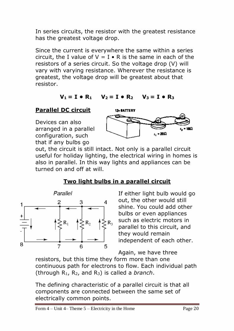
Parallel DC circuit
Devices can also
arranged in a parallel
configuration, such
that if any bulbs go
out, the circuit is still intact. Not only is a parallel circuit useful for holiday lighting, the electrical wiring in homes is
also in parallel. In this way lights and appliances can be
turned on and off at will.
Two light bulbs in a parallel circuit
If either light bulb would go
out, the other would still
shine. You could add other bulbs or even appliances
such as electric motors in
parallel to this circuit, and
they would remain
independent of each other.
Again, we have three
resistors, but this time they form more than one
continuous path for electrons to flow. Each individual path
(through R1, R2, and R3) is called a branch.
The defining characteristic of a parallel circuit is that all
components are connected between the same set of
electrically common points.
Form 4 – Unit 4– Theme 5 – Electricity in the Home Page 21
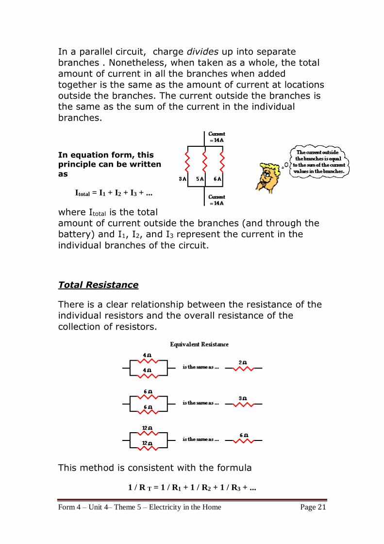
In a parallel circuit, charge divides up into separate
branches . Nonetheless, when taken as a whole, the total
amount of current in all the branches when added
together is the same as the amount of current at locations
outside the branches. The current outside the branches is the same as the sum of the current in the individual
branches.
In equation form, this principle can be written
as
Itotal = I1 + I2 + I3 + ...
where Itotal is the total
amount of current outside the branches (and through the
battery) and I1, I2, and I3 represent the current in the
individual branches of the circuit.
Total Resistance
There is a clear relationship between the resistance of the
individual resistors and the overall resistance of the
collection of resistors.
This method is consistent with the formula
1 / R T = 1 / R1 + 1 / R2 + 1 / R3 + ...
Form 4 – Unit 4– Theme 5 – Electricity in the Home Page 22
Voltage Drops for Parallel Branches
In a parallel circuit, a charge does not pass through every
resistor; rather, it passes through a single resistor. Thus,
the entire voltage drop across that resistor must match
the battery voltage. It matters not whether the charge
passes through resistor 1, resistor 2, or resistor 3, the
voltage drop across the resistor which it chooses to pass
through must equal the voltage of the battery. Put in
equation form, this principle would be expressed as
Vbattery = V1 = V2 = V3 = ...
If three resistors are placed in parallel branches and
powered by a 12-volt battery, then the voltage drop
across each one of the three resistors is 12 volts. A
charge flowing through the circuit would only encounter
one of these three resistors and thus encounter a single
voltage drop of 12 volts.
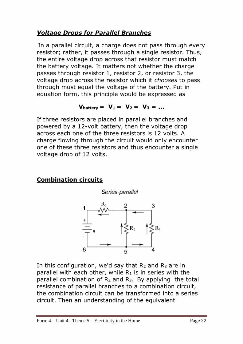
Combination circuits
In this configuration, we'd say that R2 and R3 are in
parallel with each other, while R1 is in series with the
parallel combination of R2 and R3. By applying the total
resistance of parallel branches to a combination circuit,
the combination circuit can be transformed into a series
circuit. Then an understanding of the equivalent

Form 4 – Unit 4– Theme 5 – Electricity in the Home Page 23
resistance of a series circuit can be used to determine the
total resistance of the circuit.
Series and parallel resistor configurations have very
different electrical properties.
In a series circuit, all components are connected
end-to-end, forming a single path for electrons to
flow. Current I is the same in all resistors while
voltage is different across each resistor.(depends on
the resistance)
In a parallel circuit, all components are connected
across each other, forming exactly two sets of electrically common points. The voltage drop is the
same across all resistors while the current is different
in each resistor (depends on resistance)
A "branch" in a parallel circuit is a path for electric
current formed by one of the load components (such
as a resistor).