Embed Size (px)
Citation preview

TheHubbleSpaceTelescopeOpticalSystemsFailureReport
I
[ f-- -_. ",..
lil ) ....,- IJ [
[
I ', / '
: i
/
/
November 1990
National Aeronautics and
Space Administration
"_-gC :I_! e ", ,"(;qASA-l"m-!@3n-43) IH}_ i!9_gL:_ ._._ ! T I ' _" {_
,PTICAL :_Y)T.,-mg FAILU',#._ !,',i-:P_'-_i,,T (N_,SA)
I07 ',_ CqCL 03A
';3/::_9
_,91-12'_37

TheHubbleSpaceTelescopeOpticalSystemsFailureReport
November 1990
National Aeronautics and
Space Administration ORIGINALCONTAINS
COLORiLLUSTRATfONS


THE HUBBLE SPACE TELESCOPE
OPTICAL SYSTEMS FAILURE REPORT
Dr. Lew Allen, Chairman
Director, Jet Propulsion Laboratory
Dr. Roger 1Angel
Professor of Astronomy, Steward Observatory
University of Arizona
Head, Optics Branc_ Technology Division
NASA/Goddard Space Flight Center
Associate Administrator for Safety and Mission QualityNASA Headquarters
l,,¢
Professor Robert R. Shannon
Director, Optical Sciences Center
University of Arizona
Mr. Charles P. Spoelh_" _"
Vice President (Retired), Eastman Kodak Company

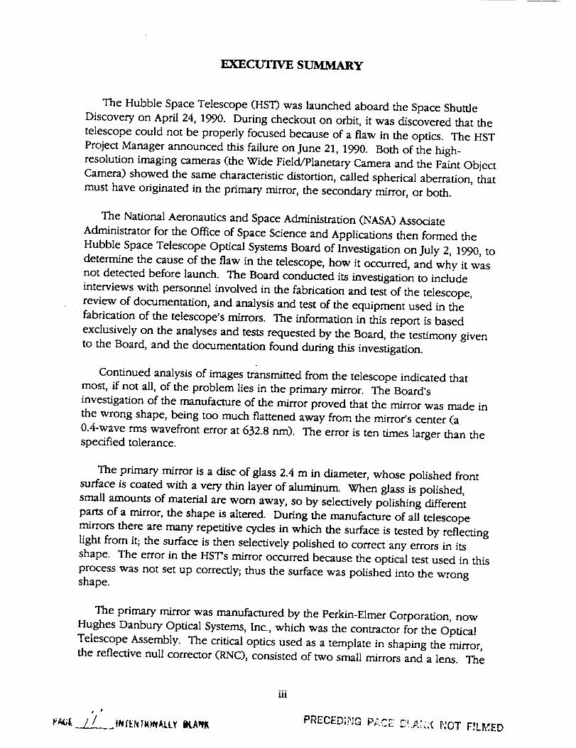
The Hubble SpaceTelescope (HST) was launched aboard the SpaceShuttleDiscovery on April 24, 1990. During checkout on orbit, it was discovered that thetelescopecould not be properly focused becauseof a flaw in the optics. The HSTProjectManagerannounced this failure on June 21, 1990. Both of the high-resolution imaging cameras(the Wide Field/Planetary Cameraand the Faint ObjectCamera)showed the samecharacteristicdistortion, called spherical aberration, thatmust have originated in the primary mirror, the secondarymirror, or both.
The National Aeronauticsand SpaceAdministration (NASA)AssociateAdministrator for the Office of SpaceScienceand Applications then formed theHubble SpaceTelescopeOptical SystemsBoard of Investigation on July 2, 1990,todetermine the causeof the flaw in the telescope,how it occurred, and why it wasnot detected before launch. The Board conducted its investigation to include
interviews with personnel involved in the fabrication and test of the telescope,
review of documentation, and analysis and test of the equipment used in the
fabrication of the telescope's mirrors. The information in this report is based
exclusively on the analyses and tests requested by the Board, the testimony given
to the Board, and the documentation found during this investigation.
Continued analysis of images transmitted from the telescope indicated that
most, ff not all, of the problem lies in the primary mirror. The Board's
investigation of the manufacture of the mirror proved that the mirror was made in
the wrong shape, being too much flattened away from the mirror's center (a
0.4-wave rms wavefront error at 632.8 rim). The error is ten times larger than the
specified tolerance.
The primary mirror is a disc of glass 2.4 m in diameter, whose polished from
surface is coated with a very thin layer of aluminum. When glass is polished,
small amounts of material are worn away, so by selectively polishing different
parts of a mirror, the shape is altered. During the manufacture of all telescope
mirrors there are many repetitive cycles in which the surface is tested by reflecting
light from it; the surface is then selectively polished to correct any errors in its
shape. The error in the HST's mirror occurred because the optical test used in this
process was not set up correcdy; thus the surface was polished into the wrong
shape.
The primary mirror was manufactured by the Perkin-Elmer Corporation, now
Hughes Danbury Optical Systems, Inc., which was the contractor for the Optical
Telescope Assembly. The critical optics used as a template in shaping the mirror,
the reflective null corrector (RNC), consisted of two small mirrors and a lens. The
iii
PAGI, L_ INIENTW_ALLY ILANIt PRECED_?_ P;_C_ _!._,_!(I_OT FILCHED
RNC was designed and built by the Perkin-Elmer Corporation for the HST Project.
This unit had been preserved by the manufacturer exactly as it was during the
manufacture of the mirror. When the Board measured the RNC, the lens was
incorrectly spaced from the mirrors. Calculations of the effect of such
displacement on the primary mirror show that the measured amount, 1.3 mm,
accounts in detail for the amount and character of the observed image blurring.
No verification of the reflective null corrector's dimensions was carried out by
Perkin-Elmer after the original assembly. There were, however, clear indications
of the problem from auxiliary optical tests made at the time, the results of which
have been studied by the Board. A special optical unit called an inverse null
corrector, designed to mimic the reflection from a perfect primary mirror, was built
and used to align the apparatus; when so used, it clearly showed the error in the
reflective null corrector. A second null corrector, made only with lenses, was used
to measure the vertex radius of the finished primary mirror. It, too, clearly showed
the error in the primary mirror. Both indicators of error were discounted at the
time as being themselves flawed.
The Perkin-Elmer plan for fabricating the primary mirror placed complete
reliance on the reflective null corrector as the only test to be used in both
manufacturing and verifying the mirror's surface with the required precision.
NASA understood and accepted this plan. This methodology should have alerted
NASA management to the fragility of the process and the possibility of gross error,
that is, a mistake in the process, and the need for continued care and
consideration of independent measurements.
The design of the telescope and the measuring instruments was performed well
by skilled optical scientists. However, the fabrication was the responsibility of the
Optical Operations Division at the Perkin-Elmer Corporation (P-E), which was
insulated from review or technical supervision. The P-E design scientists,
management, and Technical Advisory Group, as well as NASA management and
NASA review activities, all failed to follow the fabrication process with reasonable
diligence and, according to testimony, were unaware that discrepant data existed,
although the data were of concern to some members of P-E's Optical Operations
Division. Reliance on a single test method was a process which was clearly
vulnerable to simple error. Such errors had been seen in other telescope
programs, yet no independent tests were planned, although some simple tests to
protect against major error were considered and rejected. During the critical time
period, there was great concern about cost and schedule, which further inhibited
consideration of independent tests.
The most unfortunate aspect of this HST optical system failure, however, is that
the data revealing these errors were available from time to time in the fabrication
iv

process, but were not recognized and fully investigated at the time. Reviews were
inadequate, both internally and externally, and the engineers and scientists who
were qualified to analyze the test data did not do so in sufficient detail.
Competitive, organizational, cost, and schedule pressures were all factors in
limiting full exposure of all the test information to qualified reviewers.
V


CONTENTS
I
II
III
IV
V
VI
VII
VIII
IX
X
INTRODUCTION
THE HUBBLE SPACE TELESCOPE MISSION
PROGRAM HISTORY AND MANAGEMENT
A. ResponsibilitiesB. Environment
OPTICAL TELESCOPE ASSEMBLY
A. HST Optical Design
B. Optical TestingC. Null Correctors and Optics
D. PolishingE. Final Tests
THE FAILURE
IDENTIFICATION OF THE FAILURE
A. Onboard Data
B. Sources of Error
HOW THE ERROR OCCURRED
A. Introduction
B. Metering Rod Measurements
QUALITY ASSURANCE OBSERVATIONS
WHY THE ERROR WAS NOT DETECTED PRIOR TO FLIGHT
A. Factual Statements
B. Judgmental Statements
LESSONS LEARNED
a.
B.
C.
D.
E.
F.
Identify and Mitigate Risk
Maintain Good Communication Within the Project
Understand Accuracy of Critical Measurements
Ensure Clear Assignment of Responsibility
Remember the Mission During Crisis
Maintain Rigorous Documentation
GLOSSARY
1-1
2-1
3-1
3-1
3-4
4-1
4-1
4-1
4-1
4-64-7
5-1
6-1
6-1
6-2
7-1
7-1
7-1
8-1
9-1
9-1
9-2
10-1
10-1
10-2
10-2
10-310-4
10-4
11-1
vii PREC_5,::,_ r e C,_, _..,-,,_a t,_i r_Lk,,L:LJ

APPENDIX A
APPENDIX B
APPENDIX C
APPENDIX D
APPENDIX E
CHARTER AND MEMBERSHIP OF THE BOARD
SUMMARY OF PROCEEDINGS
Attachment 1 HST Independent Optical ReviewPanel Findings
TUTORIAL ON SPHERICAL AND COMA ABERRATIONA. Introduction
B. Spherical Aberration
C. Correcting for Spherical AberrationD. Field of View
E. Coma Aberration
F. Correcting Coma and Spherical AberrationsAcross the Field
DESCRIPTIVE SUMMARY OF INTERFEROGRAMS
A. Final Test of the Primary Mirror
B. Refractive Null Corrector Test of the Primary Mirror
C. Inverse Null Corrector Fringes
D. Secondary Mirror Test Interferogram
HST PERFORMANCE BASED ON AS-BUILT DATA
Tables
2-1.
E-1.
E-2.
HST scientific instrument specifications.
HST OTA paraxial design parameters.
HST OTA paraxial as-built parameters.
Figures
2-1.
3-1.
3-2.
4-1.
4-2.
4-3.
5-1.
A-1
B-1
B-1-1
C-1C-1
C-1
C-3C-3C-4
C-4
D-1
D-1
D-5
D-6D-11
E-1
2-3
E-2
E-3
Optical Telescope Assembly. 2-2
Hubble Space Telescope responsibilities. 3-2
MSFC's Hubble Space Telescope responsibilities. 3-3
Two-element refractive null corrector. 4-3
Reflective null corrector. 4-4
Inverse null corrector inserted below the reflective null corrector. 4-5
Encircled energy versus arcsecond radius of image
produced by the HST. 5-2
,,°
Vlll

6-1.
6-2.
6-3.
6-4.
7-1.
7-2.
7-3.
7-4.
7-5.
C-1.
C-2.
C-3.
C-4.
D-1.
D-a,
D°3.
D-4.
Planetary Camera images versus computer simulations.
Comparison of 1982 and 1990 inverse null corrector data.
The 1990 spacing measurement between the field lens
and the lower mirror of the reflective null corrector, using
an optical test.
The 1990 spacing measurement between the lower mirror
vertex and the field lens of the reflective null corrector,
using a mechanical technique.
Position of metering rods used to space opticalelements in the reflective null corrector.
Metering rod (B rod) used to space the field lensand the center of curvature of the lower mirror in
the reflective null corrector.
Metering rod in position between the field lensand the center of curvature of the lower mirror in
the reflective null corrector.
Displacement due to the interferometer focusing on
the field cap instead of the metering rod.
Top view of the field cap, showing the aperture and thearea where the antireflective coating had broken away.
Light-path comparison between spheric and aspheric mirrors.
Image distortion due to spherical and coma aberration.
The HST's Ritchey-Chretien optical system.
Image-plane enlargement of the HST Ritchey-Chretien
optical system.
RNC interferogram of the primary mirror, taken
in February 1982.
RvNC interferogram of the primary mirror, taken
in May 1981.
INC interferogram of the reflective null corrector, takenin February 1981.
Hindle Shell interferogram of the secondary mirror,taken August 31, 1981.
6-10
6-12
7-2
7-3
7-5
7-8
7-9
C-2
C-5
C-7
C-8
D-3
D-7
D-9
D-13
ix

CHAIrrER I
INTRODUCTION
The rough grinding operation for the Hubble Space Telescope began in
December 1978, at the Perkin-Elmer Corporation, in Wilton, Connecticut. The
mirror was then transferred to Perkin-Elmer in Danbury, Connecticut, now Hughes
Danbury Optical Systems, Inc. (HDOS), where polishing was completed in April
1981, and the mirror was accepted as ready for reflective coating. The final post-
coating test was made in February 1982.
Approximately two months after launch, on June 21, 1990, the Hubble Space
Telescope Project Manager announced that there was a major flaw in one or both
of the mirrors in the Optical Telescope Assembly. Dr. Lennard Pisk, Associate
Administrator for the Office of Space Science and Applications, in accordance with
the procedures of the HST Contingency Plan, established the Hubble Space
Telescope Optical Systems Board of Investigation to determine the relevant facts.
A copy of the Board's charter, incorporated in a letter of authorization to the
Chairman, and a list of the members of the Board are presented in Appendix A ofthis report.
The Board, in accordance with its charter, impounded all relevant
documentation and equipment at the HDOS facili W. With the assistance of HDOS
personnel and NASA HST Project and Program management, the Board reviewed
documents, interviewed personnel, and analyzed and tested the equipment used
during the fabrication of the mirrors.
The first meeting of the Board was held in Washington, DC on July 5 and 6,
1990, and the subsequent meetings were held at HDOS. A summary of all the
Board meetings and attendees can be found in Appendix B.
The investigation was quickly directed to the fabrication and testing of the
primary mirror. The test equipment used during the final shaping and polishing of
the primary mirror was found in 1990 in essentially the same configuration as it
had been when used in 1980 through 1982.
Another investigating body, the Independent Optical Review Panel, was formed
by the HST Project to examine the on-orbit data and recommend actions to
maximize the scientific utility of the HST. One of the principal concerns of the
Independent Optical Review Panel is the impact of the spherical aberration
discovered in the HST primary mirror. The results and findings of the HST Optical
Systems Board of Investigation will undoubtedly assist the Independent Optical
1-1

ReviewPanel in its work. (An early report of the Panel'sfindings is included inAppendix B.)
This report of the Board's investigationdescribesthe resultsof the analysisandtestof the equipment used during fabrication and setsforth the conclusionswhichcan be drawn. It is difficult to reconstruct the exact events of the time, particularly
since the status of the documentation is poor. It is also difficult to consider fairly
the pressures of the time in question when cost and schedule were issues of crisis
proportions. Therefore, the Board's judgments clearly benefit from hindsight, with
the clear knowledge that an error occurred and should not have occurred.
1-2

CHAPTER II
THE HUBBLE SPACE TELESCOPE MISSION
The HST was designed to be the first of the great space observatories. It was
launched aboard the Space Shuttle and placed in an Earth orbit approximately 607
kilometers in altitude. The expected life of the telescope is about 15 years, with
instrument changeouts every 3 to 5 years.
The goal of the mission is to extend our knowledge of the universe. A space-
based telescope has the advantage of being in an environment free of the
turbulence and absorption of the Earth's atmosphere. Prior to this mission,
astronomical telescopes in space, such as the Einstein Observatory (HEAO-2) and
the Infrared Astronomical Satellite (IRAS), had been designed to explore new
wavelength bands not transmitted through the atmosphere. The HST was the first
space telescope designed to overcome the blurring of images caused by the
atmosphere. The inherent resolution of a precisely made telescope is in
proportion to its diameter, and the large 2.4-m aperture of HST promised images
ten times sharper than the best images from the ground.
At the heart of the Optical Telescope Assembly (OTA) is a 2.4-m Ritchey-
Chretien telescope with a focal ratio of f/24. The optical range of the HST extends
from 1,100 to 11,000 angstroms, and the performance quality in the ultraviolet is
u_que. Figure 2-1 illustrates the OTA.
Eight instrument packages are attached to the HST: two cameras (Wide
Field/Planetary Camera and Faint Object Camera), two spectrographs (Faint Object
Spectrograph and High-Resolution Spectrograph), one photometer (High-Speed
Photometer), and three fine guidance sensors. Each fine guidance sensor packagealso contains a wavefront sensor. Table 2-1 lists the HST and scientific instrument
specifications.
2-1

r- FINEPRIMARY \ GUIDANCE _ AXIAL SCIENTIFIC
APERTURE DOOR --_ MIRROR --_ \SENSORS (3)/INSTRUMENTS (4)
\ CENTRAL \ \ /_1 SECONDARY --_ BAFFLE--k \ \ /
....... i
------_---- , ,,,_,,_,,C.C.._...-7-/I/ \ /ILtll tl I.I I ,,, ,-I \ /
/llj\ STRAY-LIGHT SECONDARY _ FOCAL PLANEBAFFLES MIRROR RADIAL (IMAGE FORMED
BAFFLE SCIENTIFIC HERE)INSTRUMENT
Figure 2-1. Optical Telescope Assembly.
2-2

Table 2-1. HST scientific instrument specifications.
Hubble Space Telescope
WeightLengthDiameter
Optical SystemOptical LengthPrimary MirrorSecondary MirrorField of View
Pointing AccuracyMagnitude RangeWavelength RangeAngular ResolutionOrbitOrbit TimeMission
11,500 kg13m4.2 m at widest
Ritchey-Chretien design Cassegrain telescope57.6 m folded to 6.4 m
2.4 m in diameter0.3 m in diameterSee instruments and sensors below0.007 arcsec for 24 hr
5--29 mv1,100-11,000 angstroms0.1 arcsec at 6,328 angstroms611 km (330 nmi) inclined 28.5 ° from equator
94 minutes per orbit15 years
Faint Object Camera
WeightDimensions
Principal InvestigatorContractor
Optical ModesField of View
Magnitude RangeWavelength Range
315 kg0.9 x 0.9 x 2.2 m
F. D. Macchetto, European Space Agency (ESA)ESA (Dornier, Matra Corp.)f/96, f/4811.2, 22 arcsec 25-28 my
1,150-6,500 angstroms
Wide Field/Planetary Camera
WeightDimensions
Principal InvestigatorContractor
Optical ModesField of View
Magnitude RangeWavelength Range
268 kgCamera: 1 x 1.3 x 0.5 mRadiator: 0.8 x 2.2 m
J. A. Westphal, California Institute of TechnologyJet Propulsion Laboratoryf/12.9 (WF); f/30 (P)160, 66 arcsec 29--28 mv1,150-11,000 angstroms
GSFC High-Resolution Spectrograph
WeightDimensions
Principal InvestigatorContractor
AperturesResolution
Magnitude RangeWavelength Range
315 kg0.9 x 0.9 x 2.2 m
J. C. Brandt, NASA/Goddard Space Flight CenterBall Aerospace2 arcsec 2 target, 0.25 arcsec 2 science2,000--100,00017-11 my1,050--3,200 angstroms
2-3

Table 2-1. HST scientific instrument specifications (continued).
Faint Object Spectrograph
WeightDimensions
Principal InvestigatorContractor
AperturesResolution
Magnitude Range
Wavelength Range
306 kg0.9 x 0.9 x 2.2 m
R. J. Harms, NASA/Ames Research CenterMartin Marietta CorporationO. 1-4.3 arcsec 2250, 1,30019-26 my
1,100-8,000 angstroms
High-Speed Photometer
WeightDimensions
Principal InvestigatorContractor
AperturesResolution
Magnitude RangeWavelength Range
270 kg0.9 x 0.9 x 2.2 m
R. Bless, University of WisconsinUniversity of Wisconsin0.4, 1.0, 10.0 arcsec 2Filter-defined
<24 my1,200-7,500 angstroms
Fine Guidance Sensors
WeightDimensionsContractorAstrometric ModesPrecision
Measurement SpeedField of View
Magnitude RangeWavelength Range
218 kg0.5x lx 1.6m
Perkin-Elmer CorporationStationary and moving target, scan0.002 arcsec 210 stars in 10 minutesAccess: 60 arcmin 2Detect: 5 arcsec 2
4-18.5 my4,670-7,000 angstroms
Information provided by Lockheed Missiles and Space Company, Inc.
2-4
CHAPTER 111
PROGRAM HISTORY AND MANAGEMENT
A. RESPONSIBILITIES
The HST program is the result of a cooperative effort between NASA and the
European Space Agency, private contractors, and astronomers worldwide. The
management responsibilities included design, development, launch, and daily
operations of the telescope. The NASA Centers and prime contractors involved in
the development of the HST, and their interrelationships, are listed in Figure 3-1.
At NASA Headquarters, the director of the Astrophysics Division, who reports
to the NASA Associate Administrator for the Office of Space Science and
ApplicatiQns, has overall authority for the HST Project. He assigned the NASA HST
Program Manager to ensure that NASA policies and Project goals are maintained
and to administer the schedule and budget. Overall science policy is the
responsibility of the HST Program Scientist.
Marshall Space Flight Center (MSFC) was assigned as lead center for the HST
Project management and tasked with the development of the telescope flight
hardware and the general checkout phase after deployment. Responsibility for
meeting the technical performance goals and for managing the program within
budget and schedule was also with MSFC. Figure 3-2 is the MSFC organizationchart for the HST.
The other NASA Center with a major involvement in the Project is the Goddard
Space Flight Center (GSFC), which was responsible for verifying the performance
of the science instruments. GSFC also controls the daily operations of the HST.
On October 16, 1990, the responsibility for the HST Project (except for the optical
system failure questions) was transferred from MSFC to GSFC.
The two prime contractors for the Project were Lockheed Missiles and Space
Company, Inc. (LMSC) and the Perkin-Elmer Corporation (P-E). LMSC developed
the Support Systems Module (SSM) and supervised many subcontracts; P-E
designed and developed the OTA, including the fabrication of the primary and
secondary mirrors. P-E was also responsible for verification testing and delivery of
the OTA to LMSC, where the OTA was integrated with the other subsystems. In
addition to the OTA, P-E developed the fine guidance sensors and wavefront
sensors used in the HST.
3-1

I
LOCKHEED iMISSILES &
SPACE CO.
-- HST SYSTEMS
ENGINEERING &
INTEGRATION
--SSM DESIGN,
FABRICATION,
ASSEMBLY& VERIFICATION
I
-- HST ASSEMBLY I
& VERIFICATION I-- HST LAUNCH
& ORBIT
VERIFICATION
--HST MISSIONOPERATIONS
PLANNING
-- SUBCONTRACTOR
MANAGEMENT
NASA iHEADQUARTERS
MARSHALL i
SPACEFLIGHT
CENTER
I EUROPEANSPACE
AGENCY
L;:,::::::;CAMERA
PERKIN-
ELMER
CORP.
OTA DESIGN,
FABRICATION,
ASSEMBLY &
ENGINEERING
GODDARD
SPACE FLIGHT
CENTER
-- SCIENTIFIC
INSTRUMENTS (SI)
--SIC&DHSUBSYSTEM
__L__JOHNSON
SPACE
CENTER
I HST/ORBITER/
CREW INTERFACE
::Z°:MAINTENANCEPLANNING
i KENNEDY
SPACE
CENTER
I
I HST/ORBITER
LAUNCHVERIFICATION
LAUNCH
--HST OPERATIONSCONTROLCENTER
& SCIENCE
OPERATIONS
FACILITY
-- HST MISSION
OPERATIONS
--TDRSS
ISPACE TELESCOPE /
SCIENCE II
INSTITUTE II
-- SCIENCE OPERATIONS
PLANNING
--SUPERVISION OF
SCIENCE OPERATIONS
-- SCIENCE &ENGINEERING
i DATA ANALYSIS-- ASTRONOMICALFINDINGS
INFORMATION PROVIDED BY LOCKHEED MISSILES AND SPACE COMPANY, INC.
Figure 3-1. Hubble Space Telescope responsibilities.
3-2

MARSHALL ISPACE FLIGHT
CENTER
I HST iPROJECT
OFFICE
I OPTICAL TELESCOPEASSEMBLY
PROJECT OFFICE
I SUPPORT SYSTEMS IMODULE
PROJECT OFFICE
I SYSTEMS iENGINEERING
OFFICE
I OPERATIONSOFFICE
PROJECTSCIENTIST
PROJECTCHIEF ENGINEER
PROGRAM PLANNINGAND
CONTROL OFFICE
MAINTENANCE ANDREFURBISHMENT
OFFICE
MSFC RESPONSIBILITIES
• HST DEVELOPMENT LEAD CENTER• TOTAL PROJECT MANAGEMENT• OTA DEVELOPMENT• SSM DEVELOPMENT• HST INTEGRATION AND VERIFICATION• ORBITAL VERIFICATION OPERATIONS• MAINTENANCE AND REFURBISHMENT
PLANNING
iii
INFORMATION PROVIDED BY LOCKHEED MISSILES AND SPACE COMPANY, INC.
Figure 3-2. MSFC's Hubble Space Telescope responsibilities.
3-3

Before P-E was selected as the OTA prime contractor, the company was asked
to design and build a smaller hyperbolic mirror in order to demonstrate their
technical capability. A 1.5-m mirror was successfully designed, fabricated, and
tested using the new technologies that would be used for the larger 2.4-m HST
primary mirror. After a competitive bid process, P-E was awarded the HST
contract, based in part on their successful demonstration of the 1.5-m mirror and
on other factors, including their proposed fine guidance sensors.
Because NASA considered the quality of the primary mirror to be a major
challenge, it directed P-E to subcontract with the Eastman Kodak Company to
fabricate a second primary mirror. The fabrication and test methods used at
Eastman Kodak and P-E were entirely different. It was the responsibility of NASA
to review the final specifications of the mirrors and to choose the best one for
flight. The P-E primary and secondary mirrors were selected.
B. ENVIRONMENT
During 1981 and continuing through early 1982, the HST program was beset by
many difficulties. The estimated cost of the P-E contract had increased several-fold
and the schedule had slipped substantially. The fine guidance sensors were
having serious technical problems, and the severity of the challenge to keep the
mirrors sufficiently free from contamination to meet the specifications in ultraviolet
light was just being recognized. The program was threatened with cancellation,
and management ability was questioned. All these factors appear to have
contributed to a situation where NASA and P-E management were likely to be
distracted from supervision of mirror fabrication.
3-4

CHAPTER IV
OPTICAL TELESCOPE ASSEMBLY
A. I-IST OPTICAL DESIGN
The Optical Telescope Assembly in the Hubble Space Telescope is a two-
mirror reflecting telescope very similar to most Earth-based telescopes built in the
last 75 years. These two-mirror telescopes are generally referred to as Cassegrain
telescopes, after the French cleric who first published the design. The OTA is a
special type of Cassegrain telescope called a Ritchey-Chretien (R-C) that has better
optical performance over a larger format in the image plane. The mirrors in the
R-C are slightly more aspheric (have a greater departure from a pure spherical
shape) than in the Cassegrain type, but both types of telescopes are quite
common. The primary mirror in the OTA, the one in which the error exists, is a
2.4-m diameter concave hyperboloid. The 0.3-m diameter secondary mirror is a
convex hyperboloid. This makes the OTA a little less than half the size of the
Hale telescope on Mr. Palomar.
B. OPTICAL TESTING
Spherical mirrors are easy to make and to test, but such mirrors do not produce
good-quality images. The aspheric mirrors used in Cassegrain or R-C telescopes
can produce theoretically perfect images, but their aspheric shape makes them
difficult to test. Because the two mirrors in the OTA are hyperboloids or aspheric
mirrors, special test optics are needed to guarantee that the mirrors are the correct
shape. These special test optics, called null correctors, generate test reference
wavefronts that make the aspheric mirror look spherical to the optician. The null
correctors achieve this effect by projecting an optical template of the desired
aspheric shape that can be designed to be accurate to better than 25 nanometers.
C. _ CORRECI'ORS AND OPTICS
The convex secondary mirror of the OTA was tested in a geometrically perfect
null test with what is called a Hindle Shell test, a modification of the classic Hindle
Sphere test. Because hyperboloids have the property of perfecdy imaging rays
from one focus into the other focus, the Hindle SheLl null corrector is used to
physically implement this test. The Hindle test of the OTA secondary was carried
out precisely as planned, _.nd the shape of this mirror met specification. The
4-1

aspheric shape of the secondary mirror was verified through the use of two
independent tests during fabrication of the component.
In the manufacture of prior telescopes, refractive null correctors (RvNCs), such
as the one shown in Figure 4-1, were used. The combination of the two precisely
made and spaced lenses produces the desired optical template of the concave
aspheric mirror.
Carrying out an unambiguous and accurate test to determine whether a null
corrector is producing the correct optical template is a known difficulty. For the
HST program, Perkin-Elmer concluded that an RvNC would not yield sufficient
precision for testing the figure of the primary mirror, and as a result, a new and
novel reflective null corrector (RNC) was designed. As shown in Figure 4-2, the
Perkin-Elmer RNC consists of two spherical mirrors and one small field lens. (The
more common RNC design contains only a single mirror and a field lens.) In the
P-E design, the shape of the optical template could be precisely predicted simply
by knowing the manufactured dimensions of the two mirrors and the lens,
including the lens material, and the spacings of the three optical elements. Perkin-
Elmer planned to certify the RNC with great care, and they did not plan to do any
independent testing of the mirror.
The RNC was designed to provide easy access to all the optical surfaces in the
null corrector in order to measure these spacings at any time. The spacing
between the two spherical mirrors can be measured by determining the distance
between the centers of curvature of the two mirrors. This measurement is done
interferometrically, using a known metering rod of the desired length. In a similar
manner, the field lens spacing can be measured relative to the center of curvature
of the lower mirror. The spacings need to be correct to 10 _tm to meet
specifications.
This ability to measure the optical element spacings at any time is something
that is not possible with a traditional RvNC, made up of all lenses and no mirrors.
The novel RNC that answered some of the misgivings about the RvNC approach
was one of the factors leading to the award of the HST contract to Perkin-Elmer.
As a check on the position of the Coaxial Reference Interferometer (CORD
used with the RNC, an inverse null corrector (INC) was designed. When swung
under the RNC, the INC would simulate a perfect mirror, just as a perfect primary
mirror would appear with straight fringes when viewed through the RNC
(Figure 4-3).
4-2

PO'NTSOURCE /I OF LIGHT
//r/
/
//
P_mo_ / / ICONVEX i
LENS _ t|
\
\
//
/
t\
\\
/ /
_ I//
NULL CORRECTOR
\/
'_'_ FIEILD LENS
\ --\\X_
T
NOTE: THIS DRAWING NOT TO SCALE
Figure 4-1. Two-element refractive null corrector.
4-3

\\\,]_':'///\\i _
i_\ /_ l \\ , INULLCORRECTOR
_:_'_'_'_"_-_ FIELD LENS
L
l /-- pRIMARY "_
NOTE:THISDRAWINGNOT1"OSCALE
t_tg_r¢ 4-2.Reflective null corrector-
4-4

POINT SOURCE _\
o,_..._I li "_/ I
\ ,/_'\ //\\ /V \,/ V
i1'\\\i_ /it\\
[ i,,\l� _ r # \\
, . , ix iI , ,
l _.EGAT,VE L_.S__ _ I'_"---_CO.CAVEM,RROR
IL-----00mm----iNOTE: THIS DRAWING NOT TO SCALE I
REFLECTIVENULL
CORRECTOR
TINVERSE
NULLCORRECTOR
Figure 4-3. Inverse null corrector inserted below the reflective null corrector.
4-5

Although not considered as a backup or additional check of the optical
template produced by the RNC, an RvNC was built to test the OTA primary during
early stages of polishing and was again used to test the primary mirror during a
measurement of the vertex radius of curvature or "power" of the primary mirror.
The RvNC had to be used for this radius measurement because the RNC had to
have central holes in the two mirrors (just as the primary had a hole) to let the
light through. Because of the holes in the RNC mirrors, it was not possible to see
the location of the vertex of the primary mirror.
"White-light" fringes were used as an initial setup procedure to align the
reference test plate (i.e., the calibrated mirror inserted into the hole of the primary
mirror) for the vertex radius measurement. This measurement was extremely
sensitive to vibration, and the fringes could not be captured on film because of the
short duration and faintness of the images. Several observers were required to
witness that the fringes were seen. When this test was accomplished, a helium-
neon (He-Ne) laser replaced the white-light source in order to take photographs
(interferograms) by which to make the vertex radius measurement.
D. POLISHING
During the polishing of the OTA mirrors, the Hindle test was performed on the
secondary mirror, and its surface was polished until it looked like a pure sphere to
about 0.012-wave rms wavefront error at 632.8 nm. This meant that the surface
was the correct hyperboloid to this same quality, a quality better than that
specified in the contract.
The backup OTA primary mirror was polished at Eastman Kodak Company
using both a refractive and a reflective null corrector of a completely different
design from the Perkin-Elmer version. This mirror matched the templates of the
two null correctors to better than 0.014-wave rms wavefront error at 632.8 run, and
the Board has every reason to believe it is the correct hyperboloidal shape.
The primary mirror now flying in the HST was polished using the Perkin-Elmer
RNC as a guide or template. Again, the fit to the template was better than
0.014-wave rms wavefront error at 632.8 nm, better than the contract specification
for the accuracy of the mirror. Unfortunately, as has been subsequently learned,
there was an error in the template produced by the RNC, thus making the primary
mirror the wrong shape.
4-6

E. FINAL TESTS
An end-to-end test of the OTA would have been very expensive to perform at
the level of accuracy specified for the telescope. The test would have cost on the
order of what the OTA itself cost, because a flat or piano mirror would have been
needed. To test the flat mirror by a single interferogram would have required a
spherical mirror about 15 percent larger than the fiat mirror. Thus the test could
have required two additional mirrors as large as or larger than the OTA primary.
In hindsight, a much less severe test could have been done to check for a gross
error such as did occur. The belief at the time was that if the two mirrors had
each exceeded their individual specifications, only a test at the level of accuracy of
the individual mirrors would have been meaningful. Such a test would have been
very hard to justify because of cost.
Actually, an end-to-end test was done over a 0.3-m diameter aperture to ensure
that the assembled telescope focused where it should. There was no attempt to
use this test as a check on the figure of the primary mirror, apparently because it
was believed that the fraction of the mirror tested was too small to give reliable
results and also because the OTA was mounted horizontally and the distortion due
to gravity was significant.
4-7


CHAgrER V
THE FAILURE
The Level I specification for the HST is to achieve 70 percent encircled energy
in a circle of 0.1-arcsecond radius and to meet a Rayleigh criterion (i.e., image
resolution of two objects) of at least 0,1 arcsecond. Early in the checkout phase of
the mission, it was discovered that the telescope did not meet the above
requirement. Instead, the telescope focused 70 percent encircled energy into a
0.7-arcsecond radius. Figure 5-1 is a plot of the encircled energy percentage
versus radius in arcseconds for both the specified HST performance and the actual
performance.
The problem was initially detected when the "first light" images from both the
Wide Field/Planetary Camera and the Faint Object Camera were analyzed and
major defects were detected. Computer simulation of these images indicated that
0.5-wave rms wavefront spherical aberration at 547 nm existed in the telescope
and not in the instruments. Further verification of the spherical aberration
problem came from the wavefront sensors.
Both on-axis and off-axis data were analyzed in order to determine whether
the primary mirror or the secondary mirror, or perhaps both mirrors, were flawed.
Data taken by the wavefront sensors, the Wide Field/Planetary Camera, and the
Faint Object Camera indicated a significant spherical aberration wavefront error.
Although some coma appeared in the off-axis results taken by the fine guidance
sensors, the amount of coma was small and the conclusion was reached that the
primary source of image spreading is spherical aberration of the primary mirror.
Spherical aberration distorts a point source image (e.g., a distant star) by
broadening the image and surrounding it with concentric diffraction rings. This
broadening effect prevents distant, closely spaced objects from being separated in
the image. A tutorial on spherical and coma aberration is given in Appendix C.
5-1

#>.-L9n-UJZ,,,
DuJ
0rr
0Z,,J
10o
8o
6o
40
2o
//
//
HST SPECIFICATION
...... ONBOARD DATA
AT AN AVERAGE
FOCALPOSITION
X = LEVEL I SPECIFICATION (70% AT 0.1-ARCSEC RADIUS
tt = ACTUAL VALUE {70% AT 0.7-ARCSEC RADIUS)
0
0 0.2 0.4 0.6 0.8 1.0 1.2 1.4 1.6 1.8 2.0
RADIUS, arcsec
Figure 5-1. Encircled energy versus arcsecond radius of image produced bythe HST.
5-2

CHAPTER VI
IDENTIFICATION OF THE FAILURE
A. ONBOARD DATA
The first step in focusing the HST requires the onboard pointing control system
(PCS) to position the telescope at a known pattern of stars that are imaged into the
three free guidance sensors (FGS), Once this pattern of stars is locked onto by the
FGS, the secondary mirror is moved along the axis of symmetry in order both to
ensure that the mirror is moving in the correct direction and to obtain an accurate
estimate of where the best focus is located. It was a NASA policy that first light
images would not be recorded until after the best focus had been obtained using
the FGS.
Several problems occurred early in the checkout phase. The PCS was hindered
by the thermal environment at the terminator (where the HST passes from Earth
shadow to sunlight and vice versa), which induced a mechanical distortion in the
solar array structure, in turn causing pointing difficulties. In addition, the HST's
star trackers executed several improper star acquisitions, causing the telescope to
be pointed in the wrong direction; only three of the first 16 star acquisitions were
successful. Both these effects severely complicated the focusing activity.
After a position for the secondary mirror was selected for first light, the Wide
Field/Planetary Camera (WF/PC) recorded its first image. The initial image
analysis indicated significant defects. Since the secondary mirror had only been
moved along the axis of symmetry, it was still believed at the time that corrections
could be made by tilting or decentering the mirror to improve the focus.
The next portion of the checkout involved using the wavefront sensors (WFS),
which are more sensitive than the FGS, to precisely analyze the errors in the
optical wavefront. Deviations from a perfect incoming shape could then be
precisely determined and quantified. Such deviations can take on any geometrical
shape and are classified as alignment errors or optical aberrations such as
astigmatism, spherical aberration, and coma.
The secondary mirror was again moved along the axis of symmetry, and the
wavefront was analyzed by the WFS. At the same time, star images were made
with the WF/PC. Both the WFS and the WF/PC indicated that a large amount of
spherical aberration was present. Subsequent calibration tests indicated that the
spherical aberration was not internal to the WF/PC.
6-1

Corrections to the imaging defectsdue to rnisalignmentwere attempted bytilting and decenteringthe secondarymirror, but theseadjustmentsdid notimprove the wavefront or the image quality. Further analysisand computersimulation of the WF/PC imagesindicated that 0.5-waverms wavefront sphericalaberration at 547 nm (equivalent to 0.43-waverms wavefront error at 632.8nm)existed in the telescope (Figure 6-1). When interferogramstaken by the WFSalsoindicated severespherical aberration, the HSTProjectManagerwas notified, andthe Contingency Plan was put into effect.
At this point, the activity began centeringon determining which mirror, orperhapsboth mirrors, had the incorrect shape. Error in the primary mirror wouldexhibit spherical aberration both along the axis of symmetry,where the WF/PC islocated, and off-axis, where the FGS,WFS,and Faint Object Cameraare located.If the secondarymirror were flawed, there should have been a large amount ofcoma in addition to the spherical aberration. No significant amount of coma wasdetected and, consequently, it was decided that most of the error resided in theprimary mirror.
The NASAAdministrator directed the MSFCProjectOffice to establishanIndependent Optical ReviewPanel to further investigatethe problem andrecommend follow-on actions. Shortly thereafter, the Hubble SpaceTelescopeOptical SystemsBoard of Investigation was formed to determine the technical factsbehind the failure.
B. SOURCES OF ERROR
The HST investigation indicated some inconsistencies in the primary mirror's
test data. The historical test data showed that the primary mirror appeared to have
spherical aberration when tested against the refractive null corrector, which was
used to test the vertex radius of the primary mirror. At the time of the fabrication,
P-E believed (without independent verification) that some level of error may have
existed in the RvNC. An analysis conducted by the Board verified that the RvNC
was accurate to better than 0.02 wave rms.
The final test data for the primary mirror, obtained using the reflective null
corrector, indicated that the mirror exceeded the specifications. The Board found
interferograms relating to the RvNC test (found in Appendix D), which indicated a
surface-figure error of about the right magnitude and sign to explain the errors
existing in the operational telescope. Since a perfectly polished mirror would have
shown no error on either null corrector, it was evident to the Board that an error
actually existed in the RNC.
6-2

::::h::::i:i::ii:*iii:::_i_::.::.::_:ff":_"::_!.i::;:"i::!::::!i!iiii::;:i::::_i.'.4iiiii::i_:i:i!i:,
_:,:_!i::::!::::iiii::iiii_#i:"_: ill::::._i
::..:.:::;i:i_i..':'..i:ii_fi:._i_!i::i:::_i..'.:_i!','.-i_:i_iii_i::_::ii_!::i!ii !!_.i!!iii_ii!ill !! _i_.!!!i il!!i!._::_!i:;:i::.::._::.,., .ii::Y:: :_i!_iii!::i_!::'!i_i_ii!:_::i!!iii:._:_.::::::::::::::::::::::::::::::::::..:
:: ]:.i:!:i:i,,_;"':!::::@i:!/::i:;":'::;:_;__;:_'_.:.,_.. .:"":!'2'_"?,':"_ ..';" ;:':i:i::;:!:: 7:i_
: ,ii:,iiiiiii i iiii:::_i!_!:_ii iii;.::_,;_.;_i_. "'-::i:::i:_::i:_i::ii_i::.i..,.
i i:,i!!!ii i!i
:..::: .i F": ::: ::.'_." :.. .':-.:-'--- ":, ::.." " : . "." " .." . -' : "
.:...._ ":-. :." .."..:-. " :. :_.;;::.:'.:.!':.':::'!. _.":i .::i::: ;_.: _::( .:i .....: ..-&. .'." ' • • " :.
:..:." ( : ::...:" ::" : !i.:" :, :: :F.._!_i_'.:.-.;-,,'..._.,::..:::i:":::':":-:{-_::::_::::"::i._.ii.i_::" :.:' '" .: .' ";:'.. -. :": /-.i.-._.:_._!:.:..::`._._$_:::::::_!_.__.:_:_:_:..1.;``;:_:!::_::_:-:._.::_`.:!_.:_._:i:_._!:i_..F_" - " - '". _: :
:" _.::::::::':.::::;:::.i.::._;,;'";_::_.,_..:2:_!.,._": "._!.. " :" ;_'_:_::::.:i:_:::: i:!: ...::." .. :._ ;:'_.":: :;, •.,,;,,':7_:.,_. _ ._:'i::':._,_:":':. , . :. . ",":i: :.
•".':':.:. "-'-" '.':,.':-'"_. " : ":::_ .-".': . ..;.:i..
,.;._. .'_ ___tli:!:::.i;:i ,.: :::t-...:::•:'.:. '_;..".: • _.':"._._.: :':;:._.'_;_:'...:'_:::'i:: ..;"::"_::':., :
_,._... ;..;,; ;. .::._:.:.._,,:..._;. ,...
_:,_'/,:.:.4_:::_..._.:.: _:.::::_;.,.:F:i-' ",_:_:.:._'.-_!i.:" . - "....
- i- ;. _ _ :.:,_!!:_" .;::_'._ t_" :_" ":.. _.-_:..
'*!'i_:::i.,.:!i_::.'.::;::.."___':, -:-:_.::: ::"':,i!::: :, !:;-:_".- ":-..:
......:_:.;:.'_:i;-i.::::: .:::; :::_ ....:;'!_'::..:"'_ .:"_:;i_:-.!';_.'.:×... " -_:_::i:':_ " ::. " ', i "!
• x..:.:_.:::_..,$,:::::.;;,..,_ ::";;.2i:-_:'_'_._.. ",.:_:-:.i::::::_"::":- _ :-: .:._" • . . ": .
::!':"i:':::ii".:': " ":':"::'..:i! _' : :_:'' _'"'_ " %_"':::':.... -_:,.:_:.::_:.:-x::...-.: ... """.: ":_ /,. .,-
:;":_ :..:: _: .,/,! :',;,. ':'.i":_::':_.:" ':" ::"-:: ":'::: :,:" '::":':':':":, ," " " :..."
,:I:::_._,':::.S:.,_::"._..:i-::!":2:!#_:::::':!::.: - '::. , .;::_'"::ii:.,--:.-: : :_,:; ......:--...' ....::-', ,::::.:_;(':!:.:.:_. _:. "4"::.- ': ' "... ":-:..: .. :-.':,:._:..::..i'...:_j .:...:'.$ • .... ..'. .. :. .:
(a) Recorded image of the PC5 star taken on June 14, 1990, with a 0-_tminside focus.
Figure 6-1. Planetary Camera images versus computer simulations. The
images in the top frames were taken with the Planetary Camera; those in
the bottom frames are computer simulations created using an optical
model with 0.5-wave rms wavefront error at 547 nm.
6-3

llII_ TM _ __ ..... _ _.
_L.A::'K A;_;) ',;._;i fL i i,_ _GGI_,AP't,-,
...::_ii_iit.: .::.:_ii:" ._ii:::::: ..:i 'iii_:%ii_!i_iii_itii:iiiii_ii:i:._
-: :_ii:ii;;_ii!!i_i::iiiiii_iiii;;i_i_!::::_iii_i_i_;iiiiiiiiii!iiiii_:
==========================: :..:::.,.::::::::::::::: . . :.::..::_..;.._ .. .:.:::.:::::::::
.....!:"i::_: ::!::i!:::,::_.:_::_'._iii:::i_ii:ii.i::::::.::::::#: -:::::::::::::::::::::::::::
: :.: ::'-: : . . -:;:::::::;_: _.::::. ======================
_::.:: :.: :_::":::...... i}i_!_!_I!I:::::::::::::::::::::::::::::::::::::::::_ ....._i_-."_i_i_ili_{__::._"
.: ,_i{!,,!:!i_,_i_ii{_i',i_!'_i!::iiii_i_,::!!ii:_::,!i,::::._i::i::::::: :':"P_:_.'.!:!::::' " :::"_:!'i:ii_:i:_:i:_:i::!:::::- ! • .: :i!i:::::i:i_.'._ii_: :.:i:_ii_i!t_ii!i_:-:_:::ii'_ : .............
" :!!: !::!!iiiii!_i:::. .:.:.:::- :
....._:::i::iiiii::iii::iN_::i::i;i:.i. • i:::_i::iii_i::ii::ii_i::iiii:::,:.:i.......
'_i:iiii',i__i',ii!i!iiiiiii_.._::_::iiiiN,J'_" ...-.!_g_!igii_iii::ii
::-:-::::ii_i_;.............. ..-_:':::':i::::!i!j!:%i::i::_:::
...._,i;ii ii{',',',iii',ii',iiii',',!',:i:.:::::::;iiii::i_!_iii)iiiiiiii':ii!iiii:ii
-:i:::_L,..i.._!) .... . !;Ni_ii_iii_ii_!i::::::ili::iii::iii!iiiiii::i:
"" :: ::!:_::_._':::::::::. .-::._:i?::'&':_:!:i:i::i:i:i:i:i:i:i:?:i:i:i:iiii._:"-_:-:;-'-_':_-:_:_':'!.......... _::::,'.'::':':"..........................
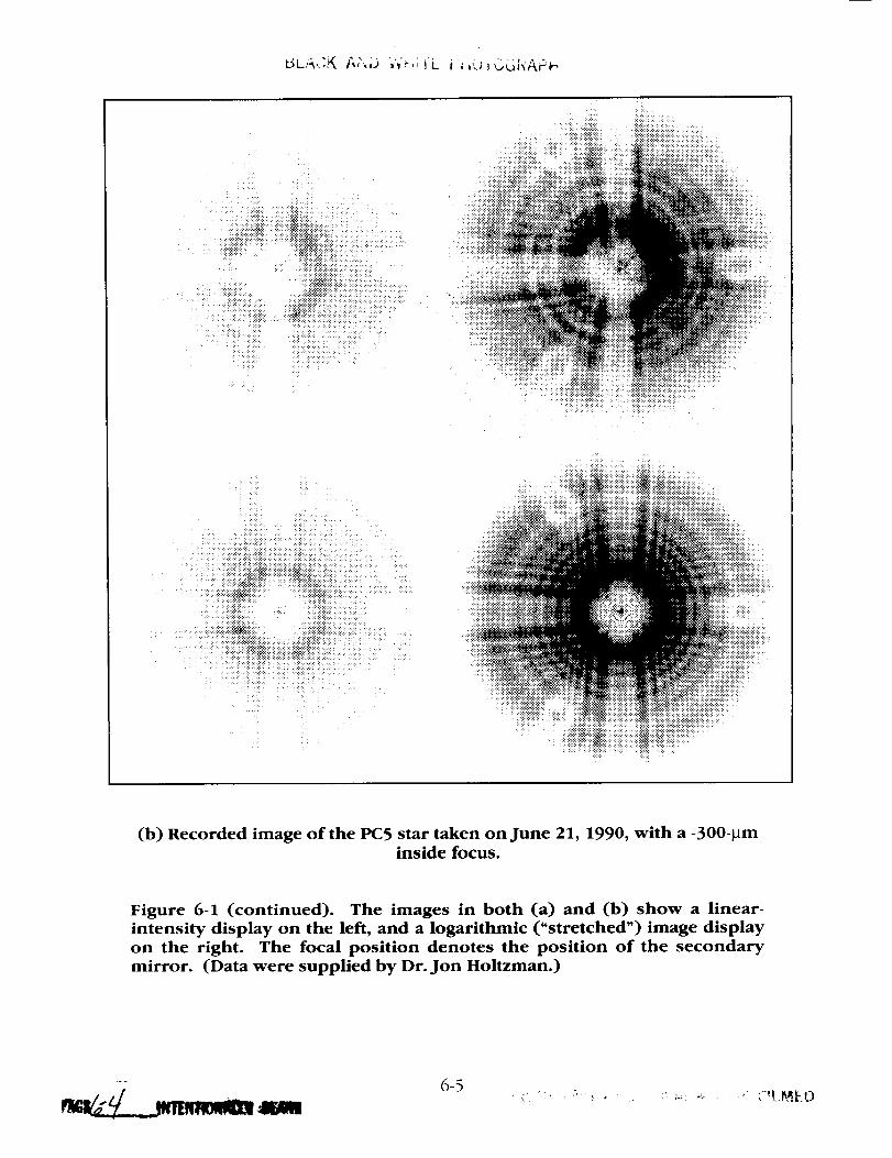
(b) Recorded image of the PC5 star taken on June 21, 1990, with a -300-_minside focus.
Figure 6-1 (continued). The images in both (a) and (b) show a linear-
intensity display on the left, and a logarithmic ("stretched") image display
on the right. The focal position denotes the position of the secondary
mirror. (Data were supplied by Dr. Jon Holtzman.)
6-5


A fault-tree analysis of the RNC and the manufacturing data indicated three
reasonable possibilities for the error:
(1) The field lens was inserted backward.
(2) The index of refraction of the field lens was incorrect (i.e., the
wrong glass was used).
(3) The optical elements were incorrectly spaced (a circumstance that
seemed highly unlikely because of the method used to set the lens
spacings).
It was possible to be so specific because spherical aberration is a symmetric
error and can only be produced by a longitudinal spacing error. A more extensive
analysis to cover other, less viable causes of spherical aberration was halted once
the Board agreed on the cause of the on-orbit spherical aberration.
The Board decided that no tests were to be performed on the null correctors
that might in any way disturb their present condition, because the null correctors
were the only direct links by which to determine the actual shape of the primary
mirror in orbit. This precise shape data would be needed if the telescope were to
be fixed or brought back to the originally specified image quality.
Under this restriction, the RNC could not be moved from its place at the top of
the test tower, nor could it be adjusted or disassembled. By design, the RNC had
access ports in its sides so that it was possible to get at the various optical
elements in order to make the necessary measurements.
The first test performed on the RNC was to insert the INC and take an
interferogram on July 22, 1990. This interferogram was analyzed and compared
with a previous interferogram taken with the INC in place. (This latter
interferogram was found in a notebook of a P-E employee and was dated June 22,
1982.) Comparison of these two interferograms (Figure 6-2) shows virtually
identical' results, clearly indicating the existence of spherical aberration. These INC
interferograms are corroborated by the RvNC interferograms, which also show
spherical aberration (as discussed in Appendix D, Figure D-2). The combination
of these interferograms led the Board to conclude that the CORI/RNC assembly is
now essentially in the same state of operation as it was at the time the final
measurements were made on the primary mirror.
Unverifiable testimony raised the possibility of a waiver having been granted for
an optical spacing error in the INC. During the current investigation, an error in
the design calculations was discovered that produced a small amount of spherical
aberration in the INC. An analysis of the "as-built" INC conducted for the investi-
gation showed that the instrument had an accuracy to better than 0.14 wave.
1_6¢d1___'___ tNTENTIOftAI_II
6-7
(a) 0.4
0.3
c_
0.2LU"E3
(-9 0.1<2_I.--zw
__ 0LJ-
LLI
0
-0.1
-0.2
I ] I I I I I I I t I
B
_
_ //'
//
-/
I 1 I4 5/6 7/8
V tI I I
9/10 11 12/13
6/22/82
- 7/22/90
I I I I J14/15 16/17 18/19 20/21 22
SCHMIDT COEFFICIENTS
(b) 6/22/1 982
I-I III1.| 1111 • I| ill.l.Ni
CgNTOURINT(IqVAL ,, .SVAVELENGTH - 0.63 latcrenol
7/22/90
I-I N,_ HI • it N.l Ill
s. • ., - . .. "..
a-1 ee.-0.N0 _-a_4me,iumc._.s_ _l w-I up|
CONTOUR INt(RVAL • .g_AVELENGTH - @.63 Iqlcrone °
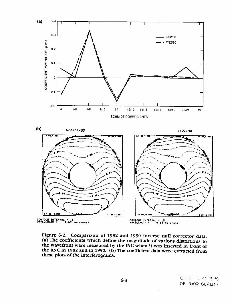
Figure 6-2. Comparison of 1982 and 1990 inverse null corrector data.
(a) The coefficients which define the magnitude of various distortions to
the wavefront were measured by the INC when it was inserted in front ofthe RNC in 1982 and in 1990. (b) The coefficient data were extracted from
these plots of the interferograms.
OF FO0_ QL;ALtT'/

The amount of spherical aberration introduced by the INC error is only a small
amount compared to the amount of spherical aberration actually measured.
The first possibility of error in the RNC involved the field lens. Measurements
were made and it was determined that the field lens was not put into the RNCassembly backwards.
The next test was to measure the effective focal length of the field lens to
verify that the correct material had been used. The actual measurement
determined the magnification of the field lens and verified that the correct glass
had been used. Two spare lenses from the same lot were also measured for figureand focal length, and the measurements confirmed the results on the installed fieldlens.
Since the index was not in error, plans were made to measure the spacing ofthe field lens to the lower mirror in the RNC. This measurement could not be
made as it was originally, because the metering rod used at the time of initial
assembly was too long to fit in the assembled RNC and interferometer unit.
The RNC was designed such that high-precision (l-grin) measurements of the
optical elements could be taken at any time. In the case of the 1.5-m prototype
mirror, the metering rods could be positioned within the RNC to perform the
spacing measurements. For the 2.4-m design, the spacing between the optics was
greater and therefore the metering rods needed to be lengthened. The longest rod
was lengthened in such a way that it could only be inserted in one piece and,consequently, a reverification of this spacing could not be made with this rod
since disassembly of the RNC would be required. In principle, a new rod couldhave been designed in two pieces that would have allowed a remeasurement of
the distance from the field lens to the center of curvature of the lower mirror.
The optical element spacing was measured in 1990 by shining collimated light
up through the field lens using a Zygo interferometer as the source, and by
placing a flat mirror at the focus of the field lens (a distance of about 0.55 m above
the lens). The correct position of the mirror was determined by using the
interferometer to find the best focus (Figure 6-3). The distance from the flat mirror
was then measured down to the vertex of the lower mirror using a fixture in the
mirror hole for a reference. This measurement showed that the field lens was
about 1.3 mm too far from the lower mirror. Both the direction and the magnitude
of the spacing error correctly explained the spherical aberration observed in the
HST image data. The spacings of the other optical elements in the RNC weremeasured and were found to be correct.
6-9

UPPER_
MIRROR
0.55 m
I
~10 m
iIII
iNOTE: THIS DRAWING NOT TO SCALE
_FLAT MIRROR
IIiI
FIELD LENS
iFigure 6-3. The 1990 spacing measurement between the field lens and the
lower mirror of the reflective null corrector, using an optical test.
6-10
In addition to the optical testused to detect the field-lens spacingerror, adirect physical measurementwas made from the field lens to the vertex of thelower mirror (Figure 6-4). A lightweight spacing rod and a new vertex plug weremade. The resultsverified the previously measuredspacingerror to !-'0.1 ram.
More accurate measurements of the displacement error will be done at a later time,
as this information is necessary for an accurate determination of a prescription for
the recovery optics.
When the field lens position error (FLPE) is taken into account and applied in
correcting the data taken with the RNC, it results in a mirror shape that would
account for most of the error observed in the HST images. Also, the
interferograms taken with the RvNC were reprocessed and corrected for the as-
built data available for the RvNC. This independent set of data yields a mirror
shape very close in value to the RNC/FLPE data. These data led the Board to
conclude that the predominant source of error had been found and was caused by
the field lens position error. (See Appendix E for the HST performance based on
the as-built data.)
6-11

LOWER MIRROR
,I],SUPPORT
I # I/
LENS ""/ FIELD LENSSUPPORTPLATE
I
Figure 6-4. The 1990 spacing measurement between the lower mirrorvertex and the field lens of the reflective null corrector,
using a mechanical technique.
6-12

CHA.VrER VII
HOW THE ERROR OCCURRED
A. INTRODUCTION
It has been established that the field lens was approximately 1.3 mm too far
from the lower mirror of the RNC, which was used to figure the primary mirror.
The RNC and its associated interferometer were found in the test chamber, unused
and unchanged since the completion of the HST program. The RNC was
measured in situ, and there is high confidence that the spacing error existed
during the fabrication and test of the HST primary mirror. The cause of the
spacing error, on the other hand, becomes a matter of conjecture, because the
records necessary to reproduce what actually happened were not found. The
scenario given below reproduces the events and provides a rationale of how the
spacing error occurred. This scenario was simulated in the laboratory under the
guidance of the Board and is the most likely cause of the error.
B. METERING ROD MEAS_S
At the beginning of the program to build the 2.4-m Hubble primary mirror, P-E
modified the RNC that had been used in building a 1.5-m mirror prototype. This
modification required adding a new field lens and respacing the optical elements
to create the correct shape for the larger mirror. Figure 7-1 is a schematic of this
RNC, including the positions of the metering rods used to set the optics.
There were three metering rods (labeled A, B, and C) made of Invar, a metal
with a small temperature expansion coefficient. The ends of the metering rods
were rounded and polished because the very precise positioning of the optics in
the RNC used an interferometer, rather than a mechanical measurement. This
procedure involved auto-reflecting a focused beam of light off the end of a rod
and observing an interference pattern from the beam that came back on itself.
Centering the light beam on the rod end was essential for the measurement.
To prevent the metering rod from being misaligned laterally with respect to the
interferometer axis, P-E decided to attach "field caps" to one end of the rod
(Figures 7-2 and 7-3). The field caps were fitted over the rod ends and had a
small aperture in the center to ensure centering of the rod on the beam.
7-1

C ROD~41 cm
FOCUS
UPPERMIRROR
qi
r
A ROD-20 cm
B ROD~58 cm
CENTER OFCURVATURE OFLOWER MIRROR
CENTER OFCURVATURE OFUPPER MIRROR
-21 cm
__l
NOTE: THIS DRAWING NOT TO SCALE
LOWERMIRROR
METERING ROD
/-- PRIMARY
I
Figure 7-1. Position of metering rods used to space optical elements in thereflective null corrector.
7-2

L
7-3
COG)R PHO_OGRAPH
i
o
1,1
ol,i
°,'_
i
o
o
*,NI_,


Figure 7-3. Metering rod in position between the field lens and the center
of curvature of the lower mirror in the reflective null corrector.
r
_aa _ tmam_m
7-5 ORIGINAL PA_7
COLOR PHOTOGRAPH


The top surface of the field cap was covered with nonreflecting material; however,
some of this material had, apparently inadvertently, broken away from a small area
around the field cap aperture. It appears that the operator obtained reflection
from the field cap where the nonreflecting material was absent, rather than the rod
end, causing the 1.3-mm misspacing. A test performed in 1990 with the
equipment showed that it was quite easy, even probable, to make this error with
the configuration used. Figure 7-4 indicates how the displacement error occurred
by reflecting light off the field cap, rather than the rod end, as designed. Figure
7-5 is a photograph of the field cap and shows the specular region around the
aperture. (In this photograph, the broken-away coating appears darker than the
surrounding region.)
With one end of the metering rod presumably located at the center of
curvature of the lower RNC mirror, the field lens was then brought up to the end
of rod B, but there was no adjustment left in the screws used for this positioning.
More adjustment room was made by inserting spacers between the field lens and
the lower mirror mounting plate. The adjustment mechanism was found not to be
staked. Staking, i.e., securing the mechanism to prevent inadvertent movement,
was a specified procedure. The final location of the field lens was then set with
the addition of the spacers. As a result, the field lens was about 1.3 mm too far
from its correct position relative to the lower mirror.
7-7
<.__, __ ,
7_-"1

INTERFEROMETER OBJECTIVE
LENS
DISPLACEMENT OF METERING \ t /
\/I I t
1.3 mm _J/v
FIELD CAP
_METERING ROD _/_
AS DESIGNED ACTUAL
Figure 7-4. Displacement due to the interferometer focusing on the field
cap instead of the metering rod.
7-8

ANTIREFLECTIVECOATING
BROKEN AWAYANTIREFLECTIVECOATING
I [I IImm 10
I2O
Figure 7-5. Top view of the field cap, showing the aperture and the area
where the antireflective coating had broken away.
1- ", "_ _ 7,,') ' _ " "_ " _-'_ _ _ i
7-9


CHAPTER VIII
QUAIXI'Y ASSURANCE OBSERVATIONS
The error in the HST has brought the role of quality assurance (QA) into
question, since the problem remained undiscovered before launch. From an
examination of the evidence, it is clear that there were specific QA requirements in
the contract for the building of the OTA and that an "OTA Product Assurance Plan"
was written and released in 1978 by Perkin-Elmer. Less clear are the contract's
data retention requirements and to which aspects of the P-E hardware they
applied. While the OTA Product Assurance Plan did not specifically refer to
testing of the RNC, the plan did set forth detailed requirements in regard to
validation and engineering sign-off that would have ensured that the RNC would
be adequately designed and tested. If this QA plan had been rigorously applied, it
is probable that the HST error would never have occurred. At the very least, it
would have been much easier to reconstruct what had happened if a complete
record of the fabrication of the test equipment and mirrors had been retained.
Review of the existing documentation indicates that the QA function relating to
the metrology of the primary mirror was inadequately staffed. Defense Contract
Administration Services (DCAS), now Defense Contract Management Command
(DCMC), personnel were not added to the Project's staff until after the primary
mirror was completed. Both the MSFC and the P-E QA personnel were excluded
from key areas and at critical times. This decision was made by P-E engineering
management with the concurrence of the MSFC Project Office. The result of this
decision was that an informed and independent evaluation of the assembly and
manufacturing area was not done.
In addition, the P-E QA personnel reported to the OTA Project Manager rather
than to someone independent of immediate Project pressures. This may also
explain why QA personnel were apparently denied access to metrology areas
where they could have hindered the data-taking and analysis process.
At the time of the primary mirror's polishing and testing, the quality reviews
and audits conducted according to the QA Plan did not raise technical issues about
the shortcomings of the test procedures prior to their implementation. The
procedures did not provide criteria for the correct results of testing and thus did
not provide guidance toward identifying unexpected out-of-limits behavior of the
optical tests. In most cases, the expected results of the optical tests were not
specified, and inexperienced personnel were not able to distinguish the presence
of an unacceptable behavior of the tests. There was also no criterion given for the
required experience of the observer approving passage of a milestone on the basis
8-1

of test results. In hindsight, and with the knowledge there was a problem with themirror, it is easy to see that various technical issuesabout the testprocedures, suchasthe lack both of independent testsand of any correlation of the resultsofrelated tests,should have been questioned.
When the primary mirror was transferred from P-EWilton to P-EDanbury atthe beginning of PhaseII of the contract, a DoD-c/assifiedproject was ongoing atthe Danbury site. Initially, DoD imposed a restriction on the number of NASApersonnel who had accessto the Danbury faciliW, However, this restriction was
seen by the MSFC Project Manager as being too constraining and then was
subsequently renegotiated with DoD. Unlimited access by NASA personnel was
allowed after that time. The DoD project did not prohibit NASA QA from
adequately monitoring the P°E activi W.
The Optical Operations Division of P-E imposed its own access limitations to
the Danbury metrology area where the RNC and INC were assembled. This area
was secured by a cipher lock door, and only metrology engineers from the Wilton
facili W were allowed access. QA personnel from both NASA and P-E were not
informed that this test equipment was being assembled and were aware of its
existence only after the RNC assembly was moved to the OTA test chamber. No
formal manufacturing-process paperwork on this activi W was filed; consequently,
the QA organization did not become involved.
Other evidence that QA did not play as full a role as outlined in the QA Plan is
shown by the lack of, or even callouts for, QA signatures on several procedures
relating to the primary mirror metrology. Similarly, it is perhaps because the P-E
QA personnel reported through the Project management that there is no written
evidence that QA ever protested being denied access either to the primary mirror
test area during the actual testing or to the area where the data were being
analyzed.
Finally, there is no evidence of QA records calling into question the
discrepancies in the actual test data that seem so obvious in hindsight. No
mention has been found in any records that the RNC could not be recalibrated in
the same manner as when it was first assembled, or that the RNC/INC test showed
spherical aberration when it should not have. Neither was any mention made that
the vertex radius test with the RvNC showed spherical aberration in the finished
primary mirror when it should have shown none. There was no formal and
centralized information management system to retain and categorize the
voluminous data that defined the HST.
The documentation describing the addition of the spacers under the field lens
to achieve the apparent proper spacing of this element was never filed or has
8-2

been lost in the intervening 10years. This can be understood in part since the QA
organization was not involved in this activity. A reference was made during the
testimony that a Material Review Board was held on the spacer issue, but no
documentation was found.
What is clear from the error that occurred, and the evidence found, is that QA
has a significant role to play in the avoidance of similar problems on future
programs. For this to happen, however, the role of QA must be understood and
seen as a positive factor by top management. QA organizations must be
adequately staffed by fully qualified individuals, and these people must be given
free access to all aspects of the project, from conceptualization through final
delivery. They should have clear authority to stop work on projects where there
are unresolved quality issues. They should also have an independent reporting
path to top management to avoid the undue influences and schedule pressures
being imposed by the program or the engineering organizations.
Further, thorough and well-cataloged documentation of all these aspects of the
project must be maintained by the contractor and/or NASA for the duration of the
mission. To do otherwise will make recovery of salvageable missions improbable
or impossible.
Additional quality assurance information on the HST can be found in an
extensive report, SRM&QA Observations and Lessons Learned, by George A.
Rodney, Associate Administrator, Office of Safety and Mission Quality, National
Aeronautics and Space Administration, dated October 1990.
8-3


CHAtrrER IX
THE ERROR WAS NOT DETECTED PRIOR TO FLIGHT
The explanations for why the HST error was not detected before launch can be
separated into two categories: factual and judgmental. Based on the test plan that
was in place at the time of the fabrication of the HST mirrors, the factual issues
presented in this Chapter were events that should have warned the Project
personnel of the existence of a problem. The judgmental issues that follow are
conclusions based on the Board's own expertise.
A. FACTUAL STATEMENTS
1. Complete reliance was placed on the reflective null corrector (RNC) to
determine the shape of the primary mirror. It was determined that the RNC would
be certified only by accurate measurement of the elements and the spacings.
Although test philosophy placed great emphasis on "certification" of the RNC, the
Board could not find documentation that the RNC was certified. In spite of the
total reliance on the RNC, no independent measurements were made of the
optical-element spacings of the RNC to verify the values. Although the RNC was
designed so that spacings could be rechecked without disassembly, the actual
implementation did not permit such measurements, and no remeasurement of
spacings was made after'initial assembly.
2. The erroneous measurement of the spacing of the field lens of the RNC
led to the need to install spacers to increase the separation of the field lens from
the lower mirror. The bolts securing the field-lens basket were not staked,
suggesting a lack of quality surveillance, since securing bolts was a common and
easily observable inspection to conduct. These anomalies should have led to a
Material Review Board (MRB) approval document and a thorough consideration of
the cause. Although the NASA representative recalls approving such an MRB, no
documentation was found.
3. After the RNC was assembled in the laboratory, an INC was set up below
the ILNC. The INC was intended to simulate a perfect mirror below the RNC so
that any errors in the null corrector could be detected. The interferograms taken
when using the INC to align the RNC/CORI indicated a spherical aberration pattern
(see Figure D-3). The full RNC/CORI assembly was then moved to the top of the
optical telescope assembly test chamber, and each time the primary mirror was
tested the INC was used to check the alignment of the setup. As before, the same
spherical aberration distortion was evident in the fringes. These aberration fringes
9-1

could not be aligned out and were incorrectly attributed to the spacingerrors inthe lens systemof the INC. Perkin-Elmer'sOptical Operation Division believedthat the INC was not reliable when, in fact, it was quite accurateenough to detectthe grosserror, and indeed did so.
4. The vertex radius measurementtaken by the refractivenull corrector(RvNC) indicated the presenceof spherical aberration (see Figure D-2). Thisinformation was dismissed,as it was in the casefor the INC, becausethe RvNCwas believed to be lessprecise than the RNCand therefore not reliable. It hasbeen determined that the RvNCwas easilyaccurateenough to detect the sphericalaberration that existed, and its reliability should not have been discounted.
5. There were two other occasions when a careful analysis of the data might
have revealed the problem:
a. The primary mirror was ground and polished to an approximate
shape, about 1 wavelength rms, using the RvNC for the test. This
took place at Perkin-Elmer's facility in Wilton, Connecticut. The
mirror was then transferred to P-E's Danbury facility, where the RNC
was the test instrument for final polishing. At the time of transfer,
the interferograms obtained with the RvNC were compared with
those obtained from the RNC, and the discrepancy could have been
noted. However, the data and the circumstances of transfer are
unclear, and the requirements for transfer appeared to be adequately
met; therefore no concern was noted.
b. After the assembly of the OTA, tests were performed to assure
proper focus position. Those tests were made with a 0.36-m
telescope (subaperture test), and careful analysis of the data might
have revealed the problem. However, the data were complicated by
gravity sag because the OTA was mounted horizontally, and only the
focus position was verified.
6. A range of feasible tests to verify the shape of the primary mirror were
considered, but not carried Out. Finally, no end-to-end tests were planned or
implemented to verify the performance of the OTA.
B. JUDGMENTAL STATEMENTS
The following judgements are offered with the recognition that there were
many distractions and crises during this period---cost, schedule, threat of
cancellation, mirror contamination, possibility of mirror distortion caused by
9-2

mount, etc. Nevertheless,the flaw occurred and, as can now be seen,these arefactors that bear on that occurrence.
1. The proposal of P-E,accepted by NASA, to rely entirely on the RNC
should have alerted knowledgeable people in P-E and NASA that special attention
was required to certify the RNC; to the need for independent validation of the RNC
and/or the primary mirror; and to the need to examine and review the test data for
any indications of inconsistency. A project test plan that considered the various
measurements, the possibilities of error in each, and the feasibili W of independent
checks should have been prepared by the implementing organization and
externally reviewed.
2. The conclusion by P-E, accepted by NASA, that the RNC was the only
device that would yield an accuracy of 0.01 wave rms at 632.8 nm led P-E to fail to
consider any independent measurement which would yield less accuracy. In fact,
such independent data were obtained incidental to other measurements and were
rationalized away due to this mindset.
3. The HST development program was complex and challenging and there
were many issues demanding management attention; the primary mirror was only
one of these. Although the telescope was recognized as a particular challenge,
with a primary mirror requiring unprecedented performance, there was a
surprising lack of participation by optical experts with experience in the
manufacture of large telescopes during the fabrication phase. The NASA Project
management did not have the necessary expertise to critically monitor the optical
activities of the program and to probe deeply enough into the adequacy and
competence of the review process that was established to guard against technical
errors. The record of reviews reveals no sensitivity to in-process data and no
questioning of the test method.
4. The NASA Scientific Advisory Group did not have the depth of experience
and skill to critically monitor the fabrication and test results of a large aspheric
mirror. However, this Group should have recognized the criticality of the figure of
the primary mirror and the fragility of the metrology approach, and these concerns
should have impelled them to penetrate the process and ask for validation.
5. A highly competitive environment existed between Perkin-Elmer and the
Eastman Kodak subcontractor. Although the manufacturing process and the
method of measurement for the backup primary mirror were reviewed and
approved by P-E, there was limited additional technical exchange of experience.
NASA did not utilize the opportunity offered by this directed subcontract to
validate, and gain confidence in, the P-E approach to the primary mirror
manufacture.
9-3

6. Perkin-Elmer line managementdid not review or supervise their OpticalOperations Division adequately. In fact, the managementstructure provided astrong block againstcommunication between the people actually doing the joband higher level expertsboth within and outside of P-E.
7. The P-ETechnicalAdvisory Group did not probe at all deeply into theoptical manufacturing processesand, although they recognizedthe fragility of themeasuring approach, they did not adequatelyasserttheir concernsor follow upwith data reviews. This is particularly surprising since the memberswere aware ofthe history of manufactureof other Ritchey-Chretientelescopes,where sphericalaberration was known to be a common problem.
8. The most capable optical scientistsat P-Ewere involved closely with theproduction of the 1.5-mdemonstration mirror and the designof the HST mirrorand the test apparatus. However, fabrication of the HSTmirror was theresponsibility of the Optical OperationsDivision of P-E,which did not includeoptical design scientistsand which did not use the skills external to the Divisionwhich were available at Perkin-Elmer.
9. The Optical Operations Division at P-Eoperated in a "closed-door"environment which permitted discrepantdata to be discounted without review.During the testimony, it was indicated that some technical personnel in the OpticalOperations Division were deeply concerned at the time that the discrepant opticaldata might indicate a flaw. There areno indications that theseconcerns wereformally expressedoutside this Division.
10. The quality assurancepeople at P-E,NASA,and DCAS(DefenseContractAdministration Services,now DefenseContractManagementCommand)were notoptical experts and, therefore,were not able to distinguish the presenceofinconsistentdata results from the optical tests. The DCASpeople concentratedmainly on safetyissues.
11. The basic product assurancerequirementsand formal review processeswere procedurally adequateto raise critical issuesin most safety,material, andhandling matters,but not in optical matters.
12. The inability of P-Eto provide the Board with vital archival data on thedesign and manufacture of the primary mirror is an indication of inadequatedocumentation practices,which hampered the Board in determining the source ofthe primary mirror error.
9-4

CHAFI'ER X
LESSONS _D
A. IDENTIFY AND MmGATE RISK
The Project Manager must make a deliberate effort to identify those aspects of
the project where there is a risk of error with serious consequences for the
mission. Upon recognizing the risks the manager must consider those actions
which mitigate that risk.
In this case, the primary mirror fabrication task was identified as particularly
challenging due to the stringent performance requirements. The contractor clearly
specified in the proposal that total reliance would be placed on a single test
instrument and that no optical performance tests would be made at higher levels
of assembly. Therefore, OTA performance would be determined by component
tests and great care in precision assembly. Although NASA accepted this proposal,
the methodology should have alerted NASA management to the fragility of the
process, the possibility of gross error (that is, a mistake in the process), and the
need for continued care and consideration of independent tests.
The history of spherical aberration in the primary mirrors of Ritchey-Chretien
telescopes was known to some of the optical scientists involved, but did not lead
to specific recommendations early in the Project. Late in the Project an advisory
group did call out the risk of gross error and suggested simple tests to check for
such errors. This recommendation was not seriously considered, primarily due to
total lack of concern that such a risk was reasonable, but also in view of cost and
schedule problems.
Several methods of detecting the flaw were inherent in the testing, but Project
management did not recognize the value of or need for independent tests. Project
management was concerned about the performance specifications and directed a
subcontract to Eastman Kodak Company for an alternate primary mirror. The
Eastman Kodak mirror was fabricated and tested using quite different techniques.
The mirror or the instrumentation could also have served as cross-checks for gross
error. Such error checks were not made, again due to total lack of concern about
the possibility of gross error. Project management failed to identify a significant
risk and therefore failed to consider mitigating actions. A formal discipline such as
fault-tree analysis might have assisted the manager in directing his attention to this
risk.
10-1

B. MAINTAIN GOOD COMMUNICATION WITHIN THE PROJECT
While proper delegation of responsibility and authori W is important, this
delegation must not restrict communication such that problems are not subject to
review. In this case, the Optical Operations Division of P-E was allowed to
operate in an artisan, closed-door mode. The impermeabiliw of this Division
seems astounding. The optical designers at P-E did not learn how their designs
were being implemented; e.g., if the designer of the null correctors had been
following their use, the data from the INC and the RvNC likely would not have
been discounted. The data indicating the flaw was of great concern to some
members of the division. Testimony indicates that their concerns were addressed
at the level of the head of metrology and the division manager, but were not
discussed outside the division at all. There were individuals who were not
satisfied by the decision to rely only on the RNC data and remained deeply
concerned. Their concerns and the data which caused them did not seem to come
to the attention of anyone external to the division. P-E management should have
been sensitive and open to these concerns. The P-E Technical Advisory Group
should have found out what was going on in the Division and insisted on
reviewing in-process data. NASA Project management should have been aware
that communications were failing with the Optical Operations Division.
Contributing to poor communications was an apparent philosophy at MSFC at
the time to resolve issues at the lowest possible level and to consider problems
that surfaced at reviews to be indications of bad management.
A culture must be developed in any project which encourages concerns to be
expressed and which ensures that those concerns which deal with a potential risk
to the mission cannot be disposed without appropriate review, a review which
includes NASA project management.
C. UNDERSTAND ACCURACY OF CRITICAL MEASUREMENTS
The project manager must understand the accuracy of critical measurements.
P-E concluded, based on design considerations, that the RNC was the only test
device which could achieve the required precision. They stated that its
performance could not be determined by optical test but would be determined by
component and assembly measurements which could be made in situ.
P-E engineers regarded the RNC as "certified" and the INC and RvNC as
"uncertified." The terms were not defined, and "certification" was not
documented. P-E discounted evidence of spherical aberration from INC and RvNC
measurements on the basis of "uncertified" status. In fact, the Board reviewed a
recent as-built error analysis of both devices. The review showed the RvNC to be
10-2

accurate to 0.02wave rms and the INC to 0.14wave rms. This indicates that theINC is a factor of three more accuratethan the error observed in the INC/RNCinterferograms. While in-processdatawere not subject to external review, whichis another lesson, the methodology of test instrument use was reviewed by P-Eand NASAmanagement. This review could and should have questioned thejudgment not to use the INC or the RvNCasindependent checksof the accuracy
of the RNC even though the precision was not to specification. Project
management must understand critical tests and measurement.
In addition, the project management must seriously consider the classification
of test equipment that directly impacts the flight hardware. The RNC was classified
as standard test equipment, which means that the RNC was not subject to the
rigorous documentation and review requirements demanded of items classifed as
flight hardware equipment. Under the contract, there were no Government
regulations requiring that records for the RNC be maintained. Considering the
importance placed on the RNC in the test program, management should have
upgraded the level of classification of this equipment.
Key decisions, test results, and changes in plans and procedures must be
adequately documented. In preparing such documentation, individuals are forced
to review and explain inconsistencies in the test data. This also provides a
communication link to those individ_aals who are responsible for overseeing the
project.
D. ENSURE C_ ASSIGNMENT OF RESPONSIBILITY
Project managers must ensure clear assignment of responsibility to QA and
Engineering. NASA QA personnel were not optical system experts. The Project
relied upon P-E Engineering to establish test and fabrication procedures, and P-E
or NASA QA generally verified that Engineering approved and certified
accomplishment of procedures. However, at times, NASA management seemed to
rely on QA to verify the adequacy of procedures and the fact that they were
satisfactorily accomplished. This lack of clarity apparently led to incomplete
documentation and may have contributed to faulty procedures. The project
manager must know what QA can and cannot do, and when it is necessary to rely
on engineering for verifying its own procedures, management should be alert to
the need for independent checks.
Quality assurance, to be truly effective, must have an independent reporting
path to top management.
10-3

E. REMEMBER THE MISSION DURING CRISIS
There will be a period of crisis in cost or schedule during most challenging
projects. The project manager must be especially careful during such periods that
the project does not become distracted and fail to give proper consideration to
prudent action. At one point in the fabrication cycle of the primary mirror, an
urgent recorfimendation for independent tests to check for gross error entered the
system, but was apparently not acted upon. Again, at the completion of mirror
polishing, the final review of data for a final report was abandoned and the team
reassigned as a cost-cutting measure.
F. MAINTAIN RIGOROUS DOCUMENTATION
The project manager should ensure that documentation covering design,
development, fabrication, and testing is rigorously prepared, indexed, and
maintained. Because quality, at a minimum, consists in meeting requirements, it is
not possible to determine whether the necessary quality is being achieved if the
requirements are not set forth in sufficient detail and maintained in retrievable
archival form. Adequate documentation also helps maintain a disciplined
approach to fabrication and testing processes, especially with so complicated a
project as the HST.
10-4

GLOSSARY
arcsec (arcsecond)
astigmatism
axial
A wedge of angle, 1/3600th of one degree, in the 360-degreesphere that makes up the sky. An arcminute is 60 seconds;a degree is 60 minutes.
A defect of curvature that prevents sharp focusing anddegrades the quality of an image.
Along the optical axis of a telescope.
baffle Structure that obstructs stray light from the incoming image(see Figure 2-1).
C&DH
Cassegrain
coma aberration
concave
convex
CORI
command and data handling
A type of two-mirror telescope that reflects or "folds"incoming light.
A type of aberration where the rays from a point source donot meet at one focus, but rather spread into a comet-shaped area (see Figure C-2).
A mirror surface that bends outward to expand an image.
A mirror surface that bends inward to concentrate animage.
Coaxial Reference Interferometer
DCAS
DCMC
DoD
Defense Contract Administration Services, now DCMC
Defense Contract Management Command, formerly DCAS
Department of Defense
Einstein
Observatory
EK
The High-Energy Astronomy Observatory (HEAO-2)
managed by Marshall Space Flight Center.
Eastman Kodak Company
FGS
figure
first light
fine guidance sensors
The shape of an optical surface.
When an instrument's shutter is first opened and lightenters the instrument.
11-1

FLPE
FOC
focal plane
fringe pattern
field lens position error
Faint Object Camera
The geometric plane where incoming light is focused by
the telescope.
The bright and dark alternating intensity pattern in an
interferogram (see Figure D-l).
GSFC Goddard Space Flight Center
HDOS
Hindle test
HST
hyperboloidal
Hughes Danbury Optical Systems, Inc.
An arrangement for testing a convex hyperboloid by
retroreflection; used to shape the Hubble Space
Telescope's secondary mirror.
Hubble Space Telescope
A slightly deeper curve, mathematically, than a parabola;
the shape of the Hubble Space Telescope's primarymirror.
image plane
INC
interferogram
The geometric plane in the telescope where the image isreconstructed.
inverse null corrector
A photograph of an interfering light pattern; used to test
the figures of the Hubble Space Telescope's mirrors.
JPL Jet Propulsion Laboratory
knife-edge test A simple, qualitative test to measure an optical figure.
LMSC Lockheed Missiles and Space Company, Inc.
MRB
MSFC
Material Review Board
Marshall Space Flight Center
NASA National Aeronautics and Space Administration
11-2

OOD
ORA
OTA
Optical Operations Division (at the Perkin-ElmerCorporation)
Optical Research Associates
Optical Telescope Assembly
PA
PCS
P-E
product assurance
pointing control system
Perkin-Elmer Corporation, now HDOS
QA
QC
quality assurance
quality control
radial
R-C
rms
RNC
RvNC
Perpendicular to the optical axis of a telescope; forexample, instruments placed at a 90-degree angle from the
optical axis of the Hubble Space Telescope.
Ritchey-ChretienmA type of Cassegrain telescope where
both the primary and secondary mirrors are hyperboloidal
to correct for image aberrations; the Hubble Space
Telescope's Optical Telescope Assembly (see Figure 2-1).
root mean square
reflective null corrector
refractive null corrector
SAIC
spectrum
SRM&QA
Science Applications International Corporation
The wavelength range of light in an image.
safety, reliability, maintainability, and quality assurance
TDRSS Tracking and Data Relay Satellite System
vertex radius test A comparative measurement of the primary mirror's radiusof curvature at its center.
waveffont The surface composed of all the points just reached by abundle of light rays from a source.
11-3
wavelength(wave)
WF/PC
WFS
The distancein a wave from any one point to the next pointof corresponding phase (for example, the distance fromone wave crestto the next is one wavelength).
Wide Field/Planetary Camera
wavefront sensors
11-4

APPENDIX A
CHARTER AND MEMBERSHIP
OF THE BOARD


DJA.SANationalAeronau_cs antS_ace Ac_minis_ratian
Washington. D.C.20-.'46
JUL 2
TO:
FKOM:
SU3_CT:
Direc=or, JeZ Propulsion Laboratory
ATTN: Dr. Law Allen
$/Associaze A_inis_ra_or for Space Science and
App!ica_icns
Esuablisi%_en: of Hu_le Space _ --Te.es..p_ Cp:ica!
Systems 5¢a=d of _nves_iga_ion
Xn accordance wi¢h the Hubble Space Telescope (KST)
Conulngency Plan date_ 2/15/%0, _he Office of Space Science
and Applications is esUab!ishlng a "Hubble Space Telescope
Optical Systems _oard of _nves_iga_icn." I a_ hereby
appointing you :c serve as _he Chairman of _ha: Board. i_ is
our in_enu to establish a board whose members, primarily from
outside NASA, are world renowned in _he figld of optical
systems and spacecraft _ali_y control. This Board of
InvesZiga_ion will be a wo=klng group charged UO review,
analyze, and ev_!ua_e the fac_s aad ci:c%u_s_ances :egardin_
the manufacture, _eveiopmen_ and _esting of _he Optical
Telescope Assembly.
Your charge as Board Chai_-'man is _o determine how and when the
p_oblems £_ the Optical Telescope Assembly (OTA] occurred,
thereby leading tO _h_ observed sphe:ical abe:ration, and how
this aberration could go undetected pEio= Uo launch. The
group will repot', the =esul_$ of _hei_ evalua_£on to _he
Associate A_.miniscrauor for Space Science and)_p!i¢auions.
This group is no_ es_llshed _c render, advise, or make
recommendations.
This operational w_=king group is an exception _o the
provisions of _he Federal A_vlso_ Committee Ac_. There is no
re¢!uiremenU for public noSice as _o meetings or _o have such
meetings open uo _he public.
.h. immedla¢e poin_ of contact a_ NASA Headquarters for
infoxma_ion, ass!stance and suppo_-_ will be _he Director,
Aszrophysics Division, D=. Charles Pellerin. He can be
reac_ed au 202/453-1437 [office) O_ 202/488-1423 residence).
A-I OR_CIP,!_L PACE IS
OF POOP_ QUALITY

Again, I wan_ to convey my appreciation for you= willingnessto chair this board. You= laac_8_ship of. thla group will be
insurumenta! in assu:in9 a systematic review of the HST
optical Systems.
L. A. Fisk
CONCURRENCE:
Associate Adm_/nls_=ator for
Safety and Mission Quality
A/AcLm Truly
AD/M_. Thompson
G/M_. Trankel
S/Mr. Diaz
Mr. Alexander
Mr. Rhome
Ms. $c._moll
S_S/Ms. Phillips
SZ/D=. Pellerin
L/Mr. Kress
P/Mr. Sheehan
X/Mr. Pe_ersen
Q/M:. Rodney
• '_? _;
A-2

MEMBERS OF THE BOARD OF INVESTIGATION
Dr. Lew Allen, Chairman
Director, Jet Propulsion LaboratoryPasadena, California
Dr. Roger Angel
Professor of Astronomy, Steward Observatory
University of Arizona
Tucson, Arizona
Mr. John D. Mangus
Head, Optics Branch, Space Technology DivisionNASA/Goddard Space Flight Center
Greenbelt, Maryland
Mr. George A. Rodney
Associate Administrator for Safety and Mission Quality, NASA HeadquartersWashington, DC
Professor Robert R. Shannon
Director, Optical Sciences Center
University of Arizona
Tucson, Arizona
Mr. Charles P. Spoelhof
Vice President (Retired), Eastman Kodak CompanyPittsford, New York
A-3


APPENDIX B
SUMMARY OF PROCEEDINGS
HL_BLE SPACE TELESCOPE
OPTICAL SYSTEMS BOARD OF INVESTIGATION


INTRODUCTION
The Hubble Space Telescope Optical Systems Board of Investigation was
formed in early July 1990 at the request of Dr. Lennard Fisk, Associate
Administrator for Space Science and Applications, NASA. Dr. Lew Allen, Director
of the Jet Propulsion Laboratory, was appointed Chairman of the Board. The
purpose of the Board was to review, analyze, and evaluate the facts and
circumstances regarding the manufacture, development, and testing of the Hubble
Space Telescope Optical Telescope Assembly (OTA). The Board was not open to
the public or press. All of the relevant documents and hardware at the OTA
manufacturer, Hughes Danbury Optical Systems, Inc. (HDOS) were impounded
soon after discovery of the flaw, in preparation for the investigation.
The objective of the investigation was to identify, to the degree possible, the
causes behind an apparent manufacturing flaw in one of the mirrors in the OTA,
and to determine why the flaw, which impacts the focusing ability of the OTA,
was not discovered prior to the launch of the spacecraft. Parallel efforts aimed at
making a definite determination of the nature and location of the flaw through
analysis of data retrieved from the orbiting HST were ongoing at the onset of this
investigation.
Serving the Board in an advisory capacity were Ms. Sarah Keegan, NASA Public
Affairs Officer, and Mr. Gary Tesch, NASA Deputy General Counsel. Serving as
staff to Dr. Lew Allen were Drs. Macgregor Reid and James Breckinridge, and, at
the fourth meeting, Dr. Katherine Dumas, of the Jet Propulsion Laboratory. The
Technical Recorder was Mr. Christopher Thompson of Science Applications
International Corporation (SAIC). Representing Dr. Fisk at the Board meetings was
Dr. Charles PeIlerin, Director of the Astrophysics Division in NASA's Office of
Space Science and Applications. All of the non-NASA employees on and serving
the Board were sworn in as Special Government Employees in order to bind them
to Government regulations regarding conflicts of interest and disclosure of
proprietary data.
A full list of participants in each Board meeting follows the summary of that
meeting.
B-1

FIRST MEETING: JULY 5-6, 1990
vrrRo CORPORATION
WASHINGTON, DC
A. SUMMARY
The first meeting of the Board took place July 5--6, 1990, in a conference room
in the offices of the Vitro Corporation at 400 Virginia Avenue, S.W., in Washington,
DC. Dr. Roger Angel was unable to attend this meeting.
Dr. Fisk convened the Board on the afternoon of July 5 with a word of thanks
and a reminder of the importance of the task that lay ahead. He charged the
Board with determining the technical cause of the spherical aberration in the HST
OTA and the reason why the aberration was not discovered prior to flight. He
suggested that the Board look primarily at technical issues, noting that the period
during which the mirrors were manufactured and integrated was turbulent for the
HST program, with schedule and budget issues leading to a major reorganization,
but that this history should only be considered to the extent that the Board found
that it had an impact on the specific technical issue at hand. Dr. Fisk stated that
he wanted a definite answer, rather than a fast one, and that the Board should do
whatever it had to in order to uncover the cause of the problem.
Dr. Fisk also noted that there was great interest in the HST problems both in
Congress and in the press. He stated that NASA would not direct any Board
member not to speak to the press, but reminded them that it would be
inappropriate to comment on the findings of the investigation until it is complete.
Dr. Fisk also stated that the Board members should not release any of the
documentation of the Board themselves, since the documentation would be
released through formal NASA channels.
The first meeting of the Board focused on presentations arranged by the HST
Project Office at Marshall Space Flight Center (MSFC). These presentations, some
of which were provided by HDOS HST Project personnel, were essentially
background and tutorials on the manufacturing and testing of the mirrors for the
HST OTA at HDOS (then the Perkin-Elmer Corporation), in Danbury and Wilton,
Connecticut. Based on information gathered during these presentations, and on
input the Board received from the HST Independent Optical Review Panel
regarding the ongoing analysis of on-orbit HST data relevant to the aberration
(included as Attachment 1), the Board formed an initial plan for the investigation.
This plan included document analysis, hardware testing, and personnel interviews.
The Board concluded the first meeting with an agreement regarding the release of
B-2
impounded materials for the purpose of beginning a supervised investigation ofthe HST documentsand testequipment at HDOS.
B. PARTICIPANTS
All members of the Board were present, with the exception of Dr. Roger Angel,
who was unable to attend either day of the meeting. Also in attendance:
NASA Headquarters
Mr. Douglas R. Broome
Mr. T. Jens FeeleyDr. Lennard Fisk
Ms. Sarah Keegan
Dr. Charles Pellerin
Ms. Angela Phillips
Mr. Gary Tesch
NASA/MSFC
Mr. Daniel Johnston
Mr. Charles O. Jones
Mr. Fred S. Wojtalik
Hughes Danbury Optical Systems
Ms. Kathleen Beres
Dr. Terence Facey
Mr. William S. Raiford
Mr. John D. Rehnberg
Dr. John C. Rich
Staff to the Board
Dr. James Breckinridge, Jet Propulsion Laboratory (JPL)
Dr. Macgregor S. Reid, JPL
Mr. Christopher J. Thompson, Science Applications International
Corporation (SAIC) (Technical Recorder)
B-3
SECOND MEETING: JULY 25-26, 1990
HUGHES DANBURY OPTICAL SYSTEMS
DANBURY, CONNECTICL_
A. SUMMARY
The second meeting of the Board took place on July 25-26 at the offices of
Hughes Danbury Optical Systems, Inc. in Danbury, Connecticut. The full Board
was in attendance and now included, as an observer, Dr. Robin Laurance of the
European Space Agency.
In the interim since the first meeting, a controlled easement of the impounding
of documents and hardware at HDOS had taken place, as authorized by the Board.
Under the supervision of NASA and the Defense Contract Management Command
in Bridgeport, Connecticut, a review of HST documentation and test equipment at
HDOS was also undertaken. Also since the f'u'st meeting, the Board appointed
Mr. Robert E. Parks, an independent optics consultant, to serve as its full-time, on-
site representative. Mr. Parks participated in data review and test planning at
HDOS and was available to the Board as needed. The Board members were in
regular communication with one another and with Mr. Parks during this time.
Each received pertinent documents and plans for review via datafax as they
became available.
The meeting comprised status reports on work plan elements, reports on
specific studies requested by the Board, and interviews with key former and
current HDOS HST Project employees. The employees interviewed are listed
below. As requested by the Board, HDOS presented a plan for characterizing the
special test equipment known as null correctors used in manufacturing the HST
primary mirror. HDOS also presented a status report on sensitivity analyses being
performed on the test regimes and equipment used in characterizing the primary
and secondary mirrors. These analyses, when complete, would provide
mathematically feasible sources of the magnitude of spherical aberration observed
in the HST imagery. The Board also reviewed options for detailed testing of a
backup secondary mirror manufactured at the same time and according to the
same specifications as the secondary HST mirror now on orbit. Finally, at the
request of the Board, the HDOS HST Chief Scientist made a presentation on a
focus test, using a 0.36-m collimator, that was performed several times on the OTA
before and after it was shipped to Lockheed Missiles and Space Company for
integration.
B--4

The interviews of current and former HDOS HSTProiect personnel were donein two phases. The first phase, during which only the Board, its staff, and the
interviewees were present: was a group interview on the manufacturing and
testing of the primary and secondary mirrors. This phase centered on the two
individuals primarily responsible for these activities, but all of the interviewees
were able to amplify and offer information as they saw fit. There was substantial
discussion of the design of the null correctors (a refractive null corrector that was
used for checking the coarse figure of the primary mirror prior to polishing, and a
reflective null corrector that was used for precise measurement of the figure of the
mirror during and after polishing) and how the null corrector measurement data,
known as interferograms, were analyzed. The second phase of interviews was
conducted by the Board members alone, questioning each individual one at a time
in closed session. The technician who used the reflective null corrector assembly
on the primary mirror, still an HDOS employee, also met with the Board and
explained the procedure in open session on the second day.
Also during the second meeting, the Board toured the HDOS integration and
test area where the primary mirror was polished and analyzed. The Board was
able to visually inspect the exterior of the reflective null corrector assembly in the
test tower, where it has remained unused since the last testing of the primary
mirror in 1982.
The second meeting concluded with agreement for HDOS to conduct
supervised, noninvasive visual inspection of the primary mirror test equipment, for
HDOS to continue with the test equipment sensitivity analysis, and for HDOS to
further model the tests they proposed for characterizing the null correctors. The
Board decided to postpone the authorizing tests of the backup secondary mirror.
B. PARTICIPANTS
All members of the Board were present, including, as an observer, Dr. Robin
Laurance of the European Space Agency. Also in attendance:
NASA Headquarters
Ms. Sarah Keegan
Dr. Charles Pellerin
Mr. Gary Tesch
B-5

NASA/MSFC
Mr. Larry Hill (26th only)
Mr. John Humphreys
Mr. Daniel Johnston
Mr. Joseph Randall
Mr. Fred S. Wojtalik
Defense Contract Management Command (Bridgeport)
Lt. Col. Ken Bohannon, USAF (25th only)
Hughes Danbury Optical Systems
Mr. Robert A. Arnold*
Mr. David Butch
Mr. David Chadwick
Mr. John Cunniff
Mr. R. Thomas Dubos*
Dr. Terence Facey
Mr. William Freeman
Ms. Laurie K. Furey
Mr. Robert Hamed
Mr. Michael Kasseris ° (26th only)
Mr. Frank Krausz
Mr. Malcolm MacFarlane
Mr. Joseph Magner"Mr. David Olson
Mr. John D. Rehnberg
Dr. John C. Rich
Hughes Danbury Optical Systems (former employees)
Mr. Raul E. Casas °
Mr. Louis Montagnino*
Mr. Abe Offner*
Mr. Ronald (Bud) Rigby*
Mr. Charles Robbert"
Mr. Albert F. Slomba °
B-6

Staff to the Board
Dr..lames Breckinridge, JPL
Mr. Robert E. Parks, Consultant
Dr. Macgregor S. Reid, JPL
Mr. Christopher J. Thompson, SAIC (Technical Recorder)
Mr. Peter Vallandigham, Vitro Corporation
*Interviewed by the Board
B-7

THIRD MEETING: AUGUST 15--16, 1990
HUGHES DANBURY OPTICAL SYSTEMS
DANBURY, CONNECTICUT
A. SUMMARY
The third meeting of the Board took place on August 15-16 at the offices of
Hughes Danbury Optical Systems, Inc. in Danbury, Connecticut. The full Board
and staff were again in attendance, including, as an observer, Dr. Robin Laurance
of the European Space Agency.
In the interim since the second meeting, the Board continued to review
pertinent documents as they were uncovered at HDOS and MSFC. Mr. Parks
remained on-site at HDOS to oversee the noninvasive inspection of the primary
mirror test equipment and to participate in the document search and review
process.
The third meeting comprised status reports on visual inspections, document
search and analysis, sensitivity analyses, and test planning. The meeting began
with a closed Executive Session in which the Board discussed the status of the
investigation. The open session began with an HDOS report on its review of
recently recovered null corrector design documents. HDOS then reported on the
completed sensitivity analyses of the HST OTA test equipment and procedures,
which yielded a mathematically plausible source of the error as observed in the
HST primary mirror. HDOS also reported on its visual inspection of the
equipment in which this plausible error could have occurred, and gave a detailed
presentation of the alignment procedures used on this equipment. Mr. Parks
expressed his confidence in the analysis and inspection results, which pointed
toward an observed lens spacing error in the reflective null cot'rector as the
probable cause of the spherical aberration. The Board then reviewed the design
and utilization of the reflective null corrector and ancillary measurement devices
used in the procedures involving this equipment.
The Board at this point noted the emergence of two veins in its activity, one of
which was the determination of causality of the flaw and its persistence prior to
flight, which was becoming conclusive, and the second of which was the detailed
characterization of the flaw for corrective purposes, which would require
substantial further testing. Pursuant to the second activity, HDOS next presented
some possible techniques for more precisely characterizing the aberration in the
mirror, data which would be of use for the effort to design corrective lenses for
the replacement flight optics for HST, and also reviewed their progress in setting
B-8

up a proof-of-concept simulation of a "wire test" they were proposing for the nullcorrectors.
During the evening of the first day, the Board held a general discussion of the
test philosophy and quality control techniques in place on the HST program at
HDOS, and of what steps regarding certification of the null correctors would now
be prudent as part of an effort to better characterize the flaw in the on-orbit
primary mirror.
The second day of the meeting comprised revisiting the HDOS presentations
from the first day, presentations by Board members on options for further testing,
and a discussion among the Board members of how to organize the final report of
the investigation. HDOS personnel presented further details regarding sensitivity
analyses and test options as requested by the Board the previous day. Two Board
members also offered options for further testing, including a temperature
sensitivity analysis of the primary mirror test facility, as well as a primary mirror
simulation technique. The Board, recognizing that the first vein of its activity,
determining the cause and persistence of the flaw in the mirror, was moving
toward conclusion, then addressed the organization of the final report and agreed
upon a preliminary outline and writing assignments.
The third meeting of the Board concluded with plans to hold the next meeting
in the middle of September, again at HDOS. Prior to adjournment, the Board
reviewed a statement for the press regarding their progress thus far.
B. PARTICIPANTS
.411 members of the Board were present, including, as an observer, Dr. Robin
Laurance of the European Space Agency. Also in attendance:
NASA Headquarters
Ms. Paula Cleggett-Haleim
Dr. Charles Pellerin
Mr. Gary Tesch
NASA/MSFC
Mr. Ernie Deogracias
Mr. F. Vernon Hudnut
Mr. John Humphreys
B-9

Mr. Daniel Johnston
Mr. James Lominick
Mr. Joseph Randall
Mr. Max Rosenthal
Hughes Danbury Optical Systems
Mr. Robert A. Arnold
Mr. George Bossers
Mr. David Butch
Mr. David Chadwick
Mr. John Cunniff
Mr. D. DellaValle
Mr. R. Thomas Dubos
Mr. R. Esposito
Dr. Terence Facey
Mr. William Freeman
Ms. Laurie K. Furey
Mr. Robert Hamed
Mr. Richard T. Kertesz
Mr. Frank Krausz
Mr. Malcolm MacFarlane
Mr, Joseph Magner
Mr. Fred A. Marra
Mr. Tom McHugh
Mr. David Olson
Mr. William S. Raiford
Mr. John D. Rehnberg
Dr. John C. Rich
Hughes Corporation
Mr. James Knotts
Staff to the Board
Dr. James Breckinridge, JPL
Mr. Robert E. Parks, Consultant
Dr. Macgregor S. Reid, JPL
Mr. Christopher J. Thompson, SAIC (Technical Recorder)
Mr. Peter Vallandigham, Vitro Corporation
Mr. William B. Wetherall, Optical Research Associates
B-10

FOURTH MEETING: SEPTEMBER 12-13, 1990
HUGHES DANBURY OPTICAL SYSTEMS
DANBURY, CONNECTICI_
A. SUMMARY
The fourth meeting of the Board took place on September 12-13 at the offices
of Hughes Danbury Optical Systems, Inc. in Danbury, Connecticut. The full Board
was in attendance, again including, as an observer, Dr. Robin Laurance of the
European Space Agency. NASA Public Affairs Officer Ms. Sarah Keegan, who was
unable to attend the third meeting, was again present. Mr. Gary Tesch, NASA
Deputy General Counsel, did not attend. Dr. Macgregor Reid of JPL, who served
as staff to Dr. Allen for the investigation, was unable to attend this meeting and
was replaced by Dr. Katherine Dumas. Also in attendance, at the request of the
Board, were Dr. C. R. O'Dell of Rice University, who was the HST Project Scientist
at MSFC, and Dr. Daniel Schroeder of Beloit College, who was the HST Telescope
Scientist. Both are still under contract to NASA.
A British Broadcasting Company film crew was permitted to briefly film the
Board on the first day as part of a documentary on HST being produced for the
NOVA television program. The Board held a press conference at HDOS on the
afternoon of the second day to bring the press up-to-date on the status of the
investigation.
At the August 15-16 meeting in Danbury, the Board had requested status
updates on elements of the work plan, including reports on specific studies,
measurements, and analyses.
In the interim since the third meeting, HDOS continued to perform
measurements and analyses under the supervision of Mr. Parks. Also during this
period, the Board members drafted submissions for the Board's final report, which
were given to Dr. Allen for review. Information regarding all of these activities
was transmitted to and among the Board members via datafax, as were some of
the requested documents.
The first day of the fourth meeting comprised updates and discussions of
ongoing tests, measurements, and related plans for characterizing the HST OTA
primary and secondary mirrors. As at the previous meeting, particular attention
was paid to the null correctors used in manufacturing and characterizing the
primary mirror. In response to prior requests from the Board, HDOS reported on
the following issues:
B-11

(1) Progressin sensitivity analysesof the inverse null and of the refractive
and reflective null correctors
(2) Estimated cost, schedule, and performance parameters for building a new
inverse null for the refractive null corrector
(3) Analysis of the likely maximum error in the conic constant of the
secondary mirror
(4) Options toward a plan for more precisely characterizing the wavefront of
the primary mirror. These wavefront data are needed by the teams that
will build the replacement instruments for HST.
Also on the first day, the Board interviewed Drs. O'Dell and Schroeder to gain
their insights into what was known, and by whom, about the primary mirror's
figure during the manufacturing and test effort at HDOS. Mr. Fastie was
interviewed by a teleconference call.
HDOS also presented an important discovery made during the week prior to
this meeting. They found that the light beam used to reflect off the metering rod
which spaced the field lens from the lower RNC mirror instead reflected off the
field cap set on the end of the rod. The resulting change in the overall length of
the metering-rod/field-cap assembly is quite close to the field-lens spacing error
measured in the reflective null corrector.
B. PARTICIPANTS
All members of the Board were present, including, as an observer, Dr. Robin
Laurence of the European Space Agency. Also in attendance:
NASA Headquarters
Ms. Sarah Keegan
NASA/MSFC
Mr. John Humphreys
Mr. Daniel Johnston
Mr. Charles O. Jones
Mr. Joseph Randall
B-12

Mr. Max Rosenthal
Mr. Ed Trentham
Mr. Fred S. Wojtalik
NASA/GSFC
Mr. H. John Wood
Beloit College
Dr. Daniel Schroeder*
Hughes Danbury Optical Systems
Mr. Robert A. Arnold
Mr. R. Thomas Dubos
Dr. Terence Facey
Mr. William Freeman
Ms. Laurie K. Furey
Mr. David Goux
Mr. Howard D. Hall
Mr. Richard T. Kertesz
Mr. Malcolm MacFarlane
Mr. Fred A. Marra
Mr. Arthur Napolitano
Mr. David Olson
Mr. William S. Raiford
Mr. John D. Rehnberg
Dr. John C. Rich
The Johns Hopkins Untversl W
Mr. William Fastie**
Rice University
Dr. C. R. O'Dell*
B-13

Staff to the Board
Dr. James Breckinridge, JPL
Dr. Katherine A. Dumas, JPL
Mr. Mark Kahan, Optical Research Associates
Mr. Robert E. Parks, Consultant
Mr. Christopher J. Thompson, SAIC (Technical Recorder)
Mr. Peter Vallandigham, Vitro Corporation
Mr. William B. Wetherall, Optical Research Associates
*Interviewed by the Board
**Interviewed by the Board via teleconference call
B-14

ATTACHMENT 1
TO
APPENDIX B
HST INDEPENDENT OPTICAL REVIEW PANEL FINDINGS


The conclusions that follow are based on information presented to the
committee during briefings on July 5, 1990 at BDM in Columbia, Maryland.
1. There is an approximate one-half wave rms spherical aberration
residual in the Optical Telescope Assembly.
There is no indication that this wavefront error comes from any
source other than the OTA since it is observed in the WF/PC, the
Faint Object Camera (FOC), and the wavefront sensors.
2. The spherical aberration error cannot be corrected with any of the
existing liST controls.
3. If coma and astigmatism are observed, they can be corrected with
existing HST controls.
In the presence of a large spherical aberration residual, the
wavefront sensor may not be adequate to sense small amounts of
coma and astigmatism. Coma and astigmatism may be detected with
the upgraded instruments and hence correctable as required.
4. Replacement instruments can be corrected for the spherical
aberration error of the telescope assembly so that the original performancetargets can be met.
If the OTA surface which is in error can be identified, an even
better job of redesigning the instruments can be done.
5. An accurate knowledge of the spherical aberration error is required,
but can be determined from the image characteristics sensed by variousonboard instruments.
The method of deconvolving imagery from the WF/PC and the
FOC to provide the magnitude and sign of the spherical aberration
error appears to be an effective and promising approach. An on-
orbit test program which accumulates results for a large number of
observations needs to be started immediately. All testing of this sort
should be done with as narrow a spectral band as possible, and at
wavelengths in the near infrared to permit a more accurate analysis
of the fine structure in the images.
Attachment 1 B-l-1

6. The backup primary mirror should be tested using the HDOS and EK
null lens optics. Measurement of the No. 2 secondary mirror should also
be done to aid in identifying the source of the spherical aberration error.
Testing the secondary will be the quickest way to isolate the
source of the error, and to determine whether it came from the HST
primary mirror or secondary mirror.
7. To fully correct the spherical aberration of the OTA, some of the
optical elements in the replacement instruments will need to be replaced
or added.
This should be a fairly simple task involving little more than
changing the aspheric surface profiles of the reimaging optics.
8. A replacement wavefront sensor having a wider dynamic range
should be considered.
The present unit functions poorly in the presence of such large
amounts of spherical aberration.
9. An OTA simulator which has a spherical aberration residual which is
the same as the HST must be designed and fabricated so that the redesigned
instruments can be tested prior to launch and installation in 1993.
Duncan Moore
Professor, Institute of Optics
University of Rochester
Aden Meinel
Distinguished Scientist
Jet Propulsion Laboratory
Daniel Schulte
Senior Staff Scientist, Optical Design
Lockheed Palo Alto Research Labs
Paul Robb
Manager, Optical Sciences Lab
Lockheed Palo Alto Research Labs
George Lawrence
Professor, Optical Sciences Center
University of Arizona
Dietrich Korscb
Optical Science Consultant
Korsch Optics
Attachment 1 B-l-2

APPENDIX C
TUTORIAL ON SPHERICAL AND COMA ABERRATION


.4,. INTRODUCTION
The term "aberration" i_ used to describe an error within an optical system
where a clear, sharp image does not appear at the image plane. Aberrations are
divided into two classes based on what has to be done to the optical system to
correct for the aberration and thus make a clear, sharp image. The easiest class of
aberrations to correct for comprises tilt and defocus aberrations. These are
corrected by realigning the optical elements and optical surfaces by tilting them
and by refocusing the system to produce a clear, sharp image. The other class of
aberrations, "higher-order" aberrations, is more difficult to correct. Examples of
higher-order aberrations are spherical aberration and coma aberration. Spherical
aberration occurs when light reflects from different points on the surface of the
mirror and focuses at different places along the optical axis. Spherical aberration
is present on the optical axis. Coma aberration appears in images off the axis.
These aberrations cannot be corrected by using the simple procedures of tilt and
refocus, but rather require either a change to the curved optical surfaces, which
are figured into the solid glass, or the positioning of corrective lenses (similar to
eyeglasses) within the ligh: path.
B. SPHERICAL ABERRATION
Spherical aberration is illustrated in Figure C-1. Figure C-l(a) shows a concave,
spherical mirror. A point source object (not shown) is a large distance to the left.
The optical axis is a line running through the center of curvature and passing
through the spherical surface. The vertex is that point on the curved optical
surface that is intersected by the optical axis.
Four optical rays from the entire bundle of optical rays that intersect the mirror
are shown coming from the point source to the left. These rays are parallel to the
optical axis. Two are shown close to the optical axis, and two are shown far from
the optical axis.
In the case of a spherical mirror, the rays closest to the axis focus at a point
farther from the mirror vertex than do those rays farther from the axis. The two
rays close to the optical axis in Figure C-l(a) strike the mirror surface near the
vertex of the mirror, reflect to the left, and converge, intersecting the optical axis at
a point called the paraxial (or reference) focus. The two rays far from the axis and
near the mirror edge reflect from the spherical mirror, travel to the left, and
intersect the optical axis at a point called the marginal focus. The paraxial and
marginal loci represent the extremes of a continuum of foci.
C-1

(a).
PARAXIAL RAY
__OPTICALAXIS --_
PARAXlAL RAY
SPHERICAL
MIRROR _ _MARGINAL RAY > ......
CENTER OF -_
CURVATURE _
REFERENCE(PARAXlAL)FOCUS
MARGINAL RAY
MARGt_AL'-'
FOCUS
-- i
r-VERTEX
ASPHERICALMIRROR
(b)
MARGINAL RAY
/CENTER OF --_ /
JT"PARAXIAL RAY . _ ._ / ._
_ /
OPTICAL AXIS --_#
PARAXIAL RAY _r . __ 1
REFERENCE j
/PARAXJAL) _ /
FOCUS
MARGINAL RAY
r-VERTEX
Figure C-1. Light-path comparison between spheric and aspheric mirrors.(a) The perfectly spherical mirror shows light reflecting to the two extreme
foci, causing spherical aberration. (b) To remove this spherical aberration,
an aspheric mirror is created by grinding down the edges of the mirror.
C-2

Note that the marginal focus is not the same focus as the paraxial focus. The
difference between these two loci is the spherical aberration. Spherical aberration
occurs when rays reflecting from different locations on the mirror focus light at
different points along the optical axis. By convention, the sign of the spherical
aberration shown in the Figure is positive, since the marginal focus is to the right
of the paraxial focus.
If we put a mask over the optical system shown in Figure C-l(a) and let only
rays close to the optical axis reflect from the concave mirror, the image will be a
clear, in-focus point at the paraxial focus. In that case, we will have placed the
opening of the mask over the center of the mirror, and made the light-collecting
surface area smaller. This results in faint images of bright objects. Faint points of
light (for example, faint stars) would not be recorded at all at the image plane. To
increase the light-gathering ability of the mirror, the light-collecting surface area
must be increased. Therefore, the diameter of the bundle of optical rays that
reflects from the mirror is increased. As the aperture is increased, we admit rays to
the system that are farther and farther from the optical axis. The marginal rays do
not focus at the same point as the paraxial rays, and a blurred image appears. In
no single position of the image plane is there a "best" focus. The image cannot be
made sharp by refocusing the optical system.
C. CORRECTING FOR SPHERICAL ABERRATION
To remove the spherical aberration from this system, we need to figure, or
shape, the spherical mirror into a parabolic (aspheric) surface. To make the
marginal rays cross the optical axis at the same focal point as the paraxial rays, the
surface is figured into a parabola by removing material from the outer surfaces of
the mirror, Figure C-l(b). The amount of material we need to remove increases
with distance from the optical axis. The radius of the basic sphere (the aspheric
surface's vertex radius) establishes the paraxial focal position: the process of
figuring does not change this focus. Removal of mirror material results in
superimposition of the marginal focus onto the paraxial focus.
D. FIELD OF VIEW
A single point source contains limited scientific information, and it is therefore
desirable to image across an area of the sky. The area of the sky from which the
detector (or camera) receives light is called the field of view. The field of view
can be affected by many factors: the aperture of the telescope, the size of the
detector, and any intervening baffles or obstructions within the telescope
assembly.
C-3

E. COMA ABERRATION
We have seen that spherical aberration is caused by rays reflecting from
different portions of the mirror and converging to loci at different points along the
optical axis. Coma aberration occurs at a region off the optical axis in the field of
the image where rays reflecting from different portions of the mirror form images
at different points. Understanding the behavior of both spherical and coma
aberration within the Hubble Space Telescope has provided us with useful
diagnostic tools to determine how the error occurred.
Figure C-2 shows the character of perfect images, images with spherical
aberration, and images with coma aberration. The small dot at the left of the
Figure is representative of a perfect image of a point source. At the center of the
Figure, the image of the point source is large and blurred, the way it appears at
the image plane in the presence of spherical aberration. At the right of the Figure
is shown the character of the point source with coma aberration: a point off the
optical axis in the image-plane field. The coma image of the point source
appears as a "V"-shaped figure. The tip of the "V" is bright and the other end
appears to be a flaring of the light away from the tip.
F. CORRECTING COMA AND SPHERICAL ABERRATIONS ACROSS THE FIELD
A telescope built with a single large mirror, either an asphere or a sphere, has
a relatively small field of view for quality imaging; that is, image quality degrades
rapidly as field angle decreases. To provide a high-quality, aberration-free image
over a larger field of view than can be provided by a one-mirror system, a two-
mirror optical system was selected for the Hubble Space Telescope. Reflecting the
light from two aspheric mirrors gives the telescope enough degrees of freedom to
correct aberrations across a field of view large enough to be of interest to
scientists.
An optical system where the light reflects from two hyperbolic surfaces gives
good correction for both spherical and coma aberrations over the field of view
required for the HST. This optical design approach is called a Ritchey-Chretien
design and was selected as optimum for the Hubble Space Telescope.
C-4

+
= OPTICAL SYSTEM AXIS
Figure C-2. Image distortion due to spherical and coma aberration. Left:
The small dot represents a perfect image of a point source. Center: The
image grows and blurs in the presence of spherical aberration. Right: Inthe presence of coma aberration, the image appears V-shaped, bright at thetip and flaring away.
C-5

The configuration for this two-mirror optical system is shown in Figure C-3.
Four rays are shown entering the optical system: two near the axis (paraxial rays)
and two far from the axis (marginal rays). The specific aspheres selected for each
of the HST mirrors are hyperbolas of revolution about their axes. By making both
mirrors hyperbolic surfaces, the coma and spherical aberrations can be corrected
over the desired field of view. The form of the primary mirror (the mirror that
light strikes firs0 is concave. The form of the secondary mirror is convex. If the
two hyperbolas are manufactured perfectly, then the telescope is well corrected
over a relatively large field of view.
The primary mirror is generally figured with a hyperbolic surface by using
methods similar to those discussed above for the parabolic surface. That is, the
surface is figured into a hyperbola by removing material from the outer surfaces ofthe mirror. The amount of material we need to remove increases with distance
from the optical axis. The radius of the basic sphere (the hyperbolic surface's
vertex radius) establishes the paraxial focal position.
In the case of the HST, the "template" (the reflective null corrector) used to
provide the reference surface for figuring the primary mirror, was not correct. In
Figure C-4, we show an enlarged view of the marginal and paraxial rays as they
converge in the vicinity of the vertex of the HST. Figure C-1 was used to show
how the marginal focus could be superimposed on the paraxial focus by removing
material. In the HST, too much material was removed from the outer edges of the
primary mirror, and the marginal focus was moved to the right, past the paraxial
focus. Since the marginal focus is to the right of the paraxial focus, the sign on
the error is negative. Since more material than necessary was removed, the
opticians call this situation "overcorrected" spherical aberration.
C-6

MARGINAL RAY
PARAXlALRAYJ
m
OPTICAL'--_ r11r___..__AXIS \ I I _ _ _ _--=---.....------" ""-"
_ _ ! _1---_--__ --- --_--= ---_--S-___--_._---___.___=_.--._I
SECONDARYJ I L-- ...... ---- ----.--,.._ I IMIRRORWlTn -- --°"_ _ _ ....... _ .....-__.__ ____ d I ,....=-/CONVEX PARAXIALRAY"_ -- I I p"_,_HYPERBOLIC _ I I
SURFACE _ '1 _HO_N_o'N
• _ _ _ / FIGURE C-4)
MARG,NA RAY L --J,,A
PRIMARY
MIRROR WITH
CONCAVE
HYPERBOLIC
SURFACE
Figure C-3. The HST's Ritchey-Chretien optical system. Two hyperbolicmirrors are used to correct for spherical and coma aberrations.
C-7

OPTICAL --_
AXIS
"- _4,9,,:,_" _,_'_lZ _-- PARAXlAL
_..'_._). \FocusS IMAGE
7
Figure C-4. Image-plane enlargement of the HST Ritchey-Chretien optical
system. In the HST, too much material from the edges of the primary
mirror was removed, and the marginal focus was moved past the paraxialfocus. This is characteristic of an optical system overcorrected for
spherical aberration.
C-8

APPENDIX D
DESCRIFFIVE SUMMARY OF EVI'ERFEROGRAMS

DESCRIPTIVE SUMMARY OF INTERFEROG_S
The principal evidence to identify the error in the Hubble Space Telescope's
Optical Telescope Assembly is obtained from the interferograms acquired during
testing, along with coordinated analysis based upon the actual, as built,
measurements of the null correctors. In this Appendix, the principal
interferograms are presented, along with a description of their importance and
implications toward defining the error in the telescope.
Interferometry was the test choice for evaluating the mirror because of the
intrinsic accuracy of mapping the mirror surface by using light within the
wavelength bandwidth used in the telescope. The fringe patterns from the
interferograms were analyzed by digitization into contour maps and subsequently
evaluated by computer against numerical criteria for acceptance. The
interferograms were also made and used repeatedly to obtain information about
the progress during fabrication, as well as being used as a gauge in determining
the final quality of the mirror surface.
Generally, the optical-path error between successive dark fringes in an
interferogram indicates a path difference of one wavelength. Reflection from the
mirror surface causes each fringe to indicate a surface-height error of one half of a
wavelength on the surface of the primary. A different, double-pass test
configuration divides this imerpretation in half for the secondary mirror's
interferogram.
At the time of fabrication of the HST optics, the method used in interferometry
was to adjust the interferometer to introduce tilt, and thus many parallel fringes,
into the aperture. These interferograms were photographed and scanned on a
microdensitometer to digitize the locations of the fringe centers for computer
mapping and analysis.
Current technology primarily uses high-speed video collection and on-line
computer analysis of interferometric data. Real-time interferometer technology was
at its infancy during the HST fabrication, and thus was not used on the telescope.
A. FINAL TEST OF THE PRIMARY MIRROR
Figure D-1 is an interferogram taken through the reflective null corrector in
February 1982 of the primary mirror fabricated by Perkin-Elmer Corporation at the
completion of the processing of that mirror. The interferometer was adjusted to
provide a large number of fringes to obtain complete coverage of the surface of
D-1

the primarymirror. The interpretation of this fringe pattern is that each fringerepresentsa surfaceerror on the mirror of one half of a wavelength of helium-neon (He-Ne) laser light. A perfect mirror should provide straight,equally spacedfringes in the adjustmentof the interferometer used in testing. Deviations fromstraightnessor unequal spacing indicate flaws in the mirror.
The interferogram shows essentially straight fringes with only minor deviations
of the wavefront from perfection. This interferogram was analyzed by Perkin-
Elmer to indicate a residual surface error of less than 0.014 wave rms at 632.8 rim,
or a surface smoothness of 0.009 gm rms. The testing process used a Coaxial
Reference Interferometer (CORD, which was capable of producing extremely high-
quality fringes and used a He-Ne laser as the source. This analysis convinced the
Project that the goals of the fabrication had been achieved.
The dark area in the center of the picture corresponds to the central hole in the
primary mirror, and is almost exactly matched by the central hole in the reflect/ve
null corrector (RNC). There is a small chip in the lower mirror of the RNC that
shows up as an irregular area on the interferogram.
It is now known that at the time the reflective null assembly contained about a
1.3-mm spacing error for the field lens and, consequently, was producing a null
wavefront that did not match the desired hyperbolic form. Therefore, close
correspondence of the fringes actually indicates a very close match to the wrong
aspheric surface. The symmetry of the fringe pattern indicates that the error is also
symmetrical and corresponds to a spherical aberration error.
An analysis of the best available data from the test records and the as-built
information from the tests indicates that the actual aspheric mirror would produce
a third-order spherical aberration wavefront error of about 0.4 wave rms at
632.8 nm.
This interferogram shows three circular obscurations that cover penetration
holes in the mirror surface. The obscurations were not directly part of the mirror
support system, but they covered catch plates that would keep the mirror from
breaking loose of the mount and damaging portions of the space shuttle orbiter,
should the shuttle have had to abort the flight and return to Earth in an emergency
landing. The fringe pattern also indicates the presence of local, sharp surface
errors that actually fall outside of the clear aperture being used in the telescope.
The semicircular marks at the periphery are fiducials used to locate the aperture in
the fringe digitization process. The other defects indicated in the picture are glass
chips and marks attached to components in the reflective null corrector.
D-2

Figure D-1. RNC interferogram of the primary mirror, taken in
February 1982.
D-3


During this test, the primary mirror was resting on a flotation mount designed
to provide an artificial "zero-gravity" condition by supporting the mirror uniformly
on 128 mechanically loaded support points. The process of testing required that
the primary mirror be adjusted upward toward the RNC until straight fringes could
be observed. In the test procedure used, the focus of the system was adjusted
during the process by changing the location of the primary, while the components
of the RNC and interferometer were held fixed. The lengthy distance from the
RNC to the mirror was not precisely measured.
B. REFRACTIVE NULL CORRECTOR TEST OF THE PRIMARY MIRROR
Figure D-2 is an interferogram of the primary mirror taken through the
refractive null corrector (RvNC) in May 1981. The curvature of the fringes
indicates the presence of an error in the primary mirror, analyzed recently to be
0.4 wave rms at 632.8 nm third-order spherical-aberration wavefront error. This
error matches to a reasonable level of certainty the error existing in the flight
telescope. This value also matches well the spherical aberration calculated to be
caused by the mistake in the assembly of the reflective null corrector.
The interferogram was taken using a common path interferometer, which does
not provide as high-contrast fringes as does the Coaxial Reference Interferometer
on the RNC. The original purpose in performing the test was limited to obtaining
data on the base radius (for defining the focal length) of the primary mirror based
upon comparison with a calibrated spherical test plate. The common-path
interferometer was used with a broad-spectrum light source and visual observation
to validate the absolute path matching between the primary mirror and the
spherical reference mirror, which appears in the center of the hole in the primary.
The difference in curvature between the central reference sphere and the primary
mirror fringes in the zone nearest the hole was used to measure the radius of
curvature of that inner zone.
The fringe pattern shown in Figure D-2 was obtained using a He-Ne laser as
the light source. The experimental conditions in the setup produced a grainy,
speckled pattern. The bright, washed-out region near the edge of the primary
hole is due to the use of a common-path reference for the interference. The
interpretation of the fringes is the same as in Figure D-l, with each fringe
indicating a one-half wavelength of surface error in the mirror.

The fringes in the RvNCwere not interpreted at the time of the original testingof the primary mirror. It wasbelieved at the time that there were someerrors inthe RvNC,which led to lessconfidence in the data from that corrector. Thepurpose of using the RvNCfor the radius testwas to permit continuous viewing offringes acrossthe entire aperture.
Although the spherical aberration is clearly evident in Figure D-2, the intentionin the test procedure was only to provide a straight fringe reference in the inner
portion of the mirror, and no attention was to be paid to the curve fringes.
Computer evaluation of these fringes in 1990 by several different observers led to
the determination of the 0.4-wave rms wavefront error at 632.8 nm third-order
spherical aberration.
C. INVERSE NULL CORRECTOR FRINGES
The interferogram in Figure D-3 shows a set of fringes obtained from the
inverse null corrector (INC) assembly through the RNC in 1981. The analysis of
fringe data taken in 1981 and 1990 (see Chapter VI) shows that when the lateral
shift adjustment for the position of the INC is accounted for, there is excellent
correlation of the wavefront errors implied by the INC. This indicates not only the
fundamental error in the RNC, but also the excellent stability of the entire CORI
INC assembly.
The inverse null was designed to provide a simulation of the primary mirror. If
all had gone well, the presence of straight fringes in the use of the INC would
have indicated a perfect setup of the RNC. As is noted, the fringes were not
straight, and indicate the presence of several waves of spherical aberration in the
wavefront. The amount is comparable to, and of the opposite sign as, the amount
observed in the telescope.
The actual use of the INC during testing was as an aid in alignment of the RNC
system, and the INC was swung into position below the RNC at the beginning and
end of each test sequence. The technicians used the INC fringes as a qualitative
check upon the condition and alignment of the RNC, but the fringe pattern was
apparently not fully evaluated at any time during the test period. It was known
that the components of the INC were very sensitive to alignment, and also that
there was a probable spacing error in the INC. Subsequent analysis has indicated
that this error is of small magnitude.
The consistency of the data from the INC and the RvNC indicates the presence
of the error in the RNC. The excellent agreement of the INC data taken in 1981
and similar data taken in 1990 indicates the excellent stability of the RNC.
D-6

_._._ :6 r',_.,_ ,_,_ _i. r _'_,,_,_ _
Figure D-2. RvNC lnterferogram of the primary mirror, taken in May 1981.
D-7


Figure D-3. INC interferogram of the reflective null corrector, taken in
February 1981.
D-9

D. SECONDARYMIRROR TEST INTERFEROGRAM
Figure D-4 is one of a set of interference fringes obtained from the flight
secondary mirror at the completion of fabrication. A Hindle Shell test, which uses
a double bounce off the surface of the secondary mirror, produced a distance
between fringes corresponding to a surface-height variation of 0.25 wave. The
secondary mirror is quite smooth, with an rms surface error of 0.012 wave. The
small circular zones have an error of about 0.018 wave peak-to-valley at 632.8 nm.
Because of the double bounce, the appearance of the fringes doubles the effective
wavefront error that this component introduces into the system.
An interferogram alone cannot be used to determine the absolute surface
shape, that is, the radius and conic constant, of the mirror. The adjustment of the
test setup must be controlled to determine this base surface. However, in the
fabrication process, the aspheric surface figure was tested by fringe counting
against a standard spherical test plate. The setup parameters of the Hindle Shell
test were dimensionally controlled to set the absolute conjugates, thereby
controlling the reference asphericity of the secondary mirror. The interferogram in
Figure D-4 shows essentially no residual spherical aberration. This independent
verification during fabrication makes it plausible to assume that no gross error in
asphericity exists. Test data analysis at the time concluded that the tolerances had
been met.
Analysis of this interferogram in 1990 supports, with only minor differences, the
predicted quality of the surface shape.
D-11 ,


_,_..'_."K f,;',;) ',:f_:! _ 7 i';9:;i _Jv, rsAt-b........
Figure D-4. Hindle Shell interferogram of the secondary mirror, taken
August 31, 1981.
D-13


APPENDIX E
HUBBLE SPACE TELESCOPE
PERFORMANCE BASED ON AS-BUILT DATA

HUBBLE SPACE TELESCOPE PERFORMANCE
BASED ON AS-BUILT DATA
The HST is a two-mirror Ritchey-Chretien telescope whose nominal optical
design is completely described by the parameters in Table E-1. (All these
parameters have tolerances, and the HST will image imperceptibly less well than
the ideal design of Table E-1 if the parameters drift slightly from that ideal design.)
Table E-2 gives the measured values of the parameters in Table E-1 in the as-built
condition. The as-built condition takes into account errors in the measuring
equipment, as well as small errors in the actual measurements. The numbers in
Table E-1 represent the best estimate as to the "truth" of these parameters.
The as-built conic constant in Table E-2 is derived from a combination of
analyses performed over the last several months of the refractive null corrector
(RvNC) interferograms (Figure D-2), the inverse null corrector (INC) interferograms
(Figure D-3), and of the optical design as to the effect of the measured error in
field lens position.
A comparison of the differences in these two tables leads to the following
observations about the HST imaging performance:
(1) If the HST had been built to the ideal design of Table E-l, the images
would have been diffraction-limited, or theoretically perfect, within the
bounds of the laws of physics.
(2) If the HST had been assembled from the as-built components in Table
E-2 with the design-value conic constant on the primary mirror and
"perfectly" polished surfaces, the images would still have been ideal.
(3) Because it is impossible to polish the mirror surfaces "perfectly," there
is some degradation from ideal performance. When the residual (but
within specification) polishing error is included as part of the as-built
parameters, the imaging performance falls within 95 percent of ideal
or diffraction-limited performance. This would still have resulted in
over 70 percent of the light from a single star failing within a circle of
0.1-arcsecond radius, precisely as the specification called for. (Notice
that the small degradation from ideal performance has to do with
residual polishing errors that are expected in any telescope and not
from any design problem.)
E-1

Table E-1. lIST OTA paraxial design parameters.
Parameter Value
Primary Mirror
Radius, mm
Conic constant
Working aperture, mm
11,040.0 (concave)
-1.0022985
1,200.0
Secondary Mirror
Radius, mm
Conic constant
1,358.0 (convex)
-1.49600
Spacings
Back focal plane, mm
behind primary vertex a
Primary-secondary separation, mm
1,500.0
4,906,072
Derived first-order parameters
Magnification
System f/number
10.434569
24.00125
aLocation set by instrument package.
E-2

Table E-2. HST OTA paraxial as-built parameters.
Parameter Value
Primary Mirror
Radius, mm
Conic constant
Working aperture, mm
11,041.70 (concave)
-1.013236 a
1,200.0
Secondary Mirror
Radius, mm
Conic constant
1,358.065 (convex)
-1.49600
Spacings
Back focal plane, mm
behind primary vertex b
Primary-secondary separation, mm
1,500.0
4,906.888
Derived first-order parameters
Magnification
System f/number
10.43532
24.00666
aNote: The primary mirror conic constant is the actual conic constant now on the
mirror, due to the null corrector spacing error.
bLocation set by instrument package.
E-3

(4) If the as-built error in conic constanton the primary mirror (Table E-2)is added into the telescopedesign, the result is the third-orderspherical aberration observed in the HSTwavefront on orbit.
(5) This unwanted third-order spherical aberration also shifts the positionof best focus farther away from the back of the primary mirror.
(6) Sincethe instrument package is fixed in space,this small focus errorcan be corrected by moving the secondarymirror slightly.
(7) The total third-order spherical aberration is, however, affected bychanging the secondarymirror spacing,which results in a smallcorrection to the observederror.
(8) When all these considerations are taken into account, at the best focus
position, that is, the focus position that minimizes the rms wavefront
error or puts the maximum energy into the central core of the image,
70 percent of the light from a single star is contained in a circle of
about 0.7 arcsecond in radius (Figure 5-1).
(9) The rms wavefront error at this best focus position is 0.4 wave at a
wavelength of 632.8 nm, the wavelength at which the telescope was
tested. Since the telescope is used over a broad wavelength range, it
is perhaps better to say that the rms wavefront error is 0.253 I.tm at
best focus.
While the Board considers the above analysis to be correct, and has included it
for informational purposes, it must be considered preliminary and should not be
used for the design of new instruments or other critical purposes for several
reasons:
(1) It was not in the Board's charter to quantify the error beyond the
degree necessary to be certain that the source of the error had been
isolated, and thus time was not taken to do so more precisely.
(2) The measurements made on hardware during the investigation were
made to an accuracy sufficient to verify the source of the error but not
with sufficient accuracy to give a definitive value for the spacing error.
E-4

(3) There is still some confusion, because of a lack of documentation, asto the exact sizes of apertures, central obstructions, and fiducial
locations needed to get definitive results from the analyses of extant
interferometric data. It is easy to determine the shape of the
wavefront from these data, but the magnitude of the spherical
aberration depends sensitively on the exact aperture over which it isevaluated.
(4) The def'mitive prescription for the HST wavefront must come from a
careful weighting of all the various sources of data, including orbitaldata.
E-5