Embed Size (px)
Citation preview

THE X-RAY DETERMINATION OF LATTICE CONSTANTSAND AXIAL RATIOS OF CRYSTALS BELONGING
TO THE OBLIQUE SYSTEMS
M. J. Bunncr:y, Massach.usetts Institute of Technology,Cambridge, Mass.
CoNrBNrs
Abstract . . . 416Introduction 417Important Reciprocal Relations . 417Relative Precision of X-Ray Determinations . 420Determination of Linear Lattice Constants. 422
General Remarks 422Direct Determination of a, b, and. c 422Direct Determination of o*. b*. and c+. 424
Determination of Angular Lattice Constants 425Determination of. a, B, and y . 425
Method of Dome Offsets . 425Monoclinic Case . 426Triclinic Case. . 428
Method of Triangulation 431Direct Determination of a*, B*, and, 7* . 431
Me thodo f oSepa ra t i ons . . . 431Method of Triangulation 431
The Determination of AII Lattice Constants from One Crystal Setting . 432Optimum Procedure Leading to Maximum Accuracy in Lattice Constants 433
AssrnacrThe determination of all the lattice constants of crystals belonging to the oblique sys-
tems has never received a systematic discussion, as a consequence of which the relativeprecisions of the several possible methods have not been treated, and certain possiblemethods have been neglected. A brief systematic discussion of the subject is given here. Adistinction is made between determinations based upon chart measurements and thosebased upon steel scale and vernier measurements. The following new developments areincluded: (a) The attainment of precision in the deterrnination of linear lattice constantswith the rotating crystal technique. (b) The attainment of relative precision in the deter-mination of angular lattice constants by the method of dome oflsets. (c) The attainmentof high precision in the determination of angular lattice constants by the method oftriangulation.
The problem of the determination of all lattice constants with one crystal setting is dis-cussed. This can be solved by Weissenberg methods without any plotting, with a precisioncomparable to that of optical goniometry. The determination of all lattice constants withextreme precision is also briefly considered, and it is shown that if the crystal can be ori-ented in three noncoplanar zones, these may be determined to about six significant figures,or with interaxial angles accurate to a few seconds of arc. The precision is independent ofminor orientation errors and independent of minor crystal imperfections.
416

IOURNAL MINER-ALOGICAL SOCIETY OF AMERICA
INrnooucrroN
The science of geometrical crystallography is primarily concernedwith the study of the three-dimensional patterns of the repetitions of
atoms in crystals. The motifs (the atom clusters themselves) repeated
by the patterns are of no concern in this connection.The sciences of descriptive geometrical crystallography, geometrical
crystal classification, and geometrical crystal identification are basedupon the possibility determinating the characteristic three-dimensionalpatterns of crystals. Patterns have two determinable fundamental as-pects:
(a) A qualitative aspect-the determination of the pattern type. In crystals, this corte-
sponds with the determination of the point-group symmetry (crystal class), the
space lattice type, and the space group.(b) A quantitative aspect-The determination of the rnagnitudes of the geometrical
constants of the repeat periods In crystals, this corresponds with a determination
of the space lattice cell lengths, o, b, c, and interlinear angles, a, B, and.7 .
The Weissenberg method (assisted by the simple rotating crystal method)is ideally suited to making both of these kinds of determinations.
The use of the Weissenberg method in the determination of the quali-
tative aspects (a) of the pattern has already been treated by the writer(1934, 1935,1936A). The determination (b) of the lattice constants of
crystals belonging to the orthogonal systems is relatively simple, and
the methods are well known except in their precision aspects (Buerger,
in press). The methods of arriving at the axial elements of crystals be-
Ionging to the oblique systems have received no systematic attentionbut have appeared from time to time in the form of incidental papers' ap-pendanges and notes by Halla (1932, pp. 321-323), Tunell (1933), Barth
& Tunnel (1933), Crowfoot (1935, pp.218-222), Buerger (19368, p.
5S0). As a result of this sporadic attention the comparative precisions of
the several methods have been neglected, and several possible methods of
determining important lattice elements have been overlooked. A brief
systematic account of the determination of important linear and angularlattice constants of crystals belonging to the two oblique systems (mono-
clinic and triclinic) is given here.
IuponraNr RBcrpnocar Rpr-arroNs
Since each spot on a Weissenberg photograph corresponds with a
point of the reciprocal lattice (Buerger, 1934,p.357), many of the possi-
ble measurements made on a Weissenberg photograph have an immediate
meaning in reciprocal space. Some of them, however, have an important
meaning in direct space.If the customary symbols,
417

418 THE A MERICAN MINELA LOGIST
axiallengths
inter-axial
angles volume
'u*
reciprocal
(7)
(8)
(e)(10)
(1 1 )
(r2)
direct latticereciprocal lattice
reciprocal from direct,
a r b r c
a*, b*, c*
6*c* sin a*u - -
, o*c* sin B*
axD* sin 7*
o*
Dc sin a- { < _
7J
ac srn Bb* :------------'
a
* a b s i n T
'l)
,Y
I
are adopted, then the important relations between direct andlattice are as follows:
direct from reciprocal,
(1 )
(2)
(3)
(4)
(s)
(6)
The volume, a, oI a triclinic parallelopiped may be expressed (KrausMez ,190 I , p . 390 ) :
a:abc sin a sin B sin 7*
: abc sin a sin B* sin 7
: abc sin ax sin B sin 7
v*:o*6*r* sin a* sin B* sin 7- a*b*c* sin a* sin 0 sin T*
: a*b*c* sin a sin B* sin "y*.

JOURNAL MINER.ALOGICAL SOCIETY OF AMEMCA
The volumes of the two cells are also reciprocal:
, : t
'0*
Substit ituting (7)-(12) in (1)-(6) gives the important relations:
A _
419
o* sin B* sin 7 o* sin B sin 7*
1 1
(13)
(14)
( 1s)
(16)
(r7)
(18)
(1e)
6* sin 7* sin a
1
Dx sin 7 sin a*
1
L * -
c^ srn d' sln p
I
c* sin a sin B*
1
o sin B sin 7*
I
o sin B* sin "y
1
b sin a sin 7*
1
6 sin a* sin 7
1
c sin a sin B* c sin a* sin B
The polarform relation of Goldschmidt (1886, p. 14) also connectsthe direct and the reciprocal lattice:
sin a* sin 0* sin T*o : b t c : . I l - ( 2 0 )
a* b* c*
a * : b * : r * : t i t o , t i l o , t i t " .
( 2 r )a b c
Goldschmidt's polarform relation, unfortunately, is of no use in the initialstages of a calculation, because solution of it for a direct lattice elementfrom a reciprocal element, for example, requires a previous knowledgeof one of the other two corresponding direct elements.
The direct and reciprocal angles are related to one another independentof the linear elements:
420 THE AMEMCAN MI NERALOGIST
/"J,:t;Jr-_";rA/ "" \1t \z /
a:2 s in-r f s" , /J^ ,m I
0 :2 s i n - l
,:r rrr-'l/
ax: 2 sin-1
sin a* sin 7*
(22)
(2s)
(24)sin ax sin ( ix
"" ( ; )
"" ( ; -")
" .)) . ' " (
>*z
,t" (
?) ". (;-")U-: r r r^ - ' /
.'" (;) ,'" (i-u)sin B sin 7
/ ? ( )
stn d stn ?(26)
, - : , t n - ' /
,t" (
sin a sin B(27)
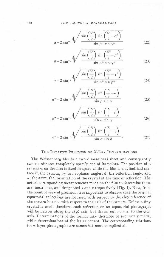
TnB RnrarrvB PnBcrsroN or X-Rav DBrBnurNATroNS
The Weissenberg film is a two dimensional sheet and consequentlytwo corirdinates completely specify one of its points. The position of areflection on the film is fixed in space while the film is a cylindrical sur-face in the camera, by two coplanar angles:6, the reflection angle, andco, the azimuthal orientation of the crystal at the time of reflection. Theactual corresponding measurements made on the film to determine theseare linear ones, and designated r and 4 respectively (Fig. 1). Now, fromthe point of view of precision, it is important to observe that the originalequatorial reflections are focussed with respect to the circumference ofthe camera but not with respect to the axis of the camera. Unless a tinycrystal is used, therefore, each reflection on an equatorial photographwill be narrow along the r(6) axis, but drawn out normal to the a(<o)axis. Determinations of the former may therefore be accurately made,while determinations of the latter cannot. The corresponding relationsfor n-layer photographs are somewhat more complicated.
p.)4L"" (T) "" (

]OURNAL MINEK LOGICAL SOCIETY OF AMERICA 421
Another source of error inherent in x-ray determinations depends uponthe fact that while s coiirdinates are ordinarily rather reliable due tofocussing, they cannot be depended upon for small values of r. This isbecause the absorption and thickness of the specimen tend to shift thecenter of the spot (Hadding, l92l) to a higher value of *. While thiseffect is a continuous function of r, the displacement is most importantfor spots near the center line of the film.
,/1.
Frc. I
A third source of error is due to the initial error in orienting the axis ofthe crystal parallel with the rotation axis. This sort of an error leads toonly a negligible error in the r cocirdinate of a reflection, but causes animportant error in 4 of approximately
Ar^u*:/ tan (2e) (28)
were e:the original angular orientation error. The resulting error incalculated co angles thus amounts to
A4-u* r Lan (2e)A , .A@mtx - -
where K:the coupling constant oI the instrument, i.e., the number ofmillimeters translation of the camera per degree of crystal rotation.This error is serious. ft can be reduced to some extent experimentally byusing a narrow layer line screen slit (which will prevent recording if theorientation ertor, e, is high) and also by increasing the coupling constant,K. There is a physical limit to K if one wishes to keep the size of theWeissenberg instrument down to practical size.
Because of the first and last sources of error discussed, truly precisedeterminations of crystallographic constants cannot be based upon anymethods involving measurements of 4, but can only be based upon meth-ods involving the measurement of r only. fn other words, any precisiondeterminations of lattice constants must be based upon measurementsof reciprocal cell translations, which correspond with direct cell inter-planar spacings.
(2e)

422 THE AMERICAN MINERALOGIST
In most cases the measurements mentioned above can be made againsta steel mil l imeter scale (Tunell, 1933, p. 183; Buerger, in press, f ig. 9) orwith a vernier caliper.l If measurements are made with the aid of charts,however, such as d-charts, Z-charts, or {-charts, several additionalsources of inaccuracy appear. In the first place, inaccuracies in the chartsthemselves reduce the precision of the measurement. Second, since non-uniform scales are inherent in charts, a vernier cannot be used in sub-dividing the chart graduations. The use of charts therefore reduces theprecision of the results sti l l further and determinations based uponchart measurements can only be considered rough determinations.
DBrBnlrrxarroN oF LrNBan LnrrrcB CoNsranrs
General Remarks
The linear lattice constants of crystals may be derived by makingmeasurements leading either directly to a, b and c or by making measure-ments leading directly to a*, b* and c*. The latter scheme, at present
the most accurate, is extremely tedious and roundabout for the obliquesystems, since the final desired result (the direct lattice constants) canonly be derived after a further knowledge of the angular lattice constantsis gained (see equations(1a)-(16)). If the latter can be only inaccuratelydetermined. the calculated linear lattice constants must also remain in-
accurately known.
Direct Determination of a, b, ond c.
It is well known that the layer line spacings of a rotating crystalphotograph lead directly to the identity period of the axis of rotation.The measurement method ordinarily employed for this purpose consistsof (or is the equivalent of) laying the fi lm directly on a Bernal (1926)
chart which has been reduced to scale for the camera diameter used,and reading off the f corirdinates of the layer lines directly. The identityperiod along the rotation axis is then
drT : - ( 30 )
rn:Iayer number
),: x-ray wavelength
f:reciprocal lattice cocirdinate of the layer
line as read on the Bernal chart.
This method leads to very inaccurate estimates of the crystallographicaxes because,

JOURNAL MINERALOGICAL SOCIETY OF AMERICA 423
(a) charts are used, a source of inaccuracy previously discussed,
(b) the reflections are, in general, unfocussed normal to the f film coiirdinate,
(c) the apparent f cod,rdinate increases as f decreases, due to absorption and thickness
of the specimen, as already discussed, and(d) orientation inaccuracies result in multiple, or broadened, layer lines.
This method can be made to yield greatly more accurate values of
the identity period sought by eliminating or minimizing inaccuracies
(a), (b), (c) and (d) in several ways:(I) Inaccuracy source (a) can be eliminated by the direct measure-
ment of the Bernal codrdinate, y, instead of f' This enables one to use
a scale and vernier. Suitable instruments for this purpose are indicated
elsewhere. The appropriate relation corresponding to (30) for computa-
tion purposes is then
T : (3 1)
where y:the height of the ath layer line measured from the zerolayer
liner:the radius of the camera
(II) Inaccuracy source (c) may be minimized by measuring only
spots of large r cocirdinates.(III) Inaccuracy source (d) may be minimized, if recognized, by the
following means: Each plane reflects to four spots on a rotation film, the
spots having cotjrdinates fi, y; *, -! i -f i, ! i -*, -y. If an orientation
error exists, the y cod,rdinates of the first two and the second two pairs of
spots will be displaced in the same direction by approximately the same
amounts. If, therefore, the difference between the +y and -y co-
<irdinates of these spot pairs is ineasured, half of this difference is nearly
the correct value of I to substitute in (31). If the form whose reflection
is under consideration contains more than one centrosymmetrical pair
of planes, as it does in the monoclinic system (but not in the triclinic
system), then each of the spots in the above *y, -y pair wiII be doubled.
The upward shifted pair and the downward shifted pair should be con-
sidered separately for this measurement method.This method can be carried out with the usual rotation photograph,
provided the camera not only has a high x (l) range, but also provided
that the film lies accurately along the camera circumference in this
region. More appropriate photographs for this pu{pose' however, may
be made by a back reflection method, since in this type of photograph
the { range then becomes the maximum possible. Such photographs are
n\,
,i" t""-'(1)

424 TEE AMERICAN MINERALOGIST
required for the increase in accuracy due to focussing, next mentioned:(IV) Focussing in the y direction may be realized along the line {:a
maximum, i.e., along the l ine n: T r. This l ine is unattainable in ordinaryrotation films because the film ends are placed in this region. If a backreflection photograph is used, however, this region is in the middle ofthe f i lm.
Ordinarily, spots will not fortuitously appear having exactly the *cocirdinates of this line. If the rough value of the identity period, l,is known, however, polychromatic radiation may be employed (as froman alloy target, for example) and multiple layer lines may be produced.Spots having r fortuitously on or very near this line will then havetheir I codrdinates focussed, and accurate values of y may be obtained.It should be observed that the geometrical aspects of this back reflec-tion method are analogous to the flat-fiIm, back reflection powdermethod of Sachs & Weerts (1930). Therefore, further accuracy isattainable by plotting the values of the lattice constant so obtained fromseveral layer lines, against Sachs and Weerts' function
ctg 0.sin 40. (32)
Extrapolation of the graph to 0:90" gives a refined value of the identityperiod.
Direct Determination oJ a*, b*, and. c*
Rough determinations of the linear reciprocal lattice constants maybe made with the aid of the Z scale using the relation
Za * , b * , c * : - '
ilr(33A)
A more exact determination of these constants,is identical with an exactdetermination of the interplanar spacings d1no1, tl1;toy. and d1s61y. Thisis easily accomplished from Weissenberg photographs (Buerger, 1935,p. 281) by measurements of the * coiirdinates of the appropriate reflec-tions. The computation in this case is
) - (33B),"^(+ :*)The precision of d, can be greatly increased with the aid of an extra-
polation method developed by Bradley and Jay (1932).In this method

IOURNAL MINERALOGICAL SOCIETY OF AMERICA 425
the values of d as computed from measurements of difierent spots of
d.ifierent reflection order, n, are plotted against cos2d. The extrapolation
of the curve (which is a straight line for high values of 0) so obtained,
to g:90o leads to the correct value of d. From this the correct value of
a*, b*, or c* can be obtained by taking the reciprocal of the appropriate
multiple of d.This important method of attaining precision in o*, b* and c* is of the
greatest value in attaining maximum precision in other crystallographic
constants. A complete treatment of the subject will appear elsewhere
(Buerger, in press).
DBrBnlrrNarroN oF ANcuran L.tr:ncp CoNsraNrs
Determi.nation of a, B and' 7
Method of Dome Offsets. The n-layer reflections from the orthodomes
of monoclinic crystals, and from macrodomes, brachydomes, and
prisms of triclinic crystals, correspond with non-central reciprocal lattice
lines (Buerg er,1934, p. 375). The amount of ofiset or departure , i l , ftom
a central lattice line can be measured in the equi-inclination method
with the aid of an equi-inclination lattice line template. This offset, d,
is a function of the reciprocal lattice level height, f, and the direct lattice
angle a, 0, ory, as graphically shown in Figs. 2 and 4. From these figures
it is evident that in either the monoclinic or triclinic system, the angular
offset of the nth reciprocal lattice line of points is the direct crystallo-
graphic angle B. A measure of B may evidently be obtained with the aid
of the following relation:
?
tan o: I . (34)d
For chart determinations, f may be derived from the rotation photo-
graph with the aid of the Bernal chart, and d may be derived from the
nlayer Weissenberg film by fitting the d interval template over the film
and reading d.f coslt directly from the template. This method of assigning
values to oblique angles has been suggested by Miss Crowfoot (1935,
p .220 ) .A great gain in accuracy may be obtained in this method by avoiding
the use of the chart and substituting a steel scale measurement of d.
Because of symmetry, a direct measure ol d, may be obtained in the
monoclinic system by measuring the * co<irdinate of the orthodome
reflection nearest the center of the film (Fig. 3). If ra is the cijrdinate of
011, then

426 TH E A MEMCAN MINERALOGIST
d:2 cos r"^(+ #)This method is not of general application and cannot be applied in
the triclinic system where symmetry is lacking. A still bettei way ofdetermining d, however, is through the angular lag in the reflection ofthe dome series behind the pinacoid series, due to d. This angular lag,,t,, is a very sensitive measure of. d, Ior reciprocal lattice points near theorigin, i.e., for dome reflections near the center of the fi lm. The strategyof determinating d varies in monoclinic and triclinic cases.
Frc. 2
Monoclinic case. The following discussion applies to a monocliniccrystal rotated about the c-axis, but by interchange of notation, appliesalso to rotation about the a-axis. The upper part of Fig. 2 shows theimportant aspects of the plan of the first (or any n-) leveroi the reciprocallattice' The beaded lines are the orthodome and clinodome series ofreciprocal lattice points on this level. The latter is displaced a distance,
(34.A)
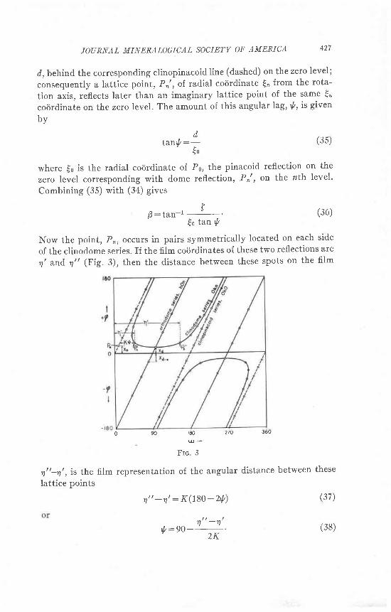
JOURNAL MINERALOGICAL SOCIETV OF AMERICA 427
d, behind the corresponding clinopinacoidline (dashed) on the zero level;
consequently a lattice point, Pn', of radial codrdinate {, from the rota-
tion axis, reflects later than an imaginary lattice point of the same {"
coijrdinate on the zero level. The amount of this angular lag,*, is given
by
where {o is the radial cocirdinate of P6, the pinacoid reflection on the
zero level corresponding with dome reflectiott, Pn' , on the nth level'
Combining (35) with (34) gives
B : tan - r f
to tan t
Now the point, P,, occurs in pairs symmetrically located on each side
of the clinodome series. If the film cocirdinates of these two reflections are
q' and. n" (Fig. 3), then the distance between these spots on the fi lm
o 90 180 270 J6u
Frc. 3
n"-n', is the film representation of the angular distance between these
lattice points
(37)
(3s)dtawlt:-
<0
(36)
n" -n ' : K(180-2' t / )
l , In - nt : 9 0 -' 2 K (38)

428 THE AMEKICAN MINERA LOGIST
Combining (36) with (38) gives
In this equation, f, the reciprocal lattice layer height, is determinedfrom the rotation photograph and may have a value refined as demon-strated on page 424, and {e has a value determined from the c c.-cirdinate of the spot P6l on the zero layer with the aid of the relationgiven by Buerger (1934, p. 362, equa.tions 10 or 11).
ro:2 sin (+ $) (40)\ 2 2rr/
A considerably more accurate estimate of {s may be had, however, bycomputing spacing, dloroy, from a number of {s measurements of the(0fr0) series, and determining a refined value of dloro; by the method ofBradley and Jay (1932). {6 is derived by the reciprocal relation:
Itt:
a* ., (4r)
Returning to equation (39), it may be said that, of the variables indi-cated there, {o can be determined with relatively great precision. fcan also be determined with considerable precision by the methods out-lined on page 424. The angular difference represented by n,,-rt,is sub-ject to the main lack of precision. This includes the matters mentionedon page 421, as well as the error of setting the equi-inclination angle(Buerger, 1936, p. 96). An error in this setting, however, can be detected,if present, by a lack of straightness of the orthodome series of reflections.
Triclinic case. rn Figs. 4 and 5 the triclinic case corresponding withthe monoclinic case of Figs. 2 and, 3 is shown. The triclinic case ofiersa more complicated situation and the lack of specialization makes newmeasurement strategies necessary.
The value of {o can no longer be used in computing d. Instead, therelation
dsin ry':- (42)
must be used. Furthermore, the reflection p, no longer has a symmetricalcompanion, so some other method must be devised for the measurementof the film equivalent of 'y'. The difficulty here is that there is no zero onthe n layer film from which to measure ry' intervals. The diffculty can
o : tan - r ( ! run\40
(3e)

IOURNAL MINERALOGICAL SOCIETY OF AMERICA
Frc 4
429
I+f
o 90 180 270 360( l J+
Frc. 5
be overcome if some equivalent fiducial mark can be made both on the
zero and nlayer films. This can be accomplished in either of two ways:
(a) The direct beam may be recorded on each film when the crystal rotation spindle
has identical settings. The fiducial mark of the z layer film is then at - 2s compared

430 THE AMEMCAN MINEfuALOGIST
with that on the equator frlm, where s is given by (43) below. This method requiresa very accurate crystal rotation spindle setting, which is not very easily accom-plished, and also records the fiducial mark in the form of a shadow, insiead of areflection.
(b) The recommended method is to record both zero and. n-layer on the same filmwithout any experimental changes except the change in equi-inclination setting,and the corresponding changes in camera settings (Buerger, 1936, p. 94).
The latter change must be exact for this purpose, and is possible withthe instrument designed by the writer (1936). rf the camera is set on itscarriage with the camera scale reading zero for the zero layer, the setting,s, for the ath layer is
s: rr tan p @3\where rp:the effective fi lm radius
0: the equi-inclination setting
With the zero andnlayerc recorded on the same fi lm, the angle of lag,ry', of the dome reflections behind the pinacoid reflections can be meas-ured (Fig. 5). For a definite reference point in the pinacoid reflectionline, select a pinacoid reflection preferabry with an z iocjrdinate near tothe corresponding cocirdinate of the dome reflection p.. rl now. thecocirdinates of the several important points on the film are:
Tn1 !rn: the film corirdinates of the dome reflection p,
Io7 fin: the film cocirdinates of a pinacoid reflection p6
T', rn: the fi lm codrdinates of a point on the p6 reflection seriesthen, Kt : (n, -no)- (n, -n i , l4)
and since tanr:L, (Buerger , lg34,p. 366),n
(_r, - xo)K 9 : ( n , , - r r ) -
o n z
Substituting (a6) in (42) gives:
(4s)
(46)
d:t [1f . (1:- . , ) l ] e7)^ t 'n
1l( L(r^-no) --
t t .
rn the tricl inic case, B (or a, by using the second set of dome offsets)is determinable by (3a). The value of d. may be crudely obtained forthis equation by fitting the equi-inclination chart to the spots on the film.rt may be obtained much more accurately directry from steel scareand vernier f i lm measurements by combining (47) and, (34) which gives:

JOURNAL MINERALOGICAL SOCIETY OF AMERICA
?(
431
(48)0: tan- t
c",r"{f[t4*-ro)-#]l
The sources of error in the solution of (aS) are similar to those en-
countered in the monoclinic case, and there are two additional sources
of possible inaccuracy: a possible inaccuracy in the camera setting, s,
for the ntt-layer, and the inferior accuracy of the determination of {,
as compared with to.Method of triangulation. The identity periods of a crystal along o,
c, and [101] may be obtained from rotation photographs about these
three directions. These three identity periods form a triangle whose ob-
from the six corresponding rotation photographs'
This method of calculating interaxial angles is not ordinarily of much
practical importance since, if the crystal is suficiently well developed
io pe.*it orientations of the rotation axes parallel with these zones, the
.eciprocal interaxial angles may be measured with an optical goniometer
and the direct interaxial angles calculated from them'
Direct Determi.nation of o*, 0*, and 7*
Method of c.r separations. If the D axis zero layet weissenberg film is
placed on the coiirdinate measuring device so that the measuring line is
parallel with the Zlines of reflection orders, then the film measurement
tetween the reflection orders of (100) and (001) is
(4e)m: K9* sin v.
The easiest method of arriving at any crystallographic angle is thus
this measurement of interplanar angles on equatorial Weissenberg films'
unfortunately it is also qrrite inaccurate for reasons stated onpage 424.
Method of triangulation. The reciprocal lattice vectors o*, c*, [101]*
form a triangle which includes the reciprocal lattice angle B*' These three
Iinear elements may be very accurately determined, hence B* can be
very accurately computed' Similarly a* can be computed from b*' c*'
[011]*, and y* can be very accurately computed from o*' b*' [110]*'
This method is the most accurate one for determining any crystallo-
graphic angles because the angles depend upon spacing measurements'
which can be very accuratelY made.

432 TEE A MERICAN MINEKALOGIST
Tnn DBrpnMrNATroN or, Ar,r, LarrrcB Cowsrawrslnolr ONr Cnysrar SBrrrNc
suppose that the crystal is undescribed. The needre axis (or zone suffi-ciently well developed for orientation) may be chosen as the c-axis. Thestatus of information determinabre from the photographs is then asfollows:
Computable from film measurements discussed: a*, b*, c, d, 0,.y*Remaining direct lattice constants to be foun d.: a, b, .y

TOURNAL MINEKALOGICAL SOCIETY OF AMER]CA 433
Oprtvruu PnocBounr LBaorNc ro Maxruulr Accunacv
rN Lerrrcn CoNsreNrs
It has been pointed out that measurements of 4 (t'r) are subject to
maximum errors and that therefore computations based upon these
measurements are least reliable, while measurements of r (d) are made
with great accuracy. Add to this the fact that the latter measurements
are transposable without error into interplanar spacing values, d(ft/',),
which can be refined by Bradley and Jay's method, and it is apparent
that crystal lattice constants which can be expressed as functions of r
measurements alone can be determined with the greatest precision.
Now, all lattice constants can be expressed in terms of such measure-
ments, provided only that a crystal is available which is sufficiently well
developed to permit orientations for rotations about any three non-
coplanar axes. Suppose that these axes are chosen as the three crystallo-
graphic axes. Then, with the aid of three equatorial Weissenberg photo-
graphs, the data given in column II below can be directly determined.
III
rotation axisprecisely determinable
constants
additional contants pre-
cisely computable from
values in column II
b*, [o1T]*, c+a*,[ l0I]*, c*b*,ll10l*, a*
From the six distinct linear reciprocal values in column II, the reciprocal
lattice angles in column III can be precisely computed by the method
of triangulation. From these reciprocal angles, the direct lattice angles
may be computed with the aid oI (22), (23), and (24). With the values of
a*, b*, c*; o*, A*,'y*; a, B, and 7, which are then available, the values
oI a, b, and. c may be precis€ly computed with the aids of equations (14),
(15 ) and (16 ) .All these values rest solely upon refined spacing measurements. The
results are easily comparable, if not superior, to those computed from
interfacial angle measurements made with an optical goniometer, and
this accuracy is obtainable without much precaution. The method is of
such obvious promise that the writer (1936 C) has developed a special
back-reflection Weissenberg instrument for taking full advantage of it.
q*
"y*

tJ+ THE AMERICAN MINERA LOGIST
pendent of crystal imperfections which, in ordinary optical goniometricwork, prevent the attainment of even the anguJar -easuri.rg accuracypossible in the instrument.
T^l.e 1. TanurerroN or coupurlrroNar, Fonuur,e,r NEcESSAR' rN TrrE DnrnrurNauoNol A'r Letrrca co*sraNrs nou oNB crvsra'- Sn*r*c. .14, connncr Fonuur,e .on
Moxoclrxrc Cnvsrlr; Z, lon TnrcrrNrc Crysral.
Irotation
axrs
I I III V I V Iconstants I formula formula I constants I lormula fordirectly for rough I for accurate I indirectly I computation
computable I computation I computation I computable I of ualue.from chart I from steel of V from
values of fIscalemeasureme
IV
b "c*a *
p7
(30)(33A)(33A)(4e)(34)(s4)
(33A)(30)(33A)(34)(4e)(34)
(33A)(33A)(30)(34)(34)(4e)
(31)(33B)(338)
triangulation(3eM) (48T)
(48)
bcq
(1s)(16)(21)
(16)
b
a
^v
a*
c
d
a
^l
(338)(3 1)(338)(48)
triangulation(48)
(338)(33B)(3 1)(48)
(3eM) (48T)triangulation
(r4)(1s)

JOUKNAL MINERALOGICAL SOCIETY OF AMEKICA 4.35
RBTBnBNcBS
Benrn, T. F. W., and Turor,r,, G. (1933): Arner. Mi'n.,18,187-194'
BenNer, J. D. (1926): Proc. Roy. Soc. London, (A) f13' l7I-160'
Bn.rrrnv, A. J., and Jav, A. H . (1932): Proc. Phys.50c.44r 563-579'
Buencrn, M. J. (1934): Zeits. Kri,st., (A) 88' 356-380.- (1935): zeits. Krist., (A) 9r, 255-289.- (1936A): zei.ts. Krist., (L) 94,87-99.- (19368): Amer. Min.,21,575-583.- (1936c) : Amer. Min., 21, (12, Pt. 2), 13.- (in press): Zeils. Krisl.Cnowroor, D. (1935) : Zeits. Krist., (L) 90, 218-222.
Got-oscmror, V. (1886): In'der iler Krystall,formen, l, l4-Berlin'
HeootNG, A. (1921): Cbl. Min.,631-636.Her-r-e, F. (1932): Zeits. Kri.st., (A) 82,321-323.Kuus, E. H., and Mnz, G' (l9ol): Zeits. Kri'st.,34r 389-396'
Sacus, G., and Wnnnts, J. (193O): Zeits. Phys.,6Or 481-490'
Tuxnr,r, , G. (1933): Amer. Min., l8' 181-186.