Embed Size (px)
Citation preview
The World Leader in Manufacturing Real Flaws
Specimen Catalogue www.FlawTech.com

www.flawtech.com flaw manufacturing technology
TABLE of CONTENTSFLAWED SPECIMEN CATEGORIESFLAWTECH DISCONTINUITIES LISTFLAW CROSS SECTION VIEWSFLAW CROSS SECTION VIEWS STANDARD KITSSTANDARD RADIOGRAPHIC KITSTANDARD MAGNETIC PARTICLE / LIQUID PENETRANT KITSTANDARD ULTRASONIC KITNDT DEMONSTRATION KITSTANDARD VISUAL KITCAST SAMPLE SETPRACTICAL EXAM SPECIMENSULTRASONIC PRACTICAL EXAM SPECIMENSMT/PT & VT PRACTICAL EXAM SPECIMENSADVANCED SPECIMENSADVANCED SPECIMENSADVANCED SPECIMENSCORROSION, EROSION, & LAMINATION PLATESAPI-UT-1 FLAWED SPECIMEN KITAPI-UT-MINI KITAPI-RP-2X SPECIMEN KITAWS/CWI VISUAL SPECIMEN KITTRAVELER CWI VISUAL TRAINING KITAWS/CWI PLUS PT ENDORSEMENT KITAWS STRUCTURAL WELD SEISMIC KITSOCKET WELD SPECIMEN KITBORESCOPE SAMPLE SETBOILER TUBE DAMAGE KITASME SECTION XI APPENDIX VII KITASME SECTION XI APPENDIX VIII KITSUT CALIBRATION BLOCKSPDI UT CALIBRATION BLOCKSASME UT CALIBRATION STANDARDSPDI UT 10 CALIIBRATION BLOCKS
FLAWED SPECIMEN CATEGORIESFLAWTECH DISCONTINUITIES LISTFLAW CROSS SECTION VIEWSFLAW CROSS SECTION VIEWS STANDARD KITSSTANDARD RADIOGRAPHIC KITSTANDARD MAGNETIC PARTICLE / LIQUID PENETRANT KITSTANDARD ULTRASONIC KITNDT DEMONSTRATION KITSTANDARD VISUAL KITCAST SAMPLE SETPRACTICAL EXAM SPECIMENSULTRASONIC PRACTICAL EXAM SPECIMENSMT/PT & VT PRACTICAL EXAM SPECIMENSADVANCED SPECIMENSADVANCED SPECIMENSADVANCED SPECIMENSCORROSION, EROSION, & LAMINATION PLATESAPI-UT-1 FLAWED SPECIMEN KITAPI-UT-MINI KITAPI-RP-2X SPECIMEN KITAWS/CWI VISUAL SPECIMEN KITTRAVELER CWI VISUAL TRAINING KITAWS/CWI PLUS PT ENDORSEMENT KITAWS STRUCTURAL WELD SEISMIC KITSOCKET WELD SPECIMEN KITBORESCOPE SAMPLE SETBOILER TUBE DAMAGE KITASME SECTION XI APPENDIX VII KITASME SECTION XI APPENDIX VIII KITSUT CALIBRATION BLOCKSPDI UT CALIBRATION BLOCKSASME UT CALIBRATION STANDARDSPDI UT 10 CALIIBRATION BLOCKS
123456789
1011121314151617181920212223242526272829303132
123456789
10111213141516171819202122232425262728293031323334

www.flawtech.com flaw manufacturing technology
FLAWED SPECIMEN CATEGORIESSTANDARD SPECIMEN
ADVANCED SPECIMEN
CRITICAL SPECIMEN
• Have a tolerance of +/- 0.150” (4mm).
• Includes all standard kit specimens and all UT & MT / PT practical exam specimens.
• Designed to enhance the training and development of new and veteran NDT technicians.
• Normally smaller in size and less expensive than Advanced and Critical specimens.
• Basic Document Package with CAD drawings is included with each kit or exam specimen.
• Custom specimens are available at this level of tolerance.
• Have a tolerance of +/- 0.080” (2mm).
• Includes all advanced specimens, API-UT-1 kit & all ASME section XI appendix VII specimen bank.
• Designed to enhance the training & qualification of level I, II, & III personnel with regards to SNT-TC-1 A, EN473 & PCN.
• Stock Advanced Specimens are larger in size than the standard specimen and higher tolerance.
• Document package with CAD drawings is included with each kit or individual Advanced Specimen.
• Custom specimens are available at this level of tolerance.
• Have a tolerance of +/- 0.040” (1mm).
• Includes all ASME Section XI Appendix VIII specimens & most of the custom designed specimens.
• Designed to customer specifications for their training & qualification of NDT personnel, equipment, and procedures.
• Size of specimens range from a small bolt for the space shuttle to a 20,000 pound reactor nozzle.
• Detailed documentation is included with specimens. Contact FlawTech for exact details.
• Custom specimens are available at this level of tolerance.
1 www.flawtech.com
www.flawtech.com flaw manufacturing technology
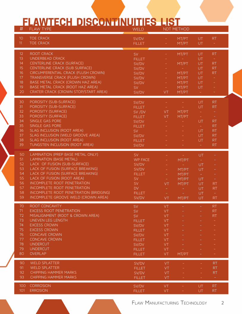
FLAWTECH DISCONTINUITIES LIST# FLAW TYPE WELD NDT METHOD
121314151617181920
ROOT CRACKUNDERBEAD CRACKCENTERLINE CRACK (SURFACE)CENTERLINE CRACK (SUB SURFACE)CIRCUMFERENTIAL CRACK (FLUSH CROWN)TRANSVERSE CRACK (FLUSH CROWN)BASE METAL CRACK (CROWN HAZ AREA)BASE METAL CRACK (ROOT HAZ AREA)CRATER CRACK (CROWN STOP/START AREA)
SV FILLETSV/DVSV/DV SV/DV SV/DV SV/DV SVSV/DV
--------
VT
MT/PT-
MT/PT-
MT/PT MT/PTMT/PTMT/PTMT/PT
UTUTUTUTUTUTUTUT-
RT-
RTRTRT----
30313233343536373839
POROSITY (SUB-SURFACE)POROSITY (SUB-SURFACE)POROSITY (SURFACE)POROSITY (SURFACE)SINGLE GAS PORESINGLE GAS PORESLAG INCLUSION (ROOT AREA)SLAG INCLUSION (WELD GROOVE AREA)SLAG INCLUSION (ROOT AREA)TUNGSTEN INCLUSION (ROOT AREA)
SV/DVFILLETSV /DVFILLETSV/DVFILLETSV SV/DV FILLETSV/DV
--
VTVT------
--
MT/PTMT/PT
------
UTUT--
UT-
UTUTUT-
RTRT--
RTRTRTRTRTRT
50515253545556575859
LAMINATION (PREP BASE METAL ONLY)LAMINATION (BASE METAL)LACK OF FUSION (SUB-SURFACE)LACK OF FUSION (SURFACE BREAKING)LACK OF FUSION (SURFACE BREAKING)LACK OF FUSION (ROOT AREA)INCOMPLETE ROOT PENETRATIONINCOMPLETE ROOT PENETRATIONINCOMPLETE ROOT PENETRATION (BRIDGING)INCOMPLETE GROOVE WELD (CROWN AREA)
SVWP FACESV/DV SV/DVFILLETSV SV DV FILLETSV/DV
------
VT--
VT
-MT/PT
-MT/PTMT/PT MT/PTMT/PT
--
MT/PT
UT-
UTUT-
UTUTUTUTUT
------
RTRT-
RT
7071727374757677787980
ROOT CONCAVITYEXCESS ROOT PENETRATIONMISALIGNMENT (ROOT & CROWN AREA)UNEVEN LEG LENGTHEXCESS CROWNEXCESS CROWNCONCAVE CROWNCONCAVE CROWNUNDERCUTUNDERCUTOVERLAP
SVSVSVFILLETSV/DVFILLETSV/DV FILLETSV/DVFILLETFILLET
VTVTVTVTVTVTVTVTVTVTVT
----------
MT/PT
-----------
RTRTRT--------
90919293
WELD SPLATTERWELD SPLATTERCHIPPING HAMMER MARKSCHIPPING HAMMER MARKS
SV/DVFILLETSV/DVFILLET
VTVTVTVT
----
----
RTRTRT-
1011
TOE CRACKTOE CRACK
SV/DVFILLET
--
MT/PTMT/PT
UTUT
RT-
100101
CORROSIONERROSION
SV/DVFILLET
VTVT
--
UTUT
RTRT
2Flaw ManuFacturing technology
www.flawtech.com flaw manufacturing technology
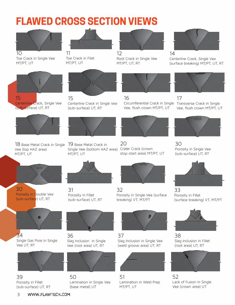
10 Toe Crack in Single Vee MT/PT, UT
11Toe Crack in Filet MT/PT, UT
12Root Crack in Single VeeMT/PT, UT, RT
14Centerline Crack, Single Vee (surface breaking) MT/PT, UT, RT
15Centerline Crack, Single Vee (sub-surface) UT, RT
15Centerline Crack in Single Vee (sub-surface) UT, RT
16Circumferential Crack in Single Vee, flush crown MT/PT, UT
17Transverse Crack in Single Vee, flush crown MT/PT, UT
18 Base Metal Crack in Single Vee (top HAZ area) MT/PT, UT
19 Base Metal Crack in Single Vee (bottom HAZ area) MT/PT, UT
20Crater Crack (crown stop-start area) MT/PT, UT
FLAWED CROSS SECTION VIEWS
3 www.flawtech.com
30Porosity in Single Vee (sub-surface) UT, RT
31Porosity in Fillet (sub-surface) UT, RT
30Porosity in Double Vee (sub-surface) UT, RT
32Porosity in Single Vee (surface breaking) VT, MT/PT
33Porosity in Fillet(surface breaking) VT, MT/PT
34Single Gas Pore in SingleVee UT, RT
36Slag Inclusion in SingleVee (root area) UT, RT
37Slag Inclusion in Single Vee (weld groove area) UT, RT
38Slag Inclusion in Fillet (root area) UT, RT
39 Porosity in Fillet (sub-surface) UT, RT
50 Lamination in Single Vee (base metal) UT
51Lamination in Weld PrepMT/PT, UT
52Lack of Fusion in Single Vee (crown area) UT
www.flawtech.com flaw manufacturing technology
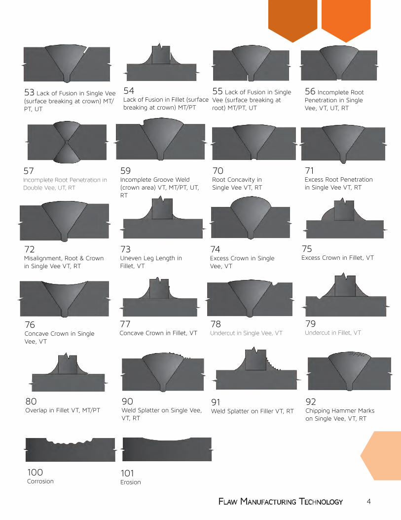
53 Lack of Fusion in Single Vee (surface breaking at crown) MT/PT, UT
54Lack of Fusion in Fillet (surface breaking at crown) MT/PT
55 Lack of Fusion in Single Vee (surface breaking at root) MT/PT, UT
4Flaw ManuFacturing technology
56 Incomplete Root Penetration in Single Vee, VT, UT, RT
57Incomplete Root Penetration in Double Vee, UT, RT
59 Incomplete Groove Weld (crown area) VT, MT/PT, UT, RT
72Misalignment, Root & Crown in Single Vee VT, RT
73Uneven Leg Length in Fillet, VT
74 Excess Crown in Single Vee, VT
75Excess Crown in Fillet, VT
76Concave Crown in Single Vee, VT
77Concave Crown in Fillet, VT
70Root Concavity in Single Vee VT, RT
71Excess Root Penetration in Single Vee VT, RT
78Undercut in Single Vee, VT
79Undercut in Fillet, VT
80Overlap in Fillet VT, MT/PT
90Weld Splatter on Single Vee, VT, RT
91Weld Splatter on Filler VT, RT
92Chipping Hammer Marks on Single Vee, VT, RT
100Corrosion
101Erosion

www.flawtech.com flaw manufacturing technology
VT Kit
EACH KIT CONTAINS: • 10 Carbon Steel Specimens per kit / custom alloys available •20 “Real” flaws per kit / 2 per specimen randomly placed • “Free” Carrying Case •Detailed Document Package with CAD drawings
See the following pages for Kit details.
Reference Radiographs
•Total of 16 Radiographs •Showing 20 Real Flaws •Plus 6 Processing Defects • Includes Documentation
and Film
Demonstration Kit #DK-1 (Great Introduction to NDT kit)
#RR-1
#RK-1 #UK-1 #MK-1 #VK-1
STANDARD KITS
RT Kit UT Kit MT/PT Kit
FlawTech Standard Kit Specimens are designed to enhance the training and development of new and veteran technicians. Kits will assist with basic flaw detection and sizing of real flaws found in common weld geometries. Each kit is shown in further detail on the following pages.
•5 Carbon Steel Specimens •2 RT, 1 UT, 1 VT & 1 MT/PT Specimens •Total Of 11 Real Flaws • Includes Documentation and Case
5

www.flawtech.com flaw manufacturing technology 6
THE RADIOGRAPHIC KIT CONTAINS:8 Plates, 1 Pipe & 1 Tee / Carbon Steel
Each specimen contains 2 “REAL FLAWS,” randomly placed.
Kit Specifications: 10 specimens (5) Plates: 0.375”T x 4” x 8” (3) Plates: 0.625”T x 4” x 8” (1) Tee: 0.375”T x 4” x 8” x 4” (1) Pipe: 4” Sch80 (0.337” wall)
Actual X-Ray film is provided for each specimen. Specimens are packaged in 2 FREE CARRYING CASES. Complete with Document Package with “Flaw Truth” documented by CAD drawings with a Standard Tolerance of (+ / -) 0.150” (4mm), CAD Drawings, RT Film and Test Sheets.
The Standard Radiographic Examination Kit contains 20 flaws similar to those shown in the cross section drawings below.
Visit www.flawtech.com or call for price information.
Flaws Included:12 - Root Crack in SV14 - Centerline Crack SV (Surface breaking)15 - Centerline Crack, SV (Sub-surface)30 - Porosity SV / DV31 - Porosity Fillet (sub surface)34 - Single Gas Pore SV 36 - Slag Inclusion SV (root area)37 - Slag Inclusion SV (weld groove area) 38 - Slag Inclusion Fillet (root area)39 - Tungsten Inclusion SV (root area)56 - Incomplete Root Penetration SV 57 - Incomplete Root Penetration DV59 - Incomplete Groove Weld (crown area)70 - Root Concavity SV 71 - Excess Root Penetration SV72 - Misalignment Root & Crown SV90 - Weld Splatter SV 92 - Chipping Hammer Marks SV
STANDARD RADIOGRAPHIC TESTING KIT#RK-1
Shipping Weight 65 lbs
See Pages 3-5 for Cross Section Views

www.flawtech.com flaw manufacturing technologywww.flawtech.com7
Flaws Included:10 - Toe Crack SV 11 - Toe Crack Fillet12 - Root Crack in SV14 - Centerline Crack SV (surface breaking)16 - Circumferential Crack SV (flush crown)17 - Transverse Crack in SV (flush crown)18 - Base Metal Crack SV (top HAZ area)19 - Base Metal Crack SV (bottom HAZ area)20 - Crater Crack SV (surface stop-start area)32 - Porosity SV (surface breaking)33 - Porosity fillet (surface breaking)51 - Lamination Weld Prep53 - Lack of Fusion SV (surface breaking at crown)54 - Lack of Fusion SV (surface breaking at root)55 - Lack of Fusion SV (surface breaking at root)80 - Overlap Fillet
THE MT/PT KIT CONTAINS:8 plates & 2 Tees / Carbon Steel
Each specimen contains 2 “REAL FLAWS,” randomly placed.
Kit Specifications: 10 specimens (8) Plates: 0.25”T x 4” x 8” (2) Tee: 0.25”T x 4” x 8” x 4”
Specimens are packaged in a FREE CARRYING CASE (6” x 16” x 20”). Complete with Document Package with “Flaw Truth” documented by CAD drawings with a Standard Tolerance of (+ / -) 0.150” (4mm), Certificate of Conformance, and Test Sheets.
The Standard MT/PT Kit contains 20 “real” flaws similar to those shown in the cross section drawings below.
Optional PT Kit with STAINLESS SPECIMENS
STANDARD MAGNETIC PARTICLE/ LIQUID PENETRANT KIT#MK-1
Shipping Weight 35 lbs
See Pages 3-5 for Cross Section Views
www.flawtech.com flaw manufacturing technology
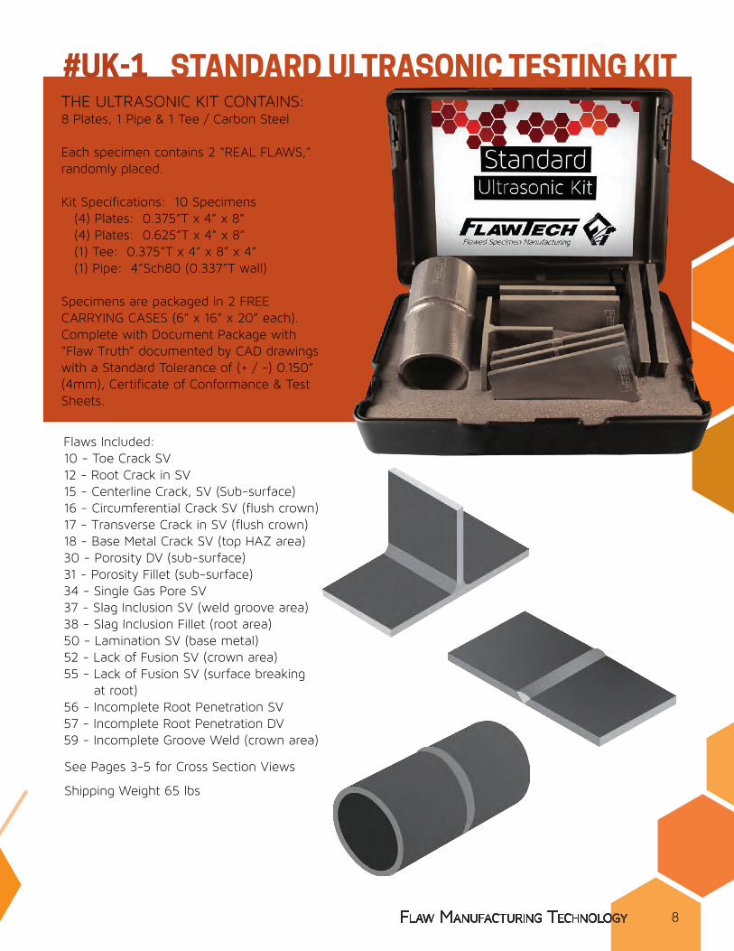
THE ULTRASONIC KIT CONTAINS:8 Plates, 1 Pipe & 1 Tee / Carbon Steel
Each specimen contains 2 “REAL FLAWS,” randomly placed.
Kit Specifications: 10 Specimens (4) Plates: 0.375”T x 4” x 8” (4) Plates: 0.625”T x 4” x 8” (1) Tee: 0.375”T x 4” x 8” x 4” (1) Pipe: 4”Sch80 (0.337”T wall)
Specimens are packaged in 2 FREE CARRYING CASES (6” x 16” x 20” each). Complete with Document Package with “Flaw Truth” documented by CAD drawings with a Standard Tolerance of (+ / -) 0.150” (4mm), Certificate of Conformance & Test Sheets.
Flaws Included:10 - Toe Crack SV 12 - Root Crack in SV15 - Centerline Crack, SV (Sub-surface)16 - Circumferential Crack SV (flush crown)17 - Transverse Crack in SV (flush crown)18 - Base Metal Crack SV (top HAZ area)30 - Porosity DV (sub-surface)31 - Porosity Fillet (sub-surface)34 - Single Gas Pore SV 37 - Slag Inclusion SV (weld groove area) 38 - Slag Inclusion Fillet (root area)50 - Lamination SV (base metal) 52 - Lack of Fusion SV (crown area) 55 - Lack of Fusion SV (surface breaking at root)56 - Incomplete Root Penetration SV 57 - Incomplete Root Penetration DV59 - Incomplete Groove Weld (crown area)
STANDARD ULTRASONIC TESTING KIT
Shipping Weight 65 lbs
#UK-1
flaw manufacturing technology 8
STANDARD MAGNETIC PARTICLE/ LIQUID PENETRANT KIT
See Pages 3-5 for Cross Section Views
www.flawtech.com flaw manufacturing technologywww.flawtech.comwww.flawtech.com9
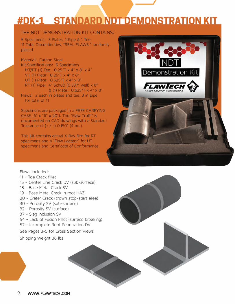
5 Specimens: 3 Plates, 1 Pipe & 1 Tee 11 Total Discontinuties, “REAL FLAWS,” randomly placed
Material: Carbon SteelKit Specifications: 5 Specimens MT/PT (1) Tee: 0.25”T x 4” x 8” x 4” VT (1) Plate: 0.25”T x 4” x 8” UT (1) Plate: 0.625”T x 4” x 8” RT (1) Pipe: 4” Sch80 (0.337” wall) x 8” & (1) Plate: 0.625”T x 4” x 8” Flaws: 2 each in plates and tee, 3 in pipe, for total of 11
Specimens are packaged in a FREE CARRYING CASE (6” x 16” x 20”). The “Flaw Truth” is documented on CAD drawings with a Standard Tolerance of (+ / -) 0.150” (4mm).
This Kit contains actual X-Ray film for RT specimens and a “Flaw Locator” for UT specimens and Certificate of Conformance.
STANDARD NDT DEMONSTRATION KIT#DK-1
Flaws Included:11 - Toe Crack fillet15 - Center Line Crack DV (sub-surface)18 - Base Metal Crack SV 19 - Base Metal Crack in root HAZ 20 - Crater Crack (crown stop-start area)30 - Porosity SV (sub-surface) 32 - Porosity SV (surface)37 - Slag Inclusion SV54 - Lack of Fusion Fillet (surface breaking)57 - Incomplete Root Penetration DV
THE NDT DEMONSTRATION KIT CONTAINS:
Shipping Weight 36 lbs
See Pages 3-5 for Cross Section Views

www.flawtech.com flaw manufacturing technologyFlaw ManuFacturing technology
Flaws Included:20 - Crater Crack SV (surface stop-start area)32 - Porosity SV (surface breaking)33 - Porosity fillet (surface breaking)56 - Incomplete Root Penetration SV 59 - Incomplete Groove Weld (crown area)70 - Root Concavity SV 71 - Excess Root Penetration SV72 - Misalignment Root & Crown SV73 - Uneven Leg Length Fillet74 - Excess Crown SV 75 - Excess Crown Fillet76 - Concave Crown SV 77 - Concave Crown Fillet 78 - Undercut SV79 - Undercut Fillet80 - Overlap Fillet90 - Weld Splatter SV91 - Weld Splatter on Filler
THE VISUAL KIT CONTAINS:7 Plates & 3 Tees / Carbon Steel
Each specimen contains 2 “REAL FLAWS,” randomly placed.
Kit Specifications: 10 Specimens (7) Plates: 0.25”T x 4” x 8” (3) Tee: 0.25”T x 4” x 8” x 4”Flaws: 2 each specimen, for total of 20
Specimens are packaged in a FREE CARRYING CASE (6” x 16” x 20”). Complete with Document Package with “Flaw Truth” documented by CAD drawings with a Standard Tolerance of (+ / -) 0.150” (4mm), Certificate of Conformance & Test Sheets.
The Standard Visual Examination Kit contains 20 flaws similar to those shown in the cross section drawings below.
STANDARD VISUAL KIT#VK-1
flaw manufacturing technology 10
Shipping Weight 65 lbs
See Pages 3-5 for Cross Section Views
www.flawtech.com flaw manufacturing technology
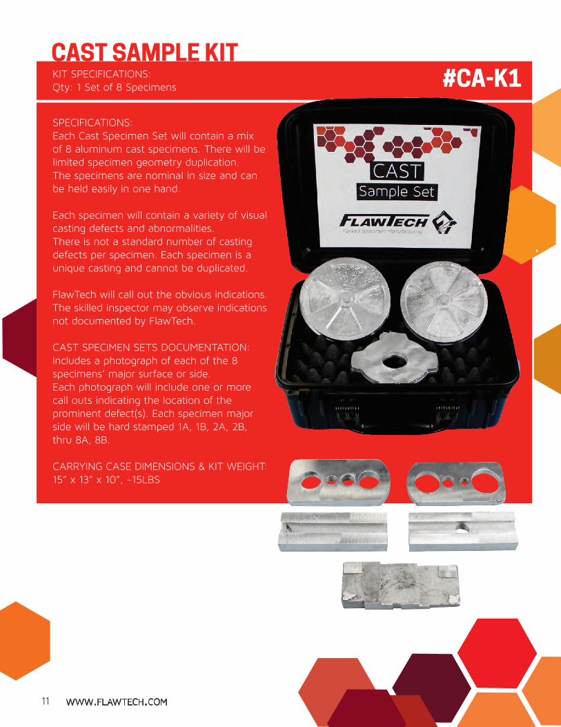
PRACTICAL EXAM SPECIMENSKIT SPECIFICATIONS:Qty: 1 Set of 8 Specimens
CAST SAMPLE KIT#CA-K1
11
SPECIFICATIONS:Each Cast Specimen Set will contain a mix of 8 aluminum cast specimens. There will be limited specimen geometry duplication.The specimens are nominal in size and can be held easily in one hand.
Each specimen will contain a variety of visual casting defects and abnormalities.There is not a standard number of casting defects per specimen. Each specimen is a unique casting and cannot be duplicated.
FlawTech will call out the obvious indications.The skilled inspector may observe indications not documented by FlawTech.
CAST SPECIMEN SETS DOCUMENTATION:Includes a photograph of each of the 8 specimens’ major surface or side.Each photograph will include one or more call outs indicating the location of the prominent defect(s). Each specimen major side will be hard stamped 1A, 1B, 2A, 2B, thru 8A, 8B.
CARRYING CASE DIMENSIONS & KIT WEIGHT:15” x 13” x 10”, ~15LBS
www.flawtech.com flaw manufacturing technology
DESIGN SPECIFICATIONS
See the following pages for Kit details.
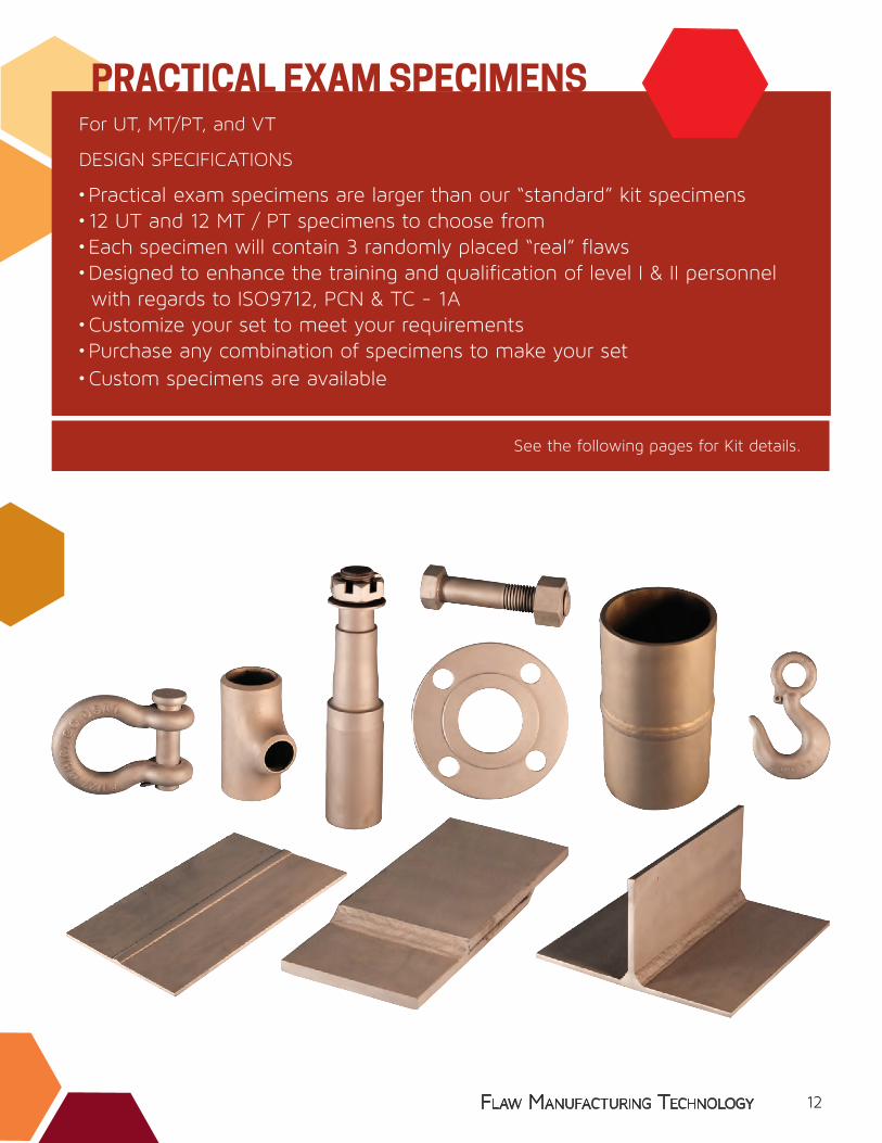
PRACTICAL EXAM SPECIMENSFor UT, MT/PT, and VT
• Practical exam specimens are larger than our “standard” kit specimens• 12 UT and 12 MT / PT specimens to choose from• Each specimen will contain 3 randomly placed “real” flaws• Designed to enhance the training and qualification of level I & II personnel with regards to ISO9712, PCN & TC - 1A• Customize your set to meet your requirements• Purchase any combination of specimens to make your set• Custom specimens are available
#CA-K1
12
www.flawtech.com flaw manufacturing technology
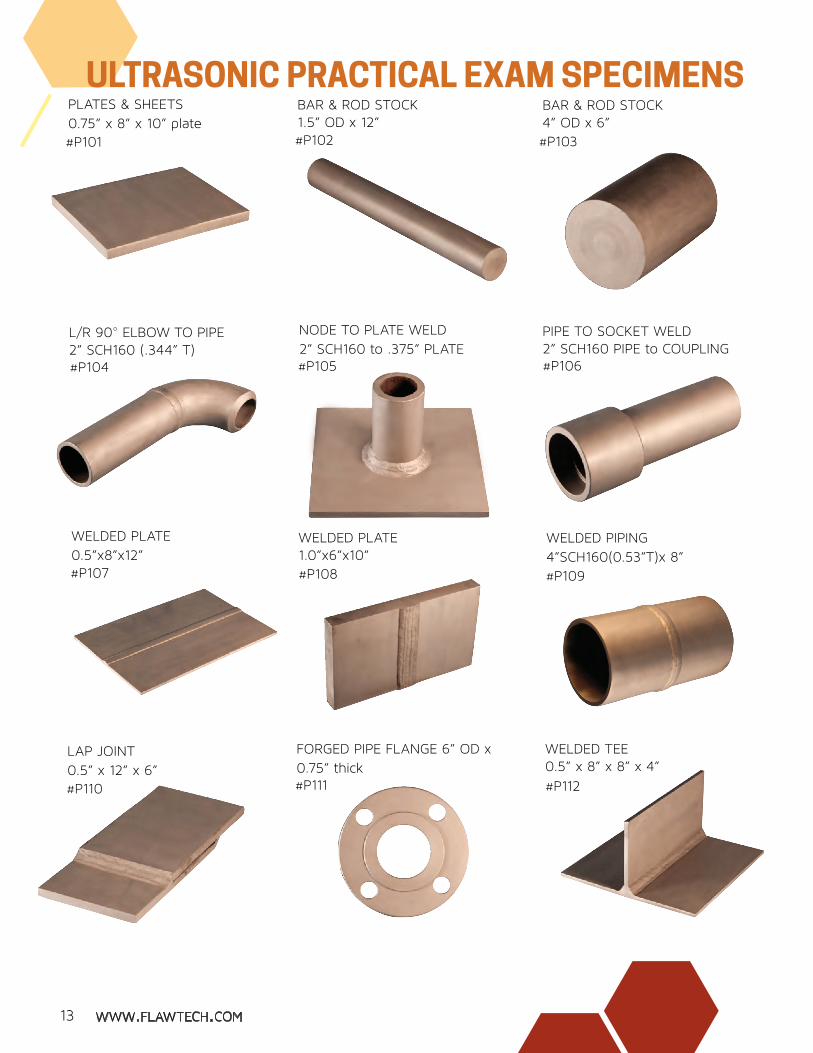
PIPE TO SOCKET WELD 2” SCH160 PIPE to COUPLING#P106
L/R 90° ELBOW TO PIPE2” SCH160 (.344” T) #P104
FORGED PIPE FLANGE 6” OD x 0.75” thick#P111
WELDED PLATE 1.0”x6”x10”#P108
WELDED PLATE 0.5”x8”x12”#P107
LAP JOINT0.5” x 12” x 6”#P110
PLATES & SHEETS0.75” x 8” x 10” plate#P101
NODE TO PLATE WELD 2” SCH160 to .375” PLATE#P105
BAR & ROD STOCK4” OD x 6”#P103
BAR & ROD STOCK1.5” OD x 12”#P102
WELDED PIPING 4”SCH160(0.53”T)x 8”
#P109
#P112
WELDED TEE 0.5” x 8” x 8” x 4”
ULTRASONIC PRACTICAL EXAM SPECIMENS
13

www.flawtech.com flaw manufacturing technology
ULTRASONIC PRACTICAL EXAM SPECIMENS
3 Flaws per specimen
Standard tolerance (+/-) 0.150” (4mm) Custom specimens available
Free carrying case with Purchase of 3+ specimensApplicable for IS09712, PCN & TC - 1A
Document Package with each specimen
“REAL FLAWS” in each specimen
PIPE to SOCKET WELD 2” SCH160 PIPE to COUPLINGMT/PT #P012VT #P212
FORGED EYE HOOK 6” long with 2” eye
FORMED METAL PLATE0.25” x 4”
MT/PT #P008VT #P208
WELDED PIPING4”SCH40(0.25”T)x 8”
WELDED TEE 0.25” x 8” x 8” x 4”
MT/PT #P011VT #P211
CAST FITTING 2.0” to 1.3” reducer, 5” long
MT/PT #P001VT #P201
MACHINED GEAR4.6” diameter x 1.5” boreMT/PT #P010VT #P210
FORGED PIPE FLANGE 6”ODx0.75”thickMT/PT #P009VT #P209
MT/PT #P007VT #P207
WELDED PLATE0.25”x8”x12”
FORGED SHACKLE & PIN4.25” with 0.75” pin
MACHINED SPINDLE 1.75” diameter x 8”
MT/PT #P002VT #P202
MT/PT #P003VT #P203
MT/PT #P004VT #P204
MT/PT #P005VT #P205
MT/PT #P006VT #P206
PRACTICAL EXAM SPECIMEN DETAILS:
Blank specimens available
BOLT & NUT 1.25” OD x 6”
MT / PT & VT PRACTICAL EXAM SPECIMENS
Specimens are carbon steel
14
www.flawtech.com flaw manufacturing technology
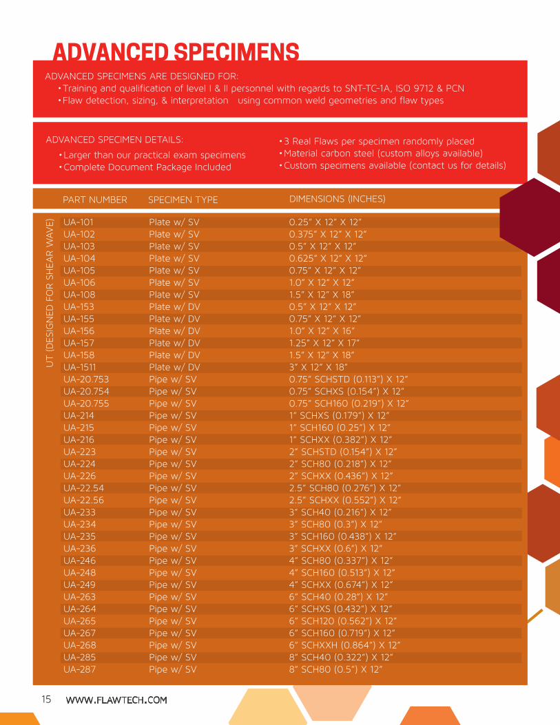
ADVANCED SPECIMENS ARE DESIGNED FOR:• Training and qualification of level I & II personnel with regards to SNT-TC-1A, ISO 9712 & PCN• Flaw detection, sizing, & interpretation using common weld geometries and flaw types
• Larger than our practical exam specimens• Complete Document Package Included
• 3 Real Flaws per specimen randomly placed• Material carbon steel (custom alloys available)• Custom specimens available (contact us for details)
ADVANCED SPECIMEN DETAILS:
ADVANCED SPECIMENSU
T (D
ESIG
NED
FO
R S
HEA
R W
AVE) UA-101
UA-102UA-103UA-104UA-105UA-106UA-108UA-153UA-155UA-156UA-157UA-158UA-1511UA-20.753UA-20.754UA-20.755UA-214UA-215UA-216UA-223UA-224UA-226UA-22.54UA-22.56UA-233UA-234UA-235UA-236UA-246UA-248UA-249UA-263UA-264UA-265UA-267UA-268UA-285UA-287
Plate w/ SVPlate w/ SVPlate w/ SVPlate w/ SVPlate w/ SVPlate w/ SVPlate w/ SVPlate w/ DVPlate w/ DVPlate w/ DVPlate w/ DVPlate w/ DVPlate w/ DVPipe w/ SVPipe w/ SVPipe w/ SVPipe w/ SVPipe w/ SVPipe w/ SVPipe w/ SVPipe w/ SVPipe w/ SVPipe w/ SVPipe w/ SVPipe w/ SVPipe w/ SVPipe w/ SVPipe w/ SVPipe w/ SVPipe w/ SVPipe w/ SVPipe w/ SVPipe w/ SVPipe w/ SVPipe w/ SVPipe w/ SVPipe w/ SVPipe w/ SV
0.25” X 12” X 12”0.375” X 12” X 12”0.5” X 12” X 12”0.625” X 12” X 12”0.75” X 12” X 12”1.0” X 12” X 12”1.5” X 12” X 18”0.5” X 12” X 12”0.75” X 12” X 12”1.0” X 12” X 16”1.25” X 12” X 17”1.5” X 12” X 18”3” X 12” X 18”0.75” SCHSTD (0.113”) X 12”0.75” SCHXS (0.154”) X 12”0.75” SCH160 (0.219”) X 12”1” SCHXS (0.179”) X 12”1” SCH160 (0.25”) X 12”1” SCHXX (0.382”) X 12”2” SCHSTD (0.154”) X 12”2” SCH80 (0.218”) X 12”2” SCHXX (0.436”) X 12”2.5” SCH80 (0.276”) X 12”2.5” SCHXX (0.552”) X 12”3” SCH40 (0.216”) X 12”3” SCH80 (0.3”) X 12”3” SCH160 (0.438”) X 12”3” SCHXX (0.6”) X 12”4” SCH80 (0.337”) X 12”4” SCH160 (0.513”) X 12”4” SCHXX (0.674”) X 12”6” SCH40 (0.28”) X 12”6” SCHXS (0.432”) X 12”6” SCH120 (0.562”) X 12”6” SCH160 (0.719”) X 12”6” SCHXXH (0.864”) X 12”8” SCH40 (0.322”) X 12”8” SCH80 (0.5”) X 12”
SPECIMEN TYPEPART NUMBER DIMENSIONS (INCHES)
15

www.flawtech.com flaw manufacturing technology
RT
8” SCH100 (0.594”) X 12”8” SCH140 (0.812”) X 12”8” SCHSTD (0.906”) X 12”8” w/ 1.5” wall X 12”12” SCHXS (0.5”) X 12”12” SCH120 (1.0”) X 1214” SCH20 (0.312”) X 12”14” SCH40 (0.438”) X 12”14” SCH80 (0.75”) X 12”14” SCH140 (1.25”) X 18”16” SCH160 (1.594”) X 20”0.5” X 8” X 8” X 12” 0.75” X 8” X 8” X 12”1.0” X 8” X 8” X 12”1.0” X 8” X 8” X 12”1.25” X 9” X 9” X 12”1.5” X 10” X 10” X 12”1.25” X 9” X 9” X 12”10” SCH120 (0.844”) X 10”& 1.0” X 20” X 20”8” SCH80 (0.5”) X 10”& 1.0” X 20” X 20”4” SCHXS (0.377”) X 6”& 0.5” X 12” X 12”4” SCH160 (0.531”) X 6”& 0.5” X 12” X 12”8” SCH80 (0.5”) X 10”& 1.0” X 20” X 20”8” SCH80 (0.5”) X 10”& 20” OD X 0.375” wall X 16” X 90°12” SCHXS (0.5”) X 10”& 0.5” X 24” x 24”12” SCH80 (0.688”) X 10”& 0.5” X 24” x 24”
UA-288UA-2810UA-2812UA-2815UA-2127UA-21211UA-2143UA-2145UA-2148UA-21411UA-21611UA-303UA-305UA-306UA-356UA-357UA-358UA 407UA-51010-6
UA-687-6
UA-746-3
UA-748-3
UA-787-6
UA-787-20C
UA-7127-3
UA-7129-3
Pipe w/ SVPipe w/ SVPipe w/ SVPipe w/ SVPipe w/ SVPipe w/ SVPipe w/ SVPipe w/ SVPipe w/ SVPipe w/ SVPipe w/ SVTee w/ SVTee w/ SVTee w/ SVTee w/ DVTee w/ DVTee w/ DVY-Joint (45°)Node& Carrier (Flat)Y-Node (45°)& Carrier (Flat)Nozzle& Carrier (Flat)Nozzle & Carrier (Flat)Nozzle & Carrier (Flat)Nozzle & Carrier (20” OD X 90° Segment)Nozzle& Carrier (Flat) Nozzle & Carrier (Flat)
SPECIMEN TYPEPART NUMBER DIMENSIONS (INCHES)
16
RA-102RA-103RA-105RA-106RA-154RA-155RA-156RA-157RA-223RA-224RA-225RA-226RA-242
Plate w/SVPlate w/SVPlate w/SVPlate w/SVPlate w/DVPlate w/DV Plate w/DVPlate w/DVPipe w/SVPipe w/SVPipe w/SVPipe w/SVPipe w/SV
0.375” x 12” x 12”0.5” x 12” x 12”0.75” x 12” x 12”1.0” x 12” x 16”0.625” x 12” x 12”0.725” x 12” x 12”1.0” x 12” x 16”1.25” x 12” x 17”2” SCH40 (0.154”) X 12”2” SCH80 (0.218”) X 12”2” SCH160 (0.344”) X 12”2” SCHXX X (0.436) 12”4” SCH10 (0.12”) X 12”
www.flawtech.com flaw manufacturing technology
MT/
PT &
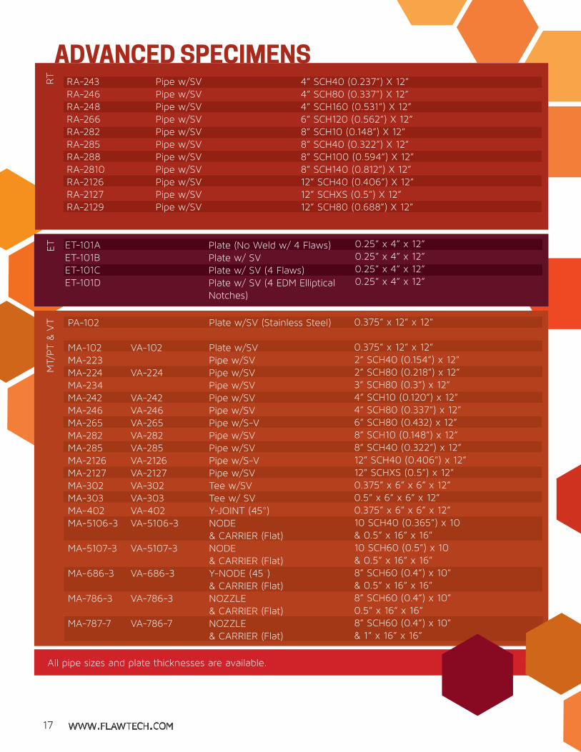
VT PA-102
MA-102MA-223MA-224MA-234MA-242MA-246MA-265MA-282MA-285MA-2126MA-2127MA-302MA-303MA-402MA-5106-3
MA-5107-3
MA-686-3
MA-786-3
MA-787-7
Plate w/SV (Stainless Steel)
Plate w/SVPipe w/SVPipe w/SVPipe w/SVPipe w/SVPipe w/SVPipe w/S-VPipe w/SVPipe w/SVPipe w/S-VPipe w/SVTee w/SVTee w/ SVY-JOINT (45°)NODE & CARRIER (Flat)NODE& CARRIER (Flat)Y-NODE (45°) & CARRIER (Flat)NOZZLE & CARRIER (Flat)NOZZLE & CARRIER (Flat)
0.375” x 12” x 12”
0.375” x 12” x 12”2” SCH40 (0.154”) x 12”2” SCH80 (0.218”) x 12”3” SCH80 (0.3”) x 12”4” SCH10 (0.120”) x 12”4” SCH80 (0.337”) x 12”6” SCH80 (0.432) x 12”8” SCH10 (0.148”) x 12”8” SCH40 (0.322”) x 12”12” SCH40 (0.406”) x 12”12” SCHXS (0.5”) x 12”0.375” x 6” x 6” x 12”0.5” x 6” x 6” x 12”0.375” x 6” x 6” x 12”10 SCH40 (0.365”) x 10 & 0.5” x 16” x 16”10 SCH60 (0.5”) x 10 & 0.5” x 16” x 16”8” SCH60 (0.4”) x 10”& 0.5” x 16” x 16”8” SCH60 (0.4”) x 10” 0.5” x 16” x 16”8” SCH60 (0.4”) x 10” & 1” x 16” x 16”
ET-101AET-101BET-101CET-101D
Plate (No Weld w/ 4 Flaws)Plate w/ SVPlate w/ SV (4 Flaws)Plate w/ SV (4 EDM Elliptical Notches)
0.25” x 4” x 12”0.25” x 4” x 12”0.25” x 4” x 12”0.25” x 4” x 12”
ET
VA-102
VA-224
VA-242VA-246VA-265VA-282VA-285VA-2126VA-2127VA-302VA-303VA-402VA-5106-3
VA-5107-3
VA-686-3
VA-786-3
VA-786-7
All pipe sizes and plate thicknesses are available.
RT
RA-243RA-246RA-248RA-266RA-282RA-285RA-288RA-2810RA-2126RA-2127RA-2129
Pipe w/SVPipe w/SVPipe w/SVPipe w/SVPipe w/SVPipe w/SVPipe w/SVPipe w/SVPipe w/SVPipe w/SVPipe w/SV
4” SCH40 (0.237”) X 12”4” SCH80 (0.337”) X 12”4” SCH160 (0.531”) X 12”6” SCH120 (0.562”) X 12”8” SCH10 (0.148”) X 12”8” SCH40 (0.322”) X 12”8” SCH100 (0.594”) X 12”8” SCH140 (0.812”) X 12”12” SCH40 (0.406”) X 12”12” SCHXS (0.5”) X 12”12” SCH80 (0.688”) X 12”
ADVANCED SPECIMENS
17
www.flawtech.com flaw manufacturing technology
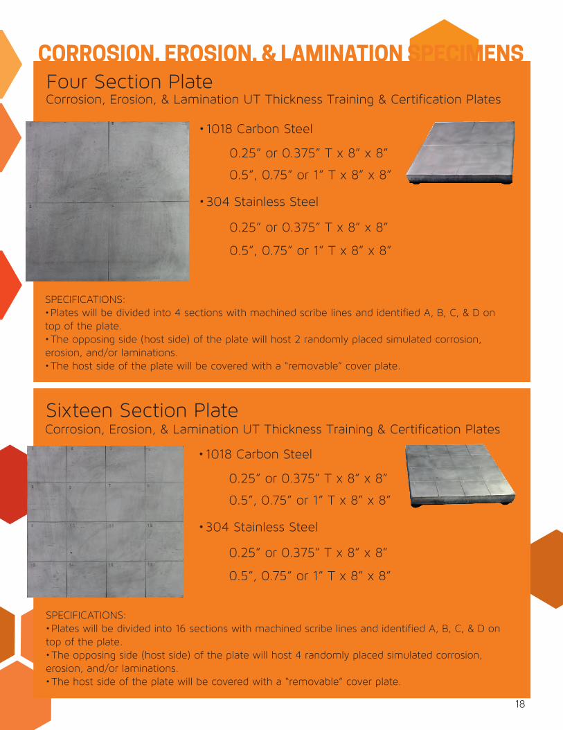
CORROSION, EROSION, & LAMINATION SPECIMENSFour Section Plate
Sixteen Section Plate
•1018 Carbon Steel
0.25” or 0.375” T x 8” x 8”
0.5”, 0.75” or 1” T x 8” x 8”
•304 Stainless Steel
0.25” or 0.375” T x 8” x 8”
0.5”, 0.75” or 1” T x 8” x 8”
Corrosion, Erosion, & Lamination UT Thickness Training & Certification Plates
• 1018 Carbon Steel
0.25” or 0.375” T x 8” x 8”
0.5”, 0.75” or 1” T x 8” x 8”
•304 Stainless Steel
0.25” or 0.375” T x 8” x 8”
0.5”, 0.75” or 1” T x 8” x 8”
Corrosion, Erosion, & Lamination UT Thickness Training & Certification Plates
SPECIFICATIONS: •Plates will be divided into 4 sections with machined scribe lines and identified A, B, C, & D on
top of the plate. •The opposing side (host side) of the plate will host 2 randomly placed simulated corrosion,
erosion, and/or laminations. •The host side of the plate will be covered with a “removable” cover plate.
SPECIFICATIONS: •Plates will be divided into 16 sections with machined scribe lines and identified A, B, C, & D on
top of the plate. •The opposing side (host side) of the plate will host 4 randomly placed simulated corrosion,
erosion, and/or laminations. •The host side of the plate will be covered with a “removable” cover plate.
18
www.flawtech.com flaw manufacturing technology
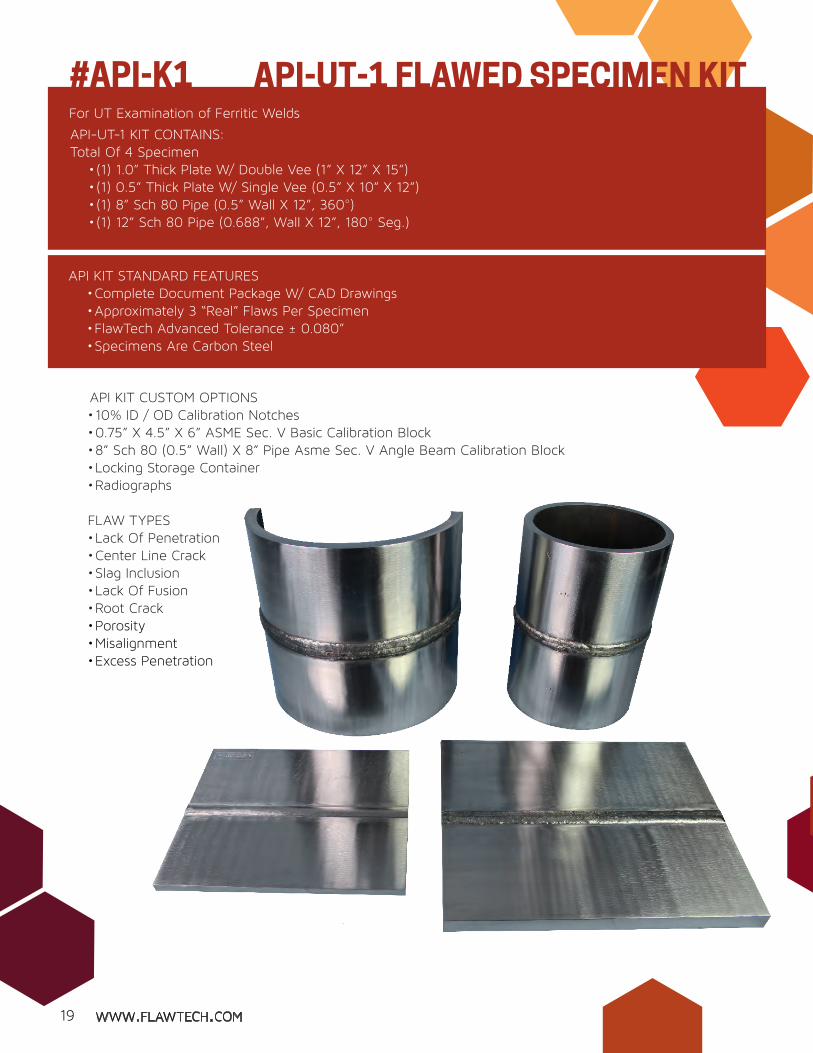
API KIT CUSTOM OPTIONS• 10% ID / OD Calibration Notches• 0.75” X 4.5” X 6” ASME Sec. V Basic Calibration Block• 8” Sch 80 (0.5” Wall) X 8” Pipe Asme Sec. V Angle Beam Calibration Block• Locking Storage Container• Radiographs
FLAW TYPES• Lack Of Penetration • Center Line Crack• Slag Inclusion • Lack Of Fusion• Root Crack• Porosity• Misalignment• Excess Penetration
For UT Examination of Ferritic Welds
API-UT-1 KIT CONTAINS:Total Of 4 Specimen
• (1) 1.0” Thick Plate W/ Double Vee (1” X 12” X 15”)• (1) 0.5” Thick Plate W/ Single Vee (0.5” X 10” X 12”) • (1) 8” Sch 80 Pipe (0.5” Wall X 12”, 360°)• (1) 12” Sch 80 Pipe (0.688”, Wall X 12”, 180° Seg.)
API KIT STANDARD FEATURES• Complete Document Package W/ CAD Drawings • Approximately 3 “Real” Flaws Per Specimen• FlawTech Advanced Tolerance ± 0.080”• Specimens Are Carbon Steel
API-UT-1 FLAWED SPECIMEN KIT#API-K1
19

www.flawtech.com flaw manufacturing technology
API-UT-1 FLAWED SPECIMEN KIT
A Original Kit
Compact version of our API-UT-1 kit
Total of 4 specimen• (1) 1.0” Thick Plate w/ Double Vee (1” x 7.5” x 6”)• (1) 0.5” Thick Plate W/ Single Vee (0.5” X 6” X 5”) • (1) 8” Sch 80 Pipe (0.5” Wall X 6”, 180°)• (1) 12” Sch 80 Pipe (0.688”, Wall X 6”, 90° Seg.)
API MINI KIT STANDARD FEATURES• Complete document package w/ CAD drawings• 3 “real” flaws per specimen• FlawTech advanced tolerance +/- 0.080” • Specimens are carbon steel• Designed for ease of handling and transport• Carrying case 15” x 13” x 10”• Total weight 50lbs
API-UT-MINI KIT#API-MK
API-UT-1 MINI KIT CONTAINS:
Note: Specimens may be too small for some UT search units. If this is a concern please consider our standard API-UT-1 Kit.
20

www.flawtech.com flaw manufacturing technology18A Original Kit
• Each specimen contains 4 flaws / 12 total• API Level “C” Criteria used for flaw design• Flaw accept / reject based on API RP-2X, fig. 45 & 48• UT specimens can be used for technician practice for offshore structures • Flaw acceptability is not determined by ultrasonics
• 90° “T” Connection - 0.75” (T) X 20” (Weld Length) X ~4” X 8”Leg• 45° Connection - 0.75” (T) X 20” (Weld Length) X 4” X 8”Leg• 60° Connection - 0.75” (T) X 20” (Weld Length) X 4” X 8”Leg
API RP-2X PRACTICE SPECIMEN KIT
SPECIMEN DETAILS
Material: 0.75” Carbon Steel PlateSET OF 3 SPECIMENS
CUSTOM OPTIONS AVAILABLE
API RP-2X SPECIMEN KIT#RP2X-K1
Designed in the spirit of API RP-2X, these specimens offer a technician advanced training in UT flaw detection & sizing in unique configurations. This kit is a great tool for conducting practical examinations, as well as preparing technicians for typical industry exams.
THE AP RP-2X EXAM KIT CONTAINS:• 0.75”T Tee Specimen w/ Double Vee Weld• 0. 75”T 60° “Y” Specimen• 1 ”T Plate Specimen w/ Backing Bar• 8” Sch 60 Pipe Specimen, 180° Segment• 10-12 Flaws Total, Including Cracks & Weld Discontinuities
API RP-2X PRACTICE TEST KIT#RP2X-PE
AWS / CWI VISUAL SPECIMEN KIT
21

www.flawtech.com flaw manufacturing technology
API RP-2X SPECIMEN KIT
API RP-2X PRACTICE TEST KIT
A Original Kit
Design Specifications Based On AWS D1.1
KIT CONTAINS 10 SPECIMENS
• Flaws Are Randomly Placed• (4) Tees 4” X 6” X 2” X 0.25”• (4) Plates 4” X 6” X 0.25”• (2) Edge & Lap Joints 4” X 6” X 0.3125”
• Undercut• Crater Crack• Excessive Convexity• Undersize Leg• Cluster Porosity• Arc Strike• Overlap• Longitudinal Crack• Aligned Porosity• Incomplete Penetration• Excessive Reinforcement • Underfill• Concavity• Transverse Crack• Oversize Leg
• 2 Flaws Per Specimen • Flaws Are Randomly Placed • Flaws Are “Border Line” Acceptable or Rejectable• Carbon Steel Specimens• Welding Process - Smaw• Document Package W/ Cad Drawings• “Free” Carrying Case• Designed Specifically For Visual Weld Inspection Training
AWS / CWI VISUAL SPECIMEN KIT# AWS-K1
AWS / CWI KIT DESIGN FEATURES
AWS / CWI KIT FLAWS
22

www.flawtech.com flaw manufacturing technologyA Original Kit
KIT SPECIFICATIONS:
• 1 Carrying Case 6” X 16” X 20,” ~16lbs • All 15 samples fit into one case• Light weight for easy transport• Complete document package includes CAD drawings• 3 to 4 flaws per specimen for a total of 50 weld flaws per kit• Specimens also contain various weld bevels and flame cut edges• (6) Plates• (3) Tee Joints• (6) 180° Pipe Segments
TRAVELER CWI VISUAL TRAINING KIT#TCWI-K1Design Specifications Based On AWS D1.1
Flaws are Intended to be “Borderline” acceptable or rejectable. The end user (CWI) must make that determination.
FlawTech’s new polymer specimen set developed specifically for CWI training and testing. Efficiently designed to provide a maximum number of indications with minimal weight to support the traveling CWI instructor.
(Optional) Weld Size and CAM Gauges
23
www.flawtech.com flaw manufacturing technologyA Original Kit
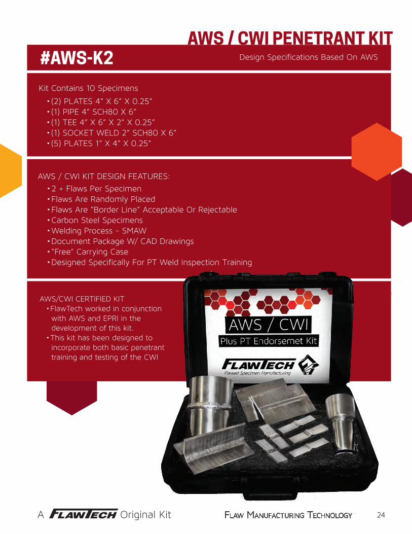
Design Specifications Based On AWS
Kit Contains 10 Specimens
• 2 + Flaws Per Specimen • Flaws Are Randomly Placed • Flaws Are “Border Line” Acceptable Or Rejectable• Carbon Steel Specimens• Welding Process - SMAW• Document Package W/ CAD Drawings• “Free” Carrying Case• Designed Specifically For PT Weld Inspection Training
• (2) PLATES 4” X 6” X 0.25”• (1) PIPE 4” SCH80 X 6”• (1) TEE 4” X 6” X 2” X 0.25”• (1) SOCKET WELD 2” SCH80 X 6”• (5) PLATES 1” X 4” X 0.25”
AWS/CWI CERTIFIED KIT• FlawTech worked in conjunction with AWS and EPRI in the development of this kit.• This kit has been designed to incorporate both basic penetrant training and testing of the CWI
AWS / CWI KIT DESIGN FEATURES:
AWS / CWI PENETRANT KIT#AWS-K2
24
www.flawtech.com flaw manufacturing technology
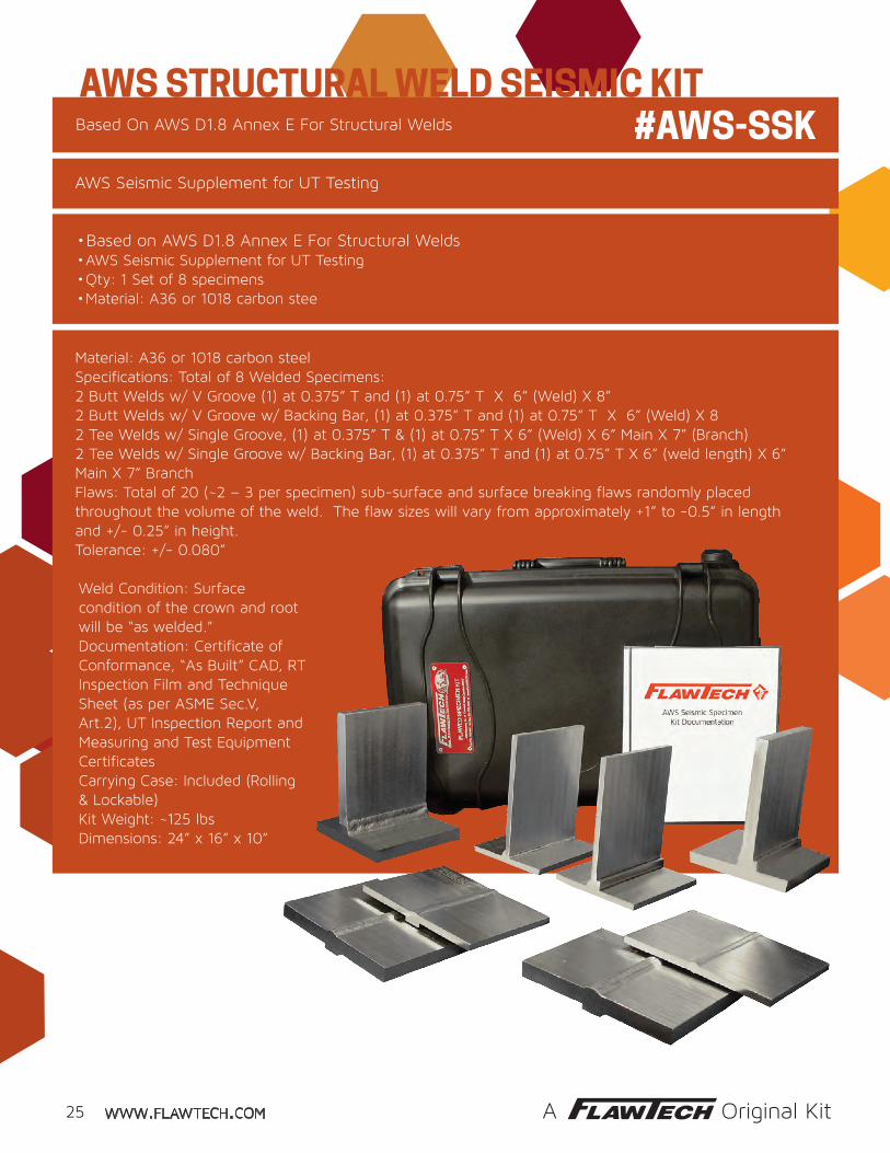
Based On AWS D1.8 Annex E For Structural Welds
AWS Seismic Supplement for UT Testing
• Based on AWS D1.8 Annex E For Structural Welds• AWS Seismic Supplement for UT Testing• Qty: 1 Set of 8 specimens• Material: A36 or 1018 carbon stee
#AWS-SSKAWS STRUCTURAL WELD SEISMIC KIT
A Original Kit
WELD JOINT KITS
25
Material: A36 or 1018 carbon steelSpecifications: Total of 8 Welded Specimens:2 Butt Welds w/ V Groove (1) at 0.375” T and (1) at 0.75” T X 6” (Weld) X 8”2 Butt Welds w/ V Groove w/ Backing Bar, (1) at 0.375” T and (1) at 0.75” T X 6” (Weld) X 8″2 Tee Welds w/ Single Groove, (1) at 0.375” T & (1) at 0.75” T X 6” (Weld) X 6” Main X 7” (Branch)2 Tee Welds w/ Single Groove w/ Backing Bar, (1) at 0.375” T and (1) at 0.75” T X 6” (weld length) X 6” Main X 7” BranchFlaws: Total of 20 (~2 – 3 per specimen) sub-surface and surface breaking flaws randomly placed throughout the volume of the weld. The flaw sizes will vary from approximately +1” to -0.5” in length and +/- 0.25” in height.Tolerance: +/- 0.080”
Weld Condition: Surface condition of the crown and root will be “as welded.”Documentation: Certificate of Conformance, “As Built” CAD, RT Inspection Film and Technique Sheet (as per ASME Sec.V, Art.2), UT Inspection Report and Measuring and Test Equipment CertificatesCarrying Case: Included (Rolling & Lockable)Kit Weight: ~125 lbsDimensions: 24” x 16” x 10”

www.flawtech.com flaw manufacturing technology
SET OF 6 SOCKET WELD SPECIMENS
3 ALLOY OPTIONS • 304 SS #SOC - K1• 316 SS #SOC - K2• 106 CS #SOC - K3
PIPE DIMENSIONS• 0.75” SCH80• 1.0” SCH 80• 2.0” SCH 80
2 SPECIMENS PER PIPE SIZE• (1) Pipe To Socket Coupling• (1) Pipe To 1.5” X 6” X 6” Plate w/ Machined Socket
Pipe to Fitting & Pipe to Vessel Specimens
Specimens are Designed for Ultrasonic Practice Inspection of Pipe To Fitting and Pipe to Vessel Welds
WELD JOINT KITS
A Original Kit
PURCHASE OPTIONS• Kit / Set Contains 6 Specimens• Individually / Purchase 1 Or More
• Customize Your Set / Mix Different Alloys
FLAW SPECIFICATIONS• 2 Flaws Each Specimen• Total Of 12 Real Flaws• Fatigue, Haz Cracks, and Lacks of Fusion
26
www.flawtech.com flaw manufacturing technology
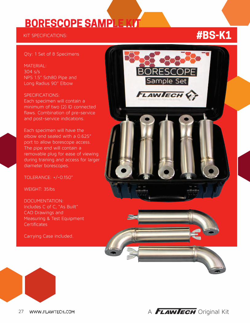
KIT SPECIFICATIONS:
Qty: 1 Set of 8 Specimens
MATERIAL:304 s/sNPS 1.5” Sch80 Pipe and Long Radius 90° Elbow
SPECIFICATIONS:Each specimen will contain a minimum of two (2) ID connected flaws. Combination of pre-service and post-service indications.
Each specimen will have the elbow end sealed with a 0.625” port to allow borescope access.The pipe end will contain a removable plug for ease of viewing during training and access for larger diameter borescopes.
TOLERANCE: +/-0.150”
WEIGHT: 35lbs
DOCUMENTATION:Includes C of C, “As Built” CAD Drawings and Measuring & Test Equipment Certificates
Carrying Case included.
BORESCOPE SAMPLE KIT #BS-K1
27 A Original Kit

www.flawtech.com flaw manufacturing technology
OFFICIALLY LISCENSED BY
EPRI Program 63 Members Receive a Special Discount.
Designed and Manufactured to Replicate Field Removed Specimens
FLAWS / INDICATIONS• Long term overheating/creep• Fire side corrosion (coal)• Toe crack, stress corrosion (stainless) • Soot blower erosion • Fatigue crack (toe) • Maintenance damage• Pitting• Rubbing / Fretting• Chemical cleaning damage (thinning & pitting)
BOILER TUBE DAMAGE KIT
A Original Kit
#EPRI-K1
19 BOILER TUBES:• Representing a complete range of fossil-fired boiler tube failure mechanisms steam and water touched.
TUBE SPECIFICATIONS: • 18 Tubes At 2.5” 0D X 0.25” Wall X 8” Long• 1 Tube At 1.5” X 0.25” Wall X 8” Long
MATERIAL • 17 Tubes are SA513 T5 GR 1020/1026 CS• 1 Tube is 304/304L• 1 Dissimilar metal weld
KIT CONTAINS
• Material flaw (forging lap)• Corrosion fatigue crack• Fly ash erosion, Hydrogen damage• Acid Phosphate corrosion• Caustic gouging• Supercritical waterwall cracking (1.5” 0D tube)• Weld defects (lack of fusion and porosity)• Graphitization
Use This Kit To Assist In The Training And Qualifying Of NDE Technicians To Accurately Identify Specific Boiler Tube Damage Found In Fossil Plants.
Carrying Case: Included (Rolling and Lockable)
28

www.flawtech.com flaw manufacturing technology
8 piece specimen set Contains 20 “real flaws” For Training and Qualification
KIT SPECIFICATIONS• Each specimen contains two to four “real flaws” designed to meet appendix VII specifications.• Specimens are manufactured to FlawTech’s advanced tolerance of +/- 0.080”.• No two specimens are alike. Buy two sets, one for testing and one for training.• Document package includes CAD drawings, certificates of conformance, and NDT reports.• Custom options available such as 10% notches, blank specimens, and the purchase of individual flawed specimens. Contact FlawTech for more details.
2 - WELDED PLATES(1) CARBON STEEL PLATE: #A7-CS-005 (1) STAINLESS PLATE: #A7-SS-0050.5” X 10” X 12”
1 - WELDED PIPE(1) CARBON STEEL PIPE: #A7-CS-100 (180° SEGMENT)10” SCH160 X 12”
1 - WELDED PIPE (1) STAINLESS PIPE: #A7-SS-0606” SCH160 X 12”
1 - WELDED PIPE(1) CARBON STEEL PIPE: #A7-CS-0404” SCH160 X 12”
1 - WELDED PIPE(1) STAINLESS PIPE: #A7-SS-0202” SCH160 X 12”
2 - WELDED PLATES(1) CARBON STEEL PLATE: #A7-CS-010 (1) STAINLESS PLATE: #A7-SS-0101.0” X 10” X 12”
ASME SECTION XI APPENDIX VII KIT
A Original Kit
#A7-K1
29

www.flawtech.com flaw manufacturing technology
2” SCH80 X 24” 360° 4” SCH80 X 24” 360° 6” SCH160 X 24” 360° 12”SCH80s X 24” 360° 24”SCH80s X 24” 120° KIT TOTAL - 5 SPECIMENS
2” SCH80 X 24” 360° 4” SCH80 X 24” 360° 6” SCH160 X 24” 360° 12”SCH80s X 24” 360° 24”SCH80s X 24” 120° KIT TOTAL - 5 SPECIMENS
4” SCH80 X 24” 360° 6” SCH160 X 24” 360° 8” SCH80 X 24” 360° 12”SCH80s X 24” 180° 24”SCH80s X 24” 90° KIT TOTAL - 5 SPECIMENS
UNFLAWED UNITS
ASME BOILER & PRESSURE VESSEL CODE, SECTION XI, APPENDIX VIII, SUPPLEMENTS 2, 3 & 10 KITS
SUPPLEMENT 2 KIT FOR AUSTENITIC PIPING
SUPPLEMENT 3 KIT FOR FERRITIC PIPING
SUPPLEMENT 10 KIT FOR DISSIMILAR METAL WELDS
PIPE SPECIMENDIMENSIONS
FLAWED UNITS
KIT AND FLAW DETAILS:• The kits are manufactured to meet the minimum requirements of ASME, boiler & pressure code, Section XI, Appendix VIII, of Supplements 2, 3 & 10• At least 50% of the cracks will be coincident with fabricated conditions such as: ground & AS-welded crowns, counterbores & weld root conditions. • Flaw depths will range from the 10-30% through the 61 - 100% depth ranges as in ASME section XI, appendix VIII.• All the flaws will be mechanical fatigue or thermal fatigue cracks, with at least 75% of the cracks being thermal fatigue.• Kits made to our critical tolerance ± 0.040” (1MM).• Custom appendix VIII specimens are available.• Contact FlawTech for more details.
#S2-K11349522
1349522
1349522
ASME SECTION XI APPENDIX VIII KITS
#S3-K1
#S10-K1
350 lbs
360 lbs
340 lbs
A Original Kit
1123310
1123310
2234415
30

www.flawtech.com flaw manufacturing technology
DS Block #DS-CB-1DSC Block #DSB-CB-1Metric: #DSB-CB-1M
Resolution Block (RC)#RC-CB-1
DC Block #DC-CB-1
Custom Step Blocks4 Step #4S-CB-15 Step #5S-CB-1
V1/5 (A2)#IIW-V1-1
Type 2 #IIW-T2-1Metric: #IIW-T2-1M
Type 1 #IIW-TI-1Metric: #IIW-T1-1M
ISO 7963 Test Block #2#ISO-TB-2
“PACS” Phased Array Test Block#PACS-1
Set of 19#DA-S19-1
Set of 10#DA-S10-1
Set of 8 #DA-S8-1
Mini Angle Beam Block#MAB-CB-1
V2 (A4) Cal Block#V2-CB-1
ASTW AWS Navships FBH Sensitivity IIW Stepwedges
Angle Beam Phased Array Distance Amplitude Resolution Block
Metric Or Standard Custom
UT CALIBRATION BLOCKS
31
www.flawtech.com flaw manufacturing technology
ASTW AWS Navships FBH Sensitivity IIW Stepwedges
Angle Beam Phased Array Distance Amplitude Resolution Block
Metric Or Standard Custom
Contact FlawTech for all your Standard and Custom Calibration Block Needs.All materials available upon request.
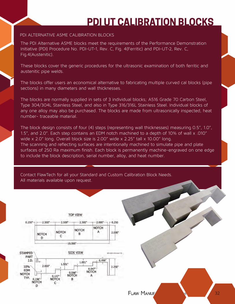
PDI ALTERNATIVE ASME CALIBRATION BLOCKS
The PDI Alternative ASME blocks meet the requirements of the Performance Demonstration Initiative (PDI) Procedure No. PDI-UT-1, Rev. C, Fig. 4(Ferritic) and PDI-UT-2, Rev. C, Fig.4(Austenitic).
These blocks cover the generic procedures for the ultrasonic examination of both ferritic and austenitic pipe welds.
The blocks offer users an economical alternative to fabricating multiple curved cal blocks (pipe sections) in many diameters and wall thicknesses.
The blocks are normally supplied in sets of 3 individual blocks; A516 Grade 70 Carbon Steel, Type 304/304L Stainless Steel, and also in Type 316/316L Stainless Steel. Individual blocks of any one alloy may also be purchased. The blocks are made from ultrasonically inspected, heat number- traceable material.
The block design consists of four (4) steps (representing wall thicknesses) measuring 0.5”, 1.0”, 1.5”, and 2.0”. Each step contains an EDM notch machined to a depth of 10% of wall x .010” wide x 2.0” long. Overall block size is 2.00” wide x 2.25” tall x 10.00” long.The scanning and reflecting surfaces are intentionally machined to simulate pipe and plate surfaces of 250 Ra maximum finish. Each block is permanently machine-engraved on one edge to include the block description, serial number, alloy, and heat number.
PDI UT CALIBRATION BLOCKS
32

www.flawtech.com flaw manufacturing technology
Those listed are just a few of the many ASME calibration standards available. Contact FlawTech for more information.
The block is used for establishment of primary reference responses for UT examination welds. Block contains three (3) DAC side drilled holes at 1.5” deep minimum at diameters between 0.0937” and 0.25” depending on the block thickness (T). Hole locations through the thickness are 1/4, 1/2, and 3/4 T. The block will also two (2) notches measuring 2% (T) deep x 1.0” long minimum. Specification: ASME Section V, Article 4, Figure T-434.2.1. Dimensions: T x 6.25” x 3 (T) minimum. Block is available in normal thicknesses of 0.5”, 1.5”, 3” and 5”.
The basic callibration block for weldments shall be a section of pipe of the same normal size, schedule, heat treatment and material specification as the material being examined. Standard will contain four (4) notches, two (2) longitudinal and two (2) circumferential on both the OD and ID at a target depth of 9.5% of nominal wall thickness and a minimum of 1” long. FlawTech can provide the material or use customer furnished material. In accordance with ASME Sec V, Article 4, Figure T-434.3 (Callibration Block for Pipe.)
ASME SEC. V ANGLE BEAM CALIBRATION BLOCKS
ASME SEC. V BASIC CALLIBRATION BLOCKS
ASME UT CALIBRATION STANDARDS
33 www.flawtech.com
www.flawtech.com flaw manufacturing technologyflaw manufacturing technology
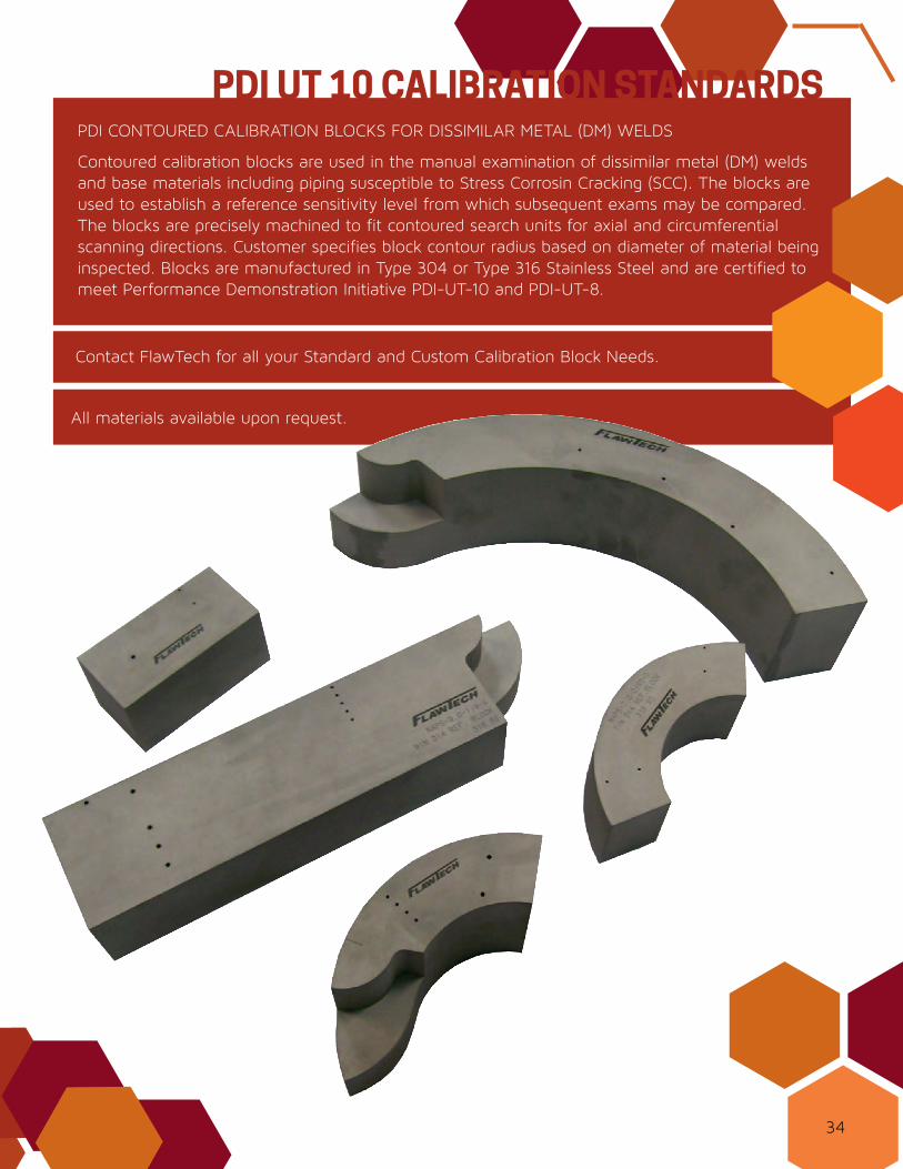
Contoured calibration blocks are used in the manual examination of dissimilar metal (DM) welds and base materials including piping susceptible to Stress Corrosin Cracking (SCC). The blocks are used to establish a reference sensitivity level from which subsequent exams may be compared. The blocks are precisely machined to fit contoured search units for axial and circumferential scanning directions. Customer specifies block contour radius based on diameter of material being inspected. Blocks are manufactured in Type 304 or Type 316 Stainless Steel and are certified to meet Performance Demonstration Initiative PDI-UT-10 and PDI-UT-8.
Contact FlawTech for all your Standard and Custom Calibration Block Needs.
PDI CONTOURED CALIBRATION BLOCKS FOR DISSIMILAR METAL (DM) WELDS
PDI UT 10 CALIBRATION STANDARDS
All materials available upon request.
34
The World Leader in Manufacturing Real FlawsTo Order the Highest Quality Flawed Specimens:
www.FlawTech.comTel: 704.795.4401Fax: 704.795.4403
Vol. 6 - Feb. 2018