Embed Size (px)
Citation preview
ing conditions, not measured by the single-point OTF,should restrict the conditions under which accurateimages can be recovered even in the absence of noise. 1 7
1J. Texereau, "Refiguring the 82-inch McDonald reflector'soptics, " Sky Telescope 28, 345-348 (1964).
2S. P. Worden, C. R. Lynds, and J. W. Harvey, "Recon-structed images of Alpha Orionis using stellar speckle inter-ferometry," J. Opt. Soc. Am. 66, 1234-1246 (1976).
3 A. Labeyrie, "Attainment of diffraction limited resolution inlarge telescopes by Fourier analyzing speckle patterns instar images, "Astron. Astrophys. 6, 85-87 (1970).
4 R. H. T. Bates and P. T. Gough, "Speckle interferometrygives holograms of multiple star systems, "s Astron. Astro-phys. 22, 319-321 (1973).
5 B. L. McGlamery, "Restoration of turbulence-degradedimages," J. Opt. Soc. Am. 57, 293-297 (1967).
6 B. L. McGlamery, NASA Tech. Report No. SP-256, 167(1971).
7K. T. Knox and B. J. Thompson, "Recovery of images fromatmospherically degraded short-exposure photographs,"Astrophys. J. Lett. 193, L45-48 (1974).
8 K. T. Knox, "Image retrieval from astronomical speckle pat-terns," J. Opt. Soc. Am. 66, 1236-39 (1976).
SM. Miller (private communication), see Ref. 17 for details.lLJ. W. Sherman, "A posteriori restoration of atmospherically
degraded images using multiframe imagery, " in Image Pro-
cessing, Proceedings of the S.P.I.E. 74, 249-258 (1976).11D. Korff, "Analysis of a method for obtaining near-diffrac-
tion-limited information in the presence of atmospheric tur-bulence, " J. Opt. Soc. Am. 63, 971-980 (1973).
12 D. P. Karo and A. M. Schneiderman, "Speckle interferom-etry lens-atmosphere MTF measurements," J. Opt. Soc.Am. 66, 1252-1256 (1976).
N3Using C(A) = exp[-2 D(A)], where D(A) is the wave structurefunction given by D(A) =6.88(zro)P/ 3 and this approach to de-fining a correlation scale produces the familiar incident wavecorrelation scale ro. Although in common use, this C(A) cannot be correct since it fails to have the correct (parabolic)form for small A.
iThe MTF corrected for the known low-frequency telescopeMTF does follow the Fried theory out to nearly the seeing-limited spatial frequency. We weight the lowest-frequencypoints most strongly in determining the Diro value which bestfits the short-exposure theory to the data.
i5 D. L. Fried, "Optical resolution through a randomly inhomo-geneous medium for very long and very short exposures, " J.Opt. Soc. Am. 56, 1372-79 (1966).
16 D. Korff, G. Dryden, and M. G. Miller, "Information re-trieval from atmospheric induced speckle patterns, "d OpticsCommun. 5, 187-192 (1972).
17D. P. Karo and A. M. Schneiderman, "Image reconstructionin speckle interferometry, "s Imaging in Astronomy TechnicalDigest, ThC4-l1,3 OSA Topical Meeting, June 18-21, 1975,Cambridge, Massachusetts.
The vulnerability of speckle photography to lens aberrationsKarl A. Stetson
Instrumentation Laboratory (81), United Technologies Research Center, East Hartford, Connecticut 06108(Received 25 April 1977)
It is experimentally demonstrated that lens aberrations can have detrimental effects in specklephotography. These effects include not only loss of speckle correlations and subsequent halo fringes, but alsodistortion of the halo fringes that can lead to false information about object motion.
INTRODUCTION
Because the size and texture of speckles formed in thecoherent image of a diffusely reflecting object are gen-erally unaffected by the aberrations of the imagingsystem, it is assumed by most authors that they do notplay a role in the measurement of object displacementsby speckle photography. Speckle photography, in itssimplest form, involves recording two exposures of anobject, lit by laser light, before and after some defor-mation. The simplest method of extracting the trans-verse displacement from such a photographic transpar-ency (or specklegram) is to illuminate a small regionof it with a converging beam of laser light. In the planewhere the beam comes to focus, a halo of light willappear that has been diffracted away from the point offocus of the converging beam. Within the halo may befound fringes, similar to Young's fringes, that resultfrom the displacement of what are otherwise identicalspeckle patterns corresponding to the two exposures.If the surface is in focus, the speckle patterns in theimage move as if attached to the object surface. Fur-ther details of the subject are available from reviewarticles in the literature. 1,2
1587 J. Opt. Soc. Am., Vol. 67, No. II, November 1977
As early as 1972, however, Ennos recognized thatlens aberrations could play a limiting role in makingmeasurements with speckle photography, and publishedsome data with regard to in-plane rotation. 3 His wordsof caution cannot be said to have launched any extensiveinvestigation into this effect, however. There wassome surprise, therefore, when certain of this author'scolleagues, at Pratt and Whitney Aircraft, obtainedcurved and interrupted halo fringes as a result of oneof their more difficult applications of speckle photog-raphy. Because their lenses were being used well offaxis, there was reason to expect severe lens aberra-tions, and therefore, an experiment was conceived toconfirm their potential effect in speckle photography.
HUERISTIC EXPLANATION
Light is diffracted to a particular region of aspeckle halo by speckle structure in the specklegramformed by recording interference of all those ray pairsin the lens aperture with a given angular orientationand a given spacing. This is illustrated in Fig. 1which shows [Fig. 1(a)] a speckle halo (assumed to bethe same distance from the specklegram as the orig-
Copyright © 1977 by the Optical Society of America 1587
+1
(a) (b)
FIG. 1. Speckle halo and its corresponding lens aperture.The photographic structure in the specklegram that diffractslight to the points ± 1 in (a) results from the recording of inter-ference of ray pairs such as those indicated in (b).
inal lens), with the two arrows denoting light diffract-ed away from the zero order (the central spot) topoints + 1 and - 1. Figure 1(b) shows the lens aper-ture, and the three double arrows indicate three raypairs of the ensemble whose interference could create
i
(b)
ka)
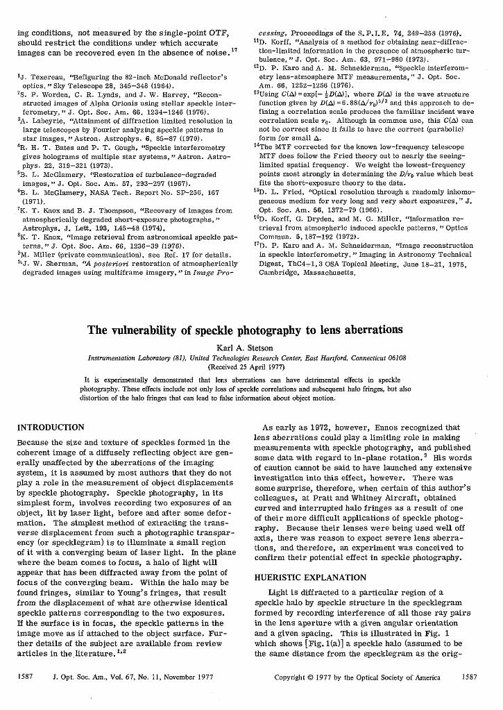
FIG. 2. Speckle halos obtained from a specldegram recorded by a well-corrected copy lens at 1: 1 magnification. The objecthas moved helically between exposures. Four halos from four regions in the field of view are shown: (a) top center, (b) top right,(c) center, and (d) center right.
1588 J. Opt. Soc. Am., Vol. 67, No. I 1, November 1977
a speckle structure in the specklegram that could dif-fract light to the points ± 1. The separation of the endpoint of each ray pair in the lens aperture is the sameas the distance from the center of the speckle halo tothe points ± 1, and the angular orientation of the pairsmatches that of the points ± 1. The shaded region ofthe lens aperture shows the area from which suchlens pairs can originate. Clearly, the light diffractedto the perimeter of the halo results from interferingray pairs from two small regions near the edges of thelens aperture, i. e., peripheral rays.
Let us trace rays backward from a single point in theimage plane to where they come to focus near the sur-face of the object. In the case of spherical aberration,it is well known that peripheral rays may focus at apoint in front of the object surface when central raysfocus at the object surface. The fringes that form inthe halo of a double-exposure specklegram result frommotions of the speckles in the image between the twoexposures. Thus, if the apparent speckles imaged byan optical system focused in front of an object surfacemove in a different direction from those formed whenthe system is focused on the object surface, we mayexpect that a specklegram recorded with a spherically
Karl A. Stetson 1588
Wa)
kc) k0)
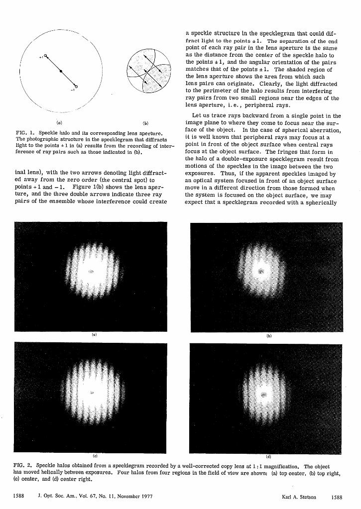
FIG. 3. Speckle halos obtained from a specklegram recorded by a normal camera objective at 1 :1 magnification. Object motionis the same as in the previous figure, and a, b, c, and d denote the same regions of the field of view.
aberrated lens will exhibit halo fringes whose orienta-tion at the edge of the halo is different from those atthe center, i. e., curved halo fringes. If ray pairs areskew in the object space, i. e., do not cross, or if raypairs cross at different planes in the object space, de-pending upon what portion of the lens aperture theyoriginate from, we may expect a loss in contrast in thehalo fringes for certain regions of the halo.
From theoretical work on the effect of defocusing inspeckle photography, it can be shown that if an objectsurface is given a helical motion, the speckle displace-ments will vary in direction as a function of focal plane.Only at the object surface will they move along the axisof the helix. In front of the surface, the tilt will addan orthogonal component of motion and behind it, willsubtract the same component. The further from theobject surface, the larger the orthogonal component.A specklegram recorded of a helically moving objectwould, therefore, be ideal for demonstrating the effectof lens aberrations on speckle photography.
EXPERIMENT
We selected a hollow cylinder, with 38 mm internaldiameter, and machined a slot in its wall at 450 to the
1589 J. Opt. Soc. Am., Vol. 67, No. I l, November 1977
axis. We then machined a cylindrical shaft so that itwould move smoothly within the slotted cylinder andfixed a pin into it through the slot. The cylindricalshaft was thus constrained to move like a screw. A flataluminum surface was fixed to the end of the shaft bya bracket so that its plane contained the axis of thecylinders. The surface was sand blasted and etched toobtain a matte texture. It was set normal to the axisof a 35 mm camera at the proper distance for imagingat 1: 1 magnification with a well-corrected CRT lens(Ilex No. 5007, 56 mm focal length, f/1. 9). Alterna-tively, the surface could be imaged with the normallens for the camera (Fujica ST701, focal length 55 mm,f/l. 8). (The normal camera lens is, of course, illsuited to forming images at 1 : 1 magnification.)
Two double-exposure specklegrams were recorded(one with the Ilex lens and one with the Fujica lens),and between the two exposures of each, the object wasgiven a suitable displacement so as to generate halofringes. The specklegrams were recorded on KodakS0253 holographic film, and a He-Ne laser was usedfor illumination. The specklegrams were illuminatedwith a narrow, converging beam of light; the halos wereprojected onto a translucent screen and photographed.Figures 2 and 3 show halos obtained from four regions
Karl A. Stetson 1589
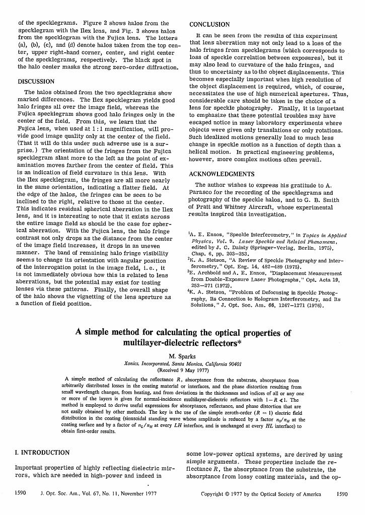
of the specklegrams. Figure 2 shows halos from thespecklegram with the Ilex lens, and Fig. 3 shows halosfrom the specklegram with the Fujica lens. The letters(a), (b), (c), and (d) denote halos taken from the top cen-ter, upper right-hand corner, center, and right centerof the specklegrams, respectively. The black spot inthe halo center masks the strong zero-order diffraction.
DISCUSSION
The halos obtained from the two specklegrams showmarked differences. The Ilex specklegram yields goodhalo fringes all over the image field, whereas theFujica specklegram shows good halo fringes only in thecenter of the field. From this, we learn that theFujica lens, when used at 1 :1 magnification, will pro-vide good image quality only at the center of the field.(That it will do this under such adverse use is a sur-prise..) The orientation of the fringes from the Fujicaspecklegram slant more to the left as the point of ex-amination moves farther from the center of field. Thisis an indication of field curvature in this lens. Withthe Ilex specklegram, the fringes are all more nearlyin the same orientation, indicating a flatter field. Atthe edge of the halos, the fringes can be seen to beinclined to the right, relative to those at the center.This indicates residual spherical aberration in the Ilexlens, and it is interesting to note that it exists acrossthe entire image field as should be the case for spher-ical aberration. With the Fujica lens, the halo fringecontrast not only drops as the distance from the centerof the image field increases, it drops in an unevenmanner. The band of remaining halo fringe visibilityseems to change its orientation with angular positionof the interrogation point in the image field, i. e., itis not immediately obvious how this is related to lensaberrations, but the potential may exist for testinglenses via these patterns. Finally, the overall shapeof the halo shows the vignetting of the lens aperture asa function of field position.
CONCLUSION
It can be seen from the results of this experimentthat lens aberration may not only lead to a loss of thehalo fringes from specklegrams (which corresponds toloss of speckle correlation between exposures), but itmay also lead to curvature of the halo fringes, andthus to uncertainty as to the object displacements. Thisbecomes especially important when high resolution ofthe object displacement is required, which, of course,necessitates the use of high numerical apertures. Thus,considerable care should be taken in the choice of alens for speckle photography. Finally, it is importantto emphasize that these potential troubles may haveescaped notice in many laboratory experiments whereobjects were given only translations or only rotations.Such idealized motions generally lead to much lesschange in speckle motion as a function of depth than ahelical motion. In practical engineering problems,however, more complex motions often prevail.
ACKNOWLEDGMENTS
The author wishes to express his gratitude to A.Parasco for the recording of the specklegrams andphotography of the speckle halos, and to G. B. Smithof Pratt and Whitney Aircraft, whose experimentalresults inspired this investigation.
'A. E. Ennos, "Speckle Interferometry," in Topics in AppliedPhysics, Vol. 9. Laser Speckle and Related Phenomena,edited by J. C. Dainty (Springer-Verlag, Berlin, 1975),Chap. 6, pp. 203-253.
2K. A. Stetson, "A Review of Speckle Photography and Inter-ferometry," Opt. Eng. 14, 482-489 (1975).
3 E. Archbold and A. E. Ennos, "Displacement Measurementfrom Double-Exposure Laser Photographs," Opt. Acta 19,253-271 (1972).
4K. A. Stetson, "Problem of Defocusing in Speckle Photog-raphy, Its Connection to Hologram Interferometry, and ItsSolutions, " J. Opt. Soc. Am. 66, 1267-1271 (1976).
A simple method for calculating the optical properties ofmultilayer-dielectric reflectors*
M. SparksXonics, Incorporated, Santa Monica, California 90401
(Received 9 May 1977)
A simple method of calculating the reflectance R, absorptance from the substrate, absorptance fromarbitrarily distributed losses in the coating material or interfaces, and the phase distortion resulting fromsmall wavelength changes, from heating, and from deviations in the thicknesses and indices of all or any oneor more of the layers is given for normal-incidence multilayer-dielectric reflectors with 1 - R e, 1. Themethod is employed to derive useful expressions for absorptance, reflectance, and phase distortion that arenot easily obtained by other methods. The key is the use of the simple zeroth-order (R = 1) electric fielddistribution in the coating (sinusoidal standing wave whose amplitude is reduced by a factor no/nH at thecoating surface and by a factor of nL/nH at every LH interface, and is unchanged at every HL interface) toobtain first-order results.
I. INTRODUCTION
Important properties of highly reflecting dielectric mir-rors, which are needed in high-power and indeed in
1590 J. Opt. Soc. Am., Vol. 67, No. I l, November 1977
some low-power optical systems, are derived by usingsimple arguments. These properties include the re-flectance R, the absorptance from the substrate, theabsorptance from lossy coating materials, and the op-
Copyright © 1977 by the Optical Society of America 1590