Embed Size (px)
Citation preview

TheVideoEncyclopedia
ofPhysicsDemonstrations™
Explanatory Material By: Dr. Richard E. BergUniversity of Maryland
Scripts By: Brett CarrollUniversity of Washington
Equipment List By: John A. DavisUniversity of Washington
Editor: Rosemary Wellner
Graphic Design: Wade Lageose/Art Hotel
Typography: Malcolm Kirton
Our special thanks to Jearl Walker for his assistance during the production ofthis series; to Gerhard Salinger for his support and encouragement during theproduction of this series; and to Joan Abend, without whom all this would nothave been possible.
We also wish to acknowledge the hard work of Laura Cepio, David DeSalvo,Michael Glotzer, Elizabeth Prescott and Maria Ysmael.
This material is based upon work supported by The National Science Foundation under Grant Number MDR-9150092.
© The Education Group & Associates, 1992.
ISBN 1-881389-00-6
All rights reserved. No part of this publication may be reproduced or transmitted in any form or by any means, electronic or mechanical, including photocopy, recording, or any informationstorage and retrieval system, without permission in writing from the publisher.
Requests for permission to make copies of any part of the work should be mailed to: The Education Group, 1235 Sunset Plaza Drive, Los Angeles, CA 90069.
D I S C N I N E
Chapter 20 Resonance
Demo 09-01 Bowling Ball Pendulum Resonance..............................6
Demo 09-02 Resonant Driven Pendula ..............................................8
Demo 09-03 Driven Spring and Weight ...........................................10
Demo 09-04 Pump Pendulum ..........................................................12
Demo 09-05 Reed Tachometer .........................................................14
Demo 09-06 Glass Breaking with Sound .........................................16
Demo 09-07 Coupled Pendula..........................................................18
Demo 09-08 Wilberforce Pendulum.................................................20
Chapter 21 Mechanical Waves
Demo 09-09 Wave on Rope ..............................................................24
Demo 09-10 Pulse on Moving Chain................................................26
Demo 09-11 Tension Dependence of Wave Speed.........................28
Demo 09-12 Torsional Waves ...........................................................30
Demo 09-13 Wave Speed ..................................................................32
Demo 09-14 Longitudinal Wave Model ............................................34
Demo 09-15 Longitudinal Slinky Waves...........................................36
Demo 09-16 Wave Superposition .....................................................38
Demo 09-17 Reflection of Waves......................................................40
Demo 09-18 Spring Wave Reflection................................................42
Demo 09-19 Wave Coupling .............................................................44
Demo 09-20 Refraction of Water Waves...........................................46
Demo 09-21 Single Slit Diffraction of Water Waves.........................48
Demo 09-22 Double Slit Interference of Water Waves....................50
Demo 09-23 Moire Pattern ................................................................52
Chapter 22 Standing Waves
Demo 09-24 Longitudinal Standing Waves.......................................56
Demo 09-25 Slinky Standing Waves .................................................58
Demo 09-26 Standing Waves ............................................................60
Demo 09-27 Three Tensions Standing Waves..................................62
Demo 09-28 Rubber Tube Standing Waves .....................................64
Demo 09-29 Drumhead.....................................................................66
Demo 09-30 Chladni Plates...............................................................68

5
C H A P T E R 2 0
R E S O N A N C E
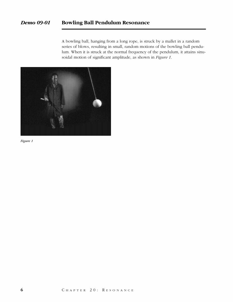
A bowling ball, hanging from a long rope, is struck by a mallet in a randomseries of blows, resulting in small, random motions of the bowling ball pendu-lum. When it is struck at the normal frequency of the pendulum, it attains sinu-soidal motion of significant amplitude, as shown in Figure 1.
Demo 09-01 Bowling Ball Pendulum Resonance
6 C H A P T E R 2 0 : R E S O N A N C E
Figure 1
This bowling ball pendulum will be used to demonstrate resonance.
The pendulum swings with a natural frequency of about one swing every twoseconds.
We’ll drive it by striking it with a rubber mallet.
First we’ll drive the pendulum by striking it repeatedly at short intervals. Evenafter many blows, the pendulum isn’t moving very far.
But if we change the striking frequency to the natural frequency of the pendu-lum, the amplitude increases with each blow of the mallet.
Bowling Ball Pendulum Resonance /Script Demo 09-01
C H A P T E R 2 0 : R E S O N A N C E 7
Equipment
1. Bowling ball pendulum.2. Suspension system as described earlier.3. Rubber mallet.
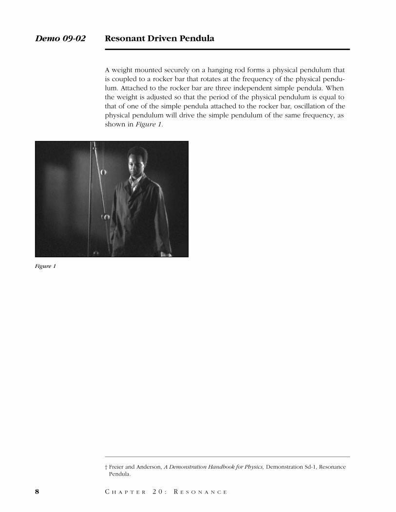
A weight mounted securely on a hanging rod forms a physical pendulum thatis coupled to a rocker bar that rotates at the frequency of the physical pendu-lum. Attached to the rocker bar are three independent simple pendula. Whenthe weight is adjusted so that the period of the physical pendulum is equal tothat of one of the simple pendula attached to the rocker bar, oscillation of thephysical pendulum will drive the simple pendulum of the same frequency, asshown in Figure 1.
Demo 09-02 Resonant Driven Pendula
8 C H A P T E R 2 0 : R E S O N A N C E
Figure 1
† Freier and Anderson, A Demonstration Handbook for Physics, Demonstration Sd-1, ResonancePendula.
This physical pendulum drives a rocker bar, which in turn drives three simplependula hanging from the bar.
The driving frequency can be changed by moving a weight on the physicalpendulum.
The weight is first adjusted so that the driving frequency is equal to the naturalfrequency of the longest pendulum.
If the three pendula are initially stationary, only the longest pendulumresponds strongly.
The weight is now adjusted so that the driving frequency matches the fre-quency of the middle pendulum.
Notice the strong response of the middle pendulum, and the different phaselags between the driver pendulum and each of the three simple pendula.
Resonant Driven Pendula / Script Demo 09-02
C H A P T E R 2 0 : R E S O N A N C E 9
Equipment
1. Massive physical pendulum firmly fixed to a rocker bar with a bob whose position canquickly and easily change with a thumb screw.
2. Support system.3. Three pendula with bifilar suspension of differing lengths, each independently supported
from the rocker bar.
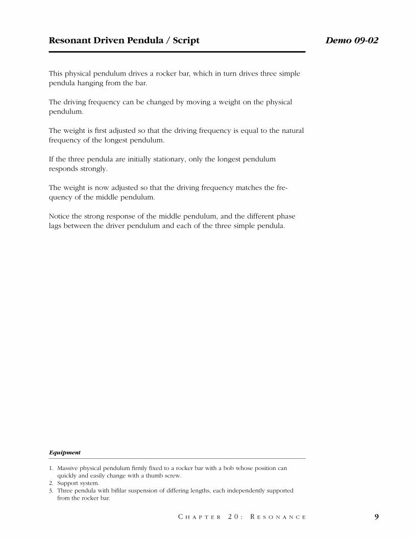
A mass on the end of a spring is driven by a mechanical oscillator, as shown inFigure 1, at frequencies below, at, and above the resonant frequency of themass on the spring.† The resulting amplitude of vibration of the mass on thespring and the phase of the oscillation of the mass relative to that of the dri-ving force can be observed on the video.‡
Demo 09-03 Driven Spring and Weight
10 C H A P T E R 2 0 : R E S O N A N C E
Figure 1
† Sutton, Demonstration Experiments in Physics, Demonstration S-13, Forced Vibrations andResonance.
‡ Sutton, Demonstration Experiments in Physics, Demonstration S-14, Forced Vibrations andResonance—Phase Relations.
This spring and weight hang from a driver whose frequency can be adjustedwith this control.
We’ll increase the driving frequency slowly and watch the effect on the motionof the weight.
At low frequencies, the mass moves very little.
As the frequency increases, the amplitude of oscillation increases until themass strikes the table. The weight is now lagging behind the driver, which ismoving at the resonant frequency of the spring and weight.
When the frequency is increased further, the amplitude of oscillationdecreases.
Driven Spring and Weight / Script Demo 09-03
C H A P T E R 2 0 : R E S O N A N C E 11
Equipment
1. Spring and weight.2. Variable speed, motor-driven suspension point and support assembly.3. Motor speed control.
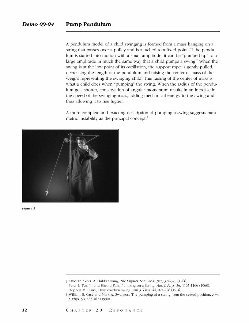
A pendulum model of a child swinging is formed from a mass hanging on astring that passes over a pulley and is attached to a fixed point. If the pendu-lum is started into motion with a small amplitude, it can be “pumped up” to alarge amplitude in much the same way that a child pumps a swing.† When theswing is at the low point of its oscillation, the support rope is gently pulled,decreasing the length of the pendulum and raising the center of mass of theweight representing the swinging child. This raising of the center of mass iswhat a child does when “pumping” the swing. When the radius of the pendu-lum gets shorter, conservation of angular momentum results in an increase inthe speed of the swinging mass, adding mechanical energy to the swing andthus allowing it to rise higher.
A more complete and exacting description of pumping a swing suggests para-metric instability as the principal concept.‡
Demo 09-04 Pump Pendulum
12 C H A P T E R 2 0 : R E S O N A N C E
† Little Thinkers: A Child’s Swing, The Physics Teacher 4, 307, 374-375 (1966). Peter L. Tea, Jr. and Harold Falk, Pumping on a Swing, Am. J. Phys. 36, 1165-1166 (1968). Stephen M. Curry, How children swing, Am. J. Phys. 44, 924-926 (1976).
‡ William B. Case and Mark A. Swanson, The pumping of a swing from the seated position, Am.J. Phys. 58, 463-467 (1990).
Figure 1
These children know how to pump a swing so that the swing goes higher andhigher with each pass. But how is it actually done?
This demonstration will use a pendulum on a string in place of a swing toshow how it is achieved.
The string of the pendulum passes over a pulley so that the weight can beraised or lowered slightly. If the pendulum is set swinging with a small ampli-tude, we can pump it up by pulling up on the string each time the weight getsto the bottom and releasing it as it reaches the top.
We do the same on a swing by raising our legs and pulling back on the ropesas we pass the bottom, then letting go at the top of each swing.
Pump Pendulum / Script Demo 09-04
C H A P T E R 2 0 : R E S O N A N C E 13
Equipment
1. Tall ring stand.2. Clamp and cross bar.3. Clamp and bearing pulley.4. Weight.5. Long piece of string.
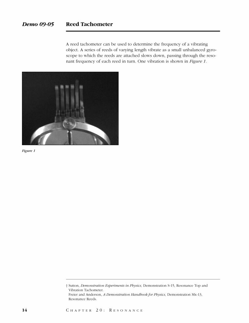
A reed tachometer can be used to determine the frequency of a vibratingobject. A series of reeds of varying length vibrate as a small unbalanced gyro-scope to which the reeds are attached slows down, passing through the reso-nant frequency of each reed in turn. One vibration is shown in Figure 1.
Demo 09-05 Reed Tachometer
14 C H A P T E R 2 0 : R E S O N A N C E
Figure 1
† Sutton, Demonstration Experiments in Physics, Demonstration S-15, Resonance Top andVibration Tachometer. Freier and Anderson, A Demonstration Handbook for Physics, Demonstration Mx-13,Resonance Reeds.
This reed tachometer consists of a group of metal reeds of varying lengthsattached to a gyroscope. The reeds have different frequencies of oscillation.The gyroscope wheel is unbalanced so that it vibrates slightly when it spins.
We’ll spin the gyroscope and watch what happens to the reeds as the gyro-scope slows down and the vibration frequency changes from high to low.
Reed Tachometer / Script Demo 09-05
C H A P T E R 2 0 : R E S O N A N C E 15
Equipment
1. Reed tachometer.2. Motor with rubber covered start-up disc.3. Clamps.
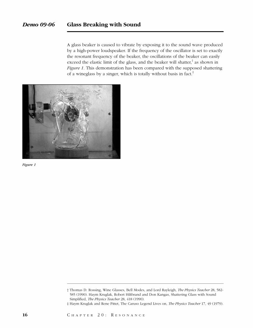
A glass beaker is caused to vibrate by exposing it to the sound wave producedby a high-power loudspeaker. If the frequency of the oscillator is set to exactlythe resonant frequency of the beaker, the oscillations of the beaker can easilyexceed the elastic limit of the glass, and the beaker will shatter,† as shown inFigure 1. This demonstration has been compared with the supposed shatteringof a wineglass by a singer, which is totally without basis in fact.‡
Demo 09-06 Glass Breaking with Sound
16 C H A P T E R 2 0 : R E S O N A N C E
Figure 1
† Thomas D. Rossing, Wine Glasses, Bell Modes, and Lord Rayleigh, The Physics Teacher 28, 582-585 (1990). Haym Kruglak, Robert Hiltbrand and Don Kangas, Shattering Glass with SoundSimplified, The Physics Teacher 28, 418 (1990).
‡ Haym Kruglak and Rene Pittet, The Caruso Legend Lives on, The Physics Teacher 17, 49 (1979).
We will demonstrate resonance by breaking a glass beaker with a sound wave.
This beaker has a natural oscillation which can be produced by gently tappingits brim. We create a resonance by exposing the beaker to a sound wave of thesame frequency.
For this demonstration we use a stable oscillator,
a power amplifier,
and a horn driver which can handle a large amount of power.
The beaker is positioned on a foam rubber pedestal in front of the hole fromwhich the sound emerges. The sound wave emitted by the vibrating beaker ispicked up by the microphone to the left of the beaker and displayed on theoscilloscope, the oscilloscope is triggered by the signal from the oscillator, butdisplays the signal emitted by the beaker, so that both the amplitude increaseand the phase shift can be observed as the frequency is tuned through reso-nance.
The frequency of the oscillator has now been set to the natural frequency ofthe beaker.
Using a stroboscope, the oscillations of the brim of the beaker can be viewedfrom above.
Returning to a front view of the beaker, we now increase the amplitude of thesound wave until the oscillation of the beaker exceeds its elastic limit.
Glass Breaking with Sound / Script Demo 09-06
C H A P T E R 2 0 : R E S O N A N C E 17
Equipment
1. Highly stable audio oscillator.2. Power amplifier.3. Horn driver.4. Support system for number 3 and a microphone.5. Foam rubber pad.6. Oscilloscope.7. Strobe light.8. Safety shield.
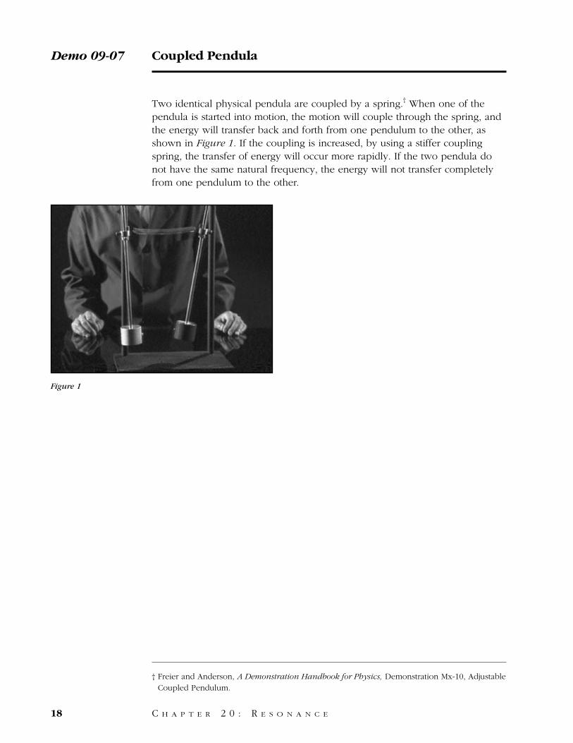
Two identical physical pendula are coupled by a spring.† When one of thependula is started into motion, the motion will couple through the spring, andthe energy will transfer back and forth from one pendulum to the other, asshown in Figure 1. If the coupling is increased, by using a stiffer couplingspring, the transfer of energy will occur more rapidly. If the two pendula donot have the same natural frequency, the energy will not transfer completelyfrom one pendulum to the other.
Demo 09-07 Coupled Pendula
18 C H A P T E R 2 0 : R E S O N A N C E
Figure 1
† Freier and Anderson, A Demonstration Handbook for Physics, Demonstration Mx-10, AdjustableCoupled Pendulum.
This pair of physical pendula have the same period. If we connect the pendulatogether with a light spring and set one in motion, the second pendulum alsobegins to move.
Soon both pendula have nearly equal motions.
Now the second pendulum has all the energy and the first pendulum hasnearly stopped.
The energy has now gone full cycle, with the first pendulum in full motion andthe second at rest.
If we connect the two pendula with a stiffer spring, the energy is exchangedmuch more quickly.
If we change the period of one of the pendula by moving a weight, the energyno longer passes completely from one pendulum to the other.
Coupled Pendula / Script Demo 09-07
C H A P T E R 2 0 : R E S O N A N C E 19
Equipment
1. Two physical pendula whose identical bobs can have their position adjusted and which aresupported from low friction-bearing systems.
2. Supporting system.3. Hooks on both pendula near their midpoints.4. Several springs with varying spring constants.
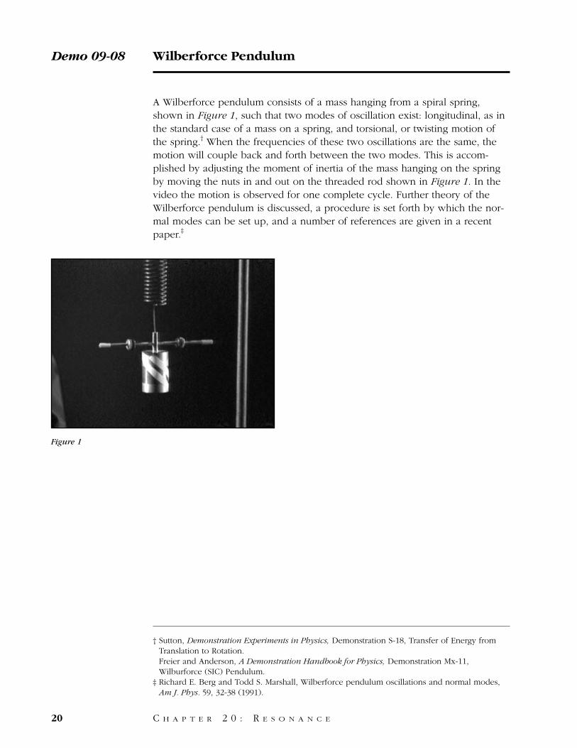
A Wilberforce pendulum consists of a mass hanging from a spiral spring,shown in Figure 1, such that two modes of oscillation exist: longitudinal, as inthe standard case of a mass on a spring, and torsional, or twisting motion ofthe spring.† When the frequencies of these two oscillations are the same, themotion will couple back and forth between the two modes. This is accom-plished by adjusting the moment of inertia of the mass hanging on the springby moving the nuts in and out on the threaded rod shown in Figure 1. In thevideo the motion is observed for one complete cycle. Further theory of theWilberforce pendulum is discussed, a procedure is set forth by which the nor-mal modes can be set up, and a number of references are given in a recentpaper.‡
Demo 09-08 Wilberforce Pendulum
20 C H A P T E R 2 0 : R E S O N A N C E
Figure 1
† Sutton, Demonstration Experiments in Physics, Demonstration S-18, Transfer of Energy fromTranslation to Rotation. Freier and Anderson, A Demonstration Handbook for Physics, Demonstration Mx-11,Wilburforce (SIC) Pendulum.
‡ Richard E. Berg and Todd S. Marshall, Wilberforce pendulum oscillations and normal modes,Am J. Phys. 59, 32-38 (1991).
Here is a device called a Wilberforce pendulum. It can oscillate in two ways;vertically, and back and forth in torsional oscillation.
After the pendulum is made to oscillate vertically, energy begins to transferinto torsional oscillation and the pendulum begins to twist.
After a while most of the energy of the pendulum is in torsional oscillations—the pendulum is barely moving in the vertical direction.
Then energy begins to transfer back into vertical oscillations.
Eventually nearly all the energy is in the vertical oscillations and the cyclebegins again.
Wilberforce Pendulum / Script Demo 09-08
C H A P T E R 2 0 : R E S O N A N C E 21
Equipment
1. Wilberforce pendulum.2. Support system.

22
C H A P T E R 2 1
M E C H A N I C A L W A V E S
23

Pulses are set up in a stretched rope and allowed to reflect off the fixed end ofthe rope back to the end where they started.† The initial pulse and its reflec-tion can be observed in the video, as illustrated in Figure 1. The sequence isrepeated in slow motion.
Demo 09-09 Wave on Rope
24 C H A P T E R 2 1 : M E C H A N I C A L W A V E S
Figure 1
† Freier and Anderson, A Demonstration Handbook for Physics, Demonstration Sa-3, Wave Pulseon a Rope.
A long rope attached to the wall can be used to demonstrate wave propaga-tion.
If a sharp pulse is put on the end of the rope, a wave travels down the ropeand reflects at the wall.
Let’s watch that in slow motion.
Wave on Rope / Script Demo 09-09
C H A P T E R 2 1 : M E C H A N I C A L W A V E S 25
Equipment
1. Long rope.2. Fixed point on distant wall to attach rope.
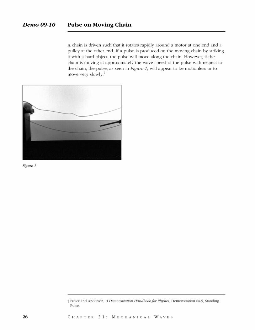
A chain is driven such that it rotates rapidly around a motor at one end and apulley at the other end. If a pulse is produced on the moving chain by strikingit with a hard object, the pulse will move along the chain. However, if thechain is moving at approximately the wave speed of the pulse with respect tothe chain, the pulse, as seen in Figure 1, will appear to be motionless or tomove very slowly.†
Demo 09-10 Pulse on Moving Chain
26 C H A P T E R 2 1 : M E C H A N I C A L W A V E S
Figure 1
† Freier and Anderson, A Demonstration Handbook for Physics, Demonstration Sa-5, StandingPulse.
When we send a wave pulse along this stationary chain, it travels rapidlydown the chain.
We’ll start the chain moving in this direction by spinning the support pulleys.When we send a pulse along the moving chain, the pulse appears to movevery slowly.
Pulse on Moving Chain / Script Demo 09-10
C H A P T E R 2 1 : M E C H A N I C A L W A V E S 27
Equipment
1. Motor-driven pulley of sizable diameter with a flat bottom trough.2. Secondary support pulley with similar characteristics.3. Long length of flat chain joined back onto itself forming a loop with no twists.4. Striker bar.5. Four clamps.6. Support system.
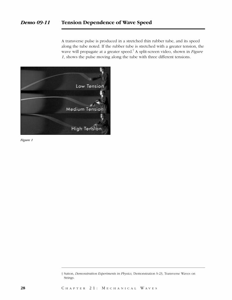
A transverse pulse is produced in a stretched thin rubber tube, and its speedalong the tube noted. If the rubber tube is stretched with a greater tension, thewave will propagate at a greater speed.† A split-screen video, shown in Figure1, shows the pulse moving along the tube with three different tensions.
Demo 09-11 Tension Dependence of Wave Speed
28 C H A P T E R 2 1 : M E C H A N I C A L W A V E S
Figure 1
† Sutton, Demonstration Experiments in Physics, Demonstration S-23, Transverse Waves onStrings.
We can send a wave pulse down this rubber tube by jerking sharply on thefree end.
Notice the propagation speed of the wave.
If we increase the tension on the rubber tubing by stretching it, how will thewave speed be affected?
The wave speed increases.
Further increasing the tension will even further increase the speed of the wave.
Tension Dependence of Wave Speed / Script Demo 09-11
C H A P T E R 2 1 : M E C H A N I C A L W A V E S 29
Equipment
1. Long length of rubber tubing.2. Fixed point on distant wall to attach rope.

A Shive Wave Machine† consists of a horizontal stiff iron wire along which rodshave been attached at right angles in the horizontal plane, as shown in Figure1. The video shows wave pulses propagating along the wave machine.
Demo 09-12 Torsional Waves
30 C H A P T E R 2 1 : M E C H A N I C A L W A V E S
Figure 1
† John N. Shive, Similarities in Wave Behavior (Bell Telephone Laboratories, third printing,January 1964).

This wave machine is used to demonstrate torsion waves. Long rods areattached to a square metal spine at regular intervals.
If we twist the spine by tipping the first rod, a torsion wave travels down thespine.
Torsional Waves / Script Demo 09-12
C H A P T E R 2 1 : M E C H A N I C A L W A V E S 31
Equipment
1. Bell Lab wave machine.2. Ends of rods should be coated with fluorescent paint.3. Black lights to highlight the rod tips.
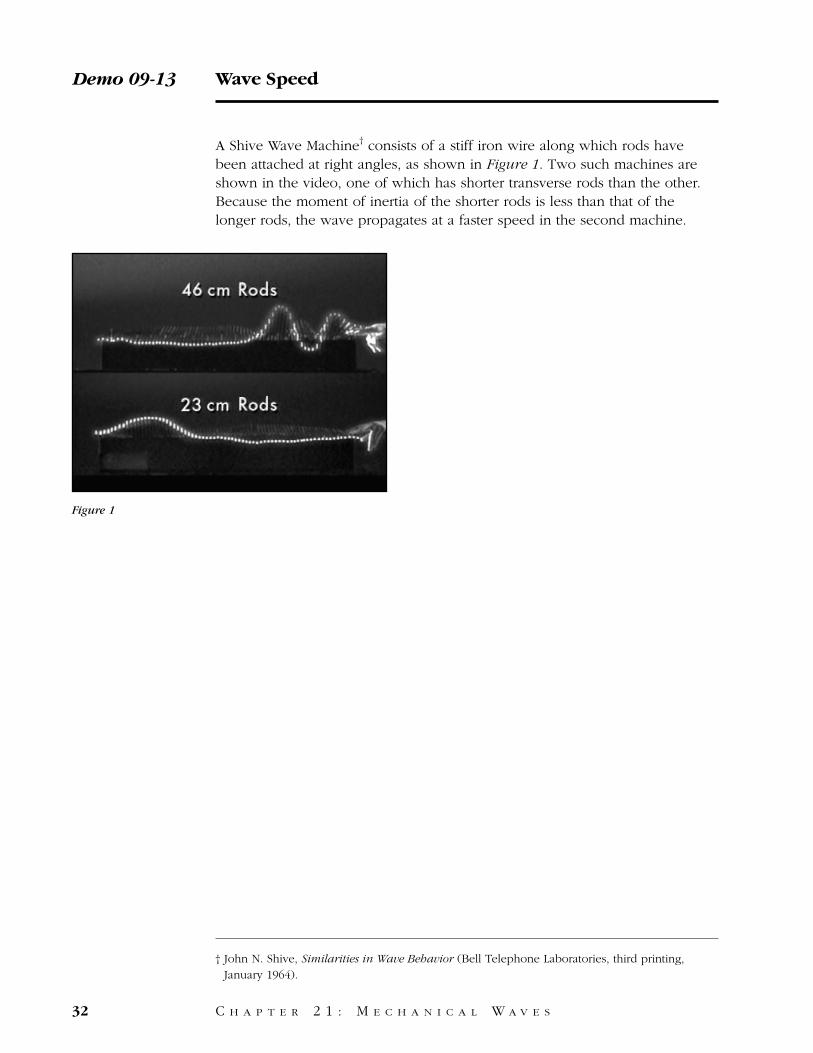
A Shive Wave Machine† consists of a stiff iron wire along which rods havebeen attached at right angles, as shown in Figure 1. Two such machines areshown in the video, one of which has shorter transverse rods than the other.Because the moment of inertia of the shorter rods is less than that of thelonger rods, the wave propagates at a faster speed in the second machine.
Demo 09-13 Wave Speed
32 C H A P T E R 2 1 : M E C H A N I C A L W A V E S
Figure 1
† John N. Shive, Similarities in Wave Behavior (Bell Telephone Laboratories, third printing,January 1964).
On this wave machine long rods are attached to a square wire spine at regularintervals. If we tip the first rod, a torsion wave travels down the spine.
This wave machine is identical to the first except that the rods are shorter.
A wave travels faster on this machine than on the other one.
Wave Speed / Script Demo 09-13
C H A P T E R 2 1 : M E C H A N I C A L W A V E S 33
Equipment
1. Same set up as previous demonstration.2. Add a second wave machine, prepared as above, with short rods.
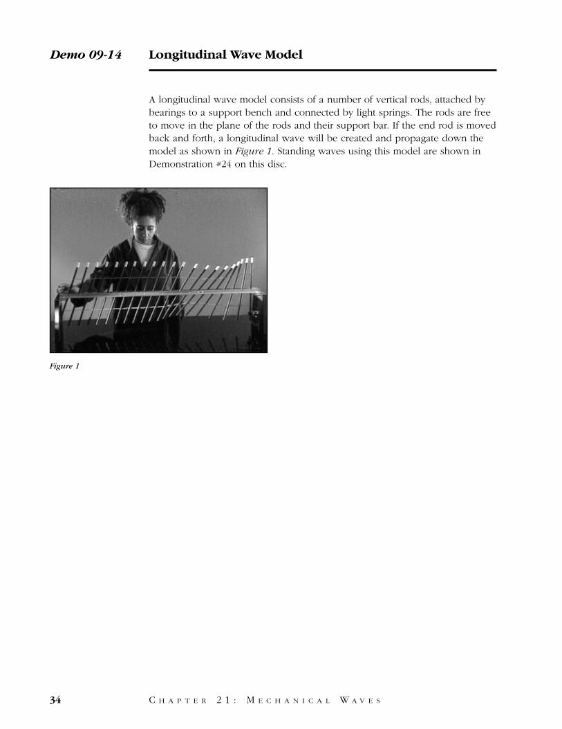
A longitudinal wave model consists of a number of vertical rods, attached bybearings to a support bench and connected by light springs. The rods are freeto move in the plane of the rods and their support bar. If the end rod is movedback and forth, a longitudinal wave will be created and propagate down themodel as shown in Figure 1. Standing waves using this model are shown inDemonstration #24 on this disc.
Demo 09-14 Longitudinal Wave Model
34 C H A P T E R 2 1 : M E C H A N I C A L W A V E S
Figure 1
This device is used to demonstrate longitudinal waves, where the displacementof the medium is parallel to the motion of the wave.
When the first rod is pushed sharply, springs between the rods pass themotion along.
Longitudinal Wave Model / Script Demo 09-14
C H A P T E R 2 1 : M E C H A N I C A L W A V E S 35
Equipment
Commercially available longitudinal wave machine with one end clamp.
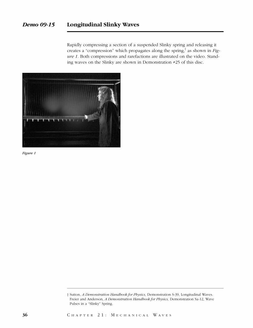
Rapidly compressing a section of a suspended Slinky spring and releasing itcreates a “compression” which propagates along the spring,† as shown in Fig-ure 1. Both compressions and rarefactions are illustrated on the video. Stand-ing waves on the Slinky are shown in Demonstration #25 of this disc.
Demo 09-15 Longitudinal Slinky Waves
36 C H A P T E R 2 1 : M E C H A N I C A L W A V E S
Figure 1
† Sutton, A Demonstration Handbook for Physics, Demonstration S-39, Longitudinal Waves. Freier and Anderson, A Demonstration Handbook for Physics, Demonstration Sa-12, WavePulses in a “Slinky” Spring.
We’ll use this hanging spring to demonstrate transmission of longtitudinalwaves.
If the end of the spring is compressed rapidly, a compression pulse travels thelength of the spring and reflects at the end.
If we pull rapidly on the end of the spring, an expansion pulse travels alongthe spring.
Longitudinal Slinky Waves / Script Demo 09-15
C H A P T E R 2 1 : M E C H A N I C A L W A V E S 37
Equipment
1. Bifilar suspended long metallic Slinky.2. Supporting framework.3. Paper flags every fifth coil to enhance visibility.
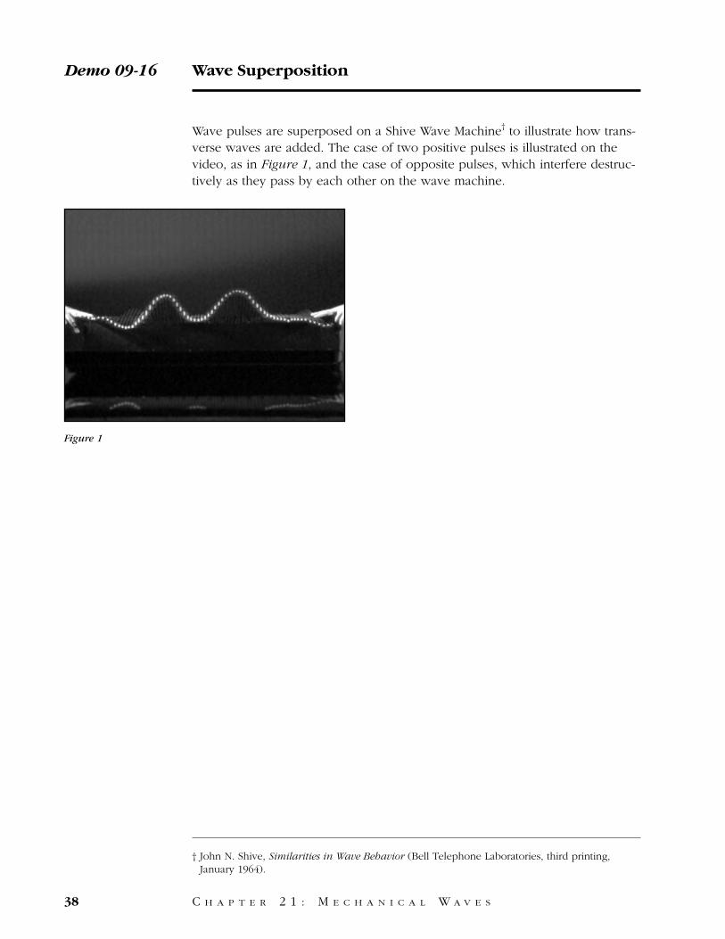
Wave pulses are superposed on a Shive Wave Machine† to illustrate how trans-verse waves are added. The case of two positive pulses is illustrated on thevideo, as in Figure 1, and the case of opposite pulses, which interfere destruc-tively as they pass by each other on the wave machine.
Demo 09-16 Wave Superposition
38 C H A P T E R 2 1 : M E C H A N I C A L W A V E S
Figure 1
† John N. Shive, Similarities in Wave Behavior (Bell Telephone Laboratories, third printing,January 1964).
Here is a torsion wave of medium amplitude travelling left to right.
Here is a wave of the same amplitude travelling right to left.
We’ll now send these waves in simultaneously to show what happens whenthey meet. The amplitudes add as the waves pass through each other. Thenthe waves continue on their way unchanged.
What will happen if the waves have equal but opposite amplitudes?
The waves cancel momentarily, then pass on.
Wave Superposition / Script Demo 09-16
C H A P T E R 2 1 : M E C H A N I C A L W A V E S 39
Equipment
Bell Lab wave machine, as previously described.
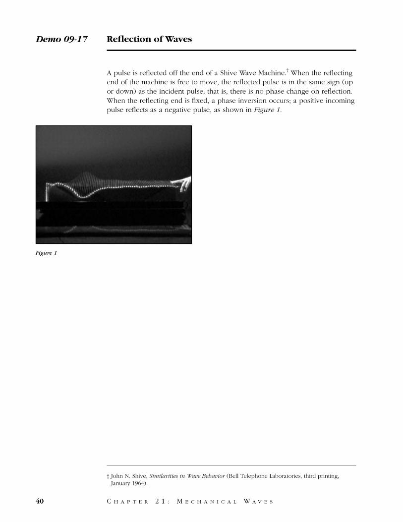
A pulse is reflected off the end of a Shive Wave Machine.† When the reflectingend of the machine is free to move, the reflected pulse is in the same sign (upor down) as the incident pulse, that is, there is no phase change on reflection.When the reflecting end is fixed, a phase inversion occurs; a positive incomingpulse reflects as a negative pulse, as shown in Figure 1.
Demo 09-17 Reflection of Waves
40 C H A P T E R 2 1 : M E C H A N I C A L W A V E S
Figure 1
† John N. Shive, Similarities in Wave Behavior (Bell Telephone Laboratories, third printing,January 1964).
We’ll send a torsional wave down this wave machine to show what happenswhen the wave reaches the end.
When the rod at the end is free to move, the wave reflects back with the samepositive amplitude as the incoming wave.
If we fasten the last rod on the machine so it can’t move, the reflected wavehas an amplitude opposite that of the incoming wave.
Reflection of Waves / Script Demo 09-17
C H A P T E R 2 1 : M E C H A N I C A L W A V E S 41
Equipment
1. Same as Demonstration 09-16.2. End clamp.
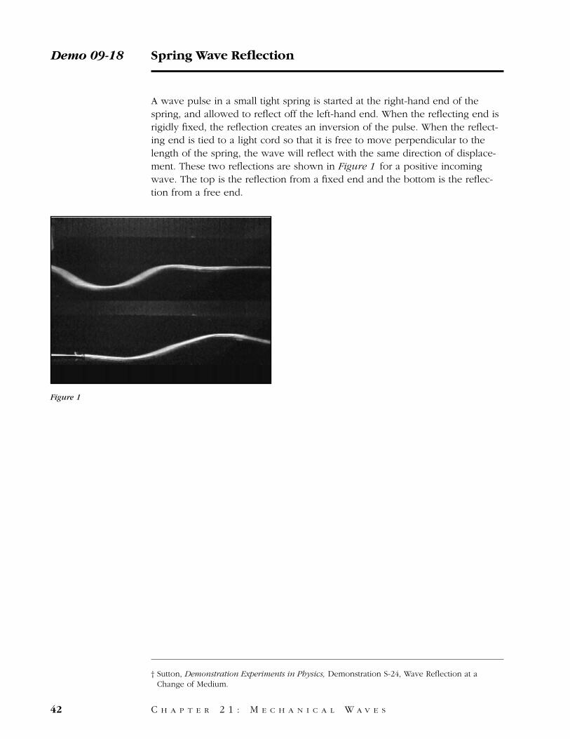
A wave pulse in a small tight spring is started at the right-hand end of thespring, and allowed to reflect off the left-hand end. When the reflecting end isrigidly fixed, the reflection creates an inversion of the pulse. When the reflect-ing end is tied to a light cord so that it is free to move perpendicular to thelength of the spring, the wave will reflect with the same direction of displace-ment. These two reflections are shown in Figure 1 for a positive incomingwave. The top is the reflection from a fixed end and the bottom is the reflec-tion from a free end.
Demo 09-18 Spring Wave Reflection
42 C H A P T E R 2 1 : M E C H A N I C A L W A V E S
Figure 1
† Sutton, Demonstration Experiments in Physics, Demonstration S-24, Wave Reflection at aChange of Medium.
When a wave pulse on a spring reaches the end of the spring, some or all ofthe wave is reflected.
In this first case, the end of the spring is attached to a rod so that it can’tmove. Here’s how a wave reflects from the end.
We’ll repeat that in slow motion.
Notice that the reflected wave is an inverted version of the incoming wave.Now we’ll tie the end of the spring to a long, light string so that the endmoves freely.
The wave now reflects without inverting.
Let’s compare the two types of reflection side-by-side.
Spring Wave Reflection / Script Demo 09-18
C H A P T E R 2 1 : M E C H A N I C A L W A V E S 43
Equipment
1. Long brass spring that has a low mass string with a loop tied to the far end of the spring.2. Clamp and bar:
a: slide far end of spring over the bar to show a fixed end, andb: slide the connected string over the bar, after removing the spring itself, which willapproximate a spring with a free end.
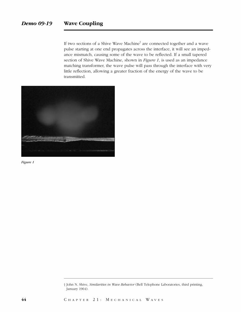
If two sections of a Shive Wave Machine† are connected together and a wavepulse starting at one end propagates across the interface, it will see an imped-ance mismatch, causing some of the wave to be reflected. If a small taperedsection of Shive Wave Machine, shown in Figure 1, is used as an impedancematching transformer, the wave pulse will pass through the interface with verylittle reflection, allowing a greater fraction of the energy of the wave to betransmitted.
Demo 09-19 Wave Coupling
44 C H A P T E R 2 1 : M E C H A N I C A L W A V E S
Figure 1
† John N. Shive, Similarities in Wave Behavior (Bell Telephone Laboratories, third printing,January 1964).

On this wave machine, long rods are attached to a square metal spine at regu-lar intervals. If we tip the first rod sharply, a torsion wave travels down themachine at a constant speed.
This wave machine is identical except that the rods are shorter. Waves movingon this machine travel more quickly than waves on the first machine.
If we hook the two machines together and send a wave along, part of thewave is reflected at the coupling point, and part is transmitted.
This machine has rods that decrease in length from those of the first machineto those of the second.
A wave now passes smoothly through the interface with little reflection.
Wave Coupling / Script Demo 09-19
C H A P T E R 2 1 : M E C H A N I C A L W A V E S 45
Equipment
1. Long section of Bell Lab wave machine.2. Short section of Bell Lab wave machine.3. Interface section of Bell Lab wave machine (all prepared as previously described).4. Four or five black lights.
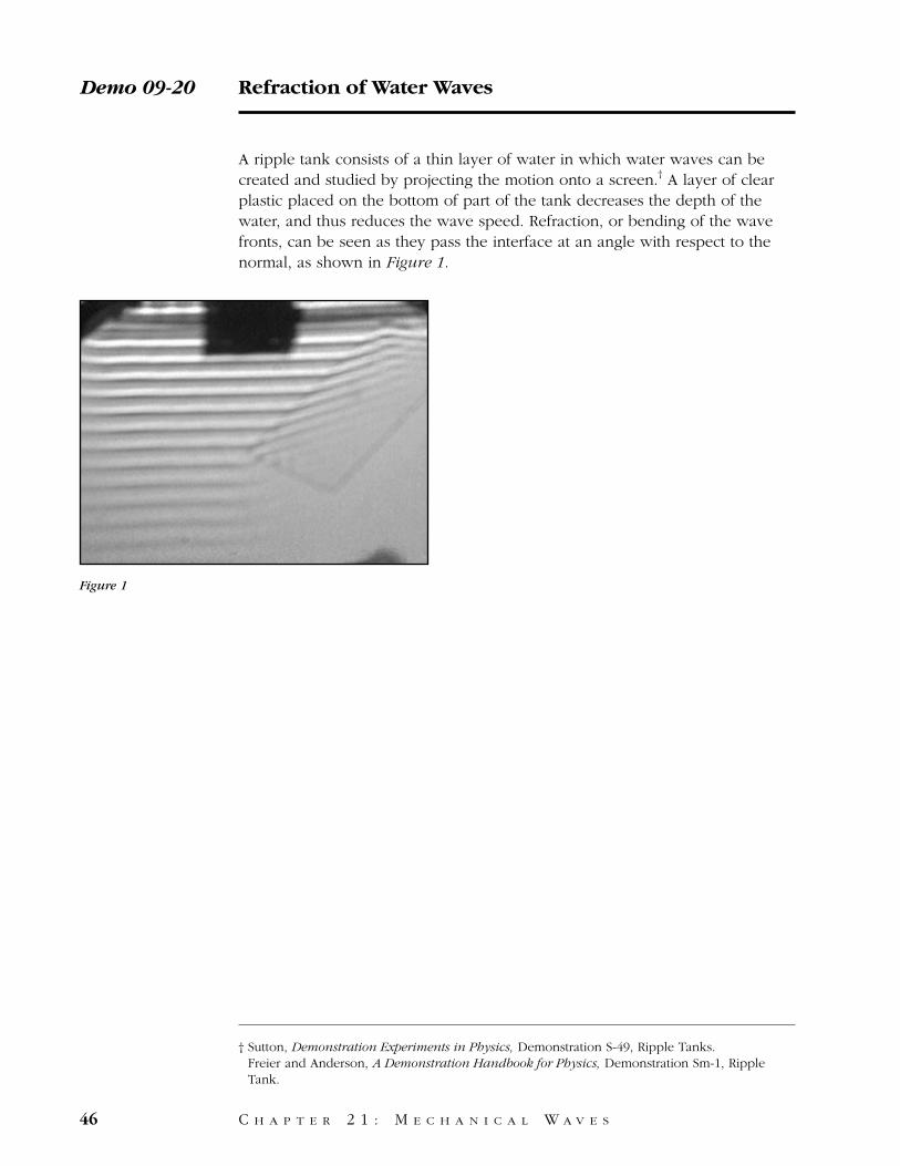
A ripple tank consists of a thin layer of water in which water waves can becreated and studied by projecting the motion onto a screen.† A layer of clearplastic placed on the bottom of part of the tank decreases the depth of thewater, and thus reduces the wave speed. Refraction, or bending of the wavefronts, can be seen as they pass the interface at an angle with respect to thenormal, as shown in Figure 1.
Demo 09-20 Refraction of Water Waves
46 C H A P T E R 2 1 : M E C H A N I C A L W A V E S
Figure 1
† Sutton, Demonstration Experiments in Physics, Demonstration S-49, Ripple Tanks. Freier and Anderson, A Demonstration Handbook for Physics, Demonstration Sm-1, RippleTank.
We’ll use this ripple tank, which projects an image of waves on the surface ofwater, to demonstrate the refraction of water waves.
When we put a rectangular pane of glass into the tank, the water over theglass is shallower than the rest in the tank. When the waves cross over into theshallower water, they are refracted to the side.
Refraction of Water Waves / Script Demo 09-20
C H A P T E R 2 1 : M E C H A N I C A L W A V E S 47
Equipment
1. Ripple tank.2. Rectangular plane of glass.3. Light source.4. Vibrator system.5. Projection screen.
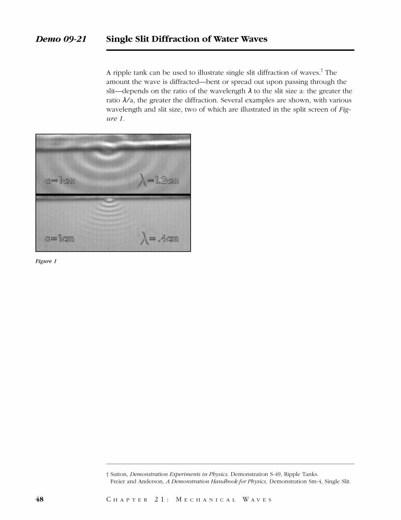
A ripple tank can be used to illustrate single slit diffraction of waves.† Theamount the wave is diffracted—bent or spread out upon passing through theslit—depends on the ratio of the wavelength λ to the slit size a: the greater theratio λ ⁄a, the greater the diffraction. Several examples are shown, with variouswavelength and slit size, two of which are illustrated in the split screen of Fig-ure 1.
Demo 09-21 Single Slit Diffraction of Water Waves
48 C H A P T E R 2 1 : M E C H A N I C A L W A V E S
Figure 1
† Sutton, Demonstration Experiments in Physics, Demonstration S-49, Ripple Tanks. Freier and Anderson, A Demonstration Handbook for Physics, Demonstration Sm-4, Single Slit.
We’ll use this ripple tank, which projects an image of waves on the surface ofwater, to show diffraction through a single slit.
If we put a single slit in front of the waves, the waves emerging from the slitare no longer plane waves. The waves are now diffracted strongly to the sides.
If we decrease the wave length the amount of refraction is reduced.
This split screen view shows the diffraction at two different wave lengths.
Increasing the width of the slit also decreases the diffraction of the wave.
This split screen view shows the diffraction with two different slit widths.
Single Slit Diffraction of Water Waves / Script Demo 09-21
C H A P T E R 2 1 : M E C H A N I C A L W A V E S 49
Equipment
1. Complete ripple tank assembly.2. Single slit apparatus.
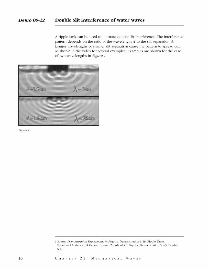
A ripple tank can be used to illustrate double slit interference. The interferencepattern depends on the ratio of the wavelength λ to the slit separation d.Longer wavelengths or smaller slit separation cause the pattern to spread out,as shown in the video for several examples. Examples are shown for the caseof two wavelengths in Figure 1.
Demo 09-22 Double Slit Interference of Water Waves
50 C H A P T E R 2 1 : M E C H A N I C A L W A V E S
Figure 1
† Sutton, Demonstration Experiments in Physics, Demonstration S-49, Ripple Tanks. Freier and Anderson, A Demonstration Handbook for Physics, Demonstration Sm-5, DoubleSlit.
We’ll use this ripple tank, which projects an image of waves on the surface ofwater, to show interference of waves from two closely spaced slits. When weput a pair of slits in front of the waves, an interference pattern results.
Decreasing the wave length increases the number of nodal lines in the pattern.
This split screen view shows the patterns resulting from the two wave lengths.
Increasing the separation of the slits also increases the number of nodal lines.
This split screen view shows the patterns resulting from the two slit spacings.
Double Slit Interference of Water Waves / Script Demo 09-22
C H A P T E R 2 1 : M E C H A N I C A L W A V E S 51
Equipment
1. Complete ripple tank assembly.2. Double slit apparatus.
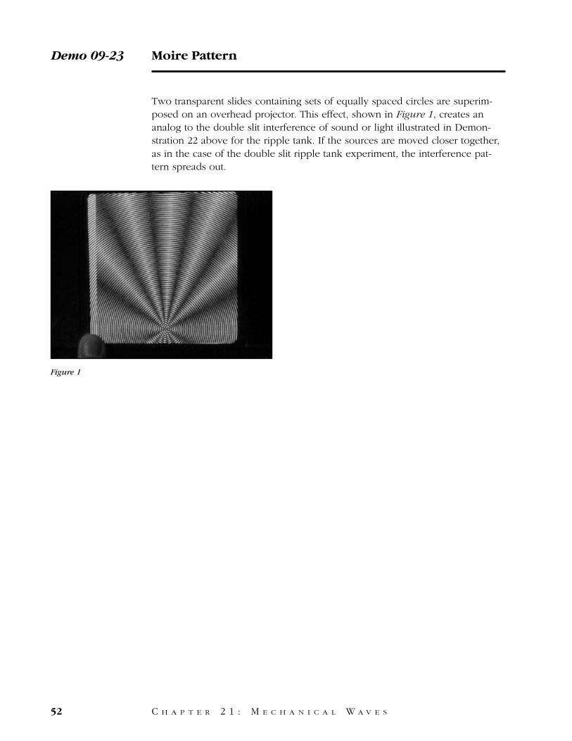
Two transparent slides containing sets of equally spaced circles are superim-posed on an overhead projector. This effect, shown in Figure 1, creates ananalog to the double slit interference of sound or light illustrated in Demon-stration 22 above for the ripple tank. If the sources are moved closer together,as in the case of the double slit ripple tank experiment, the interference pat-tern spreads out.
Demo 09-23 Moire Pattern
52 C H A P T E R 2 1 : M E C H A N I C A L W A V E S
Figure 1
Here are a pair of slides with identical concentric circles printed on them.
We’ll use them to simulate the interference of waves from two coherentsources.
If we place the slides one on top of the other, a regular pattern appears.
Moving the centers closer together widens the pattern of light and dark area.
Moire Pattern / Script Demo 09-23
C H A P T E R 2 1 : M E C H A N I C A L W A V E S 53
Equipment
1. Overhead projector.2. Mask for size of slides.3. Two slides with identical concentric circles.

54

C H A P T E R 2 2
S T A N D I N G W A V E S
55
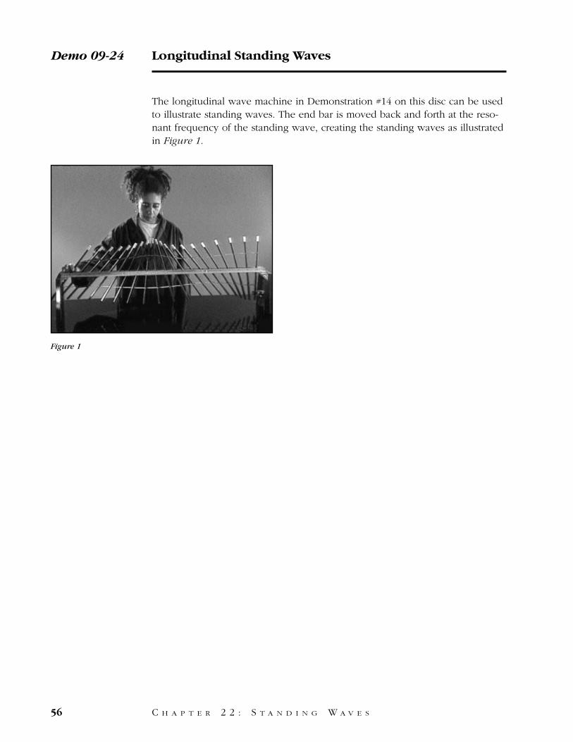
The longitudinal wave machine in Demonstration #14 on this disc can be usedto illustrate standing waves. The end bar is moved back and forth at the reso-nant frequency of the standing wave, creating the standing waves as illustratedin Figure 1.
Demo 09-24 Longitudinal Standing Waves
56 C H A P T E R 2 2 : S T A N D I N G W A V E S
Figure 1
This device is used to demonstrate longitudinal waves, where the displacementof the medium is parallel to the motion of the wave.
When the first rod is pushed sharply, springs between the rods pass themotion along.
If the first rod is moved back and forth at certain frequencies, standing wavesappear.
Longitudinal Standing Waves / Script Demo 09-24
C H A P T E R 2 2 : S T A N D I N G W A V E S 57
Equipment
Same as Demonstration 09-14, with one end clamp.
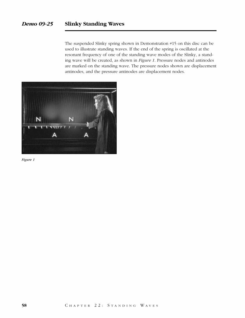
The suspended Slinky spring shown in Demonstration #15 on this disc can beused to illustrate standing waves. If the end of the spring is oscillated at theresonant frequency of one of the standing wave modes of the Slinky, a stand-ing wave will be created, as shown in Figure 1. Pressure nodes and antinodesare marked on the standing wave. The pressure nodes shown are displacementantinodes, and the pressure antinodes are displacement nodes.
Demo 09-25 Slinky Standing Waves
58 C H A P T E R 2 2 : S T A N D I N G W A V E S
Figure 1
If we push and pull the end of this hanging spring repeatedly, waves of bothcompression and expansion travel along the spring.
If we push and pull at a certain frequency, a longitudinal standing waveappears on the spring.
Pushing and pulling at a higher frequency creates a standing wave with ashorter wavelength.
The nodes and antinodes of the standing waves have been marked in theseslow-motion views.
Slinky Standing Waves / Script Demo 09-25
C H A P T E R 2 2 : S T A N D I N G W A V E S 59
Equipment
Same as Demonstration 09-15.
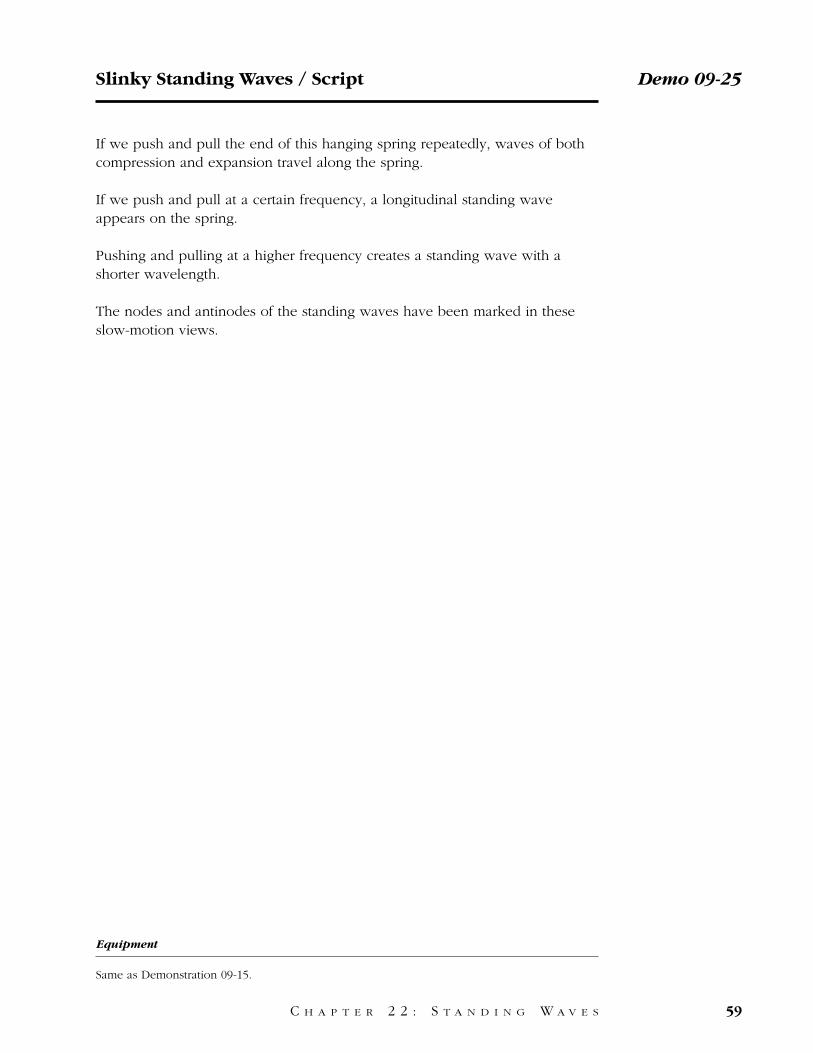
The Shive Wave Machine can be used to illustrate standing waves.† If one endof the machine is moved up and down at the resonant frequency of a standingwave mode, that standing wave will be created, as shown in Figure 1.
Demo 09-26 Standing Waves
60 C H A P T E R 2 2 : S T A N D I N G W A V E S
Figure 1
† John N. Shive, Similarities in Wave Behavior (Bell Telephone Laboratories, third printing,January 1964).
If we send a wave pulse along this wave machine, it is reflected at the end. Ifwe continue sending pulses at regular intervals, and then adjust the frequencyuntil it is just right, the incoming and reflected waves add to form a standingwave.
Increasing the frequency slightly destroys the standing wave. Increasing thefrequency even further to just the right value creates another standing wavewith a shorter wavelength.
Standing Waves / Script Demo 09-26
C H A P T E R 2 2 : S T A N D I N G W A V E S 61
Equipment
1. Short section of Bell Lab wave machine prepared as discussed earlier.2. Two black lights.
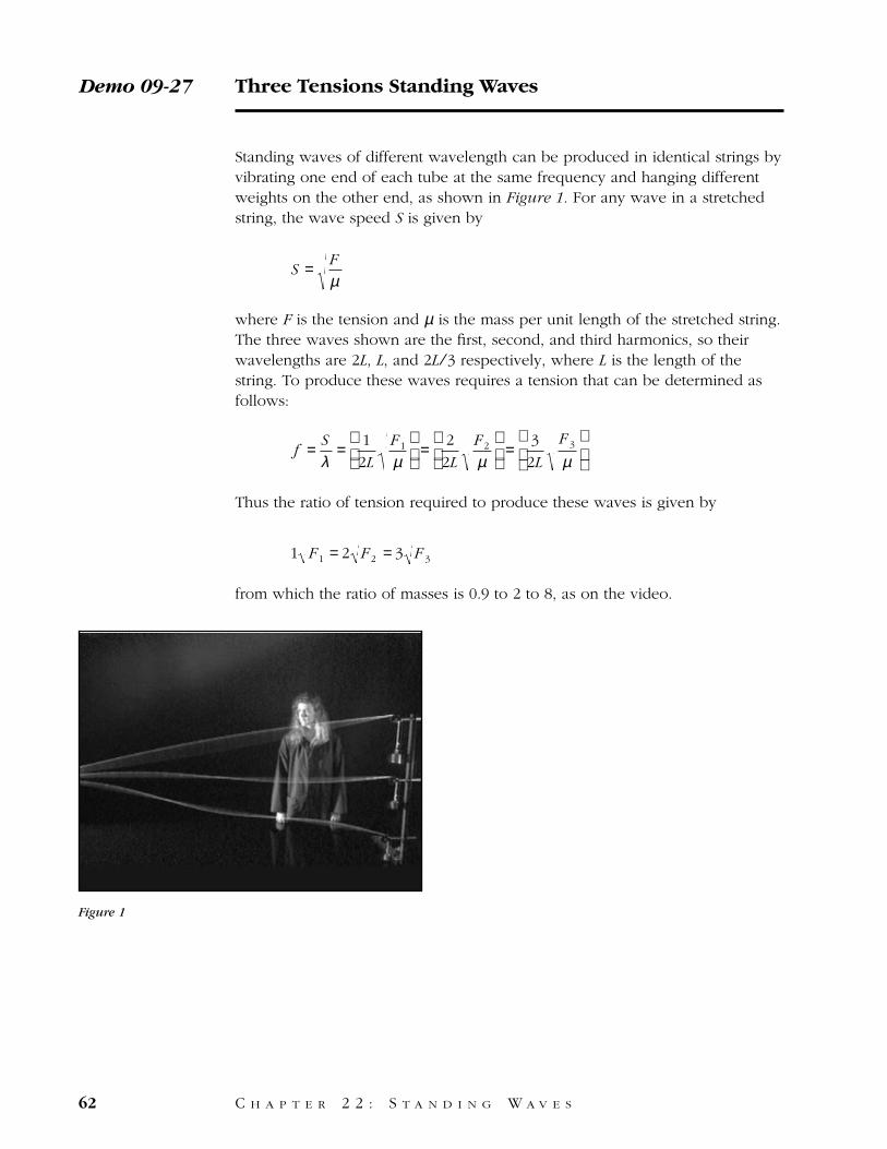
Standing waves of different wavelength can be produced in identical strings byvibrating one end of each tube at the same frequency and hanging differentweights on the other end, as shown in Figure 1. For any wave in a stretchedstring, the wave speed S is given by
where F is the tension and µ is the mass per unit length of the stretched string.The three waves shown are the first, second, and third harmonics, so theirwavelengths are 2L, L, and 2L ⁄ 3 respectively, where L is the length of thestring. To produce these waves requires a tension that can be determined asfollows:
Thus the ratio of tension required to produce these waves is given by
from which the ratio of masses is 0.9 to 2 to 8, as on the video.
1 F 1 = 2 F 2 = 3 F 3
f = S
λ= 1
2L
F 1
µ
= 2
2L
F 2
µ
= 3
2L
F 3
µ
S = F
µ
Demo 09-27 Three Tensions Standing Waves
62 C H A P T E R 2 2 : S T A N D I N G W A V E S
Figure 1
Three strings under different tensions will be used to demonstrate the effect oftension on standing wave formation.
The ends of the strings hang over pulleys, with weights of 0.9 newtons, 2 new-tons, and 8 newtons providing the tensions.
All three strings will be driven at the same frequency.
Here are the three standing wave patterns produced.
If we decrease the tension in the center string by lifting up on its weight, itsstanding wave pattern changes to match that of the lower string.
If we increase the tension in the center string by pulling down on the weight,its standing wave pattern changes to match that of the upper string.
Three Tensions Standing Waves / Script Demo 09-27
C H A P T E R 2 2 : S T A N D I N G W A V E S 63
Equipment
1. Motor-driven can vibrator.2. Three lengths of strings with one end tied to the vibrator and the other ends passing over
three separate distant pulleys.3. Support system for three pulleys.4. Appropriate weights for each of the three strings.5. Several clamps.
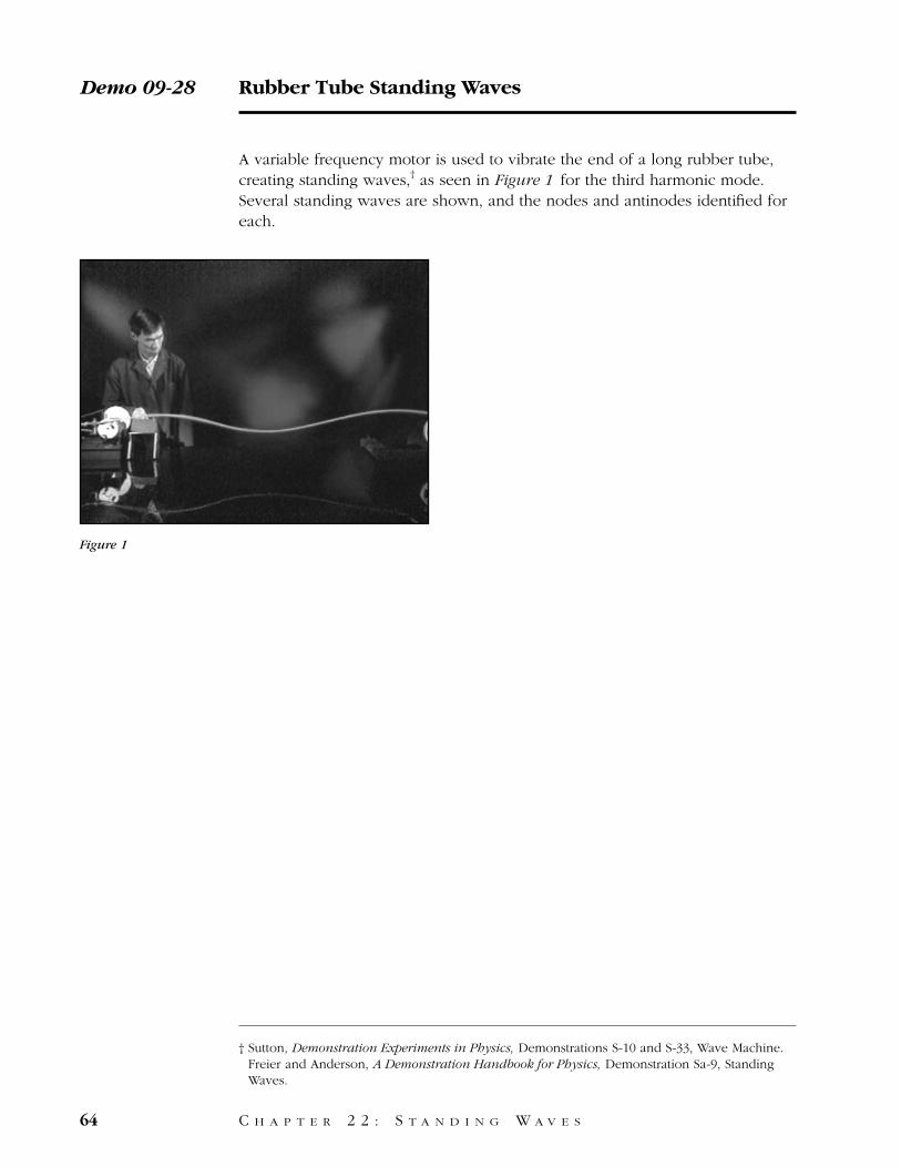
A variable frequency motor is used to vibrate the end of a long rubber tube,creating standing waves,† as seen in Figure 1 for the third harmonic mode.Several standing waves are shown, and the nodes and antinodes identified foreach.
Demo 09-28 Rubber Tube Standing Waves
64 C H A P T E R 2 2 : S T A N D I N G W A V E S
Figure 1
† Sutton, Demonstration Experiments in Physics, Demonstrations S-10 and S-33, Wave Machine. Freier and Anderson, A Demonstration Handbook for Physics, Demonstration Sa-9, StandingWaves.
We’ll now show standing wave formation resulting from different driving fre-quencies.
This rubber tube is put under tension by a weight hanging from the end.
A beater strikes the end of the tubing at an adjustable frequency.
At a very low frequency, the tubing hardly reacts. But as the frequency israised, the fundamental of the tubing is excited and the amplitude increasesgreatly.
If we increase the frequency, the fundamental disappears. As we continue toincrease the frequency, we excite the second harmonic.
We continue to raise the driving frequency, and strike the third harmonic.
Here are some of the higher harmonics in slow motion.
Rubber Tube Standing Waves / Script Demo 09-28
C H A P T E R 2 2 : S T A N D I N G W A V E S 65
Equipment
1. Variable speed motor control.2. Vibrating assembly.3. Length of rubber tubing.4. Free-wheeling pulley5. Hooked weight.6. Clamps to hold everything securely.
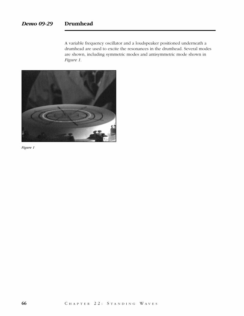
A variable frequency oscillator and a loudspeaker positioned underneath adrumhead are used to excite the resonances in the drumhead. Several modesare shown, including symmetric modes and antisymmetric mode shown inFigure 1.
Demo 09-29 Drumhead
66 C H A P T E R 2 2 : S T A N D I N G W A V E S
Figure 1
Have you ever wondered how the head of a drum vibrates when it is struck?We’ll use this flexible rubber diaphragm and this speaker to show some of theforms of vibration.
The speaker drives the rubber drumhead with sound waves from beneath.
Here is the fundamental vibration of the drumhead, seen with a strobe light toslow down the motion.
Here is an oscillation at a higher frequency. Notice the circular nodal line.
Here is a different type of oscillation, with a nodal line running across thediameter.
Drumhead / Script Demo 09-29
C H A P T E R 2 2 : S T A N D I N G W A V E S 67
Equipment
1. Rubber diaphragm.2. Speaker.3. Audio oscillator.4. Strobe light.
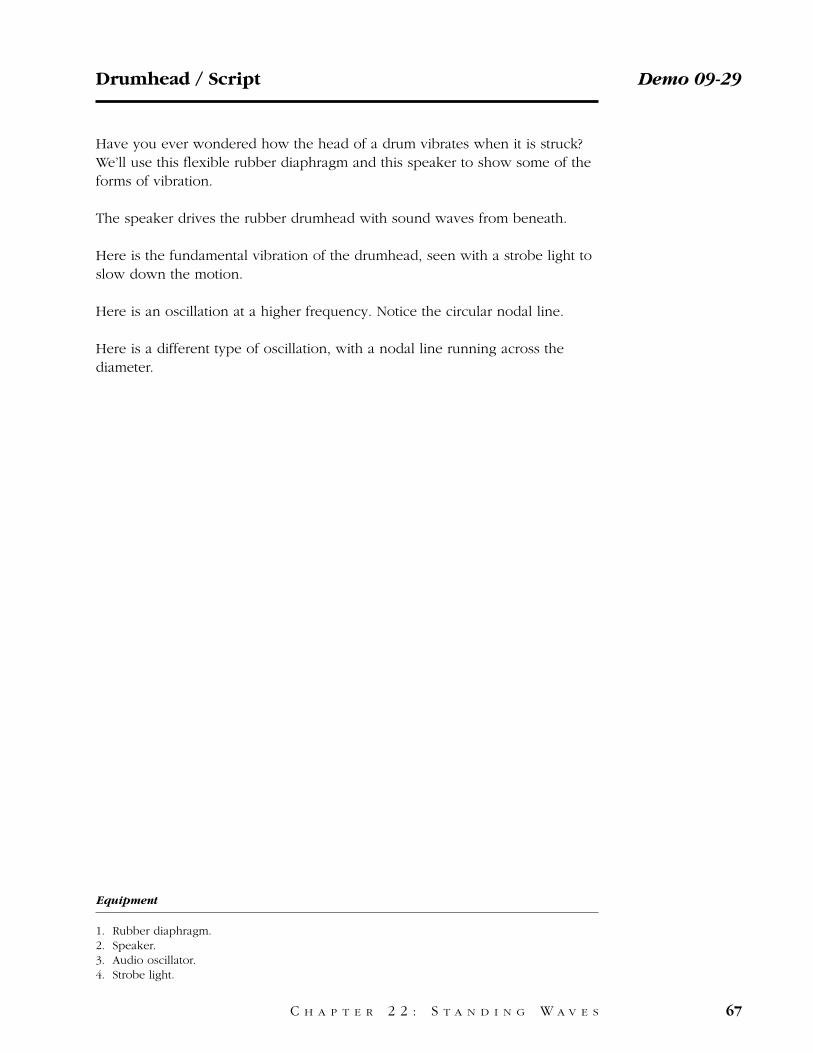
A square black anodized aluminum plate is excited in its center by vibrationsin the 20 kilohertz range originating from magnetostriction in a thin-walledannealed nickel tube. When the oscillator creating the oscillating magneticfield is tuned to a resonant frequency of the aluminum plate, standing wavesare formed.† These standing waves can be viewed by sprinkling sand onto theplate, because the sand will quickly drift to the nodal lines, as shown in Figure1. Several examples are shown amd the frequency of each displayed on thescreen with the standing wave pattern. This type of oscillation also occurs inthe back and the belly of a violin, enhancing the intensity of higher harmonicsin the violin tone.
Demo 09-30 Chladni Plates
68 C H A P T E R 2 2 : S T A N D I N G W A V E S
Figure 1
† E. R. Pinkston, Lecture demonstration of nodal patterns, Am. J. Phys. 14, 138 (1946).
In this demonstration we will observe standing wave vibrations of an alu-minum plate.
An oscillator in the 10 to 30 kilohertz range produces sine waves which areamplified by this audio amplifier and fed into this small coil.
A piece of thin-walled annealed nickel tube is mounted rigidly to this blackanodized aluminum plate, and the tube is inserted into the coil. The process ofmagnetostriction in the nickel tube converts magnetic oscillations of the coilinto mechanical vibrations.
The frequency is set, as shown by the inset at the lower left of the picture, andsand poured onto the plate. The sand illustrates the standing wave pattern bygathering along the nodal lines.
Now the frequency is adjusted to show various standing waves in the plate.
The wooden plates on a violin would exhibit this type of oscillation.
Chladni Plates / Script Demo 09-30
C H A P T E R 2 2 : S T A N D I N G W A V E S 69
Equipment
1. Square, flat black plate attached at its center to a thin-walled annealed nickel tube.2. Support assembly for plate with small electric coil on its underside, located at the center
hole.3. Audio oscillator.4. Amplifier.5. Supply of sand.