Embed Size (px)
Citation preview
4/13/2018 Va3KGS 1
Steerable Array “The Vertical Beam for Low Bands”
Kevin G. Smith, CET, ME
Ridgeway, Ontario, FN02lv
VA3KGS
VA3AC
Presented to www.NPARC.on.ca (April 12, 2018)
4/13/2018 Va3KGS 2
Introduction
What is a Steerable Array?
What do you Gain by doing this?
What Band’s to use it on?
Design Philosophy, K2AV & Steerable
Construction
Testing
Results (Contests)
Reference Material used
4/13/2018 Va3KGS 3
What is a Steerable Array ?
STEERABLE is to control the direction of the
Receiving and Sending signals. (Vertical
Beam).
By using Relay’s switching in and out different
Phasing Lines harnesses (Coax).
ARRAY is to be 2 or more vertical Antenna’s
that are used for Receiving and Sending.
Wire or Poles
4/13/2018 Va3KGS 4
What do you Gain?
Typical Low Band DX Antennas used today
are made of ¼ wave single wire, and are
vertical in nature (Inverted L).
1 Vertical = ~0db Gain
2 Verticals = ~3db Gain
3 Verticals = ~6db Gain
4 Verticals = ~10db Gain
More Contacts
4/13/2018 Va3KGS 5
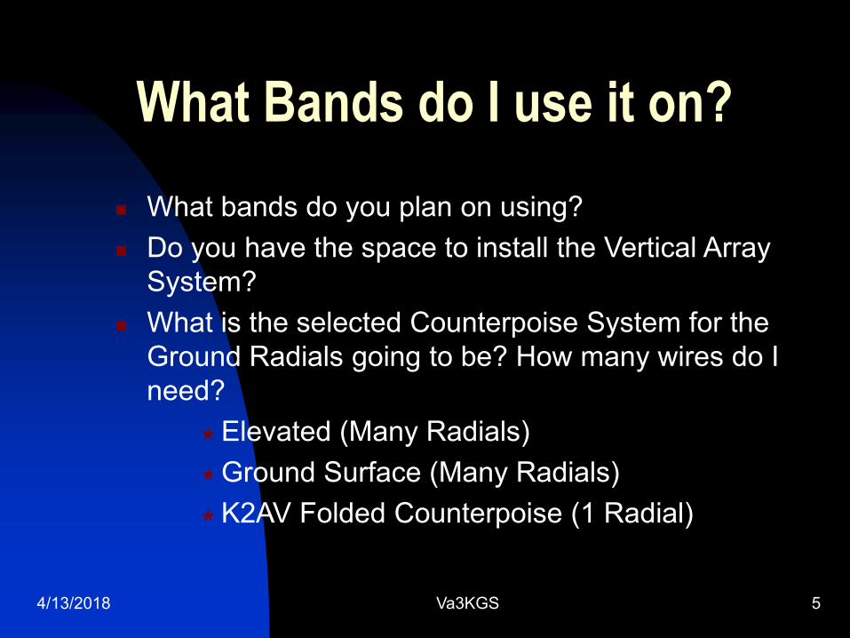
What Bands do I use it on?
What bands do you plan on using?
Do you have the space to install the Vertical Array
System?
What is the selected Counterpoise System for the
Ground Radials going to be? How many wires do I
need?
Elevated (Many Radials)
Ground Surface (Many Radials)
K2AV Folded Counterpoise (1 Radial)
4/13/2018 Va3KGS 6
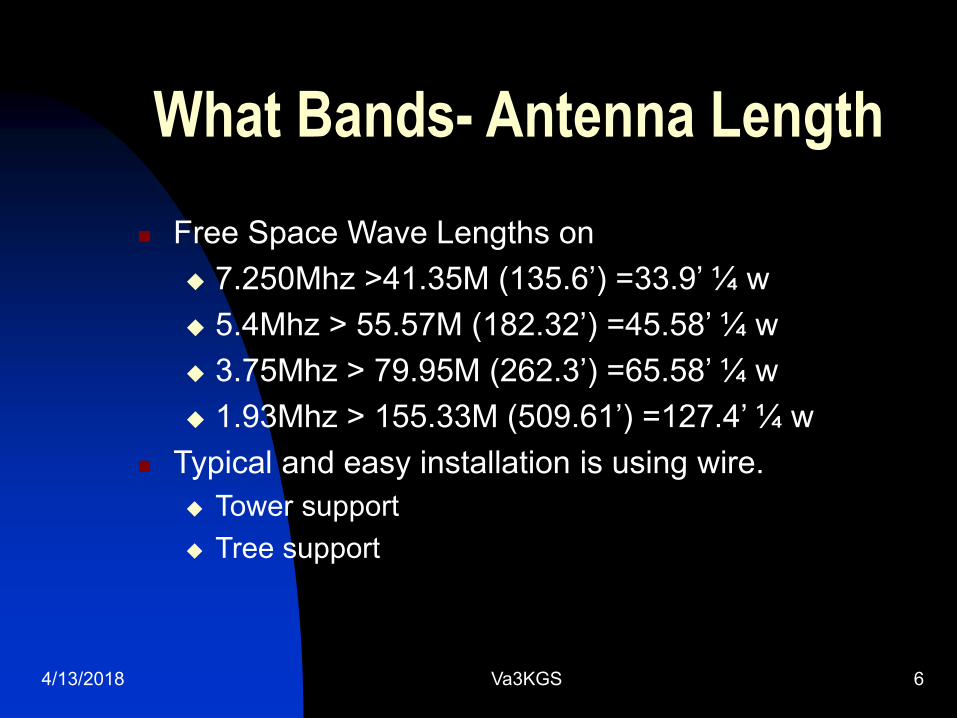
What Bands- Antenna Length
Free Space Wave Lengths on
7.250Mhz >41.35M (135.6’) =33.9’ ¼ w
5.4Mhz > 55.57M (182.32’) =45.58’ ¼ w
3.75Mhz > 79.95M (262.3’) =65.58’ ¼ w
1.93Mhz > 155.33M (509.61’) =127.4’ ¼ w
Typical and easy installation is using wire.
Tower support
Tree support
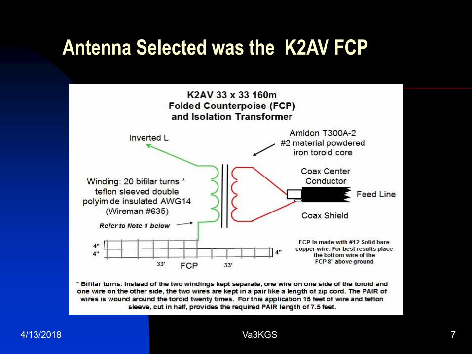
Antenna Selected was the K2AV FCP
4/13/2018 Va3KGS 7
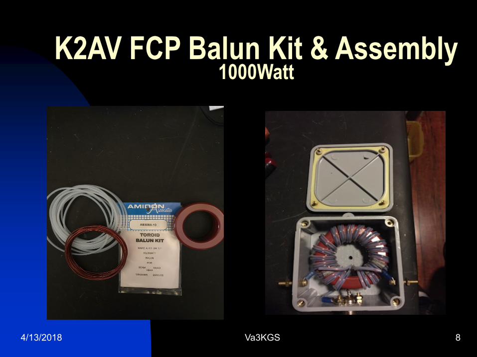
K2AV FCP Balun Kit & Assembly1000Watt
4/13/2018 Va3KGS 8
Steering the Antenna
“Steerable Arrays for the Low Bands” by B.
Alexander W5AH, The ARRL Antenna Compendium
Volume 2 1989
Makes reference to:
“Broadband Steerable Phased Arrays” by RC
Fenwick K5RR & RR Shell PhD, QST April 1977
4/13/2018 Va3KGS 9
4/13/2018 Va3KGS 10
4/13/2018 Va3KGS 11
4/13/2018 Va3KGS 12
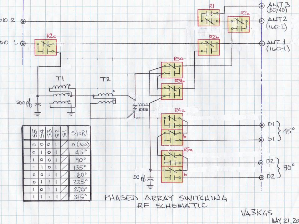
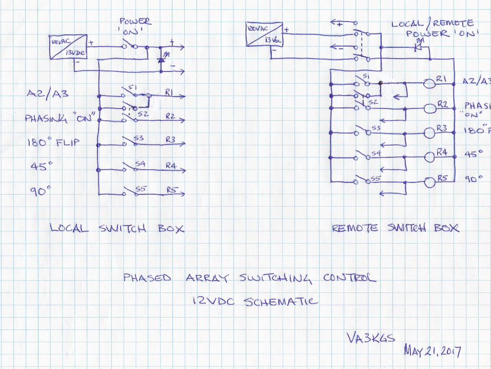
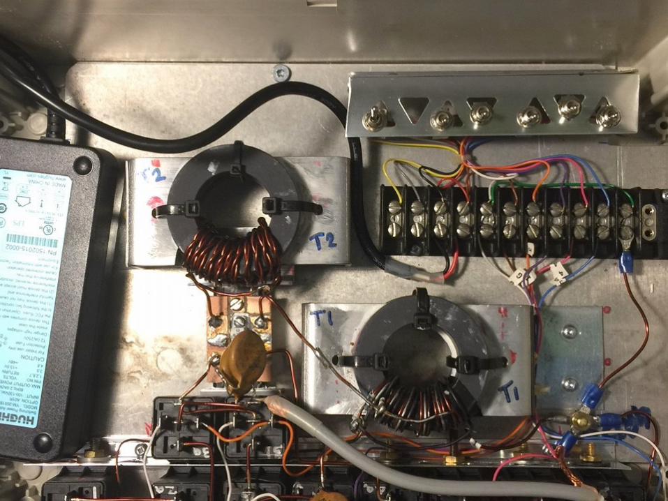
The Switching Control Scheme
Out of 360 degrees, I would like to switch the antennas every 45 degrees giving 8 positions to play with.
By using;
40A 12Vdc Control Relays
Impedance Matching 2:1 Transformer
Hybrid Power Divider
Control Switches
50 ohm LMR400 coax for all cables
4/13/2018 Va3KGS 13
4/13/2018 Va3KGS 14
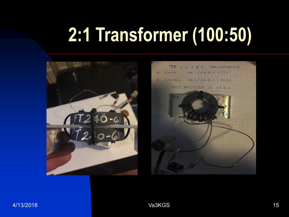
2:1 Transformer (100:50)
4/13/2018 Va3KGS 15
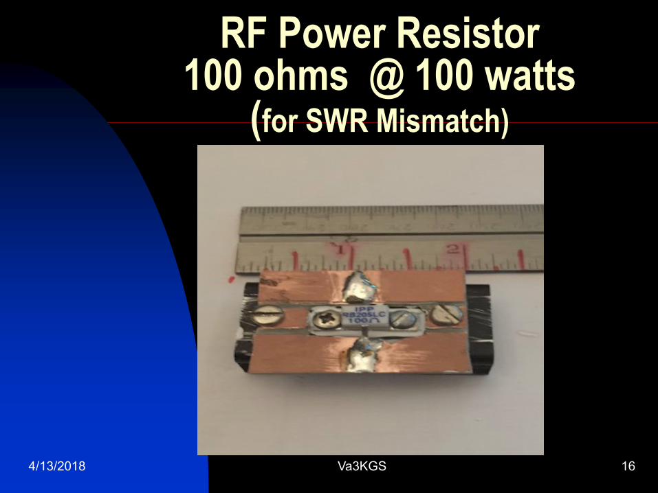
RF Power Resistor100 ohms @ 100 watts
(for SWR Mismatch)
4/13/2018 Va3KGS 16
4/13/2018 Va3KGS 17
4/13/2018 Va3KGS 18
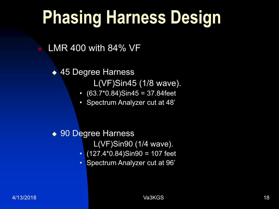
Phasing Harness Design
LMR 400 with 84% VF
45 Degree Harness
L(VF)Sin45 (1/8 wave).• (63.7*0.84)Sin45 = 37.84feet
• Spectrum Analyzer cut at 48’
90 Degree Harness
L(VF)Sin90 (1/4 wave).
• (127.4*0.84)Sin90 = 107 feet
• Spectrum Analyzer cut at 96’
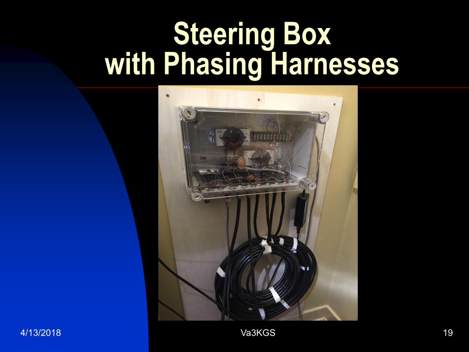
Steering Box with Phasing Harnesses
4/13/2018 Va3KGS 19
Testing
Equipment used:
SigLent Digital Scope SDS-1202X-E
SigLent Spectrum Analyzer SSA 3021X
RigExpert Antenna Analyzer AA-600
Telepost Digital Station Monitor LP-500
Telepost Digial Vector RF Wattmeter LP-100A
4/13/2018 Va3KGS 20
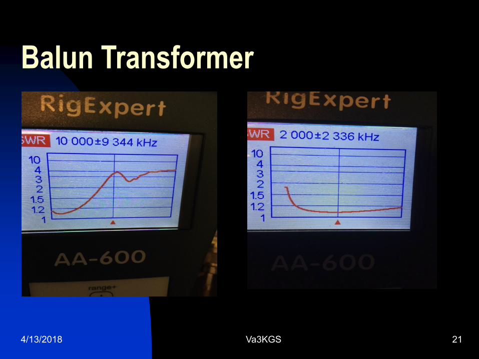
Balun Transformer
4/13/2018 Va3KGS 21
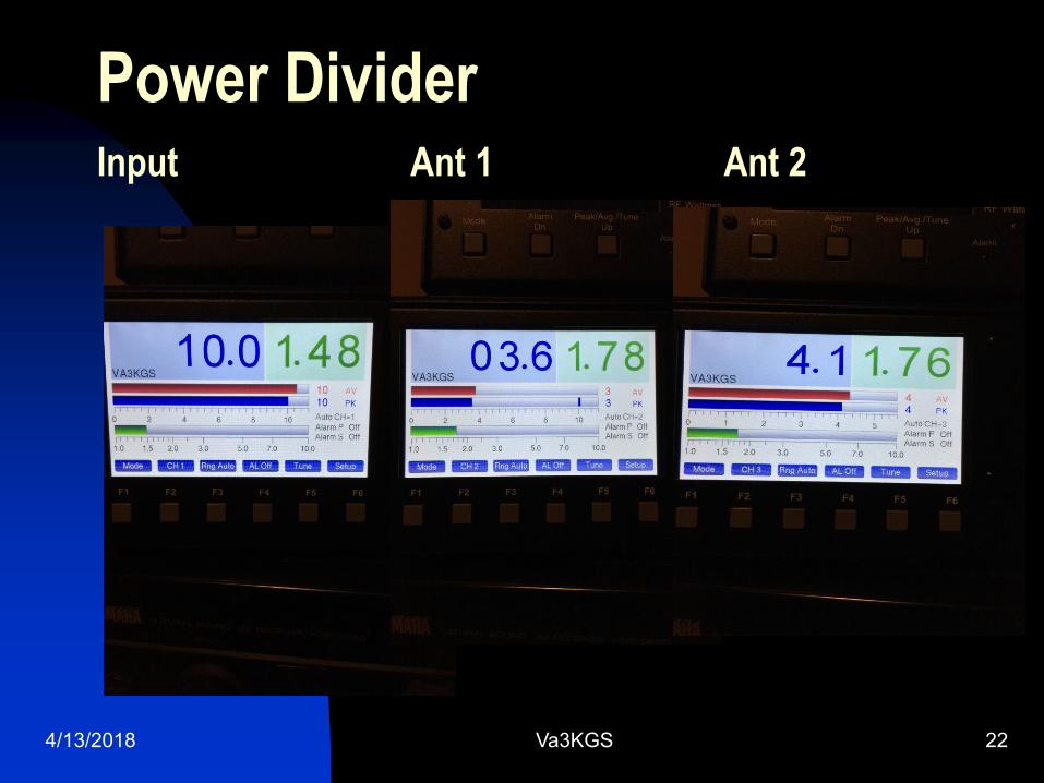
Power DividerInput Ant 1 Ant 2
4/13/2018 Va3KGS 22
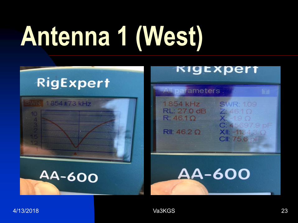
Antenna 1 (West)
4/13/2018 Va3KGS 23
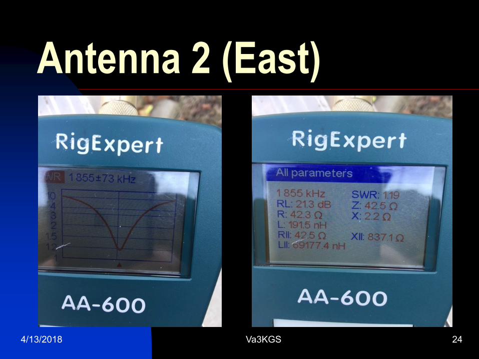
Antenna 2 (East)
4/13/2018 Va3KGS 24
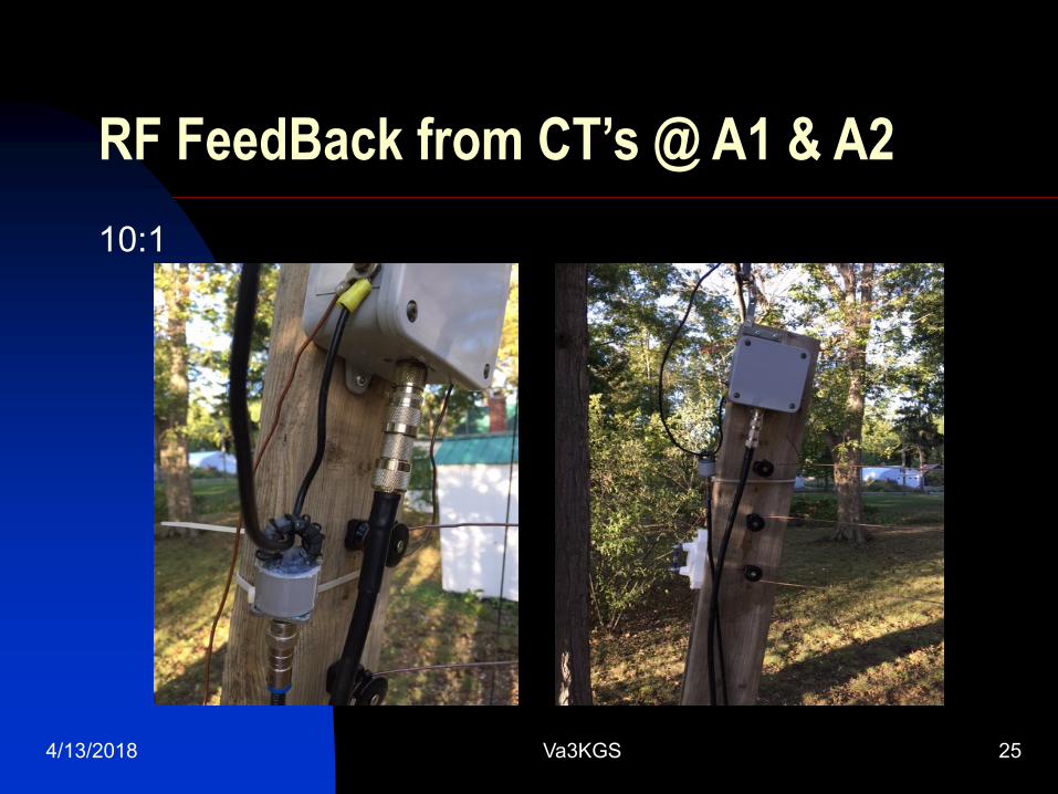
RF FeedBack from CT’s @ A1 & A2
10:1
4/13/2018 Va3KGS 25
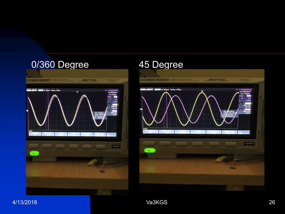
0/360 Degree 45 Degree
4/13/2018 Va3KGS 26
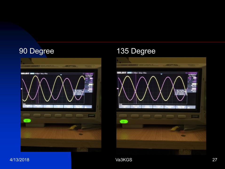
90 Degree 135 Degree
4/13/2018 Va3KGS 27
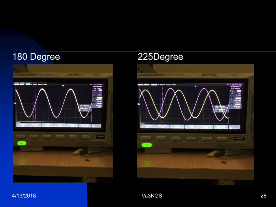
180 Degree 225Degree
4/13/2018 Va3KGS 28
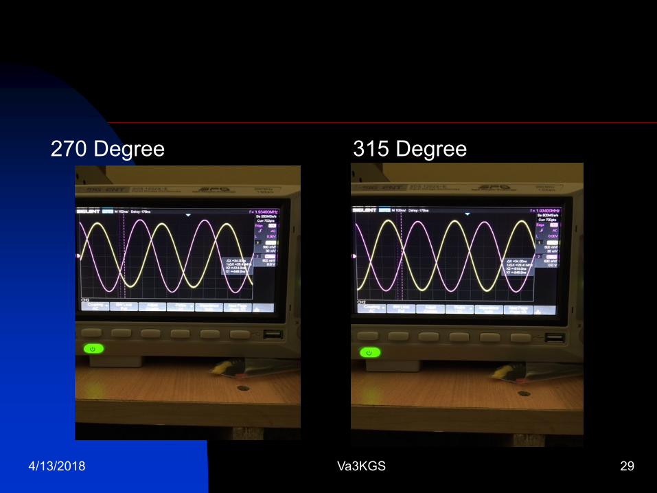
270 Degree 315 Degree
4/13/2018 Va3KGS 29
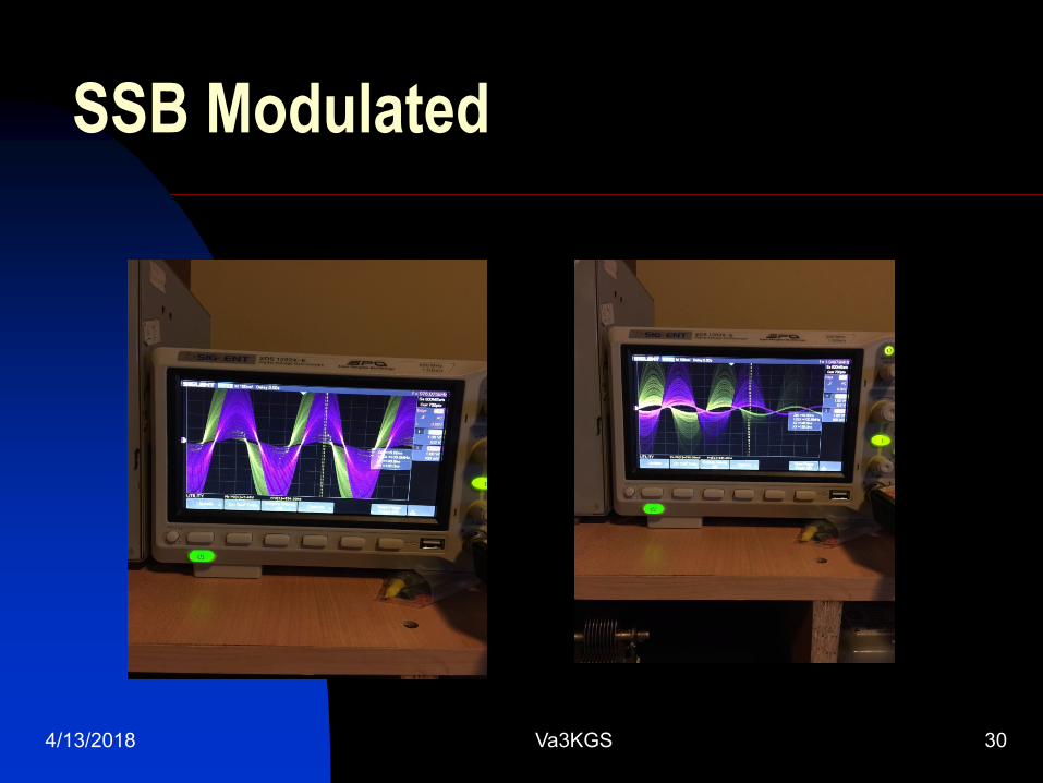
SSB Modulated
4/13/2018 Va3KGS 30

4/13/2018 Va3KGS 31
Other Things to Consider Mutual Inductance between antenna’s
Testing required to see if there is any reaction between the two antenna’s. I suspect that there would not be any interaction as there is no common ground connection using the FCP Design.
Counterpoise mounting height above ground.
Both counterpoises are 6-8 feet above ground.
Tuning was done on the counterpoise portion, not the vertical wire.
Keep Counterpoise away from metal objects as much as possible. ie Tower, Chain Link fence, Eavestroughs, etc…
Other Things to Consider, Cont’d
Support system for wire antenna’s
#12awg (19 Strand) insulated wire, reinforced string (parachute), Egg and standoff insulators, springs.
Boat steering pulley’s work well.
Above ground, or underground installation using conduits for cable routing.
4/13/2018 Va3KGS 32
4/13/2018 Va3KGS 33
Results from this Design
2017 CQWW 160m SSB -100W SO UA
Used single vertical wire with 7 raised radials
Placed; 2nd Canada; 6th NA; 27th World
2017 CQWW SSB (160m) -100W SO UA
Used 2 160m vertical FCP & Switchbox
Placed; 1st Canada; 1st NA; 9th World
2018 CQWW 160M SSB -100W SO UA
Used 2 160m vertical FCP & Switchbox
(score has not been released yet)
4/13/2018 Va3KGS 34
References
ON4UN’s Low-Band Dxing, by J Devoldere, 5th
Edition 2015
The ARRL Antenna Book, 21st Edition 2007
“Steerable Arrays for the Low Bands” by B. Alexander
W5AH, The ARRL Antenna Compendium Volume 2
1989
“Broadband Steerable Phased Arrays” by RC
Fenwick K5RR & RR Shell PhD, QST April 1977
Guy Oliver www.K2AV.com