Embed Size (px)
Citation preview
[Page 805]U. S. DEPARTMENT OF COMMERCE NATIONAL BUREAU OF STANDARDS
RESEARCH PAPER RP946
Part of Journal of Research of the National Bureau of Standards, Volume 17, [pp. 805-839]December 1936
THE VALUE OF GRAVITY AT WASHINGTON
By Paul R. Heyl and Guy S. Cook
ABSTRACT
An absolute determination of the value of gravity in the constant-temperature room in the second subbasement ofthe East Building of the National Bureau of Standards has given the value 98.08 cm/sec2. This determination wascarried out with pendulums of fused silica, and special attention was directed to the flexure correction
CONTENTSPage
I. Introduction ----------------------------------------------------------------------------------------------------------------8051. Purpose of the work--------------------------------------------------------------------------------------------------8052. Previous absolute determinations of gravity --------------------------------------------------------------------8063. Plan of the present determination----------------------------------------------------------------------------------806
II. The observing room -----------------------------------------------------------------------------------------------------807III. The pendulum apparatus -----------------------------------------------------------------------------------------------807
1. The pendulums--------------------------------------------------------------------------------------------------------8072. The supporting apparatus and vacuum case----------------------------------------------------------------------8143. The knife-edges-------------------------------------------------------------------------------------------------------816
IV. Measurement of length -------------------------------------------------------------------------------------------------8161. The standard scale----------------------------------------------------------------------------------------------------8162. The microscopes------------------------------------------------------------------------------------------------------8183. The comparator -------------------------------------------------------------------------------------------------------8184. Methods employed ---------------------------------------------------------------------------------------------------819
V. Measurement of time ----------------------------------------------------------------------------------------------------8211. The clock --------------------------------------------------------------------------------------------------------------8212. The time-signal system ----------------------------------------------------------------------------------------------8213. Method of observing-------------------------------------------------------------------------------------------------8224. Corrections ------------------------------------------------------------------------------------------------------------823
(a) Clock rate --------------------------------------------------------------------------------------------------------823(b) Temperature -----------------------------------------------------------------------------------------------------823(c) Motion of the support ------------------------------------------------------------------------------------------823(d) Damping ---------------------------------------------------------------------------------------------------------824(e) Residual air ------------------------------------------------------------------------------------------------------825(f) Compressibility of the pendulum -----------------------------------------------------------------------------826(g) Flexure of the pendulum---------------------------------------------------------------------------------------827(h) Amplitude--------------------------------------------------------------------------------------------------------828(i) Imperfections of the knife-edge-------------------------------------------------------------------------------828
VI. Results --------------------------------------------------------------------------------------------------------------------831VII. The Potsdam determination ------------------------------------------------------------------------------------------838

THE VALUE OF GRAVITY AT WASHINGTON
2
I. INTRODUCTION
1. PURPOSE OF THE WORK
The work herein described was undertaken by the National Bureau standards at the request of the U. S. Coast andGeodetic Survey, in order to obtain by absolute measurement the value of gravity at the base station of the Survey inWashington. Prior to this work the value adopted by the Survey had rested upon relative comparisons with theabsolute-gravity station at Potsdam, Germany. Several [806] such comparisons had given results for the Survey’s oldbase station at 205 New Jersey Avenue SE., varying by as much as 9 parts in a million. In 1900 a direct connectionof that station with Potsdam and other stations in Europe was made by G. R. Putnam. The value obtained forWashington was 980.112. More recently a connection was made with Ottawa, Canada, which had an independentconnection with Potsdam, and the value obtained for Washington was 980.117. Again, when Dr. F. A. VeningMeinesz, of Holland, brought his gravity-at-sea apparatus to this country the value he found for Washington was980.121. In view of these varying results it was felt that the Survey’s adopted value of 980.112 was probably toosmall, and that an absolute determination at Washington should be undertaken.
During the progress of this work a new direct connection with Potsdam was made in 1933 by Lt. Brown of theSurvey. His result, calculated in terms of the old station, which had then been abandoned by the Survey, was980.118.
The National Bureau of Standards was interested in such a determination on its own account also, as the value ofg enters into absolute electrical determinations such as that of the ampere by the current balance.
2. PREVIOUS ABSOLUTE DETERMINATIONS OF GRAVITY
Since the publication in 1906 of the result of the absolute determination of gravity at Postdam that station bycommon consent has been the accepted international base. The Potsdam value superseded all previous results such asthose obtained in Austria and in Italy, and was regarded as the most precise and authoritative figure that had beenobtained up to that time.
For this there was a special reason. All earlier determinations had involved an unrecognized error, arising fromthe flexure of the pendulum while swinging. Attention had been called to this point on purely theoretical grounds byC. S. Pierce1 as early as 1884, but this calculated correction was so large as to seem incredible.
Ten years later the importance of this correction had been recognized by Helmert, whose calculations indicatedthat this error, while not as great as supposed by Pierce, was still to be regarded as one of the major corrections to beapplied to the time of the swing. In the case of a rather flexible pendulum which had been newly constructed butnever used, Helmert found by his formula a correction of as as much as 366 parts in a million in the value, of g. For apendulum that had been actually used for gravity determinations in France, Helmert calculated the flexure correctionto be 18 parts per million.2
The recognition of the importance of this correction caused Helmert to give special attention to this point in thePotsdam determination of gravity. This work, begun in 1898, was carried out by Kühnen and Furtwängler underHelmert’s supervision. The published report, dated 1906, fills a large volume.
3. PLAN OF THE PRESENT DETERMINATION
There appears as yet to be no better method available for the absolute determination of gravity than that of thereversible pendulum. [807]
Study was given to other possibilities, such as the ring pendulum of Mendenhall,3 but none of these seemedsufficiently promising to be worthy of adoption.
Precision of length measurements would appear to call for as long a pendulum as possible, but this at present isabout 1 meter. The use of a longer pendulum was felt to be inadvisable in view of the fact that the technique of
1 U. S. Coast and Geodetic Survey, Report for 1884 Appendix 16.2 Helmert, Beiträge zur Theorie des Reversionspendels, p. 15 and 28, Potsdam, (1898).3. Mendenhall, , Memoirs of the National Academy of Sciences, X, 1st Memoir (1905).

THE VALUE OF GRAVITY AT WASHINGTON
3
measurement of lengths of 4 or more meters, especially in a vertical position, as is necessary in pendulum work, isnot yet sufficiently perfected to give the precision that can be obtained with length of 1 meter.
There is recorded4 the use of a pendulum 21 meters long, but the precision attained in the length measurementswas only 0.1 mm, about 1 part in 200,000, whereas with a length of 1 meter a precision of 1 part in a million can bereached. It is to be said, however, that the disturbances arising from the imperfections; of the knife-edge, which (aswill appear later) are serious, theoretically should diminish as the pendulum is made longer. Largely because of theseerrors the time of swing of a pendulum which superficially might appear capable of measurement to a precision muchexceeding 1 part in a million, actually is limited to a precision less than that attainable in length measurements.
Because of the difficulty of measuring a length defined by two knife-edges, and because of the desirability ofusing several different knife-edges with the same pendulum, it was decided to use pendulums of the two-plane type.As was first shown by Bessel, this construction eliminates in theory the correction for radius of curvature of a knifeedge.
One factor of uncertainty in pendulum work has always been the temperature correction. It was therefore decidedto construct the three essential parts of the apparatus-the pendulum, the standard scale, and the backbone of thecomparator-all of fused silica, thus rendering the temperature correction almost negligible.
II. THE OBSERVING ROOM
For the observing room there was available the constant-temperature vault of the National Bureau of Standards.This vault is that was used in the recent redetermination of the constant of gravitation.5 It contained a large and asmall room. The clock was installed in the large room and the pendulum in the small room. An opening about 30 cmsquare in the partition wall allowed the observer at the pendulum to see the clock dial when necessary.
III. THE PENDULUM APPARATUS
1. THE PENDULUMS
The form of pendulum adopted was dictated by the nature of the material used (fused silica) and was of necessitysimple. It was an approximation to a uniform straight rod supported at one end, for there is a second point of supportwith the same time of swing, situated at a point two-thirds of the distance to the other end of the rod. [808]
Each pendulum was made of a tube of fused silica. Four such pendulums were constructed, with differentdiameters to give varying flexibilities. To determine the flexibility, the pendulum was supported at two points nearits ends, and a weight applied at the center. The bending was too small to be measured directly, but was determinedby observing with a telescope the image of a distant scale reflected in a mirror attached to the end of the pendulum.In order to compare the flexibilities of the different pendulums the quantity Qµ/EI was calculated, in which
Q = Cross sectional area of the tube.µ = Density,E = Young’s modulus,I = Moment of inertia of cross section.
The silica tubes of which the pendulums were made were not perfectly uniform in cross section, but the abovedescribed procedure will give average values of EI and of Qµ (the mass per unit length). Let D be the distancebetween the points of support and F the weight applied. Then, since the bending is very small, we have at a pointdistant x from the point of application of F:
4 A. A. Ivanov, Annals of the Central Bureau of Weights and Measures, 11-12, Leningrad. (1916-18.) (In Russian.)5 BS J. Research 5, 1243 (1930) RP256.
THE VALUE OF GRAVITY AT WASHINGTON
4
( )
2
2
22
Bending moment 2 2EI
2 2 2 4
F Dx
d y
dx EI
dy F Dx x FDx x
dx EI EI
− = =
= − = −
The constant of integration is zero since dy/dx = 0 if x = 0, i. e., at the point of application of F.At the end of the pendulum where the mirror was mounted x is nearly D/2. At this point:
observed angular displacement
2
dy
dxα= =
We have then:
2
1 16
EI FD
α=
Table 1 gives the data necessary for the calculation of Qµ/EI. The values of the relative flexibility in the lastcolumn are merely numbers proportional to Qµ/EI. In measuring the value of α the distance from mirror to scale wasfrom 1,000 to 1,300 cm.
TABLE 1. —Properties of pendulums
Pendulumnumber
Outsidediameter
Insidediameter
D Mass Qµ F α 1/EI Qµ/EI×1012 Relativeflexibility
cm cm cm g g/cm Dynes Radians1 4 3.4 153.6 1,130 7.4 6.86×10⁵ 0.000 24 2.4×10⁻¹³ 1.8 1.002 4.5 3.4 154 1,927 12 .5 6.86×10⁵ 0.000 13 1.3×10⁻¹³ 1.6 .893 5 3.6 161 3,620 22. 5 2.24×10⁶ 0.000 17 4.7×10⁻¹⁴ 1.1 .61
4 7 5.8 157.5 3,532 22.7 3.43×10⁶ 0.000 11 2.1×10⁻¹⁴ .5 .28
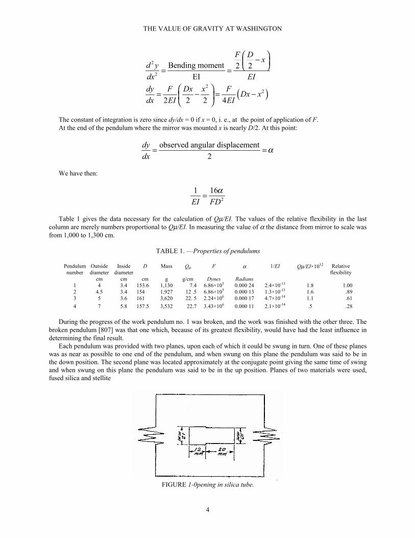
During the progress of the work pendulum no. 1 was broken, and the work was finished with the other three. Thebroken pendulum [807] was that one which, because of its greatest flexibility, would have had the least influence indetermining the final result.
Each pendulum was provided with two planes, upon each of which it could be swung in turn. One of these planeswas as near as possible to one end of the pendulum, and when swung on this plane the pendulum was said to be inthe down position. The second plane was located approximately at the conjugate point giving the same time of swingand when swung on this plane the pendulum was said to be in the up position. Planes of two materials were used,fused silica and stellite
FIGURE 1-0pening in silica tube.

THE VALUE OF GRAVITY AT WASHINGTON
5
For the purpose of attaching the planes to the pendulum, openings of the size and shape shown in figure 1 werecut through both sides of the silica tube. Through the 10- by 20-mm opening was inserted a block (of silica orstellite) of that cross section and long enough to project slightly on each side of the tube. One face of this block wasworked optically flat and furnished the plane by which the pendulum rested upon the knife-edge. The knife-edge inits mounting was inserted through the 12- by 12-mm opening, which allowed sufficient room for the swinging of thependulum.
The large 20-mm faces of the block were polished, but not to the same degree of flatness as the lower face. In thestellite blocks these faces served directly as mirrors for observing the flash signals in measuring the time of swing.With the silica blocks it was found advisable to attach small silvered glass mirrors to these faces.
In addition, the stellite blocks carried on both 20-mm faces a set of fine ruled lines as shown in figure 2, wherethe blocks are shown removed from the pendulum with their optically flat faces B, B in contact. While pressedclosely together in this position the distance between the horizontal lines was determined for later use in measuringthe length of the pendulum.
An attempt to rule such lines on the fused-silica blocks was not encouraging. This material does not take a ruledline well, the edges of the groove being ragged and irregular. Others have found this difficulty and have attempted toovercome it by platinizing the silica surface and ruling lines through the platinum film only. Our experience with thishas been that the lines are of nonuniform excellence, good in spots and ragged in others, due probably to a lack ofuniformity in adhesion or thickness of the platinum film. For this reason we [810] adopted an indirect method ofmeasuring the distance between silica blocks in the pendulum, which will be described later.
When the blocks were in place in the silica tube the mirror face and the set of measuring lines could be seenthrough openings cut in tubes as shown in figure 3.
At the end faces of all the blocks vertical lines were ruled marking the median plane of the block. In setting upthe pendulum these lines were so adjusted that their prolongations intersected that of the knife-edge, which could bedone to 0.1 mm. The error in the value of g arising from a variation in this adjustment is not capable of calculation. Itis irregular and seems to depend upon a variation in properties of the different places in the plane which may be incontact with knife-edge. The experience of the U. S. Coast Survey has led them attach special importance to thispoint in the construction of their instruments for relative gravity work. By the use of a mechanical device for raisingand lowering the pendulum the Coast Survey found that the knife-edge could be set repeatedly on the same positionon the plane, and relative values of g accurate to 1 part in a million could be obtained. Without this precaution theresults varied widely and irregularly.
FIGURE 2.—Stellite blocks with ruled lines
The blocks required mounting in the pendulum with the faces B, B parallel. This was attained by an opticalmethod. The silica pendulum tube was mounted in a brass tube or jacket and held in place by setscrews with leadpads. This brass jacket was less 100 cm long and enclosed that part of the silica tube between the places of support,allowing easy access to the holes and the blocks. The brass jacket was provided at each end with a circular ring orcollar, on which the jacket and its contained silica tube could rotated on a support consisting chiefly of two parallelrods. This arrangement made it possible to rotate the slightly irregular silica tube about a definite axis (fig. 3).
The silica tube was adjusted by means of the setscrews so as to be as nearly as possible concentric with the brassjacket. One of blocks was then inserted in place and held by wooden wedges. A miniature 5-volt lamp was placed atthe end of the silica tube and the image of the filament reflected from the face B of the block was observed with atelescope as the tube and brass jacket were rotated together. The image described a circle, showing that the plane Bwas not perpendicular to the axis of rotation.
Observation having indicated where the silica surfaces against which the face A, A rested needed grinding off, theblock was removed and a little grinding done by means of a hand tool and a fine grade of carborundum powder. To

THE VALUE OF GRAVITY AT WASHINGTON
6
facilitate this process the silica bearing surfaces were cut so as to offer a three-point bearing for the block, one silicasurface being cut out slightly at its center and the other at its ends. The block was then replaced and anotherobservation taken. It was found possible by repeated trials to adjust the block so that the reflected image remainednearly stationary on rotating the tube. The precision of this adjustment is indicated by the following figures.
FIGURE 3.—Brass jacket supporting silica tube.
[811] The lamp filament was about 2 mm long, and as the tube was rotated the radius of the circle described bythe image of the filament was in no case greater than about one-fifth the length of the filament. The distance fromtelescope to mirror was, at one end of tube, about 120 cm, and at the other end about 170 cm. The maximumdeparture from parallelism indicated by these figures is about 0.01º.
A departure from parallelism in the direction of the swing of the pendulum, perpendicular to the knife-edge, is ofno importance. A departure in the direction of the knife-edge reduces the problem to that of the horizontal pendulum.As shown by Webster (Dynamics, p. 252) the length of the equivalent simple pendulum is increased in the ratio 1/cosθ, where θ is the angle made by the knife-edge with the horizontal. When θ = 0.01°,cos θ = 0.999 999 99, and the correction is negligible.
Without disturbing the pendulum in its jacket the same process was carried out with the second block in itsproper place. Each face B was thus set perpendicular to the same straight line, the joint axis of rotation of the tubeand jacket, and hence the two faces B were parallel.
The blocks, held in position by wooden wedges, were then fastened in place by a suitable cement, none of whichwas allowed to reach the surfaces A, A. The best cement found for joining stellite to fused silica was red sealing wax.For joining silica to silica the best cement is fused chloride of silver, which melts at a moderate temperature.
It was possible to check the parallelism of the faces B,B after cementing by observing the reflection of the 5-voltlamp from one block with the other in place, there being sufficient space above and below the blocks to allow of this.
The next adjustment of the pendulum was that for equal times of on the two planes of support. To attain this, thesilica tube, originally longer than necessary, was shortened by cutting off successive slices from its lower end, andfinished by grinding slightly. A very accurate adjustment is thus easily possible. The necessity for this adjustmentarises from the fact that the location of the center of gravity of the pendulum is not capable of determination withgreat accuracy. This defect may be counterbalanced by a sufficiently close adjustment of the two times of swing. Thenecessary approximation to equality of times is easily calculated.
The time of swing τ of the simple pendulum equivalent to a reversible pendulum of times of swing T1 and T2 isgiven by the formula:
1
2 21 2 22
1 2
T h T h
h hτ
−=
−! (1)
where h1 and h2, are the distances of the center of gravity from the two planes of support. If 1 is the distance betweenthese two planes, h2 = l — h1 and eq 1 becomes
1 1
2 2 21 2 12
12
T h T l T h
h lτ
− +=
−! (2)
Differentiating and reducing:

THE VALUE OF GRAVITY AT WASHINGTON
7
( ) ( )( )
2 2 22 2
21 1 2
d T T l
dh h h
τ −=
−
[812] If τ is equal to (T1 + T2)/2, as will essentially be the case if τ, T1 and T2 are each nearly unity,
( )( )
2 12
1 1 2
T T ld
dh h h
τ −=
−" (3)
As a numerical example, let l = 1,000 mm, h1 = 700 mm, h2 = 300 mm, and T2 — T1 = 0.0001 second then
1
0.000 000 6d
dh
τ =
Thus an error dh1 of as much as 1 mm in locating the center of gravity would make a difference in the time ofswing of but 6 parts 10 million. As the center of gravity of the pendulum could be readily located to one- or two-tenths of a millimeter an adjustment of times to 0.0001 second is sufficient for our purpose.
The theory of the reversible pendulum requires that the center of gravity shall lie in the plane of the two lines ofsupport. When this is fulfilled other asymmetries in a pendulum of the form used by us, in which there are nointerchangeable weights, are (in a vacuum) self-eliminating. This adjustment was tested as was done in the Potsdamdetermination, after the pendulums were adjusted to equality of times of swing, by hanging each pendulum on aknife-edge with fine plumb lines passing close to the ends of the blocks. When the lines on the upper block coincidedwith the plumb lines, those on the lower block were in no case more than 0.2 mm out of line. A departure of 0.2 mmin 1,000 mm is geometrically of no importance as the cosine of the angle is 0.999 999 98.
The temperature coefficient of expansion of fused silica was taken to be 0.000 000 6, and this will of course bethe coefficient for a pendulum with silica blocks. With stellite blocks in a silica pendulum it is a more complicatedquestion. The coefficient of expansion of stellite varies with different samples from 0.000 011 to 0.000 015. The.value of 0.000 013 was assumed in this case.
Assuming the blocks to be always be in contact with the silica bearing surfaces, and any differential. expansionalong the 2 cm width of the block to be taken up by the cement, we may calculate the net change of length betweenthe planes of support B. Taking the distance between these planes to be approximately 100 cm we have:
104×0.000 000 6 - 4×0.000 013 = 0.000 062 - 0.000 052 = 0.000 010
Dividing by the length, 100 cm., we obtain for the coefficient of expansion 0.000 000 1, about one-sixth that ofan all-silica pendulum. Assuming the value of 0.000 011 for the coefficient of stellite, the coefficient of thependulum becomes 0.000 000 18.
The temperature coefficient of time of swing will not be the same as that of linear expansion. For an all-silicapendulum, since the time of swing is proportional to the square root of the length, the time coefficient will be one-half the length coefficient, or 0.000 000 3. For a silica pendulum with stellite blocks the matter is not quite so simple.
Since the mass of a stellite block is small compared to that pendulum (from 4 to 8 percent) we may (as far asmass is concerned) [813] assume the pendulum, swung in either position, to be a uniform rod pivoted at a distance hfrom its center of gravity. The radius of gyration of the pendulum, about an axis through its center of gravity bedenoted by k. For a uniform rod, k2 = L2/12, where L is the total length of the rod. The time of swing in eitherposition will be given by
2 2 2 2 22
12
k h LT h
g h g h
π π += = +
Differentiating with respect to the temperature t:
THE VALUE OF GRAVITY AT WASHINGTON
8
( ) 22 2
2 2
12 2 12
12
dL dhh L Ld T dhdt dt
dt g h dt
π × − ×
= +
Since T is nearly 1 second:
2 2
21
2 6 12
dT L dL dh L
dt g h dt dt h
π = + −
" (4)
In all the pendulums we have approximately
L = 155 cmh = 70 cm (down)h = 30 cm (up)
In the down position we have, therefore,
2
2
0.376
0.4112
155 0.000 000 6 0.000 093
72 0.000 000 6 2 0.000 013 0.000 017
L
h
L
hdL
dtdh
dt
=
=
= × =
= × − × =
Substituting in eq 4
0.000 000 22dT
dt= " (5)
For the up position
2
2
30 cm
0.866
2.2212
32 0.000 000 6 2 0.000 013 0.000 007
h
L
h
L
hdh
dt
=
=
=
= × − × = −
[814] Substituting in eq 4

THE VALUE OF GRAVITY AT WASHINGTON
9
0.000 000 45dT
dt= "
(6)
As a check on eq 4 we may calculate the time coefficients for an all-silica pendulum in the two positions. In thedown position dh/dt = 70×0.000 000 6 = 0.000 042 and in the up position dh/dt = 30×0.000 000 6 = 0.000 018. Theother quantities remain the same. Substituting in eq 4 the coefficient in each position comes out 0.000 000 29, asatisfactory agreement with 0.000 000 3, obtained by taking half of the coefficient of linear expansion.
The temperature corrections to the time of swing given by eq 5 and 6 were applied to each time of swing, downand up, as these were obtained, and the corrected values of T1 and T2 thus obtained were used in eq 1 to calculateτ 2 and finally g. No correction of h1 or h2 for temperature is necessary in eq 1, as the h values need be known only tofour figures to insure a value of g accurate to 1 point in a million.
2. THE SUPPORTING APPARATUS AND VACUUM CASE
The knife-edge upon which the pendulum swung was mounted in a steel support (later to be described) of such asize that it could pass through the 12-mm-square hole in the pendulum with room enough to spare for a reasonablylarge amplitude of swing. This steel support rested at its ends in notches cut in a heavy brass ring (fig. 4), which inturn was screwed down over a hole in a heavy steel shelf which rested on large cast-iron wall brackets (fig. 5).
FIGURE 4.—Brass ring support for knife-edge.
FIGURE 5.—Steel shelf.
The shelf and bracket supporting the pendulum were made especially massive and rigid in order that any motionof the support arising from the swinging of the pendulum should be as little as possible. The cast-iron brackets,weighing about 50 kg each, were bolted into a large mass of concrete imbedded in the brick wall of the room. Thewall was hollowed out to a depth of about 75 cm, the cavity being made wider as it became deeper, dental fashion.Boards were placed across the cavity, which was about 1 meter square, and bolts set in proper position in one of the

THE VALUE OF GRAVITY AT WASHINGTON
10
boards with their heads in the cavity. The cavity was then filled with concrete. When the boards were removed thebrackets were fitted over the projecting bolts and fastened in place by nuts.
FIGURE 6.—Vacuum case for pendulum.
[815] The steel shelf resting on these brackets was 40 cm square and 4 cm thick, with a circular hole 9 cm indiameter over which the brass ring was fitted. This ring carried two bolts 180° apart which passed loosely throughthe ring and screwed into the steel shelf. There were also two other bolts at 90° from the first pair which screwedthrough the ring and pushed against the shelf. By means of these pulling and pushing bolts the ring and knife-edgecould be levelled.

THE VALUE OF GRAVITY AT WASHINGTON
11
A departure from level would theoretically alter the time of swing. If θ is the angle made by the knife-edge withthe horizontal the length of the equivalent simple pendulum will be increased in the ratio 1/cos θ. The level usedwould indicate a difference of 0.001 radian, of which the cosine differs from unity by 5 parts in 10 million.
Apart from this geometrical effect there is the possibility of disturbing the time of swing by increasing thepressure on one-half of the knife-edge and decreasing it on the other. A number of experiments were made to test thispoint. Thin slips of sheet metal were inserted under one end or the other of the knife-edge, by which the level couldbe altered by steps of 0.001 radian. With differences of as much as 0.004 radian or more on either side there wasalways a consistent diminution of the time of swing, but for angles differing 0.001 or 0.002 from the bubble level theeffects were entirely regular and of the same order of magnitude as were encountered on different settings at thebubble level.
The vacuum case was of brass tubing 16 cm inside diameter, find made in three sections (fig. 6). The centralsection was bolted at its upper end to the underside of the steel shelf, and to its lower was bolted the bottom section.The upper section rested by its weight on the upper side of the steel shelf. Joints were made air-tight by a rosin-beeswax mixture.
The central and lower sections of the vacuum case were never moved from position, but the upper section had tobe lifted and swung away every time the pendulum was to be reversed. For this purpose a pulley arrangement wasprovided.
Glass windows were provided in the pendulum case wherever necessary such as where flash observations forcoincidences were to be made, or where the amplitude of swing was to be measured. In the early stages of the workthe amplitude was measured by observing lower part of the pendulum by means of a traveling microscope. [816]
Later this measurement was made by a beam of light reflected from the upper stellite or silica block to a scaleabout a meter away.
Outlets were provided in the central section for the pump connection and for the pressure gage. A gage of theMcLeod type was used. Another outlet in the bottom section was provided with a glass stopcock which served as apneumatic starter for the pendulum. In the early stages of the exhaustion puffs of air were admitted through thisoutlet until a suitable amplitude was obtained. The stopcock was then closed and the exhaustion finished to less than0.1 mm.
Early in the work a quantity of radioactive sand was placed in the bottom of the vacuum case to provide againstelectrification of the pendulum. On comparing results obtained before and after introducing the sand there was noevidence that it was needed. However, it was allowed to remain in the case for the whole duration of the work.
3. THE KNIFE-EDGES
Several materials were tried for knife-edges—fused silica, agate, stellite and steel. The behavior of these differentmaterials will be later described.
The silica and agate edges were mounted in a groove in a bar of steel, and held in place either by cement orclamping pieces of metal. The stellite and steel edges were made in one piece, long enough to rest in the grooves inthe brass ring and heavy enough to bear the weight of the pendulum, about 1 cm wide and high. The working edgewas ground to an angle of about 135°, and was cut away for a space of from 1 to 2 cm in the middle to preventwalking of the pendulums.
No knife-edge can be ground to a geometrically perfect edge nor is it advisable that it should be. On such an edgeany finite load, however small, would produce an infinite pressure and a consequent breakdown of the edge. InZeitschrift für Instrumentenkunde, January 1932, Schmerwitz describes a method for measuring the radius ofcurvature of a knife-edge. We have constructed an apparatus such as was used by Schmerwitz and find that hismethod can be used in practice with an accuracy of about 15 percent. Values for the radius of knife-edges, to bementioned later, were obtained in this way.
IV. MEASUREMENT OF LENGTH
1. THE STANDARD SCALE
The standard scale was constructed of a piece of fused silica tubing about 18 mm in diameter and a little over 1 mlong. Near each end the tube was cut half way through and a flat silica plate fastened by fusion in the diametral plane

THE VALUE OF GRAVITY AT WASHINGTON
12
of the tube (fig. 7). These plates were about 12 mm wide and were so placed that the centers were about 995 mmapart.
FIGURE 7.—Cross section of silica scale.
Silica scales have been constructed and observed over a considerable period of time at the National PhysicalLaboratory, in England, where it was found, as we have also observed (section III: 1), that silica does not receive orpreserve graduations well, the material tending to flake off at the scratches. For this reason the National PhysicalLaboratory platinized portions of the silica surface and ruled lines through the thin coat of platinum withoutscratching the silica beneath.
This plan was tried by us, but difficulty was found in obtaining a coat of platinum that would give good lines atall places. Usually spots could be found upon which excellent lines could be ruled, but at other places it was notpossible to do so well. For this reason a different plan was finally adopted.
The Hanovia Chemical and Manufacturing Co. constructed for us a scale with short pieces of tungsten rod fusedinto the flat silica plates. To these tungsten rods pieces of sheet platinum about 1 mm thick were silver-soldered.After polishing the faces of the platinum pieces it was found possible to rule excellent lines upon them. Lines wereruled approximately 0.25 mm apart, giving lengths varying from about 994 to 999 mm. This scale was calibrated bycomparison with a standard meter bar in the Length Section of the National Bureau of Standards. A copy of thereport of these measurements follows.
INTERVALS ON PLATINUM-FACED SILICA SCALE
IDENTIFICATION NO. 2(Graduated by National Bureau of Standards, Division II-1)
This bar, when supported at the two neutral points, has been compared with the standards of the United States, and the intervals indicated
were found to have following lengths at 20 °C.
Intervals Length (mm)0 to 0 993.98695 to 5 996.486610 to 10 998.9812
Left-end intervals Length Right-end intervals Lengthmm mm
0 to 1 0.2502 0 to 1 0.24981 to 2 .2490 1 to 2 .25042 to 3 .2502 2 to 3 .25033 to 4 .2494 3 to 4 .24954 to 5 .2504 4 to 5 .24945 to 6 .2490 5 to 6 .25006 to 7 .2495 6 to 7 .24777 to 8 .2493 7 to 8 .25408 to 9 .2503 8 to 9 .24979 to 10 .2475 9 to 10 .2491
The above values are not in error by more than 0.0010 mm.
The observations were taken at a mean temperature of 28.30° C and in reducing to 20° C the coefficient of expansion of the silica bar was
assumed to be 0.000 000 6 per degree centigrade.
[818] The scale was mounted for protection in a brass tube with openings to permit the graduated portions to beseen. Since the scale was to be used in a vertical position the brass tube was so arranged that the scale could be
THE VALUE OF GRAVITY AT WASHINGTON
13
supported at either the bottom or the top. A series of observations failed to show any observable difference in lengthin the two cases. Calculations indicated that such a change would be a small fraction of 1 micron, and our lengthmeasurements were good only to 1 micron As a matter of convenience, therefore, the scale was always supported atthe bottom.
2. THE MICROSCOPES
Two micrometer microscopes, of the Geneva Society’s make, were employed in this work. Rather a long focus(about 2.5 cm) necessary in order to reach the blocks inside the pendulum tubes. These microscopes were tested bythe Length Section of the National Bureau of Standards for periodic and progressive errors and for average value ofone revolution of the drum, which carried 100 divisions. In each case the error was found to be less than one divisionon the drum. Each microscope was adjusted so that one revolution equalled 100 µ to better than 1 part in 1,000. Thescopes were provided with vertical illumination.
3. THE COMPARATOR
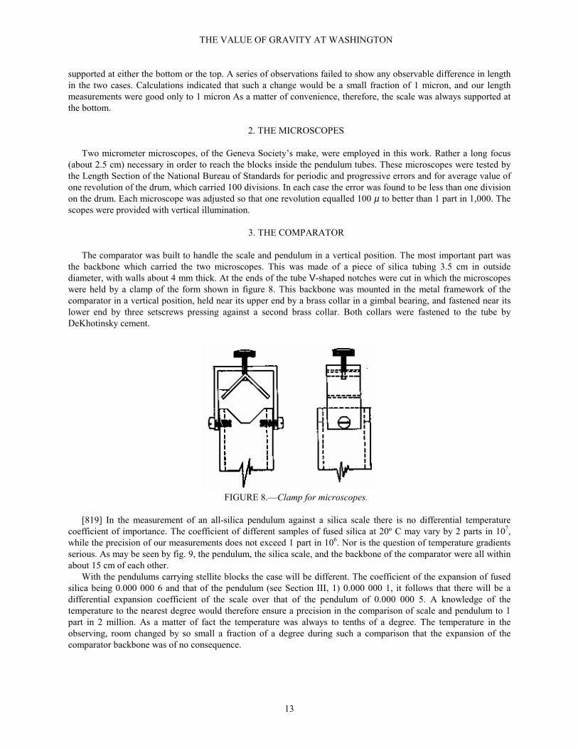
The comparator was built to handle the scale and pendulum in a vertical position. The most important part wasthe backbone which carried the two microscopes. This was made of a piece of silica tubing 3.5 cm in outsidediameter, with walls about 4 mm thick. At the ends of the tube V-shaped notches were cut in which the microscopeswere held by a clamp of the form shown in figure 8. This backbone was mounted in the metal framework of thecomparator in a vertical position, held near its upper end by a brass collar in a gimbal bearing, and fastened near itslower end by three setscrews pressing against a second brass collar. Both collars were fastened to the tube byDeKhotinsky cement.
FIGURE 8.—Clamp for microscopes.
[819] In the measurement of an all-silica pendulum against a silica scale there is no differential temperaturecoefficient of importance. The coefficient of different samples of fused silica at 20º C may vary by 2 parts in 107,while the precision of our measurements does not exceed 1 part in 106. Nor is the question of temperature gradientsserious. As may be seen by fig. 9, the pendulum, the silica scale, and the backbone of the comparator were all withinabout 15 cm of each other.
With the pendulums carrying stellite blocks the case will be different. The coefficient of the expansion of fusedsilica being 0.000 000 6 and that of the pendulum (see Section III, 1) 0.000 000 1, it follows that there will be adifferential expansion coefficient of the scale over that of the pendulum of 0.000 000 5. A knowledge of thetemperature to the nearest degree would therefore ensure a precision in the comparison of scale and pendulum to 1part in 2 million. As a matter of fact the temperature was always to tenths of a degree. The temperature in theobserving, room changed by so small a fraction of a degree during such a comparison that the expansion of thecomparator backbone was of no consequence.

THE VALUE OF GRAVITY AT WASHINGTON
14
FIGURE 9.—Comparator.
For the general structure of the comparator a comparatively brief description will suffice. Its general appearanceis shown in figure 9. The pendulum and scale were supported side by side by means of short arms projecting radiallyfrom a vertical rod. By turning this rod either pendulum or scale could be brought into view in the microscopes.Focusing was done by moving this vertical axis forward or backward at each end by a screw motion, the microscopesremaining fixed in position. The vertical axis could also be raised or lowered as desired.
The length of the silica backbone was adjusted so that measurement lines on the pendulum appear near the centerof the field of each microscope. To allow for slight differences in the length of the different pendulums thin sheets ofcopper or aluminum were introduced between the microscope barrel and the notch in which it rested in the silicatube.
The pendulum was supported in the comparator at its upper plane upon a brass strip with a small verticalprojection at its center, thus allowing the pendulum freedom of motion in two directions for purposes of alignment.

THE VALUE OF GRAVITY AT WASHINGTON
15
At its lower end the pendulum was held by a rubber band against two setscrews in a Y-shaped support. By meansthese screws and the upper pivot support the pendulum could be adjusted to the vertical. In addition, coarseadjustment was possible by rotating separately the projecting radial arms carrying the pendulum about the centralaxis of the comparator.
4. METHODS EMPLOYED
The measurement of the distance between the planes was most easily carried out with the stellite blocks. Beforeinserting the blocks in the pendulum they were pressed together at their optically flat surfaces and the distancebetween the ruled lines determined (fig. 2). After the blocks were set in place measurements were made on both[820] the front and back sides to eliminate any lack of parallelism. A typical example of such a length measurementfollows:
Back position. Temperature 24.3º
Scale distance used, 997.9854 mm at 20.0º
Micrometer microscope readings, mm:
Pendulum Scale
Lower Upper Lower Upper
0.6467 0.3550 0.7101 0.3804
.6465 .3544 .7102 .3804
.6467 .3540 .7102 .3804
.6467 .3542 .7100 .3806
.6464 .3548 .7101 .3802
Mean _ _ 0.6466 0.3545 Mean _ _ 0.7101 0.3804
0.3545 0.3804
∆P = 0.2921 ∆S = 0.3297
∆P = 0.2921
Scale-pendulum = 0.0376 mm at 24.3°= 0.0354 at
20.0°Scale = 997.9854 at
20.0°Pendulum = 997.9500 at 20.0° between lines
Correction for lines _ _ _ _ 0.799
Length between planes = 997.151 mm at 20.0°
In the foregoing example the quantity ∆P is the amount to be added to the distance betwen the zero points of themicroscopes to give the distance between the measuring lines on the pendulum, and ∆S is a similar quantity for thescale. By subtraction we obtain the difference between the scale and the pendulum.
In the case of the pendulums provided with silica blocks the measurement of length offers more difficulties. It isnot practicable to rule lines on fused silica (section III, 1) and the first method tried for measuring the distancebetween the planes was Fizeau’s “point and image” method used in end-standard measurements. In this method thepoint of a needle is placed against the plane and the cross wire of the microscope set on the junction of the point andits reflected image. This method offers considerable experimental difficulty. Much depends on the precision offocusing, and as but half the lens is used, an objective of high perfection is required. Berndt-Schultz (Grundlagenund Geräte technischer Längemessungen, page 23) says: “In spite of this, the precision of optical measurements onend-standards is about 5 times less than on line standards * * *. By the use of other objectives the error may be aslarge as 3.5 µ.”
The end-standards spoken of here are the polished faces of the metal bars. Rather unexpectedly, we have foundthat the difficulty is still further multiplied when dealing with transparent material such as fused silica. The samemicroscopes that will give acceptable results on metal faces give abnormally variable results on faces of fused silica.In one case it was observed (through the microscope) [821] that as the needle steadily approached the surface itsimage halted for an instant and then resumed its motion.
THE VALUE OF GRAVITY AT WASHINGTON
16
It being thus out of the question to apply the “point and image” method to fused silica, recourse was had tocontact blocks. Two small blocks of stainless steel were ruled with lines close to their edges as with the stelliteblocks, and the distance between the lines was determined when the blocks were pressed together. By a suitableclamping device one stainless steel block was pressed tightly against each silica block. In this way the problem wasconverted from one of an end-standard to one of a line standard
V. MEASUREMENT OF TIME
1. THE CLOCK
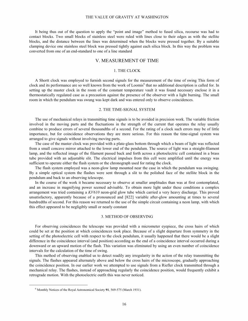
A Shortt clock was employed to furnish second signals for the measurement of the time of swing This form ofclock and its performance are so well known from the work of Loomis6 that no additional description is called for. Insetting up the master clock in the room of the constant temperature vault it was found necessary enclose it in athermostatically regulated case as a precaution against the presence of the observer with a light burning. The smallroom in which the pendulum was swung was kept dark and was entered only to observe coincidences.
2. THE TIME-SIGNAL SYSTEM
The use of mechanical relays in transmitting time signals is to be avoided in precision work. The variable frictioninvolved in the moving parts and the fluctuations in the strength of the current that operates the relay usuallycombine to produce errors of several thousandths of a second. For the rating of a clock such errors may be of littleimportance, but for coincidence observations they are more serious. For this reason the time-signal system wasarranged to give signals without involving moving parts.
The case of the master clock was provided with a plate-glass bottom through which a beam of light was reflectedfrom a small concave mirror attached to the lower end of the pendulum. The source of light was a straight-filamentlamp, and the reflected image of the filament passed back and forth across a photoelectric cell contained in a brasstube provided with an adjustable slit. The electrical impulses from this cell were amplified until the energy wassufficient to operate either the flash system or the chronograph used for rating the clock.
The flash system employed was a neon-glow lamp mounted near the case in which the pendulum was swinging.By a simple optical system the flashes were sent through a slit to the polished face of the stellite block in thependulum and back to an observing telescope.
In the course of the work it became necessary to observe at smaller amplitudes than was at first contemplated,and an increase in magnifying power seemed advisable. To obtain more light under these conditions a complexarrangement was tried containing a KV610 neon-grid glow tube which carried a very heavy discharge. This provedunsatisfactory, apparently because of a pronounced and [822] variable after-glow amounting at times to severalhundredths of second. For this reason we returned to the use of the simple circuit containing a neon lamp, with whichthis effect appeared to be negligibly small or nearly constant
3. METHOD OF OBSERVING
For observing coincidences the telescope was provided with a micrometer eyepiece, the cross hairs of whichcould be set at the position at which coincidences took place. Because of a slight departure from symmetry in thesetting of the photoelectric cell with respect to the clock pendulum, it usually happened that there would be a slightdifference in the coincidence interval (and position) according as the end of a coincidence interval occurred during adownward or an upward motion of the flash. This variation was eliminated by using an even number of coincidenceintervals for the calculation of the time of swing.
This method of observing enabled us to detect readily any irregularity in the action of the relay transmitting thesignals. The flashes appeared alternately above and below the cross hairs of the microscope, gradually approachingthe coincidence position. In our earlier work we attempted to use signals from a Riefler clock transmitted through amechanical relay. The flashes, instead of approaching regularly the coincidence position, would frequently exhibit aretrograde motion. With the photoelectric outfit this was never noticed.
6 Monthly Notices of the Royal Astronomical Society 91, 569-575 (March 1931).
THE VALUE OF GRAVITY AT WASHINGTON
17
In changing the pendulum from the down to the up position it was rotated about its right and left axis, so thatwhat was formerly the front side now became the back. The two positions of swing were denoted by the terms "front-down" and "back-up", respectively
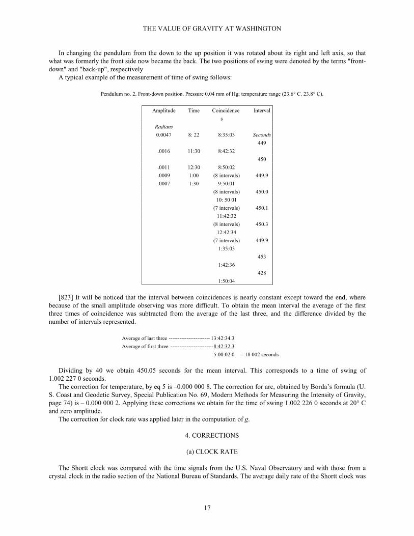
A typical example of the measurement of time of swing follows:
Pendulum no. 2. Front-down position. Pressure 0.04 mm of Hg; temperature range (23.6° C. 23.8° C).
Amplitude Time Coincidence
s
Interval
Radians
0.0047 8: 22 8:35:03 Seconds
449
.0016 11:30 8:42:32
450
.0011 12:30 8:50:02
.0009 1:00 (8 intervals) 449.9
.0007 1:30 9:50:01
(8 intervals) 450.0
10: 50 01
(7 intervals) 450.1
11:42:32
(8 intervals) 450.3
12:42:34
(7 intervals) 449.9
1:35:03
453
1:42:36
428
1:50:04
[823] It will be noticed that the interval between coincidences is nearly constant except toward the end, wherebecause of the small amplitude observing was more difficult. To obtain the mean interval the average of the firstthree times of coincidence was subtracted from the average of the last three, and the difference divided by thenumber of intervals represented.
Average of last three ----------------------- 13:42:34.3
Average of first three ------------------------8:42:32.3
5:00:02.0 = 18 002 seconds
Dividing by 40 we obtain 450.05 seconds for the mean interval. This corresponds to a time of swing of1.002 227 0 seconds.
The correction for temperature, by eq 5 is –0.000 000 8. The correction for arc, obtained by Borda’s formula (U.S. Coast and Geodetic Survey, Special Publication No. 69, Modern Methods for Measuring the Intensity of Gravity,page 74) is – 0.000 000 2. Applying these corrections we obtain for the time of swing 1.002 226 0 seconds at 20° Cand zero amplitude.
The correction for clock rate was applied later in the computation of g.
4. CORRECTIONS
(a) CLOCK RATE
The Shortt clock was compared with the time signals from the U.S. Naval Observatory and with those from acrystal clock in the radio section of the National Bureau of Standards. The average daily rate of the Shortt clock was

THE VALUE OF GRAVITY AT WASHINGTON
18
about —0.04 second over the period covered by the results given in this paper. During this period the rate wasremarkably constant, its daily variation seldom reaching the decimal place While it is possible, as Loomis has shown,to obtain a much smaller rate from a Shortt clock this precision was ample for our requirements. Were this rateneglected altogether the error in the value of g would not the exceed 1 part in a million.
(b) TEMPERATURE
The temperature of the pendulum was assumed to be that of the brass vacuum case, as measured by athermometer on the outside of the case. After sealing the case the apparatus was allowed to stand overnight beforeobservations were made. In correcting the time of swing for temperature the values given in tables 5 and 6 for thedown and up positions were used for pendulums in stellite blocks and 0.000 000 3 for both positions of the all-silicapendulums.
(c) MOTION OF THE SUPPORT
Helmert (Beiträge, page 70) gives the mathematical theory of the effect of motion of the support on the time ofswing of a pendulum, quoting an earlier investigation by C. S. Peirce, and confirming his result. If a pendulum ofmass M swinging through an arc θ produces a horizontal elastic displacement of the support,
Mgh
l
θσε
=
[824] in which ε is an elastic constant. Helmert also finds the alteration the equivalent length l of a simpleseconds pendulum to be given the equation:
2' 1
Mghl l
lε = +
From these two equations it follows that the apparent increase in the length of the pendulum
'Mgh
l l ll
σδε θ
= − = =
or
l
l l
δ σθ
=
Since, δ l is very small compared to l, this is equivalent to saying that the pendulum may be regarded asoscillating about a new center elevated by δ l above the moving axis of support.
The correction for the motion of the support thus requires a knowledge of the arc of swing and the displacementof the support. The displacement may be observed directly by an interferometer as is done by the U. S. Coast andGeodetic Survey, or may be calculated by its effect in producing motion in an auxiliary pendulum as was done by thePotsdam observers. In the present work the interferometer method was employed. A small optically flat disk of fusedsilica was mounted by a little wax on one end of the knife-edge, which could be exposed for this purpose by movingthe pendulums slightly to one side.
A specially built interferometer tube carrying a second flat plate and a helium tube for illumination, was mountedon a support independent of the steel shelf that carried the pendulum case. The interferometer tube could be movedback and forth by a screw motion so that the two flat plates could be adjusted to give fringes.
In addition to testing the motion of the knife-edge itself, the test plate was mounted also on the steel strip whichcarried the knife-edge, and on the brass ring.
THE VALUE OF GRAVITY AT WASHINGTON
19
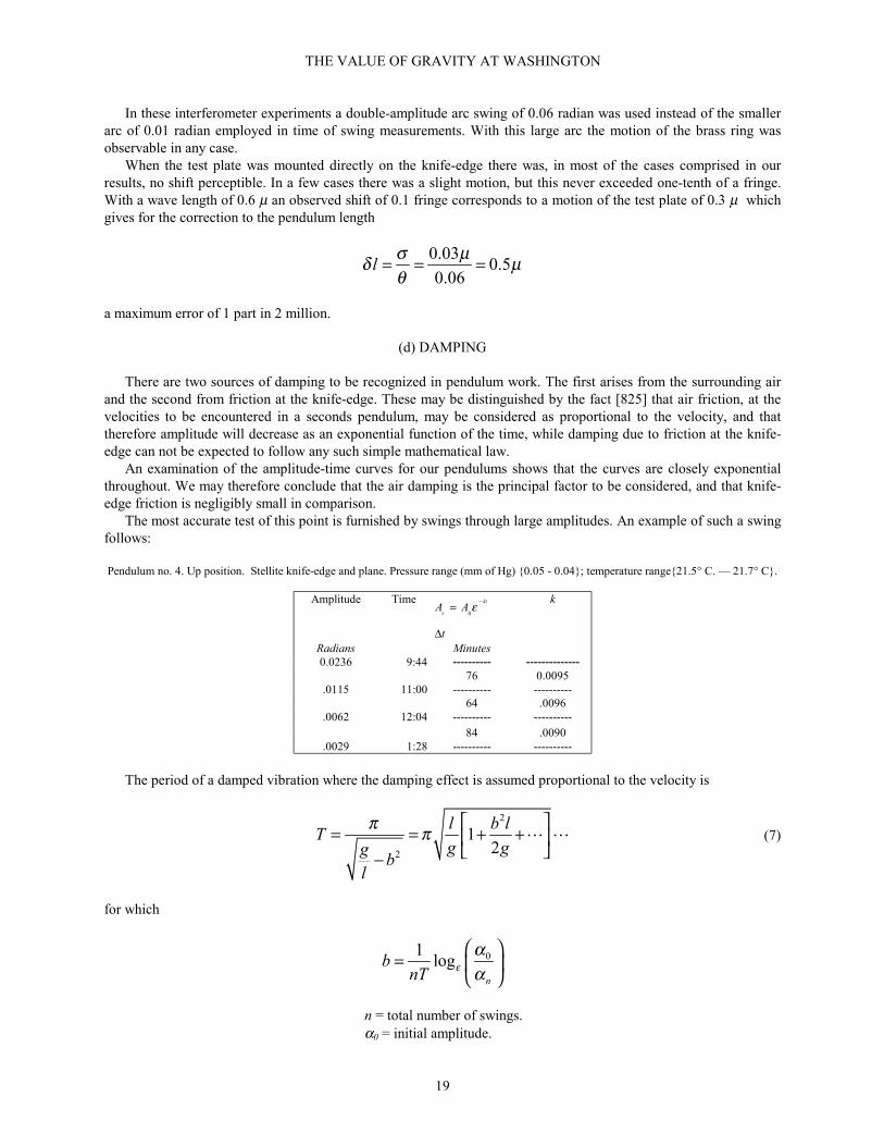
In these interferometer experiments a double-amplitude arc swing of 0.06 radian was used instead of the smallerarc of 0.01 radian employed in time of swing measurements. With this large arc the motion of the brass ring wasobservable in any case.
When the test plate was mounted directly on the knife-edge there was, in most of the cases comprised in ourresults, no shift perceptible. In a few cases there was a slight motion, but this never exceeded one-tenth of a fringe.With a wave length of 0.6 µ an observed shift of 0.1 fringe corresponds to a motion of the test plate of 0.3 µ whichgives for the correction to the pendulum length
0.030.5
0.06l
σ µδ µθ
= = =
a maximum error of 1 part in 2 million.
(d) DAMPING
There are two sources of damping to be recognized in pendulum work. The first arises from the surrounding airand the second from friction at the knife-edge. These may be distinguished by the fact [825] that air friction, at thevelocities to be encountered in a seconds pendulum, may be considered as proportional to the velocity, and thattherefore amplitude will decrease as an exponential function of the time, while damping due to friction at the knife-edge can not be expected to follow any such simple mathematical law.
An examination of the amplitude-time curves for our pendulums shows that the curves are closely exponentialthroughout. We may therefore conclude that the air damping is the principal factor to be considered, and that knife-edge friction is negligibly small in comparison.
The most accurate test of this point is furnished by swings through large amplitudes. An example of such a swingfollows:
Pendulum no. 4. Up position. Stellite knife-edge and plane. Pressure range (mm of Hg) {0.05 - 0.04}; temperature range{21.5° C. — 21.7° C}.
Amplitude Time0
kt
tA A
t
ε −=
∆
k
Radians Minutes0.0236 9:44 ---------- --------------
76 0.0095.0115 11:00 ---------- ----------
64 .0096.0062 12:04 ---------- ----------
84 .0090.0029 1:28 ---------- ----------
The period of a damped vibration where the damping effect is assumed proportional to the velocity is
2
2
12
l b lT
g ggb
l
π π = = + +
−" " (7)
for which
01log
n
bnT ε
αα
=
n = total number of swings.α0 = initial amplitude.

THE VALUE OF GRAVITY AT WASHINGTON
20
αn = final amplitude.
The shortest duration of swinging with any of our pendulums was about 3 hours, or 10,800 seconds. The ratioα0/αn was usually about 10. Since T is very nearly 1 second, these figures give b = 0.000 21 and b2 = 0.000 04.Taking l = 100 and g = 980 the corrective term 0.000 002, a negligible amount.
(e) RESIDUAL AIR
In addition to contributing to the damping effect discussed in the preceding section, the surrounding air gives riseto another effect resulting jointly from hydrodynamic loading and from buoyancy.
By hydrodynamic loading there is an apparent increase in the inertia of the pendulum, and because of buoyancythere is an apparent diminution in weight. Both factors increase the time of of swing. [826]
This correction is best handled experimentally. Pendulum no. 1, the smallest and lightest of the set, was swung inair at different pressures in both the up and down positions with the following results:
Time of swingPressure
Up Down
mm of Hg Seconds Seconds
0.1 1.0029 1.0029
100 1.0032 1.0032
425 1.0040 1.0042
760 1.0047 1.0050
These results are represented graphically in figure 10.
FIGURE 10.-Relation between pressure and time of swing.
It will be assumed that both curves are sufficiently linear to enable us to calculate that the difference of time to beexpected between the pressure at which the pendulum was usually swung (less than 0.1 mm.) and a perfect vacuum isonly 0.000 000 3 second, a negligible amount.
(f) COMPRESSIBILITY OF THE PENDULUM
It was suggested to us by Dr. C. Moon of our staff that consideration should be given to the question of a possiblechange of dimension of the pendulum arising from the difference in pressure at which its length was measured andthat at which its time of swing was determined.
The compressibility of fused silica has been determined to be about 3.1×10⁻⁶ per megadyne/cm2.7 Assuming thematerial isotropic we may take one-third of this as the linear change. In consequence, the length in a vacuum may beexpected to be greater than that in air by about 1 part per million.
7 Adams, Williamson, and Johnston, J. Am. Chem. Soc. 41, 39 (1919).

THE VALUE OF GRAVITY AT WASHINGTON
21
The compressibility of brass is about one-fourth of that of fused silica hence such a correction would not belikely to arise with metal pendulums.
To test this point experimentally a brass tube was provided, large enough to hold the no. 2 pendulum. The endswere closed airtight and windows were provided through which the length of the pendulum [827] could be measured.Measurements were taken with the tube alternately filled with air and evacuated to a pressure less than 5 mm.
The precision of the measurements was such that a change of 1 µ could be safely recognized, but fractions of amicron were uncertain. As a mean of over a hundred measurements it appeared that there was a slight elongation ofthe pendulum in the vacuum, certainly less than 1 µ, and apparently of the order of 0.5 µ
The figure quoted for the compressibility of silica would indicate a change of about 1 µ, but it is to beremembered that this figure was obtained at very high pressures. It is quite probable that the compressibility at 1atmosphere may be less. However, a correction of the order indicated, 0.5 µ is too small to be certain of with theprecision of our length measurements, and in any case would influence the value of g by less than 1 part in a million.It may therefore be neglected
(g) FLEXURE OF THE PENDULUM
As a pendulum swings, it bends slightly, and from purely geometric considerations its mean length and time ofswing should be less than with a perfectly rigid pendulum. Calculation of the difference between the arc and thechord shows, however, that such an effect, with pendulums of the rigidity usually employed, is negligible.
Experimentally, it is found that there is a rather large effect of flexibility on time of swing resulting from bendingstresses in the opposite direction from that indicated above, increased flexibility giving a greater time of swing. Thiseffect is present in both the up and down positions, and partly cancels out in applying eq 1.
This is illustrated by some preliminary experiments of ours with a pendulum composed for the most part of astrip of brass 37 mm wide and 3 mm thick. The pendulum carried two planes and could be hung on a fixed knife-edge either in the plane of the strip or perpendicular to it. This amounted to swinging two pendulums differinggreatly in flexibility. Because of its slightly greater moment of inertia the rigid pendulum should have the greatertime of swing. Experiment, however, shows the reverse.
In table 2 is given a summary of the mean results obtained, illustrating how large this effect may be in an extremecase. The value of τ is calculated by the eq. 1.
TABLE 2.-Time of swing of rigid and flexible pendulums
Rigid FlexiblePosition Time Position Time
Up ------------------ 0.997 81 Up ---------------- 1.002 73Down -------------- 0.999 32 Down ------------- 1.000 63Mean --------------- 0.998 57 Mean ------------- 1.001 68
Difference of means --------0.003 11τ (rigid) = 1.000 48 τ flexible) = 0.999 01
Difference ---- 0.001 47
[828] It will be seen in this table that the unreduced times differ in the mean by 0.003 11 second. By applying eq1 this difference does not disappear, but is reduced to about half its value.
Any resultant flexure effect, if at all appreciable, should be most in evidence in the most flexible pendulums. Forthis reason several pendulums of different flexibilities were used by us.
The Potsdam investigators developed, on theoretical considerations, a formula for flexure correction, which hasbeen applied to our pendulums by Dr. H. L. Dryden of the National Bureau of Standards. The corrections in thevalue of g found by this formula are given in table 3 in parts by million.
TABLE 3.–Flexure corrections to the value of g
Pendulumnumber
Correction(units of thethird decimal
place)2 -76 -5

THE VALUE OF GRAVITY AT WASHINGTON
22
4 -2
(h) AMPLITUDE
The theoretical correction for the effect of finite amplitude on the time of swing is given by the formula
2
0 116
T Tα
= + +
" " (8)
LeRolland8 found that, this formula does not give the entire effect of amplitude upon period, but that, generallyspeaking, the value of the time of swing at different amplitudes on being thus reduced to zero amplitude still showeda decrease with diminishing amplitude.
Our experience confirms that of LeRolland. The Potsdam observers, probably because of the very smallamplitudes at which they worked (from 30' down), found that this effect was not strongly marked. The explanation ofthis discrepancy is doubtless ? with the effect of imperfection in the knife edge, which we have found to be the mostserious difficulty with which we have had to deal, and which will be discussed at length in the next section. To avoidas far as possible the difficulty arising from the lack of applicability of eq 1 we finally limited the amplitude of swingof the pendulums to a maximum of about 30´ and made observations down to about one-twentieth of this value.
(i) IMPERFECTIONS OF THE KNIFE-EDGE
Not all materials are suitable for knife-edges. The conditions under which a knife-edge is expected to stand upare extreme. The area of contact with the supporting plane is so small that the pressure may be of the order of severaltons per square centimeter. Moreover, this pressure, as the pendulum swings, is exerted alternately on one side or theother of the knife-edge, an alternation repeated each [829] second for hours at a time, and a certain measure offatigue of the edge (or the plane) may result. If under these conditions there should result a microscopic breakdownat any point of the edge, there may be a quite a noticeable effect on the motion of the pendulum.
On one occasion we were fortunate enough to observe what was undoubtedly the result of such a breakdown. Theknife-edge, of stainless steel, was working against a plane of fused silica, and observations were being made fordamping. The results in table 4 were obtained.
Table 4.—Observations for damping
Time Amplitude Ratio ofamplitude
smm
10:53:30 31.69 ------------11:01:20 30.66 1.0311:09:10 22.84 1.3411:16:40 21.14 1.08
For the rest of the run (about 2 hours) the amplitude ratio varied between 1.08 and 1.10. It seems likely that atsome time between and 11:01 and 11:09 a breakdown occurred, requiring for the moment an expenditure of energyon the part of the pendulum, and leaving the edge in a condition which gave rise to slightly more friction than theinitial condition.
Several such instances were noticed with knife-edges of different materials. The breakdown must have been verysmall, as in no case could we be certain of detecting anything by microscopic examination.
It is easily seen that a knife-edge may, for this reason, be too sharp. In fact, on a mathematically sharp edge anyfinite weight, however small, would produce an infinite pressure and an instant breakdown.
This being the case, why not use a cylindrical rod instead of a knife-edge? Experiments of this nature were madesome 50 years by the U. S. Coast and Geodetic Survey,9 but the results were not encouraging. Our experience has
8 Annales Phys. 22, p. 236 and following (1922).9 U. S. Coast and Geodetic Survey, Special Publication no. 69, , Modern Methods for Measuring the Intensity of Gravity, page 14 (1921).

THE VALUE OF GRAVITY AT WASHINGTON
23
been similar. With too great a radius of curvature the damping becomes excessive, and the coincidence intervalsshow large variations.
In an instance of this, an agate knife-edge with a radius of about 10 µ was placed in service with a pendulumcontaining stellite blocks. The results were at first quite concordant, but after about a month’s daily use the values ofg began to show a steady progression downwards. A remeasurement of the radius gave 18 µ at one end of the edgeand 69 µ at the other.
An attempt was made to grind this edge to a uniform though larger radius by giving it a few strokes with a pieceof thin aluminum foil charged with a fine abrasive, the strokes being directed perpendicular to the edge and the foilbeing held so as to form an inverted V over the edge. As a grinding operation, this may perhaps be called successful,as the radius afterward measured 195 µ and 230 µ at its ends. No apparent increase in width at the edge wasnoticeable.
The service results with this reground edge were very unsatisfactory. The damping was increased so that theduration of the swinging [830] of the pendulum was reduced from its normal value of 6 hours to 4½ hours. Inaddition, the coincidence intervals varied greatly, fluctuating by as much as 1 minute in an interval of about 18minutes, whereas with a sharp edge this variation was usually but a few seconds. A similar behavior was noticedwhen the pendulum rolled by means of its stellite block on a support made of 1-mm steel drill rod.
The disturbing effect of too blunt a support is probably due to adhesion at the surface of contact under the greatpressure there. As the pendulum swings this adhesion is being continually formed and broken loose, and this latteroperation requires an expenditure of force, which over a larger area may show a greater variation than with a sharperpendulum and a consequently a smaller area of contact.
But if a knife-edge may be too blunt as well as too sharp, what may be regarded as an optimum radius ofcurvatures? The answer to this must be expected to depend upon the material. Another agate edge, with a radius ofabout 35 µ, gave what we considered that time satisfactory service for nearly 2 years, after which variable resultsbegan to make their appearance. On remeasurement the radius was then found to be 70 µ at one end and 165 µ at theother.
It is an obvious suggestion that the edge be kept sharp by regrinding. This is not a simple matter with agate, butis readily and quickly done with metallic edges. An edge of stellite with a radius 10 µ was found to have increased to15 µ after 2 weeks’ daily use. The procedure was then adopted of resharpening this edge after every three swings ofthe pendulum (in the up-down-up positions). By this procedure a radius of about 10 µ could be maintained, and thedeparture from the mean of the values of g could be limited to a less than that attainable with any materialspreviously used.
The effects of use seem to be confined entirely to the knife-edge, the mirror surface of the optically flat planesshowing no deterioration after several years in service.
LeRolland's experience10 was that, generally speaking, the harder materials used for the edge and planeintroduced the least irregularity in its time of swing. This agrees with our experience. But is not the only qualitynecessary. A substance may be hard and very brittle, like fused silica, and an edge of this material showed itself to beinferior to one of agate, of the same chemical composition but of a different structure. A hard and tough material,such as stellite gave better results than agate.
Still better results were obtained by the use of a special steel known as Halcomb chrome steel, of the followinganalysis:
C=0.96%Mn=0.35P=0.014S=0.017Si=0.25Cr=1.31
An edge made of this steel, oil hardened at 950° C, and used against a stellite plane, gave us our best results. Thescleroscope hardness of this edge measured from 86 to 90, while the similar figure for the stellite plane was from 76to 83. [831]
10 Annales Phys. 22, 244 (1922).

THE VALUE OF GRAVITY AT WASHINGTON
24
VI. RESULTS
The best results were obtained with a knife-edge of the chrome steel mentioned in the a last section. As will beseen by the tabulated results, the knife-edge appears to be a more important factor than the plane.
The measure of precision adopted was the average departure from the mean. This we consider preferable to theleast square probable error of the mean. No matter how widely the individual results may vary, the probable error ofthe mean approaches zero as the number of observations increases indefinitely, and this may be misleading. On theother hand, as the number of observations is increased, the cumulative mean and the average departure from themean both approach constancy. When this has been attained sufficiently for the purpose at hand there is nothing tobe gained by taking additional observations.
In the following tables the results of our observations with the different combinations of planes and knife-edgesare given in detail:
TABLE 5.—Values of g
Pendulum no. 3. Steel knife-edge. Stellite planes. Mass = 3.6 kg. Relative flexibility (see table 1) 0.61.Length at 20 ° C:
October 11, 1934 997.760 mm h1 = 695.3 mm.November 22, 1934 997.759 mm. h2 = 302.5 mm.May 22, 1935 997.761 mmMean 997.760 mm.
Date, 1935 Pressure Tempera-ture
Amplitude Time of swing (reduced to20° C)
g Cumulativemean
Down UpMay mm Hg ° C Radians
4------------ 0.04-.06 22.6 0.0040-.0015 ---------------- 1.002 673 2 --------------- ---------------6------------ .04-06 22.2-22.4 .0046-.0009 1.002 504 2 ---------------- 980.090 980.0907------------ .04-.08 22.5 .0045 .0007 ---------------- 1. 002 672 4 092 0918------------ .04-.08 22.2-22.4 .0050 .0009 1. 002 502 6 ---------------- 091 0919------------ .04-.08 22.7-22.4 .0045 .0009 ---------------- 1.002 670 4 088 09010----------- .04-.08 22.3-22.6 .0061-.0011 1.002 504 8 ---------------- 083 08911----------- .01-.07 22.6 .0040-.0014 ---------------- 1.002 667 7 082 08813----------- . 04-.10 22.3-22.5 .0059-.0006 1. 002 503 6 ---------------- 083 08714----------- .04-.08 22.8 22.7 .0045-.0009 ---------------- 1. 002 666 4 086 08615----------- .04-.06 21.5-22.7 .0051-.0009 1.002 501 5 ---------------- 089 08716----------- .04.10 22.8-22.7 .0050-.0009 ---------------- 1. 002 665 4 087 08717----------- . 04-.06 22.4-22.6 .0067-.0010 1. 602 502 3 ---------------- 084 08718----------- . 03-.06 22.3-22.8 .0055-.0006 ---------------- 1. 002 663 5 084 08720----------- .04-.06 22.3-22.4 .0051-.0007 1.002 510 6 ---------------- 084 08621----------- .04-.08 22.5-22.7 .0045-.0007 ---------------- 1. 002 662 8 --------------- ---------------
Mean value of g 980.086 ±0.003 avg departureCorrection for clock rate —0.001
980.085Correction for flexure —0.005
g = 980.080 ±0.003 avg departure
During this work with pendulum no. 3 the knife-edge gave such consistant results that no resharpening wasdeemed necessary. Its radius of curvature, measured May 22, 1935, was 10 µ on one side of the center and 13 µ onthe other. The knife-edge was then used with pendulum no. 4.
[832]TABLE 6.-Values of g
Pendulum no. 4. Steel knife-edge. Stellite planes. Mass = 3.5 kg. Relative flexibility (see table 1) 0.28.Length at 20° C:
May 23. 1935 998. 879 mm. h1 = 698.0 mm.June 17, 1935 998.880 mm. h2 = 300.9 mm.

THE VALUE OF GRAVITY AT WASHINGTON
25
Mean 998.879 mm.
Pressure Temperature-
Amplitude Times of swing (20° C) g Cumulativemean
Down Up
May mm Hg ° C: Radians
24 ---------- 0.04-.08 22.2-22.3 0.0080-.0007
-------------- 1.003 105 1 ----------- ---------------
25 ---------- .04-.07 22.5-.22.8 .0040-.0004 1.003 009 6 --------------- 980.085 980.085
27 ---------- .04-.08 22.2- 22.5 .0073-.0006 -------------- 1.003 100 9 082 084
28 ---------- .04-.08 22.7 ..0045-.0004 1.003 009 3 --------------- 084 084
29 -~-------- .04-.08 22 5 22.6 .0084-.0006 -------------- 1.003 101 9 082 083
31 ---------- ..04-.08 22.5-22.8 .0085-.0005 1.003 010 8 --------------- 080 083
June
3 ------------ ..04-.08 22.8 .0096-.0094 -------------- 1.003 101 6 082 083
4 ------------ .04-.05 22.8 .0045-.0005 1.003 008 8 -------------- 082 082
5 ------------ ..04-.08 22.8-22.6 .0059-.0005 -------------- 1.003 096 3 081 082
6 ------------ .04-.10 22.9-23.1 .0045-.0005 1.003 006 7 --------------- 082 082
10 ---------- .05-.20 23.0 .0083-.0008 ------------- 1.003 098 0 085 083
12 ---------- .03-.20 23.0-23.5 .0056-.0006 1.003 008 1 -------------- 079 ---------------
13 ---------- .04-.09 23.4–23.7 .0050-.0005 ------------ 1.003 090 5 076 ---------------
14 ---------- .03-.08 23.0-23.7 .0057-.0008 1.003 005 6 ------------- 067 ---------------
15 ---------- .03-.06 23.5-23.6 .0050-.0007 --------------- 1.003 082 5 ----------- ---------------
Mean value of g 980.083 ±0.0014 avg departureCorrection for clock rate —0.001
980.082Correction for flexure —0.002
g = 980.080 ±0.0014 avg departure
It will be noticed that while up to June 10 the values of g had maintained a fairly constant level, a markeddecrease occurred after that date. Regarding this as probably caused by a breakdown of the knife-edge, its radius ofcurvature was remeasured on June 17. The results of the two sides were 11 µ and 13 µ. If the falling off of the valueof g was caused by a breakdown of the knife-edge, such a deterioration must have been on a scale too small formeasurement. The knife-edge was resharpened and remeasured, giving 4 µ at each end. This, by the way, is the valuethat we have found for the radius of curvature of a razor blade. The resharpened knife-edge was set up withpendulum no. 2, and it was interesting to see that the results for g returned to their normal value.
[833]
TABLE 7.—Values of g
Pendulum no. 2. Steel knife-edge. Stellite planes. Mass = 1.9 kg. Relative flexibility (see table 1) 0.89.Length at 20° C:
June 18, 1935 997.418 mm. h1 = 709.1 mm.July 5, 1935 997.418 mm. h2 = 288.3 mm.Mean 997.418 mm.
Date, 1935 Pressure Temperature-
Amplitude Times of swing (20° C) g Cumulativemean
Down UpJune mm. Hg ° C Radians
19 ----------- 0.04 23.2-23.4 0.0062-.0008 ------------- 1.002 288 4 ---------- ---------------20 ----------- 0.03-.04 23.4 .0070-.0007 1.002 237 4 ------------- 980.084 980.0821 ---------- ..03-.10 23.2-23.7 .0055-.0006 ------------ 1.002 279 1 084 08422 ----------- 03- 04 23.6-23.8 .0045- 0009 1.002 233 8 -------------- 084 08424 ----------- 03-.07 23.0 23.2 .0057-.0007 -------------- 1.002 275 0 092 086

THE VALUE OF GRAVITY AT WASHINGTON
26
25 ----------- 0.03 23.4-23.3 .0045-.0006 1. 002 2292
-------------- 093 087
26 ----------- .03-.04 23.0 .0074-.0008 -------------- 1. 002 2663
087 087
27 ----------- 0.04 23.4 23.6 .0050-.0007 1.002 229 7 -------------- 079 08628 ----------- .03-.04 23.4 .0058-.0006 ------------ 1. 002 254
4073 085
29 ----------- 0.04 23.8 .0035-.0011 1.002 227 6 ------------ 081 084July
1 ------------ .03-.06 23.3-23.8 .0036-.0008 ------------- 1.002 260 8 088 0852 ------------- 0.04 23.6-23.8 .0047-.0007 1.002 226 1 -------------- 089 0853 ------------- .03-.04 23.4-23.6 .0048-.0006 -------------- 1.002 258 2 --------- ----------
Mean value of g 980.085 ±0.0045 avg departureCorrection for clock rate +0.001
980.086Correction for flexure —0.007
g = 980.079 ±0.0045 avg departure
TABLE 8.—Values of g
Pendulum no. 4. Steel knife-edge. Fused-silica planes. Mass = 3.6 kg. Relative flexibility (see table 1) 0.28.Length at 20° C:
March 19, 1935 997.730 mm. h1 = 707.7 mm.h2 = 291.0 mm.
Date, 1935 Pressure Temper-ature
Amplitude Times of swing (20° C) g Cumula-tive
meanDown Up
April mm Hg ° C Radians20 --------- 0.04-.06 21.9-21.8 0.0055-.0007 -------------- 1.002 077 3 ---------- ----------22 --------- .04-.06 21.6-21.8 .0062-.0005 1.002 912 2 -------------- 980.079 980.07923 --------- .04-.09 21.9-21.8 .0050-.0006 -------------- 1.002 976 4 079 07924 --------- .04-.06 21.7-22.0 .0063-.0005 1.002 912 4 -------------- 081 08026 --------- 04-.06 22.0 .0059- 0006 ------------- 1.002 980 1 082 08029 --------- 04-.06 22.0-22.2 .0070-.0004 1.002 913 2 -------------- 075 07930 --------- .04-.05 22.2-22.3 .0047-.0005 1.002 972 3 071 078
May1 ---------- .04-.08 22.1 22.2 .0065-.0005 1.002 912 2 -------------- 078 0782 ---------- 04-.06 22.4-22.6 .0050-.0007 -------------- 1.002 979 2 081 0783 ---------- .04-.07 22.3-22.4 .0061-.0004 1.002 913 1 --------------- ---------- ----------
Mean value of g 980.078 ±0.003 avg departureCorrection for clock rate —0.001
980.077Correction for flexure —0.002
g = 980.075 ±0.003 avg departure
[834] The results in tables 5 to 8 are the best that we have obtained, as measured by the small total spread of theindividual values of g and the average departure from the mean. It should be noted that these results were allobtained with a chrome steel knife-edge and planes of stellite or fused silica. The results in the tables that followwere obtained with the same planes but different materials in the knife-edge, and it is of interest to see the markeddeterioration in the quality of the results as compared with those in the preceding tables. These later results are not ofimportance as contributions to the final result, but are given because they show that the material of the knife-edge isof prime importance and that of the planes is secondary.
In some cases, as in tables 9 and 10, it was found necessary to sharpen the knife-edge (stellite) after every thirddetermination of time of swing in order to keep the variation of the values of g within tolerable bounds. In such casethe value of g was calculated from those times of swing which formed a triplet uninterrupted by a sharpening of theknife-edge.
In none of these tables have results been suppressed because of their wide departure from the mean.
TABLE 9. --Values of g
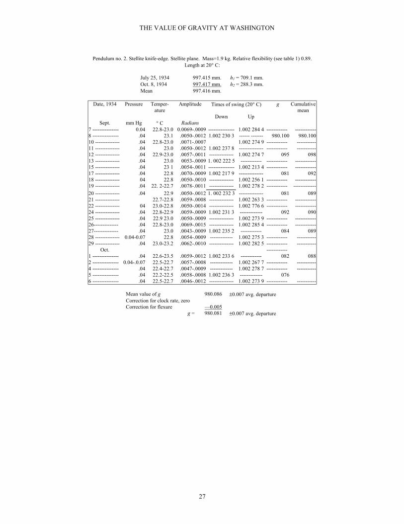
THE VALUE OF GRAVITY AT WASHINGTON
27
Pendulum no. 2. Stellite knife-edge. Stellite plane. Mass=1.9 kg. Relative flexibility (see table 1) 0.89.Length at 20° C:
July 25, 1934 997.415 mm. h1 = 709.1 mm.Oct. 8, 1934 997.417 mm. h2 = 288.3 mm.Mean 997.416 mm.
Date, 1934 Pressure Temper-ature
Amplitude Times of swing (20° C) g Cumulativemean
Down UpSept. mm Hg ° C Radians
7 --------------- 0.04 22.8-23.0 0.0069-.0009 --------------- 1.002 284 4 ------------ ------------8 --------------- .04 23.1 .0050-.0012 1.002 230 3 ------ ------- 980.100 980.10010 -------------- .04 22.8-23.0 .0071-.0007 1.002 274 9 ------------ -----------11 -------------- .04 23.0 .0050-.0012 1.002 237 8 -------------- ------------ -----------12 -------------- .04 22.9-23.0 .0057-.0011 -------------- 1.002 274 7 095 09813 -------------- .04 23.0 0053-.0009 1. 002 222 5 ------------ ------------ ------------15 -------------- .04 23 1 .0054-.0011 --------------- 1.002 213 4 ------------ ------------17 -------------- .04 22.8 .0070-.0009 1.002 217 9 -------------- 081 09218 -------------- 04 22.8 .0050-.0010 -------------- 1.002 256 1 ------------ ------------19 -------------- .04 22. 2-22.7 .0078-.0011 -------------- 1.002 278 2 ------------ -------------
20 -------------- .04 22.9 .0050-.0012 1. 002 232 3 -------------- 081 08921 -------------- 22.7-22.8 .0059-.0008 -------------- 1.002 263 3 ------------ ------------22 -------------- 04 23.0-22.8 .0050-.0014 -------------- 1.002 776 6 ------------ ------------24 -------------- .04 22.8-22.9 .0059-.0009 1.002 231 3 ------------- 092 09025 -------------- .04 22.9 23.0 .0050-.0009 -------------- 1.002 273 9 ------------ ------------26-------------- .04 22.8-23.0 .0069-.0015 -------------- 1.002 285 4 ------------ ------------27-------------- .04 23.0 .0043-.0009 1.002 235 2 ------------ 084 08928 -------------- 0.04-0.07 22.8 .0054-.0009 ------------- 1.002 275 3 ------------ -----------29 -------------- .04 23.0-23.2 .0062-.0010 -------------- 1.002 282 5 ------------ -----------
Oct. ------------1 --------------- .04 22.6-23.5 .0059-.0012 1.002 233 6 ------------ 082 0882 --------------- 0.04-.0.07 22.5-22.7 .0057-.0008 ------------- 1.002 267 7 ------------ -----------4 --------------- .04 22.4-22.7 .0047-.0009 ------------- 1.002 278 7 ------------ -----------5 --------------- .04 22.2-22.5 .0058-.0008 1.002 236 3 ------------- 0766 --------------- .04 22.5-22.7 .0046-.0012 -------------- 1.002 273 9 ------------ -----------
Mean value of g 980.086 ±0.007 avg. departureCorrection for clock rate, zeroCorrection for flexure —0.005
g = 980.081 ±0.007 avg. departure

THE VALUE OF GRAVITY AT WASHINGTON
28
[835]TABLE 10.—Values of g
Pendulum no. 3. Stellite knife-edge. Stellite plane. Mass = 3.6 kg. Relative flexibility (see table 1) 0.61.Length at 20° C:
Oct. 11, 1934 997.760 mm. h1 = 695.3 mm.Nov. 22, 1934 997.759 mm. h2 = 302.5 mm.Adopted value 997.760 mm.
Date, 1934 Pressure Temper-ature
Amplitude Times of swing (20° C) g Cumula-tive
meanDown Up
Oct. mm Hg ° C Radians12 ----------- 0.04 22.5-22.7 0.0063-.0012 -------------- 1.002 671 6 -------------- ----------15 ----------- 0.04-0.40 21.9-22.1 .0048-.0011 1.002 496 7 -------------- 980.110 980.11016 ----------- .04 22.2-22.1 .0050-.0011 -------------- 1.002 665 4 -------------- ----------17 ----------- .04 22.1-22.3 .0062-.0013 --------------- 1.002 671 9 -------------- ----------18 ----------- 0.04-0.20 22.3-22.5 .0047-.0009 1.002 503 1 -------------- 088 09919 ----------- .04 22 0-22.3 .0055-.0011 --------------- 1.002 664 8 -------------- ----------22 ----------- .04 22.2-22.4 .0058-.0012 --------------- 1.002 677 7 -------------- ----------23 ----------- .04 22.3-22.5 .0054-.0010 1.001 506 4 -------------- 081 09025 ----------- 0.04-0.05 22.6-22.7 .0052-.0011 --------------- 1.002 665 6 -------------- ----------26 ----------- .04 22.5-22.7 .0049-.0012 --------------- 1.002 670 9 -------------- ----------27 ----------- .04 22.5-22.8 .0069-.0013 1.002 506 7 -------------- 080 09029 ----------- .04 21.8-22.0 .0060-.0016 -------------- 1.002 672 3 -------------- ----------30 ----------- 0.03-0.04 22.0 .0058-.0007 -------------- 1.002 652 5 -------------- ----------31 ----------- .04 22.0-22.2 .0067-.0014 1.002 503 8 -------------- 056
Nov.1 ------------ .04 22.1-22.2 .0050-.0012 --------------- 1.002 415 6 -------------- ----------2 ------------ .01 22.0-22.1 .0055-.0011 --------------- 1.002 675 4 -------------- ----------5 ------------ .04 22.0-22.1 .0055-.0012 1.002 507 0 -------- ----- 081 0836 ------------ .04 22.0-22.2 .0050-.0011 1.002 670 5 --------------7 ------------ 0.04-0.06 22.0-22.1 .0060-.0010 --------------- 1-002 677 5 -------------- ----------8 ------------ .04 22.1-22.2 .0049-.0009 1.002 502 7 -------------- 098 0859 ------------ .04 22.0-22.2 .0054-.0012 --------------- 1.002 672 0 -------------- ----------12 ----------- .04 21.2-21.8 .0056-.0012 --------------- 1.002 671 9 ----------14 ----------- .04 21.3-21.4 .0056-.0011 1.002 506 4 -------------- 080 08415 ----------- .04 21.0-21.4 .0059-.0011 --------------- 1.002 670 4 -------------- ----------16 ----------- .04 21.2-21.4 .0054-.0011 --------------- 1.002 664 3 -------------- ----------19 ----------- .04 21.4-21.6 .0061-.0011 1.002 502 3 -------------- 067 08220 ----------- .04 21.6-21.9 .0057-.0012 --------------- 1.002 641 4 -------------- ----------
Mean value of g 980.082 ±0.011 avg. departureCorrection for clock rate, zeroCorrection for flexure —0.005
g = 980.077 ±0.011 avg. departure
The results in table 12 are of interest only as an illustration of the inferiority of agate to chrome steel or even tostellite as a knife-edge material. The results of this series are better than those of a number of similar cases that mightbe cited. It will be noted that the results given in tables 11 and 12 were obtained within a month of each other, withthe same pendulum, the only difference being the change from stellite to agate in the knife-edge.

THE VALUE OF GRAVITY AT WASHINGTON
29
[836]TABLE 11.—Values of g
Pendulum no. 4. Stellite knife-edge. Stellite plane. Mass = 3.5 kg. Relative flexibility (see table 13) 0.28.Length at 20° C:
July 28,1933 998.818 mm. h1 = 698.8 mm.Sept. 19, 1933 998.820 mmJan. 22,1934 998.817 mm. h2 = 300.0 mm.June 1, 1934 998.818 mm. .Adopted value 998.818 mm.
Date, 1935 Pressure Temper-ature
Amplitude Times of swing (20° C) g Cumula-tive mean
Down UpMay mm Hg ° C Radians
9 --------------- 0.04 21.9-22.0 0.0040-.0004 -------------- 1.003 137 3 --------- -----------10 ------------- .03 22.0-21.9 .0036-.0004 1.003 055 7 -------------- 980.089 980.08911 ------------- .04 22.4-22.1 .0039-.0004 -------------- 1.003 138 9 097 09412 ------------- 0.03-0.04 21.8-21.9 .0041-.0004 1.003 001 7 -------------- 100 09615 ------------- 0.06-0.03 22.1-22.2 .0043-.0004 -------------- 1.003 133 0 102 09716 ------------- .03 21.9 .0029-.0003 1.002 996 5 -------------- 111 10017 ------------- 0.09-0.04 22.2-22.0 .0046-.0004 -------------- 1.003 129 7 111 10219 ------------- .04 22.2 0032-.3003 1.002 994 7 -------------- 102 10221 ------------- .03 22.0-22.1 .0044-.0003 -------------- 1.003 113 2 083 10022 ------------- .04 22.3 .0042-.0004 1.002 098 4 -------------- 077 09823 ------------- .03 22.1 .0039-.0003 -------------- 1.003 112 7 070 09525 ------------- .03 22.0-22.2 .0038-.0003 1.003 002 5 -------------- 069 09226 ------------- .04 22.4-22.1 .0044-.0004 -------------- 1.003 121 9 --------- -----------
Mean value of g 980.092 ±0.013 avg. departureCorrection for clock rate, zeroCorrection for flexure —0.002
g = 980.090 ±0.013 avg. departure
TABLE 12. —Values of g
Pendulum no. 4. Agate knife-edge Stellite planes. Mass = 3.5 kg. Relative flexibility (see table 1) 0.28.Length at 20°C:
July 28,1933 998.818 mm. h1 = 698.8 mm.Sept, 19, 1933 998.820 mm.Jan. 22,1934 998.817 mm. h2 = 300.0 mm.June 1, 1934 998.818 mm. .Adopted value 998.818 mm.
Date, 1934 Pressure Temper-ature
Amplitude Times of swing (20° C) g Cumulative mean
- Down UpMay mm Hg ° C Radians
29 ---------- 0.03-0.04 22.0-22.1 0.0048-.0003 1.002 913 2 -------------- ---------------- -------------31 ---------- .03-0.04 22.2-22.0 .0047-.0004 -------------- 1.002 913 5 980.078 980.078
June1 ----------- 0.04 22.1 .0039-.0004 1.002 911 5 -------------- .084 0812 ----------- .03-0.04 22.1-22.4 .0042-.0004 -------------- 1.002 918 2 .085 0824 ----------- .03-0.04 22.0-22.5 .0042-.0003 1.002 912 6 -------------- .098 0765 ----------- .04-0.05 22.2-22.5 .0043-.0004 -------------- 1.002 879 6 .?7 0686 ----------- .03-0.04 22.2-22.6 .0045-.0003 1.002 917 2 -------------- .068 0657 ----------- 0.04 22.8-22.7 .0040-.0004 -------------- 1.002 928 58 ----------- .03-0.04 22.2-22.5 .0047-.0004 -------------- 1.002 936 4
.089 068
9 ----------- 0.04 22.8 .0042-.0005 1.002 917 6 -------------- ---------------- -------------11 ---------- .03-0. 04 22.4-22.7 .0034-.0003 -------------- 1.002 946 814 ---------- .05-0.04 23.0-22.8 .0038-.0003 -------------- 1.002 872 0
.070 068
15 ---------- 0.04 22.8 .0041-.0005 1.002 908 7 -------------- ---------------- -------------

THE VALUE OF GRAVITY AT WASHINGTON
30
Mean value of g 980.068 ±0.018 avg. departureCorrection for clock rate, zeroCorrection for flexure —0.002
g = 980.066 ±0.018 avg. departure
[837]TABLE 13.—Summary of values of g
Pendulum number ---------------------------------- 2 3 4Relative flexibility --------------------------------- 0.89 0.61 0.28Stellite plane ---------------------------------------Steel knife-edge ------------------------------------ }980.079 ±0.0045
980.080 ±0.003 980.080 ±0.0014
Fused-silica plane ---------------------------------Steel knife-edge ------------------------------------ }-------------------
------------------- 980.075 ±0.003
Stellite plane ---------------------------------------Stellite knife-edge --------------------------------- }980.081 ±0.007
980. 077 ±0 011 980.090 ±0.013
Stellite plane ---------------------------------------Agate knife-edge ----------------------------------- } 980.066 ±0.018
In connection with table 13 the following points may be noted:1. The values of g obtained with the steel knife-edge (rows 1 and 2, table 13) show the greatest precision, the total
spread of the individual values being 0.022 and the average departure from the mean less than 0.005.2. A change in the material of the plane from stellite to fused silica (the knife-edge remaining the same) makes no
change in the order of precision.3. A change in the material of the knife-edge from steel to stellite (row 3) reduces the precision considerably, the
average departure becoming of the order 0.01 and the spread of the individual values 0.055.4. It will be noticed that in some cases (table 7) there is a tendency to a small but steady decrease in the times of
swing, while the value of g remains fairly constant. This may be due to a slight progressive wear of the knife-edge, the effect nearly cancelling out in the application of eq 1.
The mean of the four best results (rows 1 and 2), weighted inversely as their average departures, is 980.079. If weinclude the three second-best results (row 3) the mean is 980.080 ± 0.00311 But even with the four best results thespread of the individual values is 0.022 and the average departure of a set may be as much as 0.0045, it is our feelingthat
g = 980.08 cm sec-2 ±±±±0.003 average departure
goes as far in accuracy as is reasonably certain.It should be noted that this result involves 70 single determinations of g.The geographical coordinates of the gravity station, determined from information furnished by the U.S. Coast and
Geodetic Survey, are as follows:Latitude--------38°56' 30.143” N.Longitude-----77°03' 56.893” W.Elevation above sea level----------94.75 meters.
It may be of assistance in appraising the precision of the foregoing result to summarize the various minor sourcesof error for which no correction was deemed necessary. These are given in table 14.
11 Our earlier results, obtained with knife-edges of agate and fused silica, are of too poor a grade to be considered for inclusion in the finalresult. Table 12 gives an example of perhaps the most presentable of these results.

THE VALUE OF GRAVITY AT WASHINGTON
31
[838]TABLE 14—Effect of minor sources of error
Source Estimated effect on gPosition of knife-edge on plane ---------------------------- Maximum not known. Minimum less
than 1 part per million.Parallelism of plane ---------------------------------------- 1×10⁻⁸.Equality of T1 and T2 --------------------------------------- <1.2×10⁻⁷.Center of gravity in line of supports ----------------------- 2×10⁻⁸.Departure of knife-edge from level ------------------------ 5×10⁻⁷.Error of standard scale ------------------------------------- ≤1×10⁻⁶.Elastic deformation of pendulum under own weight -----
≤1×10⁻⁶.
Microscope error ------------------------------------------- <1×10⁻⁶.Clock-rate variation ---------------------------------------- <<1×10⁻⁶.Motion of support ------------------------------------------- 5×10⁻⁷.Damping ----------------------------------------------------- 2×10⁻⁹.Compressibility of pendulum ------------------------------ 5×10⁻⁷.
VII. THE POTSDAM DETERMINATION
The value of g in the pendulum room at the National Bureau Standards, as deduced from the direct connectionmade with Potsdam to the pendulum room in 1933 by Lt. Brown of the U. S. Coast Geodetic Survey, is 980.100 Thevalue adopted as the result of absolute measurement, is 980.08. The difference, 2 parts in 100,000 suggests that anexamination of possible causes is desirable. In connection it should be remembered that the various connectionsbetween Washington and Potsdam have differed by as much as 9 parts in a million.
The precision claimed in the Potsdam report is ±0.003. It is noted that this is a least, square probable error, andcorresponds much larger average departure front the mean
The Potsdam results are tabulated and discussed as the length of equivalent simple seconds pendulum, andreduced to the value of g only at the end of the report after all reductions had been made. We shall find it convenient,however, to quote the Potsdam results translated into equivalent values of g at the National Bureau of Standards inWashington, using for this purpose the difference found by Lt. Brown:
Potsdam – Washington = + 1.174.
The Potsdam results fall into two classes, those obtained pendulums carrying two knife-edges and those. given bypendulums provided with two planes. In the first class there are given separate values and in the second class 84. Themaximum, and mean values are given in table 15.
TABLE 15.—Values of g at Washington derived from Potsdam
Twoknife-edges
Twoplanes
Maximum ---------------------------------- 980.180 980.136Mean -------------------------------------- 980.090 980.072Minimum ---------------------------------- 980.008 979.983Total spread ------------------------------- 0.172 0.153Average departure from mean ----------- 0.017 0.026Number of individual results ------------ 108 84
[839] Different methods of classifying and weighting the subgroups of individual observations give mean valuesranging from 980.082 to 980.089.
We may direct attention to the following points of interest in the above table.1. The spread of the separate values is nearly 3 times that (0.055) obtained in the less accurate sets of our work.
The average departure from the mean is also considerably greater than ours.2. The 70 single observations in our work will therefore compare favorably with the greater number of
observations of less precision in the Potsdam report.
THE VALUE OF GRAVITY AT WASHINGTON
32
3. The weighted mean of the Potsdam observations, obtained as above, is in reasonable agreement with ouradopted result.
It remains to be explained how this Potsdam experimental mean was increased to give 980.100 at Washington.It was recognized by the Potsdam observers that knife-edge errors played a large part in absolute-gravity work. A
considerable portion of the Potsdam report is devoted to an attempt to evaluate these errors on the basis of variationsin the results given by the different pendulums employed. As a result of this evaluation the value of g was raised to980.100 (at Washington). This process of correction appears to amount for the most part to an extrapolation of theresults obtained with the different pendulums to that which would correspond to a pendulum of zero mass. Themasses of the pendulums ranged from 2.86 to 6.23 kg, and in the extrapolation referred to the lightest pendulumseems to have had a disproportionate influence. Our results do not indicate a variation with mass, and therefore nosuch adjustment has been made.
WASHINGTON, July 29, 1935.