Embed Size (px)
Citation preview

The “V”--- Falco TT Bike White Paper
September 14, 2013
Contents
I. Introduction
II. Approach
A. The Wind
B. Beyond UCI
C. The Predecessors
D. CFD Analysis
E. Wind Tunnel
III. The V Foil
IV. True Kamm
V. Part-by-Part Breakdown of the Aerodynamic Features
A. Top Tube
B. Seat Cluster
C. Seat Stays
D. Seat Tube
E. Head Tube
F. Down Tube
G. The Bottle ---- Asymmetric Total Integration
H. Chain Stays
I. Brakes
J. Cables
K. Aggregate
VI. Stiffness
VII. Comfort
VIII. Geometry and Adjustability
IX. Comparison against other Beam Bikes
X. Conclusion

I Introduction
At Falco Bike, innovation is our life line. Despite winning consecutive innovation awards at bike shows, we were not content, as no bike maker is complete without a worthy TT bike.1 When we started out on this project, we had only one goal in our mind – to make the fastest TT bike in the world. That’s a pretty tall order for a small company like ours. However, if one can look beyond the multi-million dollar pro team sponsorships and marketing campaigns, the competition is ultimately between the designers, mano-a-mano. That, plus the help of the right technology --- We have teamed up with some of the world’s most respected institutions of higher learning2 to leverage the most advanced facilities and depth of knowledge available to man. After all, this goalwas only fitting, as Falco Peregrinus (or the falcon), is the world’s fastest creature with a top speed of close to 400kph.3
Fig. 1 According to National Geographic, Peregrine Falcons are known to have logged the diving speed of 389 kilometers per hour.
Today, after 1700 hours of R&D and hundreds of CFD runs, we present to you the Falco “V”, a TT bike that is estimated save the rider 25 watts compared to the very few “super bikes”, and approximately 40 watts over a typical TT bike on the market today, and which translates into approximately 75 - 115 seconds saved in a 40km time trial.4 Some other noteworthy facts about the V:
Not bound by UCI rules (coz they only slow you down!) Extensive CFD simulation analysis Shared R&D facility as the military used for designing jet fighters Joint effort from four international universities NACA 6-series based airfoil system similar to those found on F22s and F15s Total integrated hydration system Absence of seat cluster, seat stays and most of the seat tube –YA CAN’T HAVE DRAG WHERE
THERE IS NOTHING! Unrivaled adjustability, comfort and ergonomics
1As used in this document, “TT bike”also covers“tri bike”. 2We have obtained valuable assistance from Nanjing University of Aeronautics and Astronautics, University of Tennessee at Knoxville, China University of Science and Technology and Nanjing University. Very special thanks to Prof. Jian Huang of U. of Tennessee, Dr. Chen Wei of NUAA, Mr. Eric Fang of CUST and Mr. Aru Tan of Nanjing U. for their valuable and tireless contribution to this project. 3See http://en.wikipedia.org/wiki/Peregrine_Falcon 4Estimates of watts saved and seconds saved are necessarily based on a set of assumptions and we have adopted assumptions that we believe are common in real world race situations for reasonably fit cyclists.
II The Approach
The following is a summary of our approach to this project. A. The Wind.
Firstly, in order to build a wind-cheating bike, we had to understand the wind relative to a moving cyclist. Many industry players and members of the press have attempted to determine the weighting of different yaw angles of wind relative to a moving bicycle. For example, the Tour magazine measured at 2-degree intervals from-20 to 20 degrees, which seemingly gave equal weight to each 2-degree point.5VeloNews tested at 5-degree intervals across the range from ‒20 to 20 degrees. Zipp, on the other hand, measures yaw distribution with highest weighting assigned to13 degrees, with the range from 7 to 15 degrees being the most significant bracket.6Trek, interestingly, set Arizona and Hawaii as two key scenarios under which their aerodynamicstudies are based upon, each of which represents a different set of yaw weightings. As there is apparently no consensus on the weighting of yaw angles7, we tried to drill down to the bottom of this question by studying wind speed and yaw in real world race situations –in fact, we studied the wind conditions inover adozensignificant road and Ironman races all over the world by extracting useful information from existing meteorological databases for the relevant locations– a rather tedious task but worthy one. This allowed us to isolate the non-bike-related wind elements as the background for the studies below. After that, we considered the interaction of a moving bicycle relative to the background wind conditions. To yield the most meaningful results, we considered and analyzed the following factors: (i) the directions of the wind relative to the ground; (ii) various directions in which cyclists travel for any given race course and the frequency of any change in
such directions; (iii) the range of speeds for typical cyclists/triathletes from 25mph to 30mph and the weightings thereof,
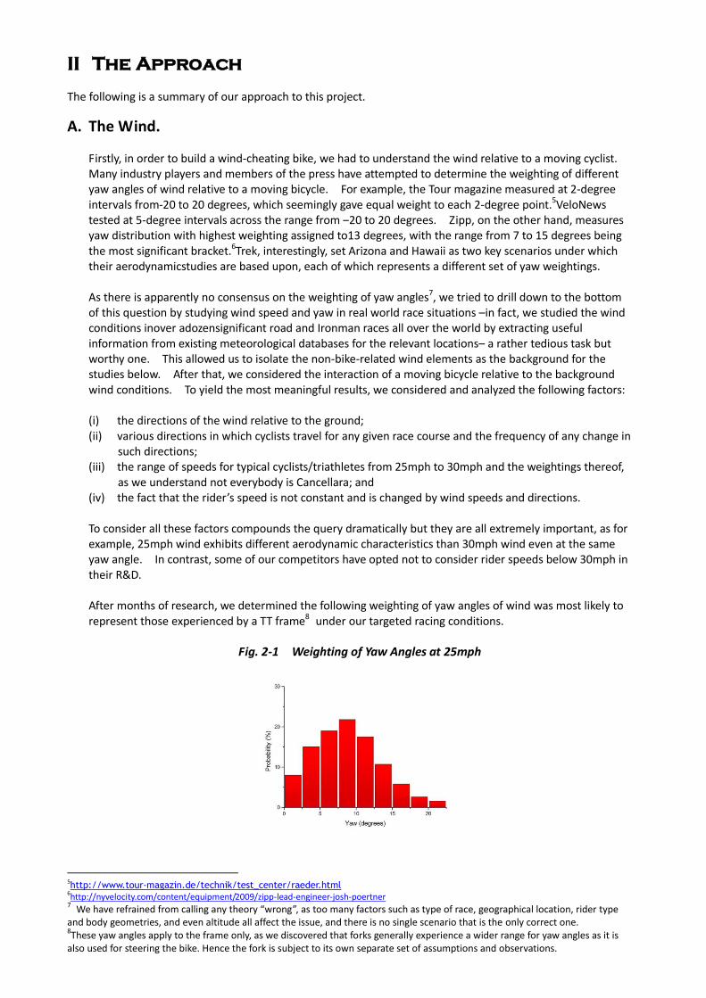
as we understand not everybody is Cancellara; and (iv) the fact that the rider’s speed is not constant and is changed by wind speeds and directions. To consider all these factors compounds the query dramatically but they are all extremely important, as for example, 25mph wind exhibits different aerodynamic characteristics than 30mph wind even at the same yaw angle. In contrast, some of our competitors have opted not to consider rider speeds below 30mph in their R&D. After months of research, we determined the following weighting of yaw angles of wind was most likely to represent those experienced by a TT frame8 under our targeted racing conditions.
Fig. 2-1 Weighting of Yaw Angles at 25mph
5http://www.tour-magazin.de/technik/test_center/raeder.html
6http://nyvelocity.com/content/equipment/2009/zipp-lead-engineer-josh-poertner 7 We have refrained from calling any theory “wrong”, as too many factors such as type of race, geographical location, rider type
and body geometries, and even altitude all affect the issue, and there is no single scenario that is the only correct one. 8These yaw angles apply to the frame only, as we discovered that forks generally experience a wider range for yaw angles as it is
also used for steering the bike. Hence the fork is subject to its own separate set of assumptions and observations.
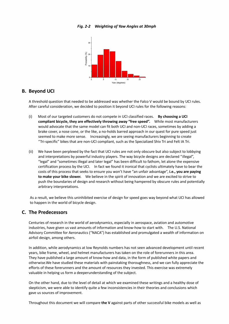
Fig. 2-2 Weighting of Yaw Angles at 30mph
B. Beyond UCI A threshold question that needed to be addressed was whether the Falco V would be bound by UCI rules. After careful consideration, we decided to position it beyond UCI rules for the following reasons: (i) Most of our targeted customers do not compete in UCI classified races. By choosing a UCI
compliant bicycle, they are effectively throwing away “free speed”. While most manufacturers would advocate that the same model can fit both UCI and non-UCI races, sometimes by adding a brake cover, a nose cone, or the like, a no-holds barred approach in our quest for pure speed just seemed to make more sense. Increasingly, we are seeing manufacturers beginning to create “Tri-specific” bikes that are non-UCI compliant, such as the Specialized Shiv Tri and Felt IA Tri.
(ii) We have been perplexed by the fact that UCI rules are not only obscure but also subject to lobbying
and interpretations by powerful industry players. The way bicycle designs are declared “illegal”, “legal” and “sometimes illegal and later legal” has been difficult to fathom, let alone the expensive certification process by the UCI. In fact we found it ironical that cyclists ultimately have to bear the costs of this process that seeks to ensure you won’t have “an unfair advantage”, i.e., you are paying to make your bike slower. We believe in the spirit of innovation and we are excited to strive to push the boundaries of design and research without being hampered by obscure rules and potentially arbitrary interpretations.
As a result, we believe this uninhibited exercise of design for speed goes way beyond what UCI has allowed to happen in the world of bicycle design.
C. The Predecessors
Centuries of research in the world of aerodynamics, especially in aerospace, aviation and automotive industries, have given us vast amounts of information and know-how to start with. The U.S. National Advisory Committee for Aeronautics (“NACA”) has established and promulgated a wealth of information on airfoil design, among others. In addition, while aerodynamics at low Reynolds numbers has not seen advanced development until recent years, bike frame, wheel, and helmet manufacturers has taken on the role of forerunners in this area. They have published a large amount of know-how and data, in the form of published white papers and otherwise.We have studied these materials with painstaking thoroughness, and we can fully appreciate the efforts of these forerunners and the amount of resources they invested. This exercise was extremely valuable in helping us form a deeperunderstanding of the subject. On the other hand, due to the level of detail at which we examined these writings and a healthy dose of skepticism, we were able to identify quite a few inconsistencies in their theories and conclusions which gave us sources of improvement. Throughout this document we will compare the V against parts of other successful bike models as well as
the theories behind them. The goal is not to “discredit” othercommercially successful brands, but to present our understanding of the subject matter and help you make your own informed judgment on what makes a bike faster.
D. CFD Analysis
Computerized Fluid Dynamics (“CFD”) has in recent years become a critical tool in helping bicycle manufacturers refine the aerodynamics of their designs and Falco is no exception. In this respect we were extremely lucky that were we able to team up with Nanjing University of Aeronautics and Astronautics (“NUAA”), which is one of the best institutions of its kind and provider of aerodynamics research for the latest J-31 jet fighter which is one ofthe World’s latest fifth generation jet fighters to rival the F22 and F35.Therefore we had the most powerful and sophisticated CFD facility available to man. In contrast to a leading competitor, we did not run our CFD analysis assuming a wind tunnel environment. Instead, our analysis parameters were purely based on outdoor race conditions as we explained earlier in this document, which was made possible by the complexity of our CFD programming and the capacity of the facility.
E. Wind Tunnel
Wind tunnels are undoubtedly a valuable tool for aerodynamicsresearch. Initially, we planned for wind tunnel testing as part of our exercise. However, based on our discussions with experts at NUAA, we were advised that state-of-the-art CFD programming as those available at NUAA could well replicate wind tunnel testing with an accuracy of well over 99%, and is capable of providing significantly more sophisticated analysis than what can be performed in a wind tunnel. After all, CFD played a much more significant role than the wind tunnel in the aerodynamics research of the J-31 jet fighter. In addition, to the best of our knowledge, every single bike manufacturer that has used both CFD and wind tunnel has stated that wind tunnel results are consistent with their CFD analysis. Therefore, we were finally convinced and made comfortable that wind tunnel testing would not have added additional value to our analysis that was significant enough to warrant the added substantial expenditure, which ultimately would have to be borne by the consumers.
III. The V Foil
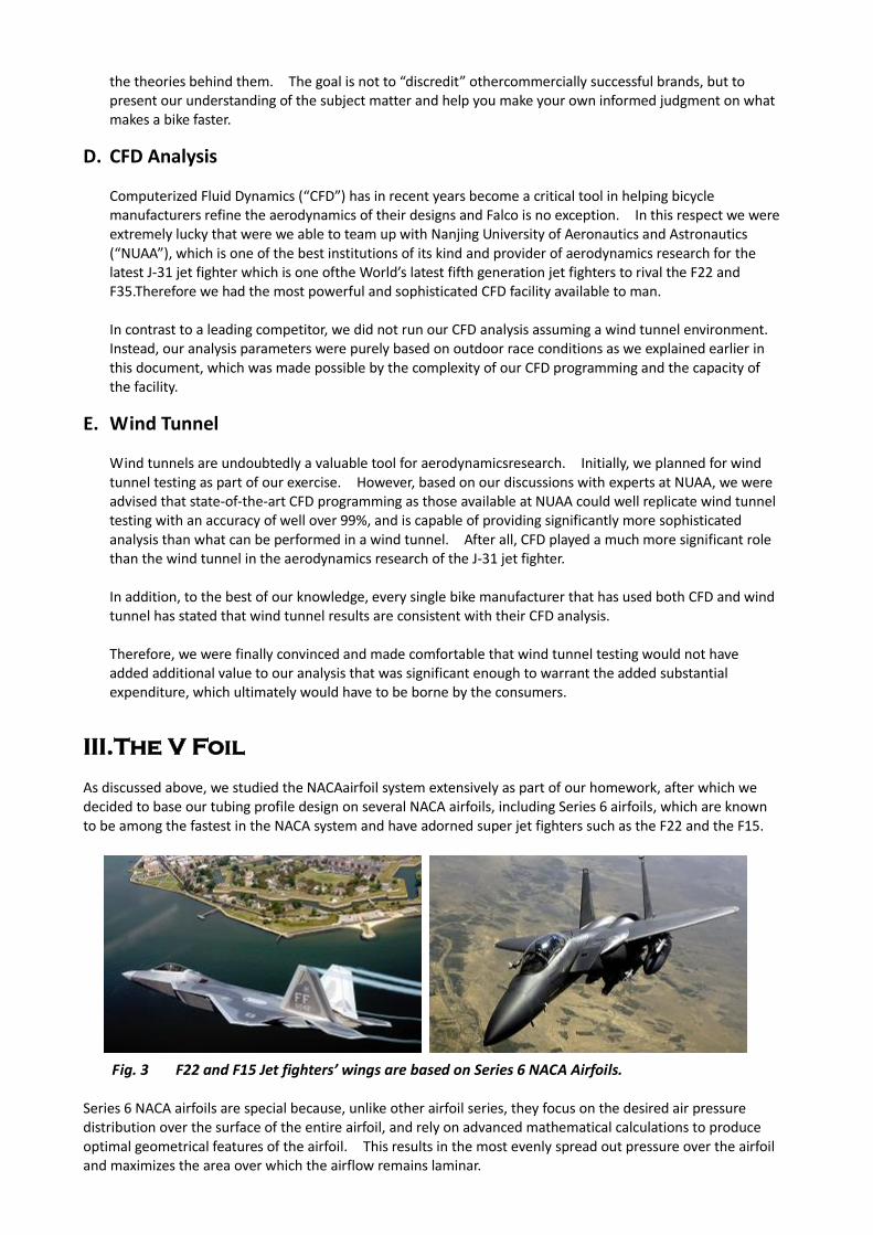
As discussed above, we studied the NACAairfoil system extensively as part of our homework, after which we decided to base our tubing profile design on several NACA airfoils, including Series 6 airfoils, which are known to be among the fastest in the NACA system and have adorned super jet fighters such as the F22 and the F15.
_
Fig. 3 F22 and F15 Jet fighters’ wings are based on Series 6 NACA Airfoils. Series 6 NACA airfoils are special because, unlike other airfoil series, they focus on the desired air pressure distribution over the surface of the entire airfoil, and rely on advanced mathematical calculations to produce optimal geometrical features of the airfoil. This results in the most evenly spread out pressure over the airfoil and maximizes the area over which the airflow remains laminar.
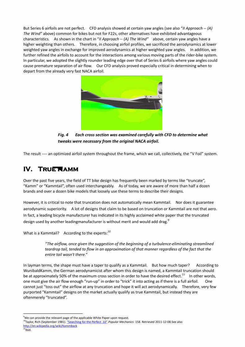
But Series 6 airfoils are not perfect. CFD analysis showed at certain yaw angles (see also “II Approach -- (A) The Wind” above) common for bikes but not for F22s, other alternatives have exhibited advantageous characteristics. As shown in the chart in “II Approach -- (A) The Wind” above, certain yaw angles have a higher weighting than others. Therefore, in choosing airfoil profiles, we sacrificed the aerodynamics at lower weighted yaw angles in exchange for improved aerodynamics at higher weighted yaw angles. In addition, we further refined the airfoils to account for the interactions among various moving parts of the rider-bike system. In particular, we adopted the slightly rounder leading edge over that of Series 6 airfoils where yaw angles could cause premature separation of air flow. Our CFD analysis proved especially critical in determining when to depart from the already very fast NACA airfoil.
Fig. 4 Each cross section was examined carefully with CFD to determine what
tweaks were necessary from the original NACA airfoil.
The result ---- an optimized airfoil system throughout the frame, which we call, collectively, the “V Foil” system. IV. True Kamm
Over the past five years, the field of TT bike design has frequently been marked by terms like “truncate”, “Kamm” or “Kammtail”, often used interchangeably. As of today, we are aware of more than half a dozen brands and over a dozen bike models that loosely use these terms to describe their designs.
However, it is critical to note that truncation does not automatically mean Kammtail. Nor does it guarantee
aerodynamic superiority. A lot of designs that claim to be based on truncation or Kammtail are not that aero.
In fact, a leading bicycle manufacturer has indicated in its highly acclaimed white paper that the truncated
design used by another leadingmanufacturer is without merit and would add drag.9 What is a Kammtail? According to the experts:10
“The airflow, once given the suggestion of the beginning of a turbulence-eliminating streamlined teardrop tail, tended to flow in an approximation of that manner regardless of the fact that the entire tail wasn't there.”
In layman terms, the shape must have a taper to qualify as a Kammtail. But how much taper? According to WunibaldKamm, the German aerodynamicist after whom this design is named, a Kammtail truncation should be at approximately 50% of the maximum cross section in order to have the desired effect.11 In other words, one must give the air flow enough “run-up” in order to “trick” it into acting as if there is a full airfoil. One cannot just “toss out” the airflow at any truncation and hope it will act aerodynamically. Therefore, very few purported “Kammtail” designs on the market actually qualify as true Kammtail, but instead they are oftenmerely “truncated”.
9We can provide the relevant page of the applicable White Paper upon request. 10Taylor, Rich (September 1981). "Searching for the Perfect .10".Popular Mechanics: 158. Retrieved 2011-12-08.See also http://en.wikipedia.org/wiki/Kammback 11Ibid.

Fig. 5 A tube shape that is often used by many as example of a Kammtail,
which is in fact not a Kammtail at all.
In our project, we have indeed adopted Kammtail design in appropriate places, and we have faithfully followed the 50% truncation rule in order to reach the desired aerodynamic effect, which we call “True Kamm”. While the advantage of a Kammtail has long been proven12, two specific examples of the superiority of this design are worth noting in addition to the above: (i) the reduced surface area results in reduced surface frictional drag, and (ii) it has demonstrated improved aerodynamic characteristics at yaw, including even thrust at certain angles13, which has been confirmed by our CFD analysis and also indicated by several other leading bicycle manufacturers.
Fig. 6 Thrust created by the KAMM design at certain yaw angles
V. Part-by-Part Breakdown
of the Aerodynamic Features
A. Top Tube
As we are not bound by UCI rules, we took the liberty of a fully aerodynamic airfoil based on the NACA 64A-010,with minor tweaks to suit the functionality of the bicycle top tube and to account for the interaction among various moving pieces as discussed in III.— The V Foil. CFD analysis has shown encouraging numbers on the top tube.
12 The aerodynamic effect of the Kammtail design was raised and proven in the 1930s. 13 Thrust

Fig. 7 CFD Simulation of the V Foil
We would also like to take this opportunity to clarify a common misconception in aerodynamic bicycle design ---- frontal area. It is a term too often used conveniently (typically along with photos showing narrow tubing profiles) to stand for aerodynamic superiority that may not be there. While frontal area does affect total drag, it is far less relevant than the drag coefficient (“CD”) of the object.14This is because CD values fluctuate much more dramatically than frontal area. For example, the CD value of a brick can be over 20 times more than an optimized airfoil with the same frontal area, so a narrower-but-high CD object can have very high drag. This may not be intuitive but it is proven science.The great Chris Boardman, who is obsessed with aerodynamics, also had expressed his fascination at this fact.15 This is exactly the reason many rim makers are going to the “wide-rim” technology today, i.e. they trade a little bit of frontal area for may better CD.
Fig. 8 Chris Boardman sharing his astonishment on Slowtwitch.com on how
much CD outweighs frontal area in the quest for aero.
In the case of our top tube, it is 50mm at its widest point, yet due to the modified NACA 6-series shape, it in fact is much more aerodynamic than some much narrower top tubes. One example is a “match
14The Drag Equation is as follows:
where FD is the drag force, which is by definition the force component in the direction of the flow velocity,[1]
ρ is the mass density of the fluid, [2] v is the velocity of the object relative to the fluid, A is the reference area, and CD is the drag coefficient. 15See http://forum.slowtwitch.com/gforum.cgi?do=post_view_flat;post=4580110
shaped” top tube from a leadingEuropean bike brand where the top tube shrinks immediately after the head tube and remains fairly narrow. CFD analysis shows this design is not that “aero”as it creates unnecessary vortices at the shrinking points, while sacrificing the stiffness a wider tube could provide.
Fig. 9 Match shaped top tube not being that aero (forget the cables for now) despite the narrow frontal area.
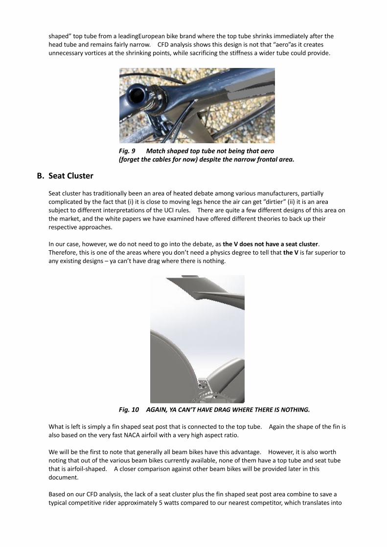
B. Seat Cluster Seat cluster has traditionally been an area of heated debate among various manufacturers, partially complicated by the fact that (i) it is close to moving legs hence the air can get ”dirtier” (ii) it is an area subject to different interpretations of the UCI rules. There are quite a few different designs of this area on the market, and the white papers we have examined have offered different theories to back up their respective approaches. In our case, however, we do not need to go into the debate, as the V does not have a seat cluster. Therefore, this is one of the areas where you don’t need a physics degree to tell that the V is far superior to any existing designs – ya can’t have drag where there is nothing.
Fig. 10 AGAIN, YA CAN’T HAVE DRAG WHERE THERE IS NOTHING. What is left is simply a fin shaped seat post that is connected to the top tube. Again the shape of the fin is also based on the very fast NACA airfoil with a very high aspect ratio. We will be the first to note that generally all beam bikes have this advantage. However, it is also worth noting that out of the various beam bikes currently available, none of them have a top tube and seat tube that is airfoil-shaped. A closer comparison against other beam bikes will be provided later in this document. Based on our CFD analysis, the lack of a seat cluster plus the fin shaped seat post area combine to save a typical competitive rider approximately 5 watts compared to our nearest competitor, which translates into
approximately 16 seconds saved in a 40km time trial.16 C. Seat Stays
Similar to the discussion above, the absence of seat stays on the V helpseliminate turbulences around the moving rear wheel, especially since the top of the rear wheel travels FORWARD at up to two times the speed of the bike.17As our CFD analysis suggested, this feature alone could have the effect of saving a typical competitive rider approximately 3 watts compared to our nearest competitor, which translates into approximately 9seconds saved in a 40km time trial. In addition, we found that this effect is especially pronounced when a rear disc wheel is used, because the laminar boundary layer over the surface of the disc wheel is less likely to be hampered when there are no seat stays in the vicinity.
D. Seat Tube
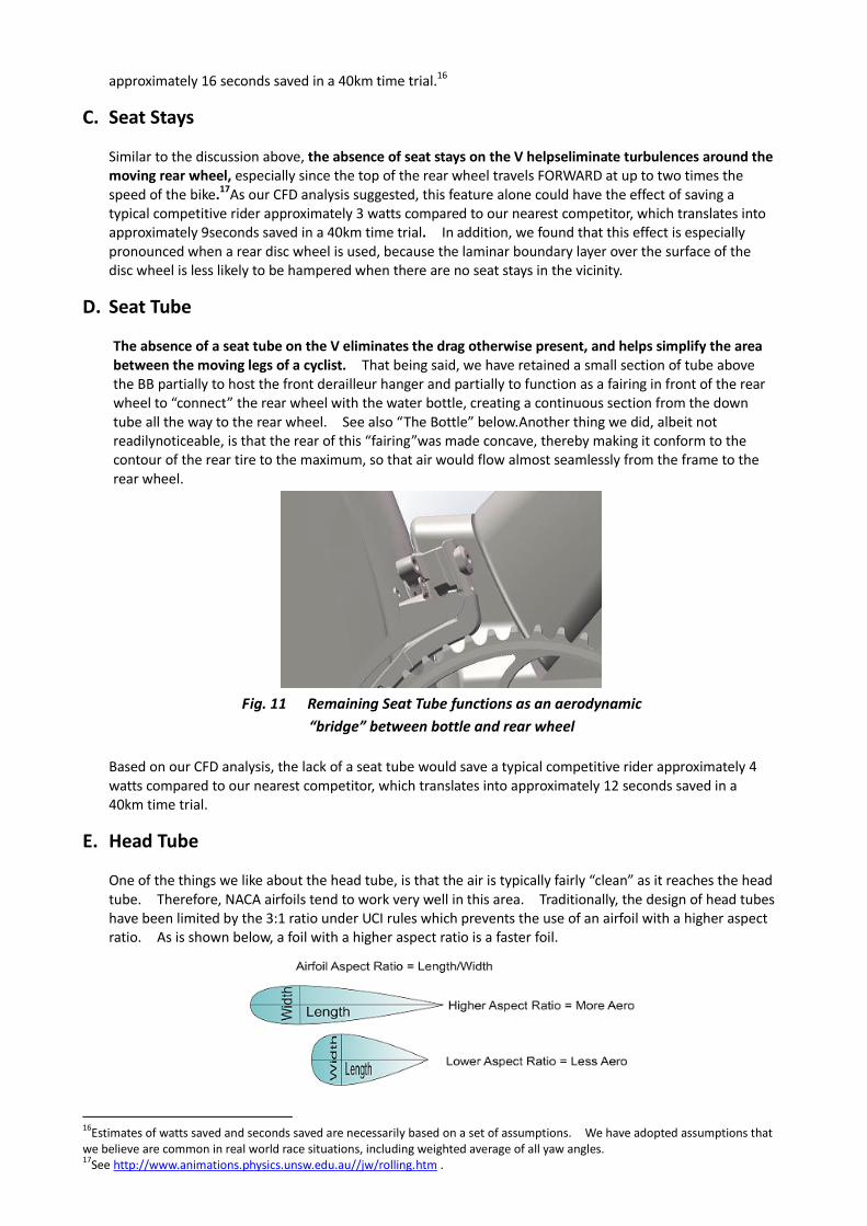
The absence of a seat tube on the V eliminates the drag otherwise present, and helps simplify the area between the moving legs of a cyclist. That being said, we have retained a small section of tube above the BB partially to host the front derailleur hanger and partially to function as a fairing in front of the rear wheel to “connect” the rear wheel with the water bottle, creating a continuous section from the down tube all the way to the rear wheel. See also “The Bottle” below.Another thing we did, albeit not readilynoticeable, is that the rear of this “fairing”was made concave, thereby making it conform to the contour of the rear tire to the maximum, so that air would flow almost seamlessly from the frame to the rear wheel.
Fig. 11 Remaining Seat Tube functions as an aerodynamic
“bridge” between bottle and rear wheel
Based on our CFD analysis, the lack of a seat tube would save a typical competitive rider approximately 4 watts compared to our nearest competitor, which translates into approximately 12 seconds saved in a 40km time trial.
E. Head Tube One of the things we like about the head tube, is that the air is typically fairly “clean” as it reaches the head tube. Therefore, NACA airfoils tend to work very well in this area. Traditionally, the design of head tubes have been limited by the 3:1 ratio under UCI rules which prevents the use of an airfoil with a higher aspect ratio. As is shown below, a foil with a higher aspect ratio is a faster foil.
16
Estimates of watts saved and seconds saved are necessarily based on a set of assumptions. We have adopted assumptions that we believe are common in real world race situations, including weighted average of all yaw angles. 17
See http://www.animations.physics.unsw.edu.au//jw/rolling.htm .
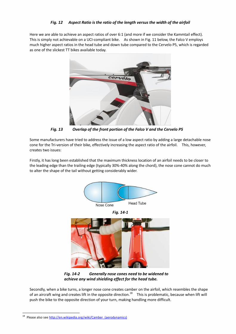
Fig. 12 Aspect Ratio is the ratio of the length versus the width of the airfoil
Here we are able to achieve an aspect ratios of over 6:1 (and more if we consider the Kammtail effect). This is simply not achievable on a UCI-compliant bike. As shown in Fig. 11 below, the Falco V employs much higher aspect ratios in the head tube and down tube compared to the Cervelo P5, which is regarded as one of the slickest TT bikes available today.
Fig. 13 Overlap of the front portion of the Falco V and the Cervelo P5 Some manufacturers have tried to address the issue of a low aspect ratio by adding a large detachable nose cone for the Tri-version of their bike, effectively increasing the aspect ratio of the airfoil. This, however, creates two issues: Firstly, it has long been established that the maximum thickness location of an airfoil needs to be closer to the leading edge than the trailing edge (typically 30%-40% along the chord), the nose cone cannot do much to alter the shape of the tail without getting considerably wider.
Fig. 14-1
Fig. 14-2 Generally nose cones need to be widened to achieve any wind shielding effect for the head tube.
Secondly, when a bike turns, a longer nose cone creates camber on the airfoil, which resembles the shape of an aircraft wing and creates lift in the opposite direction.18 This is problematic, because when lift will push the bike to the opposite direction of your turn, making handling more difficult.
18
Please also see http://en.wikipedia.org/wiki/Camber_(aerodynamics)
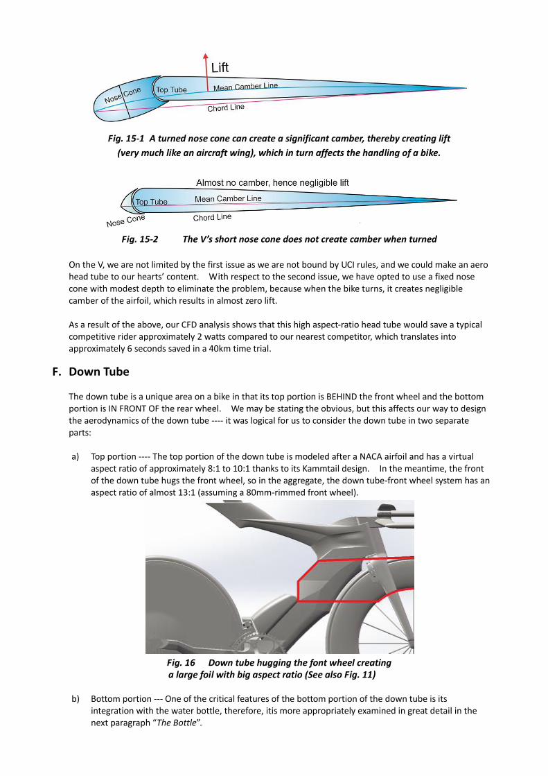
Fig. 15-1 A turned nose cone can create a significant camber, thereby creating lift
(very much like an aircraft wing), which in turn affects the handling of a bike.
Fig. 15-2 The V’s short nose cone does not create camber when turned
On the V, we are not limited by the first issue as we are not bound by UCI rules, and we could make an aero head tube to our hearts’ content. With respect to the second issue, we have opted to use a fixed nose cone with modest depth to eliminate the problem, because when the bike turns, it creates negligible camber of the airfoil, which results in almost zero lift. As a result of the above, our CFD analysis shows that this high aspect-ratio head tube would save a typical competitive rider approximately 2 watts compared to our nearest competitor, which translates into approximately 6 seconds saved in a 40km time trial.
F. Down Tube
The down tube is a unique area on a bike in that its top portion is BEHIND the front wheel and the bottom portion is IN FRONT OF the rear wheel. We may be stating the obvious, but this affects our way to design the aerodynamics of the down tube ---- it was logical for us to consider the down tube in two separate parts: a) Top portion ---- The top portion of the down tube is modeled after a NACA airfoil and has a virtual
aspect ratio of approximately 8:1 to 10:1 thanks to its Kammtail design. In the meantime, the front of the down tube hugs the front wheel, so in the aggregate, the down tube-front wheel system has an aspect ratio of almost 13:1 (assuming a 80mm-rimmed front wheel).
Fig. 16 Down tube hugging the font wheel creating a large foil with big aspect ratio (See also Fig. 11)
b) Bottom portion --- One of the critical features of the bottom portion of the down tube is its
integration with the water bottle, therefore, itis more appropriately examined in great detail in the next paragraph “The Bottle”.
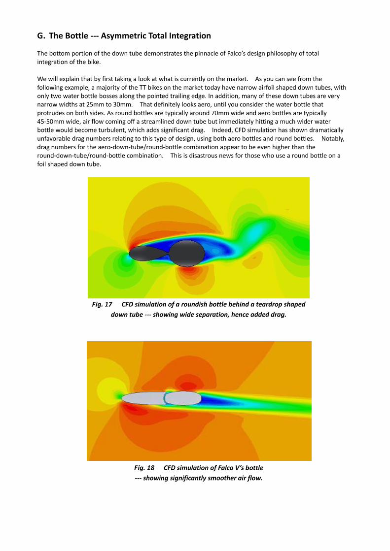
G. The Bottle --- Asymmetric Total Integration The bottom portion of the down tube demonstrates the pinnacle of Falco’s design philosophy of total integration of the bike. We will explain that by first taking a look at what is currently on the market. As you can see from the following example, a majority of the TT bikes on the market today have narrow airfoil shaped down tubes, with only two water bottle bosses along the pointed trailing edge. In addition, many of these down tubes are very narrow widths at 25mm to 30mm. That definitely looks aero, until you consider the water bottle that protrudes on both sides. As round bottles are typically around 70mm wide and aero bottles are typically 45-50mm wide, air flow coming off a streamlined down tube but immediately hitting a much wider water bottle would become turbulent, which adds significant drag. Indeed, CFD simulation has shown dramatically unfavorable drag numbers relating to this type of design, using both aero bottles and round bottles. Notably, drag numbers for the aero-down-tube/round-bottle combination appear to be even higher than the round-down-tube/round-bottle combination. This is disastrous news for those who use a round bottle on a foil shaped down tube.
Fig. 17 CFD simulation of a roundish bottle behind a teardrop shaped
down tube --- showing wide separation, hence added drag.
Fig. 18 CFD simulation of Falco V’s bottle
--- showing significantly smoother air flow.
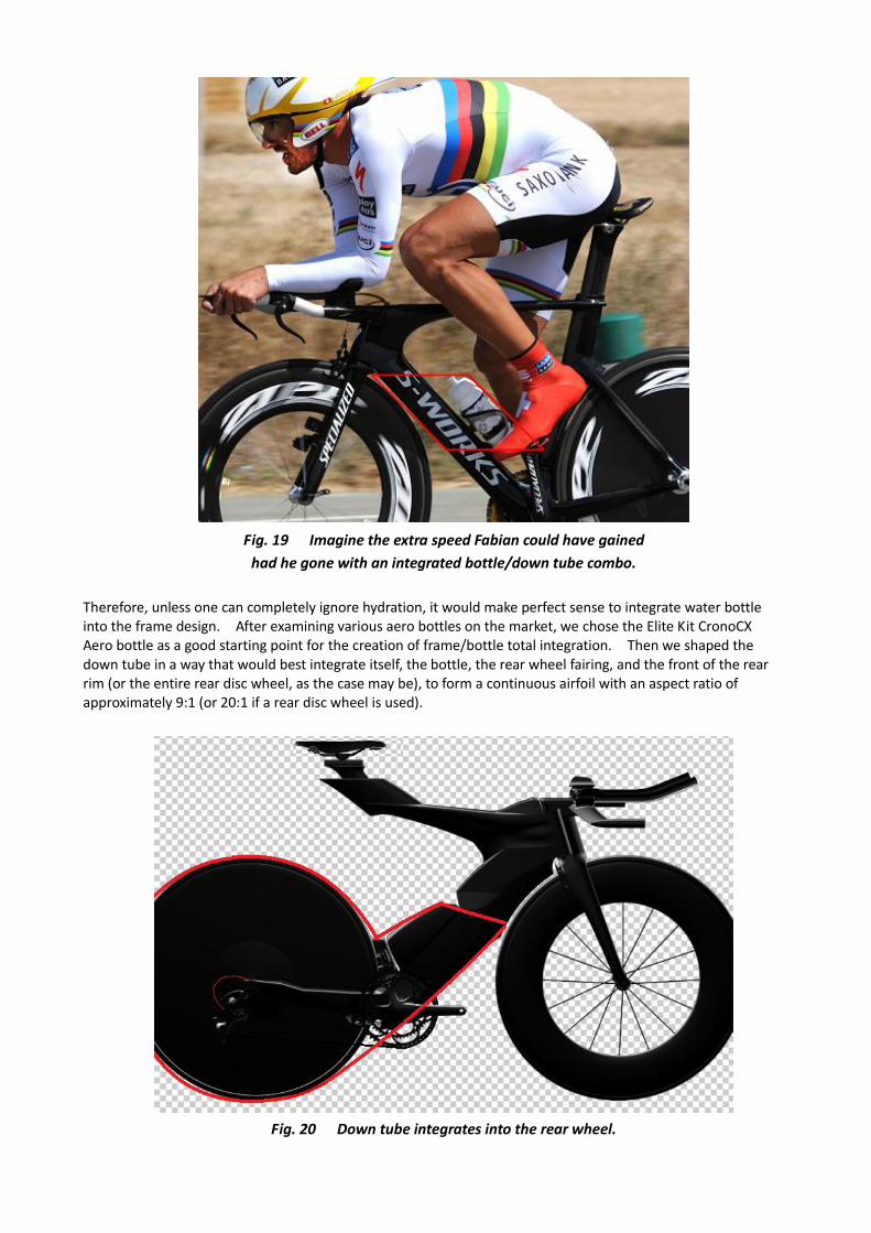
Fig. 19 Imagine the extra speed Fabian could have gained
had he gone with an integrated bottle/down tube combo.
Therefore, unless one can completely ignore hydration, it would make perfect sense to integrate water bottle into the frame design. After examining various aero bottles on the market, we chose the Elite Kit CronoCX Aero bottle as a good starting point for the creation of frame/bottle total integration. Then we shaped the down tube in a way that would best integrate itself, the bottle, the rear wheel fairing, and the front of the rear rim (or the entire rear disc wheel, as the case may be), to form a continuous airfoil with an aspect ratio of approximately 9:1 (or 20:1 if a rear disc wheel is used).
Fig. 20 Down tube integrates into the rear wheel.
In order to improve the integration of the bottle into the down tube, we made a few further refinements to the frame. Firstly, the rear side of down tube would be concave, so that the bottle is effectively “half buried” in the down tube, smoothing the airflow transition from the down tube to the bottle. Since the center of the bottle is dimpled and has mild bulges, making its widest spot at slightly over 50mm, CFD has shown that down tube width closer to the sides of the bottle (i.e, close to 42mm) resulted in most favorable drag numbers. At this point it looked like a promising down tube. However, we wanted to absolutely milk any additional aerodynamic advantage out of this exercise. One thing we noticed was that air flow on the drive side of the frame tends to be considerably “dirtier” than on the non-drive side due to the moving drivetrain. Hence we looked for ways to arbitrage between the two sides. We moved the bottle and the conforming down tube to the right by 10mm making it asymmetric, which yielded the following results: (i) On the non-drive side of the frame, this makes the transition of air flow from the water bottle to the rear
rim smoother; and
(ii) On the drive side of the frame, the slightly protruding bottle creates a partial shield for the front derailleur hanger from on-coming wind, without any material aerodynamic penalty. This is particularly important as little things like a front derailleur can add up quickly to significant drag numbers (see discussion re frontal area in (A) – Top tube).
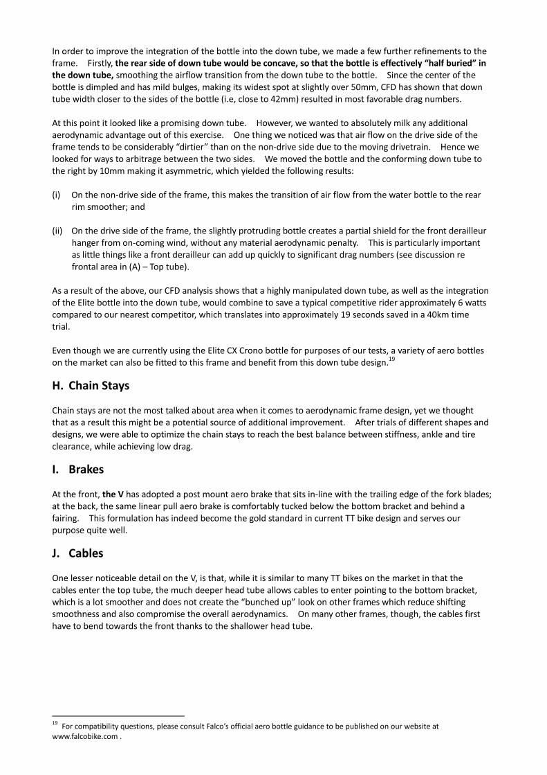
As a result of the above, our CFD analysis shows that a highly manipulated down tube, as well as the integration of the Elite bottle into the down tube, would combine to save a typical competitive rider approximately 6 watts compared to our nearest competitor, which translates into approximately 19 seconds saved in a 40km time trial. Even though we are currently using the Elite CX Crono bottle for purposes of our tests, a variety of aero bottles on the market can also be fitted to this frame and benefit from this down tube design.19 H. Chain Stays Chain stays are not the most talked about area when it comes to aerodynamic frame design, yet we thought that as a result this might be a potential source of additional improvement. After trials of different shapes and designs, we were able to optimize the chain stays to reach the best balance between stiffness, ankle and tire clearance, while achieving low drag. I. Brakes At the front, the V has adopted a post mount aero brake that sits in-line with the trailing edge of the fork blades; at the back, the same linear pull aero brake is comfortably tucked below the bottom bracket and behind a fairing. This formulation has indeed become the gold standard in current TT bike design and serves our purpose quite well. J. Cables One lesser noticeable detail on the V, is that, while it is similar to many TT bikes on the market in that the cables enter the top tube, the much deeper head tube allows cables to enter pointing to the bottom bracket, which is a lot smoother and does not create the “bunched up” look on other frames which reduce shifting smoothness and also compromise the overall aerodynamics. On many other frames, though, the cables first have to bend towards the front thanks to the shallower head tube.
19
For compatibility questions, please consult Falco’s official aero bottle guidance to be published on our website at www.falcobike.com .
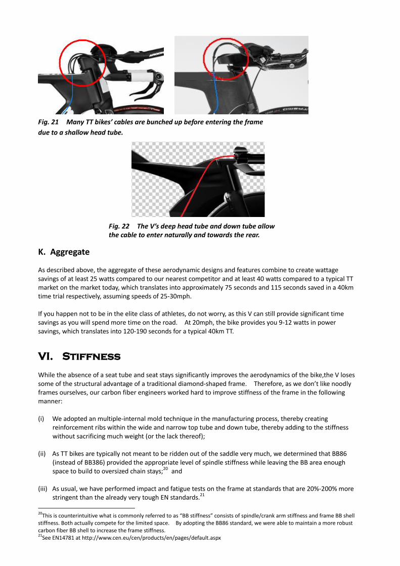
Fig. 21 Many TT bikes’ cables are bunched up before entering the frame
due to a shallow head tube.
Fig. 22 The V’s deep head tube and down tube allow the cable to enter naturally and towards the rear.
K. Aggregate As described above, the aggregate of these aerodynamic designs and features combine to create wattage savings of at least 25 watts compared to our nearest competitor and at least 40 watts compared to a typical TT market on the market today, which translates into approximately 75 seconds and 115 seconds saved in a 40km time trial respectively, assuming speeds of 25-30mph. If you happen not to be in the elite class of athletes, do not worry, as this V can still provide significant time savings as you will spend more time on the road. At 20mph, the bike provides you 9-12 watts in power savings, which translates into 120-190 seconds for a typical 40km TT. VI. Stiffness
While the absence of a seat tube and seat stays significantly improves the aerodynamics of the bike,the V loses some of the structural advantage of a traditional diamond-shaped frame. Therefore, as we don’t like noodly frames ourselves, our carbon fiber engineers worked hard to improve stiffness of the frame in the following manner: (i) We adopted an multiple-internal mold technique in the manufacturing process, thereby creating
reinforcement ribs within the wide and narrow top tube and down tube, thereby adding to the stiffness without sacrificing much weight (or the lack thereof);
(ii) As TT bikes are typically not meant to be ridden out of the saddle very much, we determined that BB86 (instead of BB386) provided the appropriate level of spindle stiffness while leaving the BB area enough space to build to oversized chain stays;20 and
(iii) As usual, we have performed impact and fatigue tests on the frame at standards that are 20%-200% more
stringent than the already very tough EN standards.21
20
This is counterintuitive what is commonly referred to as “BB stiffness” consists of spindle/crank arm stiffness and frame BB shell stiffness. Both actually compete for the limited space. By adopting the BB86 standard, we were able to maintain a more robust carbon fiber BB shell to increase the frame stiffness. 21
See EN14781 at http://www.cen.eu/cen/products/en/pages/default.aspx
VII. Comfort
Time trialing is not meant to be comfortable. It is hard. However, as many of our users will likely be in the saddle for hours at a time, we wanted to make sure this bike is not unduly uncomfortable. The beam design provides a great way of adding comfort, as the beam serves as a suspension device to begin with. In addition, we further fined tuned the carbon layup of the frame to provide more shock absorption in the beam.
VIII. Geometry and adjustability
The V has been calibrated to suit both time trialists and triathletes whose riding positions can be slightly different. Therefore, we have built our “FTF” or “Falco Total Freedom” seat post, which can be easily adjusted and offers a minimum seat tube angle of 75 degree to a maximum of 82 degrees22 which makes it the most accommodating frame on the market in terms of seat angle adjustment. Another feature that may not be easily noticeable is that the FTF seat post slides in a direction that is at an angle to the seat tube angle that allows the taller rider a bit more setback, as our studies have shown that taller riders tend to need more setback due to longer femurs. In contrast many TT bikes on the market have vertical seat tubes that does not allow any extra setback for taller riders. However, experts in tri-bike fitting are increasingly realizing that the “jammed forward” position may not be the most ideal. With respect to adjustment in the front end, we will be offering a set stem or an optional adjustable stem will can tilt up to provide a bit more lower-back-relieving comfort. In addition, while the V maintains unique looks, we have indeed foregone several more striking and futuristic designs in favor of better stand over clearance, more user-friendliness and ample rider ergonomics. Therefore, this is a bike meant to be ridden and not to be hung on a wall. IX. Comparison against other Beam Bikes
The V’s design makes it member of a family of non-UCI legal bikes commonly referred to as “beam bikes”. However, we believe it is revolutionarily more advanced than what traditional beam bikes represent, and we will explain that by comparing the V side-by-side against the hallmark of all beam bikes, the Zipp 2001/300123: (i) Airfoil sections --- the Zipp’s frame tubing cross sections are not exactly airfoils, but rather roundish or
elliptical in most places, while the V has highly calibrated and CFD tested airfoil sections throughout the frame;
(ii) Integration – the Zipp frame does not have any of the aerodynamic/integration features described in
Sections III above; instead, it uses rather traditional road bike parts, including fork, brakes, stem, to name a few, all of which add to the total drag of the bike;
(iii) Adjustment – the Zipp’s seat height adjustment is based on a beam that revolves around a point close to
the head tube, so raising the saddle would also move it forward, as the beam revolves around the pivot, which means less setback for the taller rider. On the V, however, when saddle height is raised, the saddle slides in a direction that provides more setback naturally; and
(iv) Strength – the beam pivot on the Zipp is known to be prone to breakage and loosening issues, while the V
uses a much more conventional seatpost system commonly seen on a number of TT bikes on the market, and hence is not susceptible to such issues.
22
The seat angle measurement may also be depending on seat height. 23
The Zipp 2001 and 3001 frames were designed in the mid-1990s, therefore were excellent engineering work especially for its time, which also inspired us tremendously. That said, we at Falco Bike are honored and humbled to be able to improve upon existing designs and push the advancement even further.

(v) Availability – The Zipp 2001/3001 frames are no longer sold and getting hard to come by.
X. Conclusion
The Falco V represents a milestone of Falco’s quest for innovation and speed. We are also thrilled that we were able to improve upon an exciting bicycle frame structure known as beam bikes and bring it to a new level, offering a technologically advanced ride for the discerning timetrialists and triathletes.