Embed Size (px)
Citation preview

FRITZ GABRIEL BAUERPRESENTS
THE USERS GUIDE TO THESUPER - LIGHTWEIGHT MODULAR
THE ADVANCED MOS MODULAR 35mmMOTION PICTURE CAMERA FOR MULTIPLE
APPLICATIONS AND INCREASED UTILIZATION
Compiled by Frédéric Gérard KaczekIllustrated by Andreas Pauleschitz
WEB-EDITION 2004
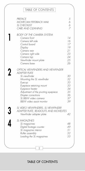
TABLE OF CONTENTSTABLE OF CONTENTS
PREFACE 5MOVIECAM FEEDBACK MAIL 6SL CHECKLIST 6CARE AND CLEANING 7
BODY OF THE CAMERA SYSTEMCamera front 14Camera left side 16Control board 17Display 19Camera rear 21Camera right side 23Camera top 24Viewfinder mount plate 25Camera base 26
OPTICAL VIEWFINDERS AND VIEWFINDER ADAPTER PLATE
SL viewfinder 30Mounting the SL viewfinder 32Eyecup 33Eyepiece retaining mount 33Eyepiece heater 34Adjustment of the pivoting eyepiece 35Diopter corrections 36SL B&W video camera 37B&W video assist monitor 39
SL VIDEO VIEWFINDERS, SL VIEWFINDER ADAPTER PLATE, READOUTS AND MOVIELITES
Viewfinder adapter plate 42
SL MAGAZINESSL magazines 48Digital footage counter 49SL magazine interior 51Roller assembly 52Loading the SL magazines 53
TABLE OF CONTENTS
1
2
34
SL MAGAZINE ADAPTER AND OTHER MAGAZINES
SL magazine adapter 60
CARRYING HANDLE, LIGHTWEIGHT SL BASE AND HANDGRIPS
SL carrying handle 64Right handgrip 65Left handgrip 66SL lightweight base plate 67
INTERIOR OF THE SLInterior of the camera 70Pitch adjustment control 71Ground glasses 72Changing the ground glasses 73Upper aperture plate/gate 75Lower aperture plate 78Pressure plate 80Mirror shutter 81Setting the shutter angle 82
POWER SUPPLIESPower supply unit 86Battery block 88Voltage stabilizer 90
THREADING FILM IN THE SLDoor lock 94Magazine/magazine adapter mounting rail 95Threading film in the SL 96Threading film using the SL magazine adapter 98Dust check knob 107
ACCESSORY BOXES, REMOTE CONTROL AND IRIS CONTROL
Accessory connector 110Accessory box interface 111Remote control 112
56
7
8
10
9
2 3

PREFACETABLE OF CONTENTS
SUPPORT, FOLLOW FOCUS AND MATTE BOXBase plate 11635/S35 base plate 117Lens support 118Studio follow focus 120Lightweight follow focus 123Matte box 125
MISCELLANEOUS AND APPENDIXAssistant work light 130Tools 131Directors finder 132APPENDIXCONNECTORS AND CABLES 136
11
12
The MOVIECAM family has grown - we herewithproudly present our latest ”offspring“, theMOVIECAM SL. This very small camera has a weightof 12,55 lbs / 5,7 kg only incl. magazine forshoulder operation. Contrary to other ”noisy“ cameras,the SL makes, when shooting at 24 or 25 fps, just apleasant, quiet buzzing sound (25 db). Together withthe new body, two new SL MAGAZINES, an SLOPTICAL VIEWFINDER, an SL B&W VIDEO CAMERAand an SL CARRYING HANDLE system have beendeveloped so far. In addition, two new SLADAPTERS and an SL INTERFACE have beendesigned which allow to use several parts from otherMOVIECAM cameras with the SL. For instance, all viewfinder systems of the MOVIECAM COMPACT,incl. several EYEPIECES, READOUTS, VIDEOCAMERAS, VIDEO ASSIST MONITORS andMOVIELITES as well as the MAGAZINES andACCESSORY BOXES can be mounted on the SL.Please take the time to read the following pagescarefully. You will see that this new camera offers youa great variety of possibilities and is at the same timeeasy to handle. For descriptions of all compatibleparts of the MOVIECAM family, please consult theupdated edition ‘95 of the COMPACT USERS GUIDE.For further general or technical information, please feelfree to contact one of our MOVIECAM rental housesor directly the MOVIECAM Headquarters in Vienna,Austria (for addresses and phone numbers, seeappendix). We built this camera for you – now youmay enjoy the MOVIECAM SL!
Gabriel Bauer and Team, Vienna 1995
PREFACE
4 5

CARE AND CLEANINGFEEDBACK CARD
Like the MOVIECAM SL system itself, its users guideconsists of several interchangeable parts that willcontinuously be updated. Just send an E-mail bypushing HERE directly to the Vienna Headquartersand future updates will be mailed to you free ofcharge. You may also use this mail to let us know anycomments (e.g. proposals, or – if really necessary –complaints) you may have . . . . .
MOVIECAM FEEDBACK MAIL
MOVIECAM SL CHECKLIST
The attached checklist (see appendix), which is readyto be photocopied, gives a general overview of allmodular parts of the MOVEICAM SL plus thecompatible parts of the COMPACT system and mightbe of help when placing your order.
6
Like the other MOVIECAM cameras, theMOVIECAM SL is almost maintenance-free. There is only one requirement for a smooth operation: the camera has to be meticulously clean. Thereforeyou should protect it against any dirt or smudges.Clean the camera exterior with window cleaner(caution - do not moisten connectors!). Cleaning themagazine exterior is identical whether it is ofaluminum or carbon fiber. Only when really necessary, e.g. to remove cameratape gum, should you use alcohol or benzine. Caution: Never use acetone!When applied properly, compressed air is the bestcleaner; a vacuum cleaner or an air syringe will dofine.Cotton tips, orangewood sticks, soft and hardbrushes may be used for gentle cleaning.Caution: The camera may be lubricated at aMOVIECAM service center only!
CARE AND CLEANING
7
Warning! Socket and/or pinning might have been changedby some rental houses. Be aware of that whenputting your equipment together.

THE SL SYSTEM THE SL SYSTEM
8 9
[1] [2] [3]
[10] [12]
[13]
[18]
[16] [17][15][6]
[9]
[11]
[7][5] [6] [8][4]
[7] [14]
RAW STOCK
PRESET
SET
ftm
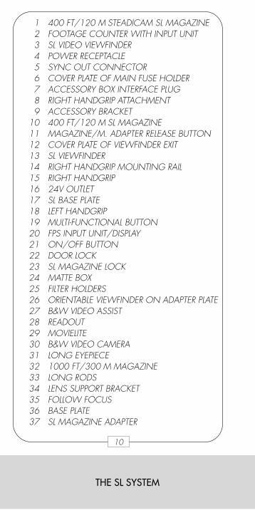
1 400 FT/120 M STEADICAM SL MAGAZINE2 FOOTAGE COUNTER WITH INPUT UNIT3 SL VIDEO VIEWFINDER4 POWER RECEPTACLE5 SYNC OUT CONNECTOR6 COVER PLATE OF MAIN FUSE HOLDER 7 ACCESSORY BOX INTERFACE PLUG8 RIGHT HANDGRIP ATTACHMENT9 ACCESSORY BRACKET
10 400 FT/120 M SL MAGAZINE11 MAGAZINE/M. ADAPTER RELEASE BUTTON12 COVER PLATE OF VIEWFINDER EXIT13 SL VIEWFINDER14 RIGHT HANDGRIP MOUNTING RAIL15 RIGHT HANDGRIP16 24V OUTLET17 SL BASE PLATE18 LEFT HANDGRIP19 MULTI-FUNCTIONAL BUTTON20 FPS INPUT UNIT/DISPLAY21 ON/OFF BUTTON22 DOOR LOCK23 SL MAGAZINE LOCK24 MATTE BOX25 FILTER HOLDERS26 ORIENTABLE VIEWFINDER ON ADAPTER PLATE27 B&W VIDEO ASSIST28 READOUT29 MOVIELITE30 B&W VIDEO CAMERA31 LONG EYEPIECE32 1000 FT/300 M MAGAZINE33 LONG RODS34 LENS SUPPORT BRACKET35 FOLLOW FOCUS36 BASE PLATE37 SL MAGAZINE ADAPTER

THE SL SYSTEM THE SL SYSTEM
8 9
[1] [2] [3]
[10] [12]
[13]
[18]
[16] [17][15][6]
[9]
[11]
[7][5] [6] [8][4]
[7] [14]
RAW STOCK
PRESET
SET
ftm
1 400 FT/120 M STEADICAM SL MAGAZINE2 FOOTAGE COUNTER WITH INPUT UNIT3 SL VIDEO VIEWFINDER4 POWER RECEPTACLE5 SYNC OUT CONNECTOR6 COVER PLATE OF MAIN FUSE HOLDER 7 ACCESSORY BOX INTERFACE PLUG8 RIGHT HANDGRIP ATTACHMENT9 ACCESSORY BRACKET
10 400 FT/120 M SL MAGAZINE11 MAGAZINE/M. ADAPTER RELEASE BUTTON12 COVER PLATE OF VIEWFINDER EXIT13 SL VIEWFINDER14 RIGHT HANDGRIP MOUNTING RAIL15 RIGHT HANDGRIP16 24V OUTLET17 SL BASE PLATE18 LEFT HANDGRIP19 MULTI-FUNCTIONAL BUTTON20 FPS INPUT UNIT/DISPLAY21 ON/OFF BUTTON22 DOOR LOCK23 SL MAGAZINE LOCK24 MATTE BOX25 FILTER HOLDERS26 ORIENTABLE VIEWFINDER ON ADAPTER PLATE27 B&W VIDEO ASSIST28 READOUT29 MOVIELITE30 B&W VIDEO CAMERA31 LONG EYEPIECE32 1000 FT/300 M MAGAZINE33 LONG RODS34 LENS SUPPORT BRACKET35 FOLLOW FOCUS36 BASE PLATE37 SL MAGAZINE ADAPTER
THE SL SYSTEM
10
[23][21] [22] [10][19] [20]
[25] [26][24] [27] [28] [30][29] [31] [32]
[33] [34] [36][35] [37]
[11]
11

THE SL SYSTEM
1 400 FT/120 M STEADICAM SL MAGAZINE2 FOOTAGE COUNTER WITH INPUT UNIT3 SL VIDEO VIEWFINDER4 POWER RECEPTACLE5 SYNC OUT CONNECTOR6 COVER PLATE OF MAIN FUSE HOLDER 7 ACCESSORY BOX INTERFACE PLUG8 RIGHT HANDGRIP ATTACHMENT9 ACCESSORY BRACKET
10 400 FT/120 M SL MAGAZINE11 MAGAZINE/M. ADAPTER RELEASE BUTTON12 COVER PLATE OF VIEWFINDER EXIT13 SL VIEWFINDER14 RIGHT HANDGRIP MOUNTING RAIL15 RIGHT HANDGRIP16 24V OUTLET17 SL BASE PLATE18 LEFT HANDGRIP19 MULTI-FUNCTIONAL BUTTON20 FPS INPUT UNIT/DISPLAY21 ON/OFF BUTTON22 DOOR LOCK23 SL MAGAZINE LOCK24 MATTE BOX25 FILTER HOLDERS26 ORIENTABLE VIEWFINDER ON ADAPTER PLATE27 B&W VIDEO ASSIST28 READOUT29 MOVIELITE30 B&W VIDEO CAMERA31 LONG EYEPIECE32 1000 FT/300 M MAGAZINE33 LONG RODS34 LENS SUPPORT BRACKET35 FOLLOW FOCUS36 BASE PLATE37 SL MAGAZINE ADAPTER
THE SL SYSTEM
10
[23][21] [22] [10][19] [20]
[25] [26][24] [27] [28] [30][29] [31] [32]
[33] [34] [36][35] [37]
[11]
11

CHAPTER 1THE BODY OF
THE COMPACT-SYSTEM
Notes:
12

CHAPTER 1THE BODY OFTHE SL-SYSTEM
Notes:
12

CHAPTER 1THE BODY OF THE SL SYSTEM
The lower connector [1] may be used for the remote controlof the on/off button (e.g. RIGHT HANDGRIP button). Thedovetail type accessory bracket [3] is used to hold theCARRYING HANDLE or the LIGHTWEIGHT FOLLOWFOCUS device.
15
CHAPTER 1THE BODY OF THE SL SYSTEM
Contrary to the other MOVIECAM CAMERAS, theMOVIECAM SL is provided only with an ARRI PL lensmount [5]. Depending on the mounting, you can shooteither STANDARD 35 or SUPER 35 format. This choice hasto be stated at the rental house where the necessarychanges are made. To remove the MOUNT CAP [6] or thelens itself, turn the two bayonet levers [4] counter-clockwise.To mount a lens, turn the levers gently clockwise until thelens is seated properly. Do not use force! Left of the lens mount there are two connectors. The top one[2] has a 24 V outlet, is protected by a 1,6 A multifuse andmay be used for any remote-controlled device, e.g. zoomdrive. In case of an external short circuit, e.g. defectivezoom drive, the automatic multifuse cuts off the powersupply of the connector. To reactivate the multifuse, removethe part that caused the short circuit; disconnect the camerafor approx. 30 seconds, i.e. power supply has to be totallycut.Remark: Depending on the customer´s requests, the cameramay be delivered with different types of connectors. Makesure that all the accessories, cables and plugs you order fittogether.
Fig. 2 – CAMERA FRONT
On/off button outlet
24 V outlet
Accessory bracket(Dovetail)
Lens mount lever
Lens mount
Lens mount cap
Tape measure hook
Accessory/STEADICAMattachment
[1]
[2]
[3]
[4]
[5]
[6]
[10]
[20]
[4] [20]
[10][3]
[2]
[1]
14

CHAPTER 1THE BODY OF THE SL SYSTEM
Power (24 V) for eyecup heater or ASSISTANT WORKLIGHT is supplied via the connector [8].The tape measure is attached to the hook [10] thatindicates the image plane.
[4] - Lens mount lever[7] - On/off button[8] - Connector 24 V / 400 mA[9] - Multi-functional button[10] - Tape measure hook[15] - Cover plate for Viewfinder exit[23] - FPS display[24] - FPS input unit[green LED] - Camera is running[red LED] - Battery low, out of sync
Fig. 3b – CONTROL BOARD
[15][10]
[8]
[24]
[7]
[4]
[23]
[9]
17
[greenLED]
[redLED]
CHAPTER 1THE BODY OF THE SL SYSTEM
[4] - Lens mount lever[7]- On/off button[8] - Connector 24 V / 400 mA[9] - Multi-functional button[10] - Tape measure hook[11] - Magazine / Magazine adapter connector[12] - Door lock[15] - Cover plate for Viewfinder exit[16] - Power receptacle[19] - Magazine / Magazine adapter release button[23] - FPS display[24] - FPS input unit[green LED] -Camera is running[red LED] - Battery low, out of sync
The door is located at the left side of the camerabody. When it is closed, the door lock [12] must beflush with the door. By turning the door lock the door isfirmly pressed onto the camera body so no light canenter.In case of difficulties when closing the door, do not useforce! Please check whether the movement is in its frontposition and the film guides are closed.
Fig. 3a – CAMERA LEFT SIDE
[15] [10] [20] [19]
[11]
[12]
[16]
[7]
[4]
[23]
[9]
16
[green LED]
[red LED]
[24]
[8]

CHAPTER 1THE BODY OF THE SL SYSTEM
Power (24 V) for eyecup heater or ASSISTANT WORKLIGHT is supplied via the connector [8].The tape measure is attached to the hook [10] thatindicates the image plane.The multi-functional button [9] has the following threefunctions:
[4] - Lens mount lever[7] - On/off button[8] - Connector 24 V / 400 mA[9] - Multi-functional button[10] - Tape measure hook[15] - Cover plate for Viewfinder exit[23] - FPS display[24] - FPS input unit[green LED] - Camera is running[red LED] - Battery low, out of sync
Fig. 3b – CONTROL BOARD
[15][10]
[8]
[24]
[7]
[4]
[23]
[9]
17
[greenLED]
[redLED]
CHAPTER 1THE BODY OF THE SL SYSTEM
[4] - Lens mount lever[7]- On/off button[8] - Connector 24 V / 400 mA[9] - Multi-functional button[10] - Tape measure hook[11] - Magazine / Magazine adapter connector[12] - Door lock[15] - Cover plate for Viewfinder exit[16] - Power receptacle[19] - Magazine / Magazine adapter release button[23] - FPS display[24] - FPS input unit[green LED] -Camera is running[red LED] - Battery low, out of sync
The door is located at the left side of the camerabody. When it is closed, the door lock [12] must beflush with the door. By turning the door lock the door isfirmly pressed onto the camera body so no light canenter.In case of difficulties when closing the door, do not useforce! Please check whether the movement is in its frontposition and the film guides are closed.
Fig. 3a – CAMERA LEFT SIDE
[15] [10] [20] [19]
[11]
[12]
[16]
[7]
[4]
[23]
[9]
16
[green LED]
[red LED]
[24]
[8]
CHAPTER 1THE BODY OF THE SL SYSTEM
Flashing when a buckle switch hasbeen interrupted (e.g. badlythreaded film).
Stand-by camera.
Lighting when camera runs with 12 fps.Flashing when lower speed hasbeen selected.
Lighting when camera runs with 24 fps.
Lighting when camera runs with 32 fps.Flashing when a higher speed hasbeen selected.
Flashing when multi-functional knobis pressed and mirror shutter is inshooting position.
Shows malfunction of the drivingsystem (motor, electronics).
Following information is provided by the display onthe control board of the MOVIECAM SL, on theREADOUT or on the REMOTE CONTROL BOX
– MOVIECAM SL without ACCESSORY BOX:
19
Fig. 3c – DISPLAY
CHAPTER 1THE BODY OF THE SL SYSTEM
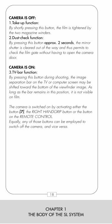
CAMERA IS OFF:1.Take-up function:By shortly pressing this button, the film is tightened bythe two magazine winders.2.Dust-check function:By pressing this button approx. 2 seconds, the mirrorshutter is cleared out of the way and thus permits tocheck the film gate without having to open the cameradoor.
CAMERA IS ON:3.TV-bar function:By pressing this button during shooting, the imageseparation bar on the TV or computer screen may beshifted toward the bottom of the viewfinder image. Aslong as the bar remains in this position, it is not visibleon film.
The camera is switched on by activating either thebutton [7], the RIGHT HANDGRIP button or the buttonon the REMOTE CONTROL.Equally, any of those buttons can be employed toswitch off the camera, and vice versa.
18

CHAPTER 1THE BODY OF THE SL SYSTEM
Flashing when a buckle switch hasbeen interrupted (e.g. badlythreaded film).
Stand-by camera.
Lighting when camera runs with 12 fps.Flashing when lower speed hasbeen selected.
Lighting when camera runs with 24 fps.
Lighting when camera runs with 32 fps.Flashing when a higher speed hasbeen selected.
Flashing when multi-functional knobis pressed and mirror shutter is inshooting position.
Shows malfunction of the drivingsystem (motor, electronics).
Following information is provided by the display onthe control board of the MOVIECAM SL, on theREADOUT or on the REMOTE CONTROL BOX
– MOVIECAM SL without ACCESSORY BOX:
19
Fig. 3c – DISPLAY
CHAPTER 1THE BODY OF THE SL SYSTEM
The multi-functional button [9] has the following three functions:
CAMERA IS OFF:1.Take-up function:By shortly pressing this button, the film is tightened bythe two magazine winders.2.Dust-check function:By pressing this button approx. 2 seconds, the mirrorshutter is cleared out of the way and thus permits tocheck the film gate without having to open the cameradoor.
CAMERA IS ON:3.TV-bar function:By pressing this button during shooting, the imageseparation bar on the TV or computer screen may beshifted toward the bottom of the viewfinder image. Aslong as the bar remains in this position, it is not visibleon film.
The camera is switched on by activating either thebutton [7], the RIGHT HANDGRIP button or the buttonon the REMOTE CONTROL.Equally, any of those buttons can be employed toswitch off the camera, and vice versa.
18
CHAPTER 1THE BODY OF THE SL SYSTEM
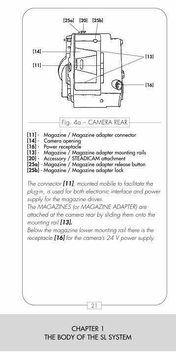
[11] - Magazine / Magazine adapter connector[14] - Camera opening[16] - Power receptacle[13] - Magazine / Magazine adapter mounting rails[20] - Accessory / STEADICAM attachment[25a] - Magazine / Magazine adapter release button[25b] - Magazine / Magazine adapter lock
The connector [11], mounted mobile to facilitate theplug-in, is used for both electronic interface and powersupply for the magazine drives.The MAGAZINES (or MAGAZINE ADAPTER) areattached at the camera rear by sliding them onto themounting rail [13].Below the magazine lower mounting rail there is thereceptacle [16] for the camera’s 24 V power supply.
Fig. 4a – CAMERA REAR
[14]
[16]
[11]
21
[13]
[25a] [20] [25b]
CHAPTER 1THE BODY OF THE SL SYSTEM
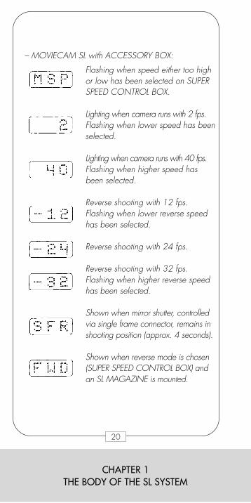
Flashing when speed either too highor low has been selected on SUPERSPEED CONTROL BOX.
Lighting when camera runs with 2 fps.Flashing when lower speed has beenselected.
Lighting when camera runs with 40 fps.Flashing when higher speed hasbeen selected.
Reverse shooting with 12 fps.Flashing when lower reverse speedhas been selected.
Reverse shooting with 24 fps.
Reverse shooting with 32 fps.Flashing when higher reverse speedhas been selected.
Shown when mirror shutter, controlledvia single frame connector, remains inshooting position (approx. 4 seconds).
Shown when reverse mode is chosen(SUPER SPEED CONTROL BOX) andan SL MAGAZINE is mounted.
20
– MOVIECAM SL with ACCESSORY BOX:
CHAPTER 1THE BODY OF THE SL SYSTEM
[11] - Magazine / Magazine adapter connector[14] - Camera opening[16] - Power receptacle[13] - Magazine / Magazine adapter mounting rails[20] - Accessory / STEADICAM attachment[25a] - Magazine / Magazine adapter release button[25b] - Magazine / Magazine adapter lock
The connector [11], mounted mobile to facilitate theplug-in, is used for both electronic interface and powersupply for the magazine drives.The MAGAZINES (or MAGAZINE ADAPTER) areattached at the camera rear by sliding them onto themounting rail [13].Below the magazine lower mounting rail there is thereceptacle [16] for the camera’s 24 V power supply.
Fig. 4a – CAMERA REAR
[14]
[16]
[11]
21
[13]
[25a] [20] [25b]
CHAPTER 1THE BODY OF THE SL SYSTEM
Flashing when speed either too highor low has been selected on SUPERSPEED CONTROL BOX.
Lighting when camera runs with 2 fps.Flashing when lower speed has beenselected.
Lighting when camera runs with 40 fps.Flashing when higher speed hasbeen selected.
Reverse shooting with 12 fps.Flashing when lower reverse speedhas been selected.
Reverse shooting with 24 fps.
Reverse shooting with 32 fps.Flashing when higher reverse speedhas been selected.
Shown when mirror shutter, controlledvia single frame connector, remains inshooting position (approx. 4 seconds).
Shown when reverse mode is chosen(SUPER SPEED CONTROL BOX) andan SL MAGAZINE is mounted.
20
– MOVIECAM SL with ACCESSORY BOX:

CHAPTER 1THE BODY OF THE SL SYSTEM
[1] - On/off button outlet[2] - 24 V outlet[3] - Accessory bracket (Dovetail)[4] - Lens mount lever[6] - Lens mount cap[10] - Tape measure hook[15] - Cover plate for VIEWFINDER exit[16] - Power receptacle[17] - Cover plate of the main fuse holder[18] - Accessory bracket[18 ] - Cover plate for accessory box interface plug[20] - Accessory/STEADICAM attachment[21] - Threaded socket and gauged boreholes for
CARRYING HANDLE attachment[22] - Accessory bracket / RIGHT HANDGRIP attachment[25a] - Magazine /Magazine adapter release button[26] - Sync out connector
The CARRYING HANDLE is attached to the threadedsocket and gauged boreholes [21] on top of thecamera right side; the RIGHT HANDGRIP attachmentplate is slid onto the rail [22]. Below the cover plate[18] there is the interface plug for the accessory boxes.The main fuse of the camera (Glass fuse: 6,3 A slow, 5x 20 mm) is located below the cover plate [17].
Fig. 5 – CAMERA RIGHT SIDE
[25a] [21] [20] [10] [15]
23
[26][16]
[17]
[18]
[4]
[3][6]
[2]
[1][22]
CHAPTER 1THE BODY OF THE SL SYSTEM
On top of the camera rear, there is a small unlockingbutton [25a]. When mounting the SL MAGAZINE orthe SL MAGAZINE ADAPTER to the camera, you willhear a click which indicates that the lock [25b] itself is engaged in the MAGAZINE/MAGAZINE ADAPTERnotch and the MAGAZINE/MAGAZINE ADAPTER isfirmly mounted. By pressing the small unlocking button[25a], the lock shifts upwards and the MAGAZINE/MAGAZINE ADAPTER can be removed by pulling itgently outward.
22
Fig. 4b – MAGAZINE/M.ADAPTER LOCK
[20] [25a] [25b]

CHAPTER 1THE BODY OF THE SL SYSTEM
The viewfinder systems are attached to the gaugedborehole and threaded sockets [30] and flanged to theplate [29] on top of the glass surface.
Caution: Do n o t touch the adjusting and retainingscrews [0] - they are reserved for the technicians ofthe rental house only!
Fig. 6b – VIEWFINDER MOUNT PLATE
25
[30][29]
[30]
[0][0]
[0]
CHAPTER 1THE BODY OF THE SL SYSTEM
[10] - Tape measure hook[16] - Power receptacle[20] - Accessory / STEADICAM attachment[25a] - Magazine / Magazine adapter release button[27] - Assistant work light bracket[29] - Engraved viewfinder mounting plate[30] - Viewfinder attachment
(gauged borehole/threaded sockets)[0] - Retaining screws
The plate on top of the camera body shows the formatthe camera has been adjusted to (either STANDARD 35or SUPER 35 format).The engraved viewfinder mounting plate [29] is turnedupside down when changing the format at a rentalhouse.
Fig. 6a – CAMERA TOP
24
[16]
[30]
[10]
[29]
[0]
[25a]
[20]
[10][30]
[27]
[0]

CHAPTER 1THE BODY OF THE SL SYSTEM
The viewfinder systems are attached to the gaugedborehole and threaded sockets [30] and flanged to theplate [29] on top of the glass surface.
Caution: Do n o t touch the adjusting and retainingscrews [0] - they are reserved for the technicians ofthe rental house only!
Fig. 6b – VIEWFINDER MOUNT PLATE
25
[30][29]
[30]
[0][0]
[0]
CHAPTER 1THE BODY OF THE SL SYSTEM
[10] - Tape measure hook[16] - Power receptacle[20] - Accessory / STEADICAM attachment[25a] - Magazine / Magazine adapter release button[27] - Assistant work light bracket[29] - Engraved viewfinder mounting plate[30] - Viewfinder attachment
(gauged borehole/threaded sockets)[0] - Retaining screws
The plate on top of the camera body shows the formatthe camera has been adjusted to (either STANDARD 35or SUPER 35 format).The engraved viewfinder mounting plate [29] is turnedupside down when changing the format at a rentalhouse.
Fig. 6a – CAMERA TOP
24
[16]
[30]
[10]
[29]
[0]
[25a]
[20]
[10][30]
[27]
[0]

Notes:
CHAPTER 1THE BODY OF THE SL SYSTEM
27
CHAPTER 1THE BODY OF THE SL SYSTEM
[28]
[A] - ARRI axis[28] - Threaded sockets[0] - Adjusting screws
Contrary to the other MOVIECAM CAMERAS, theSL has only an ARRI - type axis base.
Caution:When working with several camera types, careshould be taken that the accessories, e.g. BASEPLATE, MATTE BOX or FOLLOW FOCUS, can beadjusted to the ARRI axis.Do n o t touch the adjusting screws [0] - they arereserved for the technicians of the rental house only!
Fig. 7 – CAMERA BASE
[0]
26
[A]
CHAPTER 2THE SL OPTICAL- AND THE VIDEO VIEWFINDER
CHAPTER 2SL OPTICAL- AND
VIDEO VIEWFINDER

CHAPTER 2THE SL OPTICAL- AND THE VIDEO VIEWFINDER
CHAPTER 2SL OPTICAL- AND
VIDEO VIEWFINDER

CHAPTER 2THE SL OPTICAL- AND THE VIDEO VIEWFINDER
C) By means of the SL ADAPTER PLATE all OPTICAL and VIDEO VIEWFINDERS of the MOVIECAM COMPTACT system may be used withthe MOVIECAM SL including VIDEO CAMERASand VIDEO ASSIST MONITOR, MOVIELITE,REMOTE CONTROL and READOUT systems.
31
CHAPTER 2THE SL OPTICAL- AND THE VIDEO VIEWFINDER
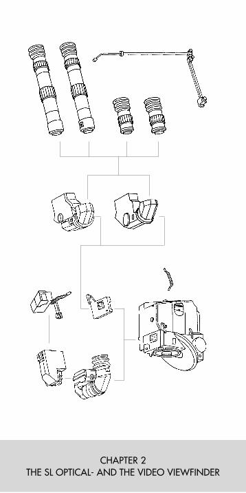
Fig. 8 – THE VIEWFINDERS
30
Various viewfinders may be used with theMOVIECAM SL modular system:A) SL OPTICAL VIEWFINDERB) SL VIDEO VIEWFINDER (B&W VIDEO CAMERA)C) All other OPTICAL and VIDEO VIEWFINDERS
of the COMPACT SYSTEM
A) The SL OPTICAL VIEWFINDER is a lightweight construction with integrated beam splitter.The eyepiece is not interchangeable. It can be rotated 360° only vertically while maintaining an erect image.
B) The SL OPTICAL VIEWFINDER permits the use of the SL VIDEO B&W VIDEO CAMERA (mounted on the top). The light transmission ratio of the built-in beam splitter is 80% / 20% (80% light transmission for the eyepiece, 20% for the video camera).

CHAPTER 2THE SL OPTICAL- AND THE VIDEO VIEWFINDER
C) By means of the SL ADAPTER PLATE all OPTICAL and VIDEO VIEWFINDERS of the MOVIECAM COMPTACT system may be used withthe MOVIECAM SL including VIDEO CAMERASand VIDEO ASSIST MONITOR, MOVIELITE,REMOTE CONTROL and READOUT systems.
31
CHAPTER 2THE SL OPTICAL- AND THE VIDEO VIEWFINDER
Fig. 8 – THE VIEWFINDERS
30
Various viewfinders may be used with theMOVIECAM SL modular system:A) SL OPTICAL VIEWFINDERB) SL VIDEO VIEWFINDER (B&W VIDEO CAMERA)C) All other OPTICAL and VIDEO VIEWFINDERS
of the COMPACT SYSTEM
A) The SL OPTICAL VIEWFINDER is a lightweight construction with integrated beam splitter.The eyepiece is not interchangeable. It can be rotated 360° only vertically while maintaining an erect image.
B) The SL OPTICAL VIEWFINDER permits the use of the SL VIDEO B&W VIDEO CAMERA (mounted on the top). The light transmission ratio of the built-in beam splitter is 80% / 20% (80% light transmission for the eyepiece, 20% for the video camera).

CHAPTER 2THE SL OPTICAL- AND THE VIDEO VIEWFINDER
The eyepiece has an interchangeable RUBBER EYECUP[A]. To clean the exit pupil [B], remove the EYECUP bysimply pulling it straight out.Eye-friendly covers, such as chamois or cotton cloth,can be easily attached with a rubber band. Anotheruseful cover are the terry cloth ”wrist bands“, well-known from tennis, as they are sweat-absorbing,reusable and easy to attach.
Below the RUBBER EYECUP there is a magnetically heldATTACHMENT RING for a diopter correction lens orsome special filter.Lens or filter must have a diameter of 31,5 mm.
Fig. 10 – EYECUP
Fig. 11 – EYECUP RETAINING MOUNT
33
[B]
[A]
CHAPTER 2THE SL OPTICAL- AND THE VIDEO VIEWFINDER
[30] - Threaded sockets[31] - Glass surfaces[32] - Gauged borehole
After removing both caps, the SL OPTICAL VIEWFINDER is mounted to the camera body with threeM5 Allen screws.
Care should be taken that:1. the VIEWFINDER sits plane on the mount,2. the pin engage easily in the gauged borehole and3. both glass surfaces are absolutely clean.
Fig. 9 – MOUNTING THE SL VIEWFINDER
32
[32][30]
[31]

CHAPTER 2THE SL OPTICAL- AND THE VIDEO VIEWFINDER
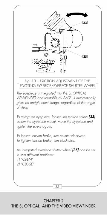
The eyepiece is integrated into the SL OPTICALVIEWFINDER and rotatable by 360°. It automaticallygives an upright erect image, regardless of the angleof view.
To swing the eyepiece, loosen the tension screw [33]below the eyepiece mount, move the eyepiece andtighten the screw again.
To loosen tension brake, turn counter-clockwise.To tighten tension brake, turn clockwise.
An integrated eyepiece shutter wheel [35] can be setto two different positions:1) ”OPEN“2) ”CLOSE“
Fig. 13 – FRICTION ADJUSTMENT OF THEPIVOTING EYEPIECE/EYEPIECE SHUTTER WHEEL
35
[35]
[33]
CHAPTER 2THE SL OPTICAL- AND THE VIDEO VIEWFINDER
A heated eyecup, which eliminates fogging of the exit pupil, is integrated in the eyepiece of theMOVIECAM SL.There is no on/off switch for the eyecup heater; inorder to activate it, disconnect the camera, plug oneend of the short coiled cable into the eyepiececonnector, the other end into one of the connectors [8].Connectors on camera and eyepiece are identical.
Fig. 12 – EYECUP HEATER
[8]
34
[8]
CHAPTER 2THE SL OPTICAL- AND THE VIDEO VIEWFINDER
An SL B&W VIDEO CAMERA can be attached to theSL OPTICAL VIEWFINDER.
At the top side of the SL OPTICAL VIEWFINDER,below a cover [15], there is the exit pupil for the videoimage and a small connector for the power supply ofthe VIDEO CAMERA. Always attach the cover to theOPTICAL VIEWFINDER (with two M5 Allen screws)when no VIDEO CAMERA is installed.
The VIDEO CAMERA has a similar cover.
Fig. 15a +15b – SL B&W VIDEO CAMERA
37
[15]
CHAPTER 2THE SL OPTICAL- AND THE VIDEO VIEWFINDER
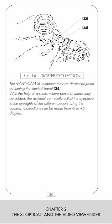
The MOVIECAM SL eyepiece may be diopter-adjustedby turning the knurled barrel [34].With the help of a scale, where personal marks maybe added, the assistant can easily adjust the eyepieceto the eyesights of the different people using thecamera. Corrections can be made from -5 to +5diopters.
Fig. 14 – DIOPTER CORRECTION
36
[33]
[34]

CHAPTER 2THE SL OPTICAL- AND THE VIDEO VIEWFINDER
An SL B&W VIDEO CAMERA can be attached to theSL OPTICAL VIEWFINDER.
At the top side of the SL OPTICAL VIEWFINDER,below a cover [15], there is the exit pupil for the videoimage and a small connector for the power supply ofthe VIDEO CAMERA. Always attach the cover to theOPTICAL VIEWFINDER (with two M5 Allen screws)when no VIDEO CAMERA is installed.
The VIDEO CAMERA has a similar cover.
Fig. 15a +15b – SL B&W VIDEO CAMERA
37
[15]
CHAPTER 2THE SL OPTICAL- AND THE VIDEO VIEWFINDER
The MOVIECAM SL eyepiece may be diopter-adjustedby turning the knurled barrel [34].With the help of a scale, where personal marks maybe added, the assistant can easily adjust the eyepieceto the eyesights of the different people using thecamera. Corrections can be made from -5 to +5diopters.
Fig. 14 – DIOPTER CORRECTION
36
[33]
[34]

CHAPTER 2THE SL OPTICAL- AND THE VIDEO VIEWFINDER
By adjusting the mechanical iris of the video cameralens with the rotary knob [43], the video picture isadapted to the brightness of the ground glass image.Mount the small B&W VIDEO ASSIST MONITOR bysliding its rotatable arm onto the accessory brackets[37] on top of the VIDEO CAMERA.Connect it to its ”Fischer“ outlet [44].Caution: Protect the small B&W monitor tube againststrong lights (e.g. strong luminaires in frame) –it might get damaged!Adjust contrast and brightness with the two small knobs[38+39] on the front. Standard defaults should only bechanged if necessary.Caution: Adjust video iris only after lens aperture ofthe MOVIECAM SL has been set!In case the monitor is not needed, it can be turned offwith a small switch [40].
Fig. 17 – THE B&W VIDEO ASSIST MONITOR
39
[38][39]
[37]
[43]
[44]
[40]
CHAPTER 2THE SL OPTICAL- AND THE VIDEO VIEWFINDER
[42] - On/off switch[43] - rotary (iris) knob[44] - ”Fischer“ connector for video assist monitor[36] - BNC video outlet [37] - attachment for the video assist monitor.
The SL B&W VIDEO CAMERA is provided with anattachment and a connector for a small on-boardvideo assist MONITOR.At the right side of the B&W VIDEO CAMERA there isa BNC video outlet to connect various devices, e.g.monitors, recorders or transmitters.
Caution: When a device is connected, care shouldbe taken that no tension is exerted on the camera -otherwise the connector and thus the video cameraand the MOVIECAM SL itself might be damaged!
The cables should not restrict the operator’s mobility.
Fig. 16 – THE SL B&W VIDEO CAMERA
38
[43]
[37]
[42]
[36]
[44]

CHAPTER 2THE SL OPTICAL- AND THE VIDEO VIEWFINDER
By adjusting the mechanical iris of the video cameralens with the rotary knob [43], the video picture isadapted to the brightness of the ground glass image.Mount the small B&W VIDEO ASSIST MONITOR bysliding its rotatable arm onto the accessory brackets[37] on top of the VIDEO CAMERA.Connect it to its ”Fischer“ outlet [44].Caution: Protect the small B&W monitor tube againststrong lights (e.g. strong luminaires in frame) –it might get damaged!Adjust contrast and brightness with the two small knobs[38+39] on the front. Standard defaults should only bechanged if necessary.Caution: Adjust video iris only after lens aperture ofthe MOVIECAM SL has been set!In case the monitor is not needed, it can be turned offwith a small switch [40].
Fig. 17 – THE B&W VIDEO ASSIST MONITOR
39
[38][39]
[37]
[43]
[44]
[40]
CHAPTER 2THE SL OPTICAL- AND THE VIDEO VIEWFINDER
[42] - On/off switch[43] - rotary (iris) knob[44] - ”Fischer“ connector for video assist monitor[36] - BNC video outlet [37] - attachment for the video assist monitor.
The SL B&W VIDEO CAMERA is provided with anattachment and a connector for a small on-boardvideo assist MONITOR.At the right side of the B&W VIDEO CAMERA there isa BNC video outlet to connect various devices, e.g.monitors, recorders or transmitters.
Caution: When a device is connected, care shouldbe taken that no tension is exerted on the camera -otherwise the connector and thus the video cameraand the MOVIECAM SL itself might be damaged!
The cables should not restrict the operator’s mobility.
Fig. 16 – THE SL B&W VIDEO CAMERA
38
[43]
[37]
[42]
[36]
[44]

CHAPTER 3THE VIEWFINDER ADAPTER PLATE
AND THE COMPACT VIEWFINDERS
CHAPTER 3THE VIEWFINDER ADAPTERPLATE AND THE COMPACT
VIEWFINDERS

CHAPTER 3THE VIEWFINDER ADAPTER PLATE
AND THE COMPACT VIEWFINDERS
CHAPTER 3THE VIEWFINDER ADAPTER
PLATE AND THE SLVIEWFINDERS
CHAPTER 3THE VIEWFINDER ADAPTER PLATE
AND THE COMPACT VIEWFINDERS
For detailed information about all these parts, pleaseconsult the COMPACT USERS GUIDE.
Caution:Before mounting the adapter plate, make sure thatall glass surfaces are meticulously clean.Care should be taken that the adapter sits plane onthe camera body.
43
CHAPTER 3THE VIEWFINDER ADAPTER PLATE
AND THE COMPACT VIEWFINDERS
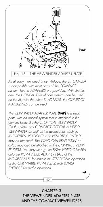
As already mentioned in our Preface, the SL CAMERAis compatible with most parts of the COMPACTsystem. Two SL ADAPTERS are provided. With the firstone, the COMPACT viewfinder systems can be usedon the SL; with the other SL ADAPTER, the COMPACTMAGAZINES can be used.
The VIEWFINDER ADAPTER PLATE [VAP] is a smallplate with an optical system that is attached to thecamera body like the SL OPTICAL VIEWFINDER. On this plate, any COMPACT OPTICAL or VIDEOVIEWFINDER as well as the accessories, such asMOVIELITES, READOUTS and REMOTE CONTROL,may be attached. The VIDEO CAMERAS (B&W orcolor) may also be attached to the COMPACT VIEW-FINDERS. You may fix e.g. the B&W VIDEO CAMERAonto the VIEWFINDER ADAPTER PLATE of theMOVIECAM SL for remote or STEADICAM operationor the ORIENTABLE VIEWFINDER with LONGEYEPIECE for studio operation.
Fig. 18 – THE VIEWFINDER ADAPTER PLATE
42
[VAP]

CHAPTER 3THE VIEWFINDER ADAPTER PLATE
AND THE COMPACT VIEWFINDERS
For detailed information about all these parts, pleaseconsult the COMPACT USERS GUIDE.
Caution:Before mounting the adapter plate, make sure thatall glass surfaces are meticulously clean.Care should be taken that the adapter sits plane onthe camera body.
43
CHAPTER 3THE VIEWFINDER ADAPTER PLATE
AND THE COMPACT VIEWFINDERS
As already mentioned in our Preface, the SL CAMERAis compatible with most parts of the COMPACTsystem. Two SL ADAPTERS are provided. With the firstone, the COMPACT viewfinder systems can be usedon the SL; with the other SL ADAPTER, the COMPACTMAGAZINES can be used.
The VIEWFINDER ADAPTER PLATE [VAP] is a smallplate with an optical system that is attached to thecamera body like the SL OPTICAL VIEWFINDER. On this plate, any COMPACT OPTICAL or VIDEOVIEWFINDER as well as the accessories, such asMOVIELITES, READOUTS and REMOTE CONTROL,may be attached. The VIDEO CAMERAS (B&W orcolor) may also be attached to the COMPACT VIEW-FINDERS. You may fix e.g. the B&W VIDEO CAMERAonto the VIEWFINDER ADAPTER PLATE of theMOVIECAM SL for remote or STEADICAM operationor the ORIENTABLE VIEWFINDER with LONGEYEPIECE for studio operation.
Fig. 18 – THE VIEWFINDER ADAPTER PLATE
42
[VAP]

CHAPTER 3THE VIEWFINDER ADAPTER PLATE
AND THE COMPACT VIEWFINDERS
45
CHAPTER 3THE VIEWFINDER ADAPTER PLATE
AND THE COMPACT VIEWFINDERS
44
[VAP]
[VAP]

CHAPTER 3THE VIEWFINDER ADAPTER PLATE
AND THE COMPACT VIEWFINDERS
45
CHAPTER 3THE VIEWFINDER ADAPTER PLATE
AND THE COMPACT VIEWFINDERS
44
[VAP]
[VAP]
CHAPTER 4THE SL MAGAZINES
CHAPTER 4THE SL MAGAZINES

CHAPTER 4THE SL MAGAZINES
CHAPTER 4THE SL MAGAZINES
CHAPTER 4THE SL MAGAZINES
Fig. 20 – THE SL MAGAZINES
49
The digital footage counter displays the remainingfootage; it is powered by its own on-board battery.When a magazine is attached to a powered camera,the magazine battery recharges automatically.In case nothing is displayed (which very rarelyhappens), simply mount the magazine to a poweredcamera in order to load the on-board battery and toreactivate the display. The magazine battery usuallyrecharges automatically during the shooting period.
After loading the magazine, use the ”preset buttons“ toinput the length of film loaded. By pressing the ”set button”, the footage counter storesthe input. It counts backward when the camera isrunning. The ”raw stock” display shows the length of remainingunexposed film.
CHAPTER 4THE SL MAGAZINES
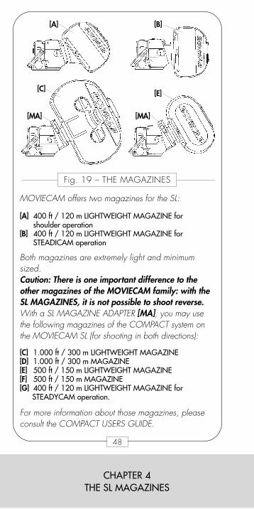
Fig. 19 – THE MAGAZINES
48
[A] [B]
[C] [E]
[MA] [MA]
MOVIECAM offers two magazines for the SL:
[A] 400 ft / 120 m LIGHTWEIGHT MAGAZINE for shoulder operation
[B] 400 ft / 120 m LIGHTWEIGHT MAGAZINE forSTEADICAM operation
Both magazines are extremely light and minimumsized. Caution: There is one important difference to theother magazines of the MOVIECAM family: with theSL MAGAZINES, it is not possible to shoot reverse.With a SL MAGAZINE ADAPTER [MA], you may usethe following magazines of the COMPACT system onthe MOVIECAM SL (for shooting in both directions):
[C] 1.000 ft / 300 m LIGHTWEIGHT MAGAZINE[D] 1.000 ft / 300 m MAGAZINE[E] 500 ft / 150 m LIGHTWEIGHT MAGAZINE[F] 500 ft / 150 m MAGAZINE[G] 400 ft / 120 m LIGHTWEIGHT MAGAZINE for
STEADYCAM operation.
For more information about those magazines, pleaseconsult the COMPACT USERS GUIDE.

CHAPTER 4THE SL MAGAZINES
Fig. 20 – THE SL MAGAZINES
49
The digital footage counter displays the remainingfootage; it is powered by its own on-board battery.When a magazine is attached to a powered camera,the magazine battery recharges automatically.In case nothing is displayed (which very rarelyhappens), simply mount the magazine to a poweredcamera in order to load the on-board battery and toreactivate the display. The magazine battery usuallyrecharges automatically during the shooting period.
After loading the magazine, use the ”preset buttons“ toinput the length of film loaded. By pressing the ”set button”, the footage counter storesthe input. It counts backward when the camera isrunning. The ”raw stock” display shows the length of remainingunexposed film.
CHAPTER 4THE SL MAGAZINES
Fig. 19 – THE MAGAZINES
48
[A] [B]
[C] [E]
[MA] [MA]
MOVIECAM offers two magazines for the SL:
[A] 400 ft / 120 m LIGHTWEIGHT MAGAZINE for shoulder operation
[B] 400 ft / 120 m LIGHTWEIGHT MAGAZINE forSTEADICAM operation
Both magazines are extremely light and minimumsized. Caution: There is one important difference to theother magazines of the MOVIECAM family: with theSL MAGAZINES, it is not possible to shoot reverse.With a SL MAGAZINE ADAPTER [MA], you may usethe following magazines of the COMPACT system onthe MOVIECAM SL (for shooting in both directions):
[C] 1.000 ft / 300 m LIGHTWEIGHT MAGAZINE[D] 1.000 ft / 300 m MAGAZINE[E] 500 ft / 150 m LIGHTWEIGHT MAGAZINE[F] 500 ft / 150 m MAGAZINE[G] 400 ft / 120 m LIGHTWEIGHT MAGAZINE for
STEADYCAM operation.
For more information about those magazines, pleaseconsult the COMPACT USERS GUIDE.

CHAPTER 4THE SL MAGAZINES
The construction of these magazines was based ontwo important aspects: size and weight.Regarding the size, these magazines were built asactive displacement - type magazines. This means thetake-up core continuously shifts from its start positiontowards the feed core, while the feed core itself shiftsbackward.Regarding the weight, these brand-new magazineswere made out of a carbon compound.Compared with aluminium magazines, this means lessweight but still the same stiffness and acousticproperties. Even though the magazines have torque motors,heaters and digital footage counters, they are still verylightweight and thus ideal for shoulder or STEADICAMoperation.The core holders are mounted mobile to allow anactive displacement. Be sure that no dust enters thetwo openings [A] at the bottom of the magazine.The core holders are identical with those of the othermagazines described in the MOVIECAM COMPACTor SUPERAMERICA USERS GUIDES.
Fig. 22a – SL MAGAZINE INTERIOR
51
[A] [A]
CHAPTER 4THE SL MAGAZINES
50
The small lock lever [A] is, when locked, secured by aspring steel safety tab [B].Open the magazines by pressing the safety tab downand turning the lever counter-clockwise. When closing,the safety tab automatically prevents an unintendedopening.Caution: Do not twist the safety tab!
Fig. 21 – THE SL MAGAZINES
[B][A]

CHAPTER 4THE SL MAGAZINES
The construction of these magazines was based ontwo important aspects: size and weight.Regarding the size, these magazines were built asactive displacement - type magazines. This means thetake-up core continuously shifts from its start positiontowards the feed core, while the feed core itself shiftsbackward.Regarding the weight, these brand-new magazineswere made out of a carbon compound.Compared with aluminium magazines, this means lessweight but still the same stiffness and acousticproperties. Even though the magazines have torque motors,heaters and digital footage counters, they are still verylightweight and thus ideal for shoulder or STEADICAMoperation.The core holders are mounted mobile to allow anactive displacement. Be sure that no dust enters thetwo openings [A] at the bottom of the magazine.The core holders are identical with those of the othermagazines described in the MOVIECAM COMPACTor SUPERAMERICA USERS GUIDES.
Fig. 22a – SL MAGAZINE INTERIOR
51
[A] [A]
CHAPTER 4THE SL MAGAZINES
50
The small lock lever [A] is, when locked, secured by aspring steel safety tab [B].Open the magazines by pressing the safety tab downand turning the lever counter-clockwise. When closing,the safety tab automatically prevents an unintendedopening.Caution: Do not twist the safety tab!
Fig. 21 – THE SL MAGAZINES
[B][A]
CHAPTER 4THE SL MAGAZINES
1) Clean darkroom / changing bag.
2) Lay the magazine down carefully onto footage counter side; roller assembly is facing you.
3) Lift magazine cover.
4) Check and clean magazine.Now put a core [G] on the film plate [F] until you hear a first “click”. Hold the plate and – simultaneously – turn the core gently to the left or right until you hear a second “click”. Only nowthe core is properly seated. In case you do not hear the“clicks”, the core holder [H] pin has
Fig. 23a – LOADING THE LIGHTWEIGHTSL MAGAZINES
53
[G]
[J]
[J][H]
[J] Core locks [H] Core holder release knob
[I][F]
CHAPTER 4THE SL MAGAZINES
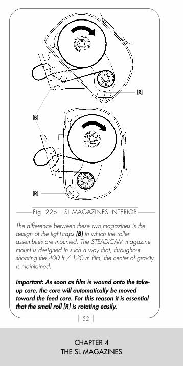
Fig. 22b – SL MAGAZINES INTERIOR
52
The difference between these two magazines is thedesign of the light-traps [B] in which the rollerassemblies are mounted. The STEADICAM magazinemount is designed in such a way that, throughoutshooting the 400 ft / 120 m film, the center of gravityis maintained.
Important: As soon as film is wound onto the take-up core, the core will automatically be movedtoward the feed core. For this reason it is essentialthat the small roll [R] is rotating easily.
[R]
[B]
[R]

CHAPTER 4THE SL MAGAZINES
1) Clean darkroom / changing bag.
2) Lay the magazine down carefully onto footage counter side; roller assembly is facing you.
3) Lift magazine cover.
4) Check and clean magazine.Now put a core [G] on the film plate [F] until you hear a first “click”. Hold the plate and – simultaneously – turn the core gently to the left or right until you hear a second “click”. Only nowthe core is properly seated. In case you do not hear the“clicks”, the core holder [H] pin has
Fig. 23a – LOADING THE LIGHTWEIGHTSL MAGAZINES
53
[G]
[J]
[J][H]
[J] Core locks [H] Core holder release knob
[I][F]
CHAPTER 4THE SL MAGAZINES
Fig. 22b – SL MAGAZINES INTERIOR
52
The difference between these two magazines is thedesign of the light-traps [B] in which the rollerassemblies are mounted. The STEADICAM magazinemount is designed in such a way that, throughoutshooting the 400 ft / 120 m film, the center of gravityis maintained.
Important: As soon as film is wound onto the take-up core, the core will automatically be movedtoward the feed core. For this reason it is essentialthat the small roll [R] is rotating easily.
[R]
[B]
[R]

CHAPTER 4THE SL MAGAZINES
55
Fig. 23c – LOADING THE LIGHTWEIGHTSL MAGAZINES
7) Pull approx. 50 cm film toward you. Unlock the left core holder by depressing the release knob [H]. Place film roll onto core holder - do not press toward magazine bottom (caution - film might be scratched!). Because of the displacement mechanism, great care must be taken that the film rolls on both sides are absolutely flatly wound.
8) Insert film from outside into magazine between maga-zine nose [C] in roller assembly and right roller [D].
9) Feed film into core slot so that no acute angle formswhen turning the core clockwise (See page 56 Fig.23d).Wind just enough film around take-up core tomake sure it will not accidentally slide out again. Wound-up film has to be flush with the core and lie flat on the small take-up plate [F]. Make sure that the film is not wound up below the recess of the small roller [R]. The film windings on the feed side must not protrude below plate – film might touch themagazine bottom.
[C] [D]
CHAPTER 4THE SL MAGAZINES
54
engaged in the hole of the core already at the beginning. It is not properly seated – have anothertry. Locked cores are released by pressing the release knob [H] on core holder. Checking core holders [I] and core locks [J]: By pressing the release knob [H] on top of the core holder, the threecore locks move inward.
Caution: In case of a malfunction of the core holder, do not disassemble – magazines should be serviced at a MOVIECAM Rental House.
From now on in darkness:5) Put film roll on empty can and place it to the
magazine left side.
6) Wind off just enough film to insert it in the roller assembly. Gently push the film into the slot between rail [A] and roller [B] until it emerges from the other side.
Fig. 23b – LOADING THE LIGHTWEIGHTSL MAGAZINES
[A] [B]

CHAPTER 4THE SL MAGAZINES
57
CHAPTER 4THE SL MAGAZINES
56
10) Close and latch magazine after checking that film is properly seated.
Caution: When closing the magazine, care shouldbe taken that nothing (e.g. changing bag, film bagetc.) is caught between magazine cover and base.
When the light is on again:11) Attach a loop protector and
12) Feed length of unexposed film into footagecounter.
Fig. 23d – CORE HOLDER
WRONG WAY
[E]
[R]
[F]
Notes:

CHAPTER 4THE SL MAGAZINES
57
CHAPTER 4THE SL MAGAZINES
56
10) Close and latch magazine after checking that film is properly seated.
Caution: When closing the magazine, care shouldbe taken that nothing (e.g. changing bag, film bagetc.) is caught between magazine cover and base.
When the light is on again:11) Attach a loop protector and
12) Feed length of unexposed film into footagecounter.
Fig. 23d – CORE HOLDER
WRONG WAY
[E]
[R]
[F]
Notes:

CHAPTER 5THE SL MAGAZINE ADAPTER
CHAPTER 5THE SL MAGAZINE ADAPTER

CHAPTER 5THE SL MAGAZINE ADAPTER
CHAPTER 5THE SL MAGAZINE ADAPTER

CHAPTER 5THE SL MAGAZINE ADAPTER
61
CHAPTER 5THE SL MAGAZINE ADAPTER
In order to mount the magazines from the COMPACTsystem, MOVIECAM offers an SL MAGAZINEADAPTER that simulates the COMPACT cameraopening. To mount this ADAPTER to the SL body, youhave to slit it onto the rail, like an SL MAGAZINE itself.Slide the SL MAGAZINE ADAPTER onto the railscarefully until you hear a ”click” and the adapter sitstight.The other side of the ADAPTER is similar to themagazine receptacle of the COMPACT TOP MOUNTADAPTER.The left side of the SL MAGAZINE ADAPTER can beopened, which makes threading the film easier.For information about the mentioned TOP MOUNTADAPTER and the other compatible MOVIECAMMAGAZINES, please consult the COMPACT USERSGUIDE.
Fig. 24 – THE SL MAGAZINE ADAPTER
60
Notes:

CHAPTER 5THE SL MAGAZINE ADAPTER
61
CHAPTER 5THE SL MAGAZINE ADAPTER
In order to mount the magazines from the COMPACTsystem, MOVIECAM offers an SL MAGAZINEADAPTER that simulates the COMPACT cameraopening. To mount this ADAPTER to the SL body, youhave to slit it onto the rail, like an SL MAGAZINE itself.Slide the SL MAGAZINE ADAPTER onto the railscarefully until you hear a ”click” and the adapter sitstight.The other side of the ADAPTER is similar to themagazine receptacle of the COMPACT TOP MOUNTADAPTER.The left side of the SL MAGAZINE ADAPTER can beopened, which makes threading the film easier.For information about the mentioned TOP MOUNTADAPTER and the other compatible MOVIECAMMAGAZINES, please consult the COMPACT USERSGUIDE.
Fig. 24 – THE SL MAGAZINE ADAPTER
60
Notes:

CHAPTER 6THE SL CARRYING HANDLE AND HANDGRIPS
CHAPTER 6THE SL CARRYING HANDLE
AND HANDGRIPS

CHAPTER 6THE SL CARRYING HANDLE AND HANDGRIPS
CHAPTER 6THE SL CARRYING HANDLE
AND HANDGRIPS

CHAPTER 6THE SL CARRYING HANDLE AND HANDGRIPS
Fig. 26 – THE RIGHT HANDGRIP
65
[B]
[A]
[C]
[D]
[22] [E]
For handheld operation, MOVIECAM offers anergonomically designed RIGHT HANDGRIP with built-inon/off button [A]. This button works like an ”alternatingswitch“: you can switch on the camera with thehandgrip button and switch it off with the other one [7]on the camera left side and vice versa. The RIGHTHANDGRIP is fixed to the MOVIECAM SL by means ofa small MOUNTING RAIL [B]. The mounting rail is slidonto the handgrip attachment [22] of the camera andhas a rosette with screw whose mobile latch permitseasier handling. Due to the rosette joint [C], the RIGHTHANDGRIP may be attached firmly at any verticalangle.A further accessory is the RIGHT HANDGRIPEXTENSION [D] that permits to adjust the handgripposition ergonomically. This extension facilitates thesimultaneous use of the RIGHT HANDGRIP andSTUDIO FOLLOW FOCUS.Do not forget to tighten the screws [E] and to connectthe handgrip plug to the on/off button outlet ( Fig.2) [1].
CHAPTER 6THE SL CARRYING HANDLE AND HANDGRIPS
The SL CARRYING HANDLE is mounted onto theaccessory dovetail bracket [3] and fixed with twoscrews. One screw [A] is tightened with an M5 Allenscrewdriver, the other by turning the knurled knob [B].
Make sure to mount the carrying handle firmly andproperly.
With the two knurled knobs [C], you may change theposition of the carrying handle.
The actual SL CARRYING HANDLE is only designed tocarry the camera equipped with the SL OPTICALVIEWFINDER. Other CARRYING HANDLES will soonbe designed for the SL equipped with otherViewfinders.
Fig. 25 – THE CARRYING HANDLE
64
[C]
[A]
[B]
[3]

CHAPTER 6THE SL CARRYING HANDLE AND HANDGRIPS
An extremely lightweight SL BASE PLATE has beendesigned for hand held operation with theMOVIECAM SL.This base plate consists of two parts:One part is attached to the camera, the other to thecamera head. To attach the camera to the camerahead, simply slide the plate rods into theircounterparts.
Caution: This base plate is available only for theStandard 35 configuration.
Fig. 28 – THE SL LIGHTWEIGHT BASE PLATE
67
CHAPTER 6THE SL CARRYING HANDLE AND HANDGRIPS
[B]
MOVIECAM provides an additional handgrip for thecamera left side that can be turned in any direction.Slide the handgrip onto the support rods and tighten atboth sides. To change the handgrip position, lift bothlatches [A] and loosen the screws [B].In the desired position, tighten the screws in bothrosette joints [C] and put the latches down again.
Caution: The LEFT HANDGRIP is only an additionalsupport - do n o t use as carrying handle (one-sidedstrain!).
Fig. 27 – THE LEFT HANDGRIP
66
[C][A]
[A]

CHAPTER 6THE SL CARRYING HANDLE AND HANDGRIPS
An extremely lightweight SL BASE PLATE has beendesigned for hand held operation with theMOVIECAM SL.This base plate consists of two parts:One part is attached to the camera, the other to thecamera head. To attach the camera to the camerahead, simply slide the plate rods into theircounterparts.
Caution: This base plate is available only for theStandard 35 configuration.
Fig. 28 – THE SL LIGHTWEIGHT BASE PLATE
67
CHAPTER 6THE SL CARRYING HANDLE AND HANDGRIPS
[B]
MOVIECAM provides an additional handgrip for thecamera left side that can be turned in any direction.Slide the handgrip onto the support rods and tighten atboth sides. To change the handgrip position, lift bothlatches [A] and loosen the screws [B].In the desired position, tighten the screws in bothrosette joints [C] and put the latches down again.
Caution: The LEFT HANDGRIP is only an additionalsupport - do n o t use as carrying handle (one-sidedstrain!).
Fig. 27 – THE LEFT HANDGRIP
66
[C][A]
[A]

CHAPTER 7THE INTERIOR OF THE SL
CHAPTER 7THE INTERIOR OF THE SL

CHAPTER 7THE INTERIOR OF THE SL
CHAPTER 7THE INTERIOR OF THE SL

CHAPTER 7THE INTERIOR OF THE SL
In order to adjust the movement to the properties anddimensions of the film material in use and at the sametime achieve an even more quiet and gentle filmtransport, a pitch adjustment control has been built intothe movement block of the SL.The pitch adjustment screw [Y] has no marks and nobuffer stop; the adjusting range is a whole turn of thescrew.While the camera runs with normal frame speed (24 -25 fps) and the material to be used, with an M5 Allenscrewdriver, by slowly turning clockwise or counter-clockwise, the position is looked for in which thecamera runs most smoothly and quiet. This position isjust a small segment of a screw turn.
Remark:The interior of the SL looks similar to that of the otherMOVIECAM cameras, but the rear film guides and therear buckle switches are mounted differently. Both rearfilm guides can be opened by pressing the releaseknobs [N1, N2] or closed by pushing the guidestowards the sprocket wheels. Notice that the upperwheel has, contrary to the one of the MOVIECAMCOMPACT, two rows of sprockets.The movement block and other parts, like the LOWERAPERTURE PLATE, the GROUND GLASSES, the mirrorshutter etc. are identical with those of the MOVIECAMCOMPACT. The description of those parts can be found in theCOMPACT USERS GUIDE.The UPPER APERTURE PLATE (gate) as well as thePRESSURE PLATE of theSL have newly designed grips– they are not compatible with other MOVIECAMcameras.
71
CHAPTER 7THE INTERIOR OF THE SL
[A] Movement block[B] Lock lever for lower aperture plate[C] Lower aperture plate[D1] Upper aperture plate[D2] Gate[E] Handle of upper aperture plate[F] Lock lever for upper aperture plate[G] Front film guide[H] Pressure plate[I] Pressure block[J] Lever of movement block[K] Inching knob[L1] Upper rear film guide[L2] Lower rear film guide[M1] Upper sprocket[M2] Lower sprocket[N1] Release knob for upper rear film guide [N2] Release knob for lower rear film guide[O] Buckle switch[X] Mounting rail for aperture plates (hided)[Y] Pitch adjustment screw
Fig. 29 – THE SL INTERIOR
70
[E]
[M1][L1]
[J]
[O]
[L2]
[A]
[N1]
[I]
[M2]
[N2]
[F][D1][G][H]
[D2]
[K]
[X][Y]
[C]
[B]

CHAPTER 7THE INTERIOR OF THE SL
73
Fig. 31a – CHANGING THE GROUND GLASSES
The ground glass of the MOVIECAM SL lies flat ontop of the mirror shutter and has a metal holder witha thread in the right front corner. Use theMOVIECAM COMBITOOL [T4] to exchange theground glass as follows:
1. Disconnect the camera
2. Remove lens or cavity cap.
3. Open the camera door. Turn the inching button [K] to clear the mirror shutter out of the way.
4. Screw the MOVIECAM COMBITOOL into the GROUND GLASS metal holder.
CHAPTER 7THE INTERIOR OF THE SL
72
Fig. 30 – GROUND GLASSES
The SL is equipped with the same GROUNDGLASSES as the other MOVIECAM cameras.GROUND GLASSES with the following markings areavailable:
STANDARD 35 formats:1 : 1.375 (Academy)1 : 1.375 + TV1 : 1.375 (camera + projector)1 : 1.375 + 1 : 1.661 : 1.375 + 1 : 1.751 : 1.375 + 1 : 1.851 : 1.661 : 1.66 (camera + projector)1 : 1.66 + TV1 : 1.66 + 1 : 1.851 : 1.78 (HDTV)1 : 1.851 : 1.85 (camera + projector)1 : 1.85 + TV1 : 2.35 (scope)
SUPER 35 formats:Superscope 35Superscope 35 (camera + projector)Superscope 35 + TVSuper 1 : 1.85Super 1 : 1.85 + TV

CHAPTER 7THE INTERIOR OF THE SL
73
Fig. 31a – CHANGING THE GROUND GLASSES
The ground glass of the MOVIECAM SL lies flat ontop of the mirror shutter and has a metal holder witha thread in the right front corner. Use theMOVIECAM COMBITOOL [T4] to exchange theground glass as follows:
1. Disconnect the camera
2. Remove lens or cavity cap.
3. Open the camera door. Turn the inching button [K] to clear the mirror shutter out of the way.
4. Screw the MOVIECAM COMBITOOL into the GROUND GLASS metal holder.
CHAPTER 7THE INTERIOR OF THE SL
72
Fig. 30 – GROUND GLASSES
The SL is equipped with the same GROUNDGLASSES as the other MOVIECAM cameras.GROUND GLASSES with the following markings areavailable:
STANDARD 35 formats:1 : 1.375 (Academy)1 : 1.375 + TV1 : 1.375 (camera + projector)1 : 1.375 + 1 : 1.661 : 1.375 + 1 : 1.751 : 1.375 + 1 : 1.851 : 1.661 : 1.66 (camera + projector)1 : 1.66 + TV1 : 1.66 + 1 : 1.851 : 1.78 (HDTV)1 : 1.851 : 1.85 (camera + projector)1 : 1.85 + TV1 : 2.35 (scope)
SUPER 35 formats:Superscope 35Superscope 35 (camera + projector)Superscope 35 + TVSuper 1 : 1.85Super 1 : 1.85 + TV

CHAPTER 1THE BODY OF THE SL SYSTEM
75
Film Gate with Gate Matte is integrated in the UPPERAPERTURE PLATE.Four UPPER APERTURE PLATES are available:
1 : 1.33 Full aperture1 : 1.375 Academy1 : 1.661 : 1.85
These aperture plates are made of extremely hardmaterial; the film touches the plate only in theperforation area. To avoid deposits, e.g. hair or filmdust, the fine Gate Matte [a] in the aperture plate isslightly recessed. The openings [b] for the registrationpins are located left and right of the gate. A guiderail [c] is attached to the aperture plate right side.Clean the aperture plate carefully and regularly - bestwith a vacuum cleaner. Only when it is badlysmudged – which will rarely be the case whenhandled properly and carefully – should you clean itwith a small brush or an orangewood stick.Caution: Never ever lubricate the aperture plate!
Fig. 32 – UPPER APERTURE PLATE
[d]
[c]
[a]
[e]
[b]
CHAPTER 7THE INTERIOR OF THE SL
74
When the COMBITOOL sits tight, pull out the groundglass gently.
5. Clean the GROUND GLASS gently with a very soft brush or a vacuum cleaner.
Caution: Do not touch with fingers or a solidobject! Do not moisten or wipe!
6. When screwing the COMBITOOL in or out, hold the ground glass holder only.
7. Push the GROUND GLASS gently all the way inuntil it rests against the stop and unscrew the COMBITOOL.
Caution: Never place the ground glass on itsedges. Do not force!
Fig. 31b – CHANGING THE GROUND GLASSES

CHAPTER 7THE INTERIOR OF THE SL
77
Insert the UPPER APERTURE PLATE on the rail [X] andpress forward gently while lifting the small lever [F]and bringing it back to its resting position (= lock)again. You can insert the aperture plate only parallelto the rail [X]!
Caution: In case the aperture plate is slanting, start inserting again.
Fig. 33b – MOUNTING OF THE UPPERAPERTURE PLATE
[X]
[F]
[E]
CHAPTER 1THE BODY OF THE SL SYSTEM
76
The image plane is located between the UPPERAPERTURE PLATE and the PRESSURE PLATE. Bothaperture plates (upper and lower) are attached tonotched brackets. For mounting, the UPPERAPERTURE PLATE has V-shaped notches at its top [d]and bottom [e] edges. These notches must beabsolutely clean to make sure the aperture plate canbe seated properly. The V-shaped bottom edge ofthe UPPER APERTURE PLATE, seated on the rail [X], isheld by a spring loaded lever. When removing theUPPER APERTURE PLATE,
1. push back the movement by turninglever [J] clockwise,
2. lift the small lever [F] and pull out UPPER APERTURE PLATE by its handle [E].
Caution: Be careful not to damage aperture plateor gate - this might have serious consequences!
Fig. 33a – MOUNTING OF THE UPPERAPERTURE PLATE
[F]
[E]
[J]

CHAPTER 7THE INTERIOR OF THE SL
79
To insert the LOWER APERTURE PLATE, follow thesteps described below:
1. Insert the LOWER APERTURE PLATE in the camera below the movement block;
2. pull LOWER APERTURE PLATE up and swing slightly toward camera front until it touches the rail [X].
3. Simultaneously, pull down the small lever [B] and press the lower part ofthe aperture plate in.
4. Lock the LOWER APERTURE PLATE in the camera by releasing the spring loaded lever [B].
CHAPTER 7THE INTERIOR OF THE SL
78
Like the upper plate, the lower one also has V-shaped notches at its top and bottom edges. The LOWER APERTURE PLATE has two slots for thepulldown claws. Notches, slots and surface of the aperture plate mustalways be clean – check regularly. Like the UPPERAPERTURE PLATE, the lower plate is attached tonotched brackets.
When removing the LOWER APERTURE PLATE,
1. slide back the movement block byturning lever [J];
2. press the small lever [B] down;
3. hold the released aperture plate [C] at its base and remove it.
Fig. 34 – LOWER APERTURE PLATE
[B]
[C]
[X] [J]

CHAPTER 7THE INTERIOR OF THE SL
81
The opening angle of the mirror shutter ranges from22,5° to 180°. To check or adjust the mirror shutterangle, proceed as follows:
1. Important: disconnect the camera.
2. Remove lens or cavity cap and open the cameradoor.
Fig. 36a – MIRROR SHUTTER
CHAPTER 7THE INTERIOR OF THE SL
80
In the front center of the front film guide [G], there is anopening for the PRESSURE PLATE [H]. This plate has tworaised surfaces [a] that hold the film in the gate planewith a spring loaded pin. Smudged surfaces inevitablycause film scratches! To clean the pressure plate,remove it as described below:
1. Swing the pressure block [I] backward.
2. Lift and remove the pressure plate.
3. Check PRESSURE PLATE and both surfaces thoroughly and - if necessary - clean them with lint-free cloth or orangewood sticks. Clean also the cavity at the rear of the pressure plate.
The spring is pressed into this cavity. The spring loadedsteel pin [B] in the pressure block presses the plate ontothe film with a certain force. When tapped lightly, thepin should move easily and spring back to its formerposition.
Fig. 35 – PRESSURE PLATE
[H]
[B]
[G]
[I]
[a]

CHAPTER 7THE INTERIOR OF THE SL
83
CHAPTER 7THE INTERIOR OF THE SL
82
3. Advance mirror shutter [a] with inchingknob [K] until shutter angle mark [b] isvisible in the lens mount.
4. Insert the MOVIECAM COMBITOOL [T4]in the small opening below this mark and turn it until you get the desired mirror shutter angle marked on the scale [b].
The mirror shutter has six positive stops for thefollowing shutter angles:
22,5°, 45°, 90°, 120°, 144°, 172.8°, 180°.
Fig. 36b – MIRROR SHUTTER
[T4]
[a]
[b]
Notes:

CHAPTER 7THE INTERIOR OF THE SL
83
CHAPTER 7THE INTERIOR OF THE SL
82
3. Advance mirror shutter [a] with inchingknob [K] until shutter angle mark [b] isvisible in the lens mount.
4. Insert the MOVIECAM COMBITOOL [T4]in the small opening below this mark and turn it until you get the desired mirror shutter angle marked on the scale [b].
The mirror shutter has six positive stops for thefollowing shutter angles:
22,5°, 45°, 90°, 120°, 144°, 172.8°, 180°.
Fig. 36b – MIRROR SHUTTER
[T4]
[a]
[b]
Notes:
CHAPTER 8THE POWER SUPPLIES
CHAPTER 8THE POWER SUPPLIES

CHAPTER 8THE POWER SUPPLIES
CHAPTER 8THE POWER SUPPLIES

CHAPTER 8THE POWER SUPPLIES
The integrated, thermostatically controlled heatingelements need approx. 15 W, even when the camerais not running. A stabilized 24 V (direct current) outlet, a 110 V /220 V (alternating current) outlet and a lead batterycharger are integrated in the POWER UNIT body.
Caution:Prior to connecting the power unit with the mains,check the given voltage and, if necessary, adjust theselector at the power unit rear accordingly!
When the camera is connected, you cansimultaneously charge a BATTERY BLOCK. You have toswitch on the main button [a] of the POWER UNIT notonly to operate the camera (switch lights red), but alsowhen the power unit serves as battery charger.Charging needs approx. 4-6 hours and is indicated bya green diode [d] lighting up. It fades out when thebattery is fully charged. Start charging by pressing thesmall button ”charge“ [c].Use the plug socket [e], secured by a 2 A automaticfuse, to charge a second battery block via its in-builtcharger or to supply e.g. an ”Obie light“ (max. 300 W/ 220 V) or a video recorder.
At the power supply unit rear, there are the voltageselector and the glass fuse 2 A slow (5 x 20 mm).
87
CHAPTER 8THE POWER SUPPLIES
[a] - Main switch[b] - Camera supply 24V / 8A stabilized[c] - Charge start button[d] - Charger control green LED[e] - Plug socket 110V or 220V[f] - Battery charger 24V / 1,3 A[g] - Connector 110V / 220V, 50/60 Hz[h] - Fuse
rear side 1 x 2 A glass fusefront side 8 A automatic fuse
2 A automatic fuse2 A automatic fuse2 A automatic fuse
The camera is powered either by the MOVIECAMPOWER UNIT or a MOVIECAM BATTERY BLOCK.The MOVIECAM SL is operated with a constantvoltage of 24 V. Under normal working conditions(approx. 25° C / color film in SL 400 ft - 120mMAGAZINE / 24 fps), the camera consumes 2,5A.The camera red diode lights up in case the voltagedrops below 20,5 V.
Fig. 37 – THE POWER SUPPLY
86
[a] [b] [c] [d]
[e] [f] [g] [h]

CHAPTER 8THE POWER SUPPLIES
Fig. 39 – CAMERA POWER SUPPLY
89
MOVIECAM provides two special coiled cables.The blue cable connects the mains with the POWERSUPPLY unit. The red cable connects the POWERSUPPLY unit or a BATTERY BLOCK with the SL.Both coiled cables may be stretched up to approx.2,5 m. Do not overstretch! As the voltage may drop up to 1 V per cable length(depending on the power consumption of the camera),do not use a longer cable.The camera cable can be easily plugged into thesloped connector [16].The leverage caused by connector length and cableweight resp. strain might damage the socketattachment. Therefore it is recommended to protect itagainst tension, e.g. by attaching the cable at the fluidor geared head. If the camera is properly connected to a power supply(loaded battery or main adapter), the display will lightup and the camera is ready to run. In case it does notlight up, you have to check with a meter if 24 V aresupplied. If this is the case, remove the small cover[17] and exchange the glass fuse 5 x 20 mm (6,3 A/ slow). If the display does not light up or the cameradoes not run after the exchange, the camera has to bechecked at the rental house.
[16] - Power receptacle[17] - Cover of the Main Fuse mount
[16] [17]
CHAPTER 8THE POWER SUPPLIES
The 7Ah 24V MOVIECAM BATTERY BLOCK is anassembly of lead cells.To charge, either connect the BATTERY BLOCK to thePOWER SUPPLY UNIT charger or use the built-incharger.The built-in charger [c] operates with 220 V.
Caution: Prior to operating the built-in charger witha different voltage, contact the rental house!
The green LED [b] lights up during charging period.After the BATTERY BLOCK has been fully charged, inapproximately 6 hours, the on-board charger switchesoff and the LED extinguishes.
To operate the MOVIECAM SL, plug the red CAMERACABLE into the 24 V outlet [a].
Fig. 38 – THE MOVIECAM BATTERY BLOCK
88
[a] [b] [c]

CHAPTER 8THE POWER SUPPLIES
CHAPTER 8THE POWER SUPPLIES
Notes:
91
The MOVIECAM DC-DC converter stabilizes the battery voltage to the maximum performance for the SL.
The input range is 18 – 36 V dcThe output range is 24 – 28 V dcThe max. output power is 150 W.
Operation:1. plug the battery cable to the power receptacle at
the base of the unit,2. adjust the desired voltage, e.g. 24 V, by means of
a 2mm screw driver introduced in the little hole onthe top of the unit [a],
3. connect the Adjustable Voltage Stabilizer to thecamera,
4. A strap [b] should help you securing the Stabilizerin order to prevent any restriction of the camera’sand operator’s movement.
Fig. 40 – ADJUSTABLE VOLTAGE STABILIZER
to camera
[a] [b]
from battery
90

CHAPTER 8THE POWER SUPPLIES
CHAPTER 8THE POWER SUPPLIES
Notes:
91
The MOVIECAM DC-DC converter stabilizes the battery voltage to the maximum performance for the SL.
The input range is 18 – 36 V dcThe output range is 24 – 28 V dcThe max. output power is 150 W.
Operation:1. plug the battery cable to the power receptacle at
the base of the unit,2. adjust the desired voltage, e.g. 24 V, by means of
a 2mm screw driver introduced in the little hole onthe top of the unit [a],
3. connect the Adjustable Voltage Stabilizer to thecamera,
4. A strap [b] should help you securing the Stabilizerin order to prevent any restriction of the camera’sand operator’s movement.
Fig. 40 – ADJUSTABLE VOLTAGE STABILIZER
to camera
[a] [b]
from battery
90

CHAPTER 9THREADING THE SL
CHAPTER 9THREADING THE SL

CHAPTER 9THREADING THE SL
CHAPTER 9THREADING THE SL

CHAPTER 9THREADING THE SL
Fig. 42 – THE MAGAZINE/ADAPTERMOUNTING RAIL
95
Contrary to the magazine receptacle of theSUPERAMERICA and the COMPACT, where themagazines are suspended on a rail and swingtowards the camera body, the magazine receptacle ofthe SL is designed with an upper and a lower rail [13]where the SL magazines are slid on.
On top of the mounting rail is a lock to secure themagazine or the adapter. By pressing the small knob[25a], this lock [25b] (Fig. 42) is released and themagazine or magazine adapter can be removed. The rear buckle switch [Q] is located on a plate in themiddle of the magazine receptacle. This plate serves at the same time as counterpart of thedoor lock.
[25a]
[Q]
[13]
CHAPTER 9THREADING THE SL
Fig. 41 – CAMERA DOOR LOCK
94
[13] - Mounting rail [25a] - Magazine / Magazine adapter release button[25b] - Magazine / Magazine adapter lock[P] - Door lock conterpart[Q] - Rear buckle switch
The door lock is designed in a way that, when turningthis lock, the door is pressed onto the body whichprotects it against light leakage.In case the door does not close properly, checkwhether the movement block is in its front position andthe film guides are closed.Only then the door can be locked properly.
[25a] [25b]
[13]
[Q]
[P]
[13]

CHAPTER 9THREADING THE SL
97
[13]
5a. Threading the film in the SL using theSL MAGAZINES
Slide the magazine onto the body until you hear a”click”.
Take care not to put the magazine on its edges, do not force!
Fig. 44 – THREADING FILM IN THE SL
[13]
CHAPTER 9THREADING THE SL
1. Open camera door.
2. Bring the movement to its rear position by turning the lever [J] clockwise.
3. Swing away the rear film guides [L1+ L2] by pressing the release knobs [N1+ N2]
4. Pull film loop (approx.10 cm) out of magazine.
Fig. 43 – THREADING FILM IN THE SL
96
[L1]
[L2]
[N1]
[N2]
[J]

CHAPTER 9THREADING THE SL
Attach magazine mounting claw to the adapter mounting rail. Insert film loop through the adapter in the camera. For easier threading, the adapter door [D] can beopened. Grab the film loop and swing magazine forward toward the adapter until it engages in the latch.
Fig. 45b – THREADING FILM IN THE SL
99
[MA]
[D]
CHAPTER 9THREADING THE SL
[MA]
98
Fig. 45a – THREADING FILM IN THE SL
5b. Threading the film in the SL using the SLMAGAZINE ADPTER [MA] and COMPACTMAGAZINES
Install the SL MAGAZINE ADAPTER like an SLMAGAZINE by sliding it onto the rail until you hear a ”click”.

CHAPTER 9THREADING THE SL
From now on same handling with SL or COMPACTMAGAZINES.
6. Pull film loop toward film gate and insert between film guides [L1 + L2] and sprocket-wheels [M1 + M2].
Fig. 47a – THREADING FILM IN THE SL
101
[M1]
[M2]
[L2]
CHAPTER 9THREADING THE SL
Caution: The latch of the adapter must be open! Do not crimp or fold the film!Do not forget: Lock the magazine on the adapter bypulling the adapter locking lever forward.
Fig. 46 – THREADING FILM IN THE SL
100
[D]

CHAPTER 9THREADING THE SL
From now on same handling with SL or COMPACTMAGAZINES.
6. Pull film loop toward film gate and insert between film guides [L1 + L2] and sprocket-wheels [M1 + M2].
Fig. 47a – THREADING FILM IN THE SL
101
[M1]
[M2]
[L2]
CHAPTER 9THREADING THE SL
Caution: The latch of the adapter must be open! Do not crimp or fold the film!Do not forget: Lock the magazine on the adapter bypulling the adapter locking lever forward.
Fig. 46 – THREADING FILM IN THE SL
100
[D]
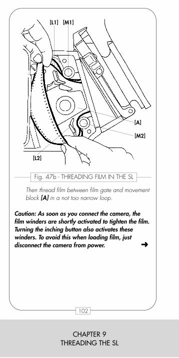
CHAPTER 9THREADING THE SL
7. Swing guide rails toward the sprocket-wheels [M1 + M2] by moving the latches [L1 + L2].
Fig. 48 – THREADING FILM IN THE SL
103
[L1]
[L2]
[M1]
[M2]
CHAPTER 9THREADING THE SL
Then thread film between film gate and movementblock [A] in a not too narrow loop.
Caution: As soon as you connect the camera, thefilm winders are shortly activated to tighten the film.Turning the inching button also activates thesewinders. To avoid this when loading film, justdisconnect the camera from power.
Fig. 47b - THREADING FILM IN THE SL
102
[M2]
[A]
[L2]
[M1][L1]

CHAPTER 9THREADING THE SL
9. To adjust loop length, turn inching knob [K] to the position (dot) marked ”LOOP”.
10. Form upper film loop to the ”LOOP” mark engraved on the rear side of the camera interior by depressing and turning the sprocket button [M1].
Fig. 50 – THREADING FILM IN THE SL
105
[M1]
[K]
CHAPTER 9THREADING THE SL
[J]
[A]
8. Turn the lever [J] with one hand gently counter-clockwise to move the movement block [A] into itsfront position. Simultaneously, turn inching knob [K] with the other hand to the left and right within the range of the ”TWIST“ mark to engage the pulldown claws gently and properly in the film perforations. Only then lock the movement block by further turning the lever [J] counter-clockwise until it engages in its front position.
Caution: Sprocket must engage properly in perforation!
Fig. 49 – THREADING FILM IN THE SL
104
[K1]

CHAPTER 9THREADING THE SL
9. To adjust loop length, turn inching knob [K] to the position (dot) marked ”LOOP”.
10. Form upper film loop to the ”LOOP” mark engraved on the rear side of the camera interior by depressing and turning the sprocket button [M1].
Fig. 50 – THREADING FILM IN THE SL
105
[M1]
[K]
CHAPTER 9THREADING THE SL
[J]
[A]
8. Turn the lever [J] with one hand gently counter-clockwise to move the movement block [A] into itsfront position. Simultaneously, turn inching knob [K] with the other hand to the left and right within the range of the ”TWIST“ mark to engage the pulldown claws gently and properly in the film perforations. Only then lock the movement block by further turning the lever [J] counter-clockwise until it engages in its front position.
Caution: Sprocket must engage properly in perforation!
Fig. 49 – THREADING FILM IN THE SL
104
[K1]
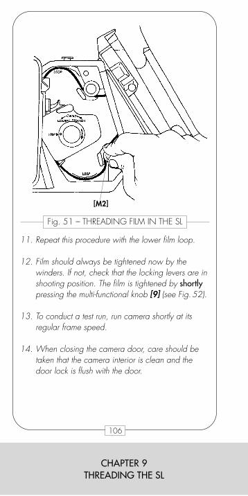
CHAPTER 9THREADING THE SL
107
Fig. 52 – DUST CHECK
When manually switching off the camera, theelectronic system of the MOVIECAM SL automaticallysets the mirror shutter to ”viewing position“. To inspectthe gate without opening the camera, set the mirrorshutter to shooting position by pressing the multi-functional button [9] for 2 seconds. Inspect the gate byeither shining a flashlight through the lens or removingthe lens. By pressing the multi-functional button, theletters ”dc“ are displayed on the control board. Thecamera can then be switched on only after pressingthe multi-functional button once again, which sets themirror shutter to ”viewing position“.
Caution:Before cleaning the film gate (with great care!),disconnect the camera to prevent possible accidentsor damage. When the camera is connected again,the electronic system is automatically reset (”standby“ mode); the mirror shutter, however, remains inthe shooting position and can be moved by pressingthe multi-functional button.
[9]
CHAPTER 9THREADING THE SL
11. Repeat this procedure with the lower film loop.
12. Film should always be tightened now by the winders. If not, check that the locking levers are inshooting position. The film is tightened by shortly pressing the multi-functional knob [9] (see Fig.52).
13. To conduct a test run, run camera shortly at its regular frame speed.
14. When closing the camera door, care should be taken that the camera interior is clean and the door lock is flush with the door.
Fig. 51 – THREADING FILM IN THE SL
106
[M2]

CHAPTER 9THREADING THE SL
107
Fig. 52 – DUST CHECK
When manually switching off the camera, theelectronic system of the MOVIECAM SL automaticallysets the mirror shutter to ”viewing position“. To inspectthe gate without opening the camera, set the mirrorshutter to shooting position by pressing the multi-functional button [9] for 2 seconds. Inspect the gate byeither shining a flashlight through the lens or removingthe lens. By pressing the multi-functional button, theletters ”dc“ are displayed on the control board. Thecamera can then be switched on only after pressingthe multi-functional button once again, which sets themirror shutter to ”viewing position“.
Caution:Before cleaning the film gate (with great care!),disconnect the camera to prevent possible accidentsor damage. When the camera is connected again,the electronic system is automatically reset (”standby“ mode); the mirror shutter, however, remains inthe shooting position and can be moved by pressingthe multi-functional button.
[9]
CHAPTER 9THREADING THE SL
11. Repeat this procedure with the lower film loop.
12. Film should always be tightened now by the winders. If not, check that the locking levers are inshooting position. The film is tightened by shortly pressing the multi-functional knob [9] (see Fig.52).
13. To conduct a test run, run camera shortly at its regular frame speed.
14. When closing the camera door, care should be taken that the camera interior is clean and the door lock is flush with the door.
Fig. 51 – THREADING FILM IN THE SL
106
[M2]

CHAPTER 10THE ACCESSORY BOXES
CHAPTER 10THE ACCESSORY BOXES

CHAPTER 10THE ACCESSORY BOXES
CHAPTER 10THE ACCESSORY BOXES

CHAPTER 10THE ACCESSORY BOXES
111
At the other end of the interface cable, there is anattachment plate to mount the boxes.Features and handling of the boxes, including theIRIS CONTROL device, the SPEEDBOX REMOTECONTROL WHEEL and the MAIN SYNC ADAPTER,are described in the COMPACT USERS GUIDE.
Please do not forget:Using the SPEEDBOX, you may shoot forward from 2 to 40 fps (not 50 fps, as with the COMPACT ). Ifyou want to shoot reverse (12 to 32 fps), you haveto use a COMPACT MAGAZINE.
Fig. 54 – THE ACCESSORY BOXINTERFACE
CHAPTER 10THE ACCESSORY BOXES
110
From the MOVIECAM family, three ACCESSORYBOXES can be used with the SL:the SUPER SPEED CONTROL BOX, the SYNCOBOX and the REMOTE CONTROL BOX. Those ACCESSORY BOXES must be new typeswhich have digital displays.The AATON CODE BOX cannot be used becausethe SL is not equipped with an LED to record thecode.
In order to use the SUPER SPEED CONTROL BOXand the SYNCO BOX, MOVIECAMsupplies aninterface cable. The REMOTE CONTROL BOX is provided either witha plug for attachment on the COMPACTVIEWFINDERS or with an SL connector. After removing the small cover [18] (see Fig. 5/page23) at the camera right side, you may plug theINTERFACE CABLE or the REMOTE CONTROLCABLE into the accessory connector and secure itwith an M5 Allen screw.
Fig. 53 – THE ACCESSORY CONNECTOR

CHAPTER 10THE ACCESSORY BOXES
113
CHAPTER 10THE ACCESSORY BOXES
112
To connect the SL REMOTE CONTROL CABLE withthe MOVIECAM SL camera, remove first the interfaceplug cover (Fig.5 [18]) on the right side of thecamera; then plug in the connector.When using viewfinders from the COMPACT system,you may also use the COMPACT REMOTECONTROL CABLE.
The REMOTE CONTROL BOX works as both on/offswitch [g] and ”remote“ READOUT. You can readexposed footage [b], frame speed [c], batterycondition [d], sync speed [e] and warning signs upto a distance of 10 m. As long as the REMOTECONTROL BOX is connected to the ready-to-shootcamera, the display [c] is on. By pressing the check -button [a], the preset frame speed or a warning signappears on the ”FPS“-display. It can be reset to ”0“by pushing the reset button [f].The ”FPS“ will beshown when you switch on the camera.
Fig. 55 – REMOTE CONTROL
[c]
[b]
[a]
[d]
[e]
[f]
[g]
Notes:

CHAPTER 10THE ACCESSORY BOXES
113
CHAPTER 10THE ACCESSORY BOXES
112
To connect the SL REMOTE CONTROL CABLE withthe MOVIECAM SL camera, remove first the interfaceplug cover (Fig.5 [18]) on the right side of thecamera; then plug in the connector.When using viewfinders from the COMPACT system,you may also use the COMPACT REMOTECONTROL CABLE.
The REMOTE CONTROL BOX works as both on/offswitch [g] and ”remote“ READOUT. You can readexposed footage [b], frame speed [c], batterycondition [d], sync speed [e] and warning signs upto a distance of 10 m. As long as the REMOTECONTROL BOX is connected to the ready-to-shootcamera, the display [c] is on. By pressing the check -button [a], the preset frame speed or a warning signappears on the ”FPS“-display. It can be reset to ”0“by pushing the reset button [f].The ”FPS“ will beshown when you switch on the camera.
Fig. 55 – REMOTE CONTROL
[c]
[b]
[a]
[d]
[e]
[f]
[g]
Notes:
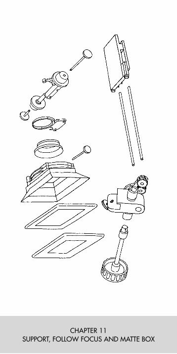
CHAPTER 11SUPPORT, FOLLOW FOCUS AND MATTE BOX
CHAPTER 11SUPPORT,, FOLLOW FOCUS
AND MATTE BOX

CHAPTER 11SUPPORT, FOLLOW FOCUS AND MATTE BOX
CHAPTER 11SUPPORT, FOLLOW FOCUS
AND MATTE BOX

CHAPTER 11SUPPORT, FOLLOW FOCUS AND MATTE BOX
117
[42] - Adjusting rings[43] - Locking lever
The support rod brackets on the MOVIECAM BASEPLATE are mobile. This is of advantage when shiftingthe optical axes for shooting in either STANDARD35 or SUPER 35 format.The rod brackets can be adjusted to either format byturning the asymmetrical rings [42]. Just press bothsliders [43] toward the center and turn the rings sothat each one of the two dots of the same color facethe center and the locating pins engage in the holes.
White = STANDARD 35 formatRed = SUPER 35 format
Fig. 57 – BASE PLATE (35/S 35)
[43]
[42]
[J]
CHAPTER 11SUPPORT, FOLLOW FOCUS AND MATTE BOX
116
Remarks:Apart from the SL LIGHTWEIGHT BASE PLATE, furthersupport systems of the MOVIECAM COMPACT canbe used together with the SL.There is one important difference, however, betweenCOMPACT and SL: the camera base of the SL isprovided with bore holes in ARRI axis standard only.SUPPORT RODS and, subsequently, LENS SUPPORT,MATTEBOX, STUDIO FOLLOW FOCUS etc. areattached to the base plate. You will not need theplate when using prime lenses, flanged FILTERHOLDERS, SUNSHADES and LIGHTWEIGHTFOLLOW FOCUS.
Caution: In case no original MOVIECAM base plate is used,do not screw the attaching screws further than 7 mm into the threaded sockets of the camerabase. Longer screws may damage the camera.When attaching the base plate, care should betaken that it sits flat on the camera base.
Fig. 56 – CAMERA BASE PLATE
[A]
[A] -ARRI axis

CHAPTER 11SUPPORT, FOLLOW FOCUS AND MATTE BOX
119
The MOVIECAM LENS SUPPORT can be adjusted toeither MOVIECAM (MC) [a] or ARRIFLEX (ARRI) [b]standard.The lower part of the support ring is attachedasymmetrically and may thus be turned 180° afterloosening the two M4 Allen fixing screws [c]. Thisshifts the ring´s central axis to the center of thestandard selected.
Fig. 58b – LENS SUPPORT
[b]
[c]
[c]
[a]
CHAPTER 11SUPPORT, FOLLOW FOCUS AND MATTE BOX
118
Mount the LENS SUPPORT to both SUPPORT RODSand tighten the lever [a].
Fig. 58a – LENS SUPPORT
[a]

CHAPTER 11SUPPORT, FOLLOW FOCUS AND MATTE BOX
119
The MOVIECAM LENS SUPPORT can be adjusted toeither MOVIECAM (MC) [a] or ARRIFLEX (ARRI) [b]standard.The lower part of the support ring is attachedasymmetrically and may thus be turned 180° afterloosening the two M4 Allen fixing screws [c]. Thisshifts the ring´s central axis to the center of thestandard selected.
Fig. 58b – LENS SUPPORT
[b]
[c]
[c]
[a]
CHAPTER 11SUPPORT, FOLLOW FOCUS AND MATTE BOX
118
Mount the LENS SUPPORT to both SUPPORT RODSand tighten the lever [a].
Fig. 58a – LENS SUPPORT
[a]
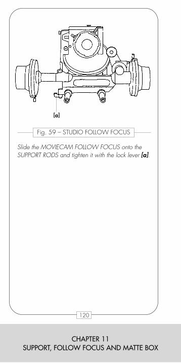
CHAPTER 11SUPPORT, FOLLOW FOCUS AND MATTE BOX
121
MOVIECAM provides several accessories for theSTUDIO FOLLOW FOCUS, e.g. focus extensionlevers [a] and flexible shafts [b] (easy to mount with asquared stick-in system [c]), as well as various gears[d] for the different lenses, e.g. COOKE, ZEISS,CANON, ANGENIEUX and MOVIELENS. Loosen the locking lever [e] and swing the smalldriver arm [f] toward the lens gear.
Fig. 60/61 – STUDIO FOLLOW FOCUS
[a][b]
[c]
[g] [d]
[d]
[e]
CHAPTER 11SUPPORT, FOLLOW FOCUS AND MATTE BOX
120
Slide the MOVIECAM FOLLOW FOCUS onto theSUPPORT RODS and tighten it with the lock lever [a].
Fig. 59 – STUDIO FOLLOW FOCUS
[a]

CHAPTER 11SUPPORT, FOLLOW FOCUS AND MATTE BOX
123
The MOVIECAM LIGHTWEIGHT FOLLOW FOCUSis used mainly for handheld operation. It has noscales; the distance has to be read directly off thelens barrel. After the squared support rod [a] isattached with a screw to the dove tail bracket [3] onthe camera front, mount the LIGHTWEIGHTFOLLOW FOCUS to this rod. Fix it with the screw [b]until the gear [c] attached to the driver arm engagesin the lens gear.
Fig. 64 – LIGHTWEIGHT FOLLOW FOCUS
[c] [3]
[b] [a]
CHAPTER 11SUPPORT, FOLLOW FOCUS AND MATTE BOX
122
For each lens, two magnetic discs [g] for individualmarks should be available – one for each side of theFOLLOW FOCUS.
Caution: When attaching these discs, the locatingpins [x] have to engage in the holes [y] .
The STUDIO FOLLOW FOCUS has a two geardrive. To change gear, press the small button [h] andsimultaneously move the wheel [i] forward orbackward.
Fig. 62/63 – STUDIO FOLLOW FOCUS
[g] [y] [x]
[i] [h]

CHAPTER 11SUPPORT, FOLLOW FOCUS AND MATTE BOX
125
This MATTE BOX is equipped with two filter stages[b] for altogether four 6.6”x 6.6” filters, two eachrotatable and sliding through, as well as two toothedfilter frames, operable with a rotary knob or flexibleshaft. The 4x filter stage has a receptacle [a] on therear for 6”, 138mm or 4 1/2” filter rings, as well asfor reflex prevention rings [e] and an additional 4” x4” filter stage. The 4x filter stage can be inter-changed against other filter stages. The MATTE BOXcan be swung open to the front for easy lenscleaning.By lifting the lever [d] on the top right side, unlock theMATTE BOX and swing it open to the front. Afterswinging it back, care should be taken that the leverlocks into place again. Additional holders [c] on theMATTE BOX serve for fastening French flags.
Fig. 67 – MATTE BOX
[b] [a]
[c][d]
CHAPTER 11SUPPORT, FOLLOW FOCUS AND MATTE BOX
124
The lever [d] at the rear of the LIGHTWEIGHTFOLLOW FOCUS is used to swing and adjust thesmall driver arm. A small gear, used for prime lenses(e.g. ZEISS), is attached to the end of this arm.
The operating wheels are attached to either left [e] orright [f] side of the follow focus.
Fig. 65/66 – LIGHTWEIGHT FOLLOW FOCUS
[f]
[f][d]
[3]
[b]
[d]
[a]
[f]
[e]

CHAPTER 11SUPPORT, FOLLOW FOCUS AND MATTE BOX
127
The MATTE BOX with its filter stages is attached mobileto two short rods [i]. The gear [j] engages in the toothedlower rod [k]. To move the MATTE BOX forward orbackward without having to move the whole bracket,loosen the locking lever [l] and turn the gear [j].The asymmetrical upper bracket [m] allows toadjust the MATTE BOX to the lens more precisely.Loosen the adjusting screw [n] and turn the knob [o] atthe rear end of the upper rod.
Caution: When using graduate filters, care should betaken that the filter, when in its lower position, doesnot touch the rods.
Fig. 70/71 – MATTE BOX
[o] [m]
[n]
[l]
[j]
[h]
[i]
[i] [k]
CHAPTER 11SUPPORT, FOLLOW FOCUS AND MATTE BOX
126
The MATTE BOX holds two filter stages for altogetherfour 6,6” x 6,6” filters, two each rotatable (knob [f])and sliding. Each filter stage has an attachment atthe rear for 6” , 138 mm or 4 1/2” filter rings, rubberdonuts (reflex prevention rings) [e] and an additional4” x 4” filter holder.
Some filter stages have a gear drive that may beoperated with the hand wheel [g] via a flexible shaftto move a toothed filter frame [h].
Fig. 68/69 – MATTE BOX
[f]
[g]
[h]
[e]

CHAPTER 12MISCELLANEOUS
CHAPTER 12MISCELLANEOUS

CHAPTER 12MISCELLANEOUS
CHAPTER 12MISCELLANEOUS

CHAPTER 12MISCELLANEOUS
131
In addition to the various cleaning tools, the cameraassistant needs only four other tools to work with theMOVIECAM SL:
With [T1], you attach the BASE PLATE to the camera.With [T2], you can mount and remove e.g. VIEW-FINDER, HANDGRIPS etc.[T3] is used for different tasks which should, however,best be left to the experts of the rental house.With [T4], you exchange the GROUND GLASS andset the mirror shutter angle.
Caution: Compressed air should only be used forblowing the magazines! Apart from this, highpressure does more harm than good, especially toglass surfaces.
Fig. 73 – TOOLS
[T1]8-10 mmscrewdriver
[T2]5 mm ballpointhex socket screwdriver (M5 Allenscrewdriver)
[T3]2 mm screwdriver
[T4]MOVIECAMCOMBITOOL
M5
CHAPTER 12MISCELLANEOUS
130
[8] - Connectors[A] - On/off switch
The ASSISTANT WORK LIGHT is mounted either ontop of the SL body, on top of a READOUT or on top ofa MOVIELITE like a flash to a still camera.After loosening the fixing screw, slide the light shoeinto one of the several brackets and tighten the screw.Disconnect the camera, then connect the short coiledcable (similar to that of the eyecup heater) to theconnector [8]. The light is switched on by turning itscap [A].
Always carry a spare bulb (24 V/4 W) with you.
Fig. 72 – ASSISTANT WORK LIGHT
[8]
[A]

CHAPTER 12MISCELLANEOUS
133
Now that you have read the whole manual, youalready know the SL by heart.
Just attach the tape measure to the hook and startshooting.
Good luck!
CHAPTER 12MISCELLANEOUS
132
The DIRECTORS FINDER allows to look for set-ups byusing the lenses of the MOVIECAM SL. GROUNDGLASSES, COMPACT VIEWFINDER systems andRIGHT HANDGRIP may be attached to the directorsfinder in the same way as to the camera.VIEWFINDER - even VIDEO CAMERAS, primelenses, an own GROUND GLASS (same format as inthe MOVIECAM SL) and RIGHT HANDGRIP areusually mounted to the DIRECTORS VIEWFINDER.The threaded socket (M5) at the rear of the finderand the pin hole can be used as finder attachment.
Fig. 74 – DIRECTORS FINDER

CHAPTER 12MISCELLANEOUS
133
Now that you have read the whole manual, youalready know the SL by heart.
Just attach the tape measure to the hook and startshooting.
Good luck!
CHAPTER 12MISCELLANEOUS
132
The DIRECTORS FINDER allows to look for set-ups byusing the lenses of the MOVIECAM SL. GROUNDGLASSES, COMPACT VIEWFINDER systems andRIGHT HANDGRIP may be attached to the directorsfinder in the same way as to the camera.VIEWFINDER - even VIDEO CAMERAS, primelenses, an own GROUND GLASS (same format as inthe MOVIECAM SL) and RIGHT HANDGRIP areusually mounted to the DIRECTORS VIEWFINDER.The threaded socket (M5) at the rear of the finderand the pin hole can be used as finder attachment.
Fig. 74 – DIRECTORS FINDER

APPENDIXCONNECTORS AND CABLES
Notes:
134
CHAPTER 12MISCELLANEOUS

APPENDIXCONNECTORS AND CABLES
Notes:
134
CHAPTER 12MISCELLANEOUS
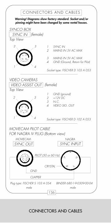
CONNECTORS AND CABLES
137
CAMERA FRONT(female)
Top View
GND+24 V Socket type: FISCHER D 103 A 051
24 V SUPPLY OUTLET
SELECT PILOTNC-50 HzGND-60HzCLAPPER for NAGRATRP/ 1,7 m SECPILOT (5V AC, PEAK-PEAK)selectable50Hz at 25 FPS, 24 FPS60 Hz at 24 FPSGND (Ground, Return for Pilot)
1
234
5
2 4
51
Socket type: FISCHER D 103 A 054
3
CAMERA RIGHT SIDE(female)
Top ViewSYNC OUT
(2 Amps. max.)
MOVIECAM DC SUPPLY CABLE
BATTERY CAMERA
+ 24 VGND
4 PINS XLR (male) 4 PINS XLR (female)
+ 24 V
1 1
2 233
4 4
CONNECTORS AND CABLES
CONNECTORS AND CABLES
136
SYNC INMAINS IN 5V AC MAX
MAINS IN 5V AC MAXGND (Ground, Return for Pilot)
12
34
SYNCO BOX(female)
Top View
2 3
41Socket type: FISCHER D 103 A 053
SYNC IN
GND (ground)+12V DCN.C.VIDEO SIG. OUT
1234
Socket type: FISCHER D 102 A 053
MOVIECAM PILOT CABLEFOR NAGRA IV PLUG (Bottom view)
PILOT (50 or 60 Hz)
MOVIECAM
CONNECTORS AND CABLES
VIDEO CAMERAS(female)
Top ViewVIDEO ASSIST OUT
2 3
41
SYNC INPUTSYNC OUTNAGRA
CRYSTALGND
CLAPPER
Plug type: FISCHER S 103 A 054 BINDER 680-1-9-0309-00-04male male
Warning! Diagrams show factory standard. Socket and/or pinning might have been changed by some rental houses.

CONNECTORS AND CABLES
137
CAMERA FRONT(female)
Top View
GND+24 V Socket type: FISCHER D 103 A 051
24 V SUPPLY OUTLET
SELECT PILOTNC-50 HzGND-60HzCLAPPER for NAGRATRP/ 1,7 m SECPILOT (5V AC, PEAK-PEAK)selectable50Hz at 25 FPS, 24 FPS60 Hz at 24 FPSGND (Ground, Return for Pilot)
1
234
5
2 4
51
Socket type: FISCHER D 103 A 054
3
CAMERA RIGHT SIDE(female)
Top ViewSYNC OUT
(2 Amps. max.)
MOVIECAM DC SUPPLY CABLE
BATTERY CAMERA
+ 24 VGND
4 PINS XLR (male) 4 PINS XLR (female)
+ 24 V
1 1
2 233
4 4
CONNECTORS AND CABLES
CONNECTORS AND CABLES
136
SYNC INMAINS IN 5V AC MAX
MAINS IN 5V AC MAXGND (Ground, Return for Pilot)
12
34
SYNCO BOX(female)
Top View
2 3
41Socket type: FISCHER D 103 A 053
SYNC IN
GND (ground)+12V DCN.C.VIDEO SIG. OUT
1234
Socket type: FISCHER D 102 A 053
MOVIECAM PILOT CABLEFOR NAGRA IV PLUG (Bottom view)
PILOT (50 or 60 Hz)
MOVIECAM
CONNECTORS AND CABLES
VIDEO CAMERAS(female)
Top ViewVIDEO ASSIST OUT
2 3
41
SYNC INPUTSYNC OUTNAGRA
CRYSTALGND
CLAPPER
Plug type: FISCHER S 103 A 054 BINDER 680-1-9-0309-00-04male male
Warning! Diagrams show factory standard. Socket and/or pinning might have been changed by some rental houses.