Embed Size (px)
Citation preview

Università degli Studi di Napoli Federico II Facoltà di Ingegneria
Enrico Barecchia
THE USE OF FRP MATERIALS FOR THE SEISMIC UPGRADING OF EXISTING RC STRUCTURES
Tesi di Dottorato XIX Ciclo
Il Coordinatore Prof. Ing. Federico M. MAZZOLANI
Dottorato di Ricerca in Ingegneria delle Costruzioni


A conclusione del “triennio” del corso di Dottorato di Ricerca sento di
dovere un primo, sentito e doveroso ringraziamento al Prof. Federico Massimo Mazzolani, per avermi concesso di vivere un’esperienza d’alto contenuto formativo e professionale.
Sono ugualmente riconoscente al Dr. Gaetano Della Corte che mi ha accompagnato nel corso degli studi, mettendo a completa disposizione la sua infinita esperienza e professionalità.
Un saluto va ai Professori Raffaele Landolfo, Bruno Calderoni e Gianfranco De Matteis come ed agli ingegneri Simeone Panico, Luigi Fiorino e Beatrice Faggiano, per la loro collaborazione durante le diverse attività di ricerca.
Sento di dovere un gradito omaggio ai miei Amici e colleghi, gli ingegneri Antonio Formisano ed Anna Marzo, ed alle “nuove leve” Mario D’Aniello, Matteo Esposto, Giuseppe Brando e Giovanni Cuomo, per avermi offerto la loro amicizia ed affetto.
Desidero ancora ringraziare l’ing. Giovanni Capasso, l’arch. Raffaele Hassler e l’ing. Roberto del Gado, per aver fornito i mezzi ed i materiali necessari alle esecuzioni delle diverse prove sperimentali.
E’ necessario dedicare un ringraziamento a Carmine Citro per l’aiuto fornito nelle diverse ricerche bibliografiche e per aver messo a disposizione, di Noi dottorandi, la sua esperienza di “uomo universitario”.
Voglio infine ringraziare Lina e tutta la mia famiglia per avermi sostenuto, ancora una volta, nel mio percorso formativo e professionale.


Index i
Chapter I
INTRODUCTION
1.1. GENERAL 1
1.2. MOTIVATION AND SCOPE OF THE RESEARCH 3
1.3. FRAMING OF THE ACTIVITY 5
Chapter II
THE USE OF FRP FOR THE STRUCTURAL IMPROVEMENT
2.1. INTRODUCTION 7
2.2. TYPES OF FIBRES 10
2.3. SEISMIC APPLICATIONS OF FIBER MATERIALS 20
Chapter III
SEISMIC BEHAVIOUR OF MASONRY INFILLED RC STRUCTURES
3.1. GENERAL 35
3.2. MODES OF FAILURE OF INFILLED FRAMES 37
3.3. STRENGTH AND STIFFNESS - MONOTONIC ACTIONS 42
3.4. STRENGTH AND STIFFNESS - CYCLIC ACTIONS 51
Index ii
3.5. DYNAMIC CHARACTERISTICS 57
3.6. NUMERICAL MODELLING 60
3.7. GLOBAL STRUCTURAL BEHAVIOUR 83
3.8. THE USE OF FRP FOR THE SEISMIC UPGRADING 91
Chapter IV
EXPERIMENTAL TESTS ON A RC STRUCTURE
4.1. INTRODUCTION 99
4.2. DESCRIPTION OF THE TESTED STRUCTURE 103
4.3. PUSHOVER TEST OF THE ORIGINAL STRUCTURE 109
4.4. REPAIRING AND UPGRADING OF THE TESTED STRUCTURE 115
4.5. THE STATIC CYCLIC TEST OF THE UPGRADED STRUCTURE 122
4.6. ORIGINAL VS UPGRADED STRUCTURE RESPONSE 127
Chapter V
EXPERIMENTAL TESTS ON A MASONRY INFILLED RC STRUCTURE
5.1. INTRODUCTION 129
5.2. THE PUSHOVER TEST OF THE ORIGINAL STRUCTURE 134
5.3. REPAIRING AND UPGRADING OF THE TESTED STRUCTURES 150
5.4. ORIGINAL VS UPGRADED STRUCTURE RESPONSE 159
Chapter VI
NUMERICAL MODELLING
6.1. GENERAL 161
6.2. MODELLING OF THE RC BARE FRAME STRUCTURE 163
6.3. DYNAMIC IDENTIFICATION OF RC BARE FRAME STRUCTURE 171

Index iii
6.4. DYNAMIC IDENTIFICATION OF THE MASONRY INFILL RC
STRUCTURE 175
6.5. MODELLING OF THE MASONRY INFILL RC STRUCTURE 184
Chapter VII
CONCLUSION REMARKS
7.1. CONCLUDING REMARKS AND FURTHER DEVELOPMENTS 197
REFERENCES


a mio nonno Gabriele per i suoi insegnamenti


1
Chapter I Introduction
1.1 GENERAL
In the environment of structural security of buildings in the seismic area, in the last years, it is developed an increasing interest on the definition of reinforced concrete infilled frames. Those structures have been object of several experimental tests and numerical analysis. This interest is due to the influence, on the structural seismic response, that had the infill panels, how is clearly demonstrated by recent earthquake event. In the past, was commonly accepted that the infill can enhance only the strength capacity of the structures under a lateral load; in reality, the effects are different, both on the global and local behaviour, and can be predicted with difficulty. Consequently, the control of plastic engagement and the damage assessment will be more complex if we consider also mechanical property of infill materials under a seismic load and the distribution of plastic hinge into a frame.
The existing experimental literature on masonry panels and concrete panels infilled in to a RC frame is wide. Generally, in all the conducted tests, an increasing of stiffness and strength and energy dissipation of infill frames is visible with respect to the bare frame. The most important parameters influencing the global behaviour are connected with the system geometry and to the material properties.
Nevertheless, although the scientific research is interested to this argument from over thirteen years, for many researchers the obtained results are not
2 Chapter I
sufficient for whole interpreter the structural behaviour of the infill. This aspect is associated to the validity of the tests and to the investigated parameters. Severally are the doubt connected to the interpretation of the seismic behaviour and to the collapse mechanism of each panel or of all the structure.
For first must underline that the experimental tests have been conducted in different countries in the world, adopting different materials, techniques and procedures, with a non direct comparison between the results. Furthermore, several tests have been done in reduced scale, and since the bricks are sensitive to the scale effects, these tests shown difficult in the interpretation of the results. Given the dimension of the specimens, the tests are more expensive and this imply the small number of the done tests with respect to the necessary number of tests for characterize all the parameters influencing the phenomena. It is not possible neglecting the tests procedure.
On the other hand is universally accepted that the response of a structural system and the collapse mechanism are influenced by several parameters but they are not quantified. The fundamental parameters are the geometric dimension of the panel, the materials mechanical properties and the building procedures. Another parameter influencing the structural behaviour is the ratio between the lateral stiffness of the bare frame and the lateral stiffness of the infill panel, tacking into account the presence of connectors, of openings, their position and dimension.
Until today, the major part of RC infilled frame was designed neglecting the presence of the infills considering only the weight of the infill. In not much case the infill panels are considered by a modelling with equivalent elements. There is a difficult to model the infill panels connected to the complexity of the phenomena: on one hand is necessary an instrument permitting to model all the important effects, for have a good modelling; on the second hand, is necessary have a simplified model able to be used in different cases.
A satisfactory numerical model must consider the in-plane and the out-of-plane behaviours, consider the brittle failure of the infill panels and consider the several collapse behaviour of the infill. Many numerical models are present in literature and can be subdivided into two categories in function of the adopted numerical simulation. The first group is based on finite element

Introduction 3
modelling of the panel, adopting the constitutive laws of the materials. The vantages of this approach are in the accuracy of the results, but presents serious computational problems as the numerical convergence. The second method adopts some equivalent structural elements simulating the infill panel behaviours. In this case is possible simulate the global structural behaviour of the infill frames.
In consequence of the mentioned problems, many design code not give any information about evaluate the effects of the infill walls. This implying the neglecting of the infill contributes in the seismic design restricting the design only to the bare frames. This certainly represents a simplification at disadvantage of the structural security. In fact the interaction between the frame and the infill wall change the structural response causing, for example, a brittle failure of the column, an in-plane force redistribution due to the torsional effects, the out-of-plane collapse of the infill and more over unexpected collapse mechanism.
1.2 MOTIVATION AND SCOPE OF THE RESEARCH
In the last years carbon fiber have been widely and successfully used for the seismic upgrading of existing structure, and sometimes as fundamental material for built new structures. Several studies and the increasing of the practical applications denote the growingly interest of the material application. FRP in form of fibre, when continuously and rigidly connected to the beams and columns of the frame, are able to carry out to absorb the horizontal forces, increasing the capacity to absorb seismic forces.
The first seismic application of FRP materials, thanks to their high strength, exhibited an effective performance for monotonic and seismic actions, while they were also efficient in the case of high intensity seismic loads. Last application of FRP allows the increase of the dissipation capacity by adopting appropriate details in the anchorage and on the application techniques.
The first application of FRP materials has been done by means of carbon fiber, in America, some years ago, it being based on the applying transversal fiber on concrete specimens for evaluate the increasing of axial strength and ductility for tanks to the effect of lateral confinement. In these experimental

4 Chapter I
tests the confinement offered by the carbon fiber have permitted to increase the axial force of about 20% and the ductility of 80%.
From the first experimental tests, is possible to carry out some important information, one of those is that the lateral confinement offered by composite material is not limited by the “yielding strength” as for the steel confinement of the stirrups, but is limited by he ultimate deformation of the material. This characteristic consent to have more important lateral contribute that can be translatable in a high axial increasing force.
Another advantage concerning the use of such fibre is related to considerable ductility of materials, allowing a stable behaviour of hysteresis loop for low and high deformation levels. On the other hand, some applications highlighted as the global performance of RC structures, properly stiffened through this type of materials, can be remarkably enhanced both in terms of collapse mechanism and for reducing the local damage of the members of the primary structure. Besides, another important aspect already highlighted is the one related to the simply application of composite materials, thanks to their low self weight. Finally, the possibility to use the contribution of FRP for seismic retrofitting of RC existing structures has been studied.
Such kind of application seems to be very interesting, since the application of FRP in some localized position of the existing structure, such as the ends of the columns, in the middle of the beams, in the beam-to-column joints, within existing structures could provide an effective way to produce an increasing of strength, stiffness and energy dissipation capacity, which is needed to make these structures able to overcome design earthquakes. Lightness, versatile ductility, strength and stiffness, architectural function as complementary or substitutive cladding elements of the existing ones, little interaction with beams and columns, are a few of the important advantages that make composite materials competing of others conventional and innovative existing systems in the seismic retrofitting field.
The interest of the seismic protection, by using of FRP, is on the change of collapse mechanism of reinforced concrete structure designed without any seismic criterion, in particular in the case of structure designed to resist to the gravity loads.
For this aim, a solution recently proposed during the research project “ILVA-IDEM An Intelligent Demolition” coordinated by Prof. F.M.

Introduction 5
Mazzolani consists in the use of composite materials for the seismic protection of existing RC structures.
The use of composite materials as seismic protection devices for new and existing framed structures represents an interesting solution within the international scientific research contest, addressed to the study of innovative strategies for preventing structural damages under earthquakes.
At moment, is scarceness the number of experimental tests conducted on real existing structures for study the behaviour and the efficacy of FRP for the seismic protection.
The lack of specific knowledge on such an application makes opportune to undertake investigations, under both theoretical and experimental points of view, aiming at assessing the possibility to use composite materials as seismic protection devices in the new and existing buildings by the definition of specific methodology.
1.3 FRAMING OF THE ACTIVITY
The current study will be addressed, on the one hand at global level, for determining the advantage of the seismic application of composite materials, and on the other hand at assessing proper design criteria of the single component so that to optimise the global response of building.
The type of FRP material considered in the experimental tests are the carbon fiber type. The main problem concerning the use of such a seismic protection is the possible occurrence of local and global buckling phenomena of the fiber, the efficacy of the adherence between the FRP and the concrete support and the efficacy of the anchorage.
A first research phase has been therefore aimed to define the structural behaviour of existing RC structure by means the execution of experimental tests on the existing structures. In this way is possible to evaluate the strength, stiffness and ductility of existing RC structures and to evaluate the shape of the collapse mechanism.
A second research phase has been instead addressed at the study of the reinforcement to modify the collapse mechanism or to increase the lateral displacement capacity of the reinforced structure.

6 Chapter I
In this direction, another full-scale experimental tests has been undertaken and adequate calculation tools based on the use of finite element software have been set up. The monotonic and cyclic behaviour of RC structures has been modelled by using advanced finite element software. The aim has been clearly to analyse by means of numerical simulation the response of the reinforced structure in both un reinforced and reinforced conditions.
The global behaviour of framed structures equipped with composite materials under seismic loads has been successively examined.
Numerical models effectively reproduced the stiffening and a dissipative effect of FRP, but there is a good agreement in term of collapse mechanism and base shear vs lateral displacement response.
The final phase of the study has concerned the comparison between both the experimental and numerical results of the analyzed structures. The results of this preliminary comparison have been given good results. The experimental data allowed to confirm the numerical studies, showing an increase of global ductility and the capacity of FRP to increase both strength and stiffness.

7
Chapter II The use of FRP for the structural improvement
2.1 INTRODUCTION
FRP is the acronyms of Fiber Reinforced Polymers used for indicate vastness category of composite materials constituting the actual frontier of technology of construction. Those materials are constituted by two base elements:
- Fiber materials having elevated material properties; - Polymeric matrix in which the fiber are included. The fibers constituting the reinforcement elements having high strength
properties and determining the mechanical behavior of composites, while, the matrix have the function of bonding the fiber and to guarantee the adhesion between the reinforcement and the support and, consequently, the transmission of the stress from the support to the reinforcement. Result is a material combining high strength and stiffness characteristics with excellent characteristics of lightness and durability.
The first realization of a work using composite materials concern the realization of a fiberglass boat – material progenitor of all the composite materials, constituted by glass fiber and polyester resins – realized on the 1942. Different typologies of composite materials as boron fiber and carbon fiber, appears on the 60th.
The high unitary price of those material, due essentially to the complex production process, have relegated from many years the use of FRP to

Chapter II
8
aeronautic and military applications. Nevertheless, the partial reduction of the prices, in particular for the carbon fiber, due to the optimization of the production process, have consented the use of those materials in structural engineering applications.
Figure 1: Typical composition of FRP materials.
Generally, composite materials are used for structural applications on
existing buildings. Some recent construction are integrally realized with FRP such as the foot bridge of Aberfeldy.
Composite materials are essentially of two types: - Fiber having elevated performance to apply in opera; - Pre-formed strips realized in plant. Mechanical properties of composite materials depend essentially on the
ones of single components used in the packaging and on the interaction between the two base materials. Fundamental factors characterizing the mechanical properties of composite materials are:
- fibers mechanical properties; - direction of application; - length; - cross section shape; - chemical nature of the fiber; - mechanical properties of matrix; - interaction behavior between fiber and matrix. In particular the interaction between fiber and matrix cause a re-
distribution of tension generated by external load. The principal role of the matrix is to transfer the stress between the fiber exploiting their shear strength and to protect the fiber from external atmospheric agent.

The use of FRP for the s tructural improvement 9
In any case composite materials present several relevant technologic characteristics:
- high mechanical properties; - low self-weight; - resistance to chemical attacks; - feasibility of applications; - adaptability to different types of support; - reversibility. For all this characteristics and for the aspect concerning the feasibility of
applications, the FRP constituting a reliable method for the structural reinforcement and the restoration of existing structures. In particular, the FRP are particularly indicated in which is requested the application of the material in areas with a difficulty of access.
Existing buildings request, in many times, the reinforcement intervention of principal frame for different reasons:
- cracks due to accidental causes, by designers errors by phenomena due to the errors in the design or in the realization, degradation of the materials, poor quality;
- necessity to increase the load carrying capacity of the structure for sustain an external load variation due to a variation of employment or for different functional necessity; - necessity of increase the seismic performance of the building. In the past, for this scope, was used, generally, steel plates or steel frames;
this technique gives good results but, in some cases, some technical hitch was visible as the error in the installation, the durability of the intervention, the corrosion of the elements.
Composite materials, thanks to the decrypted advantage as the lightness, resistance to the corrosion high mechanical properties and adaptability to the different supports, have consented to exceed all the problems connected to the older techniques.
Chapter II
10
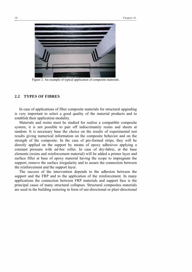
Figure 2: An example of typical application of composite materials.
2.2 TYPES OF FIBRES
In case of applications of fiber composite materials for structural upgrading
is very important to select a good quality of the material products and to establish their application modality.
Materials and resins must be studied for realize a compatible composite system; it is not possible to pair off indiscrimately resins and sheets at random. It is necessary base the choice on the results of experimental test results giving numerical information on the composite behavior and on the strength of the composite. In the case of pre-formed strips, they will be directly applied on the support by means of epoxy adhesives applying a constant pressure with ad-hoc roller. In case of dry-fabric, at the base elements (resins and reinforcement material) will be added a primer layer and surface filler at base of epoxy material having the scope to impregnate the support, remove the surface irregularity and to assure the connection between the reinforcement and the support layer.
The success of the intervention depends to the adhesion between the support and the FRP and to the application of the reinforcement. In many applications the connection between FRP materials and support face is the principal cause of many structural collapses. Structural composites materials are used in the building restoring in form of uni-directional or pluri-directional

The use of FRP for the s tructural improvement 11
fiber impregnated in situ of pre-fabricated obtained by an extrusion industrial process. The pre-formed elements are used in form pf plates or bars.
Most typical application typologies of FRP are essentially two: a) external wrapping of compressed elements as column and pier bridges; b) reinforcement of elements subjected to bending actions by applications
of the FRP in the traction side. In the first case are used the composite materials embedded in opera. The
scope of this type of applications is increasing the loading carrying capacity of the elements guaranteed by the transversal confinement or increasing the ductility. In case of member in bending the FRP materials are a valid alternative respect to traditional techniques such as the beton plaque, in which are used steel plates.
The advantages of FRP respect to the steel plates are essentially the capacity to follow the geometry of the surface of the support, the feasibility of the applications and the resistance to the corrosion. After the application, the composite materials must be protected to fire and UV ray by application of plaster or protective paint.
From the mechanical point of view, the behavior of composite materials is anisotropic with the consequences that the strength of the element is directly connected with the orientation of the fibers respect to the direction of the loads.
For load orthogonal to the weave of the fibers, the strength and stiffness of composite material are practically coincident to the resin ones, while, for load acting in the direction of the weave of the fiber, the strength and stiffness assumes their maximum values. This characteristic does not represent an inconvenience but consent, in several cases, the possibility to carry out a wise intervention applying the fiber only in the weak direction.
General
Fibers are made of very thin continuous filaments, and therefore, are quite difficult to be individually manipulated. For this reason, they are commercially available in different shapes. A brief description of the most used is summarized as follows:
Monofilament: basic filament with a diameter of about 10 μm. Tow: untwisted bundle of continuous filaments. Yarn: assemblage of twisted filaments and fibers formed into a continuous length that is suitable for use in weaving textile materials.

Chapter II
12
Roving: a number of yarn or tows collected into a parallel bundle with little or no twist. Several fibers typologies can be used for producing a composite material.
Commonly used in the civil applications are the carbon fibers, used for the structural reinforcement of concrete members for the elevated Young’ modulus; the aramidic fibers for the upgrading of masonry structures and, finally, the glass fiber.
For the masonry structures is preferable to use composite elements with a small elastic modulus because an element with an high stiffness can produce problems.
The stress-strain curve of FRP is elastic-linear; the constitutive law is give by sequent expression:
fdffuf fE ≤×= εσ
In which Efu is the elastic modulus of the fiber expressed as the ratio between the maximum strength and maximum deformation of the element.
Figure 3: Stress-strain diagram for different reinforcing fibers

The use of FRP for the s tructural improvement 13
The design strength capacity of composite elements is furnished by
sequent equation:
ukd l
m a
fR ηγ η
= ⋅⋅
In which fuk is the characteristic value of the ultimate strength of the fiber,
γm is the partial safety factor of the material and the product, this value change at the changing of the typologies of composite application; γRd is the strength model partial safety factor, this value is function of the strength mechanism (compression, tension, bending and shear); ηa is the environment condition partial safety factor and is influenced by the exposition of the reinforcement to the humidity, freeze and thermal loads.
Carbon fibers
Carbon fibers are used for their high performance and are characterized by high Young modulus of elasticity as well as high strength. They have an intrinsically brittle failure behavior with a relatively low energy absorption; nevertheless, their failure strength are larger compared to glass and aramid fibers. Carbon fibers are less sensitive to creep rupture and fatigue and show a slight reduction of the long-term tensile strength. The crystalline structure of graphite is hexagonal, with carbon atoms arranged on a basically planar structures, kept together by transverse Van der Waals interaction forces, much weaker than those acting on carbon atoms in the plane (covalent bonds). For such reason, their Young modulus of elasticity and strength are extremely high in the fiber directions and much lower in the transversal direction (anisotropic behavior). The structure of carbon fibers is not as completely crystalline as that of graphite. The term “graphite fibers” is however used in the common language to represent fibers whose carbon content is larger than 99 %. The term “carbon fibers” denotes fibers whose carbon content is between 80 and 95 %. The number of filaments contained in the tow may vary from 400 to 160000. The modern production technology of carbon fibers is essentially based on pyrolysis (e.g., the thermal decomposition in the absence of oxygen of organic substances), named precursors, among which the most frequent are polyacrylonitrile fibers (PAN), and rayon fibers. PAN fibers are first “stabilized,” with thermal treatments at 200-240 °C for 24 hrs, so their

Chapter II
14
molecular structure becomes oriented in the direction of the applied load. As a second step, carbonization treatments at 1500 °C in inert atmosphere to remove chemical components other than carbon are performed.
The carbonized fibers may then undergo a graphitization treatment in inert atmosphere at 3000 °C, to develop a fully crystalline structure similar to that of graphite. FRP composites based on carbon are usually denoted as C-FRP.
Aramid fibers
Aramid fibers are organic fibers, made of aromatic polyamides in an extremely oriented form. First introduced in 1971, they are characterized by high toughness. Their Young modulus of elasticity and tensile strength are intermediate between glass and carbon fibers.
Their compressive strength is typically around 1/8 of their tensile strength. Due to the anisotropy of the fiber structure, compression loads promote a localized yielding of the fibers resulting in fiber instability and formation of kinks. Aramid fibers may degrade after extensive exposure to sunlight, losing up to 50 % of their tensile strength.
In addition, they may be sensitive to moisture. Their creep behavior is similar to that of glass fibers, even though their failure strength and fatigue behavior is higher than G-FRP.
Figure 4: Stress-strain diagram for different reinforcing fibers

The use of FRP for the s tructural improvement 15
The production technology of aramid fibers is based on high-temperature
and high-speed extrusion of the polymer in a solution followed by fast cooling and drying. The fibers produced in this way may undergo a hot orientation treatment through winding on fast rotating coils (post-spinning) to improve their mechanical characteristics.
Aramid fibers are commercially available as yarns, roving, or fabrics. FRP composites based on aramid fibers are usually denoted as A-FRP.
Glass fibers
These are fibers commonly used in the naval and industrial fields to produce composites of medium-high performance. Their peculiar characteristic is their high strength. Glass is mainly made of silicon (SiO2 ) with a tetrahedral structure (SiO4 ). Some aluminium oxides and other metallic ions are then added in various proportions to either ease the working operations or modify some properties (e.g., S-glass fibers exhibit a higher tensile strength than E-glass).
The production technology of fiberglass is essentially based on spinning a batch made of sand, alumina, and limestone. The constituents are dry mixed and brought to melting (about 1260 °C) in a tank. The melted glass is carried directly on platinum bushings and, by gravity, passes through ad hoc holes located on the bottom. The filaments are then grouped to form a strand typically made of 204 filaments. The single filament has an average diameter of 10 μm and is typically covered with a sizing. The yarns are then bundled, in most cases without twisting, in a roving.
The typical value of the linear mass for roving to be used in civil engineering applications is larger than 2000 TEX. Glass fibers are also available as thin sheets, called mats. A mat may be made of both long continuous or short fibers (e.g., discontinuous fibers with a typical length between 25 and 50 mm), randomly arranged and kept together by a chemical bond. The width of such mats is variable between 5 cm and 2 m, their density being roughly 0.5 kg/m2. Glass fibers typically have a Young modulus of elasticity (70 GPa for E-glass) lower than carbon or aramid fibers and their abrasion resistance is relatively poor; therefore, caution in their manipulation is required. In addition, they are prone to creep and have a low fatigue strength.
Chapter II
16
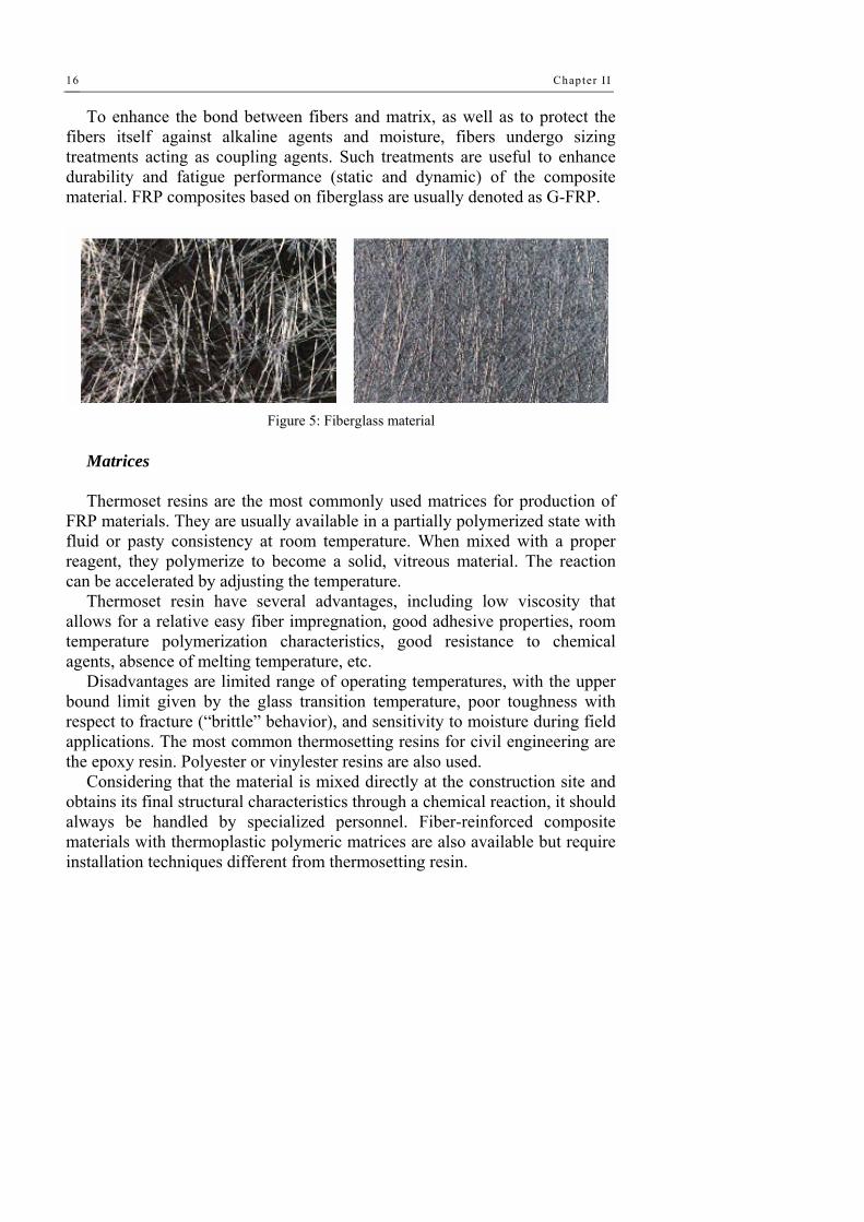
To enhance the bond between fibers and matrix, as well as to protect the fibers itself against alkaline agents and moisture, fibers undergo sizing treatments acting as coupling agents. Such treatments are useful to enhance durability and fatigue performance (static and dynamic) of the composite material. FRP composites based on fiberglass are usually denoted as G-FRP.
Figure 5: Fiberglass material
Matrices
Thermoset resins are the most commonly used matrices for production of
FRP materials. They are usually available in a partially polymerized state with fluid or pasty consistency at room temperature. When mixed with a proper reagent, they polymerize to become a solid, vitreous material. The reaction can be accelerated by adjusting the temperature.
Thermoset resin have several advantages, including low viscosity that allows for a relative easy fiber impregnation, good adhesive properties, room temperature polymerization characteristics, good resistance to chemical agents, absence of melting temperature, etc.
Disadvantages are limited range of operating temperatures, with the upper bound limit given by the glass transition temperature, poor toughness with respect to fracture (“brittle” behavior), and sensitivity to moisture during field applications. The most common thermosetting resins for civil engineering are the epoxy resin. Polyester or vinylester resins are also used.
Considering that the material is mixed directly at the construction site and obtains its final structural characteristics through a chemical reaction, it should always be handled by specialized personnel. Fiber-reinforced composite materials with thermoplastic polymeric matrices are also available but require installation techniques different from thermosetting resin.

The use of FRP for the s tructural improvement 17
Composite bars with thermoplastic matrix that may be bent at any time by means of special thermal treatment are currently being investigated.
Epoxy resins
Epoxy resins are characterized by a good resistance to moisture, chemical agents, and have excellent adhesive properties. They are suitable for production of composite material in the civil engineering field. The maximum operating temperature depends both on formulation and reticulation temperature.
For operating temperatures higher than 60 °C, the resin should be suitably selected by taking into account the variations of its mechanical properties. There are usually no significant restrictions for the minimum operating temperature. The main reagent is composed of organic fluids with a low molecular weight, containing a number of epoxy groups, rings composed by a oxygen atom and two carbon atoms:
Such materials may be produced by the reaction of epichlorohydrin with amino compounds or acid compound of bisphenol A. The epoxy pre-polymer is usually a viscous fluid, with viscosity depending on the polymerization degree. A reticulating agent (typically an aliphatic amine) is to be added to this mixture in the exact quantity to obtain the correct structure and properties of the crosslinked resin.
The reaction is exothermic and does not produce secondary products. It can be carried out at both room and high temperatures,
according to the technological requirements and the target final properties. The chemical structure of the resin may be changed on the basis of the chemical composition of the epoxy prepolymer. The most commonly used epoxy resin in composite materials for civil applications is the diglycidylether of bisphenol A (DGEBA).
Polyester resins
Polyester resins have a lower viscosity compared to epoxy resins, are very versatile, and highly reactive. Their mechanical strength and adhesive properties are typically lower than those of epoxy resins. Unsaturated polyesters are linear polymers with a high molecular weight, containing double C=C bonds capable of producing a chemical reaction. The

Chapter II
18
polymerization degree, and hence the molecule length may be changed; at room temperature the resin is always a solid substance.
To be used, polyester resin has to be dissolved in a solvent, typically a reactive monomer, which reduces the resin viscosity and therefore aids the fiber impregnation process. The monomer (typically styrene) shall also contain double C=C bonds, allowing cross-linking bridges between the polyester molecules to be created.
The reaction is exothermic and no secondary products are generated. It is usually performed at room temperature, according to technological requirements and target final properties. The chemical structure of polyester resins may be adapted either by changing the acid and the glycol used in the polymer synthesis or by employing a different reactive monomer.
The family of polyester resins for composite materials is typically composed of isophthalic, orthophthalic, and bisphenolic resins. For both high temperatures and chemically aggressive environment applications, vinylester resins are often used; they represent a compromise between the performance of traditional polyester resins and that of epoxy resins.
Typical application of FRP materials in civil structures
The major use of FRP in the civil construction regards the rehabilitation of existing RC and masonry structures. The progressive ageing of the structure, the necessity of upgrading the gravity load designed structure, the necessity of support the increment of loads due to a variation of the building use, require the necessity of a structural intervention and the reinforcement of the structural elements. In all the presented cases an intervention based on the use of composite materials can be think.
The FRP thanks to their lightness can be applied without the use of particularly tools and with a limited numbers of workers, in short time and without interrupt the activity into the building object of intervention. The most typologies of fiber used in the rehabilitation of reinforced concrete structure are the carbon fiber for their high strength and the possibility to select different elastic modulus. The aramidic fibers as the glass fiber are used in the case of masonry structures for the values of elastic modulus similarly to the one of the masonry.
The aramidic fibers are commonly used in the case of restoration of old and historical building where is not requested an elevated value of the elastic

The use of FRP for the s tructural improvement 19
modulus. In case of concrete structures, the FRP can be used for the upgrading of all the structural elements as column, beams and floor slabs. The reinforcement of compressed elements as the column occurs by a transversal wrapping of the element by several layer of composite materials in form of stripes with unidirectional fiber orientation.
The lateral confinement limits the lateral deformation of the column inducing on the concrete a tri-axial compression state. This technique produces an increasing of axial compression capacity, an enhancement of local and global ductility of the element and an increase of shear strength. A fundamental parameter for the results of this intervention is the geometry of the element to reinforce. In the case of circular section the wrapping technique gives the best results thanks top a uniform lateral confinement pressure; in the case of quadrate or rectangular section, lateral confinement is not uniform and it is concentrated in correspondence of the corner. In the case of stretched rectangular section the benefits of confinement are very limited.
The difference of the confinement give by the composite materials and by steel plates live in the limited lateral force in the case of steel plates (when the steel yields the lateral force remain constant), while, for the composite material the lateral force is limited only to the tensile collapse of the fiber.
The use of FRP for the reinforcement of member in bending is a good intervention due to the feasibility of the materials application, the capacity of materials to bond to the element surface and the lightness of elements. The application of the FRP, in order to enhance the potentiality of the intervention, must be done in absence of deformation and then the accidental and permanent loads must be removed. When the external loads acting, the FRP go in action and contribute to the resistance.
The FRP can be also applied with a pretension or with a favorable impressed deformation in order to optimize the efficacy. The effect of the composite material on the cross section mechanical behavior is to lower the neutral axis position, unload the steel rebars and implicating more compressed concrete.
The elastic modulus of the fiber consent to stiffener the reinforced element limiting the deformation.

Chapter II
20
The applications of FRP in form of strips give: - increase of stiffness to the members; - enhancement of carrying load capacity; - increasing of the ductility; - increase of resistance to fatigue; - limitation of cracked states. The reinforcement of element in bending request a shear reinforcement
(e.g. in case of simply supported beams the shear is maximum in correspondence of the lateral supports). This type of reinforcement can be done following two different ways: a) applying vertical uni-directional fibers having the function of a supplementary stirrup; b) applying unidirectional fibers inclined at 45° having the function to change the effects of folded bars.
2.3 SEISMIC APPLICATION OF FRP MATERIALS
General Generally speaking, FRP-material systems can be used for rehabilitating
civil engineering structures with the following purposes: - increasing flexural strength and stiffness; - increasing axial load capacity; - increasing shear (and torsion) strength; - increasing ductility and displacement capacity.
The first three objectives are not earthquake-engineering specific. Whereas, the last one is very typical of seismic upgrading activity. In earthquake engineering applications, also the first three design goals, in addition to the strength increasing, are often finalized to the structure ductility improvement, by eliminating brittle collapse mechanisms. For example: the shear strength increase can shift the failure mode towards a flexural-dominated one; the bending and compression strength increase of columns can allow satisfaction of modern hierarchy criteria in frame member strength distribution. However, FRP-material systems can also be addressed to directly increase the local ductility, e.g. by improving the compressive strain capacity of concrete by confinement of plastic hinge regions.
Then, within a specific earthquake-engineering perspective, the design

The use of FRP for the s tructural improvement 21
goals, to be satisfied using FRP materials, can be grouped into two main approaches:
- increasing local and/or global ductility and deformation capacity by favoring the most ductile failure mechanisms. This could involve changing of the type of plastic hinge (e.g. from shear to flexure) and/or the location of plastic hinges within the structure (e.g. from story to global mechanisms).
- increasing local ductility and deformation capacity of existing potential plastic hinges;
The difference is that in the second case the designer does not aim to change the type either the location of plastic hinges, as he does in the first case.
Papers collected from existing technical literature, which are briefly summarized in the next Section, have been grouped in the following main categories:
- Changing the failure mode from shear to flexure; - Avoiding lap-splice failure; - Strengthening partition walls; - Full-scale tests; - Special topics.
Categories 1 and 2 are the most typical, with papers dating back to 1999. Category 1 includes papers addressing the topic of favoring the most ductile failure mechanisms, by eliminating brittle shear failures and forcing the formation of ductile flexural plastic hinges, according to the above approach a). Contrary, category 2, includes papers dealing with the goal of improving ductility of existing potential plastic hinges, therefore, following the approach b).
Category 3 is relatively new, being all papers published in 2004. The idea of strengthening existing partition walls, thus making them effectively participating in the structural response up to collapse, opens the door to a perspective of application of FRP that only few years ago could be thought to be impracticable using FRP. It gives rise to the possibility of improving the global structural response by correcting irregularities (torsional response) in the building behavior.
Category 4 is includes papers dealing with both a) and b) approaches, in the sense that the tested FRP-strengthening systems could be addressed to satisfy of one or a combination of the generic design goals previously stated.

Chapter II
22
Category 5 includes papers which show different interventions for solving very specific problems of given structural types.
Categories 1: Changing the failure mode from shear to flexure Mosallam (2000) carried out physical tests on half-scale laboratory models
of interior beam-to-column joints of RC frame structures. Both un-reinforced and fiber composite reinforced joints were tested, showing appreciable increase in strength (up to 53%) and ductility (up to 42%) of joints. Ghobarah and Said (2001) tested a seismic rehabilitation system for shear-reinforcement deficient joints in RC framed structures. The proposed system, in case of exterior beam-column joints, consists on wrapping the joint area with a U-shaped G-FRP laminate, with the free ends of the U tied together by threaded steel rods, driven through the joint section, and a steel plate. In this way, they bypass the problem of passing through the existing beam with the fiber sheet, but allow the development of the full strength of the laminate preventing premature failure by delamination of the fiber wrap and forcing the formation of a flexural plastic hinge at the beam end.

The use of FRP for the s tructural improvement 23
Figure 6: The specimens and experimental results of tests conducted by Gobarah et al.(2001).
El-Amoury and Ghobarah (2002) present experimental results of tests
carried out on plain RC and G-FRP reinforced RC beam-column joints, showing, once again, the possibility to avoid the shear failure of the joint through the externally bonded composite reinforcement and forcing the plastic hinge to form by flexure at the beam end. In addition, they strengthened the bottom part of the beam end in such a way to integrate the existing non-adequately anchored steel reinforcement. The latter G-FRP sheets reduced fixed-end rotation effects improving the sub-assemblage stiffness. In all the retrofitting schemes, steel plates and angles were used for avoiding the composite sheets debonding.
Figure 7: The tests setup and the retrofitting schemes carried out by El-Amoury and Gobarah (2002).
The FRP-debonding problem was, instead, not encountered by Li et al.
(1999), who tested prototype-scale beam-column joints, both plain and reinforced, using an innovative hybrid FRP sheet. The hybrid FRP sheet was made of E-glass woven roving, plain carbon cloth and chopped strand mat and glass fiber tape with a vinyl-ester resin. This hybrid composite resulted in a low elastic modulus that helped, in the views of the Authors, eliminating the debonding of the sheets. The glass woven roving and carbon cloth were disposed with a bi-axial plain weaving which provided equivalent strength in both axial and hoop directions. Both the beam and the column were wrapped

Chapter II
24
with the bi-axial composite, having the care of increasing the radius of curvature in the corner deviations for reducing peeling stresses.
One of the (few) analytical studies of FRP-strengthened beam-to-column joints is reported by Parvin and Granata (2000), who developed numerical finite element models of exterior beam-to-column joints reinforced by using FRP-materials and compared them with the response of an un-reinforced control specimen. The reinforcement was supposed to be both in the longitudinal and transverse directions of both beam and column, with a fiber wrap placed at the corner deviations in order to absorb peeling stresses. Results showed an increase in the moment capacity of up to 37%.
Prota et al. (2003, 2004) carried out physical tests on joints reinforced using near surface mounted (NSM) FRP round bars passing through the joint and, thus, integrating the shear-induced tensile strength of the concrete in the joint. Both monotonic and cyclic tests were performed, again showing promising results in terms of both strength and ductility capacity improvement.
The possibility to control the local failure mode of RC structural members is testified also by the experimental and numerical results of Lee et al. (2004). These tests show that C-FRP wrapping can produce an increase of the member shear strength large enough to allow plastic hinging in bending.
Ghobarah and Khalil (2004) investigated the shear strengthening and ductility improvement of RC shear walls by using C-FRP sheets and C-FRP or steel anchors. Experimental test results illustrate the change of the collapse mechanism from shear to flexure thanks to the bidirectional (±45°) C-FRP reinforcement and the improvement of ductility thanks to the C-FRP wrapping of the two ends of the shear wall where high compressive strain demand can develop. Test results also emphasize the importance of an effective anchoring of the C-FRP sheets, in order to avoid premature debonding and consequent loss of strength, with a better response of the steel anchors with respect to the C-FRP anchors.
Tsonos (2004) carried out experimental tests on beam-to-column RC joints, explicitly including the presence of the horizontal slab. Both original and strengthened joints were tested, comparing jacketing by C-FRP sheets with the more classic RC jacketing. Both pre-earthquake strengthening and seismic repairing/upgrading of joints were experimented. Results show that the

The use of FRP for the s tructural improvement 25
original specimens failed by shear in the joint area, whilst the strengthened specimens, both with FRP and RC jackets, exhibited a flexural plastic hinge in the beam. Actually, a better response of the post-earthquake repairing with RC jacket with respect to the analogous FRP system was measured.
Figure 8: a) the test setup, b) failure mode of RC wall, c) failure mode of rehabilitated wall
(Gobarah et al 2004). Categories 2: Avoiding lap-splice failure Extensive experimental results on the effects of FRP wrapping of RC
rectangular columns with lap-splices of existing longitudinal bars are reported by Bousias et al. (2004). Their study includes variation of parameters such as the type of bar (smooth with hooked ends or straight with ribs), the length of splices, the number of FRP wrapping layers, the longitudinal length of the FRP wrapping, in addition to the bond properties of the bars. The Authors indicate that there was no appreciable improvement of the response in case of smoothed bars with hooked ends, independent of the examined parameter values. In case of straight ribbed bars, the increase of the number of C-FRP layers (from 2 to 5 layers) slightly improved the effectiveness of the wrapping, but the improvement effectiveness was not commensurate to the number of C-FRP plies and the effects were also strongly dependent on the length of the existing steel reinforcement lap-splices. In particular, the Authors indicate that the adverse effects of short lap-splices cannot be fully removed by the FRP-wrapping technique if the lap splicing is as short as 15 bar-diameters.
Experimental results on FRP-wrapping of RC rectangular columns are also

Chapter II
26
presented by Ilki et al. (2004). They tested specimens made by low strength concrete, reinforced by straight ribbed bars and with inadequate transverse reinforcement. Both specimens with lap-splices of longitudinal bars in the plastic hinge region and with continuous reinforcement were tested. The Authors indicate that when short lap-splices are present FRP wrapping does not improve the lateral inelastic response as much as they can, when ductility is limited by concrete crushing and longitudinal bar buckling (continuous reinforcement).
Analogous results were obtained by Yalçin and Kaya (2004), who conducted tests on RC columns with a rectangular cross section wrapped in the plastic hinge zone with C-FRP sheets. The Authors suggest that wet-lay-up C-FRP sheets do not provide the required confinement stress improving the bond-slip response in case of lap splices of longitudinal straight bars. Contrary, this technique was effective in case of continuous longitudinal bars.
Figure 9: Comparison between RC columns with and wiyhout C-FRP wrapping layers
(Yalçin and Kaya, 2004). Results of static cyclic tests on hollow square-section bridge piers (1:4
scaled), strengthened with both FRP wrapping and additional longitudinal FRP reinforcement are given in Pavese et al. (2004). The Authors notice that, in case of usual lap splices of existing longitudinal steel reinforcement at the base of the pier, FRP wrapping does not provide a large enough increase of confinement able to guarantee the transfer of the tensile forces in the cross section through the lapped steel bars. In this case, additional longitudinal FRP reinforcement is required. However, the basic problem of the foundation-anchoring of this newly added reinforcement must still be solved, in such that it proves to be effective under large tensile forces, but keeping the simplicity
The use of FRP for the s tructural improvement 27
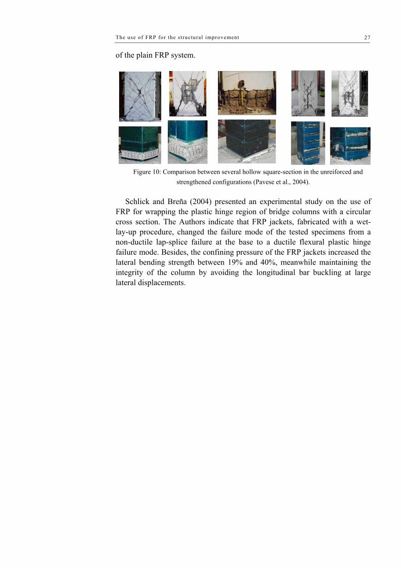
of the plain FRP system.
Figure 10: Comparison between several hollow square-section in the unreiforced and
strengthened configurations (Pavese et al., 2004). Schlick and Breña (2004) presented an experimental study on the use of
FRP for wrapping the plastic hinge region of bridge columns with a circular cross section. The Authors indicate that FRP jackets, fabricated with a wet-lay-up procedure, changed the failure mode of the tested specimens from a non-ductile lap-splice failure at the base to a ductile flexural plastic hinge failure mode. Besides, the confining pressure of the FRP jackets increased the lateral bending strength between 19% and 40%, meanwhile maintaining the integrity of the column by avoiding the longitudinal bar buckling at large lateral displacements.

Chapter II
28
Figure 11: Experimental specimens tested by Schlick and Breña (2004).
The possibility of using FRP wrapping for improving the inelastic response
of plastic hinges of circular-section RC columns, with lap-splices of longitudinal bars, is also indicated by the experimental results obtained by Chung et al. (2004), who tested bridge piers in a 1:2.5 scale.
Categories 3: Strengthening partition walls Erdem et al. (2004) tested a RC frame upgraded by using the shear strength
of hollow clay tile walls reinforced by means of diagonally placed C-FRP sheets, which were epoxy-bonded on the wall surface, extended on the frame members and connected to them by C-FRP anchor dowels. The test results were compared with those relevant to the bare frame and to the frame strengthened by using RC shear walls instead of the hollow clay tile walls. The results indicate that the lateral strength and stiffness of both the upgraded frames were about 5 times and 10 times those of the bare frame. However, the hollow clay tile walls failure mode was relatively more brittle, owing to the loss of strength of the C-FRP anchor dowels.
Experimental test results on the contribution of C-FRP laminates to stiffness, strength and deformation capacity of brittle walls made of hollow bricks are also given in Erol et al. (2004).
Garevski et al. (2004) presents experimental dynamic shaking table tests on

The use of FRP for the s tructural improvement 29
1/3-scale specimens of RC frame structures with infill walls strengthened with C-FRP strips epoxy-bonded on the inner and outer faces of the walls and also mechanically connected with anchor dowels. Their results indicate a remarkable reduction (-48%) of the lateral displacement demand to the strengthened specimen with respect to the un-reinforced one.
Figure 12: The three specimens used in Erdem et al. (2004).
Figure 13: Strengthening process of specimens used by Erol et al. (2004).

Chapter II
30
a) b)
c) d) Figure 14: a) the RC bare frame, b) the structure after the test, c), details of C-FRP
incorporation, d) the structure after the test (Garevski et al. 2004). Categories 4: Full-scale tests on existing real structures Pantelides et al. (2004) carried out pushover cyclic tests on 5 real RC
bridge bents. Three of them were tested as control specimens and the remaining two bents were tested after retrofitting with externally bonded FRP sheets. In addition, one of the control specimens was repaired and strengthened using FRP materials and then re-tested. The retrofitting system involving C-FRP materials consisted in both an additional flexural reinforcement in the longitudinal direction of columns and a C-FRP wrapping in the transverse direction of the plastic hinge regions, in addition to a shear reinforcement of the joint area. The bents ultimately failed always owing to lap-splices failure of existing steel reinforcement, but the strengthened structure exhibited larger strength and displacement capacity than the original bents, meeting the seismic performance objectives as set at the design stage.
One of the first extensive testing of an FRP-based system for seismic repairing/strengthening of RC structures is presented by Fyfe and Milligan (1998). The Authors also give several examples of practical applications to

The use of FRP for the s tructural improvement 31
bridge and parking garage structures. According to the Authors, two of these structures withstood the 1994 Northridge earthquake, performing as designed, what could be considered a full-scale test of an existing real structure.
Figure 15: a) RC bridge bents, b) experimental results of existing structure, c) experimental results of reinforced structure.
Categories 5: Special topics Johnson and Robertson (2004) presented the results of experimental tests
on ‘gravity-only’ slab-column connections failing in punching shear and retrofitted using C-FRP shear studs. Their results indicate promising effectiveness of the proposed technique in increasing the displacement capacity corresponding to the punching-type shear failure, which is important

Chapter II
32
for buildings located in seismic areas, where also the ‘gravity-only’ slab-column connections must maintain their vertical load bearing capacity up to the lateral displacements required by earthquakes.
Discussion of the collected literature Until now, the majority of both numerical and physical tests of FRP-
strengthened RC joints has been carried out considering externally-bonded FRP-materials applied in such a way to wrap up the joints with fibers often disposed both along the member axis and in the transverse direction, but never, passing through the beam-to-column node. This obviously reflects the actual difficulties of passing fibers through an existing monolithic joint. Unfortunately, this difficulty strongly limits the potentials of FRP materials, because of debonding problems, in the form of peeling-off failure at corners for the longitudinal FRP flexural reinforcement (where the reinforcing member intersects another surface) or delamination at the ends of shear-strengthening plies. In fact, the plain FRP system has often been proposed in association with steel anchoring devices (see, for example, Ghobarah and Said, 2001, El-Amoury and Ghobarah, 2002, Pavese et al., 2004), especially in the case of shear strengthening of RC beam-to-column joints.
The problem of anchoring FRP flexural reinforcement at corner deviations is strictly connected to the problem of eliminating or, at least, reducing bond-slip effects and improving the ductility and the structural integrity of plastic hinges by FRP-wrapping. In fact, the critical regions are quite always located at the ends of the member axis, where the intersection with another member or, very often, with a slab occurs. Besides, in case of existing gravity-load designed old structures, these critical regions are characterized by the lap-splicing of longitudinal steel reinforcement, with inadequate lap lengths. In all these cases, the impossibility to add a continuous FRP reinforcement in the critical section, which would reduce the fixed-end rotation effects, seems to have addressed the research towards the use of wrapping for clamping lap-splices and reducing bond-slip effects.
Existing experimental results on the effectiveness of FRP-wrapping are promising in case of columns with a circular cross section, such as it could be the case of bridge piers (Schlick and Breña, 2004, Chung et al., 2004).

The use of FRP for the s tructural improvement 33
Unfortunately, results for rectangular or square (either full or hollow) sections (more often encountered in building structures) are much less encouraging, indicating that the FRP-wrapping cannot fully solve the problem, especially in case of short lap-splices (Bousias et al., 2004, Ilki et al. 2004, Yalçin and Kaya, 2004, Pavese et al., 2004). Perhaps, this is the reason that induces several researchers to the use of the wrapping technique in conjunction with the addition of flexural reinforcement (El-Amoury and Ghobarah, 2002, Pavese et al. 2004), which reduces the tensile forces to be transmitted by the existing steel-reinforcement splices.
Two more observations can be made looking at existing literature papers: - experimental investigations are much more numerous than theoretic
studies; - there are no experimental studies, at the authors’ knowledge, dealing
with the problem of avoiding the formation of flexural plastic hinges in columns of building structures.
As far as the second aspect is concerned, it must be observed that, in case of existing gravity load designed RC building structures, the increase in flexural strength of columns required for moving plastic hinges to beams, could be relatively large, because of the small initial column over beam ratio of flexural strengths. Besides, the bending strength increase that can be achieved by means of externally bonded FRP reinforcement is limited by two problems:
1. peeling-off at corner deviations usually does not allow the development of the full composite action;
2. the FRP contribution to flexural strength increase reduces as far as the column axial force increases, because of the usually small compressive strength of externally bonded fiber composites.
The first problem could be bypassed, in case of RC framed structures, in several ways: a) by using special anchoring devices, such as steel plates and rods as proposed by El-Amoury and Ghobarah, (2002) and Pavese et al. (2004); b) by using near surface mounted bars, such as proposed by Prota et al. (2004), where round bars are to be inserted in small holes made with appropriate machines passing through the joint, with the care of avoiding the cut of existing steel reinforcement. Anyway, it must be emphasized that the anchoring devices make the plain FRP-system loose its simplicity. All these problems seem to strongly limit what can be done with FRP-material systems,

Chapter II
34
when the aim is to change the type of collapse mechanism by moving plastic hinges from columns to beams.
However, a large part of existing RC old buildings exhibit a slab-column connection at the least in one direction. In this case, some vertical holes can be locally made around the columns, without requiring temporary supports, in such a way to allow a continuous fiber application in the longitudinal column direction. Besides, in this case, the ideal beam for connecting column can be identified in slab, with a depth equal to the slab thickness and the width appropriately chosen by considering the effective contributing portion of slab. The latter observation implies that the column over beam bending strength ratio of the initial structure is relatively higher, due to the smaller plastic strength of beams, thus reducing the required flexural strength increase in columns.

35
Chapter III Seismic behaviour of masonry infilled RC structures
3.1 GENERAL
The effect of infills on the behaviour of frames has been widely investigated. Several attempts to analytically model the behaviour of infilled frames have been reported in literature.
Nevertheless, Axley and Bertero’s statement (1979) still holds true – “infilled frame structural systems have resisted analytical modeling”. This is partially due to the numerous parameters on which the behaviour of infilled frames depends, as well as to the high degree of uncertainty associated with most of those parameters.
From the point of view of structural response of infilled frames, the following aspects should be considered:
- the variability of the mechanical properties of infills, depending both on the mechanical properties of constituent materials (bricks, blocks, mortar, panels) and on costruction details;
- the variability of the frame-to-infill interface bahaviour; - location and dimensions of openings; - overall geometries: numbers of bays, numbers of stories, etc. As far as numerical modeling is concerned, the following problems should
be mensioned:

Chapter II
36
- the interaction between in-plane and out-of-plane response of infilled structures requires the use of very sophisticatede constitutive relations and complex elements;
- the highly non-linear response of infilled frames, even at low load levels, makes irrelevant the use of linear elastic elementsin most cases;
- the simulation of brittle behaviour may create serious numerical problems;
- finally, the pronounced softening which is to be expected after the maximum resistance of the structure is reached, may also create numerical problems.
A consequence of the numerous difficulties mensioned above, is that most of the current design codes and recommendations produced all over the world do not contain rules for the design of infilled frames, although the important effect of infills is recognized, expecially in case of cyclic actions (asseismica actions).
Thus, in common design practice, the presence of the so-called non-structural infill walls is ignored, the structural part of the bulding is analyzed and dimensioned and its members are reinforced accordlingly.
It has to be admitted that this commonly applied simplification may in some cases result in unsafe structures, especially under earthquake actions. In fact, when applying the simplified procedure, several potentially dangerous effects are neglected, namely:
a) significant damage or out-of-plane failure of infill walls could be the cause of casualties, even if minor or no damage is observed on the structural part of the structure;
b) premature brittle failure of columns may occur due to frame-infill interaction;
c) a significant unexpected torsional reponse of the structure may originate from a non uniform in-plane distribution of infill walls;
d) the serviceability limit states and low damageability requirements may not be satisfied.

Seismic behaviour of masonry infi l led RC structures 37
Figure 1: Typicall collapse mechanism of infilled structures.
3.2 MODES OF FAILURE OF INFILLED FRAMES
Many researchers have tested infilled frames subjected to in-plane shear forces or deformations imposed at thetop of the fame (Fig. 2). In all cases, a separation was observed between the infill wall and the frame elements. This
Chapter II
38
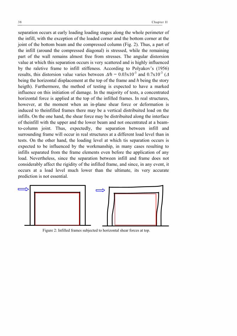
separation occurs at early loading loading stages along the whole perimeter of the infill, with the exception of the loaded corner and the bottom corner at the joint of the bottom beam and the compressed column (Fig. 2). Thus, a part of the infill (around the compressed diagonal) is stressed, while the remaining part of the wall remains almost free from stresses. The angular distorsion value at which this separation occurs is very scattered and is highly influenced by the raletive frame to infill stiffeness. According to Polyakov’s (1956) results, this distorsion value varies between Δ/h = 0.03x10⁻³ and 0.7x10⁻³ (Δ being the horizontal displacement at the top of the frame and h being the story heigth). Furthermore, the method of testing is expected to have a marked influence on this initiation of damage. In the majority of tests, a concentrated horizontal force is applied at the top of the infilled frames. In real structures, however, at the moment when an in-plane shear force or deformation is induced to theinfilled frames there may be a vertical distribuited load on the infills. On the one hand, the shear force may be distribuited along the interface of theinfill with the upper and the lower beam and not oncentrated at a beam-to-column joint. Thus, expectedly, the separation between infill and surrounding frame will occur in real structures at a different load level than in tests. On the other hand, the loading level at which tis separation occurs is expected to be influenced by the workmanship, in many cases resulting to infills separated from the frame elements even before the application of any load. Nevertheless, since the separation between infill and frame does not considerably affect the rigidity of the infilled frame, and since, in any event, it occurs at a load level much lower than the ultimate, its very accurate prediction is not essential.
Figure 2: Infilled frames subjected to horizontal shear forces at top.
Seismic behaviour of masonry infi l led RC structures 39
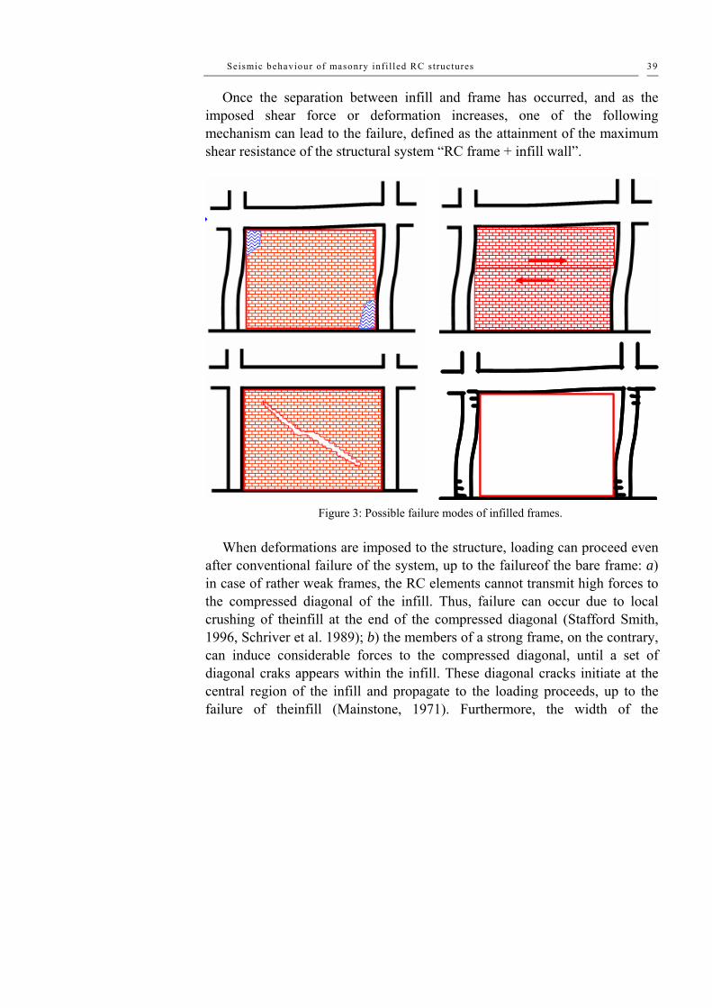
Once the separation between infill and frame has occurred, and as the imposed shear force or deformation increases, one of the following mechanism can lead to the failure, defined as the attainment of the maximum shear resistance of the structural system “RC frame + infill wall”.
Figure 3: Possible failure modes of infilled frames. When deformations are imposed to the structure, loading can proceed even
after conventional failure of the system, up to the failureof the bare frame: a) in case of rather weak frames, the RC elements cannot transmit high forces to the compressed diagonal of the infill. Thus, failure can occur due to local crushing of theinfill at the end of the compressed diagonal (Stafford Smith, 1996, Schriver et al. 1989); b) the members of a strong frame, on the contrary, can induce considerable forces to the compressed diagonal, until a set of diagonal craks appears within the infill. These diagonal cracks initiate at the central region of the infill and propagate to the loading proceeds, up to the failure of theinfill (Mainstone, 1971). Furthermore, the width of the

Chapter II
40
compressed diagonal seems to be a function of the lateral stiffness of the frame. In fact, Schriver et al. (1989) have measured widths of the compressed diagonal varying between 200mm (for the more flexible frames) and 900mm (for the stiffer ones); c) a veryweak masonry infill, with very low shear resistance along the bed joints can fail due to horizontal sliding along bed joints (zarnic and Tomazevic, 1985); d) finally, in the case of poorly designed infilled frames, failure can occur due to premature failure of columns or fo beam-column joints (Parducci and Mezzi, 1980).
Other studies have shown that the bahaviour of an infilled frame is heavily influenced by the interaction of the infill and its bounding frame. In most instances, the lateral resistance of an infilled frame is not equal to a simple sum of those of the infill and the bounding frame because frame–infill interaction can alter the load-resisting mechanisms of the individual components. At a low lateral load level, an infilled frame acts as a monolithic load resisting system. As the load increases, the infill tends to partially separate from the bounding frame and form a compression strut mechanism as observed in many early studies (e.g., Stafford Smith). However, the compression strut may evolve or not into a primary load-resistance mechanism of the structure, depending on the strength and stiffness properties of the infill with respect to those of the bounding frame.
On the basis of experimental observations, one can identify five main failure mechanisms of infilled frames. One is a purely flexural mode (mode A), in which the frame and the infill act as an integral flexural element. While this behaviour can occur at a low load level, where the separation of the frame and the infill has not occurred, it rarely evolves into a primary failure mechanism, except for tall slender frames that have very low flexural reinforcement in the columns. A low reinforcement ratio causes the early yielding of the flexural steel in the windward column when it is subjected to an uplift force. In most cases, infill panels tend to partially separate from the bounding frame at a moderate load level if the two are not securely tied. This is normally the case when the infills are treated as non-structural elements. The second (mode B) is a failure mechanism that is characterized by a horizontal sliding crack at the mid-height of an infill. This introduces a short-column behaviour and is therefore highly undesirable. In this situation, plastic hinges can form at the mid-height of the frame. For reinforced concrete

Seismic behaviour of masonry infi l led RC structures 41
frames, the columns will have a high tendency to develop shear failure, especially in a windward column that is subjected to a high tension. In the third mechanism (mode C), diagonal cracks propagate from one loaded corner to the other; and these can sometimes be jointed by a horizontal crack at mid-height. In this case, the infill can develop a diagonal strut mechanism that can eventually lead to corner crushing and plastic hinges or shear failure in the frame members. The fourth mechanism (mode D) is characterized by the sliding of multiple bed-joints in the masonry infill. Very often, this occurs in infills with weak mortar joints, and can result in a fairly ductile behaviour, provided that the brittle shear failure of the columns can be avoided. The fifth mechanism (mode E) exhibits a distinct diagonal strut mechanism with two distinct parallel cracks. It is often accompanied by corner crushing. Sometimes, crushing can also occur at the centre of the infill.
Figure 4: Experimental tests results (Marjani et al, 2002).
Marjani and Ersoy (2002) have recently investigated the behaviour and the
strength of reinforced concrete frames infilled with hollow clay tiles commonly used in Turkey. For this purpose, six six 1/3 scale, one-bay, two story reinforced concrete infilled frames were tested under reversed cyclic loading simulating the seismic effect. The lateral load was applied at the

Chapter II
42
second story level. In these tests, stiffness and strength degradation, ductility and drift index at different stages were investigated. Hollow clay tile infill increases both strength and stiffness significantly. The strength increase as compared to the bare frame is about 240% for specimens with unplastered infills and 300% for the plastered ones. Plastering both sides of the infill improves the behavior of the infilled frame considerably. Comparing plastered and unplastered specimens, the strength increase due to the plaster is about 25% and increase in initial stiffness is about 50 to 80%. Plaster also delays the diagonal cracking of the infill. Plastered infill, cracks at about 20% higher load as compared to the unplastered specimen. Plaster also improved the ductility significantly.
Figure 5: Experimental tests conucted by Marjani et al (2002).
3.3 STRENGTH AND STIFFNESS - MONOTONIC ACTIONS
It is well know that one of the most important beneficial effects of infills is the increase in lateral strength of the infilles frame, when compared to that of the bare frame.
As stated by Moghaddam and Dowling (1987), the parameters on which the strength of the infilled frames is depended may be divided into two categuries:
- those which are more quantificable and eay to generalize (such as geometry and strength of infill, relative stiffness of the infill with respect to the frame, strength and stiffness of the elements, amount of infill reinforcement, geometry of openings, etc.);

Seismic behaviour of masonry infi l led RC structures 43
- those which are difficult to quantify and generalize, although they migh be of the same importance and even moreso than the parameters of the first categories.
This latter category can contain such parameters as workmanship, type and size of units, interface bond condition, initial lack of fit between infill and frame, bond between mortar and bricks/bloks, etc.
In thefollowing, the role of several parameters is discussed, mainly on the basis of available experimental results. In some cases for which analyticalresults are mentioned as well.
The effect of the gap between infill and frame Mainstone (1972) tested small-scale steel frames filled with micro-concrete
infills, either in contact with the surrounding frame, or in some cases with a horizontal gap between the upper beam and the infill. He observed a considerable decrease of lateral strength (by 30% approximately), in cases where a gap was present. According to Parducci and Mezzi’s (1980) experimental results, the presence of vertical gaps between columns and infill caused a reduction of the strength of approximately 25% in comparison with the strength of infilled frames without gaps. In the same tests, the horizontal load correponing to the appearance of diagonal craks in infill walls was reduced by 45% approximately.
Moghaddam and Dowling (1987), who tested brick infilled steel frames with a side gap, report that they measured a decrease of 40% in the ultimate strength but nosignificant change in the cracking load. As Moghaddam ad Dowling state, both in their tests and in Parducci and Mezzi’s tests, the side gap were interrupted close to the corners of the infills.
Schmidt (1989) tested three frames-one bare frame and two frames infilled with masonry made of solid calcium silicate units. In one of the two infilled frames, the joint between infill wall and frame was filled with mortar, hile in the second infilled frame, the gap between infill and frame elements was filled with styrofoam. Static cyclic testing of the three frames showed that the lateral reistance of the infilled frame with mortar joints between infill and frame was by 52% higher than the lateral resistance of the bare frame. In the case of joints filled with styrofoam, the increase in resistance was only equal to 15%.

Chapter II
44
It should be noted, however, that the very low increase in lateral resistance observed in the tests may be attribuited to the unusually high strength of masonry infill walls, which led to prematre failure of the RC frames.
The effect of openings This parameter was experimentally investigated by several reserches:
Benjamin and Williams (1958) measured a 50% reduction of the ultimate strength in infilled frames having a l/3 long and h/3 high opening at the centre of the infill (l and h are respectively the length and the height of the infill). As Moghaddam and Dowling (1987) report, Dawe and Young (1985) did not observe any significant reduction of the ultimate strength of their infille frames in the presence of openings.
Liaw and Lee (1977) and Liauw (1979, 1980a) report on the results of monotonic tests on fuor-storey single-bay steel frames infilled with reinforced micro-concrete walls. One of the parameter investigated within their programmes was the presence and dimension of openings located at mid-span of infills.
The authors state that a change in the mode of failure was observed in cases where there were openings in the infills. In the case of solid infills, failure was due either to diagonal compression or to shear failure between infill with openings, the failure of lintel beams was responsible for the failure of the infilled frame.
Fiorato et al. have found that the reduction of the load resistance of an infilled frame is not proportional to the reduction of the cross-sectional area of an infill, fowing to openings. In their tests, openings that reduced the horizontal cross-sectional area of an infill by 50% led to a strength reduction of about 20–28% only.
Mosalam et al. have confirmed this observation. In their study, they tested two two-bay steel frames infilled with concrete block masonry that had window and door openings. One specimen had symmetric window openings with one opening in each bay, and the other had a window in one bay and a door in the other. These openings reduced the horizontal cross sectional area of an infill by about 17%. Their study has shown that the presence of openings led to a lower initial stiffness, but a more ductile behaviour. The maximum

Seismic behaviour of masonry infi l led RC structures 45
load resistance of the frame with symmetric window openings was almost the same as that without openings. However, the presence of a door opening reduced the load resistance by about 20%. They have observed that crack patterns were affected by the openings. Cracks tended to initiate at the corners of the openings and propagate towards the loaded corners, as opposed to the initiation of a horizontal crack at mid-height that propagated towards the loaded corners in a solid infill.
El-Dakhakhni et al (2004) have simulated, by a parametric stuy, the effect of interior and exterior walls in reinforced concrete and steel frames structures. The parameters studied included masonry strength, boundary conditions and different opening sizes, and they have studied the effect on stiffness and failure modes as well as the development of strut mechanism.
Infill walls within frame structures dramatically change the stiffness, strength and post-peak behaviour. In order to accurately predict the behaviour of infilled frames, the nonlinearities associated with the different constituent materials and the contact problem must be accounted for. In addition, accurate geometrical representation is required.

Chapter II
46
Figure 6: Numerical simulations carried out by El-Dakhakhni.
A similar study was conducted by Albanesi et al. (2004) in which several
typologies of openings have been considered into a trong frame and a weak frame. The infill is constituited by an hollow clay masonry with a ratio of holes equal to 60-70%.
Figure 7: Numerical simulations carried out by Albanesi (2004).

Seismic behaviour of masonry infi l led RC structures 47
Effect of shear connectors As mentioned before, this parameter was investigated by Liauw and Lee
(1977) and Liauw (1979, 1980a). The authors observed a change in the failure mode due to to the presence of shear connectors, accompanised by an increase both in stiffness and in strength. Similar beneficial effects of shear connectors were observed also in Mallck and Garg (1971).
Sugano and Fujimura (1980) have tested 1:3 scale RC frames infilled according to several common techniques. Unfurtunately, the test results do not be observed, since identical frames without shear connectors were not tested.
On the contrary, the beneficial effects of shear connectors can be observed in the results of Higashi et al. (1980), where the addition of three precast panels to an RC frame led to an increase in strength of 210%, while the addition of three precast panels connected at their top and bottom to the beams by means of shear connectors led to an increase in strength by 330% with respect to the bare frame.
Yuzugullu (1980) observed similar features in his tests. He tested RC frames infilled by means of multiple precast RC walls: his results shown an average increment of strength, stiffness and maimum lateral displacement respectively equal to 25%, 35% and 28%.
Several methods of fixing RC cast-in-place infills on the surrounding RC frame were investigated by Hayashi et al (1980). The effects of fixing on the strength of frames give an increment of the strength equal to 50%.
Finally, several researches have tested frames, in which the horizontal reinforcement of the infills, or their vertical reinforcement, or both, were anchored into beams, or columns, or beams and columns, respectively (Zarnic and Tomazevic, 1985, 1988, Jurina, 1977, Klingner and Bertero, 1976, 1977, 1978). Although it is not always possible to detect the its effect is beneficial, both in increasing the strength and in improving the hysteretic behaviour of infilled frames.

Chapter II
48
The effect of strength of the infill Type of units A better behaviour of infilled frames is expected when solid bricks or
blocks are used in infill wall since, usually, solid units are of higher strength than highly perforated units. Therefore, walls made of solid units are higher strength than walls made of perforated units. Furthermore, masonry made of solid units is expected to exhibit better behaviour when subjected to cyclic actions, because this type of masonry disintegrates less than masonry made of hollow units. This was, in fact, proved by Parducci and Mezzi (1980), who used in their tests either semi-solid or hollow bricks.
Strength of mortar A better quality of mortar is expected to increase both the cracking load of
the infill and the ultimate resistance of the infilled frame. In fact, the use of mortar of better quality (for the same quality of masonry units) leads to better bond characteristics between mortar and units in the joints and, therefore, to higher cracking load. Alternatively, at ultimate load, crushing and disintrgration of masonry will be delayed for higher strength of the masonry.
This, however, holds true within certain limits: when the masonry becomes excessively strong with respect to the surrounding RC frame, premature failure of the frame elements may occur and, therefore, the strength of the whole system may drastically reduced.
Tests made by Dawe and Young (1985) on steel infilled frames have shown a beneficial effect of increasing the mortar strength on both cracking and ultimate resistance of the frames.
On the contrary, the experimental results of Kadir (1974), as well as the results of Stylianidis (1985), do not show a significant influence of this parameter on the strength of infilled frames.
Note that in the case of tests by Stylianidis, the compressive strength of the mortar varied between 2.4 MPa and 12.4 MPa. The insignificant influence of the mortar strength on the lateral strength of infilled frames can be explained on the basic of the sequence of damages as reported by the author, who states

Seismic behaviour of masonry infi l led RC structures 49
that the appearance of cracks in RC columns preceded the cracking of infills, and the formation of plastic hinge in columns preceded the failure of the infill, even in the case of mortars having a compressive strength of 2.4MPa.
Effect of reinforcement of infilIs Within several research programmes, one of the investigated parameters
was the reinforcement percentage of infills (mainly the ratio of the horizontal reinforcement). Zarnic and Tomazevic (1985) have tested RC frames filled with brick masonry walls, which in some cases were horizontally reinforced (p = 0.29%). The experimental results do not show any significant influence of the infill reinforcement on the lateral strength of infilled frames. This, however, may be attributed to the poor bond conditions between reinforcing bars and mortar, as well as to the early cracking of the infill along the bed joints.
On the contrary, Jurina (1977), who tested RC frames with reinforced brick infills, observed a significant increase in lateral strength of the infilled frame thanks to the reinforcement of the infill. In fact, in the case of plain infill, the ratio between laterali strength of the infilled frame and lateral strength of the bare one was equal to 4.0, while in the case of reinforced infill, the value of this ratio was equal to 5.4.
Brokken and Bertero (1981) tested three-storey RC frames infilled either
with RC or with brick or block masonry. They did not observe any significant influence of the horizontal reinforcement of infills on the lateral resistance of infilled frames. It sbould be noted, however, that, given the number of parameters investigated in each specimen, it is very difficult to isolate each parameter and draw conclusions about its influence on the behaviour of the test specimens.
It is believed that a more systematic investigation is needed in this respect. Nevertheless, one should keep in mind that the role of the reinforcement in infills is expected to be beneficial in the case of cyclic actions, in preventing premature disintegration of infills, thus increasing the ductility of the system.
Effect of relative beam-column stiffness

Chapter II
50
This parameter was investigated by Parducci and Mezzi (1980). In their
tests, the variation of the beam stiffness was quite large (from 1 to 4). However, no significant effect on the lateral resistance of the infilled frames was observed. It should be noted that a more meaningful parameter would possibly be the relative beam-to-column flexural strength. In fact, in cases of large cyclic actions (e.g. earthquakes), strong beams connected to weak columns may lead to premature failure of columns (even without taking into account the unfavourable frame/infill interaction) and, therefore, to an unsatisfactory hysteretic behaviour of infilled frames (like the one observed, for example, in Parducci and Mezzi's tests (1980).
Effect of vertical loads on columns or infills Stafford Smith (1968) investigated the effct of a vertical uniformly
distributed load, imposed to the upper beam of a single-storey, single-bay steel frame, on the lateral stiffness and resistance of the infilled frame (the infills were made of mortar). He found a considerable increase of the lateral resistance dependent, however, on the aspect ratio of the infills. This increase in lateral strength occurs for vertical load values not exceeding 40-60% of the vertical compressive strength of the infill. For higher load values, the compressive strength of the infill is governing and, thus, the lateral strength of the infilled frame decreases. Nevertheless, as the author states, since the working vertical loads should in practice never exceed one-half of their ultimate values. It is reasonable to conclude that the horizontal stiffness and strength of an infilled frame are invariably increased by the presenee of vertical dead and live load in the structure, thus providing an additional safety factor for the calculated horizontal strength.
Vallasis and Stylianidis (1989) reported, on their results about RC frames infilied with brick masonry walls, that one of the parameters they investigated was the presence of compressive axial load in the columns of the frame. The axial force in columns was either equal to zero or equal to 80kN (14% of the bearing capacity of coluirms in compression). They found that the presence of axial compression in columns leads invariably to a marked increase of the lateral resistance of infilled frames, by 100% approximately. This holds true
Seismic behaviour of masonry infi l led RC structures 51
also for the bare frames tested within the programme, possibly because the axial forces increase significanfly the flexural resistance of columns that, as the tests showed, were the critical element of the frames.
3.4 STRENGTH AND STIFFNESS - CYCLIC ACTIONS
One of the most significant effects of infills on the characteristics of frames is the increase of lateral stiffness. It is well known and repeatedly proved that the lateral stiffness of infilled frames is many times higher than the stiffness of bare frames. It should be mentioned, however, that the quantitative prediction of this effect is quite difficuit, since the stiffness of the infilled frame depends greatly on parameters like workmanship, which are not easily liable to quantification. This is one more difficulty faced by researchers trying to analytically model the behaviour of infilied frames.
In the following sections, a brief presentation of the related experimental results is attempted, with the aim of illustrating the effect of several parameters ori the laterai stiffness of infilled frames.
Effect of the gap between infill and frame Mainstone (1972) investigated also the effect of this parameter. He
observed a noticeable decrease in lateral stiffness too, in cases where a horizontal gap of 1-5 mm was provided between the upper beam and the infill wall.
Parducci and Mezzi (1980), on the contrary, did not observe any significant effect of the vertical gap between infill and column on the stiffness of the infilled frames which they tested. In their case, however, four brackets inserted in the comers, fully capable of transferring forces from the frame to the infill, did not allow the free deformation of the frame (at a low stiffness) before it came into contact with the infill.
Moghaddam and Dowling (1987) reported that according to their results from tests on brick infilled steel frames, a 100mm side gap caused a stiffness reduction of about 40%. In their case, the gap was curtailed just below the loading comer. In another specimen, the authors provided a gap of 3 mm just at the loading comer. This resulted in a significant reduction in the lateral

Chapter II
52
stiffness. This can be explained by the fact that, as separation between frame and infill occurs at very low imposed shear forces or deformations, forces are induced from the frame to the infill only through the loaded corner and through the region close to the joint of the compressed column and the bottom beam, provided that in those two regions the frame elements are in contact with the infill wall. The provision of a gap in the loaded corner does, as expected, lead to a considerable reduction of the stiffness of the system.
Dawson and Ward (1972) tested four-storey steel frame structures witi micro-concrete siabs and infili walls. The aim of these tests was investigate the influence of initial gaps between the infill and the frame or the lateral stiffness of the infilled structure. It was proved that the presence of gaps (due to shrinkage of the infills) was the cause of the very low initial lateral stiffness of the infilled frames. In fact, as long as there is no contact between the frame and the infill, the lateral stiffness is expected to be as low as that of the bare frame. As soon as the gap is closed, the lateral stiffness increases approximately nine times.
Effect of openings Benjamin and Williams (1958) tested two identical brick infilled steel
frames with only one difference: in one of them, the infill was solid, while in the other there was an opening. The opening was located at the centre of the panel and it was l/3 long and h/3 high (1 and h being the length and the height of the infill respectively). During the loading process, up to 50% of the ultimate load the opening slightly reduced the stiffness of the infilied frame, but as the load increased further, the stiffness was sharply decreased in comparison with the frame infilled by a solid panel.
Mallick and Garg (1971) investigated the effect of possible positions of openings on the lateral stiffness of infilled frames. The square frames tested by the authors were made of steel, while the infills were made of high alumina cement mortar. In both series of the performed tests (one with infìlls fixed on to the frames by means of shear connectors, the other without shear connectors), a considerable decrease in lateral stiffness was recorded in cases of openings located close to the loaded ends of the compressed diagonal. On

Seismic behaviour of masonry infi l led RC structures 53
the contrary, the presence of relatively small openings (1/4 x 1/4) at the centre of infills had a secondary effect on the stiffness of infilled frames.
Liauw and Lee (1977) did not observe any significant influence of openings on the lateral stiffness of the infilled frames they have tested.
Effect of shear connectors Liauw and Lee (1977) and Liauw (1979, 1980a) have recorded a
considerable increase in the lateral stiffness of infilled frames, in case shear connectors between infill and frame are present. This effect becomes very pronounced in case of infills with openings.
The larger the dimensions of openings, the higher the stiffness ratio between frames with and without shear connectors. The beneficial effect of shear connectors on the lateral stiffness of infilled frames can also be observed in the test results of Higashì et al. (1980). The addition of three precast panels to an RC frame led to a lateral stiffness 6.2 times that of the bare frame. The connection of those three precast panels to the frame by means of shear connectors increased further the laterai stiffness. In this case, the ratio between stiffness of the infilled and the bare frame was equal to 8-7.
Effect of relative frame to infill stiffiness Although the experimental results are very scattered in this respect too, one
can say that the weaker the RC frame is, the hìgher is the beneficial effect of infills on the lateral stiffness of the system. To this purpose, compare the experimental, results by Kahn and Hanson (1979) (weak frames/strong infills) with the experímental results by Brokken and Bertero (1981).
In the first case, the ratio of initial stiffness of infilled frames to that of the bare frame varies between 17 and 52, while in the second case, this ratio ranged between 4 and 7 approximately. Another characteristic case in this respect is the use of multiple panels to fill a frame. Jurina (1977) has recorded an infilled to bare frame stiffness ratio equal to 20 in the case of a plain brick masonry infill. This ratio was reduced to 4 when an identical frame was filled with three panels.

Chapter II
54
Effect of vertical load on infill or columns The effect of a vertical uniformly distributed load on the upper beam was
investigated by Stafford Smith (1968). A considerable increase of the lateral stiffness was observed. Similarly, in the case of axially loaded columns (Valiasis and Stylianidis, 1989), the stiffness of infilled frames is higher than in the case of unioaded columns.
Reinforced concrete infilled frames under large amplitude cyclic
deformations The qualitative conclusions regarding the influence of several parameters
on strength and stiffness characteristics of infilled frames are also valid for frames subjected to cyclic actions. There are, however, several characteristics, which are related only to the behaviour of infilled frames under large amplitude cyclic actions, such as force-response degradation due to cycling, ductility, hysteretic damping, etc. As mentioned already in the introduction to this section, it is very difficuit to evaluate the role of each separate parameter (such as presence of shear connectors, openings, etc.) on the abovementioned characteristics. Such an effort is hindered by the fact that, usually, more than one of the parameters was changed from one test to another, as well as by the expectedly large scatter of the experimental results. Although very scattered, the results of cyclic tests show some trends common to almost all infilled frames tested by various researchers:
a) Tracing the hysteresis loop envelopes one can observe that there is always an initial linear part, in the V-δ curve, corresponding to the stage at which infilled frames behave as composite plate elements. When separation between infill and frame occurs and as damage gradually appears to the infill and to the frame elements, the stiffness of the system decreases gradually until the force-response reaches its maximum value Vu. A falling branch follows which is steeper or smoother, depending on the failure mode of the infilled frame. In fact, in the case of a weak frame filled by means of a rather strong wall, a premature failure of the frame elements occurs, producing an abrupt reduction of the force response, hence, a steep falling branch. On the contrary, when the relative frame to infill resistance is such that failure of the infill
Seismic behaviour of masonry infi l led RC structures 55
precedes the failure of the frame elements, or it coincides with the formation of plastic hinges in frame elements, the falling branch is smoother;
b) A feature, common to all shear sensitive systems, can be obscrved on hysteresis loops produced from tests on ínfilied frames: the rather pronounced pinching effect results in small hysteresis loop areas and, therefore, in low hysteretic damping. Nevertheless, as pointed out also by Valiasis and Stylianidis (1989), the amount of energy absorbed by the system “frame+infill” is higher than the energy absorbed by bare RC frames. The reason is that in addition to the dissipative mechanism of plastic hinges in RC elements, some more mechanisms are mobilized in the presenee of infill walls, namely: friction and relative displacements along the interfaces of RC elements with the infills; cracking, rotations, and deformations of the infill itself.
c) The problem of out-of-plane behaviour of infilled frames was not given appropriate attention, although in many cases out-of-plane collapse of infill walls was observed during earthquakes. Liauw and Kwan (1992), who report on shaking table tests on a four-storey model of an infilled structure, have observed out-of-plane collapse of infill walls, although the structure was excited within the plane of the infilled structure.
Carydis et al. (1992) tested on a six degrees-of-freedom earthquake simulator a steel frame filled by a double-leaf brick masonry wall with a gap between the two leaves. This is a common case in Greece, where for external infill walls the gap between the two leaves is used to accommodate insulating material. In the test by Carydis et al., the out-of-plane behaviour of the frame was very satisfactory, thanks to the good connection between infills and frame at the top (by means of non-shrinking high strength mortar), as well as to the RC tie-beam provided at mid-height of the wall. This case is not the usual one applied in everyday practice; it should, however, be considered as an indication of the measures which could possibly be taken to reduce the vulnerability of this type of wall.
Since a more detailed evaluation of avallable experimental results was not feasible, the following procedure was applied, aiming towards qualitatively valid conclusions regarding the behaviour of RC infilled frames under cyclic actions:

Chapter II
56
a) For each separate specimen, with hysteresis loops available, the hysteresis loops envelope was drawn.
b) On this envelope, the Initial stiffness (Ko,1F) and the maximum force response (Vu, 1F) of the infilled frame were determined; then, their ratios to the initial stiffness and maximum force response of the respective bare frame were calculated (Ko,1F: Ko,BF and Vu,1F: Vu,BF respectively).
c) For specimens in which the imposed deformations are far beyond the maximum lateral resistance (peak point of the envelope curve), the residual resistance corresponding to an angular distortion equal to 2-3% was measured. Subsequently, its ratio to the maximum lateral resistance of the respective bare frame was calculated (βres).
d) On the envelope curves, the ductility factor μ0.85, corresponding to a lateral force response equal to 85% of the maximum, was calculated. To this purpose, a stralight line was drawn at the 0.85Vu level, intersecting the envelope at two points, one on the ascending and the other on the falling branch. The ductility factor was calculated as the ratio between the deformation determined by the point on the falling branch and the deformation determined by the point on the ascending branch of the envelope curve.
e) For each set of deformation reversals, the ratio between the force response during the second reversal and that of the first reversal was calculated.
On the basis of the results presented, the following can be observed: - A very large variety of infilling materials was used in specimens tested by
the various researchers (reinforced concrete, clay bricks, concrete blocks, reinforced concrete precast panels, lightweight concrete, etc.). Infills were either plain or reinforced, while various techniques were applied to connect the infilis with the frames.
- For the first of the above groups, an average lateral resistance 3.8 times that of the corresponding bare frames was measured. Only in a few cases (Zarnic and Tomazevic, 1985, Stylianidis, 1985, Wei et al., 1980), a considerably smaller increase in lateral resistance was recorded. In the Zarnic and Tomazevic (1985) tests, a very poor quality of infills led to premature cracking of masonry along bed joints, thus preventing, from early loading

Seismic behaviour of masonry infi l led RC structures 57
stages, the infilled frame from behaving like a composite plate. In case of RC frames filled with RC walls, a further increased lateral resistance was recorded (mean value of the lateral resistance equal to 3.1 or 7.9 times that of the corresponding bare frame, depending on the failure mode of the system).
- The experimental results are very scattered, one may observe that the contribution of infills to the lateral stiffness of infilled frames is more important in cases where shear connectors are provided between infills and frames.
- As a result of the increased stiffness, in all cases, the angular distortion corresponding to the maximum lateral resistance of infilled frames, was considerably smaller than in the case of bare frames. It should be noted, however, that the confinement of infill walls, offered by the surrounding frame, influences considerably the angular distortion of the infills at failure. In fact, although the angular distortion of unreinforced brick masonry at failure is of the order of 0.1 %, when the same masonry is used to fill RC frames, its distortion at failure becomes several times higher.
- Masonry infilled RC frames exhibited quite satisfactory post-yield behaviour. The average value of the ductility factor at 0.85Vu was equal to 4.66 or 7.07 (depending on the failure mode of the system) Alternatively, RC frames infilled with RC infills exhibited lower ductility (ductility factor approximately equal to 3.2 or 4.15).
3.5 DYNAMIC CHARACTERISTICS
This section deals with the results of tests, which were carried out with the aim of assessing dynamic characteristics of infilled structures, such as natural period of vibration, damping, etc. The tests in this section cover larger sub-assemblages (multistorey, multibay frames or three-dimensional sub-assemblages). It should also be mentioned that in addition to dynamic tests, several analytical efforts were made to assess the alteration of dynamic characteristics of frame structures after the addition of infill walls.
Tamura et al. (1968) reported on the results of dynamic tests carried out on a 1:3 scale model of a part of a real structure. The test model consisted of two-span steel frames in the longitudinal direction and one-span steel frame in the transverse direction. Precast reinforced concrete panels (connected to the
Chapter II
58
frame at their four corners) were used as infill walls. Both columns and beams of the steel frames were encased in concrete. A vibration generator was installed on top of the model. Forced vibration tests have shown a drastic decrease of the rigidity of the model for increasing imposed deformations. The authors state that the initial rigidity was equal to that of the frame and infill acting as a composite element. At an intermediate stage, the rigidity of the infilled structure could be satisfactorily predicted by the rigidity of a system consisting of bare frames with infills, which were in contact with the frame elements only at their comers. At a final stage, the rigidity of the system was again approximately equal to that of the bare frames.
The vibration tests have shown that the natural period in the final stage was more than seven times the initial natural period. In addition, a considerable increase in damping was observed, as soon as extensive cracking of infills occurred.
Shahinian et al. (1982) performed vibration tests (by means of a vibration generator installed on top of the model) on three-dimensional models consisting of RC frames and RC walls. The position of RC infills has only a slight influence on the natural period of the models, at least at the initial loading stages. Testing one model has proved that at failure the period of the model was 2.3 times larger than the initial one.
Mallick and Severri (1967) performed several (static) tests aimed at assessing the dynamic characteristics of infilled frames. They tested two sets of square steel infilled frames, to assess the contribution of slip along the boundary junctions between frame and infill to the damping, as well as the contribution of the material damping of the infill panel to the same characteristic. The only difference between the two sets was that in one of them shear connectors were provided between infill and frame. The hysteresis loops obtained from tests under repetitive load indicate several differences in the behaviour of the two types of infilled frames. The presence of shear connectors leads to higher stiffness (since the separation and the relative displacement of the infill to the frame is more efficiently prevented), and to smaller response degradation from cycle to cycle. Nevertheless, the area of hysteresis loops is smaller in cases when shear connectors are provided (indicating lower hysteretic damping), while the more pronounced non-linearity of the envelope curve in cases where shear connectors are absent is

Seismic behaviour of masonry infi l led RC structures 59
attributed to the friction between infill and frame, which is prevented by the shear connectors in the other series of tests. It seems, therefore, that in cases where shear connectors are provided, the energy capacity of the system (area under the hysteresis loop envelope) is enhanced, while its capacity to absorb energy (hysteresis loop area) is reduced in comparison with structures without shear connectors. In the latter case, the energy absorption capacity is enhanced by the cracking of the infill (which seems to occur earlier than when shear connectors are provided), as well as by the friction along the perimeter of the infill. Also, the same authors Mallick and Severn (1968) performed forced vibration tests on one- to four-storey, single-span steel infilled frames. Due to the small amplitude of the forced vibrations (incapable of producing any damage to the infiils or to the frames), the damping values are much lower than those obtained from the half-cyclic tests.
3.6 NUMERICAL MODELLING
The numerical simulation of infilled frames is essentially because of very large number of phenomena must to be taken into accountant of the tremendous uncertainties associated with most of them.
For the point of view of the simulation techniques the models may be divided into fundamental (or micro-) models and simplified (or macro-) models. The first class includes models based on a finite element representation of each infill panel, in which case appropriate constitutive relations of the materials used for the construction of the infills are required. The second class comprises models based on a physical understanding of the behaviour of an infill panel as a whole: in some case a single (or few) element simulate each infill panel, identified as a structural member with its own behaviour.
The fundamental models, as well as, are base on the finite element method, and generally use three different kinds of elements to represent the infill, the frame and the interaction between the two. In most cases the infill were simulated by means of linear elastic rectangular finite elements, with two degree of freedom at each of the four corner nodes, the frame by beam elements ignoring axial deformation. For the simulation of the boundary conditions at the interface between the frame and the infill, is assumed that
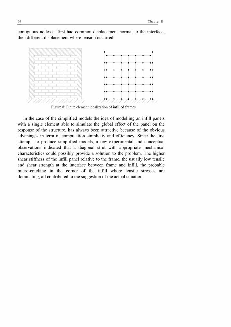
Chapter II
60
contiguous nodes at first had common displacement normal to the interface, then different displacement where tension occurred.
Figure 8: Finite element idealization of infilled frames. In the case of the simplified models the idea of modelling an infill panels
with a single element able to simulate the global effect of the panel on the response of the structure, has always been attractive because of the obvious advantages in term of computation simplicity and efficiency. Since the first attempts to produce simplified models, a few experimental and conceptual observations indicated that a diagonal strut with appropriate mechanical characteristics could possibly provide a solution to the problem. The higher shear stiffness of the infill panel relative to the frame, the usually low tensile and shear strength at the interface between frame and infill, the probable micro-cracking in the corner of the infill where tensile stresses are dominating, all contributed to the suggestion of the actual situation.
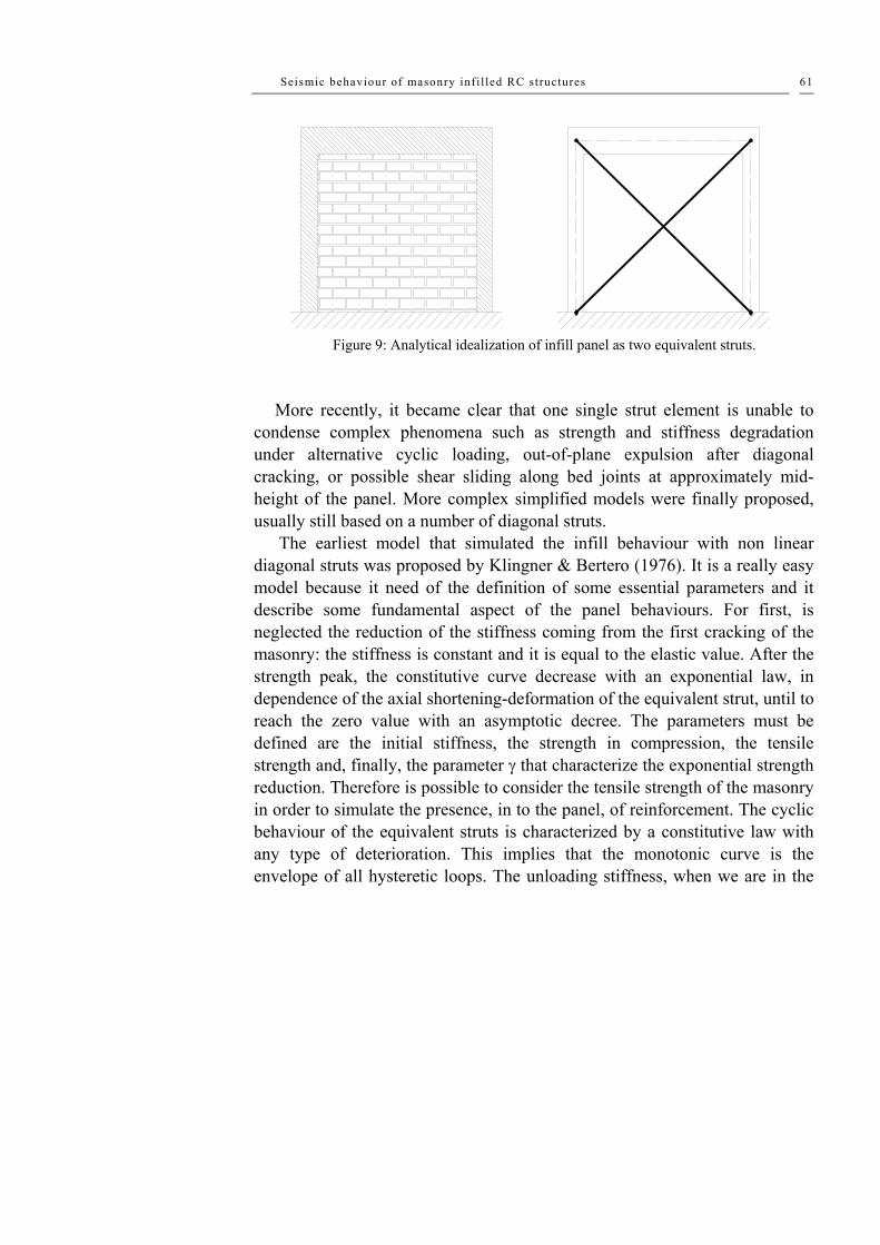
Seismic behaviour of masonry infi l led RC structures 61
Figure 9: Analytical idealization of infill panel as two equivalent struts.
More recently, it became clear that one single strut element is unable to
condense complex phenomena such as strength and stiffness degradation under alternative cyclic loading, out-of-plane expulsion after diagonal cracking, or possible shear sliding along bed joints at approximately mid-height of the panel. More complex simplified models were finally proposed, usually still based on a number of diagonal struts.
The earliest model that simulated the infill behaviour with non linear diagonal struts was proposed by Klingner & Bertero (1976). It is a really easy model because it need of the definition of some essential parameters and it describe some fundamental aspect of the panel behaviours. For first, is neglected the reduction of the stiffness coming from the first cracking of the masonry: the stiffness is constant and it is equal to the elastic value. After the strength peak, the constitutive curve decrease with an exponential law, in dependence of the axial shortening-deformation of the equivalent strut, until to reach the zero value with an asymptotic decree. The parameters must be defined are the initial stiffness, the strength in compression, the tensile strength and, finally, the parameter γ that characterize the exponential strength reduction. Therefore is possible to consider the tensile strength of the masonry in order to simulate the presence, in to the panel, of reinforcement. The cyclic behaviour of the equivalent struts is characterized by a constitutive law with any type of deterioration. This implies that the monotonic curve is the envelope of all hysteretic loops. The unloading stiffness, when we are in the

Chapter II
62
positive quadrant, is the same of the loading one, but when we are in the negative quadrant the stiffness is equal to zero.
Strut axial force (tension)
Strut axial deformation (tension)
Tension curve
Strength envelope curveElastic loading curve
A
B
C
F
D'
E'H'
B'
E
DHGC'
Figure 10: Klingner & Bertero mechanical behaviour of strut. Polyakov (1956) studied the shear and normal stresses at the centre of an
infill panel, combining a variational method with the Airy function. Comparing experimental and numerical result, He proposed a method for the analytical estimation of the force needed to produce diagonal cracking.
Holmes (1961) gave a first indication fir the definition of an equivalent diagonal strut. He arbitrarily assumed that its width was the third part of the diagonal between the two compressed corners.
Stafford Smith (1966, 1968) and Smith and Carter (1969) observed that a diagonal strut acting directly between the two compressed corners of the frame was an oversimplification, since the finite contact length between infill panel and frame members may significantly influence either the width of the equivalent strut or the behaviour of the frame itself. They suggested that the contact length depends on the relative stiffness of infill and frame. The width of the equivalent diagonal strut was then calculated assuming a triangular distribution of the contact forces on each contact length. For the purpose of

Seismic behaviour of masonry infi l led RC structures 63
evaluating the elastic stiffness of the infilled frames, their proposal proved to be quite effective and is still applied with success.
Based on the contact length, alternative methods for the evaluation of the equivalent width have been given by Mainstone (1971) and Kadir (1974).
Liauw & Lee (1977) used a modified equivalent strut model to simulate the effective stiffness and the ultimate strength of infilled frames with openings. An elastic-perfectly plastic behaviour of materials was assumed, and only monotonic static loading was addressed.
Thiruvengadam (1985) proposed to simulate the effect of an infill panel using several diagonal struts in each direction, allowing the simulation of a finite compressed length on the frame elements. In this way it becomes easier also take into account the presence of openings. The objective was a realistic evaluation of the natural frequencies and modes of vibration, purposes for which the non-linear phenomena do not play an important role. Results were compared with the vibration frequencies obtained using the single diagonal model as proposed by Stafford Smith, with the predictions of finite element analyses and with some experimental results.
Doudomis & Mitsopoulou (1986) introduced a new criteria to take into account the strength deterioration due to cyclic loading in their equivalent diagonal struts model. Firstly, they assumed that the infill is not firmly connected to the frame at the beginning, therefore, in the model the strut remain inactive up to a certain level of deformation of the surrounding frame, such as to close the initial gap at the interface due o shrinkage. Secondly, the boundary conditions at the interface are unilateral, which means that no tensile stresses may develop at the contact area.
Syrmakezis & Vratsanou (1986) suggested a distribution of multiple equivalent diagonal struts to give a better estimation of the compressed zone, both in the infill panel and in the frame members. It was stressed that different compressed length have a significant effect on the bending moment distribution in the frame members.
D’Asdia et al. (1990) made some comparison between numerical studies with the finite element method and analyses with the equivalent diagonal strut model. They used micro-models to evaluate the influence of various parameters on the global response of infilled frames, and macro-models to compute the seismic response of entire buildings, taking into account non-
Chapter II
64
linear phenomena under cyclic actions. The main purpose of the parametric studies was to investigate the interface condition and, in particular, the imperfect adhesion between frame and infill, by considering different values of the friction coefficient. They assumed elastic-perfectly plastic behaviour for all reinforced concrete elements and an elastic-brittle behaviour for the infill walls. The interface was modelled with link elements. Here they assumed different relationship under compression, tension and shear; bilinear elastic, elastic-brittle and elastic-perfectly plastic respectively. Finally, the constitutive relationship for the struts was based not only on the geometrical dimension and the material characteristic, but also on the friction coefficient in the contact area.
Chrysostomou (1991) and Chrysostomou et al. (1992) simulated the response of infilled frames under earthquake loading, taking into account stiffness and strength degradation of the infills. He proposed to model each infill panel with three struts in each diagonal direction. The distance of the exterior struts is defined by the fraction of the length or the height of a panel and is associated with the location where a plastic hinge forms in a beam or a column. At any point of the analysis only three of the six struts are active. The force-displacement relationship of the infill walls are defined by a hysteretic model. The proposed model was implemented in a three-dimensional non-linear analysis programme and used and tested on simple and multi-storey multi-bay infilled frames, to study the effects of infill walls on the non-linear dynamic behaviour of infilled frames.
In Panagiotakos & Fardis (1991) is proposed a model for the infill wall by an elaboration of the model proposed by Tassios. The constitutive curve is composed by different lines. In to the quadrant of the compression there are four segment that corresponding respectively to the initial shear-behaviour of the non-cracked panel, to the equivalent rod of the cracked panel, to the unstable behaviour of the infill walls and, finally, to the final state after the complete collapse of the infill with a constant residual strength. In the region of the tensile any type of strength is neglected. The Authors suggest a value for the initial stiffness equal to the stiffness of the non-cracked walls and it is equal to Gwtwlw/hw; the secant stiffness from the cracking point until the maximum strength correspond to the stiffness of an equivalent diagonal with the elastic modulus equal to the modulus of the wall in the diagonal direction;

Seismic behaviour of masonry infi l led RC structures 65
the negative stiffness of the unstable line is equal to 0.5% of the initial stiffness; the cracking strength can be assumed identical to the shear strength (fwstwlw) obtained from the diagonal compression test; the maximum strength is 1.3 times the cracking one and, finally, the residual strength can be assumed equal to 5-10% of the maximum load.
As mentioned previously, an infill panel tends to separate from its bounding frame at a relatively low lateral load level. After this, its contact with the bounding frame is limited to the two opposite compression corners, forming a resistance mechanism similar to that of a diagonal strut. For this reason, the in-plane behaviour of an infilled frame is distinctly different from that of a shear wall or shear beam. Fiorato et al. have proposed the use of a shear beam model to estimate the initial stiffness of an infilled frame. They have found good correlations with their experimental results. Nevertheless, it must be pointed out that they have compared it with the initial stiffness of their infilled frames that was developed within a very low load level (10–30% of the ultimate load). This may not be reflective of the overall behaviour of an infilled frame before peak. Mehrabi et al. have defined a secant stiffness that is more reflective of the average behaviour of an infilled frame before reaching the ultimate load. It is defined as the slope of a line connecting the extreme points of a displacement cycle in which the peak load is about 50% of the maximum lateral resistance. They have compared the secant stiffness of the infilled frames they tested with the shear beam model. They have found that for most frames with weak infills, the shear beam model provides a very close correlation. Nevertheless, for frames with strong infills, the shear beam model tends to overestimate the secant stiffness by more than two-fold. The latter indicates the separation of the infills from the bounding frames at a low load level. In their comparative study of different analytical models, R.D. Thomas and R.E. Klingner have found that the shear beam model can overestimate the lateral stiffness of an infilled frame by as much as 13-fold. Nevertheless, they do not mention how the lateral stiffness is defined.
Because of frame–infill interaction, the load resisting mechanism of an infilled frame can be very different from that of a bare frame or a wall panel alone. In most cases, the lateral load resistance cannot be considered as a simple sum of the two components. The simplest and most common approach to model this interaction is the use of an equivalent diagonal strut concept.

Chapter II
66
Holmes has proposed that the effective width of an equivalent strut depends primarily on the thickness and the aspect ratio of the infill. Stafford Smith has used an elastic theory to show that this width should be a function of the stiffness of the infill with respect to that of the bounding frame. By analogy to a beam on elastic foundation, Stafford Smith has defined a dimensionless relative stiffness parameter as follows to determine the degree of frame–infill interaction and thereby, the effective width of the strut. He has developed a theoretical relation between the relative stiffness parameter, and the contact length between the infill and the frame. He has then used a set of theoretical curves to relate the contact length and the aspect ratio of the infill to the effective width of the diagonal strut. Nevertheless, Stafford Smith has found that his theory tends to overestimate the effective width of an equivalent strut, based on his experimental results. He has subsequently developed a set of empirical curves that relate the stiffness parameter to the effective width of an equivalent strut. These curves have shown better correlations with experimental data than his theoretical results. According to this model, the larger the value of l, the smaller will be width of the equivalent strut. As a final note, Stafford Smith’s strut model is based on his experimental observations of steel frames infilled with mortar, which can be considered homogeneous and isotropic before cracking. He has not validated it with masonry infills, which are anisotropic and have inherent planes of weakness introduced by mortar joints.
Mainstone & Weeks have proposed an empirical relation between the effective width of an equivalent strut and Stafford Smith’s stiffness parameter for masonry infills. This relation results in a lower value of the effective width than that given by Stafford Smith’s model. The accuracy of the above models in predicting the lateral stiffness of masonry-infilled frames varies significantly from one study to another. Mehrabi et al. and R.D. Thomas & R.E. Klingner have found that Mainstone & Weeks’ model significantly underestimates the lateral stiffness of the infilled frames considered. With Stafford Smith’s model, using the bending stiffness of uncracked reinforced concrete sections, Mehrabi et al. have found that the lateral stiffness of their infilled frames is consistently underestimated by a factor of two. The frames had different frame-to-panel stiffness ratios and their measured secant

Seismic behaviour of masonry infi l led RC structures 67
stiffness varies from 430 to 1470 kips/in. The discrepancy would be more significant if the cracked section stiffness were used.
R.D. Thomas & R.E. Klingner and Bashandy et al.[17] have found that Holmes’ model and Stafford Smith’s model result in very similar stiffness values for the frames considered. Both models provide very close correlations to the stiffness values obtained by experiments and finite element models. Angel et al. have found that Stafford Smith’s model tends to over-predict the experimentally measured stiffness by a factor of two. Holmes’ model provides similar results. This could be partly related to the way the lateral stiffness is defined. They have used the lateral stiffness measured at the cracking of the infills for comparison.
In view of the widely different results from the aforementioned studies, no definitive conclusions can be reached. However, Stafford Smith’s model seems to show some consistency within each study, whether it tends to over- or under-estimate the lateral stiffness. This points to a couple of issues that need to be resolved in future studies. One is a proper and consistent definition of the initial lateral stiffness of an infilled frame that is reflective of the overall behaviour before major damage, and the other is thevalue of the modulus of elasticity of masonry that should be used in Stafford Smith’s model. Values obtained from masonry prism tests might not be most appropriate in view of the highly anisotropic behaviour of unreinforced masonry. Strut models have been used to evaluate the strength as well as the stiffness of infilled frames. Even though some limited success has been achieved, the use of an equivalent strut model to calculate the strength of an infilled frame is rather inadequate for a number of reasons. Most importantly, an infilled frame has a number of possible failure modes caused by the frame–infill interaction, and a compression strut type failure is just one of many possibilities. It is evident that the use of a diagonal strut is not able to duplicate a number of the failure mechanisms, such as the short-column phenomenon and the sliding bed-joint failure of a masonry infill. Furthermore, the effective width proposed by Stafford Smith is based on an elastic theory and may not be adequate for the ultimate limit state. The contact length between the infill and the frame will change as the infill approaches its ultimate resistance.
A strut model that is based on a limit analysis approach has been proposed by Saneinejad & Hobbs, and this model has been extended by Madan et al. to

Chapter II
68
incorporate a hysteretic behaviour for cyclic load analysis. Both models are developed for the analysis of multi-storey steel frames. In these models, the crushing of the infill is assumed to be the predominant failure mode. Based on their experimental observations, Zarnic & Gostic have proposed a hysteretic strut model in which the ultimate strength is governed by the shear capacity of the masonry infill. The model, however, has a number of empirical parameters that need to be calibrated.
In-plane strength predictions of infilled frames are a complex, statically indeterminate problem. The strength of a composite-infilled frame system is not simply the summation of the infill properties plus those of the frame. Great efforts have been invested, both analytically and experimentally, to better understand and estimate the composite behavior of masonry-infilled frames. Polyakov (1960) (work dating back to the early 1950s), Stafford-Smith (1962, 1966, 1969), Main-stone (1971), Klingner and Bertero (1976, 1978), to mention just a few, formed the basis for understanding and predicting infilled frame in-plane behavior. Their experimental testing of infilled frames under lateral loads resulted in specimen deformation shapes similar to the one illustrated in following Figure 11.
Figure 11: Specimen deformation shape.
During testing of the specimens, diagonal cracks developed in the center of
the panel, and gaps formed between the frame and the infill in the nonloaded diago-nal corners of the specimens, while full contact was observed in the two loaded diagonal corners. This behavior, initially observed by Polyakov, lead to a simplification in infilled frame analysis by replacing the masonry infill with an equivalent compressive masonry strut.

Seismic behaviour of masonry infi l led RC structures 69
The equivalent masonry strut of width, a, with same net thickness and mechanical properties (such as the modulus of elasticity Em) as the infill itself, is as-sumed to be pinned at both ends to the confining frame.
The evaluation of the equivalent width, a, varies from one reference to the other. The most simplistic approaches presented by Paulay and Priestley (1992) and Angel et al. (1994) have assumed constant values for the strut width, a, between 12.5 to 25 percent of the diagonal dimension of the infill, with no regard for any infill or frame properties. Stafford-Smith and Carter (1969), Mainstone (1971), and others, derived complex expressions to estimate the equivalent strut width, a, that consider parameters like the length of contact between the column/beam and the infill, as well as the relative stiffness of the infill to the frame.
The expressions used in this report have been adopted from Mainstone (1971) and Stafford-Smith and Carter (1969) for their consistently accurate predictions of infilled frame in-plane behavior when compared with experimental results (Mainstone 1971; Stafford-Smith and Carter 1969; Klingner and Bertero 1978; and Al-Chaar 1998).
The masonry infill panel will be represented by an equivalent diagonal strut of width, a, and net thickness teff as shown in Figure 12.
Figure 12: Equivalent diagonal strut.
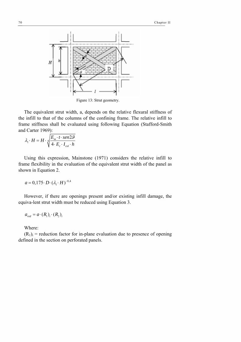
Chapter II
70
Figure 13: Strut geometry.
The equivalent strut width, a, depends on the relative flexural stiffness of
the infill to that of the columns of the confining frame. The relative infill to frame stiffness shall be evaluated using following Equation (Stafford-Smith and Carter 1969):
412
4m
c col
E t senH HE I h
ϑλ ⋅ ⋅⋅ = ⋅
⋅ ⋅ ⋅
Using this expression, Mainstone (1971) considers the relative infill to
frame flexibility in the evaluation of the equivalent strut width of the panel as shown in Equation 2.
0,4
10,175 ( )a D Hλ −= ⋅ ⋅ ⋅ However, if there are openings present and/or existing infill damage, the
equiva-lent strut width must be reduced using Equation 3.
1 2( ) ( )red i ia a R R= ⋅ ⋅ Where: (R1)i = reduction factor for in-plane evaluation due to presence of opening
defined in the section on perforated panels.

Seismic behaviour of masonry infi l led RC structures 71
(R2)i = reduction factor for in-plane evaluation due to existing infill damage de-fined in the corresponding section on page.
Although the expression for equivalent strut width given by Equation 2 was derived to represent the elastic stiffness of an infill panel, this document will extend its use to determine the ultimate capacity of infilled structures. The strut will be assigned strength parameters consistent with the properties of the infill it represents. A nonlinear static procedure, commonly referred to as a pushover analysis, will be used to determine the capacity of the infilled structure.
Eccentricity of Equivalent Strut The equivalent masonry strut is to be connected to the frame members as
depicted in Figure 14. The infill forces are assumed to be mainly resisted by the columns, and the struts are placed accordingly. The strut should be pin-connected to the column at a distance lcolumn from the face of the beam. This distance is defined in previous two Equations and is calculated using the strut width, a, without any reduction factors.
cos( )colcol
alϑ
= cos( )tan( ) colcol
ah
lθϑ
−=
Using this convention, the strut force is applied directly to the column at
the edge of its equivalent strut width, a. This concept is illustrated in Figure 4.
Figure 14: Placement of the strut.

Chapter II
72
In the case of a perforated masonry panel, the equivalent strut is assumed to act in the same manner as for the fully infilled frame. Therefore, the eccentric strut should be placed at a distance lcolumn from the face of the beam as shown in Figure 15. The equivalent strut width, a, shall be multiplied, however, by a reduction factor to account for the loss in strength due to the opening. The reduction factor, (R1)i, is calculated using the seguent Equation.
2
1( ) 0,6 1,6 1open openi
panel panel
A AR
A A⎛ ⎞ ⎛ ⎞
= − +⎜ ⎟ ⎜ ⎟⎜ ⎟ ⎜ ⎟⎝ ⎠ ⎝ ⎠
Where: Aopen = area of the openings Apanel = area of the infill panel
Figure 15: Perforated panel.
Note that reducing the strut width to account for an opening does not
necessarily represent the stress distributions likely to occur. This method is a simplification in order to compute the global structural capacity. Local effects due to an opening should be considered by either modeling the perforated panel with finite elements or using struts to accurately represent possible stress fields as shown in Figure 16.

Seismic behaviour of masonry infi l led RC structures 73
Figure 16: Possible strut placement for perforated panels.
The eccentric equivalent strut used to model the masonry infill is pin-
connected to the frame elements so that no moment transfer occurs. The stiffness of the strut will be governed by the modulus of elasticity of the masonry material (Em) and the cross-sectional area (a x teff). The strength of the strut is determined by calculating the load required to reach masonry infill crushing strength (Rcr) and the load required to reach the masonry infill shear strength (Rshear). The component of these forces in the direction of the equivalent strut will be used to assign the strut a “compressive” strength. This strength is defined as Rstrut and governs the strength of the plastic hinge in the strut.
Rstrutt = min {Rc , Rshear/cosθstrutt}
2tan col
colh l
lθ −
=
Where:
θstrut = the angle of the eccentric strut with respect to the horizontal.

Chapter II
74
Figure 17: Geometry of the strut.
The equivalent strut is assumed to deflect to nonlinear drifts as Figure 18
shows.
Figure 18: Load deformation behavior.
The parameter d, which represents the nonlinear lateral drift associated
with the infilled panel, is defined in Table 7-7 of FEMA 273. The masonry infill crushing strength corresponds to the compressive load
that the equivalent masonry strut can carry before the masonry is crushed (Rcr). The applied load that corresponds to the crushing strength of the infill is evaluated using gived Equation.

Seismic behaviour of masonry infi l led RC structures 75
'meffredcr ftaR ⋅⋅=
Where: f'm = compressive strength of the masonry teff = net thickness of the masonry panel The capacity of masonry to shear forces is provided by the combination of
two different mechanisms: the bond shear strength and the friction between the ma-sonry and the mortar. The concept of the bond shear strength is illustrated in Figure 19, where a typical stair-stepped shear crack is approximated by a single shear crack through a bed joint. This simplification is valid because the vertical component of the stair-stepped crack will be in tension, and its contribution to the shear strength should be neglected. Therefore, the horizontal lateral load required to reach the infill shear strength is calculated by following Equation.
'
1 2( ) ( )shear n v i iR A f R R= ⋅ ⋅ ⋅ Where: AP = net cross sectional mortar/grouted area of infill panel along its length f'v = masonry shear strength
Although vertical loads on infills may not be accurately estimated, 20 per-cent of the normal stress may be assumed to be resisted by the infill and in-cluded in the friction component of the resisting mechanism.
Figure 19: Shear failure of masonry.
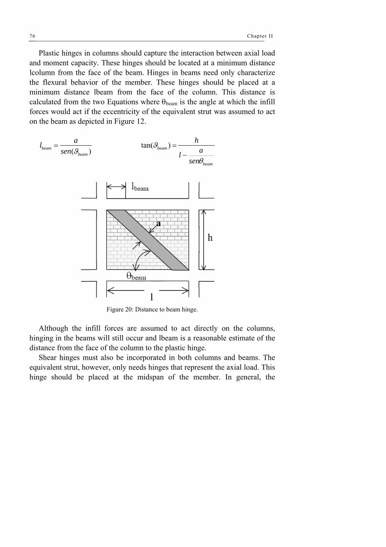
Chapter II
76
Plastic hinges in columns should capture the interaction between axial load and moment capacity. These hinges should be located at a minimum distance lcolumn from the face of the beam. Hinges in beams need only characterize the flexural behavior of the member. These hinges should be placed at a minimum distance lbeam from the face of the column. This distance is calculated from the two Equations where θbeam is the angle at which the infill forces would act if the eccentricity of the equivalent strut was assumed to act on the beam as depicted in Figure 12.
( )beambeam
alsen ϑ
= tan( )beam
beam
hal
sen
ϑ
θ
=−
Figure 20: Distance to beam hinge.
Although the infill forces are assumed to act directly on the columns,
hinging in the beams will still occur and lbeam is a reasonable estimate of the distance from the face of the column to the plastic hinge.
Shear hinges must also be incorporated in both columns and beams. The equivalent strut, however, only needs hinges that represent the axial load. This hinge should be placed at the midspan of the member. In general, the

Seismic behaviour of masonry infi l led RC structures 77
minimum number and type of plastic hinges needed to capture the inelastic actions of an infilled frame are depicted in Figure 21.
Figure 21: Plastic hinge placement.
Although lateral loading generally leads to hinge formation near the end of
a member, inelastic deformation may occur at other locations, especially when large gravity loads are present. Therefore, the possibility of hinging near midspan must not be overlooked. In addition, the engineer is allowed to place hinges differently if the placement is justified and good engineering judgment is used.
The frame elements surrounding a panel containing an equivalent strut in the mathematical model will be too flexible. This is because of the lack of confine-ment produced by the strut that would have been provided had the infill been modeled with finite elements. To counteract this effect, it is recommended that REOs be placed on the frame members surrounding an infilled panel. For beams surrounding infilled panels, REOs should be used from the beam/column joint to a distance of lbeam from the face of the column. For columns surrounding infilled panels, REOs should be placed from the beam/column joint to a distance of lcolumn from the face of the

Chapter II
78
beam. These distances also correspond to the locations of the beam and column plastic hinges. The beam or column is therefore assumed to be rigid up to the point of the plastic hinge. Figure 14 shows the placement of REOs (shown in black) for an infilled frame.
Figure 22: Rigid end offset placement.
The mathematical model should be subjected to monotonically increasing
lateral loads until the maximum displacement of the design earthquake is reached or a failure mechanism forms. The target displacement should be calculated following the procedure in Section 3.3.3.3 of FEMA 273. Gravity loads should be applied as initial conditions prior to the earthquake loadings. The load combina-tions that should be used are given by Equations 3-2 and 3-3 in FEMA 273.
Lateral loads should be applied in a manner that approximates the inertia forces in the design earthquake. It is recommended that a minimum of two different inertia force distributions be used in order to capture the worst case design forces. The recommended inertia force distributions are given in Section 3.3.3.2 of FEMA 273.
A masonry infill panel can be modeled by replacing the panel by a system of two diagonal masonry compression struts, A. Madan (1997). By ignoring the tensile strength of the infill masonry, the combination of both compression components provides a lateral load resisting mechanism for the opposite lateral directions of loading. Figure 23 illustrates the analytical model as well as a strength envelope for masonry infill walls.

Seismic behaviour of masonry infi l led RC structures 79
Figure 23: Strength envelope for conventional masonry infill walls and the analytical model
The main factors of the envelope model, in Figure 23, are shear strengths at the assumed yielding point, Vy , at the maximum point Vm, and the post-peak residual shear strength, Vp, and their corresponding displacements, Uy, Um, and Up, respectively. In the figure, α is the ratio of stiffness after the yielding to that of the initial stiffness. In order to obtain the main parameters of the envelope curve, maximum lateral strength, Vm, should be estimated considering the two critical failure modes, sliding shear and compression failures. The other factors can be approximated based on the following equations. The maximum displacement at the maximum lateral force is estimated by equation (A. Mandan et al, 1997):
'm m
mdU
cosε ⋅
=ϑ
where, m ε′ is the masonry compression strain at the maximum
compression stress, in here 0.0018 = ε′m , and dm is the diagonal strut length. A maximum drift limitation of 0.8% is applied for Um/hm ratio, which is implied from experimental results, Mehrabi et al. (1996) and Chen Y. H.

Chapter II
80
(2003). The initial stiffness K0 can be estimated by the following equation, Mandan et al. (1997):
K0=2(Vm/Um) The lateral yielding force Vy, and displacement Uy may be calculated from
the geometry in Figure 23:
m 0 my
V K UV1
−α ⋅ ⋅=
−α
y
y0
VU
K=
In here, the value of α is assumed equal to 0.2. Up and Vp can be defined based on the previews experimental results. The
average value of drifts ratio at the 80% post-peak point, defined as a point on the envelope curve, in Figure 23, with shear level 80% of the maximum shear strength, is about 1.5% for concrete block infill walls, Mehrabi et al. (1996). It is assumed as (3/4)1.5%=1%, for solid bricks walls. The Vp and Up should be determined considering that the line connecting the peak of the envelope and the point (Vp, Up) passes through the 80% postpeak point. Therefore assuming;
Vp=0.3 Vm It may lead to: Up=3.5(0.01hm-Um) Here is an example of one-bay frame with an infill masonry wall. In order
to show the applicability of the horizontal spring model instead of a diagonal spring model, the infilled frame is analyzed with the both models. Pushover analyses were employed for the two infilled frame models in Figure 25.
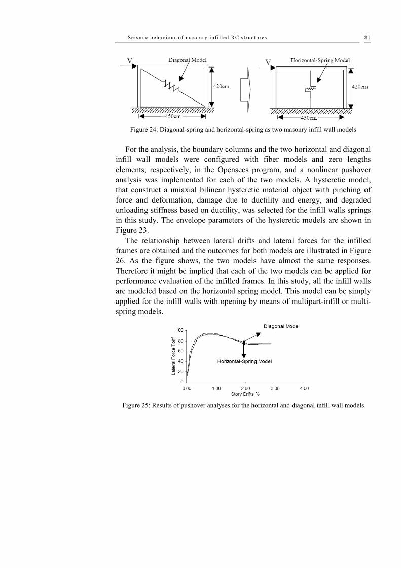
Seismic behaviour of masonry infi l led RC structures 81
Figure 24: Diagonal-spring and horizontal-spring as two masonry infill wall models
For the analysis, the boundary columns and the two horizontal and diagonal infill wall models were configured with fiber models and zero lengths elements, respectively, in the Opensees program, and a nonlinear pushover analysis was implemented for each of the two models. A hysteretic model, that construct a uniaxial bilinear hysteretic material object with pinching of force and deformation, damage due to ductility and energy, and degraded unloading stiffness based on ductility, was selected for the infill walls springs in this study. The envelope parameters of the hysteretic models are shown in Figure 23.
The relationship between lateral drifts and lateral forces for the infilled frames are obtained and the outcomes for both models are illustrated in Figure 26. As the figure shows, the two models have almost the same responses. Therefore it might be implied that each of the two models can be applied for performance evaluation of the infilled frames. In this study, all the infill walls are modeled based on the horizontal spring model. This model can be simply applied for the infill walls with opening by means of multipart-infill or multi-spring models.
Figure 25: Results of pushover analyses for the horizontal and diagonal infill wall models

Chapter II
82
Different infill wall models are developed for different opening types.
Figures 26-a to 26-g illustrate the different spring models for infill walls with windows and doors openings as well as infill complex RC-masonry walls. Springs for infill walls with different stiffness in the vertical direction, such as those in Figures 26-a to 26-f, are constrained to the corresponding nodes along the column lengths. This can be implemented by decomposing the column into two or three sub-elements, depending on the number of infill walls sub-elements in vertical direction. For example, boundary columns of the infill walls in Figure 26-a are divided into three column sub-elements by introducing two extra nodes along the columns. The horizontal springs are constrained to the corresponding nodes on the column sub-elements. The horizontal lines between the extra nodes illustrate the constraining paths without any other effect on the structural stiffness. The horizontal springs may be constrained to the corresponding nodes on the columns for compression only, in case of assuming zero tensional strength at the interface nodes.
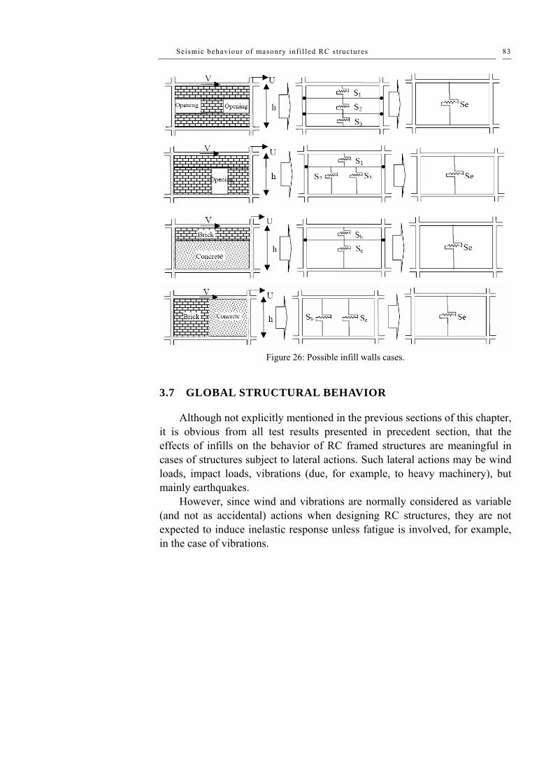
Seismic behaviour of masonry infi l led RC structures 83
Figure 26: Possible infill walls cases.
3.7 GLOBAL STRUCTURAL BEHAVIOR
Although not explicitly mentioned in the previous sections of this chapter, it is obvious from all test results presented in precedent section, that the effects of infills on the behavior of RC framed structures are meaningful in cases of structures subject to lateral actions. Such lateral actions may be wind loads, impact loads, vibrations (due, for example, to heavy machinery), but mainly earthquakes.
However, since wind and vibrations are normally considered as variable (and not as accidental) actions when designing RC structures, they are not expected to induce inelastic response unless fatigue is involved, for example, in the case of vibrations.

Chapter II
84
Indeed, impact loads which are likely to induce inelastic response at least to part of the structure on which they act, are not considered in the literature dealing with the effect of infills.
Thus, it seems that the only case for which one may try to describe, be it qualitatively, the effect of infills on the behavior of the structure as a whole, is that of RC frame structures subject to earthquakes. Such an attempt is presented in what follows, while some possible design measures are also suggested.
It has already been clarified that the presence of infills modifies the basic frame behavior, stiffening the frame and creating new potential failure mechanisms. A very rough subdivision of the possible effects of infills could be described as follows:
a) The presence of infills does not affect significantly the structural response. This can be the case if the infills are very light and flexible, or completely isolated from the reinforced concrete frame. From a seismic point of view, very brittle infills too would not significantly affect the frame response, provided that a total failure of the infills is expected even for moderate ground acceleration. But this case would not comply with any sensible design for a serviceability or damage limit state.
b) The infills do affect the frame response, but they are expected to remain elastic under the design actions. In this case simpler models can be used for the infill panels. The response could be completely linear elastic, or some non-linear phenomena could take place in columns and beams. Generally a possible shear wall behavior should be considered, with columns acting as tension or compression boundary members and the infill action, as a connecting shear element.
c) The infills affect the frame response, and they are expected to suffer significant damage under the design actions. In this case more sophisticated models should be used, and the high probability of the formation of a soft storey has to be recognized and taken into account.
The probability of a high torsional response has to be carefully examined; such a response has to be expected if the infills stiffen different parts of the structure in different ways, attracting a disproportionate level of force and creating a significant distance between centre of rigidity and centre of mass.

Seismic behaviour of masonry infi l led RC structures 85
Finally, possible local influence on brittle shear failure of some frame members, whose shear span ratio could be reduced by the presence of infills, should be recognized and generally avoided.
The experimental results previously presented illustrate the beneficial effect of infills on the lateral resistance of RC frames. It 1s also apparent, however, that the results are very scattered and that the lateral resistance of the infilled structure is very much dependent on the strength of infills, on the conditions of connections between infill and frame, and on the relative stiffness of infill and frame. In any event, there is a significant extra resistance offered by the non-structural walls. In some experimental tests is shown that even after several cycles at angular distortions as large as 2-3%, the lateral resistance of the (heavily damaged) infilled structure can remain about 50% higher than the resistance of the bare structure.
Nevertheless, three considerations can significantly reduce the impression of the higher safety aspect given above. Most of the experimental tests available having been performed on single-storey specimens, the potential for damage concentration and, therefore, soft-storey-type failure mechanisms are not explored. The potential for an out-of-plane expulsion after some damage from in-plane actions has not been explored, while it is likely to govern the strength deterioration of the panel. Due to the previous considerations, the higher elastic strength can correspond to a much lower global ductility, or, from a design point of view, to a value of the force reduction factor close to 1 (i.e. an elastic design).
As shown by all available test results, the addition of infill walls to frames leads to a drastic increase of lateral stiffness of the structure. In fact, one may expect an initial lateral stiffness of the infilled frame 4 to 20 times that of the respective bare frame. A similar effect is expected in the structure as a whole, depending however on both the total number of infill walls in both directions and the thickness of infills. Obviously, this increase of the initial lateral stiffness would result in a decreased natural period of vibration of the infilled structure, when compared to the value of the respective bare structure. This decrease of period seems to be independent of the location of infills within the structure, as the tests by Shahinian et al. (1982) have shown. Due to the decreased natural period of the infilled structure, the expected seismic action is also affected, depending on the characteristics of the earthquakes
Chapter II
86
which may occur. It should be noted that the above remark holds true for the initial elastic stage of the behavior of the structure. In fact, since earthquakes inducing inelastic behavior are considered, as soon as damages to infills and/or to RC elements occur, the lateral stiffness of the structure decreases.
Therefore, the natural period of the structure increases. Tamura et al. (1968) have measured at the moment of failure of their modes, a natural period of vibration seven times the initial one, while Shahinian et al. (1982) measured a natural period at failure 2.3 times higher than the initial one.
The non-uniform distribution of infill walls along the height of the structure does affect the vertical height of the bearing structure. This is a very well-known issue, especially in the extreme case of a soft ground or intermediate storey. As a result of the non-uniform in-elevation distribution of infills, the vertical RC elements of the soft storey are subject to higher inter-storey drifts.
Therefore, the RC elements of the soft storey should either be designed or reinforced so that they are able to exhibit higher ductility than the RC elements of the remaining storey, or they should be designed for higher base shear (or for locally lower behavior factor).
It should be noted, however, that the vertical irregularity of a structure is subject to continuous alterations during an earthquake, which modifies the stiffness and the resistance of the various elements of the structure. For this reason it has been suggested (Priestley and Calvi, 1991) that a possible formation of a soft storey should be considered anyway, if an infilled frame is designed with a force reduction factor larger than unity, and the RC frames be designed accordingly.
When a frame is laterally loaded, a separation between frame elements and infill wall occurs at early loading stages. From this separation stage on, only part of the infill (the region around the compressed diagonal) is stressed, while the remaining part of the infill remains free from stresses. Thus additional shear forces are expected to act on columns and beams adjacent to an infill.
Nevertheless, the total shear acting on RC elements may not be calculated as the sum of the action-effect on the bare structure and the additional shear due to frame-infill interaction. In fact, the presence of infills leads in general to decreased action-effects on the RC elements, since a

Seismic behaviour of masonry infi l led RC structures 87
considerable part of the seismic forces is resisted by the so-called non-structural infill walls. Thus, the shear force due to frame-infill interaction should be added to that decreased shear force on the RC elements.
In some cases, however (e.g. in-plan or in-elevation irregularities), the shear forces acting on RC elements may be considerably higher than those obtained from the analysis of the bare structure. This might lead to a premature shear (hence, brittle) failure of some RC elements. In the case of infills expected to remain in the elastic range, some global inelastic shear wall behavior may take place, with columns acting as tension or compression boundary elements and the infill acting as a connecting shear element. The variation in the column vertical stress due to the presence of infills is, in this case, evident and can be analytically computed.
Aspects of three-dimensional behavior
The non-uniform distribution of infill wails in-plan, may lead to enhanced torsional effects on several RC elements. These effects are not taken into account in normal design.
A possible influence of masonry infill on the global behavior of a structure can be illustrated by reference to Fig. 5, which represents a floor plan of a symmetrical two-way frame on a comer site. The frames on the two sides forming a boundary with other buildings have been infilled. As a consequence, the building stiffness as a whole is increased, frames 4 and d attract a disproportionate level of seismic force, being stiffer than the other frames, and a high torsional response should be expected, because the centre of rigidity R is moved towards the stiffer infilled frames.
It has to be noted that for such a structure equilibrium is possible only with very large rotations, corresponding to large displacements in the outer bare frames. If three sides should have been filled a potentially better behavior could have been obtained, because of the resisting couple offered by the two parallel infilled frames.
The stiffness of floors has an obvious and fundamental influence on the three-dimensional response of infilled frames: in the extreme case of a very flexible floor the seismic forces should be distributed according to the tributary area principle, regardless of the stiffness of different plane frames. In

Chapter II
88
modem constructions, however, floors are commonly assumed as infinitely rigid, with the consequent enhancement of torsional response. This assumption is not adequate in case of floor plane geometry requiring large shear redistribution through the slab, or slender plan configuration. The increased stiffness of infilled frames with respect to bare frames may contribute to make more realistic the assumption of deformable floors.
The conclusions drawn in the previous section on variation of actions in frame members due to frame-infill interaction are generally applicable to the three-dimensional case, with more complex results. A significant biaxial bending in columns may be one of the most dangerous consequences, and should be carefully considered.
Implications of design principles on behavior and modeling
Because of the significant effect of infill walls on the seismic behavior of frame structures discussed in this chapter, a drastic modification of the design of RC structures could be proposed: infills might be considered as structural, taken into account in analysis and dimensioned accordingly. There are, however, several arguments against such a handling of the problem.
Infilling and partitioning of RC buildings using non-engineered, rather poor quality masonry walls is an everyday practice (generally accepted in earthquake prone areas because of their low cost). The change of non-engineered, non-structural infill walls into engineered, structural walls, would cause a dramatic increase in the cost of infill walls (including an increase of the design cost, because of its higher degree of sophistication and complexity), and would require a higher level of quality control in construction of infills. Besides, even slight modifications of the layout of infill walls would not be allowed, unless appropriately checked by a structural engineer.
In relation to this, one should mention that this significant modification both in design and construction philosophy is not justified by the experience of past earthquakes. In fact, it seems that the presence of non-engineered infill walls is often positive.
At the other extreme of the spectrum there is the solution of separating the infill walls from the surrounding frame, thus leaving them to behave independently from the bearing structure.

Seismic behaviour of masonry infi l led RC structures 89
However, in this case too, significant changes in everyday construction practice would be necessary, insulation problems along the perimeter of infill walls would be faced and rather expensive solutions would be required. Moreover, the problem of out-of-plane failure of infill wails would become more acute, while, as Priestley (1980a, 1980b) states, separation can be achieved only along the three sides of the infill, which inevitably rests on the beam of the lower storey. Thus, the increase of the stuffiness of this bottom beam is inevitable and it is against the capacity design principle which leads to a weak beam/strong column design.
Some capacity design principles commonly applied in the seismic design of frames would need a revision if infills were to be considered in the structural response. Consider that the strong column/ weak girder principle finds its justification in the opportunity of avoiding a soft storey mechanism, thereby increasing the number of regions with a potential for energy dissipation. Unfortunately, a soft storey mechanism has to be expected in the case of infilled frames, if some ductility is required, as previously discussed. The implications of this consideration on design practice have not been explored, and deserve some attention by the scientific community in the future.
Fundamental influence on behavior and modeling of infilled frames will be exerted by the assumed behavior factor and, consequently, by the ductility required to the structure. If a low behavior factor is assumed and, therefore, a design for low ductility is accepted, it may be reasonable to consider an elastic response of the infill panels and simpler analyses will be possible. 1f the opposite is the case, a design for high ductility will imply that the infills should be either negligible or fully considered, accepting a high potential for a soft storey mechanism.
When trying to take into account the effect of non-engineered infills in contact with the surrounding frames, a series of uncertainties have to be faced.
The design spectra included in seismic codes constitute envelope response spectra covering a series of earthquakes which may affect a given zone, and cover the significant uncertainties related to the definition of the seismic input. In the case of infilled frames, however, a reliable estimation of the natural period of the structure is considerably more difficult, and more significant variation of stiffness during the earthquake has to be expected.

Chapter II
90
As previously discussed, the non-uniform distribution of infill walls in-elevation and/or in-plan enhances the vertical and/or horizontal irregularity of the structure. The evaluation of the contribution of infills to the initial irregularities of the structure is rather uncertain, given the high variability of the characteristics of the infills. It ís even more difficult to evaluate the modifications of both vertical and horizontal irregularities during the earthquake and to estimate their effects on the behavior of the structure. In fact, as damage occurs to infills during the motion, both the in-elevation and the in-plan distributions of stiffness and over strength are continuously changing, modifying accordingly the irregularities of the structure, while at the same time, the total base shear is changing, as the natural period of the structure is gradually increasing.
Obviously, the local effects due to frame-infill interaction are also subject to continuous changes during the earthquake, for the reasons mentioned in the previous paragraph.
Global analysis of infilled frames
A detailed description of the possible finite element models developed for modeling an infill panel has been presented in another section of this chapter, discussing merits and difficulties of such a highly refined discretisation. It is generally accepted that finite element models are more useful at the level of the single infill panel than at the level of the global behavior of a frame. This observation is also related to the associated difficulties in modeling the RC frame.
Macro-models have also been previously discussed, and are generally more appropriate for the overall simulation of infilled frame structures. It has been proven in the past that the non-linear response of bare frames can be represented adequately using member type models, and a great effort is presently being made around the world to extend the ability of such models to represent specific phenomena related to seismic response, such as the dependence of shear strength and deformability on flexural ductility. The further development of member type models for infill panels, to be used in conjunction with refined RC elements, is probably the most promising future advancement for the simulation of the global behavior of infilled frames. An
Seismic behaviour of masonry infi l led RC structures 91
important possible application of such models consists in the verification and validation of more simplified models.
The representation of entire infilled frames with a single degree of freedom model (or three degrees of freedom model for the spatial case) can give sensible results if the structural response is dominated by one mode of vibration. This can be the case for structures regularly infilled, where the vibration mode is dominated by a shear-type deformation for low damage level, and is then characterized by a soft storey type of deformation.
For structures with vertical irregularities and regular plan, a model with one (or three) degrees of freedom per storey can be more appropriate. This idealization is also very convenient for the detection of potential soft storey mechanisms.
The most difficult task in the application of these kinds of oversimplified models lies in the proper identification of the mechanical characteristics to be attributed to each element. A preliminary calibration with a more refined model may be necessary or appropriate, even by performing a simple static monotonic non-linear analysis.
3.8 THE USE OF FRP FOR THE SEISMIC UPGRADING
There are several techniques that are commonly used for strengthening the masonry walls and the choice of the suitable technique depends on some reasons such as the type of masonry, the geometry of the wall, the type of stresses which the wall would be subjected to and the required level of upgrading.
Several conventional rehabilitation techniques for masonry walls were stated by Drysdale et al (1). Also, Abrams (2) had surveyed some seismic rehabilitation techniques for masonry walls. Despite many researches studied the recent and conventional upgrading techniques for the masonry walls, an available, economic and low technology strengthening methods are the aim of many other researchers. El-Hefnawy et al (3) investigated the effect of using ferrocement overlays to upgrade the vertical load carrying capacity of concrete masonry brick walls. They tested eight 1000 mm square walls and concluded that the structural performance of the concrete masonry brick walls is greatly enhanced by the use of ferrocement overlays.

Chapter II
92
El-Nawawy et al (4) studied experimentally the behaviour of retrofitted hollow concrete masonry walls subjected to cyclic out of plane loading. They used three techniques for retrofitting the tested walls: grouting, bonding glass fibre reinforced polymers (GFRP) strips to the tension face of masonry wall and injection of epoxy mortar to replace the traditional mortar. Their results showed that retrofitting using GFRP laminates increased the ultimate load by 484 %.
On the other hand, Mosalam (5) conducted an experimental and theoretical study to compare the structural response of unreinforced masonry walls with and without retrofit on one side using GFRP laminates. Six walls were tested using ASTM diagonal tension standard test procedure.
The study showed that the application of GFRP laminates on only one side of a triple-wythe wall prevented brittle failure and may potentially improve the inplane seismic response of the unreinforced masonry walls.
Other researchers (6) carried out an experimental study concerning strengthening of unreinforced clay brick masonry walls subjected to diagonal in plane and out of plane actions by using conventional steel mesh or FRP laminates. They concluded that the use of 0.02 % of FRP or 0.13 % of steel mesh can enhance the ultimate capacity of out of plane loaded walls by more than 8 folds, while, the use of 0.02 % of FRP and 0.2 % of steel mesh, increased the ultimate capacity of the in plane ultimate capacity by 30 % and 50 %, respectively.
Hadad et al (7) investigated the effectiveness of the FRP laminates glued to the surface of clay brick masonry walls with openings. A total of nine plain and strengthened half scale walls were tested under combined vertical and lateral loads. They demonstrated that the FRP laminates are very effective in significantly increasing the strength and deformation ability.
Others (8) presented an experimental program which consisted of four unreinforced masonry wall panels 1600 x 1600 mm tested under diagonal loads. Three of these four walls were strengthened with GFRP rods at the horizontal mortar joints or horizontal and vertical joints. The results showed that, by using the aforementioned techniques, the shear strength of unreinforced masonry walls was significantly increased.
Khafaga et al (2004) have investigated the behaviour of concrete and clay brick unreinforced masonry walls with square or rectangular openings under

Seismic behaviour of masonry infi l led RC structures 93
uniform verticals loads. Four techniques were used for strengthening: steel frame around the openings, ferrocement overlays, ordinary plastering and GFRP laminates. To achieve the aim of the current study, an experimental program consisting of testing fifteen wall panels 1200 by 1200 mm under uniform vertical load was conducted. The type of strengthening technique, the type of brick units and the presence & geometry of the opening are the main key variables studied in the current research. The following figures shown the fundamental types of FRP applications on URM.

Chapter II
94
Figure 27: Different infill conditions considered by Khafaga.

Seismic behaviour of masonry infi l led RC structures 95
Results of the experimental compaign conducted in the study, gives the
following conclusions: a) Remarkable adverse effect on the structural behavior, in terms of strength, stiffness and toughness was observed for walls with openings; b) Presence of rectangular openings in the tested walls resulted in greater reduction in the ultimate capacity, stiffness and toughness than square openings. A loss in the ultimate capacity up to 76% was found; c) In general, for the concrete brick masonry walls the strengthened masonry walls showed significant increase in the ultimate bearing capacity and stiffness when compared to the unstrengthened walls.
Wall strengthened using ferrocement overlays resulted in the highest increase in the stiffness while wall strengthened using glued GFRP from the two sides of the tested wall with plastering resulted in the highest increase in the ultimate bearing capacity, 156%; d) Walls, which were made of concrete brick units and strengthened by closed steel frame around the opening, resulted in the lowest enhancement in the structural behavior of the tested walls. This can be attributed to the inadequate composite action between the steel frame and the adjacent masonry; e) For the clay brick masonry walls, the strengthened walls using ferrocement overlays resulted in the highest increase in stiffness, toughness and bearing capacity. An increase in the ultimate capacity equal to 186% was found; f) For the unstrengthened walls, using concrete brick units resulted in higher ultimate capacity for the tested walls than those made of clay brick units. The difference between the ultimate capacities of similar walls was more observable in case of walls without openings than those with openings; g) Contrary to the above conclusion, an insignificant increase in the ultimate capacity of the strengthened clay brick masonry walls when was noticed compared to similar walls made of concrete brick units.
Structural weakness or overloading, dynamic vibrations, settlements, and in-plane and out-of-plane deformations can cause failure of unreinforced masonry (URM) structures. URM buildings have features that, in case of overstressing, can threaten human lives. These include unbraced parapets, inadequate connections to the roof, floor and slabs, and the brittle nature of the URM elements. Organizations such as The Masonry Society (TMS) and the Federal Emergency Management Agency (FEMA) have determined that

Chapter II
96
failures of URM walls result in more material damage and loss of human life during earthquakes than any other type of structural element. This was evident from the post-earthquake observations in Northridge, California (1994) and Izmit, Turkey (1999).
Under the URM Building Law of California, passed in 1986, approximately 25,500 URM buildings were inventoried throughout the state. Even though, this number is a relatively small percentage of the building inventory in California, it includes many cultural icons and historical resources. The building evaluation showed that 96% of the buildings needed to be retrofitted, which would result in approximately $4 billion in retrofit expenditures. To date, it has been estimated that only half of the owners have taken remedial actions, which may attributed to high retrofitting costs. Thereby, the development of effective and affordable retrofitting techniques for masonry elements is an urgent need.
For the retrofitting of the civil infrastructure, externally bonded Fiber Reinforced Polymer (FRP) laminates have been successfully used to increase the flexural and/or the shear capacity of reinforced concrete (RC) and masonry members. An alternative to the use of FRP laminates is the use near surface mounted (NSM) FRP bars. This technique consists of placing a bar in a groove cut into the surface of the member being strengthened. The FRP bar can be embedded in an epoxy-based or cementitious-based paste, which transfers stresses between the substrate and the FRP bar. The successful use of NSM FRP bars in the strengthening of concrete members (De Lorenzis et al., 2000) has been extended to URM walls, one of the building components most
prone to failure during a seismic event. The use of NSM FRP bars for increasing the flexural and the shear strength of deficient masonry walls, in certain cases, can be more convenient than using FRP laminates due to anchoring requirements or aesthetics requirements. Application of NSM FRP bars does not require any surface preparation work and requires minimal installation time compared to FRP laminates. Another advantage is the feasibility of anchoring these bars into members adjacent to the one being strengthened. For instance, in the case of the strengthening of a masonry infill with FRP bars, they can be easily anchored to columns and beams.
This article describes two applications of FRP bars for the strengthening of URM walls. In the first application, NSM FRP bars are used as flexural

Seismic behaviour of masonry infi l led RC structures 97
reinforcement to strengthen URM walls to resist out-of- plane forces. In the second application, a retrofitting technique denominated FRP Structural Repointing is described. In this technique the FRP bars are placed into the horizontal masonry joints to act as shear reinforcement to resist in-plane loads.
In both applications glass FRP (GFRP) bars were used to increase either the flexural or shear capacity. The GFRP bars are deformed by a helical wrap with a sand coating to improve the bond between the bar and the embedding paste. The bars are produced using a variation of the pultrusion process using 100% vinylester resin and e-glass fibers. Typical fiber content is 75% by weight. The bars are commercially available in high volumes with stocking locations in several points throughout North America and Europe.
FRP bars can be used as a strengthening material to increase the flexural capacity of URM walls. The successful use of NSM bars for improving the flexural capacity of RC members led to extending their potential use for the strengthening of URM walls. The use of NSM FRP bars is attractive since their application does not require any surface preparation work and requires minimal installation time.
The NSM technique consists of the installation of FRP reinforcing bars in slots grooved in the masonry surface. An advantageous aspect of this method is that it does not require sandblasting and puttying. The strengthening procedure can be summarized as: (1) grooving of slots having a width of approximately one half times the bar diameter and cleaning of surface, (2) application of embedding paste (epoxy-based or cementitious-based paste) (see Figure 28a), (3) encapsulation of the bars in the joint (see Figure 28b), and (4) finishing. If hollow masonry units are present, special care must be taken to avoid that the groove depth exceeds the thickness of the masonry unit shell, and that local fracture of the masonry occurs. In addition, if an epoxy-based paste is used, strips of masking tape or other similar adhesive tape can be attached at each edge of the groove to avoid staining of the masonry surface.

Chapter II
98
Figure 28: Installation of NSM FRP Bars.
Depending on the kind of embedding material, cementitious-based or
epoxy-based, a mortar gun used for tuckpointing or an epoxy gun can be used. The guns can be hand, air or electric powered, being the latter two, the most efficient in terms of efficiency. Figure 29a illustrates the application of an epoxy-based paste using an air powered gun. Figure 29b shows the application of a cementitious-based paste with an electric powered gun.
Figure 29: Guns for Installation of Embedding Paste.

Experimental tes ts on a RC bare frame s tructure 99
Chapter IV Experimental tests on a RC bare frame structure
4.1 INTRODUCTION
As application of the use of FRP in seismic area, an experimental tests of the lateral load-displacement response of an existing gravity-load designed RC structure, which is about 40 years old, is here presented. The study is part of a wider research, named the ILVA-IDEM project (Mazzolani et al. 2004a), where ILVA-IDEM is the acronym of ILVA-Intelligent DEMolition. The tested structure has been obtained starting from an existing building located in the Bagnoli district of Naples, in the area of the previous steel mill named ILVA. After the political decision to dismiss the steel mill and convert the industrial plant into a cultural and leisure center, the building was destined to be demolished. Then, the idea was to carry out an “intelligent demolition”, by using some of the existing structures as full-scale specimens for a testing activity. The general purpose of the whole research is the experimental/theoretical study of several advanced technologies for the seismic retrofitting/upgrading of existing RC structures. The building under study can be considered as representative of a large number of existing RC buildings in the South of Italy, built after WW2 during the 50s, 60s and 70s before the inclusion of Naples in a seismic prone area. Figure 1a shows the building at the beginning of the investigation.

Chapter IV
100
Results of an experimental/numerical investigation on the lateral-load response of a real RC structure seismically upgraded by means of carbon fiber materials (C-FRP) are presented and discussed. The structure under investigation was first tested in its original condition, under a monotonically increasing roof displacement. A column-type collapse mechanism was exhibited with plastic hinges forming at both the ends of the second story columns.
After the first experimental test the structure was re-centred, repaired and upgraded by means of C-FRP. The design of the seismic upgrading system was mainly addressed to change the type of failure mechanism from a column-type to a beam-type, by forcing plastic hinges to form in the horizontal floor-beams and at the column bases. This objective has been pursued by strengthening the column sections, using externally bonded C-FRP pultruded strips. In addition, transverse C-FRP sheets have been used to increase shear strength, reduce free-buckling length of compressed C-FRP strips. The reinforced structure has been tested under cyclic loading conditions showing the successful implementation of C-FRP, with an important improvement of stiffness, strength and lateral displacement capacity.
After the physical testing activity, a numerical study has been conducted, investigating the ability of current structural modelling options to correctly capture the observed lateral load response of both the original and FRP-strengthened structures. The model calibrating process considered the experimental evidence and the actual material properties. Good agreement between numerical and experimental results was achieved. Dynamic analysis of both the initial and the strengthened structure has been also carried out, highlighting the difference of both structures in terms of fundamental periods and vibration modes.
Framework of this research
As application of the use of FRP in seismic area, an experimental tests of the lateral load-displacement response of an existing gravity-load designed RC structure, which is about 40 years old, is here presented. The tested structure has been obtained starting from an existing building located in the Bagnoli district of Naples. Figure 1a shows the building at the beginning of the

Experimental tes ts on a RC bare frame s tructure 101
investigation. Figure 1b shows the building after these preliminary operations, also highlighting the different seismic upgrading systems under investigation. The study here presented deals with the response of structure number 3, which is the third structure shown in Figure 1b starting from the left.
The experimental activity follow different steps: for first, the initial structure was loaded up to collapse, in order to provide the control response of the un-strengthened structure; the second step consist in to the design and application of a seismic repairing/upgrading system based on the use of carbon fibre reinforced polymers (C-FRP), for third the upgraded structure was tested again up to collapse and, finally, a numerical activity started in order to develop a numerical FEM models of both the original and repaired structure for investigating the ability of current structural modelling options to correctly capture the observed lateral load response of both the original and FRP-strengthened structures (for further information on the numerical results, see the Chapter No.5).
a)
b)
Figure 1: a) the original building; 1b) the six separate sub-structures.

Chapter IV
102
The building structuring
The whole building has been divided into six separate sub-structures in order to increase the potential number of specimens for testing different upgrading solutions. To this purpose slabs were cut at both the first and the second floor. Figure 2 roughly shows the sub-structuring operations. Figure 4 illustrates the six obtained sub-structures.
The sub-structuring consists of several successive demolition activities: a) demolition of external walls (Figure 3a), the demolition of the internal partition walls (Figure 3b); b) the demolition of all the completion elements such as electrical and finishing system, waterworks, pavement and its sand substrate; c) cutting of the slabs at both first and second floor which have been evidenced the RC bare frame of the building.
Figure 2: Cutting of the slabs.
a)
b)
Figure 3: The building sub-structuring; a) the removal of external partition walls; b) the demolition of internal walls.

Experimental tes ts on a RC bare frame s tructure 103
Sub-structure n.1 Sub-structure n.2 Sub-structure n.3
Sub-structure n.4 Sub-structure n.5 Sub-structure n.6
Figure 4: The six different sub-structures.
4.2 DESCRIPTION OF THE TESTED STRUCTURE
Geometry
The structure here studied is essentially constituted by four columns sustaining two floors. Columns have a square 300 mm x 300 mm cross-section. The structure of the two floors can be essentially described as made of T-section beams going parallel in one direction and supported by two longitudinal L-section beams.
The T-section floor-beams are spaced 500 mm on centre, the space in between the beam webs being filled by hollow clay tiles, which do not have any structural function. These beams are connected by a 40mm-thick slab on the top, which constitutes the flange of the T-section, and by a mid-span small rectangular beam with the axis in the perpendicular direction.
Both the essential geometry and the main existing steel-reinforcement detailing of the tested structure are shown in Figure 5. In these figures is also showed the highlight of the T-section floor-beams, with the web width equal

Chapter IV
104
to 100 mm, the flange thickness equal to 40 mm, the flange width equal to 500 mm and the depth equal to the total thickness of the floor-slab. The latter thickness is 240 mm at the first story and 200 mm at the second one. Column longitudinal steel re-bars are in number of four, placed at the section corners and have a diameter of 12 mm. Transverse stirrups have a diameter of 8 mm and are spaced of about 200 mm.
The longitudinal column reinforcement is characterized by the typical lap-splice at the base, immediately upon each horizontal slab. The lap-splice length has been measured equal to about 70 bar-diameters (600 mm) on structure n.6 (see Figure 1b). Details of the steel reinforcement in both the floor-beams and the supporting longitudinal beams are also plotted in Figure 5. It is worth noting, with the help of Figure 2, that the floor-beams have a doubled width (200 mm) and reinforcement in correspondence of columns. The structure was loaded in the transverse direction with respect to the perimeter longitudinal beams sustaining the floor-slabs.
Then, the lateral-load resisting structural system is essentially constituted by the bending response of the columns and of the floor T-section beams, the latter contribution depending also on the torsional stiffness of the longitudinal supporting beams.
2Ø12
2Ø12
2Ø12
2Ø12
2Ø12
2Ø12
3,30
3,30
SECTION A - A
0,50
0,50
3,00
2,80
0,75
2,80
TRANSVERSE STRUCTURAL SECTION
70 Ø
70 Ø
SECTION B - B
1Ø10
2,50
5,90
5,60
15
3,301,00
2,50
1,00
160
1Ø10
1563
301Ø
12
1Ø12
413
581
15
5,303,00
FIRST FLOOR PLAN
1516
063
30
SECTION B - B
Long
itudi
nal s
lab
rein
forc
emen
t

Experimental tes ts on a RC bare frame s tructure 105
SECTION B - B
0,50
1 φ 8
0,30
0,30
0,30
SECTION A - A
stirrups φ 8 / 20cm2 + 2 φ 12 longitudinal
2 φ 8
1 φ 121 φ 8
FIRST FLOOR (H=24cm)
1φ10 + 1φ12
1φ12
1φ10 + 1φ12
1φ12
1φ10 + 1φ12
1φ120,10 0,40 0,20 0,40 0,10
1φ120,100,400,200,400,10
1φ8 + 1φ12
SECOND FLOOR (H=20cm)
1φ12
1φ8 + 1φ12
1φ12
1φ8 + 1φ12
Figure 5: Geometry and reinforcement of the existing structure.
Material properties
The main mechanical properties of both concrete and steel have been measured in the laboratory, using sample specimens draw from the existing structures. Moreover, a number of NDT tests have been carried out on site. These tests aim evaluating the quality and the distribution of the concrete properties across the structure. Such an information is of viable importance when addressing the seismic behavior of a structure and allows to get a very accurate calibration of the numerical models in the low vibration range (small to moderate earthquake), as it will be seen later in the paper. Figure 6 illustrates some phases during the compression tests on concrete cylinders. Table 1 summarizes the Young modulus and the axial compression strength measured for each of three specimens. Average values are also given in the same table.
Tension test results on steel are analogously summarized in Table 2, where Φ refers to the nominal bar diameter and the stresses are evaluated accordingly. All the different bar diameters used in the construction of the existing structure has been tested, namely: Φ12 for columns, Φ10÷Φ12 for beams, Φ8 for stirrups. It could be useful to remark that, according to available design drawings, nominal values of strength of concrete and steel are 20MPa (cylindrical strength) and 380MPa, respectively.
The NDT tests consisted in measuring ultrasonic pulse velocity V and the rebound index of the sclerometer Ir. A summary of the results is given in Table 3 and Table 4. In particular, Table 3 reports, for the same vertical alignment (column no 1), the measures taken at three different locations: top
Chapter IV
106
(T), middle (M), and base column (B); whereas Table 4 reports the measures taken at the middle height location of all the columns. It can be observed that the measured values generally increase from top to bottom within the same column, therefore the elastic deformation capacity is not uniform; further, there exist some scatter in the average values (location M) from column to column. Both these two aspects should be taken in proper account when establishing numerical models. Finally, even if V and Ir do not present high correlation, they have been combined together to derive the Young modulus and the concrete strength that were found respectively equal to 17214MPa and to 21.4MPa slightly than the lab values but well compared with them and hence meaningful.
As far as the steel reinforcement is concerned, the listen values show that a present variation of about ± 20% and ± 10%, for the yield stress and ultimate stress respectively, is to be expected and that the ultimate to yield stress ratio varies in the range 1.14 ÷ 1.67. Such large variation intervals suggest a quite different behavior of the rebars. This aspect is apparent in Figure 8 where the force-displacement diagrams of the tested rebars are plotted. At this stage, some further observations deserve to be draw: in only three of the six tests plotted a well defined yield plateau is detectable; the ductile branch in the hardening range presents variation as large as 100%: in one case a brittle rupture is observed; the results do not depend on the rebars diameter.
In order to explain these deficiencies, the specimens were subjected to a deeper inquiry, involving chemical composition, possible inclusion, micro-structural shape and fracture surfaces. The study was carried out by CSM SpA (Center for Material Development) and the following conclusion was draw. The steel contains high impurity, particular in lead (P=0.035%) and sulphur (S=0.036%) that is responsible of the high content of sulphide of manganese (MnS) inclusions; the steel presents non homogeneity at the micro-structural level due to the lamination external defects due presumably to defects in the category products.

Experimental tes ts on a RC bare frame s tructure 107
Figure 6: Specimens tested in compression before and after the tests.
Table 1. Main measured mechanical properties of concrete:
Specimen Unit weight Elastic modulus Strength
n. (kg/m3) (MPa) (MPa)
1 2244 17692.0 20.5 2 - 16666.7 21.0 3 2235 16129.2 19.9
Average 2239 16829.3 20.5
02468
101214161820
0,00% 0,05% 0,10% 0,15% 0,20%Strain (-)
Stre
ss (M
pa)
Specimen No.1
Specimen No.2
Specimen No.3
Figure 7: Stress-strain diagram of concrete specimens.

Chapter IV
108
Table 2. Summary of the main mechanical properties of steel.
Specimens Φ Length Yielding
load Ultimate
load Ultimate Stress
Yielding Stress
n. (mm) (mm) (kN) (kN) (MPa) (MPa) 1 8 1040 29.0 33.0 656.5 576.9 2 8 975 - 41.0 815.7 - 3 8 500 23.1 33.4 664.5 459.6
Average 712.2 518.25 4 10 558 39.5 59.2 753.8 502.9 5 10 520 38.9 58.8 748.7 495.3 6 10 485 - 62.7 798.3 -
Average 766.9 499.1 7 12 850 44.1 73.8 652.5 389.9 8 12 570 53.1 82.2 726.8 469.5 9 12 860 53.0 79.0 698.5 468.6
Average 692.6 442.7
Table 3. ND tests. Column 1, different locations
Column Floor Position V Ir n. n. - (m/s) - 1 2 T 2930 35.1 1 2 M 3920 38.6 1 2 B 4168 38.9 1 1 T 3790 32.5 1 1 M 3800 33.1 1 1 B 3910 32.3

Experimental tes ts on a RC bare frame s tructure 109
Table 4 ND tests. All columns, middle height location.
Column Floor Position V Ir n. n. - (m/s) - 1 2 M 3920 38.6 1 1 M 3800 33.1 2 2 M 4039 28.4 2 1 M 4050 38.1 3 2 M 4039 28.4 3 1 M 4090 38.0 4 2 M 3810 32.4 4 1 M 4145 35.0
Tension tests: force - displacement diagrams
0
10
20
30
40
50
60
70
80
90
0 10 20 30 40 50 60 70
mm
kN
3
6
87
5
4
Figure 8: Stress-strain diagram of steel specimens.
4.3 PUSHOVER TEST OF THE ORIGINAL STRUCTURE
Loading and measuring devices
Figure 10a illustrates a view of both the reacting frame and the loading jacks used for applying the lateral force to the structure during the first test aiming to obtain the control response of the original structure. It must be remarked that this reacting structure was constructed using materials found

Chapter IV
110
free of charge in the area of the dismissing steel mill. This explains the non-engineered features of the reacting structure.
However, it excellently performed its intended function. Two hydraulic jacks were placed at the top level of the structure, approximately symmetric with respect to the mid-point of the span individuated by the columns (see Figure 10b).
Figure 10c illustrates the location on the structure of the six points whose lateral displacements were monitored throughout the whole test as representative of the lateral displacements of the two-story structure.
These displacements were measured using a distance-measuring equipment, consisting of a diastimeter and six reflecting prisms.
Figure 9: Geometry of the structure under investigation.
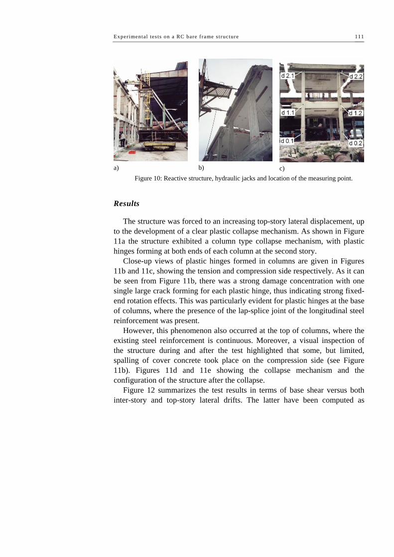
Experimental tes ts on a RC bare frame s tructure 111
a)
b)
c)
Figure 10: Reactive structure, hydraulic jacks and location of the measuring point.
Results
The structure was forced to an increasing top-story lateral displacement, up to the development of a clear plastic collapse mechanism. As shown in Figure 11a the structure exhibited a column type collapse mechanism, with plastic hinges forming at both ends of each column at the second story.
Close-up views of plastic hinges formed in columns are given in Figures 11b and 11c, showing the tension and compression side respectively. As it can be seen from Figure 11b, there was a strong damage concentration with one single large crack forming for each plastic hinge, thus indicating strong fixed-end rotation effects. This was particularly evident for plastic hinges at the base of columns, where the presence of the lap-splice joint of the longitudinal steel reinforcement was present.
However, this phenomenon also occurred at the top of columns, where the existing steel reinforcement is continuous. Moreover, a visual inspection of the structure during and after the test highlighted that some, but limited, spalling of cover concrete took place on the compression side (see Figure 11b). Figures 11d and 11e showing the collapse mechanism and the configuration of the structure after the collapse.
Figure 12 summarizes the test results in terms of base shear versus both inter-story and top-story lateral drifts. The latter have been computed as

Chapter IV
112
average values using displacements monitored at points d1.1, d1.2, d2.1 and d2.2 (see Figure 10c). Differences between measures taken at points d1.1 and d1.2, as well as those taken at points d2.1 and d2.2, revealed negligible, thus indicating practically no-torsion of floor-slabs at both stories. Moreover, displacements of both point d0.1 and d0.2 (see Figure 10c), which are not explicitly reported in a graph, were in the order of few millimetres at the peak load, thus indicating a negligible sliding of the foundation beams.
Then, Figure 12a shows the base shear vs. first-story displacement, the base shear vs. second-story displacement relationships. Figure 12b shows the base shear versus first-story drift, the base shear versus second-story drift and the base shear versus the top drift angle. Notwithstanding the fact that no plastic hinge could have been visually detected in the first story of the structure, it is apparent from the measured lateral drifts that some non-linear response occurred also there.
This is emphasized by the arrows drawn on the base shear vs. lateral drift graphs of Figure 12b. After the achievement of the peak load, the structure was completely unloaded and then reloaded in order to measure the residual structure strength. As shown in Figure 12b, this residual strength was measured to be about 53% of the peak value.
After the reloading the measures of lateral displacement are unsure and they are not reported.
b) d)
a) c) e)
Figure 11: Damage results of the first test.

Experimental tes ts on a RC bare frame s tructure 113
a)
b) Figure 12: Results of the pushover test.
Experimental results can be compared with a simply application of the
static theorem of plastic analysis considering the sequent collapse mechanism:

Chapter IV
114
Figure 13: Simplified collapse mechanism of the RC structure.
Imposing the equivalence of the virtual work performed by the external
force, considered unitary, and the virtual work performed by the internal force, it can be easily obtained the multiplier collapse factor of external force (see Figure 13). The columns plastic bending moment was considered constant and equal to the plastic moment of the column cross section when only the gravity loads acting:
kNhMMFh u
u 28.7480.2
0.268842 =×
=×
=⇒×××= αφφα (1)
In the expression the ultimate bending moment of the column cross-section
has been considered equal for all the collapsed sections and the effect of the different axial load was not considered.
It must be emphasized that the structure was loaded with only a top–story lateral force, with the first-story being not externally loaded. If the same structure would have been subjected to a lateral load pattern involving also a lateral force applied at the first story, the structure will have collapsed by the same type of collapse mechanism, but with plastic hinges forming in the first-story columns.
This can be easily predicted by simple limit-analysis calculations, taking into account the position of the resultant base shear. Besides, this predicted plastic collapse mechanism is also testified by another test, which was carried out on another structure of the ILVA-IDEM project (the fifth structure from the left in Figure 1b).

Experimental tes ts on a RC bare frame s tructure 115
4.4 REPAIRING AND UPGRADING OF THE TESTED STRUCTURE
Design of the seismic repairing/upgrading system
The main aim of the repairing/upgrading system design was to change the failure mode from a column type to a beam type collapse mechanism, forcing plastic hinges to form in the T-section floor-beams. Then, columns had to be reinforced in order to improve their bending strength. The FRP materials used for this rehabilitation were commercial products of MAC-Degussa. In particular, pre-formed high-strength carbon strips having nominal width and thickness of 50 mm and 1.4 mm, respectively, have been used (MAC-LM 5/1.4). Mechanical properties suggested by the producer have been adopted. In particular, the Young modulus of composites considered in the numerical analysis is 165 GPa. The MAC system makes uses of an epoxy paste, applied after an epoxy primer, as adhesive joint. The preliminary design has been based on the following simplified assumptions. The acting axial force has been assumed equal to that computed with reference to the original (non-repaired) structure. In fact, with the same gravity loads, the main design objective is to repair the structure, by giving it at least the same lateral load resistance exhibited in the original conditions. Concrete has been assumed non-confined, with the Young modulus and the compressive maximum stress equal to the average values coming from the laboratory tests on the sample specimens and with an ultimate strain equal to 0.004. The stress-block approximation was assumed, with a block area coefficient equal to 0.8. The contribution of existing steel rebars has been neglected, in such a way to assign the whole tension to the new FRP reinforcement. The contribution of C-FRP on the compression side has been also neglected. Using classical assumptions for the analysis of sections in bending, results summarized in Table III have been generated. In this Table, for a fixed ultimate concrete strain (εcu), the neutral axis position (xc), the required ultimate strain of fibres (εf) and the ratio (α) between ultimate moments of the fibre-reinforced and original section are given as a function of the FRP strip area (Af). As it can be expected, Table 5 indicates that increasing fibres area increases the bending
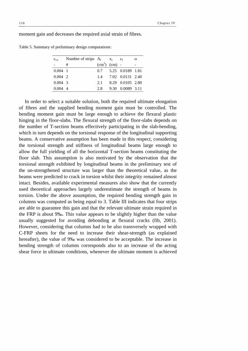
Chapter IV
116
moment gain and decreases the required axial strain of fibres.
Table 5. Summary of preliminary design computations:
εcu Number of strips Af xc εf α - # (cm2) (cm) - - 0.004 1 0.7 5.25 0.0189 1.810.004 2 1.4 7.02 0.0131 2.400.004 3 2.1 8.29 0.0105 2.800.004 4 2.8 9.30 0.0089 3.11
In order to select a suitable solution, both the required ultimate elongation
of fibres and the supplied bending moment gain must be controlled. The bending moment gain must be large enough to achieve the flexural plastic hinging in the floor-slabs. The flexural strength of the floor-slabs depends on the number of T-section beams effectively participating in the slab-bending, which in turn depends on the torsional response of the longitudinal supporting beams. A conservative assumption has been made in this respect, considering the torsional strength and stiffness of longitudinal beams large enough to allow the full yielding of all the horizontal T-section beams constituting the floor slab. This assumption is also motivated by the observation that the torsional strength exhibited by longitudinal beams in the preliminary test of the un-strengthened structure was larger than the theoretical value, as the beams were predicted to crack in torsion whilst their integrity remained almost intact. Besides, available experimental measures also show that the currently used theoretical approaches largely underestimate the strength of beams in torsion. Under the above assumption, the required bending strength gain in columns was computed as being equal to 3. Table III indicates that four strips are able to guarantee this gain and that the relevant ultimate strain required in the FRP is about 9‰. This value appears to be slightly higher than the value usually suggested for avoiding debonding at flexural cracks (fib, 2001). However, considering that columns had to be also transversely wrapped with C-FRP sheets for the need to increase their shear-strength (as explained hereafter), the value of 9‰ was considered to be acceptable. The increase in bending strength of columns corresponds also to an increase of the acting shear force in ultimate conditions, whenever the ultimate moment is achieved

Experimental tes ts on a RC bare frame s tructure 117
in columns. Then, to complete the preliminary design, shear strength of columns has been checked. Based on the original steel transverse reinforcement, the need to integrate shear strength has been estimated using available technical formulations (fib, 2001). Wet lay-up C-FRP sheets produced by MAC-Degussa were used for this purpose (product commercial name: MBrace FIBRE C1-30). One single ply of high-strength carbon fibres (Young modulus of 230 GPa, average tensile strength of 3000 MPa, equivalent thickness of dry material equal to 0.165 mm, nominal width of 300 mm) was computed to add enough shear strength. The overlapping joint was fixed equal to 100 mm as suggested by the Producer. Transverse FRP sheets also have one more important function: they reduce the local buckling free-length of longitudinal strips, which is essential in the seismic strengthening of columns where each strip is alternately subject to tension and compression. Finally, the transverse sheets do also give additional confinement to the concrete section. Figure 14 summarizes the repairing system design composed by C-FRP strips along the column axis and C-FRP sheets in the transverse direction. Strips have been interrupted at mid-height of columns. At the top-level ending of fibres, the composite strips have been adequately anchored by extending the column for 300 mm and applying a confining transverse sheet.
Figure 14: Output of the composite system design.

Chapter IV
118
Once the fibre reinforcement has been quantitatively chosen, a more detailed moment-curvature analysis of the transverse cross-section has been carried out, using a fibre discretisation of the cross-section (see Figure 15a).
For this purpose the finite element program OpenSEES (Mazzoni et al., 2005) has been adopted. In particular, the effect of confinement of both transverse composite sheets and existing steel stirrups has been taken into account. Namely, unconfined concrete has been modelled by the stress-strain relationship suggested by Popovics (1973), while the confinement effect has been considered using the Spoelstra & Monti suggestion (1999).
The modeling of confined and un-confined concrete has been done using the Concrete01 material. Numerical moment-curvature relationships are given in Figure 16a, and the axial force-bending moment interaction domain is reported in Figure 16b.
Contribution of longitudinal steel reinforcement was neglected. Stress-strain curve of longitudinal FRP strips has been modelled as a linear elastic material defining the Young modulus of composite materials, the ultimate strain capacity and neglecting the contribution in compression of the material by means of Elastic-No Tension material command.
In order to modelling the column cross section a zero-length section was used. For the numerical analyses the integrator displacement control, Newton algorithm and Static analysis type has been used.
a)
b)
Figure 15: Fiber discretisation of the columns cross section for moment-curvature analysis. Several moment-curvature analyses have been conducted in order to
evaluate the behaviour of column reinforced section. Analyses have been

Experimental tes ts on a RC bare frame s tructure 119
conducted for different axial load intensity. In particular the ratio between the applied axial load (N) and the ultimate strength of column in compression (Nu), varying in the range of 0.00 to 0.92 passing trough the sequent values: 0.15, 0.44, 0.58 and 0.80. As it can be easily noted the moment-curvature diagram is influenced by the N/Nu ratio as in term of strength, stiffness and ductility. The shape of the moment-curvature diagram varied from a linear aspect for N/Nu=0.00 to a considerable non-linear aspect for N/Nu=0.92. The major tensile strength can be attributing to the presence of FRP longitudinal strips. The second phase of this study was based on the definition of M-N interaction domain of cross-section of FRP reinforced columns. For the construction of M-N domain has been fixed the ultimate strain of concrete in compression as εcu=0.004 and the ultimate strain of longitudinal strips as εfu=0.008. For different values of axial load, the values of ultimate bending have been determined in order to define the different point constituting the limit surface of domain. From a direct comparison between the plastic domain of RC column cross-section and the plastic domain of FRP reinforced column cross-section is clearly visible the increase of strength capacity in the tensile side. Thus is justifiable if the contribute of FRP in tensile is considered. In the compression side, the gap existing between the two plastic surfaces is due to the neglecting of contributing in compression of steel rebars and the FRP longitudinal strips, hence the strength in compression was give by only the concrete.

Chapter IV
120
Figure 16: a) Moment-curvature relationships, b) axial force-bending moment interaction domain.
Concrete repairing and FRP strengthening
After the pushover test of the original structure was completed, columns were first re-placed in a sub-vertical position (see Figure 17a). Then, the fractured concrete was removed from plastic hinge zones, which were cleaned of debris and fine particles using water under pressure. Water had also the function of maintaining high humidity on the existing concrete surface, for a successful application of the reconstruction concrete. The latter was a premixed, bi-component, expansion contrasting, rehodynamic, resisting to aggressive environmental actions, concrete produced by MAC-Degussa (commercial name EMACO Formula B1). At the same time, vertical holes were prepared through the horizontal floor-slabs, near columns, in order to allow the subsequent application of continuous fibre strips (see Figure 17b). Finally, a premixed, bi-component, fibre-reinforced with stainless steel fibres, expansion contrasting, tixotropic mortar was manually applied for having a smooth surface, thus completing the first main stage of the repair process (the commercial name of the mortar used is EMACO Formula System S1, also produced by MAC-Degussa).
Column corners were rounded with a radius of curvature equal to 20 mm.

Experimental tes ts on a RC bare frame s tructure 121
After about five weeks from the concrete repair, the composite laminates were applied and the vertical holes previously made were filled with the EMACO Formula B1 special concrete (see Figure 19). After about another eight weeks, the specimen was tested.
Figure 17: Some pictures showing the damage state of columns after the pushover test and the re-centring operation, as well as the holes made in the slab for passing through with
reinforcing fibres.
a)
b)
c)
Figure 18: Composite materials used for the seismic upgrading: a) MAC LM5/1.4, b) MBrace FIBRE C1-30, c) MBT-MBrace Primer.
Bar buckling

Chapter IV
122
a)
b) c) d)
Figure 19: Application of FRP materials: a) primer; b) epoxy paste; c) C-FRP strips positioning; d) transverse C-FRP sheets applied.
4.5 THE STATIC CYCLIC TEST OF THE UPGRADED STRUCTURE
Loading and measuring devices
The second part of this experimental research was partially covered by a financial support. This allowed the design and construction of a new reacting frame, which is shown in Figure 20a. As it can be seen, a vertical steel beam was used for distributing the applied lateral force between the two stories of the structure to be tested. Applying the lateral force at two-thirds from the bottom support of this vertical beam, it would reproduce a lateral load pattern as close as possible to the inverted triangular distribution often assumed in theoretical pushover studies.
Figure 20b shows the diastimeter used for measuring the lateral displacements of the two stories of the structure, in a similar way as used for the first test on the initial un-strengthened structure. Figures 20c and 20d are a close-up view of the two hydraulic jacks used for applying the lateral force on the structure. Since these jacks are able to apply the load in one single direction, they were placed in juxtaposition in such a way to work in both two directions of loading and apply a cyclic lateral loading history.

Experimental tes ts on a RC bare frame s tructure 123
c)
a)
b) d) Figure 20: The FRP-reinforced structure ready for testing loading, measuring devices and
hydraulic jacks.
Results
The FRP-strengthened structure was subjected to a cyclic loading history, up until the displacement capacity of the load-actuators was completely exhausted. Figures 21 and 22 show the damage pattern evidenced during and at the end of the test.
The damage pattern (Figure 21) consists of flexural plastic hinges forming at the base of the first-story columns (Figures 21b and 21c) and in the T-section floor-beams at the first story slabs (Figures 21d and 21e). In particular, the bending contribution of the generic floor-beam depends on its location, because of the torsional flexibility of the longitudinal supporting beams. It must be noted that, in the structure under study, there are two portions of longitudinal beams having different end-restraints: the portion located in between two columns is torsional restrained at both ends, whilst the other parts are torsional restrained at only one end.
Experimental results show that the floor-beams supported by the free-ending portions of longitudinal beams are all contributing to the lateral strength of the structure by bending up to flexural plastic hinging at their ends. On the contrary, bending of the floor-beams supported by the portions of

Chapter IV
124
longitudinal beams that are torsional restrained at both ends is smaller as far as the T-section floor-beam is close to the mid-point of the longitudinal beam span. This is well evidenced by the residual cracking pattern, which was observed on the structure at the end of the test and is shown in Figures 21d and 21e. The concrete cracking extends for all the length of the longitudinal beams for the free-ending portions of them (Figure 21d), whilst it is confined to a small extent on the internal side where the longitudinal beams are torsional restrained at both two ends (Figure 21e). The latter portion of the slab, which was severely cracked by flexure, has been measured to be about 250÷300 mm, which is a value slightly larger than the thickness of the slabs.
As it can be observed, all plastic hinges exhibited one single large crack, indicating important bond-slip effects, what was well expected on the basis of the previous test.
Other types of damage are present on the structure. In particular: a) peeling-off of C-FRP strips at a wrong end detail execution; b) local buckling of longitudinal strips in the node zone (Figure 22).
Figure 23 shows the results of the test in quantitative terms. The base shear vs. top-story lateral displacement relationship is depicted in Figure 23a, while Figure 23b illustrates the base shear vs. first-story lateral displacement relationship.
Top-story and first-story drift angles are also reported, dividing lateral displacements by the top-story and first-story heights, i.e. by 6.60m and 3.30m, respectively. In Figure 23, measures taken at each of the reflecting prisms located on the structure are reported, namely: d1.1 and d1.2 for the first story; d2.1 and d2.2 for the second story (see Figure 20b).
For both two stories, the difference in the two measures taken is very small, being indistinguishable in the graphs and indicating negligible torsion of the slabs.
A rather stable inelastic response, up to the imposed maximum lateral displacements, can be observed.
Unfortunately the test had to be stopped before than the structure started to exhibit degradation, because the displacement capacity of the load actuator (±250 mm) was exhausted.

Experimental tes ts on a RC bare frame s tructure 125
b) d)
a) c) e)
Figure 21: Basic damage pattern of the FRP-strengthened structure.
Figure 22: Secondary damage pattern of the FRP-strengthened structure.

Chapter IV
126
a)
b) Figure 23: Results of the pushover test of the FRP-strengthened structure.
Original vs. upgraded structure response One of the main design objectives of the FRP-strengthening system was to
force plastic hinges forming in the horizontal slab beams rather than in the columns. The experimental results previously discussed demonstrate that this objective has been achieved.

Experimental tes ts on a RC bare frame s tructure 127
4.6 ORIGINAL VS UPGRADED STRUCTURE RESPONSE
Figure 24 illustrates the comparison between the monotonic pushover curve recorded for the original un-strengthened structure and the envelope curves of the cyclic test carried out on the FRP-strengthened structure. In Figure 24, both the envelopes of the positive and negative load-displacement relationships are reported. As discussed in the previous Sections, the static pushover test of the un-strengthened structure was obtained with the load applied only at the top story, whilst the cyclic static test of the FRP-strengthened structure was carried out applying forces both at the first and second story (according to an inverted triangular lateral load pattern). This could be thought to impair a direct comparison of the results in quantitative terms, as done in Figure 24. However, this direct comparison can be justified by the following considerations:
a) an inverted triangular lateral load pattern applied to the original un-strengthened structure would have produced a first-story sway collapse mechanism, which is deemed to be quite identical to the second-story mechanism exhibited during the test with the load applied only on the top;
b) the first and second story column sections, heights and reinforcement detailing are nominally identical;
c) as a consequence of points a) and b), the strength and lateral displacement capacity of the un-strengthened structure, in case of an inverted triangular lateral load pattern, are deemed to be not too much dissimilar from what recorded by applying the load only at the top story. A rather larger difference is deemed to exist in terms of initial stiffness.
As it can be seen in Figure 24, the strength of the FRP-rehabilitated structure is measured to be 86% larger than the initial value if the positive envelope is considered and 100% larger if the negative envelope curve is contemplated.
Analogously, the lateral top-displacement capacity is increased of about 100% of the initial value irrespective of the sign of the imposed displacement (strength degradation exhibited by the FRP-strengthened structure is considered negligible for both positive and negative loading direction up to a top-displacement of about 250 mm).

Chapter IV
128
0
20
40
60
80
100
120
140
160
0.00 0.05 0.10 0.15 0.20 0.25 0.30Top Displacement (m)
Bas
e Sh
ear (
kN)
FRP-Strengthened
Un-strengthened
NegativeEnvelope
Positive Envelope
Figure 24: Comparison of the initial vs. FRP-rehabilitated structure response.

Experimental tes ts on a masonry inf i l led RC structure 129
Chapter V Experimental tests on a masonry infilled RC structure
5.1 INTRODUCTION
The following experimentation has been made on a real reinforced concrete building. The building has been tested until collapse under lateral and horizontal load in its original configuration in order to take into account the presence of the stair, the partition walls and all the other constructive elements (internal walls, coverings, windows and door frames). The tested structure is located in the Bagnoli district of Naples, in the area of the previous steel mill named ILVA.
The building under study can be considered as representative of a large number of existing RC buildings in the South of Italy, built after WW2 during the 50s, 60s and 70s when Naples was considered a non seismic area. Figure 1a shows the building at the beginning of the investigation.
Results of an experimental/numerical investigation on the lateral-load response of a real RC structure seismically upgraded by means of carbon fiber materials (C-FRP) are presented and discussed. The structure under investigation was first tested in its original condition, under a cyclic loading test. A typical collapse mechanism of masonry infilled structures was evident by a formation of diagonal cracks into the partition walls..
After the first experimental test the structure was re-centred, repaired and
Chapter V
130
upgraded by means of C-FRP in the form of Near Mounted Surface Bars (NMS-B).
The reinforced structure has been tested under cyclic loading conditions showing the successful implementation of C-FRP, with an important improvement of lateral displacement capacity.
After the physical testing activity, a numerical study has been conducted, investigating the ability of current structural modeling options to correctly capture the observed lateral load response of both the original and FRP-strengthened structures. The model calibrating process considered the experimental evidence and the actual material properties. Good agreement between numerical and experimental results was achieved. Dynamic analysis of both the initial and the strengthened structure has been also carried out, highlighting the difference of both structures in terms of fundamental periods and vibration modes.
Description of the building
The geometrical survey and the constructional details in the original design drawings clearly show that the structure has been designed to resist vertical loads only. Following figures show two drawings representing essential characteristics of the RC frame structure at first and second floor. At first floor, all beams have rectangular 20cmx60cm cross–section except the transverse beam in X direction that is 25cmx60cm. At second floor, all beams are rectangular 15cmx60cm cross–section, except for the transverse beam in X direction which is 25cmx60cm. All columns have square 30cmx30cm cross–section, with twelve longitudinal ribbed bars (12 mm in diameter) as reinforcement uniformly distributed along the perimeter of the cross–section. The extrados floor heights, measured from foundations, are respectively 4.60 m at first floor and 8.95 m at second floor. Structural details are in accordance with the past italian non–seismic code. For example, transverse stirrups in beams and columns are discontinuous, largely spaced and not well bended inside the cross section. Also insufficient anchorage and incorrect overlaps of the longitudinal steel rebars can be observed, together with the absence of suitable confinement of joints, eccentricities in beam to column joints, scarce care of the resumptions of concrete casting of columns. The perimeter infill
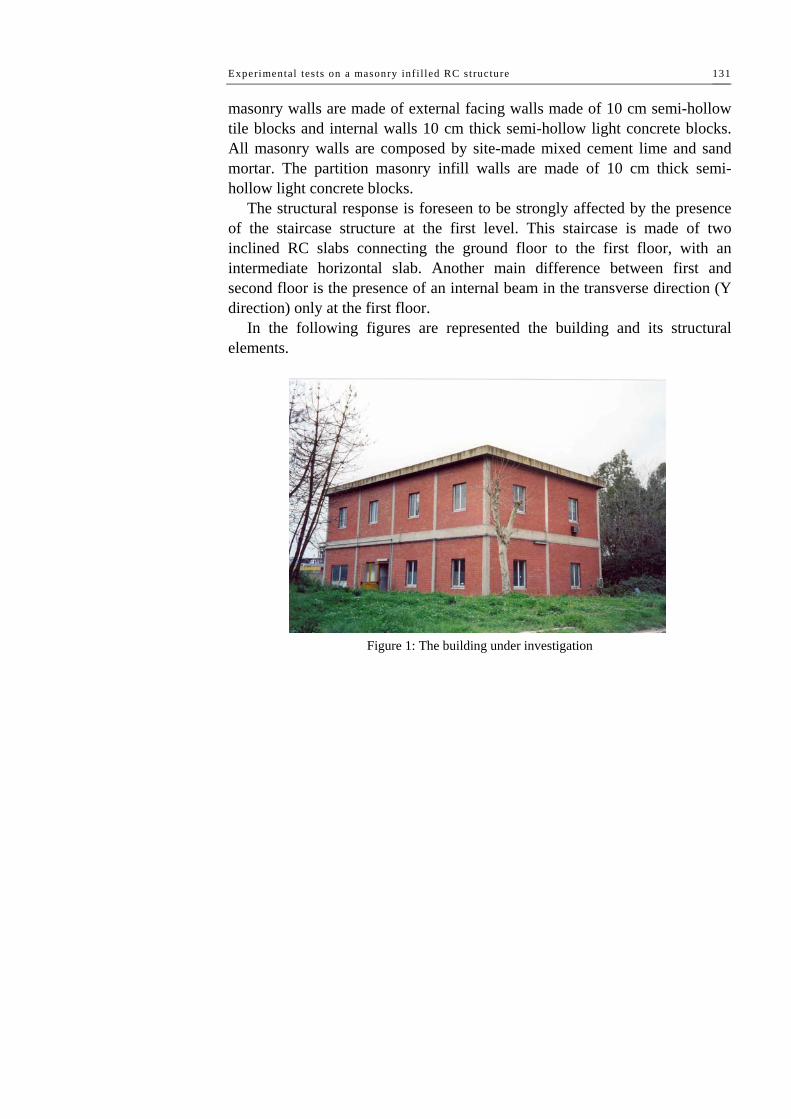
Experimental tes ts on a masonry inf i l led RC structure 131
masonry walls are made of external facing walls made of 10 cm semi-hollow tile blocks and internal walls 10 cm thick semi-hollow light concrete blocks. All masonry walls are composed by site-made mixed cement lime and sand mortar. The partition masonry infill walls are made of 10 cm thick semi-hollow light concrete blocks.
The structural response is foreseen to be strongly affected by the presence of the staircase structure at the first level. This staircase is made of two inclined RC slabs connecting the ground floor to the first floor, with an intermediate horizontal slab. Another main difference between first and second floor is the presence of an internal beam in the transverse direction (Y direction) only at the first floor.
In the following figures are represented the building and its structural elements.
Figure 1: The building under investigation

Chapter V
132
Figure 2: The building under investigation – first floor plan
Figure 3: The building under investigation - second floor plan

Experimental tes ts on a masonry inf i l led RC structure 133

Chapter V
134
Figure 4: Geometry and reinforcement of the existing structure.
5.2 THE PUSHOVER TEST OF THE ORIGINAL STRUCTURE
Loading and measuring devices
The building has been subjected to an horizontal charge which, simulating an action of seismic nature, has been applied to a part which represents the resultant of a distribution of triangular charge increasing to the top.
The only vertical loads have been only those produced by the building

Experimental tes ts on a masonry inf i l led RC structure 135
weight, including all the weights of elements of finishing (internal walls, inside and outside frames and some furnishings).
The lateral load has been applier by means of six hydraulic jacks each one having a maximum stroke of 60 cm and a higher flow rate equal o 496 kN in compression and 264 kN in tension (corresponding to a total force maximum of 2976 kN and 1584 kN respectively in push and in pull action).
They have been connected to a hydraulic pump by means of a circuit in order to guarantee always the same pressure in all the jacks. The jacks have been put at a height of 7,31 m and distant each other 3,64 m. The lateral load has been transferred to the two slabs of the building through a steel structure.
Figure 5: Reactive structure and hydraulic jacks.
Loading protocol and instruments
The loading protocol has foreseen three cycles of charge. In particular, the first cycle has been achieved first pushing the structure till the total force of +1872 kN, then inverting the loading direction till to reach the value of -1588 kN (maximum capability of the pulling jacks) at last the structure has been

Chapter V
136
unloaded. With the second cycle, like the first one, a maximum pushing force as
+2106 kN has been applied and a maximum pulling load as -1572 kN has been applied.
The third cycle, having the aim of bringing the structure at a very high level of damage, has foreseen the thrust of the building till the complete overcoming of the maximum carrying capability.
The total agent force, has been derived by the measure of the agent pressure, which has been monitored by a digital gauge with a precision of 1 bar.
The lateral displacementS of the building have been monitored by a Zeiss-Trimble S10 total station (Theodolite laser with a precision of 10 mm) by means of the application of reflecting targets. In particular, 8 important points have been monitored, 4 at first floor and 4 at second floor. The measures have been done at the end of each loading step.
In following figure the position of the measurement station and the reflecting targets are shown.
Figure 6: Position of station and reflecting targets.
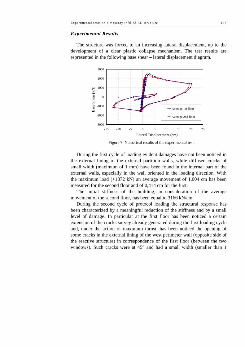
Experimental tes ts on a masonry inf i l led RC structure 137
Experimental Results
The structure was forced to an increasing lateral displacement, up to the development of a clear plastic collapse mechanism. The test results are represented in the following base shear – lateral displacement diagram.
-3000
-2000
-1000
0
1000
2000
3000
-15 -10 -5 0 5 10 15 20 25
Lateral Displacement (cm)
Bas
e Sh
ear (
kN)
Average 1st floor
Average 2nd floor
Figure 7: Numerical results of the experimental test.
During the first cycle of loading evident damages have not been noticed in
the external lining of the external partition walls, while diffused cracks of small width (maximum of 1 mm) have been found in the internal part of the external walls, especially in the wall oriented in the loading direction. With the maximum load (+1872 kN) an average movement of 1,004 cm has been measured for the second floor and of 0,414 cm for the first.
The initial stiffness of the building, in consideration of the average movement of the second floor, has been equal to 3166 kN/cm.
During the second cycle of protocol loading the structural response has been characterized by a meaningful reduction of the stiffness and by a small level of damage. In particular at the first floor has been noticed a certain extension of the cracks survey already generated during the first loading cycle and, under the action of maximum thrust, has been noticed the opening of some cracks in the external lining of the west perimeter wall (opposite side of the reactive structure) in correspondence of the first floor (between the two windows). Such cracks were at 45° and had a small width (smaller than 1

Chapter V
138
mm). The average movement of the second and the first floor in correspondence
of the maximum load (+2106 kN) have been respectively 1,318 and 0,779 cm, hile for the minimum applied load (-1572 kN) has been measured an average displacement of -0,717 cm at the second floor and -0,295 cm at the first floor. The initial stiffness has been 1161 kN/cm, equal to about 37% of the measured one at the beginning of the first cycle.
During the third cycle of loading protocol, the important phases of the behavior evolution identified by the points A, B, C, D, E and F, they can be identified in the following figure.
-3000
-2000
-1000
0
1000
2000
3000
-15 -10 -5 0 5 10 15 20 25
Lateral Displacement (cm)
Bas
e Sh
ear (
kN)
A B
C D E
F
Figure 8: Fundamental phases of structural behavior.
This phase of loading has been characterized by a further reduction of the
stiffness (924 kN/cm) equal to 29% of the measured one at the beginning of the second cycle by the achievement of the highest strength (2501 kN) and by the complete development of the collapse mechanism.
Later a short evaluation of the experimental results observed during the third cycle will be illustrated:
A) The structural response loses dramatically its linearity for a total load of 2350 kN. In correspondence of this point, on the first floor has been noticed the opening of the cracks directed to 45° in the external lining of the east perimeter wall (same side of the reactive structure) while the width of the cracks already noticed on the west side has increased during the second cycle

Experimental tes ts on a masonry inf i l led RC structure 139
of load. So we can say on these walls the collapse mechanism associated to the diagonal breaking for traction has been developing. The lateral displacement values were s1=1,249 cm and s2=2,106 cm.
Figure 9: Structural damage at the level A. B) The highest lateral carrying capacity has been of 2106 kN. It has been
drawn for an average displacement equal to s2=2,935 cm at the top floor and equal to s1=1,873 cm at the first floor. For this load value the damage was mainly in the building element of the first floor. For this level of deformation all the external walls of the first floor directed towards the load direction had clear crack patterns and there were detachments between the walls and the structure of reinforced concrete and they had cracks for local crushing.
On the west side, beside the increase of the width of cracks at 45° in the

Chapter V
140
wall panel between the two windows, in correspondence of the top right side of the next wall, the break for local crushing of the corners of the separation walls was early visible, due to the concentration of the horizontal forces transmitted by the reinforced concrete frame.
The damage of the separation walls in this place is accompanied by the evident crack of the head of the column which herald the cut break of such on element.
On the east side, in all the walls of the first order between the window and the column was evident the break at 45° due to the tension of diagonal tractions (collapse for diagonal break for traction). Moreover, on the east side, too, on the top left corner of the wall from the side of the reactive structure there is the local crushing of the separation walls. Inside the building, in the walls having a direction parallel to the thrust the width of the cracks had clearly increased.
The reached damage level is illustrated in the following figure.

Experimental tes ts on a masonry inf i l led RC structure 141
Figure 10: Structural damage on the west side at the level B.

Chapter V
142
Figure 10: Structural damage on the east side at the level B.
C) (F=2152 kN, s1=4,187 cm, s2=5,244 cm). The damage is mainly on the
first floor. In fact, the increase of lateral displacement id exclusively produced by the drift of the first floor while the inter-story drift of the second level suffered a light reduction.
D) The external damages of the building are shown for the west and the
east side in the figures n° 13 and 14. In particular, in the wall elements where the collapse mechanism was present for diagonal cracking, the cracks at 45° previously originated become wider and, in some cases, other cracks opened beside the previously existing cracks.
In the west wall interested till now in the collapse for local crushing of the corner there has been observed a crack at 45°. This phenomenon testified how the progressive damage of such element makes the collapse mechanism evolve into a mechanism for diagonal break. Moreover, at such level of deformations, it has been observed the complete development of the collapse for cut at the head of the external column on the west façade. In the west wall interested in a mixed mechanism local crushing-diagonal cracks, it was evident the collapse for the cut of the head of the column in correspondence of the corner.

Experimental tes ts on a masonry inf i l led RC structure 143
Figure 11: Structural damage on the west side at the level C.
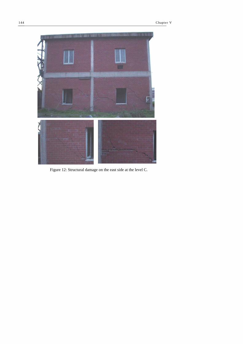
Chapter V
144
Figure 12: Structural damage on the east side at the level C.

Experimental tes ts on a masonry inf i l led RC structure 145
Figure 13: Structural damage on the west side at the level D.

Chapter V
146
Figure 14: Structural damage on the east side at the level D.
E) At the highest level of reached deformation the displacement of the first
floor and the second floor were respectively equal to s1 = 19,359 cm and s2 = 20,261cm. Such displacements had a value f the external force equal to 1425 kN. In this phase the floor mechanism on the first order was completely developed and the damage level was very relevant, both for the east and west sides.
In fact it was clearly visible the opening of the stirrups and the complete expulsion of the cover concrete on the top of external column for about 50 cm. On the external walls of the west side, in this phase, the collapse of part of the external lining above the central window has taken place.
F) The state of the building at the un-load of the structure is illustrated in
the following figures for external buildings element. The permanent deformations are significant and localized at the first order, as confirmed by the entity of the displacement and of the residual displacement.
Examining these figures we can notice the damage level and its localization on the first floor. In particular, beside the damages previously shown the unload phase has produced new partial collapses, especially in the internal lining of the internal of the internal partition walls.

Experimental tes ts on a masonry inf i l led RC structure 147
The permanent deformations in the structure have produced serious damages not only in the wall elements, but also in the reinforced concrete elements as the columns and the stairs structures.
Figure 15: Structural damage on the west side at the level F.

Chapter V
148
Figure 17: Structural damage on the east side at the level F.
Following figures shown the damage on the structure at the end of the test.
In particular we can observe the full collapse of external walls, the damage of the staircase and the plastic hinges developed at the ends of the columns.

Experimental tes ts on a masonry inf i l led RC structure 149
Figure 18: Structural damage at the end of the test.

Chapter V
150
5.3 REPAIRING AND UPGRADING OF THE TESTED STRUCTURE
Design of the seismic repairing/upgrading system
The main aim of the repairing/upgrading system design was to simulate a seismic upgrading of an existing building made up before of the emanation of the seismic code provisions. Several typologies of strengthening have been evaluated, but all based on the use of composite materials. In the following Figure are represented the different types of the studied seismic upgrading techniques.
In particular, the first, consist in to place in the mortar joints some horizontal FRP-rods, the second one, consist in to place the FRP reinforcement on the masonry walls as an X brace and, the last one, consist in to put on the perimeter masonry walls the FRP in form of fabric.
The selected solution is the first because it is not invasive, do not change the aesthetic appearance and by this solution is possible to reach some important improvement in ductility as confirmed by recent experimental tests conducted by Nanni et al (2004).

Experimental tes ts on a masonry inf i l led RC structure 151
Figure 19: Structural upgrading techniques.
Concrete repairing and FRP strengthening
After the first test, the building was partially repaired. In particular, only the perimeter damaged columns and the external masonry infills was rebuilt and strengthened by mans of FRP according to the Near Mounted Surface Bars techniques. The other elements, as internal columns, internal partition walls and staircase structure, were not repaired and those contributes in the structural response can be neglected.
The masonry panels were rebuilt using materials having geometrical and mechanical properties as close as possible to those of the original elements. After the erection of the external masonry infill panels, the facing walls were strengthened by means of the fiber reinforced polymers (FRP) structural repointing technique. This technique consists in placing composite FRP bars in the masonry bed joints, using a common mortar for bonding. Materials used for the repointing were:

Chapter V
152
- Sand-blasted carbon fiber rods (“MBarTM Joint” by Degussa Construction Chemical) having the following main geometrical and mechanical nominal properties:
- 1.5 mm tick and 5 mm wide rectangular cross-section; - Characteristic tensile strength (ACI 440.1R-01 2002): 1300 MPa; - Average tensile modulus (ACI 440.1R-01 2002): 70000 MPa; - Average ultimate deformation (ACI 440.1R-01 2002): 1.8%. - Pre-mixed, thixotropic, fiber reinforced, shrinkage compensated cement
mortar (“Emaco® Formula Tixo” by Degussa Construction Chemical) having the following main nominal
properties: - Compressive strength (28 days) (EN 12190 2000): > 60 MPa; - Adhesive strength (EN 12615 2001): > 6 MPa; - Modulus of elasticity (EN 13412 2003): > 28000 (± 2000) MPa. The installation procedure consisted in the following phases (Fig. 14): - (a) Grinding of joints: this phase consists of the cutting out part of the
mortar using a grinder; - (b) Installation of carbon fiber rods in the bed-joints previously raked out; - (c) Bonding of carbon fiber rods with the pre-mixed cement mortar. The repairing and strengthening of the damaged end portions of the
external columns was carried out by removing degraded concrete and reconstructing concrete covering with the “Emaco® Formula Tixo” pre-mixed cement mortar. Following figures show the used materials and some phases of the structural upgrading.
Figure 20: The brick elements used for the repairing.

Experimental tes ts on a masonry inf i l led RC structure 153
Figure 21: Some phases of the upgrading.
Loading protocol and instruments
The loading protocol has foreseen two cyclic loading. In particular, the first cycle has been achieved first pushing the structure till the total force of +510

Chapter V
154
kN, then inverting the loading direction till to reach the value of -633 kN at last the structure has been unloaded.
The second cycle, having the aim of bringing the structure at a very high level of damage, has foreseen the thrust of the building till the complete overcoming of the maximum carrying capability.
As for the first test, the lateral displacement of the building have been monitored by a Zeiss-Trimble S10 total station.
Figure 22: Position of station and reflecting targets.
Experimental Results
The response of the tested reinforced structure is showed, in the next Figure, in terms of base shear vs. average first- and second- story lateral displacements.
The prevalent failure modes were: sliding in the infills; masonry toe crushing and sliding in the infill; sliding and diagonal tension cracking. The damage of perimeter masonry walls at the point of maximum lateral displacement (+29 cm). At this lateral displacement, the damage at the first story was strongly increased and the out-of-plane collapse of the masonry portion between the two windows.
After reaching the value of the maximum lateral displacement (29 cm), the
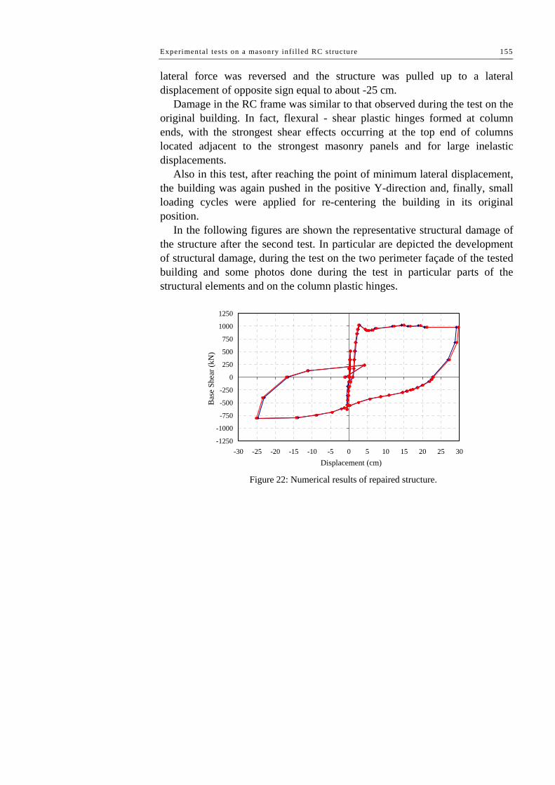
Experimental tes ts on a masonry inf i l led RC structure 155
lateral force was reversed and the structure was pulled up to a lateral displacement of opposite sign equal to about -25 cm.
Damage in the RC frame was similar to that observed during the test on the original building. In fact, flexural - shear plastic hinges formed at column ends, with the strongest shear effects occurring at the top end of columns located adjacent to the strongest masonry panels and for large inelastic displacements.
Also in this test, after reaching the point of minimum lateral displacement, the building was again pushed in the positive Y-direction and, finally, small loading cycles were applied for re-centering the building in its original position.
In the following figures are shown the representative structural damage of the structure after the second test. In particular are depicted the development of structural damage, during the test on the two perimeter façade of the tested building and some photos done during the test in particular parts of the structural elements and on the column plastic hinges.
-1250
-1000
-750
-500
-250
0
250
500
750
1000
1250
-30 -25 -20 -15 -10 -5 0 5 10 15 20 25 30Displacement (cm)
Bas
e Sh
ear (
kN)
Figure 22: Numerical results of repaired structure.

Chapter V
156
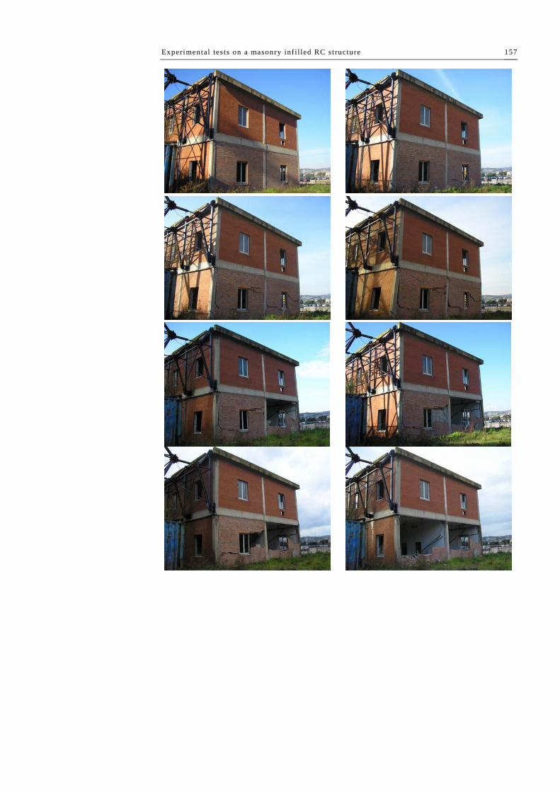
Experimental tes ts on a masonry inf i l led RC structure 157
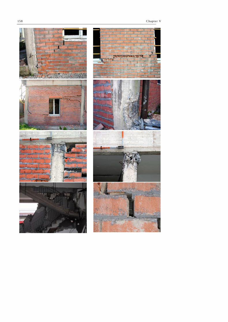
Chapter V
158

Experimental tes ts on a masonry inf i l led RC structure 159
5.4 ORIGINAL VS UPGRADED STRUCTURE RESPONSE
Comparing maximum lateral strengths obtained in the second and first test, a reduction of about 60%. This result can be attributed to the limited repairing carried out after the first test, which did not involve the staircase structure, the internal column and the internal partition walls.
A difference, in terms of maximum lateral displacement, can be noted by a comparison of structural response of the existing and of the repaired structure. In particular on the repaired structure it is possible to see a ductile behavior without any loss of strength, and for a similar lateral top displacement the damage on the repaired structure is smaller than the damage on the existing structure.
It may be noted that repaired infill walls exhibited different failure modes, characterized by a reduced influence of diagonal tension cracking. In addition it may be noted that the damage level in the repaired structure was smaller than that exhibited by the original building at the same level of lateral displacement.
-2000
-1500
-1000
-500
0
500
1000
1500
2000
2500
-30 -25 -20 -15 -10 -5 0 5 10 15 20 25 30
Lateral Displacement (cm)
Bas
e Sh
ear (
kN)
First Test
Second Test
Figure 22: Comparison of structural response in terms of base shear – lateral displacement.

Chapter V
160
-2000
-1500
-1000
-500
0
500
1000
1500
2000
2500
-0,08 -0,06 -0,04 -0,02 0 0,02 0,04 0,06 0,08
Drift angle (rad)
Bas
e Sh
ear (
kN)
First Test
Second Test
Figure 22: Comparison of structural response in terms of base shear – inter-story drift.
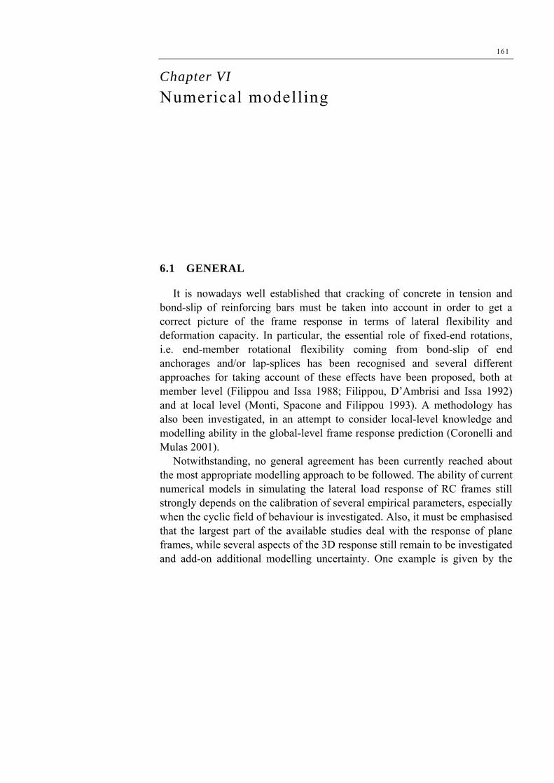
161
Chapter VI Numerical modelling
6.1 GENERAL
It is nowadays well established that cracking of concrete in tension and bond-slip of reinforcing bars must be taken into account in order to get a correct picture of the frame response in terms of lateral flexibility and deformation capacity. In particular, the essential role of fixed-end rotations, i.e. end-member rotational flexibility coming from bond-slip of end anchorages and/or lap-splices has been recognised and several different approaches for taking account of these effects have been proposed, both at member level (Filippou and Issa 1988; Filippou, D’Ambrisi and Issa 1992) and at local level (Monti, Spacone and Filippou 1993). A methodology has also been investigated, in an attempt to consider local-level knowledge and modelling ability in the global-level frame response prediction (Coronelli and Mulas 2001).
Notwithstanding, no general agreement has been currently reached about the most appropriate modelling approach to be followed. The ability of current numerical models in simulating the lateral load response of RC frames still strongly depends on the calibration of several empirical parameters, especially when the cyclic field of behaviour is investigated. Also, it must be emphasised that the largest part of the available studies deal with the response of plane frames, while several aspects of the 3D response still remain to be investigated and add-on additional modelling uncertainty. One example is given by the

Chapter VI
162
torsion-response modelling of beams, which are also subjected to flexure and shear. One more important example is given by the bi-axial flexural response of columns and their damage evaluation when bidirectional earthquake effects are taken into consideration (Faella, Kilar and Magliulo 2001).
Several additional and relatively novel difficulties must be faced when the seismic response of FRP-reinforced structures is being predicted. Stress-strain cyclic response of FRP-confined concrete and delamination of flexural FRP reinforcement are main examples of required knowledge for a correct analysis. The first explicitly needs for predicting the lateral deformation capacity, whilst the delamination problem mainly affects strength predictions.
Within the member-level FE modelling approach, cracking of concrete and bond-slip of steel rebars along the element length is often taken into account through the use of semi-empirical coefficients reducing the moment of inertia of the gross cross section. Also the shear area and the axial area can be reduced with analogous coefficients.
Within the lumped-plasticity modelling approach, bond-slip of end anchorages and/or lap-splices in critical regions of the member can be taken into account by adding some flexibility to the plastic hinge, thus simulating the well-known fixed-end rotation (FER) associated to large crack opening of the critical section.
In the following Sections, numerical models are presented, trying to reproduce, as close as possible, the experimental results previously discussed. The main objective was to verify the ability of relatively simple numerical models in capturing the measured physical response. Both the response of the original and FRP-strengthened structure are simulated, trying to keep coherence between models, meaning that common features of the two structures are simulated in the same manner.
In all numerical simulations, average values of main mechanical properties of materials are assumed. Thus, the cylindrical strength of concrete is fixed at 200 MPa, the Young modulus of concrete is taken as 16800 MPa, the yield strength of steel is assumed as equal to 440 MPa and 500 MPa for bar diameters of 12 mm and 10 mm, respectively.

Numerical modelling 163
6.2 MODELLING OF THE RC BARE FRAME STRUCTURE
Numerical model of RC structure
The second part of present activity consists in the numerical modeling of the original structure and FRP-reinforced structure. Numerical modeling has been made by means of the finite element program SAP 2000 NL (ver. 7.12).
Materials properties have been defined assigning values carried out by the materials test characterization. In particular: the elastic modulus of concrete, the Poisson coefficient and yielding stress of steel has been assigned.
After the materials definition it has been done the definition of elements, modeled as frame elements
The hypothesis of rigid floor slabs has done by means of diaphragm command. Each floor is characterized by three dynamics degree of freedom. Elements masses properties have been consented in master-nodes give by the mass center of each floor. For the evaluation of the mass a range criteria has been adopted. In the defined master-nodes. In following figures are represented the fundamental cross-section of the elements and the numerical model of the structure.
A good prediction of the experimental response by means of the FE analysis requires an accurate evaluation of the acting gravity loads.
Figure 1. Numerical model of RC structure.

Chapter VI
164
30,00
30,0
0
4 φ 12
50,00
10,00
2 φ 12
1 φ 8
Variable
50,0
0
4 φ 8
1 φ 12 Figure 2. Structural lements cross sections.
Numerical models results
As discussed in previous Sections, the original structure exhibited strong cracking and fixed-end rotations at column ends, where plastic hinges can be located.
As a first step, cracking of concrete along the member length has been simulated by reducing the gross moment of inertia of columns with a factor equal to 0.5. Inertia of floor-beams has not been reduced because negligible cracking was observed during the test. Fixed-end rotations were neglected at this stage, and infinite ductility was assumed for plastic hinges.
Numerical simulation results are summarized in Figure 31 (model O1), where comparison with experimental results is also illustrated. A quite good agreement is reached in terms of collapse mechanism and maximum strength, if P-Δ effects are taken into account. However, the stiffness prediction is poor, with the numerical model largely overestimating (elastic) stiffness. The reason for the latter discrepancy between the numerical model and the measured response is easily attributed to FER effects.
It could be foreseen that an improvement of the predicted response is obtained further reducing moments of inertia of columns, in order to capture the additional flexibility coming from bond-slip in bar anchorages and lap-splices at column ends. Figure 15 illustrates prediction of a numerical model characterized by this larger stiffness reduction in columns (model O2).
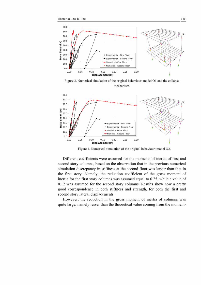
Numerical modelling 165
0.0
10.0
20.0
30.0
40.0
50.0
60.0
70.0
80.0
90.0
0.00 0.05 0.10 0.15 0.20 0.25 0.30Displacement (m)
Bas
e Sh
ear (
kN)
Experimental - First Floor
Experimental - Second Floor
Numerical - First Floor
Numerical - Second Floor
Figure 3. Numerical simulation of the original behaviour: model O1 and the collapse mechanism.
0.0
10.0
20.0
30.0
40.0
50.0
60.0
70.0
80.0
90.0
0.00 0.05 0.10 0.15 0.20 0.25 0.30Displacement (m)
Bas
e Sh
ear (
kN)
Experimental - First FloorExperimental - Second FloorNumerical - First FloorNumerial - Second Floor
Figure 4. Numerical simulation of the original behaviour: model O2. Different coefficients were assumed for the moments of inertia of first and
second story columns, based on the observation that in the previous numerical simulation discrepancy in stiffness at the second floor was larger than that in the first story. Namely, the reduction coefficient of the gross moment of inertia for the first story columns was assumed equal to 0.25, while a value of 0.12 was assumed for the second story columns. Results show now a pretty good correspondence in both stiffness and strength, for both the first and second story lateral displacements.
However, the reduction in the gross moment of inertia of columns was quite large, namely lesser than the theoretical value coming from the moment-

Chapter VI
166
curvature relationship in the cracked stage of the section (i.e. lesser than My/χy = 0.28, My and χy being the bending moment and curvature at yielding of the steel rebars). Besides, a residual discrepancy still persists, what can be again attributed to FERs and/or additional flexibilities like shear sliding in critical sections.
In order to make difference between different sources of lateral flexibility, a third modeling approach (model O3) has been pursued, introducing some flexibility in the plastic hinge for considering explicitly fixed-end rotations.
The moment vs. fixed-end rotation relationship is assumed to start rigid, with a zero rotation up to a bending moment equal to 0.1 the yielding moment. A 10% kinematics hardening has been assumed up to an ultimate value of the plastic hinge rotation (ϑu), where the bending moment resistance drops down to 0.3 of the yielding value. The fixed end rotation at yielding (ϑy) of the longitudinal steel rebars in columns has been computed starting from a simple modelling scheme, which assumes uniform bond stresses along the bar anchorages. A value of 0.004 rad resulted from this computation. However, a larger value of 0.005 rad was required to be adopted for second-story plastic hinges in order to get good matching of experimental results.
The ultimate value of the plastic hinge rotation has been instead computed using an empirical formulation coming from a regression analysis carried out by Panagiotakos and Fardis (2001), thus obtaining a value of 0.022 rad. Numerical values are in good agreement with those suggested by FEMA 356 (2000).
Numerical results are shown in Figure 34, where the best agreement obtained between the numerical model and the experimental results is shown. The numerical model is now able also to simulate the loss of strength measured for a top lateral displacement of about 12 cm.
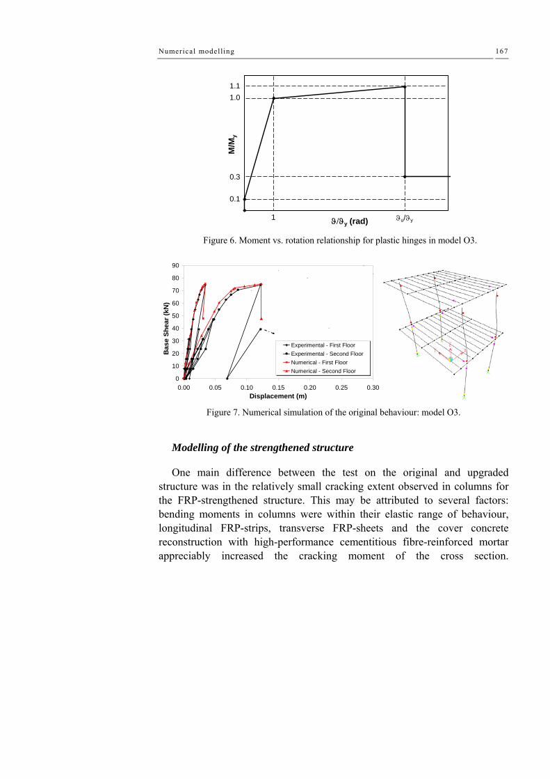
Numerical modelling 167
ϑ/ϑy (rad)M
/My
1
0.11
1.1
0.3
1.0
ϑu/ϑy
Figure 6. Moment vs. rotation relationship for plastic hinges in model O3.
0
10
20
30
40
50
60
70
80
90
0.00 0.05 0.10 0.15 0.20 0.25 0.30Displacement (m)
Bas
e Sh
ear (
kN)
Experimental - First FloorExperimental - Second FloorNumerical - First FloorNumerical - Second Floor
Figure 7. Numerical simulation of the original behaviour: model O3.
Modelling of the strengthened structure
One main difference between the test on the original and upgraded structure was in the relatively small cracking extent observed in columns for the FRP-strengthened structure. This may be attributed to several factors: bending moments in columns were within their elastic range of behaviour, longitudinal FRP-strips, transverse FRP-sheets and the cover concrete reconstruction with high-performance cementitious fibre-reinforced mortar appreciably increased the cracking moment of the cross section.

Chapter VI
168
Consequently, no reduction was applied in columns gross moment of inertia. At a first stage, fixed end-rotations have been neglected and no limit has
been placed on the inelastic hinge rotation capacity, thus following the same approach used for simulating the response of the original structure.
Plastic strength of beams in torsion was computed according to standard models (Eurocode 2, 2004). Using also available technical literature (Park and Paulay, 1975), the practical coincidence of cracking and ultimate moments of beams in torsion was ascertained, thus allowing the adoption of an elastic-perfectly plastic torque moment vs. rotation relationship. It is worth noting that this modelling of beams in torsion was also adopted in the simulation of the original structure behaviour, but no mention was made previously of this aspect because beams in the original structure were predicted to maintain their integrity in torsion (in agreement with experimental results).
Numerical results are shown in Figure 35 (model S1). A good correspondence with experimental results has been achieved, with the stiffness and strength of the real structure slightly larger than predicted. This result clearly suggests that fixed-end rotations and limited inelastic rotation in plastic hinges had no significant effect on the global response. This is also testified in Figure 37, where the numerical simulation (S2) takes now account of both effects. A relatively small difference between model S1 and S2 can be observed. The stiffness of model S2 is not too much smaller than the stiffness of model S1, and the ultimate hinge rotation is attained for a top lateral displacement larger than the maximum reached during the test. The latter observation holds true even if the hinge rotation capacity is set equal to the value correspondent to the original conditions, i.e. neglecting benefits coming from C-FRP confinement.
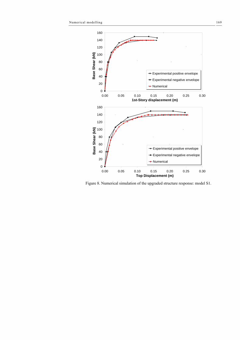
Numerical modelling 169
0
20
40
60
80
100
120
140
160
0.00 0.05 0.10 0.15 0.20 0.25 0.301st-Story displacement (m)
Bas
e Sh
ear (
kN)
Experimental positive envelope
Experimental negative envelope
Numerical
0
20
40
60
80
100
120
140
160
0.00 0.05 0.10 0.15 0.20 0.25 0.30Top Displacement (m)
Bas
e Sh
ear (
kN)
Experimental positive envelope
Experimental negative envelope
Numerical
Figure 8. Numerical simulation of the upgraded structure response: model S1.
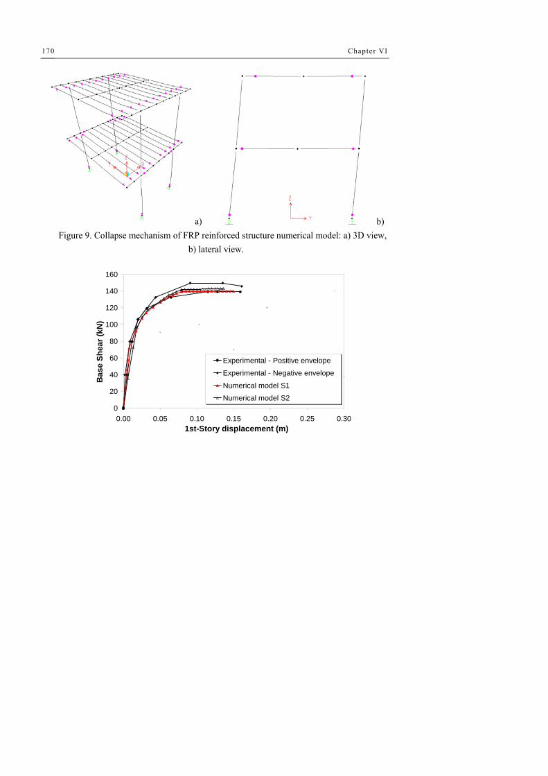
Chapter VI
170
a) b) Figure 9. Collapse mechanism of FRP reinforced structure numerical model: a) 3D view,
b) lateral view.
0
20
40
60
80
100
120
140
160
0.00 0.05 0.10 0.15 0.20 0.25 0.301st-Story displacement (m)
Bas
e Sh
ear (
kN)
Experimental - Positive envelope
Experimental - Negative envelope
Numerical model S1
Numerical model S2

Numerical modelling 171
0
20
40
60
80
100
120
140
160
0.00 0.05 0.10 0.15 0.20 0.25 0.30Top Displacement (m)
Bas
e Sh
ear (
kN)
Experimental - Positive envelope
Experimental - Negative envelope
Numerical model S1Numerical model S2
Figure 10. Numerical simulation of the upgraded structure response: model S2.
6.3 DYNAMIC IDENTIFICATION RC BARE FRAME STRUCTURE
Dynamics properties of the original structure, in terms of periods and mode of vibrations are deducted by means of SAP 2000 program using the built numerical model. A calculation of masses has been give by the knowledge of structural elements geometry and their weight
First, it was determined the position of the centre of mass of each floor. The determination of the center of mass consent the correct evaluation of polar inertia moment considering the contribution of each one structural element afferent to the generic floor.
The calculated values of seismic masses and rotational masses have been assigned at the defined master nodes. The following table shows the period of vibration, the frequency and the participations factor of each mode.
From presented figure and table it can be easily derived some information about the dynamics behavior of analyzed structure. The fundamental period of vibration is equal to 0.66 sec. For a RC structure, constituted by only two floors the typical fundamental periods about 0.20 sec. In this case, the period has a high value because the considered mass don not contain the accidental load and the structure is devoid of partition walls, floor and other finishing elements. No interference is evident through the successive mode. The figure

Chapter VI
172
showing the trend of participants masses denote the regular behavior of the structure, or rather, the first and the second modal shape are translational type whit the first mode interesting the direction characterized by a minor stiffness, and the third modal shape is purely torsional.
A comparison between experimental results and numerical results has been done in terms of dynamics frequencies. The experimental result was compared with numerical results carried out by the built numerical model. Hence, considering the reduction factors defined in the precedent section the scatter between numerical and experimental values of frequencies is about 2% for the first mode with a maximum of 11% for the sixth modal frequencies having a participations factor of 1%.
The same approach has been done for the C-FRP reinforced structure in which has not been considered the reduction factors. In this case, unitary coefficient has been adopted for all the structural elements. Following figure shown the difference between both the experimental and numerical results in the original structure and the difference for the upgraded structure.
0.00
0.20
0.40
0.60
0.80
1.00
1.0 2.0 3.0 4.0 5.0 6.0Number of mode
Mas
s ra
tio
Ux Uy Rz
Figure 11. Frequencies of vibration: comparison between numerical and experimental results.

Numerical modelling 173
Modes Period Frequency Eigenvalue # sec cyc/sec rad2/sec2 1 0.66 1.51 90.19 2 0.56 1.77 124.09 3 0.45 2.19 190.32 4 0.21 4.69 868.63 5 0.20 4.86 935.0 6 0.16 6.04 1440.2
Table I. Modal periods and frequencies.
0.00
1.00
2.00
3.00
4.00
5.00
6.00
7.00
8.00
9.00
1.0 2.0 3.0 4.0 5.0 6.0Number of modal period
Freq
uenc
es (H
z)
Experimental resultsUnitary coefficientsReduced coefficients
Figure 12. Frequencies of vibration: comparison between numerical and experimental
results.
first mode second mode third mode

Chapter VI
174
fourth mode fifth mode sixth mode
Figure 13. The six modes of vibration of the original structure.
first mode second mode third mode
fourth mode fifth mode sixth mode
Figure 14. The six modes of vibration of the reinforced structure.

Numerical modelling 175
6.4 DYNAMIC IDENTIFICATION OF THE MASONRY INFILL RC STRUCTURE
Preliminary model
In order to plan the experimental dynamic tests, a preliminary numerical model of the structure (as shown in Figure 3) has been developed by using the well-known commercial software SAP2000 (version 8.2.3).Through this study, an initial assessment of the natural frequencies of the system and the relevant vibration modes have been obtained. In such a way, it was possible to subsequently fix a suitable range of sampling frequencies of signals, as well as to establish an optimal position of the measuring points.
Inertia has been lumped in the centroid of masses at each floor, where the presence of the rigid diaphragm has been simulated allowing to have only three dynamic degrees of freedom at each floor, i.e. two translations and one torsional rotation. Moreover, the presence of perimetric and partition walls has not been purposely taken into account in this model, in order to understand how these elements, usually considered as non-structural, can influence the global response.
The results of this numerical analysis are presented in Table 3.1 and Table 3.2 in terms of masses, periods and modal participating masses. The modes of vibration are shown in Fig.4.
Figure 15. Numerical model of existing structure.

Chapter VI
176
Translational mass Rotational mass
kNs2/m kNm2 1°floor 196.864 10763.548 2°floor 146.894 7182.155
Table II. Dynamic masses lumped at centroid of floors
Period Sec
Frequency Hz
Mx %
My %
SumMx %
SumMy %
Mode 1 0.814 1.23 42.4 27.1 42.4 27.1 Mode 2 0.783 1.28 28. 57.4 70.5 84.5 Mode 3 0.652 1.53 21.4 1.8 91.9 86.3
Table III. Dynamic properties of the model: periods, frequencies and modal participating masses
From the data reported in Table 3, it is evident that there is an important
coupling between torsional and translational vibration modes. Consequently, the participating mass associated to the first vibration mode is only 42.4%. In order to highlight this aspect, the orthonormalized modal shapes are plotted in Figure 4.
1 modal shape
0
1
2
-0.08 -0.06 -0.04 -0.02 0 0.02 0.04 0.06 0.08
floor
Ux 1 mode Uy 1 mode Rz*r 1 mode
3 modal shape
0
1
2
-0.08 -0.06 -0.04 -0.02 0 0.02 0.04 0.06 0.08
floor
Ux 3 mode Uy 3 mode Rz*r 3 mode
2 modal shape
0
1
2
-0.08 -0.06 -0.04 -0.02 0 0.02 0.04 0.06 0.08
floor
Ux 2 mode Uy 2 mode Rz*r 2 mode
Figure 16. The first three modal shapes

Numerical modelling 177
As far as the first mode is concerned, referring to relative floor rotation, the
torsional effects at the first story are stronger than those at the second story, because of the presence of the staircase structure and one stiff beam only at the first floor, as previously mentioned. For the second mode, the torsional-translational coupling is less important even if it is not possible to identify the direction of translation. The third mode shows that the torsional component is prevailing.
Description of test setup
Tests have been carried out in cooperation with "STRAGO s.r.l." which furnished acceleration transducers, the acquisition system, the vibrodyne and the software for data processing.
Acceleration transducers
The structural response has been measured using 16 accelerometers
(Figure. 17), having the following technical characteristics: - Type of accelerometer: Force balance - Bandwidth: DC – 200 Hz - Full scale range: ± 1g - Sensitivity: 10V/g - Linearity: < 1000μg/g - Hysteresis: <0.1% of full scale - Cross-axis sensitivity:<1% (including misalignment)
Figure 17. The adopted accelerometer.

Chapter VI
178
Transducers have been fixed to the roof structure by means of an aluminum
base and fastening screws. The position of the accelerometers has been chosen in such a way to correctly record the foreseen modes of vibration of the structure (Ren et al.,2004). Six accelerometers were fixed on the first floor, while the remaining were placed on the second floor, where the vibrodyne was also positioned (see figure 6).
In order to have a good sample of the acceleration signals induced by the sinusoidal force of the vibrodyne and also to control the measures taken at other data acquisition channels, two "reference" sensors (number 14 and 15 in Figure 6) were placed near the vibrodyne.
The plan disposition of accelerometers on the two floors is shown in Figure
6, along with the position and orientation of the vibrodyne. Arrows define the positive direction of each measure.
1
3
05
4
6
YP5 P4 P3 P2 P1
P11 P10 P7P8P9 P6
P12P13P14P15P16P17

Numerical modelling 179
15
14
1213
11
29
7
810
P17 P16 P15 P14 P13 P12
P11P10 P9 P8 P7 P6
P1P2P3P4P5X
Y
Vibrodyne3
2.530°
Figure 18. The position of vibrodine.
Acquisition system
The analogical signals were acquired by a digital recorder (National
Instruments, model PXI-1042) with two cards of acquisition (NI 4472) having 8 architecture parallel channels with the precision of 24 bit and frequency of sampling equal to 102.4Ksamples/sec.The whole process of acquisition is driven by a software written in the programming language Labview 7.0. This software allows the acquisition of all signals and the real time visualization of the accelerograms and the Fourier Spectra to be carried out.
Figure 19. The acquisition system PXI–1042.
2nd card with 8 channels
1st card with 8 channels

Chapter VI
180
Excitation system
The vibrodyne used for these tests has the following characteristics : 1. dimensions 200cmx100cmx100cm (length, height, depth) 2. structural weight of frame: 500Kg 3. maximum number of masses placed in each counterrotating flat basket:
4x33Kg and 3x27Kg 4. flat basket diameter: 90cm 5. power input: 2kw
The position of the vibrodyne is tilted of 30° on the longitudinal (X) side of the building (as shown in Figure 20), so that to significantly excite the fundamental flexural shapes in both principal directions of the building. The choice of this position has been guided by the aim to prevent cracks in masonry infill walls in the Y direction. In fact, a pushover test up to collapse of the building was planned to be carried out in this direction after the dynamic test presented in this paper. Hence, the need to maintain the integrity of both structural and non–structural elements mainly resisting in the transversal direction.
Figure 20. The vibrodyne placed on the roof of the building
Experimental data processing
The response of the sensors has been acquired in a range of frequencies from 20 through 68 Hz. Each acquisition has been performed for a time duration of 10 seconds and then the values of Fourier spectra of all the
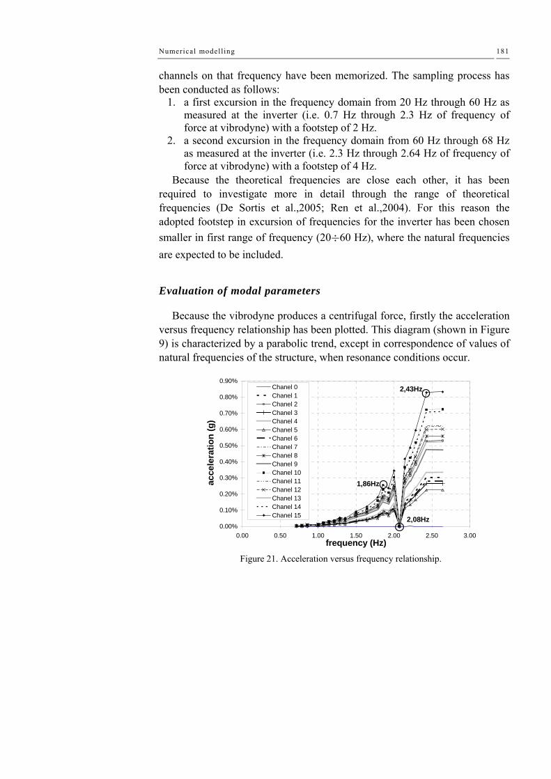
Numerical modelling 181
channels on that frequency have been memorized. The sampling process has been conducted as follows:
1. a first excursion in the frequency domain from 20 Hz through 60 Hz as measured at the inverter (i.e. 0.7 Hz through 2.3 Hz of frequency of force at vibrodyne) with a footstep of 2 Hz.
2. a second excursion in the frequency domain from 60 Hz through 68 Hz as measured at the inverter (i.e. 2.3 Hz through 2.64 Hz of frequency of force at vibrodyne) with a footstep of 4 Hz.
Because the theoretical frequencies are close each other, it has been required to investigate more in detail through the range of theoretical frequencies (De Sortis et al.,2005; Ren et al.,2004). For this reason the adopted footstep in excursion of frequencies for the inverter has been chosen smaller in first range of frequency (20÷60 Hz), where the natural frequencies are expected to be included.
Evaluation of modal parameters
Because the vibrodyne produces a centrifugal force, firstly the acceleration versus frequency relationship has been plotted. This diagram (shown in Figure 9) is characterized by a parabolic trend, except in correspondence of values of natural frequencies of the structure, when resonance conditions occur.
0.00%
0.10%
0.20%
0.30%
0.40%
0.50%
0.60%
0.70%
0.80%
0.90%
0.00 0.50 1.00 1.50 2.00 2.50 3.00frequency (Hz)
acce
lera
tion
(g)
Chanel 0Chanel 1Chanel 2Chanel 3Chanel 4Chanel 5Chanel 6Chanel 7Chanel 8Chanel 9Chanel 10Chanel 11Chanel 12Chanel 13Chanel 14Chanel 15 2,08Hz
1,86Hz
2,43Hz
Figure 21. Acceleration versus frequency relationship.

Chapter VI
182
The peak values of Fourier Spectra are amplified under conditions of
resonance, so it is possible to recognize the natural frequencies in correspondence of such peaks (Richardson, 1986; Richardson, 1999).
An example of the measured acceleration time histories is shown in Figure 10, together with the corresponding FFT transfer function.
-0.006
-0.004
-0.002
0.000
0.002
0.004
0.006
0.00 2.00 4.00 6.00 8.00 10.00 12.00time (sec)
acce
lera
tion(
g)
a: time history at 2,43Hz frequency, channel 8
0.0000
0.0010
0.0020
0.0030
0.0040
0.0050
0.0060
0.0070
0.0080
0.0090
0.00 2.00 4.00 6.00 8.00 10.0frequency (Hz)
acce
lera
tion
(g) Chanel 0 Chanel 1 Chanel 2
Chanel 3 Chanel 4 Chanel 5Chanel 6 Chanel 7 Chanel 8Chanel 9 Chanel 10 Chanel 11Chanel 12 Chanel 13 Chanel 14Chanel 15
b: FFT of signal at 2.43 Hz frequency Figure 22. An example of measured data and corresponding spectrum.
The evaluation of modal damping ξ has been carried out by means of half-
power band width method (Chopra, 2000).

Numerical modelling 183
The periods, frequencies and modal damping are presented for first three natural modes of vibration in Tab.5.1.
Period Frequency ξ
Sec Hz % Mode 1 0.537 1,86 1,15 Mode 2 0.481 2,08 2,96 Mode 3 0.412 2,43 1,38
Table IV. Dynamic properties.
Comparison among theoretical and experimental results
As it was expected, the experimental periods are sensitively different with respect to those deduced by the preliminary model, as shown in Table 6.1. This difference is due to the fact that the contribution offered by masonry infill walls to the system stiffness has not been considered in the numerical model. As expected these “non–structural” elements significantly increase the lateral stiffness, hence the measured periods are smaller than the theoretical ones.
Period (sec)
Numerical model
Experimental Test
Variation (%)
Mode 1 0.814 0.537 34.0 Mode 2 0.783 0.481 38.6 Mode 3 0.652 0.412 36.8
Table V. Theoretical and experimental periods.

Chapter VI
184
6.5 MODELLING OF THE MASONRY INFILL RC STRUCTURE
Numerical model of RC bare frame structure
Geometry
Numerical model of structure under investigation has been carried out by means of well know non linear finite element program SAP 2000 ver. 9.0.9; beams and colums has been modeled as frame elements. The foundation has been simulated by neglecting any degree of freedom to the node belonging to the foundation floor. The first and second rigid-floors have been modeled applying to the node of the two floors a diagrfahm constrains. The dimensions of the structural elements come from the relief of the geometry of the structure. In particular, all columns have a square cross section whith the side of 30cm and longitudinal reinforcement of 4Ø14 for each side. Perimetral beams have a rectangular cross section of 20x60cm at the first floor, and 15x60cm at the second floor.
The staircase has been modeled as a frame element with a rectangular cross section having the base of 90 cm and the height of 15cm, in which the steps has considered as external load. Materials
The choice of materials properties has been done according to results of preliminary characterization tests on the structural elements. In particular some experimentaltests has been conducted on the masonry blocks of infill walls.
For the concrete elements has been supposed a characteristic strength value (Rck) of 200 kg/cm2 with an average value of Rck/0.75 = 265 kg/cm2, the Young modulus, taking in account the ancientness of the structure, has been assumed equal to 300.000 kg/cm2; and for the steel has been assumed the steel grade FeB44k, having an average strength of 4890 kg/cm2.

Numerical modelling 185
These assumption find the existence on the materials properties of the first tested structure of the ILVA-IDEM project. For the masonry elements, in particular, has been assumed a young modulus of clay bloks and cement and lapillus blocks respectively equal to: Elat=49.500 kg/cm2 and Elap=10.500 kg/cm2. Push-over analysis of RC bare frame structure
Starting from the cited data, a 3D FEM model has been carried out of the bare frame structure without the presence of infill walls.
A pushover analysis has been conducted by the application of a lateral force system simulating an inverted triangular load distribution; for each floor the force has been applied in the mass centroid.
Numerical analysis results have showed the formation of column-type collapse mechanism with the formation of plastic hinges at both the ends of columns of the first floor and in correspondence of the staircase.
The structure reach a peack strength of about 1600 kN for a lateral displacement equal to 3,00 cm. The following figures showed the numerical model and results in terms of collapse mechanism and in terms of base shear versus lateral displacement.
Figure 23. 3D–FEM model of bare frame structure.
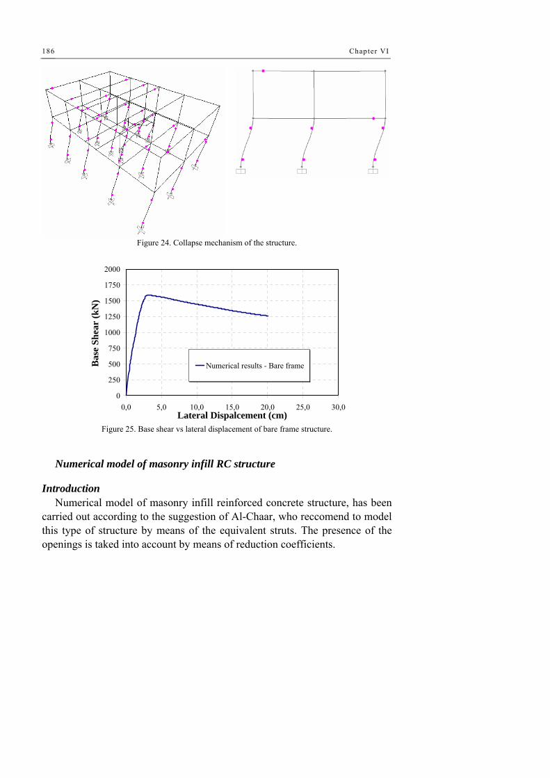
Chapter VI
186
Figure 24. Collapse mechanism of the structure.
0
250
500
750
1000
1250
1500
1750
2000
0,0 5,0 10,0 15,0 20,0 25,0 30,0Lateral Dispalcement (cm)
Bas
e Sh
ear
(kN
)
Numerical results - Bare frame
Figure 25. Base shear vs lateral displacement of bare frame structure.
Numerical model of masonry infill RC structure
Introduction Numerical model of masonry infill reinforced concrete structure, has been
carried out according to the suggestion of Al-Chaar, who reccomend to model this type of structure by means of the equivalent struts. The presence of the openings is taked into account by means of reduction coefficients.

Numerical modelling 187
In the following table are reported the fundamental values of strength, stiffness and geometrical dimension of the different equivalent struts. The legend of different parameters indicated in the table is here reported.
Legend: fwv: compressive strength of the masonry; Ec: Young modulus of the concrete; Ew: Young modulus of the masonry; Ip: inertia of the columns; hw: height of the infill panels; h: inter-story; lw: length of the infill panels; tw: thikness of the infill panels; dw: length of equivalent struts; θstrutt: slope angle of the struts; λ: stiffness parameters between the frame and the infill walls; bw: depth of the equivalent struts; Aaper: openings area; Apann: area of the infills; Vss: shear strength of the infills; Vdt: diagonal strength; Vc: strength in compression of the infills; lcolum: rigid end-offset along the column; smax: ultimate displacement of the strut; selast: maximum elastic displacement of the strut; breduct: reducted depth of compressed diagonal; lbeam: rigid end-offset along the beam.

Chapter VI
188
E600 es E600 in E510 es E510 in O 600 es O 600 in O 510 es O 510 in tramezzi
fwv 66,0 14,0 66,0 14,0 66,0 14,0 66,0 14,0 14,0fvk0 2,0 1,0 2,0 1,0 2,0 1,0 2,0 1,0 1,0Ec 300000 300000 300000 300000 300000 300000 300000 300000 300000Ew 49500 10500 49500 10500 49500 10500 49500 10500 10500Ip 67500 67500 67500 67500 67500 67500 67500 67500 67500hw 390 390 390 390 390 390 390 390 410H 485 485 485 485 485 485 485 485 435lw 600 600 510 510 600 600 510 510 600tw 10 10 10 10 10 10 10 10 10Area pil 900 900 900 900 900 900 900 900 900Aaper 22077 22077 22077 22077 44154 44154 3200 3200 16800Apann 234000 234000 198900 198900 234000 234000 198900 198900 234000dw 716 716 642 642 716 716 642 642 727θ rad 0,5764 0,5764 0,6528 0,6528 0,5764 0,5764 0,6528 0,6528 0,5995λ 0,0278 0,0189 0,0282 0,0191 0,0278 0,0189 0,0282 0,0191 0,0187λh 5,31 3,60 5,38 3,65 5,31 3,60 5,38 3,65 3,20Aap/Apann 0,09 0,09 0,11 0,11 0,19 0,19 0,02 0,02 0,07bw (a) 64 75 57 67 64 75 57 67 80Vdt 17088 8544 14107 7053 14389 7195 16565 8283 8882Vss 15024 3239 13309 2798 13051 2750 15484 3251 3392Vc 36226 8973 31395 7776 30505 7556 36866 9132 9925lcolum 50 38 30 35 28 32 35 41 43qstrut 0,4493 0,4816 0,5745 0,5605 0,5091 0,4972 0,5599 0,5431 0,4953Val-chaar 15024 3239 13309 2798 13051 2750 15484 3251 3392smax 3,75 3,87 3,60 3,72 3,78 3,84 3,69 3,75 3,75selast 1,25 1,29 1,20 1,24 1,26 1,28 1,23 1,25 1,25b 0,998 4,631 1,127 5,361 1,149 5,454 0,969 4,614 4,422R1 0,85 0,85 0,83 0,83 0,72 0,72 0,97 0,97 0,89breduct 55 64 48 56 46 54 56 65 71drift 1,39 1,45 1,43 1,46 1,44 1,46 1,45 1,46 1,42apilastr 50 38 30 35 28 32 35 41 43
atrave 50 59 39 46 42 50 46 54 63 Table VI. Imput data.
Constitutive law of the diagonal struts
In order to evaluate the displacement parameter of constitutive law of
different infill walls, the table 7-9 of FEMA 356 has been considered. The shape of constitutive law is following represented:

Numerical modelling 189
Figure 26. Constitutive law of equivalent struts.
In which Rstrut is the strength of each one panel and it is a function of the
mechanical properties of the materials and of openings’ dimension. For each panel is possibile to determine the ratio between Linf/hinf, varying
from 1.30 to 1.53, and the values of β is possible to determine the floor drift.
ine
fre
VV
=β
In which Vfre is the shear strength of the bare frame, while Vine is the shear strength of the infill wall (β is ever bigger than 1.30). Now is possible evaluate the displacement along the eccentric diagonal by multiply this value for hinf and for cos(θstrut). Finite element numerical model
Figure 27. 3D numerical model of masonry infilled RC frames.

Chapter VI
190
Starting from the built numerical model of RC bare frame structure, the tested structure with the infill walls has been modeled according to the indication of Al Chaar (2002). In particular, the infills have been modeled by means of the equivalent struts.
Figure 28. Lateral view of numerical model.
Numerical results
Figure 29. Collapse mechanism.
The deformate shape denote that the collapse mechanism interest the first
floor elements (column and infill walls) with the formation of the plastich

Numerical modelling 191
hinge at both the ends of the columns and the diagonal cracks in the infill due to the shear force.
Figure 30. Comparison between numerical and experimental collapse mechanism – east side.
Figure 31. Comparison between numerical and experimental collapse mechanism – west side.
Comparison between numerical/experimental results
The comparison between numerical and experimental results is done in terms of strength, stiffness, collapse mechanism and dissipated energy. From this comparison is possible Collapse mechanism
Numerical model results, according to the experimental data, denote a collapse mechanism that interest the first floor with the development of
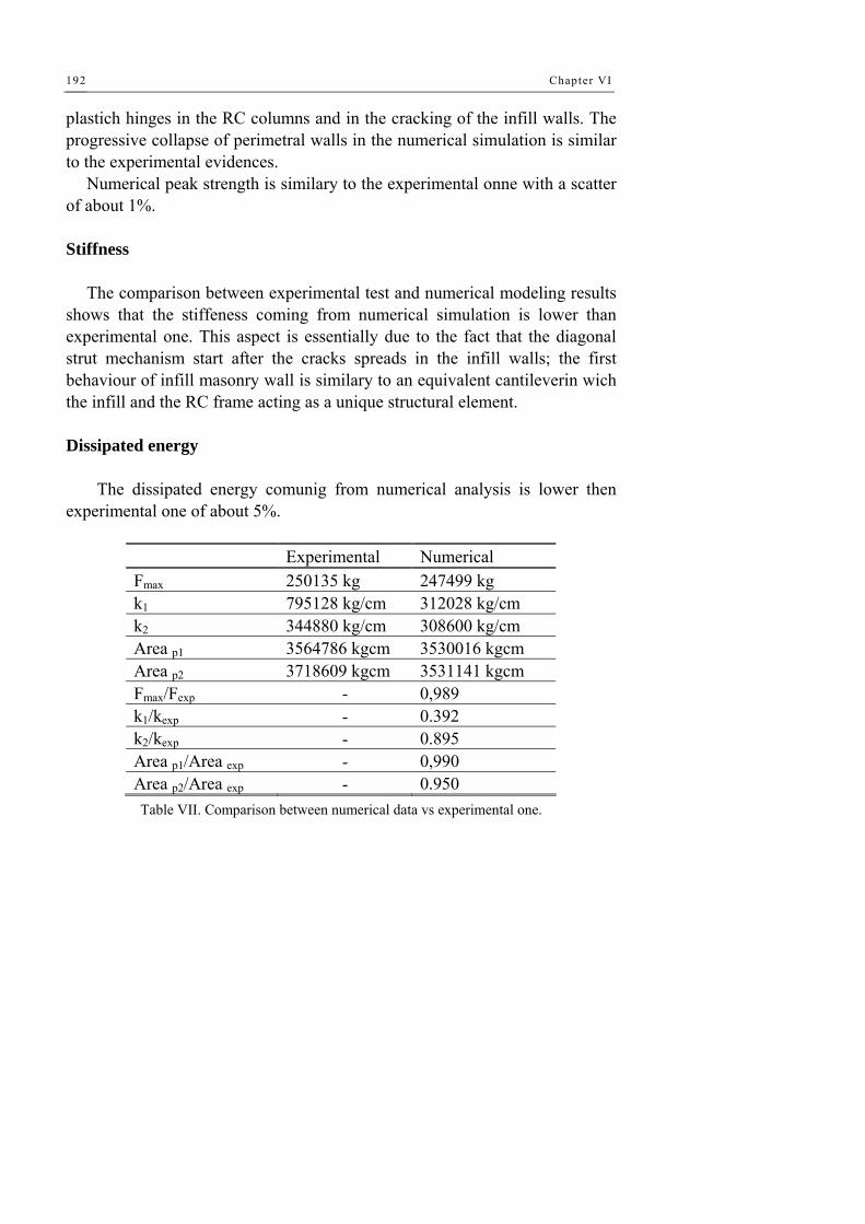
Chapter VI
192
plastich hinges in the RC columns and in the cracking of the infill walls. The progressive collapse of perimetral walls in the numerical simulation is similar to the experimental evidences.
Numerical peak strength is similary to the experimental onne with a scatter of about 1%. Stiffness
The comparison between experimental test and numerical modeling results shows that the stiffeness coming from numerical simulation is lower than experimental one. This aspect is essentially due to the fact that the diagonal strut mechanism start after the cracks spreads in the infill walls; the first behaviour of infill masonry wall is similary to an equivalent cantileverin wich the infill and the RC frame acting as a unique structural element. Dissipated energy
The dissipated energy comunig from numerical analysis is lower then experimental one of about 5%.
Experimental Numerical Fmax 250135 kg 247499 kg k1 795128 kg/cm 312028 kg/cm k2 344880 kg/cm 308600 kg/cm Area p1 3564786 kgcm 3530016 kgcm Area p2 3718609 kgcm 3531141 kgcm Fmax/Fexp - 0,989 k1/kexp - 0.392 k2/kexp - 0.895 Area p1/Area exp - 0,990 Area p2/Area exp - 0.950 Table VII. Comparison between numerical data vs experimental one.

Numerical modelling 193
0
500
1000
1500
2000
2500
3000
0,0 2,5 5,0 7,5 10,0 12,5 15,0 17,5 20,0Roof Dispalcement (cm)
Bas
e Sh
ear (
kN)
Figure 32. Base shear vs lateral displacement -second floor response.
0
500
1000
1500
2000
2500
3000
0,0 2,5 5,0 7,5 10,0 12,5 15,0 17,5 20,01st Floor displacement (cm)
Bas
e Sh
ear (
kN)
Figure 33. Base shear vs lateral displacement -first floor response.
The seguent figure shows the different contribution offered by the several
structural and “non structural” elements to the strength of the structure. It is possible to see how the stircase and infill walls had a considerable influence on the structural response of the structure.
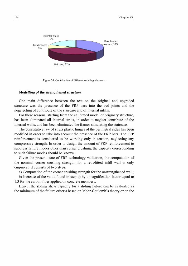
Chapter VI
194
External walls; 19%
Inside walls; 9%
Staircase; 35%
Bare frame structure; 37%
Figure 34. Contribution of different resisting elements.
Modelling of the strengthened structure
One main difference between the test on the original and upgraded structure was the presence of the FRP bars into the bed joints and the negelecting of contribute of the staircase and of internal infills.
For these reasons, starting from the calibrated model of originary structure, has been eliminated all internal struts, in order to neglect contribute of the internal walls, and has been eliminated the frames simulating the staircase.
The constitutive law of struts plastic hinges of the perimetral sides has been modified in order to take into account the presence of the FRP bars. The FRP reinforcement is considered to be working only in tension, neglecting any compressive strength. In order to design the amount of FRP reinforcement to suppress failure modes other than corner crushing, the capacity corresponding to such failure modes should be known.
Given the present state of FRP technology validation, the computation of the nominal corner crushing strength, for a retrofitted infill wall is only empirical. It consists of two steps:
a) Computation of the corner crushing strength for the unstrengthened wall; b) Increase of the value found in step a) by a magnification factor equal to
1.3 for the carbon fiber applied on concrete members. Hence, the sliding shear capacity for a sliding failure can be evaluated as
the minimum of the failure criteria based on Mohr-Coulomb’s theory or on the
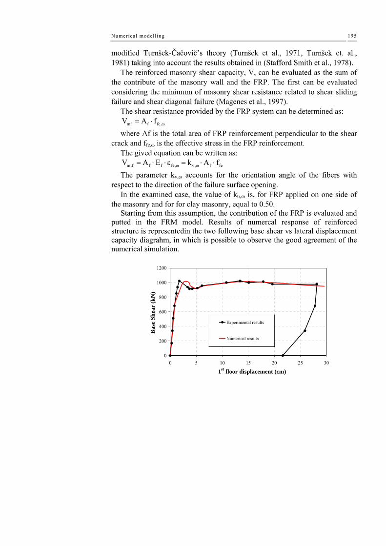
Numerical modelling 195
modified Turnšek-Čačovič’s theory (Turnšek et al., 1971, Turnšek et. al., 1981) taking into account the results obtained in (Stafford Smith et al., 1978).
The reinforced masonry shear capacity, V, can be evaluated as the sum of the contribute of the masonry wall and the FRP. The first can be evaluated considering the minimum of masonry shear resistance related to shear sliding failure and shear diagonal failure (Magenes et al., 1997).
The shear resistance provided by the FRP system can be determined as: mf f fe,V A f ω= ⋅
where Af is the total area of FRP reinforcement perpendicular to the shear crack and ffe,ω is the effective stress in the FRP reinforcement.
The gived equation can be written as: m,f f f fe, , f feV A E k A fω ν ω= ⋅ ⋅ε = ⋅ ⋅
The parameter kv,ω accounts for the orientation angle of the fibers with respect to the direction of the failure surface opening.
In the examined case, the value of kυ,ω is, for FRP applied on one side of the masonry and for for clay masonry, equal to 0.50.
Starting from this assumption, the contribution of the FRP is evaluated and putted in the FRM model. Results of numercal response of reinforced structure is representedin the two following base shear vs lateral displacement capacity diagrahm, in which is possible to observe the good agreement of the numerical simulation.
0
200
400
600
800
1000
1200
0 5 10 15 20 25 30
1st floor displacement (cm)
Bas
e Sh
ear
(kN
)
Experimental results
Numerical results

Chapter VI
196
0
200
400
600
800
1000
1200
0 5 10 15 20 25 30
2nd floor displacement (cm)
Bas
e Sh
ear
(kN
)
Experimental results
Numerical results
Figure 35. Numerical simulation of the upgraded structure response.

197
Chapter VII Conclusion remarks
7.1 CONCLUDING REMARKS AND FURTHER DEVELOPMENTS
The present thesis work has been finalised to the study of composite materials used for the seismic upgrading of existing RC structures. The choice of this material, which is really innovative in the field of seismic engineering, is justified by high strength and its high flexibility of use.
After a wide survey carried out on the most common seismic protection systems and the study of related analysis methodologies, the attention has been focused on the numerical and experimental study of real RC structures reinforced by means of FRP in form of carbon fiber. The carbon fiber material is characterised by a high strength and an elastic modulus comparable to the steel one.
Firstly, a numerical study finalised to prediction of experimental behaviour of an existing RC bare frame structure has been done. After this first phase an experimental test has been conducted on the real structure showing a non-ductile behaviour by forming a column-type collapse mechanism and a loss redistribution capacity.
The obtained results allowed the definition of a seismic upgrading design having the main purpose to increase the strength, stiffness and lateral displacement capacity of the structure and to change the collapse mechanism from a column-type to a beam-type. The reinforcement consists in the

Chapter VII
198
application on the damaged structure of longitudinal FRP strips, along the columns, and in the application of transversal sheets.
The seismic performance of the upgraded structure demonstrated the validity of the designed reinforcement. In particular, as it can be seen in Figure 1, the strength of the FRP-rehabilitated structure is measured to be 86% larger than the initial value if the positive envelope is considered and 100% larger if the negative envelope curve is contemplated.
Analogously, the lateral top-displacement capacity is increased of about 100% of the initial value irrespective of the sign of the imposed displacement (strength degradation exhibited by the FRP-strengthened structure is considered negligible for both positive and negative loading direction up to a top-displacement of about 250 mm).
0
20
40
60
80
100
120
140
160
0.00 0.05 0.10 0.15 0.20 0.25 0.30Top Displacement (m)
Bas
e Sh
ear (
kN)
FRP-Strengthened
Un-strengthened
NegativeEnvelope
Positive Envelope
Figure 1: Comparison of the initial vs. FRP-rehabilitated structure response.
Also, it has been observed that the structural behaviour of reinforced
structure is characterized by favourable collapse mechanisms, characterized by the progressive yielding of beams and successive plastic hinge development in the end of the columns.
This experience demonstrated the validity of FRP applications in the case of existing structure for the seismic refurbishment; in fact, the FRPs are generally considered as a valid alternative in the case of the local repairing, because it increases the strength of a column section, the ductility of a beam-

Conclusion remarks 199
to-column node, or to keep down the deformability of an ancient beam for satisfy the serviceability limit states. In this case it is evident the FRPs can be applied as global application on RC structures.
It is also important to highlight the good agreement obtained in the numerical modelling; by an accurate calibration process it is possible to evaluate the benefits of FRP materials on the structures.
0
10
20
30
40
50
60
70
80
90
0.00 0.05 0.10 0.15 0.20 0.25 0.30Displacement (m)
Bas
e Sh
ear (
kN)
Experimental - First FloorExperimental - Second FloorNumerical - First FloorNumerical - Second Floor
0
20
40
60
80
100
120
140
160
0.00 0.05 0.10 0.15 0.20 0.25 0.30Top Displacement (m)
Bas
e Sh
ear (
kN)
Experimental positive envelope
Experimental negative envelope
Numerical
Figure 2: Comparison of the numerical analysis vs experimental results response for both initial and FRP-rehabilitated structures.
The second part of the experimental activity focused on masonry-infilled
RC framed building. These type of structures appear to be strongly affected by the presence of the walls and their interaction with infilling frames, when they are in tight contact.
This effect can produce large differences with theoretical models prediction based solely on the frame contribution. Results of the experimental dynamic identification of the investigated building show that neglecting the infill-walls contribution to the stiffness matrix computation led to an overestimation of the natural periods of vibration ranging from 34% to 39% depending on the vibration mode.
Results of the static inelastic tests shows that the strength of the building was increased up to 2.5 times the strength that could be expected on the basis of the bare RC frame (i.e. neglecting the wall contribution, as it is shown in Fig. 2). On the other hand, test results show that the brittle response of the “non structural” masonry infill walls produced strength and stiffness degradation, rapidly leading to the deterioration of walls contribution. But,
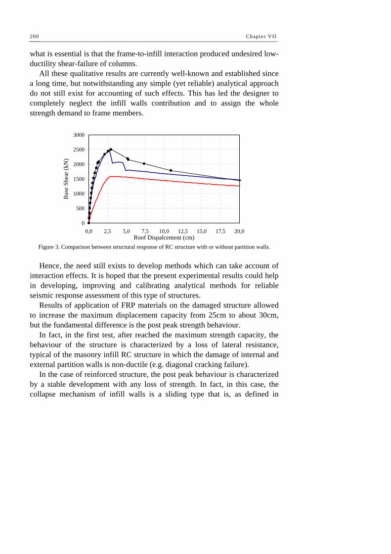
Chapter VII
200
what is essential is that the frame-to-infill interaction produced undesired low-ductility shear-failure of columns.
All these qualitative results are currently well-known and established since a long time, but notwithstanding any simple (yet reliable) analytical approach do not still exist for accounting of such effects. This has led the designer to completely neglect the infill walls contribution and to assign the whole strength demand to frame members.
0
500
1000
1500
2000
2500
3000
0,0 2,5 5,0 7,5 10,0 12,5 15,0 17,5 20,0Roof Dispalcement (cm)
Bas
e Sh
ear (
kN)
Figure 3. Comparison between structural response of RC structure with or without partition walls. Hence, the need still exists to develop methods which can take account of
interaction effects. It is hoped that the present experimental results could help in developing, improving and calibrating analytical methods for reliable seismic response assessment of this type of structures.
Results of application of FRP materials on the damaged structure allowed to increase the maximum displacement capacity from 25cm to about 30cm, but the fundamental difference is the post peak strength behaviour.
In fact, in the first test, after reached the maximum strength capacity, the behaviour of the structure is characterized by a loss of lateral resistance, typical of the masonry infill RC structure in which the damage of internal and external partition walls is non-ductile (e.g. diagonal cracking failure).
In the case of reinforced structure, the post peak behaviour is characterized by a stable development with any loss of strength. In fact, in this case, the collapse mechanism of infill walls is a sliding type that is, as defined in

Conclusion remarks 201
literature, pseudo-ductile collapse behaviour. The application of FRP in the bed joint guaranteed the necessary tensile strength to the walls in order to modify the collapse behaviour passing from a diagonal cracking type to a sliding type.
By a directly comparison (Figure 4) between the experimental response curves of each tests is possible to observe that the strength of reinforced structure is smaller than the un-reinforced one. This can appear as a contradiction or a failure of the intervention, but it is essentially due to the absence, in the second test, of the contribute of the staircase and of the internal walls serially damaged after the first test and not repaired.
-2000
-1500
-1000
-500
0
500
1000
1500
2000
2500
-30 -25 -20 -15 -10 -5 0 5 10 15 20 25 30
Lateral Displacement (cm)
Bas
e Sh
ear (
kN)
First Test
Second Test
Figure 4: Comparison of structural response in terms of base shear – lateral displacement.


References
Abdalla, H.A. and Mostafa, H., “Strengthening of Masonry Walls To Resist In-Plan And Out-of-Plane Loads: Experimental Studies”, Structural Composites for Infrastructures Applications, Aswan, Egypt, December, 2002.
Abdul Rahman, B. (2005): “Out-Of-Plane GFRP Strengthening of Natural Masonry
Abrams, D.P., “Seismic Rehabilitation Technologies For Masonry Walls”, The National Symposium on Compressive Force Protection Sponsored by the Society of American Military Engineers. The citadel, Charleston, sc, November 2001.
ACI 440 M (2005): “Guide for the Design and Construction of Externally Bonded FRP Systems for Strengthening Unreinforced Masonry Structures”, Draft of the State-of-the Art Report on externally bonded Fiber Reinforced Plastic (FRP) Reinforcement for Masonry Structures.
ACI 440.1R-01 (2001):”Guide for the design and construction of concrete reinforced with FRP bars”, ACI committee report ISBN 0-87031-C32-1.
ACI 530-95 / ASCE 4-95 / TMS 402-95 (1995):”Building Code requirements for masonry structures”.
ACI Committee 440 (1996). State-of-the-art report on FRP for concrete structures, ACI440R-96, Manual of Concrete Practice, American Concrete Institute, Farmington Hills, MI.
ACI Committee 530, (1990), “State-of-The-Art Report on Ferrocement “, ACI Manual of Concrete Practice, Part 5.
Aiello, M.: Sciolti, M.: Pecce, M., (2003):“Experimental Investigation on Bond between FRP Sheets and Natural Masonry Blocks”, Proceedings of the International Conference Structural Faults and Repair, 1-3 July, London UK.
Albert, I. Micheal, Elwi, E. Alaa; and Cheng, J. J. Roger, (2001): “Strengthening of Unreinforced Masonry Walls Using FRPs”, J. Comp. for
References
Constr., ASCE, No. 2, 76-84.
Bousias S., Spathis A.-L., Fardis M.N. (2004). Seismic retrofitting of columns with lap-splices through CFRP jackets. Proceedings of the 13th World Conference on Earthquake Engineering, Vancouver, B.C., Canada, August 1-6, CD-ROM, paper n. 765.
Buda G., Buonsanti M., Santini A., "Valutazione sperimentale delle caratteristiche dinamiche delle torri-faro dell’aeroporto dello stretto”, Ingegneria sismica vol.3 (2004) 19–29
Chopra, A. (2000). Dynamics of structures: Theory and Applications to Earthquake Engineering, Prentice Hall
Chung Y.S., Lee D.H., Park C.K., Song H.W. (2004). Curvature variation of earthquake experienced RC bridge pier in the plastic hinge region. Proceedings of the 13th World Conference on Earthquake Engineering, Vancouver, B.C., Canada, August 1-6, CD-ROM, paper n. 2097.
Concrete Society Technical Report 55 (2000). Design guidance for strengthening concrete structures using fibre composites materials. The Concrete Society, Crowthorne, UK.
De Lorenzis L., Nanni A., and La Tegola A., “Flexural and Shear Strengthening of Reinforced Concrete Structures with Near Surface Mounted FRP Rods,” Proceedings of Third International Conference on Advanced Composite Materials in Bridges and Structures, Ottawa, Canada, August 2000, pp. 521-528.
De Lorenzis L.: Nanni A., (2004):“The International Workshop on Preservation of Historical Structures with FRP Composites”, Final Report Submitted to National Science Foundation (NSF) Lecce, Italy, June 9-10 http://www.cies.umr.edu
De Sortis A., Antonacci E., Vestroni F., "Dynamic identification of a masonry building using forced vibration tests”, Engineering Structures vol.27 (2005) 155–165
Della Corte, G.; Barecchia, E.; Mazzolani, F.M., (2004). “Seismic upgrading of existing RC structures using FRP: a GLD study case. Proceedings of the First International Conference on Innovative Materials and Technologies for Construction and Restoration (IMTCR), Lecce, Italy.

References
Della Corte, G.; Barecchia, E.; Mazzolani, F.M., (2005a). “Seismic upgrading of RC structures by means of composite materials: a state-of-the-art review,” Proceedings of the COST C12 Final Conference: Improving building’s structural quality by new technologies, Innsbruck, Austria.
Della Corte, G.; Barecchia, E.; Mazzolani, F.M., (2005b). “Seismic upgrading of RC buildings by FRP: full scale tests of a real structure,” Journal of Materials in Civil Engineering, ASCE, accepted for publication.
Della Corte, G.; Barecchia, E.; Mazzolani, F.M., (2005c). “Seismic strengthening of RC buildings by means of FRP: physical testing of an existing structure,” Proceedings of the 4th Middle East Symposium on Structural Composites for Infrastructure Applications, Alexandria, Egypt.
Design”, Textbook and design reference, ISBN 0-13-562026-0, Sponsored by Brick Institute of America National Concrete Masonry Association published by Prentice-Hall.
Drydale, G.; Hamid, A. and Baker, L., “Masonry Structures Behavior and Design”, second edition, the masonry society, Boulder, Colordo, 1999.
Drysdale, R.: Hamid, A.: Baker, L., (1994):“Masonry Structures Behavior and ECM, (2005), “Egyptian Code for Masonry Design & Construction Principles” Housing & Building Research Centre (HBRC), Cairo.
El-Amoury T., Ghobarah A. (2002). Seismic rehabilitation of beam-column joint using GFRP sheets. Engineering Structures, 24: 1397-1407.
ElGawady, M., Lestuzzi, P., Badoux, M., (2003): “Dynamic tests on URM walls before and after upgrading with composites”, Exper. Rep., Pub. No. 1, IMAC, ENAC, EPFL, Switzerland.
El-Hefnawy, A.A., Sabrah, T.B. and Hodhod, O.A., “Upgrading Load Bearing Walls Using Ferrocement Overlays”, International Conference: Future Vision and Challenges for Urban Development, Cairo, Egypt, December, 2004.
Erdem, I., Akyuz, U., Ersoy, U., Ozcebe, G. (2004). “Experimental and analytical studies on the strengthening of RC frames”. Proc. of the 13th World Conference on Earthquake Engineering, (CD-Rom, paper n. 673), Vancouver, B.C., Canada, August 1-6.
Erol, G., Yuksel, E., Saruhan, H., Sagbas, G., Tuga, P.T., Karadogan, H.F.

References
(2004). “A complementary experimental work on brittle partitioning walls and strengthening by carbon fibers”. Proc. of the 13th World Conference on Earthquake Engineering, (CD-Rom, paper n. 979), Vancouver, B.C., Canada, August 1-6.
ESS No. 1108, (2001), “Sand For Masonry Mortars”, Egyptian Standard Specification, Ministry of Industry, Cairo. 12- ESS No. 373, (1991), “Portland Cement, Ordinary and Rapid Hardening”, Egyptian Standard Specification, Ministry of Industry, Cairo.
Eurocode 2, (2004). “EN 1992-1-1, Design of concrete structures - Part 1.1: General rules and rules for buildings,” CEN, Bruxelles.
FEMA 356, (2000). “Prestandard and Commentary for the Seismic Rehabilitation of Buildings” Washington D.C., Federal Emergency Management Agency, November.
fib (CEB-FIP), (2001). Bulletin n.14 (Task Group 9.3), “Externally bonded FRP reinforcement for RC structures”, Sprint-Digital-Druck, Stuttgard.
Fyfe E.R., Duane J. Gee Peter Milligan (1998). Composite materials for rehabilitation of civil structures and seismic applications. Proceedings of the Second International Conference on Composites in Infrastructure, Eds.: Saadatmanesh and M.R. Ehsni, Tucson, AZ.
Garevski M., Hristovski V., Talaganov K., Stojmanovska M. (2004). Experimental investigations of 1/3-scale RC frame with infill walls building structures. Proceedings of the 13th World Conference on Earthquake Engineering, Vancouver, B.C., Canada, August 1-6, CD-ROM, paper n. 772.
Ghobarah A., Khalil A.A: (2004). Seismic rehabilitation of reinforced concrete walls using fibre composites. Proceedings of the 13th World Conference on Earthquake Engineering, Vancouver, B.C., Canada, August 1-6, CD-ROM, paper n. 3316.
Ghobarah, A., Said, A. (2001). “Seismic rehabilitation of beam-column joints using FRP laminates”. Journal of Earthquake Engineering, 5(1), 113-129.
Ghobarah, A.: Galal, K., (2004):“Out-of-Plane Strengthening of Unreinforced URM walls using composites”, 4th Int. Conf. ACMBS, Calgary, Canada.

References
Hadad, H.S.; Mahmoud, A.S. and Abou Elmagd, S.A., “Behavior of Strengthened Masonry Shear Walls With Openings Using GFRP”, Structural Composites for Infrastructures Applications, Aswan, Egypt, December, 2002.
Hamid, A., Mahmoud, A., Abo El Maged, S., (1994): “Strengthening and repair of unreinforced masonry structures: state-of-the-art”, 10th IB2MaC, Calgary, Canada, 485-497.
Hamoush, S.: Mlakar, P.: Bastos, A.: Costa, A., (2003): “The Shear Strength of Fiber Reinforced Masonry Walls”, Proceedings of the International Conference Structural Faults and Repair 1-3 July, London UK.
ICBO, (2001): “Acceptance criteria for concrete and reinforced and unreinforced masonry strengthening using fiber-reinforced polymer (FRP)”: AC125, Whittier, Ca., USA.
Ilki A., Tezcan A., Koc V., Kumbasar N. (2004). Seismic retrofit of non-ductile rectangular reinforced concrete columns by CFRP jacketing. Proceedings of the 13th World Conference on Earthquake Engineering, Vancouver, B.C., Canada, August 1-6, CD-ROM, paper n. 2236.
Johnson G.P., Robertson I.N. (2004). Retrofit of slab-column connections using CFRP. Proceedings of the 13th World Conference on Earthquake Engineering, Vancouver, B.C., Canada, August 1-6, CD-ROM, paper n. 142.
Klingner, R. E., & Bertero, V.V., (1976). “Infilled frames in earthquake resistant construction”. Report EERC 76-32, Earthquake Engineering Research Center, December.
Klingner, R. E., & Bertero, V.V., (1978). “Earthquake resistance of infilled frames”. Journal of the Structural Division, vol.104, n. ST6, pp. 973-989.
Lee Y.-T., Kim S.-H., Hwang H.-S., Lee L.-H. (2004). Evaluation on the shear strengthening effect of RC columns with carbon fibre sheets. Proceedings of the 13th World Conference on Earthquake Engineering, Vancouver, B.C., Canada, August 1-6, CD-ROM, paper n. 1369.
Li, J., Bakoss, S.L., Samali, B.,Ye, L. (1999). “Reinforcement of concrete beam-column connections with hybrid FRP sheet”. Composite Structures, (47), 805-812.

References
Mazzolani F.M., Della Corte G., Calderoni B., De Matteis G., Faggiano B., Panico S., Dolce M., Landolfo R., Spina D., Valente C. (2004b). The ILVA-IDEM Project: full scale pushover test on an existing RC structure – Part I: experimental results. Proceedings of the XI Congress of the Italian National Association of Earthquake Engineering (ANIDIS 2004), Genova, Italy, 25-29 January, CD-ROM.
Mazzolani, F.M., Della Corte, G., Faggiano, B. (2004). “Seismic upgrading of RC buildings by means of advanced techniques: the ILVA-IDEM project.” Proc. of the 13th World Conference on Earthquake Engineering, (CD-Rom, paper n. 2703), Vancouver, B.C., Canada, August 1-6.
Mazzolani, F.M., Della Corte, G., Faggiano, B. (2004a). “Seismic upgrading of RC buildings by means of advanced techniques: the ILVA-IDEM project” Proc. of the 13th World Conference on Earthquake Engineering, (CD-Rom, paper n. 2703), Vancouver, B.C., Canada, August 1-6.
Mazzoni, S., McKenna, F., Fenves, G.L., (2005). OpenSEES Commad Language Manual. Open System for Earthquake Engineering Simulation.
Mosalam, K.M., “Retrofitting of Unreinforced Masonry Walls Using Glass Fiber Reinforced Polymer Laminates”, International Conference: Future Vision and Challenges for Urban Development, Cairo, Egypt, December, 2004.
Mosallam, A.S. (2000). “Strength and ductility of reinforced concrete moment frame connections strengthened with quasi-isotropic laminates”. Composites: Part B, (31), 481-497.
Panagiotakos, T. B., & Fardis, M.N., (1994). “Proposed non-linear strut models for infill panels”. 1st Year Progress Report of HCM-PREC8, University of Patras.
Panagiotakos, T.B.; Fardis, M.N. (2001). “Deformations of RC members at yielding and ultimate,” ACI Structural Journal, V. 98, No. 2, pp. 135-148.
Pantelides, C.P., Duffin, J.B., Reaveley, L.D. (2004). “Design of FRP jackets for seismic strengthening of bridge T-joints” Proc. of the 13th World Conference on Earthquake Engineering, (CD-Rom, paper n. 3127), Vancouver, B.C., Canada, August 1-6.
Park, R.; Paulay, T., 1975. “Reinforced Concrete Structures”. New York, John

References
Wiley & Sons.
Parvin, A., Granata, P. (2000). “Investigation on the effects of fiber composites at concrete joints”. Composites: Part B, (31), 499-509.
Pavese A., Bolognini D., Peloso S. (2004). Seismic behaviour of RC hollow section bridge piers retrofitted with FRP. Proceedings of the 13th World Conference on Earthquake Engineering, Vancouver, B.C., Canada, August 1-6, CD-ROM, paper n. 2831.
Piyong, Y.: Silva, P.: Nanni, A., (2003): “Flexural Strengthening of Concrete Slabs by a Three-stage Prestressing FRP System Enhanced with the Presence of GFRP Anchor Spikes”, Proceedings of CCC 2003 - Composites in Construction International Conference, 16-19 September, University of Calabria Rende (CS), Italy. http://campus.umr.edu/rb2c/research/2003/03-46.pdf
Popovics S. (1973). Numerical approach to the complete stress-strain relation for concrete. Cement and Concrete Research, 3(5), 583-599.
Priestley, M.J.N.; Seible, F., (1995). “Design of seismic retrofit measures for concrete and masonry structures”. Construction and Building Materials, V. 9, No. 6, pp. 365-377.
Prota A., Nanni A., Manfredi G., Cosenza E. (2003). Capacity Assessment of RC subassemblages upgraded with CFRP. Journal of Reinforced Plastic and Composites, vol.22, n. 14, pp. 1287-1304(18).
Prota, A., Nanni, A., Manfredi, G., Cosenza, E. (2004). “Selective upgrade of under-designed RC beam-column joints using CFRP”. ACI Structural Journal, September-October, vol. 101, n.5.
Prota, A., Nanni, A., Manfredi, G., Cosenza, E. (2004a). “Selective upgrade of under-designed RC beam-column joints using CFRP.” ACI Structural Journal, September-October, vol. 101, n.5.
Prota, A.; Nanni, A.; Manfredi, G.; Cosenza, E., (2004b). “Capacity assessment of RC subassemblages upgraded with CFRP,” Journal of Reinforced Plastics and Composites, V. 22, No. 14, pp. 1287-1304.
Ren Wei-Xin, Zong Zhou-Hong “Output-only modal parameter identification of civil engineering structures”, Structural Engineering and Mechanics, Vol. 17, No. 3-4 (2004)

References
Retrofitted with FRP Overlays”, Journal of Composites for Construction ASCE, 1(1), pp 17-25. http://www.u.arizona.edu/~ehsani/Publications.htm
Richardson M.H., “Structural Dynamics Measurements”, Spectral Dynamics – April 11-16, 1999
Richardson M.H.,“Global frequency & damping estimates from frequency response measurements”, 4rd IMAC Conference, Los Angeles, CA February, 1986
Schlick, B.M., Breña, S.F. (2004). “Seismic rehabilitation of reinforced concrete bridge columns in moderate earthquake regions using FRP composites”. Proc. of the 13th World Conference on Earthquake Engineering, (CD-Rom, paper n. 508), Vancouver, B.C., Canada, August 1-6.
Schwegler, G., (1994): “Masonry construction strengthened with fiber composites in seismically endangered zones”, 10th ECEE, Vienna, Austria, 2299- 2303.
Spoelstra M.R., Monti G. (1999). FRP confined concrete model. Journal of Composites for Construction, ASCE, 3(3), 143-150.
Taljsten B. (2003). Strengthening concrete beams for shear with CFRP sheet. Construction and Building Materials, 17, 15-26.
Tan, K.: Patoary, M. (2004):"Strengthening of Masonry Walls against Out-of-Plane Loads Using Fiber-Reinforced Polymer Reinforcement", Journal of Composites for Construction, ASCE, January/February, pp 1-9.
Triantafillou, T. (1998):“Strengthening of Masonry Structures Using Epoxy-Bonded FRP Laminates”, Journal of Composites for Construction, ASCE, V. 2, No. 2, pp. 96-104.
Triantafillou, T.C., (2001). “Seismic retrofitting of structures with fibre-reinforced polymers”. Progress in Structural Engineering and Materials, V.3, No.1, pp. 57-65.
Tsonos A. G. (2004). Effectiveness of CFRP-jackets and DR-jackets in post-earthquake and pre-earthquake retrofitting of beam-column sub assemblages. Proceedings of the 13th World Conference on Earthquake Engineering, Vancouver, B.C., Canada, August 1-6, CD-ROM, paper n. 2558.

References
Tumialan J.G., Morbin A., Nanni A., and Modena C., “Shear Strengthening of Masonry Walls with FRP Composites,” COMPOSITES 2001 Convention and Trade Show, Composites Fabricators Association, Tampa, FL, October 3-6, 2001, 6 pp. CD-ROM.
Tumialan, G., Huang, P. C., Nanni, A. and Silva, P., “Strengthening Of Masonry Walls By FRP Structural Repointing”, Non-metallic reinforcement for concrete structures–FRPRCS–5 Cambridge, july, 2001.
Tumialan, J.: Galati, N.: Nanni, A., (2003):“Fiber-Reinforced Polymer Strengthening of Unreinforced Masonry Walls Subject to Out-of-Plane Loads”, ACI Structural Journal, V. 100, Issue 3, May-June, pp 321-329
Tumialan, J.: Nanni, A.,(2001):“In-Plane and Out-of-Plane Behavior of Masonry Walls Strengthened with FRP Systems”, Department of Civil Engineering University of Missouri – Rolla center for infrastructure Engineering studies USA Report No. CIES 01-24
Yalçin C., Kaya O. (2004). An experimental study on the behaviour of reinforced concrete columns using FRP material. Proceedings of the 13th World Conference on Earthquake Engineering, Vancouver, B.C., Canada, August 1-6, CD-ROM, paper n. 919.