Embed Size (px)
Citation preview

The University of MassachusettsPV Interconnection Project
Presented by:Raymond Jackson| University of Massachusetts Amherst
Director – Physical Plant
Kevin Fuller, P.Eng | CHATechnical Leader – High Voltage Electrical Group

Agenda
• Introduction to the University of Massachusetts Amherst
• System Impact Study• PV System Design• Interconnection Design• Solar Dashboard• Challenges
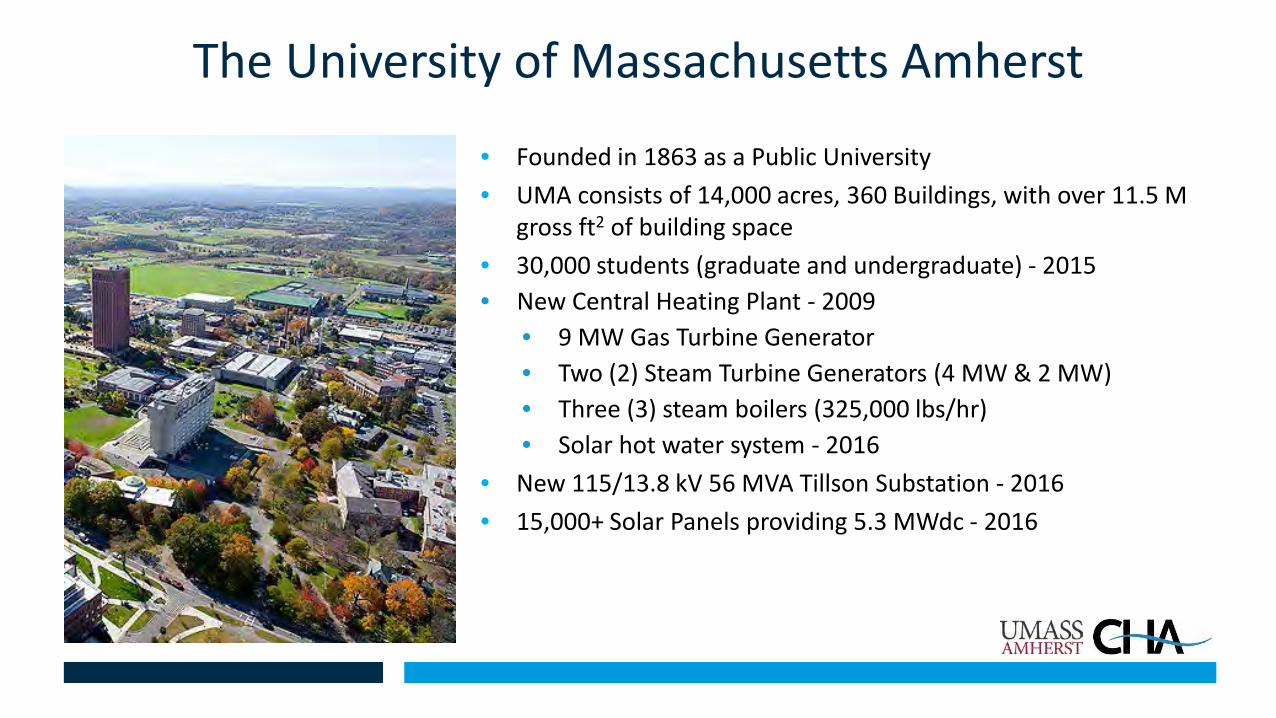
The University of Massachusetts Amherst
• Founded in 1863 as a Public University• UMA consists of 14,000 acres, 360 Buildings, with over 11.5 M
gross ft2 of building space• 30,000 students (graduate and undergraduate) - 2015• New Central Heating Plant - 2009
• 9 MW Gas Turbine Generator• Two (2) Steam Turbine Generators (4 MW & 2 MW)• Three (3) steam boilers (325,000 lbs/hr)• Solar hot water system - 2016
• New 115/13.8 kV 56 MVA Tillson Substation - 2016• 15,000+ Solar Panels providing 5.3 MWdc - 2016
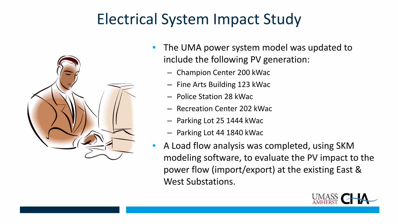
Electrical System Impact Study
• The UMA power system model was updated to include the following PV generation:– Champion Center 200 kWac– Fine Arts Building 123 kWac– Police Station 28 kWac– Recreation Center 202 kWac– Parking Lot 25 1444 kWac– Parking Lot 44 1840 kWac
• A Load flow analysis was completed, using SKM modeling software, to evaluate the PV impact to the power flow (import/export) at the existing East & West Substations.


Electrical System Impact Study• Multiple scenarios were studied which included:
– Base Case
– All PV & existing UMA generation operating
– All PV & existing UMA generation curtailed (GTG @ 77%)
Bus Load Flow ResultEast Side Bus 1 Import 1809.7 kWEast Side Bus 2 Import 1891.7 kWWest Side Bus 1 Import 228.7 kWWest Side Bus 2 Import 202.7 kW
Bus Load Flow ResultEast Side Bus 1 Export 168.4 kWEast Side Bus 2 Import 1891.7 kWWest Side Bus 1 Export 769.7 kWWest Side Bus 2 Export 765.5 kW
Bus Load Flow ResultEast Side Bus 1 Import 221.1 kWEast Side Bus 2 Import 1891.7 kWWest Side Bus 1 Import 209.8 kWWest Side Bus 2 Import 215.2 kW
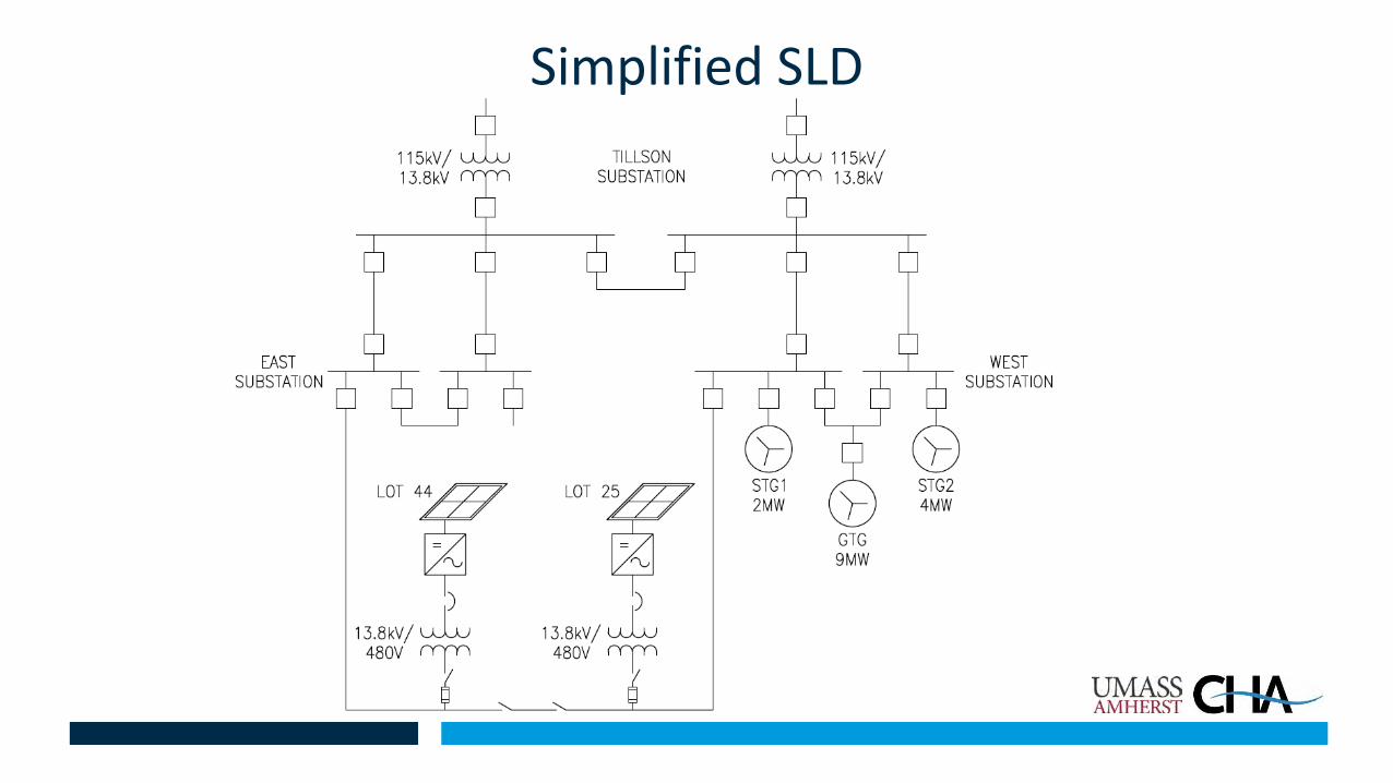
Simplified SLD
Study Results/Recommendations
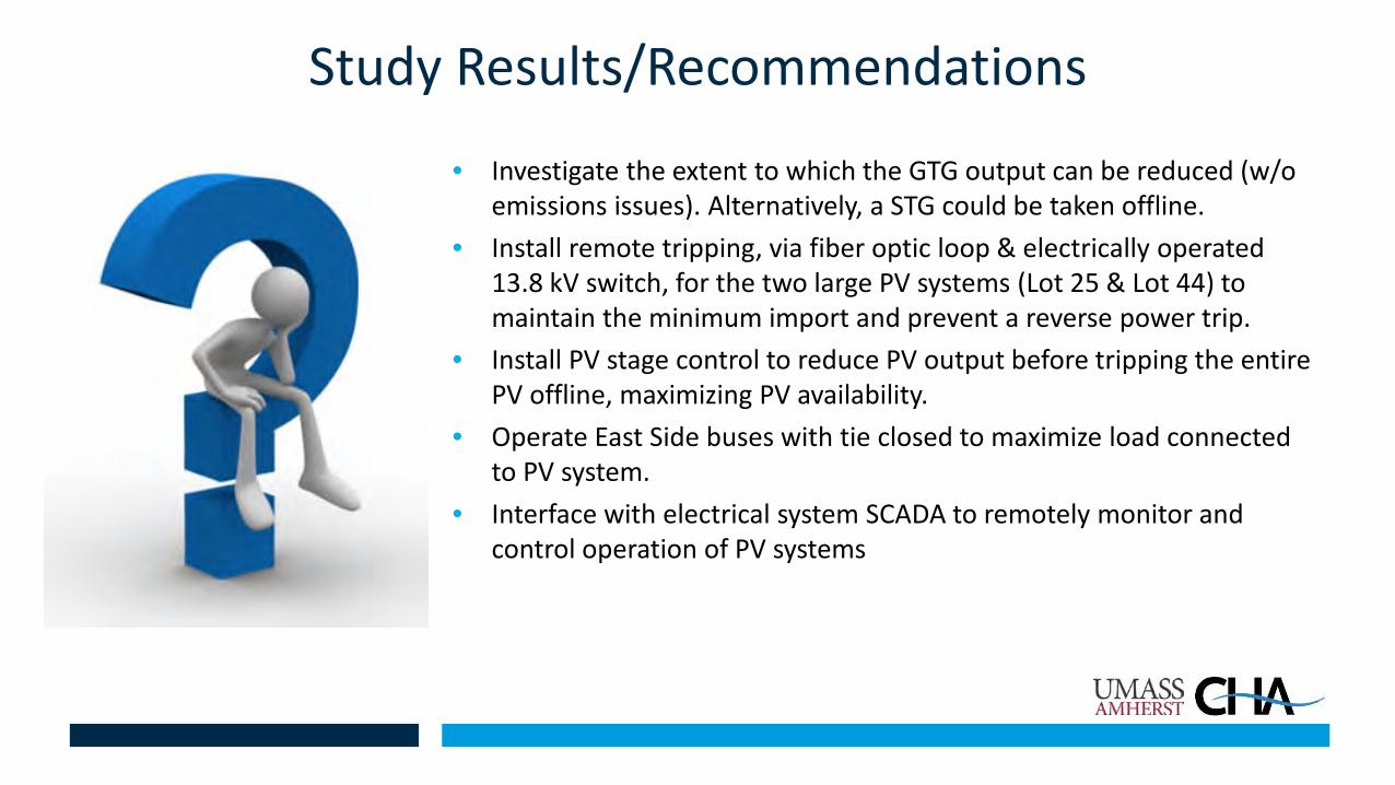
• Investigate the extent to which the GTG output can be reduced (w/o emissions issues). Alternatively, a STG could be taken offline.
• Install remote tripping, via fiber optic loop & electrically operated 13.8 kV switch, for the two large PV systems (Lot 25 & Lot 44) to maintain the minimum import and prevent a reverse power trip.
• Install PV stage control to reduce PV output before tripping the entire PV offline, maximizing PV availability.
• Operate East Side buses with tie closed to maximize load connected to PV system.
• Interface with electrical system SCADA to remotely monitor and control operation of PV systems

Major PV Components Interconnection
• East Substation upgrades:– New Basler BE1-11F relays with reverse power
protection were added to the main circuit breakers.– The reverse power elements (32) would control the
opening of the PV lot stages via the PV controllers (SEL 2440’s).
– 300:5A C200 current transformer were added to the line side of each circuit breaker.
– New GE F60 relays were added for enhanced protection and control.
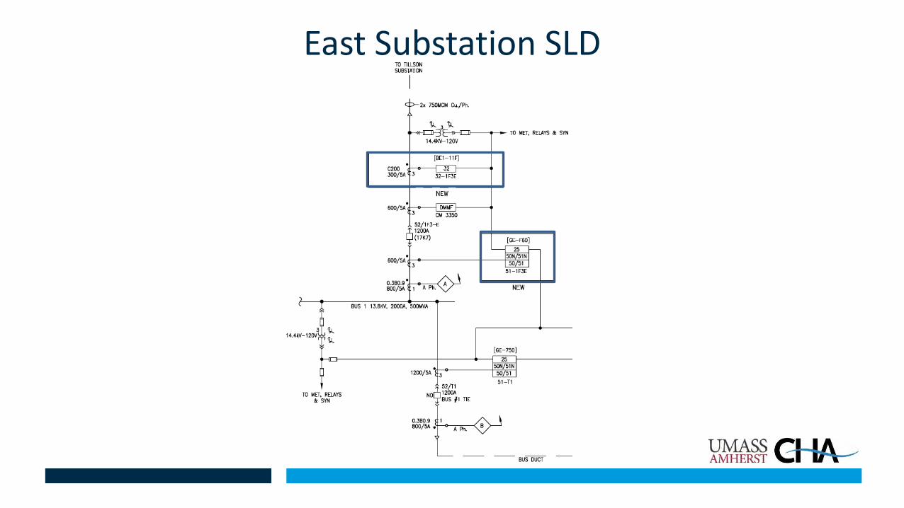
East Substation SLD
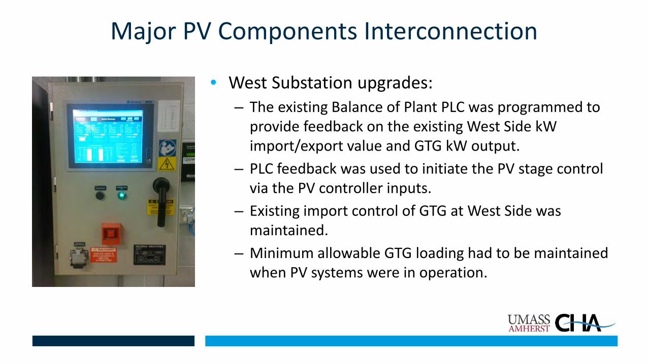
Major PV Components Interconnection
• West Substation upgrades:– The existing Balance of Plant PLC was programmed to
provide feedback on the existing West Side kW import/export value and GTG kW output.
– PLC feedback was used to initiate the PV stage control via the PV controller inputs.
– Existing import control of GTG at West Side was maintained.
– Minimum allowable GTG loading had to be maintained when PV systems were in operation.

Communications between East & West Subs and PV
• Four (4) SEL 2440’s were added for PV control. One (1) 2440 was added at each PV lot, and another 2440 was added at the upstream substation (East & West). • To prevent an export of power by opening up to
five AC contactors (stages) at each PV lot.• Control both PV lot’s main disconnect switch
(S&C PMH).• Provide a UMA Operator interface for control via
SCADA & HMI.
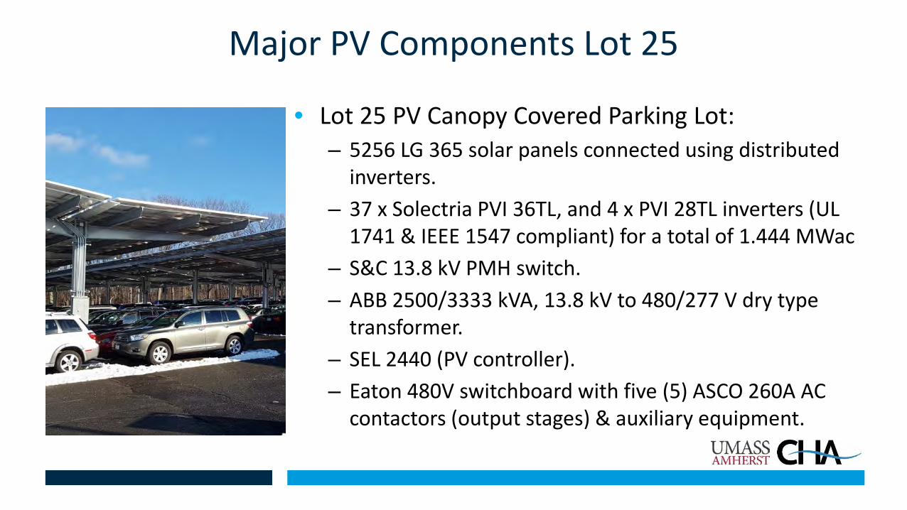
Major PV Components Lot 25
• Lot 25 PV Canopy Covered Parking Lot:– 5256 LG 365 solar panels connected using distributed
inverters.– 37 x Solectria PVI 36TL, and 4 x PVI 28TL inverters (UL
1741 & IEEE 1547 compliant) for a total of 1.444 MWac– S&C 13.8 kV PMH switch.– ABB 2500/3333 kVA, 13.8 kV to 480/277 V dry type
transformer.– SEL 2440 (PV controller).– Eaton 480V switchboard with five (5) ASCO 260A AC
contactors (output stages) & auxiliary equipment.


Major PV Components Lot 44• Lot 44 PV Canopy Covered Parking Lot:
– 7038 LG 365 solar panels connected using distributed inverters.
– 48 x Solectria PVI 36TL, 3 x PVI 28TL, and 3 x PVI 23TL inverters (UL 1741 & IEEE 1547 compliant) for a total of 1.881 MWac.
– S&C 13.8 kV PMH switch– ABB 2500/3333 kVA, 13.8 kV to 480/277 V dry type
transformer.– SEL 2440 (PV controller).– Eaton 480V switchboard with five (5) ASCO 260A AC
contactors (output stages) & auxiliary equipment.
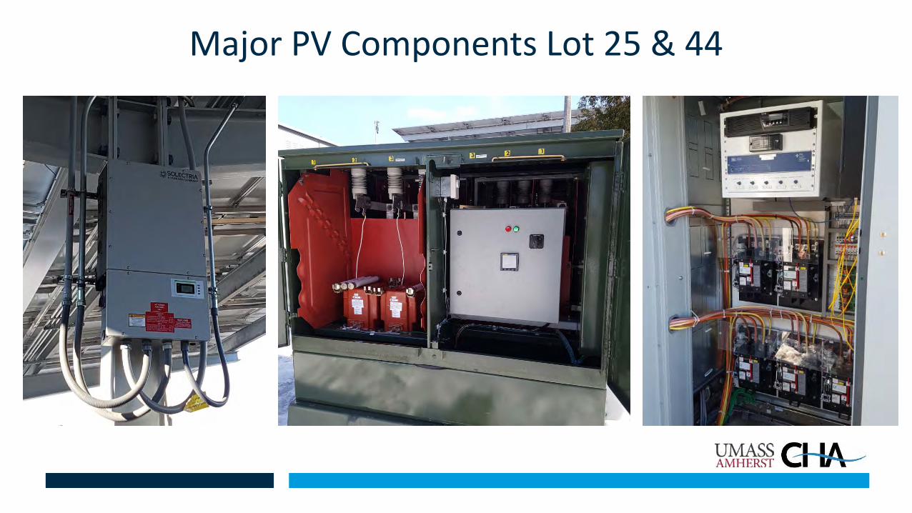
Major PV Components Lot 25 & 44

Integration into Existing SCADA System
• The existing GE SCADA system was upgraded to include:– Provide control, status, and alarm indication for:
• Each PV lot disconnect switch (S&C PMH)• Each PV lot stage control
– New HMI mimic screens.


Operating Description & Control Logic Lot 25• If the GTG output drops below 7.2 MW -initiates automatic staggered opening of the
Lot 25 PV output stages (108 kW/stage). The first Lot 25 PV stage will immediately open, and every 10 seconds later another stage will automatically open until all stages are opened, or the GTG output increases above 7.2 MW.
• If the GTG output drops below 6 MW, the Lot PMH-25 switch will automatically open to prevent the GTG output from dropping below the minimum output.
• If the GTG output increases above 8 MW, initiates automatic staggered closing of the Lot 25 PV stages. The first Lot 25 PV stage will immediately close and then every 7 min later another stage will automatically close until all stages are closed, or until the GTG output drops below 8 MW.

Operating Description & Control Logic Lot 44• If the import of power through the East Substation main circuit breaker(s) is less than 200 kW
- initiates automatic staggered opening of the Lot 44 stages. The first Lot 44 stage will immediately open, and every 10 seconds later another stage will automatically open until the import of power through the East Substation main circuit breaker(s) is greater than 200 kW.
• If the import of power through the East Substation main circuit breaker(s) is less than 200 kW, the PMH-44 switch will automatically open to prevent the export of power 10 seconds after all five (5) Lot 44 stages are opened, or once the import of power is less than 200 kW for longer than 60 seconds.
• If the import of power through the East Substation main circuit breaker(s) is greater than 400 kW - initiates automatic staggered closing of the Lot 44 stages. The first Lot 44 stage will immediately close, and every 7 minutes later another stage will automatically close until the import of power through the East Substation main circuit breaker(s) is less than 400 kW.

Challenges
• Developer / Contractor Relations / Communications• PV equipment procurement • Existing installation modifications & testing• Fiber optic communication installation• Coordinating SCADA integration work• In-service deadlines


The University of MassachusettsPV Interconnection Project
Thank you