Embed Size (px)
Citation preview
The SpecC MethodologyTechnical Report ICS-99-56December 29, 1999Daniel D. GajskiJianwen ZhuRainer DoemerAndreas GerstlauerShuqing ZhaoDepartment of Information and Computer ScienceUniversity of California, IrvineIrvine, CA 92697-3425, USA(949) 824-8059fgajski, jzhu, doemer, gerstl, [email protected]

The SpecC MethodologyTechnical Report ICS-99-56December 29, 1999Daniel D. GajskiJianwen ZhuRainer DoemerAndreas GerstlauerShuqing ZhaoDepartment of Information and Computer ScienceUniversity of California, IrvineIrvine, CA 92697-3425, USA(949) 824-8059fgajski, jzhu, doemer, gerstl, [email protected] report describes the SpecC methodology for system-level embedded system design. The methodologyconsists of a set of well-de�ned tasks and design models which allow the easy insertion and reuse of intellectualproperty. Starting from the abstract executable speci�cation written in SpecC di�erent design alternativesconcerning the system architecture (components and communication) can be explored and the speci�cationis gradually re�ned and mapped to a �nal HW/SW implementation such that the constraints are satis�edoptimally. The �nal hand-o� for manufacturing includes software code compiled for the processors and theRTL descriptions for hardware synthesis.

Contents1 Introduction 12 Overview 13 Speci�cation 33.1 Speci�cation Model . . . . . . . . . . . . . . . . . . . . . . . . . . . . . . . . . . . . . . . . . . . . . 33.2 Architecture exploration . . . . . . . . . . . . . . . . . . . . . . . . . . . . . . . . . . . . . . . . . . 73.2.1 Allocation . . . . . . . . . . . . . . . . . . . . . . . . . . . . . . . . . . . . . . . . . . . . . . 73.2.2 Behavior partitioning . . . . . . . . . . . . . . . . . . . . . . . . . . . . . . . . . . . . . . . 73.2.3 Scheduling . . . . . . . . . . . . . . . . . . . . . . . . . . . . . . . . . . . . . . . . . . . . . 83.2.4 Variable partitioning . . . . . . . . . . . . . . . . . . . . . . . . . . . . . . . . . . . . . . . . 103.2.5 Channel Partitioning . . . . . . . . . . . . . . . . . . . . . . . . . . . . . . . . . . . . . . . . 113.2.6 Architecture Model . . . . . . . . . . . . . . . . . . . . . . . . . . . . . . . . . . . . . . . . . 143.3 Communication Synthesis . . . . . . . . . . . . . . . . . . . . . . . . . . . . . . . . . . . . . . . . . 143.3.1 Protocol Insertion . . . . . . . . . . . . . . . . . . . . . . . . . . . . . . . . . . . . . . . . . 183.3.2 Transducer Synthesis . . . . . . . . . . . . . . . . . . . . . . . . . . . . . . . . . . . . . . . . 183.3.3 Protocol inlining . . . . . . . . . . . . . . . . . . . . . . . . . . . . . . . . . . . . . . . . . . 203.3.4 Communication Model . . . . . . . . . . . . . . . . . . . . . . . . . . . . . . . . . . . . . . . 213.4 Backend . . . . . . . . . . . . . . . . . . . . . . . . . . . . . . . . . . . . . . . . . . . . . . . . . . . 243.4.1 Software Compilation . . . . . . . . . . . . . . . . . . . . . . . . . . . . . . . . . . . . . . . 243.4.2 Hardware Synthesis . . . . . . . . . . . . . . . . . . . . . . . . . . . . . . . . . . . . . . . . 243.4.3 Implementation Model . . . . . . . . . . . . . . . . . . . . . . . . . . . . . . . . . . . . . . . 244 Summary 25References 25
i

List of Figures1 The SpecC methodology. . . . . . . . . . . . . . . . . . . . . . . . . . . . . . . . . . . . . . . . . . . 22 Speci�cation model of design example. . . . . . . . . . . . . . . . . . . . . . . . . . . . . . . . . . . 43 SpecC code for speci�cation model of design example. . . . . . . . . . . . . . . . . . . . . . . . . . 44 Synchronization of shared variable accesses in the speci�cation model. . . . . . . . . . . . . . . . . 55 SpecC code for the synchronization channel. . . . . . . . . . . . . . . . . . . . . . . . . . . . . . . . 66 Intermediate model after behavior partitioning. . . . . . . . . . . . . . . . . . . . . . . . . . . . . . 87 Intermediate model after scheduling. . . . . . . . . . . . . . . . . . . . . . . . . . . . . . . . . . . . 88 Model after behavior partitioning. . . . . . . . . . . . . . . . . . . . . . . . . . . . . . . . . . . . . 109 Example model after variable partitioning to a dedicated memory. . . . . . . . . . . . . . . . . . . 1110 Example model after variable partitioning to local memories. . . . . . . . . . . . . . . . . . . . . . 1211 Model of design example after channel partitioning. . . . . . . . . . . . . . . . . . . . . . . . . . . . 1312 SpecC code for architecture model of design example. . . . . . . . . . . . . . . . . . . . . . . . . . 1513 Synchronization inside leaf behaviors of the architecture model. . . . . . . . . . . . . . . . . . . . . 1614 SpecC code for message-passing channel. . . . . . . . . . . . . . . . . . . . . . . . . . . . . . . . . . 1715 Model of design example after protocol insertion. . . . . . . . . . . . . . . . . . . . . . . . . . . . . 1816 Model with IPs after protocol and transducer insertion. . . . . . . . . . . . . . . . . . . . . . . . . 1917 Model after protocol inlining. . . . . . . . . . . . . . . . . . . . . . . . . . . . . . . . . . . . . . . . 2018 Model with IPs after protocol inlining. . . . . . . . . . . . . . . . . . . . . . . . . . . . . . . . . . . 2119 SpecC code for communication model of design example. . . . . . . . . . . . . . . . . . . . . . . . . 22
ii

The SpecC MethodologyD. Gajski, J. Zhu, R. Domer, A. Gerstlauer, S. ZhaoInformation and Computer ScienceUniversity of California, IrvineIrvine, CA 92697-3425, USAAbstractThis report describes the SpecC methodology for system-level embedded system design. The methodology consistsof a set of well-de�ned tasks and design models which allow the easy insertion and reuse of intellectual property.Starting from the abstract executable speci�cation written in SpecC di�erent design alternatives concerning thesystem architecture (components and communication) can be explored and the speci�cation is gradually re�nedand mapped to a �nal HW/SW implementation such that the constraints are satis�ed optimally. The �nal hand-o� for manufacturing includes software code compiled for the processors and the RTL descriptions for hardwaresynthesis.1 IntroductionWe de�ne a methodology as a set of models and transformations that can re�ne an initial, functional systemspeci�cation into a detailed implementation description ready for manufacturing. The SpecC design methodologywe discussed in this report is based on four well-de�ned models, namely, a speci�cation model, an architecturemodel, a communication model, and �nally, an implementation model.In the following sections, we will give a detailed description of each model and of the re�nement tasks leadingfrom a functional speci�cation model all the way to a cycle-accurate implementation model in SpecC.2 OverviewThe SpecC system-level design methodology starts with the capture of the intended functionality in the form of anexecutable speci�cation as shown in Figure 1. This initial speci�cation model describes the functionalityas well as the performance, power, cost and other constraints of the intended design. It does not make anypremature allusions to implementation details. During speci�cation capture the designer may reuse existing codesegments, functions or procedures by instantiating them out of an algorithm library.The synthesis ow of the SpecC methodology consists of two major tasks: architecture exploration and com-munication synthesis tasks. Through a series of well-de�ned steps the initial speci�cation is gradually mappedonto a selected target architecture.Architecture exploration, which re�nes the speci�cation into an architecture model, includes the designsteps of allocation, partitioning of behaviors, channels, and variables, and scheduling. Allocation determines thenumber and types of the system components, such as general-purpose or custom processors, memories, and busses,which will be used to implement the system behavior. Allocation includes the reuse of intellectual property (IP),when IP components are selected from the component library.Next, behavior partitioning distributes the behaviors (or processes) that comprise the system functionalityamongst the allocated processing elements, while variable partitioning assigns variables to memories, andchannel partitioning assigns communication channels to busses. Scheduling determines the order of execution1

Manufacturing
Communication synthesis
Synthesis flow
Architecture exploration
Validation flow
Communication
modelSpecification
Architecturemodel
model
Simulationmodel
Estimation
ValidationAnalysis
Compilation
LibraryComp.
Simulationmodel
Estimation
ValidationAnalysis
Compilation
Simulationmodel
Estimation
ValidationAnalysis
Compilation
Simulationmodel
Estimation
ValidationAnalysis
Compilation
Interface synthesis
Implementation
Hardware
synthesis
Software
compilation Library
Back end
Capture
modelImplementation
Library
LibraryAlg.
RTL
Allocation
Partitioning
Scheduling
Protocol insertion
Protocol inlining
Proto.
Figure 1: The SpecC methodology.of the behaviors assigned to either the standard or custom processors after partitioning. In other words, schedulingis used for software and hardware components.Architecture exploration is an iterative process culminating with an architecture model which representsa re�nement of the speci�cation model. Estimators evaluate each architecture candidate's satisfaction of thedesign constraints; until all constraints are satis�ed, component and connectivity reallocation is performed anda new architecture with di�erent components, connectivity, partitions, schedules or protocols is generated andevaluated.Communication synthesis re�nes the abstract communications between behaviors in the architecture modelinto an implementation. The task of communication synthesis includes the insertion of communication protocols,synthesis of interfaces and transducers, and inlining of protocols into synthesizable components. In the resultingcommunication model, communication is described in terms of actual wires and timing relationships aredescribed by bus protocols.The result of the synthesis ow is handed o� to the back-end tools, as shown in the lower part of Figure 1. Thesoftware part of the hand-o� model consists of C code for compilation and the hardware part consists of behavioralC (VHDL) code for high-level synthesis. The back-end tools include compilers and a high-level synthesis tool.The compilers are used to compile the software C code for the chosen processor. The high-level synthesis toolsynthesizes the functionality assigned to custom hardware and the functionality of transducers which are necessaryfor connecting di�erent processors, memories, and IPs.After software compilation and hardware synthesis, the �nal implementation model is generated, represent-ing a clock-cycle accurate description of the whole system. This description, in turn, then serves as the basis formanufacturing of the system.In each of the tasks the designer can make design decisions manually by using an interactive graphical userinterface, for example, while transformations from one model into another can be accomplished automaticallyby following the re�nement rules or model guidelines which will be described later in this chapter. After eachre�nement step in the synthesis ow, a corresponding SpecC model of the system is generated, which means that2

design decisions made in each design task are re ected in the generated models. Thus, in the validation owthat is orthogonal to the synthesis ow in the SpecC methodology, one can perform simulation, analysis andestimation of the SpecC models generated after each task.After each design step, the design model is statically analyzed to estimate certain quality metrics such asperformance, cost, and power consumption. Analysis and estimation results are reported to the user and back-annotated into the model for simulation and further synthesis.The design can be statically analyzed or simulated after each step for validation of design correctness in termsof functionality, performance, and other constraints. A simulation model is compiled after each step which canbe run on the host computer to validate correctness for simulation. For example, at the speci�cation stage,the simulation model is used to verify the functional correctness of the intended design. After architectureexploration, the simulation model will verify the performance of behaviors on di�erent processing elements (PEs).After communication synthesis, the bus-functional model is used to verify the communication and synchronizationbetween processing elements.At any stage of the re�nement process, a standard software debugger can be used to locate and �x the errorsif veri�cation fails. Such debuggers enable one to set break points anywhere in the source code and to performdetailed state inspection at any time.3 Speci�cationThe synthesis ow begins with the capture of a speci�cation of the system being designed. The speci�cation iscaptured either textually by use of a standard text editor or visually by use of a graphical design entry tool whichallows to capture the behavioral and structural hierarchy via a graphical user interface.An executable speci�cation in a formal description language describes the functionality of the system alongwith performance, cost and other constraints, but without premature allusions to implementation details. Thespeci�cation should be as close to the computational model of the system as possible.The source code can be executed with the help of a simulator and a set of test vectors, while errors can bedetected with debugger tools. This step veri�es the algorithms and the functionality of the system. Obviously,it is easier and more e�cient to verify the correctness of the algorithms at a higher abstraction level than at alower level which includes the implementation details as well.In our system, we use the SpecC language, described in detail in [ZDG97], to capture the high-level speci�ca-tion of the system under design. SpecC is a superset of C [X3Sec90] and provides special language constructs formodeling concurrency, state transitions, structural and behavioral hierarchy, exception handling, timing, com-munication and synchronization. This is very di�erent from popular hardware description languages, like VHDL[IEEE98] and Verilog [TM91], which do not include explicit constructs for state transitions, communication, andstandard programming languages like C/C++ [Str97] and Java [AG96], which cannot directly model timing,concurrency, structural hierarchy, and state transitions. Thus, SpecC is appropriate for specifying the SFSMD orPSM computational models de�ned in [GVNG94].In addition, SpecC is synthesizable and aids the designer in developing \good" designs by providing the featureslisted above as language constructs, rather than just supporting them in some contrived way. Another importantfeature of SpecC is its emphasis on separation of communication and computation at higher levels of abstraction.This dichotomy is essential for supporting plug-and-play of IPs. SpecC achieves this by using abstract functioncalls in the port interfaces of behaviors. The function calls are themselves implemented by communicationchannels. An executable speci�cation in SpecC includes only the computation portion and uses a model similarto remote procedure calls (RPC) for communication. The actual communication methods are resolved andinlined during the re�nement process for the �nal implementation model.3.1 Speci�cation ModelIn the SpecC methodology, the speci�cation model is the model with the highest level of abstraction. It isan accurate model of the intended system in terms of pure functionality but does not re ect its structure ortiming. Typically, the speci�cation model executes in zero simulation time. Neither the computation nor anycommunication is modeled with timing. 3

B0
B1
B2
B3
B4
B5
B6
B7
data, sync
syncdata
v3
v3
v1 v2
v1
v2Figure 2: Speci�cation model of design example.behavior B5( in int v1 , out int data ,ISyncOut sync , out int v2 ) fint v3 ;B6 b6 ( v1 , data , sync , v3 ) ;5 B7 b7 ( v3 , v2 ) ;void main(void ) fb6 . main ( ) ;b7 . main ( ) ;10 gg ;behavior B2( in int v1 , out int v2 ) fint data ;15 CSync sync ;B4 b4 ( v1 , data , sync ) ;B5 b5 ( v1 , data , sync , v2 ) ;void main(void ) f20 par fb4 . main ( ) ;b5 . main ( ) ;gg25 g ;behavior B0() fint v1 , v2 ;B1 b1 ( v1 ) ;30 B2 b2 ( v1 , v2 ) ;B3 b3 ( v2 ) ;void main(void ) fb1 . main ( ) ;35 b2 . main ( ) ;b3 . main ( ) ;gg ; Figure 3: SpecC code for speci�cation model of design example.4

We illustrate our methodology with a simple example design. The speci�cation model of the example is shownin Figure 2. The corresponding SpecC code is shown in Figure 3. The top level behavior B0 consists of threesequential behaviors: B1, B2 and B3. The system starts execution with behavior B1. When B1 completes, thesystem transitions to B2. Finally, the system transitions to B3 upon behavioral completion of B2. Behavior B2again is a compound behavior, composed of two concurrent behaviors: B4 and B5. Behavior B4 is a leaf behaviorlike B1 and B3. On the other hand, B5 is hierarchical and consists of two sequential behaviors: B6 and B7.behavior B4( in int v1 , out int data ,ISyncIn sync ) fvoid main(void ) f. . .5 sync . recv ( ) ; // wait for synchron i za t i on. . .x = data ; // use " data ". . .g10 g ;behavior B6( in int v1 , in int data ,ISyncOut sync , out int v3 ) fvoid main(void ) f15 . . .data = f ( y ) ; // ass ign " data ". . .sync . send ( ) ; // send synchron i za t i on. . .20 gg ; Figure 4: Synchronization of shared variable accesses in the speci�cation model.The leaf behaviors B1 and B3 communicate with behavior B2 via variables v1 and v2, respectively. InsideB2, the concurrent behaviors B4 and B6 communicate through the shared variable data. B6 synchronizes itsexecution and hence the shared variable access with B4 over the synchronization channel sync, as shown inFigure 4 and symbolized by the dashed arrow in Figure 2. The channel with simple synchronization semantics,shown in Figure 5, is instantiated out of the SpecC communication library. Finally, as shown in the code (Figure 3),data is communicated from behavior B6 to behavior B7 through the variable v3, and B7 in turn produces theoutput value of v2. Note that although all variables are of plain integer type in the example code, in general datacommunicated can be of arbitrarily complex type.In general, communication can be modeled in two ways, either as shared variables or by use of channels fromthe SpecC communication library. Communication channels which are useful for a speci�cation model are thosewith basic synchronization, such as one-way or two-way handshaking, and channels for data communication suchas blocking and non-blocking FIFOs. Communication in the speci�cation over shared global variables or viachannels implies nothing about the way it will be implemented later. For the implementation, the communicationscheme could be transformed into a message passing or a shared memory mechanism.The speci�cation model can be composed using any of the constructs supported through the SpecC language.The initial speci�cation should model the system at a very abstract level without prematurely introducing un-necessary implementation details. When developing the initial speci�cation, a designer has to follow certainmodeling guidelines in order to achieve optimal results. Basically, the speci�cation should capture the requiredsystem functionality in a natural way and in a clear and concise manner, expressing essential features of thespeci�cation explicitly.Table 1 gives the guidelines for developing the initial system speci�cation. The language provides all thenecessary support to e�ciently describe the desired system features following these guidelines. Hence, each of themodeling concepts like parallelism or hierarchy is re ected in the SpecC description in an explicit and clear way.5

interface ISyncIn fvoid recv ( ) ;g ;interface ISyncOut f5 void send ( ) ;g ;channel CSync ()implements ISyncIn , ISyncOut10 f bool val id = fa lse ;event e ;void send ( ) f15 val id = true ;notify ( e ) ;gvoid recv ( ) fi f ( ! va l id ) wait ( e ) ;20 val id = fa lse ;gg ; Figure 5: SpecC code for the synchronization channel.Table 1: Speci�cation model guidelines.Separate communication and computationAlgorithmic functionality has to be detached from communication functionality. In addition, inputs andoutputs of a computation have to be explicitly speci�ed to show data dependencies.Expose parallelismAllow independent behaviors to run concurrently instead of arti�cially serializing behaviors in expectancyof a serial implementation. In essence, all parallelism should be made available to the exploration toolsin order to increase room for optimizations.Use hierarchy to group related functionalityIntroduce one hierarchical level for each functional group and eliminate localized e�ects at higher levels.For example, local communication and local data dependencies are grouped and hidden by the hierarchicalstructure.Choose proper granularityThe size of leaf behaviors has to be chosen such that optimization possibilities and design complexityare balanced when searching the design space. Basically, the leaf behaviors, which build the smallestindivisible units for exploration, should re ect the division into basic algorithmic blocks.Identify system statesUse state transitions to explicitly model the steps of the computation in terms of basic algorithms orabstracted, hierarchical blocks.
6
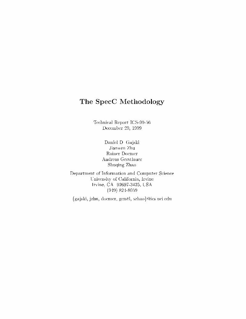
3.2 Architecture explorationThe �rst major re�nement step in the synthesis ow is the task of architecture exploration which includes allo-cation, partitioning and scheduling.Allocation is usually done manually by the designer and basically involves selection of components froma library. In general, three types of components have to be selected from the component library: processingelements, called PEs (where a PE can be a standard processor or custom hardware), memories, and busses. Ofcourse, the component library can include IP components and parts which have already been designed and whichcan be reused.The set of selected and interconnected components is called the system target architecture. The task ofpartitioning, then, is to map the system speci�cation onto this architecture. In particular, behaviors are mappedto PEs, variables are mapped to memories, and channels are mapped to busses. Scheduling of the behaviorsmapped to each PE is then used to serialize execution. In the SpecC methodology, the resulting architecturemodel, like the initial speci�cation, is modeled in SpecC.Note that in general, exploration is an iterative process. The di�erent tasks can be executed repeatedly andin each iteration the task can be done generally in any order or even simultaneously.In order to perform architecture exploration, it is crucial to obtain accurate information about the design in ashort amount of time. Therefore, the task of estimation is central to the whole exploration process. Estimationtools determine design metrics such as performance (execution time) and memory requirements (code and datasize) for each part of the speci�cation with respect to the allocated components. Estimation is performed as acombination of static analysis of the speci�cation and dynamic pro�ling of the design description during functionalsimulation. Obviously estimation has to support software, hardware and bus components.The estimation results are back-annotated into the corresponding behaviors and channels of the architecturemodel. There, they are used during simulation and synthesis in order to obtain feedback on whether the designconstraints are met and to drive the decision making process during exploration in order to optimize the design.3.2.1 AllocationThe task of architecture allocation is the selection of the type and number of components from a given libraryof system components, such as processors, memories, and busses. Allocation also determines the interconnectionamong the selected components. All of this has to be done in such a way that the functionality of the system canbe implemented, all design constraints are satis�ed, and the objective cost function is minimized.During architecture allocation in the SpecC methodology, three types of components are selected from thecomponent library. First, processing elements (PEs), including standard processors and custom processors, areneeded as active elements performing the systems functions. Second, memories are needed to store the processingdata. Finally, busses are allocated for the communication among the PEs and memories. Note that for eachcomponent type either a synthesizable, custom component or a predesigned IP can be selected. For the systembusses, the designer selects the appropriate communication protocol from a library of bus/protocol schemes. Inaddition, the designer has the option of including custom protocols or customizing available protocols to suit thecurrent application.The network of selected components is called the target architecture of the system. The architecture consistsof a set of system ports, a set of system busses, a set of system components, and a connectivity matrix whichdetermines the interconnections among the ports, busses, and components.3.2.2 Behavior partitioningBehaviors are partitioned among the allocated processing elements; this decides which behavior is going to beexecuted on which PE. For example, behaviors to be implemented in software are separated from behaviors tobe implemented in hardware. Based on a partitioning decision the design model is re�ned to re ect the selectedpartition.For our design example we assume that two processing elements, PE0 and PE1 (a standard processor andsynthesizable custom hardware), have been allocated. The speci�cation model from Figure 2 after partitioning isshown in Figure 6. Here, the behaviors B0, B2, B3, B5, B6 and B7 are assigned to PE0 (executing in software),7

PE0 PE1
B0
B2B5
B6
B7
B3
B4_ctrl
B1
B4
B1_ctrlB1_start
B1_done
B4_start
B4_done
syncdatav1
v3
v2
B1_syn B4_syn
Figure 6: Intermediate model after behavior partitioning.B1
B3
B4
B6
B7
PE0 PE1B1_start
B1_done
B4_start
B4_done
data, sync
syncdatav1 B1_syn B4_synB0
v2 v3
B1_ctrl
B4_ctrl (a) non-optimized B3
B6
B7
PE0
B1
B4
PE1
data, sync
B0
B1_done
B4_done
syncdatav1 B1_syn B4_syn
v2 v3
(b) optimizedFigure 7: Intermediate model after scheduling.and the behaviors B1 and B4 are assigned to PE1 (implemented in hardware). In order to maintain the executionsemantics of the speci�cation, two additional behaviors, B1 ctrl and B4 ctrl, are inserted which synchronize theexecution with B1 and B4, respectively. The variables v1, data and the channel sync are used for communicationbetween behaviors in di�erent components and hence became global system variables. Also, for the additionalsynchronization of behaviors between components, two global synchronization channels B1 syn and B4 syn areadded which handle the respective start and done signaling, as shown in Figure 6.In summary, the steps involved in creating the re�ned design model after behavior partitioning are shown inTable 2.3.2.3 SchedulingThe assignment of possibly concurrent behaviors to the inherently sequential PEs requires scheduling. The taskof scheduling determines the order of execution for the behaviors that execute on a processor. The schedulerensures that the schedule does not violate any dependencies imposed by the speci�cation and tries to optimizeobjectives speci�ed by the designer. After a schedule is determined, the design model is re�ned so that it re ectsthe sequentialization of the behaviors assigned to the same PE.In general, scheduling can be either time-constrained or resource-constrained. For time-constrained schedul-ing, the designer supplies a set of timing constraints. Each timing constraint speci�es the minimum and maximumtime between two behaviors. The scheduler therefore has to compute a schedule in which no behavior violatesany of the timing constraints, and which can minimize the number of resources used. On the other hand, forresource-constrained scheduling, the designer speci�es constraints on the available resources. The scheduler8

Table 2: Re�nement rules for behavior partitioning.Introduce additional level of hierarchyAt the top-level of the behavior hierarchy, insert behaviors which represent the components of the systemarchitecture.Bind behaviors to componentsAnnotate the component behaviors with the name of the component type out of the component library.Since the inserted behaviors simply group behaviors for each PE, this establishes the correlation of PEbehaviors with allocated components in the system architecture.Group behaviorsGroup the behaviors of the speci�cation under the component behavior to which they have been mapped,preserving the structural and behavioral hierarchy of the speci�cation in the parts mapped to eachcomponent.Estimate behavior metricsAnnotate the behaviors with the estimated values of chosen metrics for the components executing thebehaviors. For example, in leaf behaviors appropriate wait() statements are added to establish correctexecution times during simulation.Add synchronizationFor original behavior transitions that now cross component boundaries, introduce additional controlbehaviors in each component and corresponding global synchronization channels in order to preserveexecution semantics.Move communicationMove variables and channels in the original speci�cation that are used for communication between behav-iors mapped to di�erent components to the top level and declare them as global system variables/channels.Add corresponding ports and connections in the structural hierarchy from the top down to the behaviorsaccessing the variables and channels.then creates a schedule while optimizing execution time, such that all the subtasks are completed in the shortesttime possible, given the restrictions on the resource usage.Scheduling may be done statically or dynamically. In static scheduling, each behavior is executed accordingto a �xed schedule. The scheduler computes the best schedule at design time and the schedule does not changeat run time. On the other hand, in dynamic scheduling, the execution sequence of the subtasks is determinedat run-time. An embedded real-time operating system (RTOS) maintains a pool of behaviors ready to beexecuted. A behavior becomes ready for execution when all its predecessor behaviors have been completed andall inputs are available. With a non-preemptive scheduler, a behavior is selected from the ready list as soon asthe current behavior �nishes, whereas for a scheduler with preemption, a running behavior may be interruptedin its computation when another behavior with higher priority becomes ready to execute.After a schedule is created, the scheduler moves the leaf behaviors into the scheduled order and also addsnecessary synchronization signals and constructs to the behaviors. This re�ned model then re ects the tasksperformed for behavior partitioning including scheduling. Since, in the SpecC system, all design models arecaptured with the same language, the scheduled model is also speci�ed in SpecC.We illustrate the scheduling process with the intermediate model after behavior partitioning, as shown beforein Figure 6. Figure 7 shows how scheduling is performed for this example. As shown in Figure 7(a), the behavioralhierarchy inside PE0 is attened and its leaf behaviors are sequentialized. For PE1, the behavior changes from(potentially) concurrent to sequential execution.Due to scheduling, some explicit synchronization can become redundant. Figure 7(b) shows the optimizedversion of the example. Here, the behaviors B1 ctrl and B4 ctrl, which were introduced in the partitioning stage,are removed, together with any obsolete synchronization signals.The rules for creating the re�ned, scheduled model are summarized in Table 3.9
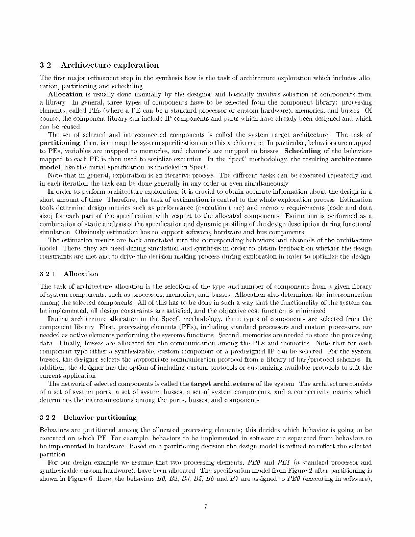
Table 3: Re�nement rules for scheduling.Serialize behavior hierarchyInside the PE behaviors, remove all concurrent (parallel, pipe) behaviors and transform the behaviorhierarchy according to the selected schedule into a purely sequential execution. Possibly atten parts ofthe hierarchy or move behaviors across the hierarchy.Optimize controlOptimize the scheduled hierarchy by removing unnecessary control and synchronization behaviors andchannels.
PE1PE0
sync
data
v1
B1_syn
B4_syn
B3
B6
B7
PE0
B1
B4
PE1
data, sync
B0
B1_done
B4_done
syncdatav1 B1_syn B4_syn
v2 v3
(a)
(b)Figure 8: Model after behavior partitioning.3.2.4 Variable partitioningUp to this point, communication between the allocated PEs is performed via global, shared variables and channels.Figure 8(b) shows the design example at this point from a structural view which emphasizes communicationstructure. This representation helps to explain the insertion of communication channels and memory behaviorswhich is described in this and the next section.Variables in the system speci�cation need to be assigned to memories. This especially applies to the global,shared variables used for communication between components. These variables have to be mapped either to localmemory in the components or to a dedicated shared memory component. In addition, due to memory limitationsinside the components, even component-local variables might have to be moved to a shared memory componentthat has been allocated in the target architecture. This partitioning step of mapping variables to memories iscalled variable partitioning.Variable partitioning essentially decides whether a variable used for communication is stored in one of thememories allocated outside the PEs, in one of the local memories of the PEs, or whether a local copy of thevariable is kept in each accessing PE.Figure 9 shows our example for a case where the global, shared communication variables v1 and data aremapped to a dedicated, shared memory component M0. An additional behavior M0 representing the memorycomponent is inserted into the design model. Accesses to the variables v1 and data inside the two PEs arereplaced with accesses to the shared memory over communication channels Cv1 and Cdata. Variable accessesin leaf behaviors are replaced with read() and write() calls to the corresponding variable channel. For exam-10

(a)
(b)
PE0 PE1
B7
B3
B1B6
B4
M0
PE0 PE1
M0
sync B4_synB0
data
v1
B1_syn Cv1 Cdata
data, sync
B1_done
B4_done
sync
B4_syn
B1_synC
data
Cv1
v2 v3
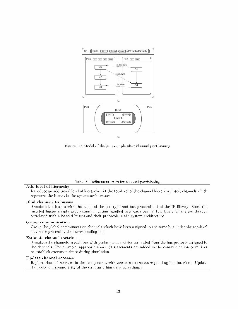
Figure 9: Example model after variable partitioning to a dedicated memory.ple, statements like x = data or data = f(y) are now transformed into statements like x = Cdata.read() orCdata.write(f(y)) instead. The variable channels encapsulate the communication with the memory behaviorwhich is listening on the other end to answer and handle those access requests.Figure 10 shows the case where the global variables v1 and data are mapped to local memories with a localcopy in each PE. Hence, behaviors in the PEs can access their local copies normally. However, in order to preservesemantics updated variable values have to be exchanged at synchronization points among PEs. Variable valuesare communicated over two global message-passing channels, Cv1 and Cdata. At synchronization barriers, codeis added that transfers new values from producers to consumers using the message-passing primitives of these twochannels.In both cases, global channels are not touched during the variable partitioning process. In the re�ned modelafter variable partitioning that has been obtained by following rules in Table 4, communication between PEs ishandled exclusively over channels and no global variables exist any longer.3.2.5 Channel PartitioningIn order to re�ne the abstract communication between components, the global channels need to be mapped ontothe allocated busses in the target architecture. This is achieved by grouping and encapsulating global channelsin the additional channels representing the system busses.In other words, abstract channels are partitioned into groups which are assigned to allocated bus channels.Later, during communication synthesis, these virtual bus channels will be re�ned into time-accurate modelsaccording to the selected bus protocols. However, at this point, the virtual bus channels are simply annotatedwith the type and name of the bus protocol in the IP library.Figure 11 shows how channel partitioning is performed in our example. Due to the simplicity of this example,channel partitioning here is easy. Since we have to connect only two PEs, we allocate one system bus between thetwo PEs, represented by the channel Bus0. All the channels are assigned to this bus, as shown in Figure 11(a),and all channel accesses in the leaf behaviors are replaced with accesses to this bus channel.The general re�nement rules for channel partitioning, explained in Table 5, are similar to the rules for behaviorpartitioning. Instead of introducing structure to the computational part of the system, channel partitioningintroduces structure to the communication part. 11

(a)
(b)
PE0 PE1
B7
B3
B1B6
B4
PE0 PE1
sync B1_syn B4_synB0 Cv1 Cdata
B4_done
v1, B1_done
sync
B1_syn
B4_syn
Cv1
Cdata
v2 v3 datav1 v1 data
data, sync
Figure 10: Example model after variable partitioning to local memories.Table 4: Re�nement rules for variable partitioning.Move variables into componentsAccording to the selected partition, move variables into the (memory or processing) components to whichthey have been assigned.Add communication channelsFor each variable add a global communication channel. In case a variable has been mapped to a dedicatedserver component, add a channel for communication with the memory server and connect all componentsaccessing the variable to that channel. In case a local copy of a variable is kept in each component, adda message-passing channel for exchange of updated values.Update variable accessesFor PEs with no local copy of a variable, replace all variable accesses with read() and write() callsto the corresponding channel. Otherwise, replace with accesses to local copy and add code at eachsynchronization point (wait) to send or receive updated variable values over the corresponding message-passing channel, in case the local copy was modi�ed before or will be needed after synchronization,respectively. In both cases, update ports and connectivity accordingly.Optimize communication and synchronizationOptimize variable communication by merging it with any existing communication and/or synchronization.For optimization, remove communication channels and corresponding code if variable is accessed onlyinside the assigned component. 12
(a)
(b)
PE0 PE1
B7
B3
B1B6
B4
PE0 PE1
B0 Bus0 sync B1_syn B4_synCv1 Cdata
sync
B1_syn B4_syn
Cv1 Cdata
Bus0
B4_done
v2 v3 datav1 v1 data
v1, B1_done
data, sync
Figure 11: Model of design example after channel partitioning.Table 5: Re�nement rules for channel partitioning.Add level of hierarchyIntroduce an additional level of hierarchy. At the top-level of the channel hierarchy, insert channels whichrepresent the busses in the system architecture.Bind channels to bussesAnnotate the busses with the name of the bus type and bus protocol out of the IP library. Since theinserted busses simply group communication handled over each bus, virtual bus channels are therebycorrelated with allocated busses and their protocols in the system architecture.Group communicationGroup the global communication channels which have been assigned to the same bus under the top-levelchannel representing the corresponding bus.Estimate channel metricsAnnotate the channels in each bus with performance metrics estimated from the bus protocol assigned tothe channels. For example, appropriate wait() statements are added in the communication primitivesto establish execution times during simulation.Update channel accessesReplace channel accesses in the components with accesses to the corresponding bus interface. Updatethe ports and connectivity of the structural hierarchy accordingly.
13

3.2.6 Architecture ModelThe task of architecture exploration is completed after allocation, partitioning and scheduling. In the SpecCmethodology, the designer determines the sequence of allocation and partitioning tasks, which usually containsseveral iterations. The designer repeats these steps based on his experience and on the quality metrics obtainedwith the estimation tools. This designer-driven design space exploration is easily possible in the SpecC environ-ment, because all parts of the system and all models are captured in the same language. This is unlike otherenvironments where, for example, translating C code to VHDL and vice versa must be performed and veri�ed.This design space exploration contributes to the attainment of a \good" system architecture and ultimately toan optimized implementation of the design, with good performance and lower costs.As a result of architecture exploration, the initial speci�cation model of the design has been re�ned into thearchitecture model, which accurately re ects the system architecture. Each component and each bus in thereal system is represented by a corresponding top-level behavior or top-level channel in the design model.The architecture model is an abstract model of the system under design, which accurately re ects the function-ality and the overall structure of the �nal implementation. The model is annotated with estimation results forquality assessment during simulation. However, at this point, the model is not yet accurate in terms of cycle-truetiming and communication, since execution times and delays have been estimated for all behaviors in the PEsand all channels in the busses. Assuming that the estimated execution times for the leaf behaviors have beeninserted into their code in form of waitfor statements, the architecture model will re ect these timing delays inthe simulation when it is executed.The architecture model for the design example resulting from the last partitioning step is shown in Figure 11.Figure 12 shows the corresponding SpecC code. As with the code for the original speci�cation model (Figure 3),only the top levels of the hierarchy are listed. An additional level in the behavior and channel hierarchy (componentbehaviors PE0 and PE1, and bus channel Bus0, respectively) is inserted. The code for synchronization ofbehaviors between components is implemented in separate control behaviors B1 done, B1 ctrl, B4 done andB4 ctrl. The control behaviors also contain the code for exchanging updated variable values over message-passingchannels (Figure 14) at those synchronization points.Also, due to the optimizations described in Section 3.2.4, synchronization and message-passing is mergedwherever possible. For example, synchronization for B1 is combined with the message-passing of the updatedvalue of v1 inside behaviors B1 ctrl and B1 done. This eliminates the need for the synchronization channel B1 synshown in Figure 11. Similarly, the sync channel is eliminated by merging synchronization between behaviors B6and B4 with the communication of the updated data value (see Figure 13).Note that the channels for exchanging updated variable values have standard message-passing semantics (Fig-ure 14). Therefore, they are generally available as part of the SpecC communication library.The main characteristic features of the SpecC architecture model are summarized in Table 6.3.3 Communication SynthesisThe purpose of communication synthesis is to resolve the abstract communication behavior in the virtualbusses of the architecture model through a series of re�nements which will lead to an implementation of thatcommunication over actual wires, and which will include accurate timing information.During communication synthesis, the virtual, abstract communication used in the architecture model is replacedwith real communication protocols implemented on the system busses. In other words, the virtual busses in thearchitecture model are replaced with actual busses and their protocols which are selected during architectureallocation. An application layer that implements the required abstract communication semantics over the nativeprotocols is generated and inserted in the design model on top of the native bus protocols. For incompatiblebus protocols, transducers are inserted into the system model to bridge the gap between the di�erent protocols.Finally, the communication protocols are implemented in software and hardware by inlining the communicationcode into the PEs.In the SpecC methodology, communication synthesis consists of three tasks, namely, protocol insertion, trans-ducer synthesis, and protocol inlining. 14

behavior PE0( IBus0 bus0 ) fint v1 , v2 , v3 , data ;B1 ct r l b 1 c t r l ( v1 , bus0 ) ;B6 b6( v1 , data , v3 , bus0 ) ;5 B7 b7( v3 , v2 ) ;B4 c t r l b 4 c t r l ( bus0 ) ;B3 b3( v2 ) ;void main(void ) f10 b1 c t r l . main ( ) ;b6 . main ( ) ;b7 . main ( ) ;b 4 c t r l . main ( ) ;b3 . main ( ) ;15 gg ;behavior PE1( IBus0 bus0 ) fint v1 , data ;20 B1 b1( v1 ) ;B1 done b1 done ( v1 , bus0 ) ;B4 b4( v1 , data , bus0 ) ;B4 done b4 done ( bus0 ) ;25 void main(void ) fb1 . main ( ) ;b1 done . main ( ) ;b4 . main ( ) ;b4 done . main ( ) ;30 gg ;behavior B0() fBus0 bus0 ;35 PE0 pe0 ( bus0 ) ;PE1 pe1 ( bus0 ) ;void main(void ) fpar f40 pe0 . main ( ) ;pe1 . main ( ) ;ggg ; Figure 12: SpecC code for architecture model of design example.15
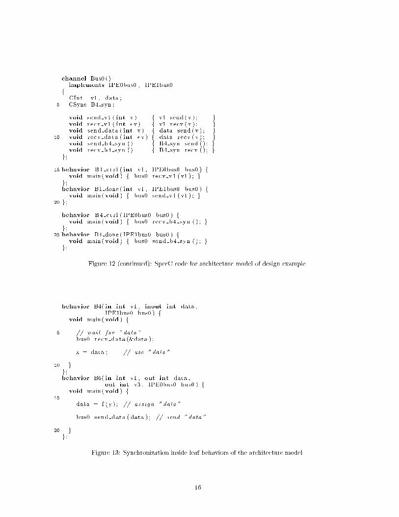
channel Bus0 ()implements IPE0bus0 , IPE1bus0f CInt v1 , data ;5 CSync B4 syn ;void send v1 ( int v ) f v1 . send ( v ) ; gvoid recv v1 ( int � v ) f v1 . recv ( v ) ; gvoid send data ( int v ) f data . send ( v ) ; g10 void recv data ( int � v ) f data . recv ( v ) ; gvoid send b4 syn ( ) f B4 syn . send ( ) ; gvoid recv b4 syn ( ) f B4 syn . recv ( ) ; gg ;15 behavior B1 ct r l ( int v1 , IPE0bus0 bus0 ) fvoid main(void ) f bus0 . recv v1 ( v1 ) ; gg ;behavior B1 done ( int v1 , IPE1bus0 bus0 ) fvoid main(void ) f bus0 . send v1 ( v1 ) ; g20 g ;behavior B4 ct r l ( IPE0bus0 bus0 ) fvoid main(void ) f bus0 . recv b4 syn ( ) ; gg ;25 behavior B4 done ( IPE1bus0 bus0 ) fvoid main(void ) f bus0 . send b4 syn ( ) ; gg ; Figure 12 (continued): SpecC code for architecture model of design example.behavior B4( in int v1 , inout int data ,IPE1bus0 bus0 ) fvoid main(void ) f. . .5 // wait for " data "bus0 . recv data (&data ) ;. . .x = data ; // use " data ". . .10 gg ;behavior B6( in int v1 , out int data ,out int v3 , IPE0bus0 bus0 ) fvoid main(void ) f15 . . .data = f ( y ) ; // ass ign " data ". . .bus0 . send data ( data ) ; // send " data ". . .20 gg ; Figure 13: Synchronization inside leaf behaviors of the architecture model.16

interface ISendInt fvoid send ( int v ) ;g ;interface IRecvInt f5 void recv ( int � v ) ;g ;channel CInt ()implements ISendInt , IRecvInt10 f int buf ;bool val id = fa lse ;event e ;15 void send ( int v ) fbuf = v ;va l id = true ;notify ( e ) ;g20 void recv ( int � v ) fi f ( ! va l id ) wait ( e ) ;� v = buf ;va l id = fa lse ;g25 g ; Figure 14: SpecC code for message-passing channel.Table 6: Architecture model guidelines.Create high-level structureThe top-level behaviors and channels represent the components and busses of the system architecture andtheir connectivity corresponds to the structure of the architecture. Behaviors grouped under the top-levelbehaviors specify the functionality (and storage) to be implemented on the corresponding component.Similarly, channels grouped under the top-level channels represents the communication to be implementedover the corresponding system bus.Sequentialize component functionalityThe behavior hierarchy inside the component behaviors is purely sequential, i.e. there are no parallel orpipelined behavior types. Parallelism is available only at the top-level, where all the component behaviorsrun concurrently.Specify global communicationThe bus channels exclusively contain abstract channels for directed communication of data values, i.e.there are no variables and random-access storage inside the bus channels.Annotate estimated metricsBehaviors and channels are annotated with their estimated design metrics for the components and bussesto which they are mapped, respectively. For simulation purposes, appropriate delay statements are addedto the behaviors and channels. 17

(a)
(b)
PE0 PE1
B7
B3
B1B6
B4
PE0 PE1
B0 Bus0
Bus0
B4_done
v1, B1_done
v2 v3 datav1 v1 data
Protocol
Protocol
data, sync
Figure 15: Model of design example after protocol insertion.3.3.1 Protocol InsertionThe designer selected the appropriate communication protocol for the system busses during the allocation task ofarchitecture exploration. Now, the virtual busses in the architecture model are re�ned into hierarchical channelswhich implement the required communication functionality over the actual wires of the bus. Communication isimplemented in two layers. The low-level layer is a channel that provides the native communication primitivesof the actual bus protocol. On top of that, an application layer implements the abstract communication over thelow-level bus protocol, for example by sizing the complex data types used in the application into blocks that canbe transported over the bus.Low-level bus protocol speci�cations are taken out of a protocol library and are written in the SpecC languagein terms of channel primitives that supply common interface function calls to facilitate reuse. For example, agiven VME bus description will supply send() and receive() as would the PCI speci�cation. In this way, we caneasily interchange protocols (as channels) and perform some simulation to obtain performance estimates. Later,the remote procedure calls (RPCs) to the channels will be replaced by local I/O instructions for software, or byadditional behavior to be synthesized for hardware entities.This process can be either manual or automatic. The cost of manual re�nement is still lower than that of thetraditional way, since, on account of the abstraction provided by the channel construct, the user does not have tobother with issues like detailed timing. Automatic re�nement will generate code for the application layer whichassembles high-level messages from low-level messages, or vice versa.Figure 15 shows this re�nement (summarized in Table 7) for our example. According to the target protocolallocated during architecture exploration, a bus protocol Protocol, such as the PCI bus, is inserted in order tocarry out the communication between the behaviors. The methods of the virtual bus Bus0 are re�ned to use themethods of the bus protocol encapsulated in the channel Protocol. Figure 15(b) shows how the channel hierarchydirectly re ects the layers of the communication between the PEs.3.3.2 Transducer SynthesisThe previous section on protocol insertion assumed that all components are synthesizable and therefore that laterthe communication layers can be inlined into the components, where they would be synthesized together with theother functionality to implement the required protocols at their interfaces.18
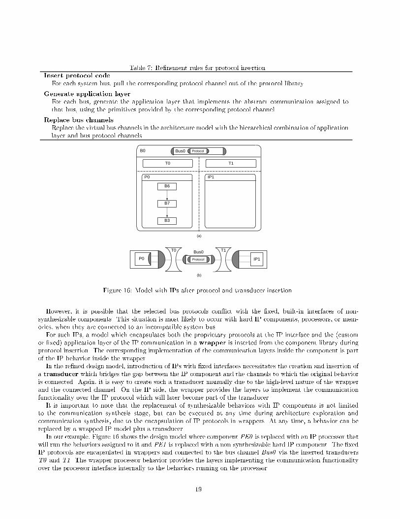
Table 7: Re�nement rules for protocol insertion.Insert protocol codeFor each system bus, pull the corresponding protocol channel out of the protocol library.Generate application layerFor each bus, generate the application layer that implements the abstract communication assigned tothat bus, using the primitives provided by the corresponding protocol channel.Replace bus channelsReplace the virtual bus channels in the architecture model with the hierarchical combination of applicationlayer and bus protocol channels.
(b)
(a)
T0 T1
IP1
IP1
T0 T1
B0 Bus0
P0
P0
B7
B3
B6
Bus0
Protocol
Protocol
Figure 16: Model with IPs after protocol and transducer insertion.However, it is possible that the selected bus protocols con ict with the �xed, built-in interfaces of non-synthesizable components. This situation is most likely to occur with hard IP components, processors, or mem-ories, when they are connected to an incompatible system bus.For such IPs, a model which encapsulates both the proprietary protocols at the IP interface and the (customor �xed) application layer of the IP communication in a wrapper is inserted from the component library duringprotocol insertion. The corresponding implementation of the communication layers inside the component is partof the IP behavior inside the wrapper.In the re�ned design model, introduction of IPs with �xed interfaces necessitates the creation and insertion ofa transducer which bridges the gap between the IP component and the channels to which the original behavioris connected. Again, it is easy to create such a transducer manually due to the high-level nature of the wrapperand the connected channel. On the IP side, the wrapper provides the layers to implement the communicationfunctionality over the IP protocol which will later become part of the transducer.It is important to note that the replacement of synthesizable behaviors with IP components is not limitedto the communication synthesis stage, but can be executed at any time during architecture exploration andcommunication synthesis, due to the encapsulation of IP protocols in wrappers. At any time, a behavior can bereplaced by a wrapped IP model plus a transducer.In our example, Figure 16 shows the design model where component PE0 is replaced with an IP processor thatwill run the behaviors assigned to it and PE1 is replaced with a non-synthesizable hard IP component. The �xedIP protocols are encapsulated in wrappers and connected to the bus channel Bus0 via the inserted transducersT0 and T1. The wrapper processor behavior provides the layers implementing the communication functionalityover the processor interface internally to the behaviors running on the processor.19

(a)
(b)
PE0 PE1
B7
B3
B1B6
B4
B0
B4_done
v1, B1_done
v2 v3 datav1 v1 data
data, sync
PE0 PE1
dat adr ctrl en
dat
adr
ctrl
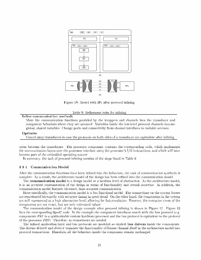
enFigure 17: Model after protocol inlining.As part of protocol insertion described in Section 3.3.1, transducer insertion and synthesis consists of the stepslisted in Table 8. Table 8: Re�nement rules for transducer synthesis.Insert transducersInsert transducer behaviors between component behaviors and bus channels that have incompatible pro-tocols on their ports.Encapsulate with wrappersReplace the component behaviors with their wrapped equivalents that encapsulate the IP interface pro-tocols.Synthesize transducer codeCreate code inside the transducer behaviors which performs a one-to-one mapping of communicationprimitives on one side to corresponding primitives on the other side.3.3.3 Protocol inliningDuring the �nal task of protocol inlining, methods located in the channels and wrappers are moved into theconnected behaviors, where they will be synthesized together with the rest of the component's functional (com-putational) behavior. The communication functionality is thereby included in the behaviors. Protocol inliningexposes the variables encapsulated inside the protocol channel, which then represent the wires of the systembusses. The port interfaces of the behaviors are therefore composed of bit-level signals, as compared to theabstract function calls before inlining was done.Figure 17 shows our example with synthesizable behaviors after inlining of the methods of both channels, Bus0and Protocol, into the behaviors. After this protocol inlining, the protocol channel variables dat, adr, ctrl, and enare exposed and serve as interconnection wires between the accordingly created ports of the components.Finally, Figure 18 shows the model with the IP components after protocol inlining is performed. Here, themethods from all the channels and wrappers are inlined into the transducers which communicate with the IPsvia proprietary busses. Again, the bus variables dat, adr, ctrl, and en are exposed and serve as interconnection20
(b)
(a)
IP1
T0 T1
B0
P0
B7
B3
B6
T0 T1
IP1
dat adr ctrl en
P0
ctrl0 ctrl1
ctrl0 dat0 ctrl1 dat1
dat1dat0
dat
adr
ctrl
enFigure 18: Model with IPs after protocol inlining.Table 9: Re�nement rules for inlining.Inline communication methodsMove the communication functions provided by the wrappers and channels into the transducer andcomponent behaviors where they are accessed. Variables inside the low-level protocol channels becomeglobal, shared variables. Change ports and connectivity from channel interfaces to variable accesses.OptimizeCancel away transducers in case the protocols on both sides of a transducer are equivalent after inlining.wires between the transducers. The processor component contains the corresponding code, which implementsthe communication layers over the processor interface using the processor's I/O instructions, and which will laterbecome part of the embedded operating system.In summary, the task of protocol inlining consists of the steps listed in Table 9.3.3.4 Communication ModelAfter the communication functions have been inlined into the behaviors, the task of communication synthesis iscomplete. As a result, the architecture model of the design has been re�ned into the communication model.The communication model is a design model at a medium level of abstraction. As the architecture model,it is an accurate representation of the design in terms of functionality and overall structure. In addition, thecommunication model features bit-exact, time accurate communication.More speci�cally, the communication model is a bus functional model. The transactions on the system bussesare represented bit-exactly with accurate timing in great detail. On the other hand, the components in the systemare still represented at a high abstraction level, allowing for fast simulation. However, the execution times of thecomponents are not exact, but are only estimated values.The communication model of the design example after protocol inlining is shown in Figure 17. Figure 19lists the corresponding SpecC code. In the example the component interfaces match with the bus protocol (e.g.components PE1 is a synthesizable custom hardware processor and the bus protocol is equivalent to the protocolof the processor PE0 ). Therefore, no transducers are needed.The inlined application layer and bus protocols are modeled as explicit bus drivers inside the components.The drivers driver0 and driver1 translate the functionality of former channel Bus0 in the architecture model intoprotocol transactions. Therefore, all the behaviors inside the component remain unchanged.21

behavior PE0( inout bit [ 15 : 0 ] dat , out bit [ 15 : 0 ] adr ,out bit [ 1 : 0 ] c t r l , out event en ) fint v1 , v2 , v3 , data ;CDriver0 dr iver0 ( dat , adr , c t r l , en ) ;5 B1 ct r l b 1 c t r l ( v1 , dr iver0 ) ;B6 b6( v1 , data , v3 , dr iver0 ) ;B7 b7( v3 , v2 ) ;B4 c t r l b 4 c t r l ( dr iver0 ) ;B3 b3( v2 ) ;10 void main(void ) fb1 c t r l . main ( ) ;b6 . main ( ) ;b7 . main ( ) ;15 b4 c t r l . main ( ) ;b3 . main ( ) ;gg ;20 behavior PE1( inout bit [ 15 : 0 ] dat , in bit [ 15 : 0 ] adr ,in bit [ 1 : 0 ] c t r l , in event en ) fint v1 , data ;CDriver1 dr iver1 ( dat , adr , c t r l , en ) ;B1 b1( v1 ) ;25 B1 done b1 done ( v1 , dr iver1 ) ;B4 b4( v1 , data , dr iver1 ) ;B4 done b4 done ( dr iver1 ) ;void main(void ) f30 b1 . main ( ) ;b1 done . main ( ) ;b4 . main ( ) ;b4 done . main ( ) ;g35 g ;behavior B0() fbit [ 15 : 0 ] dat , adr ;bit [ 1 : 0 ] c t r l ;40 event en ;PE0 pe0 ( dat , adr , c t r l , en ) ;PE1 pe1 ( dat , adr , c t r l , en ) ;void main(void ) f45 par fpe0 . main ( ) ;pe1 . main ( ) ;gg50 g ; Figure 19: SpecC code for communication model of design example.22

channel CDriver0 ( inout bit [ 15 : 0 ] dat , out bit [ 15 : 0 ] adr ,out bit [ 1 : 0 ] c t r l , inout event en )implements IPE0bus0f5 CBusMaster bus ( dat , adr , c t r l , en ) ;void recv v1 ( int � v ) fbus . IntA ( ) ; // wait for i n t e r r up t� v = bus . readBus (ADDR V1) ; // bus read cyc l e10 � v = � v j ( bus . readBus (ADDR V1) << 16 ) ;gvoid send data ( int v ) f// bus wri te cyc l e15 bus . writeBus ( v & 0xFFFF, ADDRDATA) ;bus . writeBus ( v >> 16 , ADDRDATA) ;gvoid recv b4 syn ( ) f20 bus . IntB ( ) ; // wait for i n t e r r up tgg ;channel CDriver1 ( inout bit [ 15 : 0 ] dat , out bit [ 15 : 0 ] adr ,25 out bit [ 1 : 0 ] c t r l , inout event en )implements IPE0bus1f CBusSlave bus ( dat , adr , c t r l , en ) ;30 void send v1 ( int v ) fio . raiseA ( ) ; // ra i s e i n t e r r up t// bus wri te cyc l ebus . putBus ( v & 0xFFFF, ADDR V1) ;bus . putBus ( v >> 16 , ADDR V1) ;35 gvoid recv data ( int � v ) f� v = bus . getBus (ADDRDATA) ; // bus read cyc l e� v = � v j ( bus . getBus (ADDRDATA) << 16 ) ;40 gvoid send b4 syn ( ) fio . raiseB ( ) ; // ra i s e i n t e r r up tg45 g ; Figure 19 (continued): Communication model, bus drivers.23
In comparison to the architecture model presented in Section 3.2.6, the additional characteristics of the com-munication model are listed in Table 10.Table 10: Communication model guidelines.Implement bus functionalityAt the top level, the behaviors which represent the components of the system architecture communicatevia a set of shared variables which represent the wires of the system busses in the target architecture.Annotate bus timingThe communication between components over their interfaces and the bus wires is modeled with accuratetiming whereas the (purely sequential) behavior inside the components is at the functional level withannotated estimated delays for simulation.3.4 BackendCommunication synthesis, as the last step in the synthesis ow, generates the hand-o� model for our system.This model is then further re�ned using traditional backend tools as shown in Figure 1.It is the task of the backend to create an optimized implementation for each particular component in thedesign model. More speci�cally, the custom hardware and transducer components need to be implemented by abehavioral hardware synthesizer and the software components need to be compiled for the particular processor.After inlining, the communication functionality has become part of the software (bus drivers in the operatingsystem) and hardware/transducer (communication FSMDs) components, and thus will be implemented togetherwith the other parts, possibly employing speci�c optimizations.As a result of the backend process, the �nal implementation model of the system is created. The implementationmodel will then be used for manufacturing of the system. It is a cycle-accurate RTL description of both thecomputation and communication in the system.3.4.1 Software CompilationC code for each of the allocated processors in the target architecture is created from the communication model.Retargetable compilers or special compilers for each of the di�erent processors are then used to compile the Ccode into instructions for the target processor.In the implementation model, the processor behaviors are then replaced with a cycle-accurate description of thetarget processor executing the generated assembly code. For example, an existing instruction set simulator(ISS) of the processor can be hooked into the SpecC implementation model, provided that the simulator supportsa suitable C programming interface.3.4.2 Hardware SynthesisThe hardware portion of the communication model consists of synthesizable, behavioral models in SpecC. For thebehavior hierarchy in the SpecC description, C (or VHDL) code can be created, which is then synthesized usingstandard high-level synthesis (HLS) tools. Note that the translation of the SpecC model into synthesizable C(or VHDL) is straightforward, since the component models are free of any special SpecC constructs at this point.High-level synthesis creates a behavioral or structural RTL model of the hardware components in the form ofscheduled register-transfer code or a netlist of RTL components, respectively. This structural or behavioral RTLdescription can then be modeled in SpecC, to be included in the implementation model for �nal cosimulation, forexample.3.4.3 Implementation ModelAs a result of hardware synthesis and software compilation for each component in the communication model, the�nal implementation model of the design is generated. 24

The implementation model is the model with the lowest level of abstraction in the SpecC methodology.It is an accurate model of the design implementation in terms of functionality, structure, communication andtiming. Note that the implementation model re ects both bus-cycle accurate timing for the communication, aswell as clock-cycle accurate timing for the computation performed in the system.The implementation model di�ers from the previous communication model only within the synthesizable com-ponents. A software component is described in terms of an instruction set architecture, while a hardware com-ponent is described with a FSMD model or a RTL netlist, a control unit and a data path, or at least a scheduled(but not bound) description of the operations performed in each clock step. In summary, the implementationmodel is ready for manufacturing.Table 11 summarizes the main features of the implementation model, in comparison with the communicationmodel (Section 3.3.4). Table 11: Implementation model guidelines.Implement system bussesAs in the communication model, component behaviors communicate over shared variables representingthe wires of the system busses. Communication is modeled with accurate timing.Implement system componentsThe component behaviors are replaced with a cycle-accurate model of the component implementation.Hence, computation is modeled with accurate timing, too.4 SummaryWith the background of a specify-explore-re�ne paradigm, we have presented an IP-centric methodology for thecodesign of embedded systems. The SpecC methodology consists of a set of well-de�ned tasks and design modelswhich allow the easy insertion and reuse of intellectual property.More speci�cally, the design methodology starts with an executable speci�cation of the system under designand eventually creates an implementation model ready for manufacturing. The intermediate tasks of allocation,partitioning, scheduling, and communication synthesis are performed by the designer interactively, either manuallyor with the help of design automation tools. As explained in this chapter, each task is built upon well-de�nedmodels and transformations. Therefore, the new, re�ned models produced at each step will be automaticallygenerated by the corresponding re�nement tools. On the other hand, re�nement is driven by the decisions mademanually by the designer or automatically by a set of algorithms. In all cases, the designer can focus on thecritical design decisions while tools automate tedious exploration and re�nement tasks.The SpecC methodology is based on four well-de�ned design models of di�erent levels of abstraction: thespeci�cation model, the architecture model, the communication model, and the implementation model. With eachsuccessive model, more implementation details are introduced. The speci�cation model is purely functional withno timing at all. The architecture model represents the structure of the target architecture, and the functionality inthe components and on the busses is annotated with estimated delays. In the communication model, componentsare still functional (with annotated delays), but the communication over system busses is time accurate. Finally,the implementation model is cycle-accurate both in computation (components) and communication (interfacesand busses).Please note that because of the modularity of the SpecC model (\plug-and-play"), a design can also be easilyrepresented as a mixture of these models. This is especially useful if parts of a design are further re�ned as others,or if accuracy is only required for speci�c portions in the design model. For example, a mixture of communicationand implementation models, makes possible a cycle-accurate simulation of certain system components togetherwith bus-functional models for the rest of the system.References[AG96] K. Arnold and J. Gosling. The Java Programming Language. Addison-Wesley, 1996.25

[GVNG94] D. Gajski, F. Vahid, S. Narayan, and J. Gong. Speci�cation and Design of Embedded Systems. PrenticeHall, 1994.[Inc98] IEEE Inc. IEEE Standard VHDL Language Reference Manual. New York, 1998.[Sec90] X3 Secretariat. The C language. In X3J11/90-013, ISO Standard ISO/IEC 9899, Washington, DC,USA, 1990. Computer and Business Equipment Manufacturers Association.[Str97] K. Stroustrup. The C++ Programming Language. Addison-Wesley, 3rd edition, 1997.[TM91] D. Thomas and P. Moorby. The Verilog Hardware Description Language. Kluwer Academic Publish-ers, 1991.[ZDG97] J. Zhu, R. D�omer, and D. Gajski. Syntax and semantics of the SpecC language. In Proceedings of theSynthesis and System Integration of Mixed Technologies, Osaka, Japan, December 1997.
26