Embed Size (px)
Citation preview

VCA Headquarters 1 The Eastgate Office Centre
Eastgate Road Bristol, BS5 6XX United Kingdom
Switchboard: +44 (0) 117 951 5151
Main Fax: +44 (0) 117 952 4103 Email: [email protected]
Web: www.vca.gov.uk
EAK216610 An executive agency of the Department for Transport
THE UNITED KINGDOM VEHICLE APPROVAL AUTHORITY
COMMUNICATION CONCERNING THE APPROVAL GRANTED OF A TYPE OF ELECTRICAL/ELECTRONIC SUB-ASSEMBLY (1) WITH REGARD TO REGULATION NO: 10 AS AMENDED BY THE 02 SERIES OF AMENDMENTS
Approval No: 10R-035493 1. Make (trade name of manufacturer): Directed Electronics 2. Type and general commercial description(s): Avital 3001L (2009 SKU), 330V (427) and 514J
Siren 3. Means of identification of type, if marked on the vehicle/component/separate technical unit(1)
Sticker on base of unit 3.1 Location of that marking: On top of unit 4. Category of vehicle: Not applicable 5. Name and address of manufacturer:
Directed Electronics 1 Viper Way Vista, CA 92081 United States of America
6. In the case of components and separate technical units, location and method of affixing of the
ECE approval mark: Printed on sticker on top of unit 7. Address(es) of assembly plant(s):
Nutek No.167, Lane 235 BauChiau Road ShinDian City, Taipei County 231 Taiwan
UK Approval Auth
orit
y
25-Mar-10

ECE REGULATION NO: 10.03 STU
EAK216610 An executive agency of the Department for Transport
2
8. Additional information (where applicable): See Appendix 9. Technical service responsible for carrying out the tests: SGS UK Ltd 10. Date of test report: 2 March 2010 11. Number of test report: AUT130731/4/GH/10 12. Remarks (if any): See Appendix 13. Place: BRISTOL 14. Date: 25 MARCH 2010 15. Signature: A. W. STENNING
Head of Technical and Quality Group 16. The index to the information package lodged with the approval authority, which may be obtained
on request is attached. 17. Reason for extension: Not applicable
UK Approval Auth
orit
y
25-Mar-10

ECE REGULATION NO: 10.03 STU
EAK216610 An executive agency of the Department for Transport
3
Appendix to Type Approval Communication Certificate No: 10R-035493 concerning the type approval of an electrical/electronic sub-assembly under Regulation No: 10
1. Additional information 1.1. Electrical system rated voltage: 12V. pos/neg ground(1) 1.2 This ESA can be used on any vehicle type with the following restrictions: 12V. pos/neg ground(1) 1.2.1 Installation conditions, if any: Supplied with the Product 1.3 This ESA can be used only on the following vehicle types: Not applicable 1.3.1 Installation conditions, if any: Not applicable 1.4 The specific test method(s) used and the frequency ranges covered to determine immunity were: (Please specify precise method used from Annex 9): 20 to 2000MHx at 30 V/m free field 1.5 Approved/accredited laboratory (for the purpose of this Regulation) responsible for carrying out
the test: SGS UK Ltd 2. Remarks: None (1) Delete where inapplicable
UK Approval Auth
orit
y
25-Mar-10

REG 10.3 ANNEX 2B.
INFORMATION DOCUMENT
FOR TYPE-APPROVAL OF AN ELECTRIC/ELECTRONIC SUB-ASSEMBLY
WITH RESPECT TO ELECTRONMAGNETIC COMPATIBILITY
1. Make (trade name of manufacturer):Directed Electronics 2. Type: Avital 3001L (2009 SKU), 330V (427) & 514J Siren 3. Means of Identification of type, if marked on the component/separate technical unit:
Sticker on base of unit 3.1. Location of marking: On top of unit 4. Name and address of manufacturer:
Directed Electronics 1 Viper Way, Vista, CA 92081, USA.
Name and address of authorized representative, if any: Carl Huntington 120 Riverview Rd, Ewell, Epsom, Surrey, KT19 0JQ
5. In case of components and separate technical units, location and method of affixing
of the approval mark: Printed on Sticker on top of unit 6. Address(es) of assembly plant(s):
Nutek No.167, Lane 235, BauChiau Road, ShinDian City, Taipei County 231, Taiwan
7. This ESA shall be approved as a Component: 8. Any restrictions of use and conditions for fitting: See instructions with product 9. Electrical system rated voltage: V Pos/Neg Ground.12V Appendix 1.
Description of the ESA chosen to represent the type (electronic block diagram and list of main components constituting the ESA (e.g. make and type of microprocessor, crystal etc.).
Appendix 2.
Relevant test report(s) supplied by the manufacturer from a test laboratory accredited to ISO 17025 and recognized by the Approval Authority for the purpose of drawing up the type approval certificate.
UK Approval Auth
orit
y
25-Mar-10

© 2009 Directed Electronics, Vista, CA N3001L 2009-04
3001L Security Systeminstallation guide
NNoottee:: This product is intended for installation by a profes-sional installer only! Any attempt to install this product byany person other than a trained professional may result insevere damage to a vehicle’s electrical system and com-ponents.
N3001L_2009-04print.qxd 5/12/2009 11:14 AM Page 1
UK Approval Auth
orit
y
25-Mar-10

Bitwriter®, Code Hopping™, Doubleguard®, ESP™, FailSafe®, GhostSwitch™, Learn Routine™, Nite-Lite®, Nuisance Prevention® Circuitry,Revenger®, Silent Mode™, Soft Chirp®, Stinger®, Vehicle RecoverySystem®, VRS®, and Warn Away® are all Trademarks or RegisteredTrademarks of Directed Electronics.
Bitwriters with date code of 6A or older require an IC upgrade (p/n998M). Some Bitwriters with a date code of 6B do not require the ICupgrade. Refer to Tech Tip # 1112 for more information. Bitwriter 2compatible.
The Bitwriter® (p/n 998U) requires chip version 2.5 or newer to program this unit.
N3001L_2009-04print.qxd 5/12/2009 11:14 AM Page 2
UK Approval Auth
orit
y
25-Mar-10

© 2009 Directed Electronics i
ContentsWhat is new 3
What is included 3
Control module 3
Installation points to remember 4
Before you begin installation 4
After the install 5
Tools required 5
Deciding on component location 6
Control module 6
LED and Valet switch 7
Starter kill relay 7
Connecting your wires 8
Obtaining constant 12V 8
Find the 12V switch ignition wire 9
Find a parking light wire 10
Find the door pin switch circuit 11
Main harness wire guide 12
Main harness diagram 12
Main harness connection guide 13
Auxiliary harness wire guide 18
Auxiliary harness diagram 18
Keyless entry system types 21
Door lock harness wire guide 23
Plug-in harnesses 23
LED and Valet switch 23
Data port—Bitwriter 24
Four-pin optional sensor harness 24
RED wire 24
BLACK wire 24
BLUE, GREEN wires 24
Door lock learn routine 24
To learn lock: 25
To learn unlock 25
To exit the learn routine 26
On-board dual stage shock sensor 27
Shock Adjustment Mode: 27
Internal polarity jumper 29
Zones 29
Long term event history 30
Rapid resume logic 30
Feature programming 31
Feature programming routine 31
Once a feature is programmed 32
Accessing additional features 32
Accessing feature menu 2 32
Exiting feature programming 33
Bitwriter ONLY features 34
Feature menu 1 35
Feature menu 2 36
Troubleshooting 37
Wiring quick reference guide 40
N3001L_2009-04print.qxd 5/12/2009 11:14 AM Page i
UK Approval Auth
orit
y
25-Mar-10

ii
N3001L_2009-04print.qxd 5/12/2009 11:14 AM Page ii
UK Approval Auth
orit
y
25-Mar-10

© 2009 Directed Electronics 3
What is newThe shock sensor is pre-set, but can be fine-tuned with the Bitwriter(see page 34)
What is includedControl module 4-pin sensor harness
12-pin main harness Valet switch and LED
7-pin door monitor/ 3-pin door lock Aux harness harness
Control module
BITWRITER®PROGRAMMING
PORT
DEALERMASTER
CONTROL LOOP (NOT USED)
OPTIONALANTENNA/RECEIVER
PORT (NOT USED)
12-PINMAIN
HARNESS
VALETSWITCH
OPTIONALSENSOR
PORT
7-PIN DOOR MONITOR/AUX PORT
DOOR LOCK PORT
LED
10-AMPFUSE/JUMPER/
LIGHT FLASHACCESS
N3001L_2009-04print.qxd 5/12/2009 11:14 AM Page 3
UK Approval Auth
orit
y
25-Mar-10

4 © 2009 Directed Electronics
Installation points to rememberThis product represents many years of research and development. It isvery sophisticated and should be installed by experienced securityinstallers only. Please do not attempt installation of this product withoutreading this guide. The system has been designed to provide the ulti-mate in security, coupled with limitless convenience and expansionoptions.
Do not disconnect the battery if the vehicle has an anti-theft codedradio. If equipped with an airbag, avoid disconnecting the battery ifpossible.
IIMMPPOORRTTAANNTT!! Please read this entire installation guide beforebeginning the installation. The installation of this security sys-tem requires interfacing with many of the vehicle’s systems.Many new vehicles use low-voltage or multiplexed systemswhich can be damaged by low resistance testing devices,such as test lights or logic probes. Test all circuits with a high-quality digital multi-meter before making the connections.
IMMPPOORRTTAANNTT!! Many airbag systems will display a diagnos-tic code through their warning light after they lose power. Dis-connecting the battery requires this code to be erased, a pro-cedure that can require a trip to the dealer.s
Before you begin the installation
Check with the customer to determine the LED and Valet switchlocation.
Remove the domelight fuse. This prevents accidentally draining thebattery.
Roll down a window to avoid being locked out of the car.
N3001L_2009-04print.qxd 5/12/2009 11:14 AM Page 4
UK Approval Auth
orit
y
25-Mar-10

© 2009 Directed Electronics 5
After the install
Test all functions. The “Using Your System” section of the Owner’sGuide is very helpful when testing.
When testing, don’t forget that this system is equipped with Nuisance Pre-vention Circuitry. NPC™ can bypass both sensor zones, making them seemto stop working.
Carefully reassemble the under-dash trim panels.
Inspect the engine compartment for tools that may have been leftbehind.
Tools requiredThis is a general list of tools required to complete the installation of thissecurity system in most vehicles. Some vehicles may require additionaltools.
Digital multi-meter Nutdriver and/or socket set
Wire cutters/strippers Panel removal tool
Solderless terminal crimpers Drill bit set
Cordless power drill Phillips head screw-driver
Torx driver set Work light
N3001L_2009-04print.qxd 5/12/2009 11:14 AM Page 5
UK Approval Auth
orit
y
25-Mar-10

6© 2009 Directed Electronics
Deciding on component location
Control module
Never put the control module in the engine compartment!
The first step in hot-wiring a vehicle is removing the driver's side under-dash panel to access the starter and ignition wires. If the control moduleis placed just behind the driver's side dash it can easily be disconnect-ed.
When locating the control module, try to find a secure location that willnot require you to extend the harnesses’ wires (they are 1.5 meterslong). Keep it away from the heater core (or any other heat sources) andany obvious leaks.
Some good control module locations: Above the glove box, inside thecenter console, above the underdash fuse box, behind or below abovethe radio, etc.
N3001L_2009-04print.qxd 5/12/2009 11:14 AM Page 6
UK Approval Auth
orit
y
25-Mar-10

© 2009 Directed Electronics 7
LED and Valet switch
Things to remember when positioning the LED and Valet switch:
• The LED should be visible from bothsides and the rear of the vehicle, ifpossible.
• The LED and Valet switch should be atleast 1-1/2" clearance to the rear.
• It is easiest to use a small removablepanel, such as a switch blank or adash bezel. Remove it before drillingyour 5/16" hole.
IImmppoorrttaanntt!! Do NNoott use a step drill bit (unibit) for drilling the5/16” hole. It is recommended to use a 5/16” drill bit. Usecare to ensure the hole is drilled straight. Drilling at an anglecan cause product malfunction.
Starter kill relay
If the Starter Kill Relay or it’s connections are immediately visible uponremoval of the underdash panel, they can easily be bypassed.
Always make the relay and its connections difficult to notice from thefactory wiring. Exposed yellow butt connectors do not look like factoryparts, and will not fool anyone. For this reason, routing the starter killwires away from the steering column is recommended.
N3001L_2009-04print.qxd 5/12/2009 11:14 AM Page 7
UK Approval Auth
orit
y
25-Mar-10

8 © 2009 Directed Electronics
Connecting your wiresNow that you have decided where each component will be located,you’re going to find the wires in the car that the security system will beconnected to.
IImmppoorrttaanntt!! Do not use a 12V test light or logic probe to findthese wires! All testing described in this manual is describedusing a digital multimeter.
Obtaining constant 12V
We recommend two possible sources for 12V constant: The (+) terminalof the battery, or the constant supply to the ignition switch. Always installa fuse within 12 inches of this connection.
IImmppoorrttaanntt!! Do not remove the fuse holder on the red (H1/11)wire. It ensures that the control module has it’s own fuse, of theproper value, regardless of how many accessories are addedto the main power feed.
N3001L_2009-04print.qxd 5/12/2009 11:14 AM Page 8
UK Approval Auth
orit
y
25-Mar-10

© 2009 Directed Electronics 9
Finding the 12V switch ignition wire
The ignition wire is powered when the key is in the run or start position.This is because the ignition wire powers the ignition system (spark plugs,coil) as well as the fuel delivery system (fuel pump, fuel injection comput-er). Accessory wires, on the other hand, lose power when the key is inthe start position to make more current available to the starter motor. Usethe following procedure to find (+)12V with your multimeter.
1. Set to DCV or DC voltage (12V or 20V is fine).
2. Attach the (-) probe of the meter to chassis ground.
3. Probe the wire you suspect of being the ignition wire. The steeringcolumn harness or ignition switch harness is an excellent place tofind this wire.
4. Turn the ignition key switch to the run position. If your meter reads(+)12V, go to the next step. If it doesn’t, probe another wire.
5. Now turn the key to the start position. The meter display shouldstay steady, not dropping by more than a few tenths of a volt. If itdrops close to or all the way to zero, go back to step 3. If it stayssteady at (+)12V, you have found an ignition wire.
N3001L_2009-04print.qxd 5/12/2009 11:14 AM Page 9
UK Approval Auth
orit
y
25-Mar-10

10 © 2009 Directed Electronics
Finding a parking light wire
The parking light wire is often found near the switch. Many cars have theswitch built into the turn signal lever, and the parking light wire can befound in the steering column. The same wire is often available in the kickpanel or running board.
To find the (+) and (-) parking light wire with your multimeter.
1. Set to DCV or DC voltage (12V or 20V is fine).
2. To find a (+) circuit, attach (-) probe of the meter to ground. If you are looking for a (-) circuit, attach (+) probe of the meter to(+) 12V.
3. Probe the wire you suspect of being the parking light wire. Thearea near the headlight/parking light switch, or near the kickpanel, is an excellent area to start.
4. Turn on the parking lights. If your meter shows (+)12V, turn off theparking lights and make sure it goes back to zero.
5. With the meter at zero, turn the parking lights On, and using thedash light dimmer control, turn the brightness of the dash lights upand down.
If the meter changes more than a volt when using the dimmer, lookfor another wire. If it stays relatively close to (+)12V, you havefound your parking light wire.
N3001L_2009-04print.qxd 5/12/2009 11:14 AM Page 10
UK Approval Auth
orit
y
25-Mar-10

© 2009 Directed Electronics 11
Finding the door pin switch circuit
The best places to find the door switch wire are:
At the pin switch: When testing at the pin switch, check the wire toensure that it “sees” all the doors. Often, the passenger switch will coverall the doors even if the driver’s switch will not.
At the dome light: This may not be your best choice if the vehicle hasdelayed domelight supervision, but it will work in vehicles with complete-ly diode-isolated pin switches.
Often the door switch wires, described above, can also be found in thewindshield pillars, running boards or kick plates.
Use the following procedure to find the door pin switch wire with yourmultimeter.
1. Set to DCV or DC voltage (12V or 20V is fine).
2. In most cars, fasten the (+) probe of your meter to (+)12V constant.
3. Using meter, probe the wire you suspect of being the door triggerwire. If the meter reads (+)12V when any door is opened and themeter goes to 0 with the door closed, you have found a (-) triggerwire.
4. Fasten the (-) probe of your meter to ground and then using posi-tive probe check for positive Door Trigger. If your meter displays12V when the Door is opened and 0 when it is closed you havefound the (+) door trigger.
IImmppoorrttaanntt: Make sure the wire you use “sees” all the doors -some newer vehicles lack standard-type pinswitches. Thedome light in these vehicles is turned on when the door han-dle is lifted. There is usually a wire coming out of the door intothe kick panel to provide a (-) trigger for all doors.
N3001L_2009-04print.qxd 5/12/2009 11:14 AM Page 11
UK Approval Auth
orit
y
25-Mar-10

12 © 2009 Directed Electronics
Main harness wire connection guide
Main harness wiring diagram
RED/WHITE (-)200mA Auxiliary Channel/Delayed Accessory Output
RED (+) 12V Constant Power Input
BROWN (+)Siren Output
YELLOW (+)Ignition Input
BLACK (-) Chassis Ground Input
VIOLET (+) Door Trigger Input
BLUE (-) Instant Trigger (Hood and Trunk Pin)
GREEN (-) Door Trigger Input
BLACK/WHITE (-) 200mA Domelight Supervison Output
WHITE/BLUE No Function
WHITE (+)Default/(-) Light Flash Output
ORANGE (-)500mA Ground When Armed H1/1
H1/2
H1/3
H1/4
H1/5
H1/6
H1/7
H1/8
H1/9
H1/10
H1/11
H1/12
N3001L_2009-04print.qxd 5/12/2009 11:14 AM Page 12
UK Approval Auth
orit
y
25-Mar-10

© 2009 Directed Electronics 13
Main harness wiring guide
H1/1 ORANGE (-) 500 mA ground-when-armed output: This wire sup-plies a (-) ground as long as the system is armed. This output ceases assoon as the system is disarmed. This wire controls operation of the pre-wired starter kill relay and can be used to control other optional acces-sories.
NNoottee:: If connecting the orange wire to control another mod-ule, such as a 529T or 530T window controller, a 1 ampdiode (type 1N4004) will be required. Insert the diode asshown below.
IImmppoorrttaanntt!! Never interrupt any wire other than the starter wire.
N3001L_2009-04print.qxd 5/12/2009 11:14 AM Page 13
UK Approval Auth
orit
y
25-Mar-10

14 © 2009 Directed Electronics
H1/2 WHITE light flash output: As shipped, this wire should be connect-ed to the (+) parking light wire. It will supply a (+) 10A output. If the lightflash polarity fuse jumper inside the unit is moved to the opposite posi-tion (see Internal Jumpers), this wire supplies a (-) 10A output. This issuitable for driving (-)parking light wires.
H1/3 WHITE/BLUE no function.
H1/4 BLACK/WHITE (-) 200 mA domelight-supervision output:Connect this wire to the (optional) domelight supervision relay. The stan-dard system does not include this relay, it is an optional feature.
IImmppoorrttaanntt!! This output is only intended to drive a relay. It cannot be con-nected directly to the domelight circuit, as the output cannot support thecurrent draw of one or more bulbs.
LIGHT BULB
PARKING LIGHTRELAY OR SWITCH
(+) 12V WHITE H1/2(-) LIGHT FLASH OUTPUT
N3001L_2009-04print.qxd 5/12/2009 11:14 AM Page 14
UK Approval Auth
orit
y
25-Mar-10

© 2009 Directed Electronics 15
H1/5 GREEN (-) door trigger input: Most vehicles use negative doortrigger circuits. Connect the green wire to a wire which shows groundwhen any door is opened. In vehicles with factory delays on the dome-light circuit, there is usually a wire that is unaffected by the delay cir-cuitry.
H1/6 BLUE (-) instant trigger: This input will respond to a negativeinput with an instant trigger. It is ideal for hood and trunk pins and willreport on zone one.
N3001L_2009-04print.qxd 5/12/2009 11:14 AM Page 15
UK Approval Auth
orit
y
25-Mar-10
16© 2009 Directed Electronics
H1/7 VIOLET (+) door trigger input: This wire is used in vehicles thathave a positive (+) switched dome light circuit . Connect the violet wireto a wire that shows (+)12V when any door is opened and ground,when the door is closed
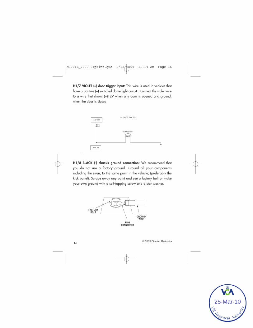
H1/8 BLACK (-) chassis ground connection: We recommend thatyou do not use a factory ground. Ground all your componentsincluding the siren, to the same point in the vehicle, (preferably thekick panel). Scrape away any paint and use a factory bolt or makeyour own ground with a self-tapping screw and a star washer.
N3001L_2009-04print.qxd 5/12/2009 11:14 AM Page 16
UK Approval Auth
orit
y
25-Mar-10

© 2009 Directed Electronics 17
H1/9 YELLOW (+) ignition input: Connect this wire to the (+)12V igni-tion wire. This wire must show (+)12V with the key in Run position andduring cranking. Take care to insure that this wire cannot be shorted tothe vehicle chassis at any point.
H1/10 BROWN (+) siren output: Connect this to the RED wire of thesiren. Connect the BLACK wire of the siren to (-) chassis ground, prefer-ably at the same point as the control module’s BLACK ground wire.
H1/11 RED (+)12V constant power input: Before connecting this wire,remove the supplied fuse. Connect to the battery positive terminal or theconstant 12V supply to the ignition switch.
Always use a fuse within 12 inches of the point you obtain (+)12V. Donot use the 15A fuse in the harness for this purpose. This fuse protectsthe module itself.
H1/12 RED/WHITE (-) 200mA auxiliary channel/delayed accessoryoutput: If programmed for an auxiliary output, this wire will provide a(-) pulse when the lock button on the factory transmitter is pressed twicewithin three seconds. This output can be used to control optional acces-sories. If programmed for delayed accessory output, this wire will pro-
N3001L_2009-04print.qxd 5/12/2009 11:14 AM Page 17
UK Approval Auth
orit
y
25-Mar-10

18 © 2009 Directed Electronics
vide (-) ground when the ignition is turned off and will continue to out-put (-) ground until a door is opened then closed. This can be used toenergize the accessory circuit in the vehicle to keep the radio and otheraccessories on after the ignition is turned off.
IImmppoorrttaanntt!! Never use this wire to drive anything but a relay ora low-current input! This transistorized output can only supply(-) 200 mA, and connecting directly to a solenoid, motor, orother high-current device will cause the module to fail.
Sensors and other triggers can be bypassed if this output is used to openthe vehicle trunk while the alarm is armed. See H2/5 Gray zone shunt-ing for programming and connection descriptions.
Auxiliary harness wire connectionguide
Auxiliary harness wiring diagram
YELLOW/BLACK Light Flash Monitor Input
VIOLET/BLACK No Function
GRAY (+) Trunk Release/Sensor Shunt Input
BLUE Disarm Input
RED Disarm Defeat Input
GREEN Arm Input
BROWN (-) Horn Honk OutputH2/1
H2/2
H2/3
H2/4
H2/5
H2/6
H2/7
N3001L_2009-04print.qxd 5/12/2009 11:14 AM Page 18
UK Approval Auth
orit
y
25-Mar-10

© 2009 Directed Electronics 19
Auxiliary harness wiring guide
H2/1 BROWN (-) horn honk output: This wire supplies a 200 mA (-)output that can be used to honk the vehicle’s horn. It provides a pulsedoutput when the security system is armed/disarmed and in the triggeredsequence or in panic mode. In most vehicle’s with (-) horn circuits thiswire can control the vehicle’s horn without adding a relay. If the vehiclehas a (+) horn circuit, an optional relay must be used to interface withthe vehicle’s horn circuit.
IImmppoorrttaanntt!! Never use this wire to drive anything but a relay ora low-current input! This transistorized output can only supply(-) 200 mA, and connecting directly to a solenoid, motor, orother high-current device will cause the module to fail.
H2/2 GREEN for arm input: Connect this GREEN wire to a wire thatchanges state when the doors are locked using the factory keyless entrytransmitter. This wire can accept a positive (+) or negative (-) input. Thevehicle’s power door lock motor wire is ideal.
H2/3 RED disarm defeat input: This wire is used to prevent the interiordoor lock switches from disarming the system. To determine the bestlocation to interface this wire, first test the operation of the remote key-less entry system.
When unlocking the doors with the factory remote transmitter, does thedriver’s door unlock first? Most vehicles operate this way. If this is thecase connect the RED wire to the passenger unlock motor wire. Whentesting this wire, it should show 12V (+) ONLY when the unlock buttonon the factory transmitter is pressed a second time to unlock the passen-ger doors. If the factory keyless entry system unlocks all of the doors atthe same time, it is recommended that the H2/7 YELLOW/BLACK wire
N3001L_2009-04print.qxd 5/12/2009 11:14 AM Page 19
UK Approval Auth
orit
y
25-Mar-10

20 © 2009 Directed Electronics
be used for disarm defeat input. The H2/3 wire connection is not requiredif using H2/7 YELLOW/BLACK as a disarm defeat wire.
H2/4 BLUE disarm input: Connect the BLUE wire to a wire that changesstate when the doors are unlocked using the factory keyless entry trans-mitter. If the factory transmitter unlocks the driver’s door first, the BLUEwire must be connected to the wire that changes state when the driver’sdoor is unlocked by itself. In this case, find the driver’s door unlock motorwire. In most vehicle’s this wire can be found in the driver’s kick panel.
H2/5 GRAY trunk release/sensor shunt input: This input is used tobypass the sensor inputs when the trunk is opened using the factory key-less entry system or trunk release relay while armed. When the systemreceives a (+) input on this wire, zones 1, 2 and 4 are bypassed for 3-seconds. If during that 3-seconds, ground is applied to the H1/6 BLUEwire then the alarm zones are bypassed (See Feature menu 1/8) andwill remain bypassed until the ground input is removed. This means thatwhen the trunk is open with the factory transmitter the only triggers thatremain active while the trunk is open are the doors and ignition. 3-sec-onds after the trunk is closed the bypassed zones again become active.
H2/6 VIOLET/BLACK no function.
H2/7 YELLOW/BLACK light flash monitor input: This input monitors thefactory system light flash output and can be used as a disarm defeatwire. Connect this wire to the light flash wire that flashes when the fac-tory transmitter is used. This may be a status LED, parking lights, reverselights, etc - depending on the vehicle type and manufacturer. The yel-low/black wire can accept a (+) positive or (-) negative input and shouldbe used when the factory keyless entry does not provide drivers priorityunlock.
N3001L_2009-04print.qxd 5/12/2009 11:14 AM Page 20
UK Approval Auth
orit
y
25-Mar-10

© 2009 Directed Electronics 21
Keyless entry systems—two types
There are two main types of keyless entry systems. Systems that unlockthe driver’s door first and Systems that unlock all doors at the same time.
drivers priority unlock
To test for this type of system unlock the door, by using the factoryremote. If the factory remote only unlocks the drivers door on the firstpress of unlock use the following diagram.
NNoottee:: It is often easy to access the passenger unlock wiregoing to the rear door motor on the driver’s side.
N3001L_2009-04print.qxd 5/12/2009 11:14 AM Page 21
UK Approval Auth
orit
y
25-Mar-10

22 © 2009 Directed Electronics
No priority—driver’s door unlock
This type of keyless entry system is common in import vehicles as well asmany Jeep vehicles. When unlocking the doors with the transmitter alldoors unlock at the same time. It is recommended to use H2/7 YEL-LOW/BLACK wire for Disarm Defeat instead of the H2/3 RED wire. Thisinput wire monitors the factory system light flash output. Connect thiswire to the light flash wire that flashes when the factory transmitter isused. This may be a status LED, parking lights, reverse lights, etc.,depending on the vehicle type and manufacturer. Do NOT connect thiswire to the domelight. This wire can accept a (+) positive or (-) negativeinput.
For installation, please refer to the diagram below.
H2/7 YEL/BLK
(NOT USED)
PARKING LIGHT RELAYOR SWITCH
PARKING LIGHT BULB
N3001L_2009-04print.qxd 5/12/2009 11:14 AM Page 22
UK Approval Auth
orit
y
25-Mar-10

© 2009 Directed Electronics 23
Door lock harness wire connectionguide
These door lock outputs are for Passive arming control of the factorydoor locks. They can also be used to control the door locks with theignition switch for vehicles that do not have this feature in the factoryRKE system.
The control module can control 2 common power door lock types with-out any additional parts. With certain vehicles, or if an actuator is to beinstalled, either a 451M Door Lock Relay Satellite or two relays will berequired. See www.directechs.com for TechTips document 1041.
Plug-in harnesses
LED and Valet switch
The LED and Valet switch should be accessible from the driver’s seat. TheValet switch plugs into the blue port on the side of the unit. Check forrear clearance before drilling a 5/16-inch hole and mounting theswitch. The LED switch operates at 2V DC and plugs into the white porton the side of the unit. Make sure the LED wires are not shorted toground, this will damage the LED.
BLUE (-)Unlock, (+) Lock Output
Not Used
GREEN (-) Lock, (+) Unlock Output H3/A
H3/B
H3/C
N3001L_2009-04print.qxd 5/12/2009 11:14 AM Page 23
UK Approval Auth
orit
y
25-Mar-10

24 © 2009 Directed Electronics
Data port—Bitwriter®
The black three-pin port can be used for programming the unit using theDirected Bitwriter, a hand held programming tool. The Bitwriter alsoallows programming of features that are not available in the featuremenus.
Four-pin optional sensor harness
RED wire
The red wire supplies constant power to the optional sensor.
BLACK wire
The black wire supplies ground to the optional sensor.
BLUE, GREEN wires
The blue and green wires are multiplex inputs. They are both tied to thesame zone. If an input of less than 0.8 seconds is supplied to either wirethe Warn-Away® response will occur. An input longer than 0.8 secondsto either wire will initiate the triggered sequence and report zone 4. Thisport can be used for optional sensors such as: the 506T—glass break-age sensor, or the 508D—field disturbance sensor.
N3001L_2009-04print.qxd 5/12/2009 11:14 AM Page 24
UK Approval Auth
orit
y
25-Mar-10

25
Door lock learn routineBefore the unit will respond to the factory remote keyless system, it mustlearn the polarity of the door lock wires. To learn the lock polarity:
It is important that all the INPUT signals to the control moduleare in the rest status state (no activity) before entering the learnroutine.
To learn lock:
Make sure the doors, hood and trunk are closed so the factory systemoperates as it would when the user is using it.
1. With all the doors, hood and trunk closed: Plug in all harnesses(12 pin harness plugs in last )
2. Within 5-seconds: Press and hold the Valet switch.The LED flashesonce.
3. Immediately press the lock button on the OEM transmitter. The LEDwill flash once confirming the lock was successfully learned thenwill light up solid.
To learn unlock:
4. Within 3-seconds: Press and release the Valet switch once thenpress and hold. The LED will flash twice.
5. Immediately press the unlock button on the OEM transmitter.
6. The LED will flash twice then light up solid confirming the unlockwas successfully learned.
7. Release the Valet switch.
8. Cycle the ignition switch to exit programming.
© 2009 directed electronics
N3001L_2009-04print.qxd 5/12/2009 11:14 AM Page 25
UK Approval Auth
orit
y
25-Mar-10

26 © 2009 Directed Electronics
If the lock/unlock learn was unsuccessful, unplug the 12 pin harness for15 seconds and re-attempt procedure.
The systems learn routine will only be active for ten seconds after powerup. If locks are not successfully learned unplug main 12 pin harness for15 seconds and re-attempt.
To exit the learn routine:
You can do ONE of the following:
Turn the ignition on.
Wait for 15 seconds.
Press the Valet switch too many times.
N3001L_2009-04print.qxd 5/12/2009 11:14 AM Page 26
UK Approval Auth
orit
y
25-Mar-10

© 2009 Directed Electronics 27
On-board dual stage shock sensorThere is a dual-stage shock sensor inside the control module. Adjustmentsare made via programming routine indicated below. Since the shock sen-sor does not work well when mounted firmly to metal, we recommendagainst screwing down the control module. The full trigger of the onboardshock sensor reports zone 2. See Table of Zones.
When adjusting the sensor, it must be in the same mounting locationafter the install is completed. Adjusting the sensor and then relocatingthe module requires readjustment.
The system must be disarmed. Doors and other protected entries must beclosed, and the ignition Off.
To enter Shock Adjustment Mode:
NNoottee:: Door locks must be learned prior to entering shock sen-sor adjustment mode.
Start with the system disarmed, and sit in the driver's seat. Make sureyou have the OEM remote and the ignition key.
1. Turn the ignition key switch on, then off, three times in three sec-onds: On, off, on, off, on, off.
2. The siren/horn sounds three short chirps or honks. The Status LEDwill blink to indicate the current setting.
3. The adjustment mode lasts for 20 seconds. If no adjustments aremade, the system exits the adjustment mode 20 seconds later. Toextend the time, press the Valet Switch (see note below).
4. To increase sensitivity, press the Unlock button on the OEM remote.To decrease sensitivity, press the Lock button.
N3001L_2009-04print.qxd 5/12/2009 11:14 AM Page 27
UK Approval Auth
orit
y
25-Mar-10

28 © 2009 Directed Electronics
When the sensitivity increases, two quick, short chirps/honks areheard. Decreased sensitivity is indicated by one quick chirp.
If maximum or minimum settings are reached, a long chirp/honkis added.
You can test the adjustment setting by striking the outside ofthe vehicle with varied force levels to trigger the sytem. Thesiren chirps to confirm that the system will trigger at that set-ting.
5. To exit the adjustment mode, turn on the key. Four quick, shortbeeps are heard. Then the Status LED will indicate the sensitivitylevel.
After impact sensor learn routine has been exited, the LED will confirmthe current impact sensor setting.
Important: Horn honks apply only if the hornwire is connected.
N3001L_2009-04print.qxd 5/12/2009 11:14 AM Page 28
UK Approval Auth
orit
y
25-Mar-10
© 2009 Directed Electronics 29
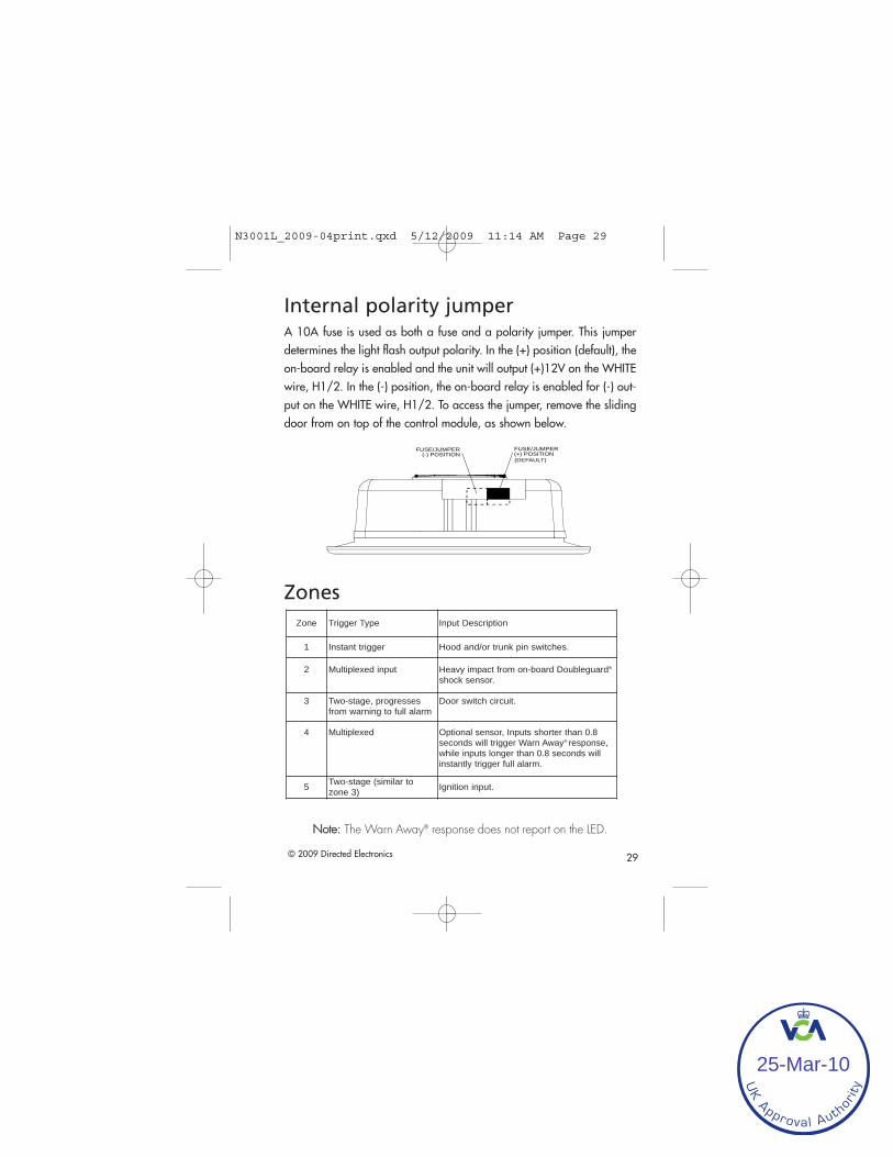
Internal polarity jumperA 10A fuse is used as both a fuse and a polarity jumper. This jumperdetermines the light flash output polarity. In the (+) position (default), theon-board relay is enabled and the unit will output (+)12V on the WHITEwire, H1/2. In the (-) position, the on-board relay is enabled for (-) out-put on the WHITE wire, H1/2. To access the jumper, remove the slidingdoor from on top of the control module, as shown below.
Zones
NNoottee:: The Warn Away® response does not report on the LED.
Zone Trigger Type Input Description
1 Instant trigger Hood and/or trunk pin switches.
2 Multiplexed input Heavy impact from on-board Doubleguard®
shock sensor.
3 Two-stage, progressesfrom warning to full alarm
Door switch circuit.
4 Multiplexed Optional sensor, Inputs shorter than 0.8seconds will trigger Warn Away® response,while inputs longer than 0.8 seconds willinstantly trigger full alarm.
5 Two-stage (similar tozone 3) Ignition input.
FUSE/JUMPER(-) POSITION
FUSE/JUMPER(+) POSITION(DEFAULT)
N3001L_2009-04print.qxd 5/12/2009 11:14 AM Page 29
UK Approval Auth
orit
y
25-Mar-10

30 © 2009 Directed Electronics
Long term event historyThe control module will store the last 2 triggers in memory that are noterased when the ignition is turned on. This can be helpful for troubleshooting false alarm reports. To access the event history use the follow-ing procedure.
1. With the ignition switch in the off position press and hold the Valetswitch.
2. While holding the Valet switch turn the ignition On.
3. Release the Valet switch.
4. Within 5-seconds, press and release the Valet switch.
The LED will flash in groups indicating the last two zones triggered. Forexample, if zone 2 and 3 were the last two zones to be triggered, theLED will flash two times followed by a pause and then flash three timesfollowed by a pause.
NNoottee:: The Warn Away® response does not report on the LED.
The Long Term Event History will exit if the ignition is turned off or thereis no activity for 60-seconds.
Rapid resume logicThe current state of the alarm will be stored in non-volatile memory. Ifpower is lost and then reconnected, the system will recall the stored statefrom memory (arm, disarm, and Valet mode).
N3001L_2009-04print.qxd 5/12/2009 11:14 AM Page 30
UK Approval Auth
orit
y
25-Mar-10

© 2009 Directed Electronics 31
Feature programmingThe feature programming routine is used to access and change any ofthe feature settings in the two menus below. The feature settings can beaccessed and changed by using one of the following:
The Valet switch to enter the feature programming routine.
Use of the Directed Electronics Bitwriter® is recommended.Expanded programming options are only available when using theDirected Electronics Bitwriter®.
NNoottee:: If Feature Programming Lockout is set to ON, all fea-tures will be locked and can OONNLLYY be accessed by using aBitwriter®.
To enter feature programming routine
1. Open a door.
2. Turn the ignition on and then off.
3. Close the door.
4. Within 5-seconds, press and HOLD the Valet switch. After 3-secondsthe siren/horn will sound once to indicate entry into feature menu 1. Toselect the second features menu, continue to hold the Valet switch untilthe siren/horn sounds twice. Once the desired menu is selected, releasethe Valet switch.
N3001L_2009-04print.qxd 5/12/2009 11:14 AM Page 31
UK Approval Auth
orit
y
25-Mar-10

32 © 2009 Directed Electronics
5. Within 5-seconds, press and release the Valet switch the number oftimes corresponding to the desired feature listed below. Then press theValet switch one more time and hold. The siren/horn will sound the num-ber of times equal to the feature number selected.
6. While holding the Valet switch, assign the selected feature to a factory button.
Press Lock for 1 short siren chirp/horn honk, or press Unlock for 2 shortsiren chirps/horn honks.
Once a feature is programmed
Other features can be programmed.
Other feature menu can be selected.
Learn Routine can be exited.
Accessing additional features
Release, then press and release the Valet switch the number of timesto advance from the feature just programmed to the next featuredesired.
Press and hold the Valet switch once more.
The siren chirps/horn honks to confirm the feature selected.
Important: Horn honks apply only if the hornwire is connected.
N3001L_2009-04print.qxd 5/12/2009 11:14 AM Page 32
UK Approval Auth
orit
y
25-Mar-10

© 2009 Directed Electronics 33
Accessing feature menu 2
Release, then press and hold the Valet switch.
After 3-seconds, the unit will advance to the next menu and thesiren/horn will sound 2 times to indicate feature menu 2 has beenentered.
Exiting feature programming
You can do ONE of the following:
Turn the ignition On.
No activity for 15-seconds.
Press and release the Valet switch too many times.
Important: Horn honks apply only if the hornwire is connected.
N3001L_2009-04print.qxd 5/12/2009 11:14 AM Page 33
UK Approval Auth
orit
y
25-Mar-10

34 © 2009 Directed Electronics
Bitwriter® ONLY features
Due to memory limitations for this system, the following features can onlybe programmed using Directed’s Bitwriter® programmer. Factory defaultsettings are shown in bold (left column).
*Feature only available if using optional antenna and non-OEM remote.
B-1 Shock Sensor Adjustment - programmable 0-16
B-2 Siren duration - 0 to 180 seconds
B-3 Channel 3* Validity Latched/Latched reset w/ign/lacth 30 sec-ond timed/2nd unlock/ delayed acc.
B-4 Forced passive arming ON Forced passive arming OFF
B-5 NPC ON NPC OFF
B-6 Panic with ignition OFF Panic with ignition ON
B-7 Dealer security features OFF Dealer security features ON
B-8 Transmitter programmingUNLOCKED
Transmitter programming LOCKED
B-9 Feature programmingUNLOCKED
Feature programming LOCKED
N3001L_2009-04print.qxd 5/12/2009 11:14 AM Page 34
UK Approval Auth
orit
y
25-Mar-10

© 2009 Directed Electronics 35
Feature menu 1
Factory default settings are shown in bold.
Feature steps 5 and 6 are related. Only if Auxiliary Output Enabled isselected in step 5 can either Auxiliary Output or Delayed AccessoryOutput be selected in step 6. Examples of this are where AuxiliaryOutput is used to provide a momentary 800mSec pulse on theRED/WHITE wire of the main harness. It may be used for opening thetrunk. (continued on next page.)
FeatureStep Lock Button (one chirp) Unlock Button (two chirps)
1 Active arming Passive arming
2 Chirps ON Chirps OFF
3 Door Trigger Error Chirp ON Door Trigger Error Chirp OFF
4 Ignition-Controlled Domelight ON Ignition-Controlled Domelight OFF
5 Panic Enabled (OEM upgrade) Auxiliary Output Enabled (OEM upgrade)
6 Auxiliary Output Delayed Accessory Output
7 Delayed Door Trigger Instant Door Trigger
8 Sensor shunt zones 1, 2 & 4 All zones
9 Siren Duration–30 seconds Siren Duration–60 seconds
10 Valet switch input: 1-pulse Valet switch input: 2-5 pulses
11Horn pulse honk duration 0.020seconds (does not affect full trig-ger pulse duration)
0.030, 0.040, 0.050 seconds
N3001L_2009-04print.qxd 5/12/2009 11:14 AM Page 35
UK Approval Auth
orit
y
25-Mar-10

36 © 2009 Directed Electronics
The delayed accessory output allows selected vehicle accessories toremain on (such as radio) when the ignition is turned off. This outputis active for 1 hour until a door is opened and closed - or the systemis armed using the factory remote transmitter.
Feature menu 2
Factory default settings are shown in bold.
*Feature only available if using optional antenna and non-OEM remote.
FeatureStep Lock Button (one chirp) Unlock Button (two chirps)
1 Ignition-Controlled Locking ON Ignition-Controlled Locking OFF
2 Ignition-Controlled UnLocking ON Ignition-Controlled Unlocking OFF
3 Active Locking Passive Locking
4 Door Lock Pulse Duration–0.8 sec. Door Lock Pulse Duration–3.5 sec.
5 Single Unlock Pulse Double Unlock Pulse
6* Channel 3: Validity Channel 3: Second Unlock
7 Code Hopping ON* Code Hopping OFF
N3001L_2009-04print.qxd 5/12/2009 11:14 AM Page 36
UK Approval Auth
orit
y
25-Mar-10

© 2009 Directed Electronics 37
Troubleshooting
Starter kill does not work:
Is the correct starter wire being interrupted? If the car starts when thestarter kill relay is completely disconnected, the wrong starter wire hasbeen cut and interrupted.
• Is the yellow wire connected to “true” ignition? Make sure this wireis connected to a wire that has power in the run and start positions.
• The starter kill goes active 1 minute after arming the alarm. Makesure you wait that time period before attempting to test.
The Valet switch does not work.
• Is it plugged into the correct socket? See the Valet Switch section ofthis guide.
• Is the H1/9 YELLOW wire properly connected? See PrimaryHarness (H1) Wire Connection Guide section of this guide.
• If the mounting of the switch is a tight fit it can cause the switch notto work properly. Make sure the hole size is drilled with a 5/16 drillbit.
Status LED does not work.
• Is the LED plugged into the small white port on the side of the con-trol unit? See LED and Valet Switch section of this guide.
N3001L_2009-04print.qxd 5/12/2009 11:14 AM Page 37
UK Approval Auth
orit
y
25-Mar-10

38 © 2009 Directed Electronics
Passive or Ignition controlled door locks operatebackwards.
• This unit has easily-reversed lock/unlock outputs. Recheck Doorlock harness outputs (H3) section, to see if you have reversedthese.
The siren chirps/horn honks when the unit enterspanic mode, but the confirmation chirps/honks donot work when locking and unlocking.
• Are the confirmation chirps/honks turned on in programming?See Feature Programming section.
• Is the unit in Valet mode.
• Is the horn pulse duration long enough? Some cars require alonger pulse on the horn wire for it to honk. (see features pro-gramming menu 1-11).
I can get into programming and change the featuresettings, but when I use the remote the settingsseem to change.
• Are you using a binary, master dealer remote? Remember, youcan program the settings using a master dealer remote. However,the unit will follow the dealer default settings when using a bina-ry remote to operate the system.
Door Lock Learn Routine does not learn door locks.
• Check connections to be sure everything is properly connected.Refer to the Keyless Entry Systems - Two Types section of this guide.
• Check the Door Lock Learn Routine section of this guide to ensurethe correct procedure is being used.
N3001L_2009-04print.qxd 5/12/2009 11:14 AM Page 38
UK Approval Auth
orit
y
25-Mar-10

© 2009 Directed Electronics 39
Door Lock Learn Routine does not work, the unitenters the learn routine then chirps/honks andexits.
• Some cars do not lock the doors when the door is open. For thesevehicles, to program the unit correctly the door needs to be closed.
Unit goes into Programming every time the ignition isturned off.
• The Valet switch is probably stuck in the down position. If the holefor the switch is too tight, the travel of the switch can be impaired andthe switch may stick in the down position. To allow the button to trav-el freely, the mounting hole must not be too tight.
N3001L_2009-04print.qxd 5/12/2009 11:14 AM Page 39
UK Approval Auth
orit
y
25-Mar-10

40
Wiring quick reference guide(D
eal
er
Mas
ter
Mo
de
On
ly)
Val
et
swit
ch
De
ale
r M
aste
rC
on
tro
l Lo
op
(No
t U
sed
)
© 2009 Directed Electronics
N3001L_2009-04print.qxd 5/12/2009 11:14 AM Page 40
UK Approval Auth
orit
y
25-Mar-10

N3001L_2009-04print.qxd 5/12/2009 11:14 AM Page 41
UK Approval Auth
orit
y
25-Mar-10

The company behind this system is Directed Electronics
Since its inception, Directed Electronics has had one purpose,to provide consumers with the finest vehicle security and carstereo products and accessories available. The recipient ofnearly 100 patents and Innovations Awards in the field of
advanced electronic technology.
Directed is ISO 9001 registered.
Quality Directed Electronics products are sold and servicedthroughout North America and around the world.
Call (800) 274-0200 for more information about our products and services.
Vista, CA 92081www.directed.com
© 2009 Directed Electronics - All rights reserved
N3001L_2009-04print.qxd 5/12/2009 11:14 AM Page 42
UK Approval Auth
orit
y
25-Mar-10

Model 330VOOwwnneerr’’ss GGuuiiddee
G427V_01-05.qxd 12/31/2004 12:44 PM Page 1
UK Approval Auth
orit
y
25-Mar-10

G427V_01-05.qxd 12/31/2004 12:44 PM Page 2
UK Approval Auth
orit
y
25-Mar-10

i© 2005 directed electronics, inc.
lliimmiitteedd lliiffeettiimmee ccoonnssuummeerr wwaarrrraannttyyDirected Electronics, Inc. promises to the original purchaser to repair or replace with acomparable reconditioned model any Directed Electronics, Inc. unit (hereafter the"unit"), excluding without limitation the siren, the remote transmitters, the associatedsensors and accessories, which proves to be defective in workmanship or material underreasonable use during the lifetime of the vehicle provided the following conditions aremet: the unit was professionally installed and serviced by an authorized DirectedElectronics dealer; the unit will be professionally reinstalled in the vehicle in which it wasoriginally installed by an authorized Directed Electronics dealer; and the unit is returnedto Directed Electronics, Inc., shipping prepaid with a legible copy of the bill of sale orother dated proof of purchase bearing the following information: consumer's name, tele-phone number and address; the authorized dealers name, telephone number and address;complete product description, including accessories; the year, make and model of thevehicle; vehicle license number and vehicle identification number. All components otherthan the unit, including without limitation the siren, the remote transmitters and theassociated sensors and accessories, carry a one-year warranty from the date of purchase ofthe same. This warranty is non-transferable and is automatically void if: the original pur-chaser has not completed the warranty card and mailed it within ten (10) days of the dateof purchase to the address listed on the card; the unit's date code or serial number isdefaced, missing or altered; the unit has been modified or used in a manner contrary toits intended purpose; the unit has been damaged by accident, unreasonable use, neglect,improper service, installation or other causes not arising out of defects in materials or con-struction. The warranty does not cover damage to the unit caused by installation orremoval of the unit. Directed Electronics, Inc., in its sole discretion, will determine whatconstitutes excessive damage and may refuse the return of any unit with excessive damage.TO THE MAXIMUM EXTENT ALLOWED BY LAW, ALL WARRANTIES,INCLUDING BUT NOT LIMITED TO EXPRESS WARRANTY, IMPLIED WAR-RANTY, WARRANTY OF MERCHANTABILITY, FITNESS FOR PARTICULARPURPOSE AND WARRANTY OF NON-INFRINGEMENT OF INTELLECTUALPROPERTY, ARE EXPRESSLY EXCLUDED; AND DIRECTED ELECTRONICS,INC. NEITHER ASSUMES NOR AUTHORIZES ANY PERSON OR ENTITY TOASSUME FOR IT ANY DUTY, OBLIGATION OR LIABILITY IN CONNECTIONWITH ITS PRODUCTS. DIRECTED ELECTRONICS, INC. DISCLAIMS ANDHAS ABSOLUTELY NO LIABILITY FOR ANY AND ALL ACTS OF THIRD PAR-TIES INCLUDING ITS AUTHORIZED DEALERS OR INSTALLERS. DIRECTEDELECTRONICS, INC. SECURITY SYSTEMS, INCLUDING THIS UNIT, AREDETERRENTS AGAINST POSSIBLE THEFT. DIRECTED ELECTRONICS, INC.IS NOT OFFERING A GUARANTEE OR INSURANCE AGAINST VANDALISM,DAMAGE OR THEFT OF THE AUTOMOBILE, ITS PARTS OR CONTENTS;AND HEREBY EXPRESSLY DISCLAIMS ANY LIABILITY WHATSOEVER,INCLUDING WITHOUT LIMITATION, LIABILITY FOR THEFT, DAMAGE
G427V_01-05.qxd 12/31/2004 12:44 PM Page i
UK Approval Auth
orit
y
25-Mar-10

ii © 2005 directed electronics, inc.
AND/OR VANDALISM. THIS WARRANTY DOES NOT COVER LABOR COSTSFOR MAINTENANCE, REMOVAL OR REINSTALLATION OF THE UNIT ORANY CONSEQUENTIAL DAMAGES OF ANY KIND. IN THE EVENT OF ACLAIM OR A DISPUTE INVOLVING DIRECTED ELECTRONICS, INC. OR ITSSUBSIDIARY, THE PROPER VENUE SHALL BE SAN DIEGO COUNTY IN THESTATE OF CALIFORNIA. CALIFORNIA STATE LAWS AND APPLICABLE FED-ERAL LAWS SHALL APPLY AND GOVERN THE DISPUTE. THE MAXIMUMRECOVERY UNDER ANY CLAIM AGAINST DIRECTED ELECTRONICS, INC.SHALL BE STRICTLY LIMITED TO THE AUTHORIZED DIRECTED ELEC-TRONICS DEALER'S PURCHASE PRICE OF THE UNIT. DIRECTED ELEC-TRONICS, INC. SHALL NOT BE RESPONSIBLE FOR ANY DAMAGES WHAT-SOEVER, INCLUDING BUT NOT LIMITED TO, ANY CONSEQUENTIALDAMAGES, INCIDENTAL DAMAGES, DAMAGES FOR THE LOSS OF TIME,LOSS OF EARNINGS, COMMERCIAL LOSS, LOSS OF ECONOMIC OPPORTU-NITY AND THE LIKE. NOTWITHSTANDING THE ABOVE, THE MANUFAC-TURER DOES OFFER A LIMITED WARRANTY TO REPLACE OR REPAIR THECONTROL MODULE AS DESCRIBED ABOVE. Some states do not allow limitationson how long an implied warranty will last or the exclusion or limitation of incidental orconsequential damages. This warranty gives you specific legal rights and you may also haveother rights that vary from State to State.
This product may be covered by a Guaranteed Protection Plan ("GPP"). See yourauthorized Directed Electronics dealer for details of the plan or call DirectedElectronics, Inc. Customer Service at 1-800-876-0800. Directed Electronics, Inc.security systems, including this unit, are deterrents against possible theft. DirectedElectronics, Inc. is not offering a guarantee or insurance against vandalism, damage ortheft of the automobile, its parts or contents; and hereby expressly disclaims anyliability whatsoever, including without limitation, liability for theft, damage and/orvandalism. Directed Electronics, Inc. does not and has not authorized any person orentity to create for it any other obligation, promise, duty or obligation in connectionwith this security system.
Make sure you have all of the following information from your dealer:
A clear copy of the sales receipt, showing the following:
➤ Date of purchase➤ Your full name and address➤ Authorized dealer's company name and address➤ Type of alarm installed➤ Year, make, model and color of the automobile➤ Automobile license number➤ Vehicle identification number➤ All security options installed on automobile➤ Installation receipts
G427V_01-05.qxd 12/31/2004 12:44 PM Page ii
UK Approval Auth
orit
y
25-Mar-10

1© 2005 directed electronics, inc.
limited lifetime consumer . . . . .
warranty . . . . . . . . . . . . . . . . . . . .i
trademarks and copyrights . . . . .1
what is included . . . . . . . . . . . . .2
important information . . . . . . . . .2
using your system . . . . . . . . . . . . .3
manual (active) arming . . . . . .3
automatic (passive) arming . . .3
armed protection . . . . . . . . . . .4
disarming . . . . . . . . . . . . . . . .5
disarming without a . . . . . . . .
transmitter . . . . . . . . . . . . . . . .5
valet® mode . . . . . . . . . . . . . . .5
remote valet® . . . . . . . . . . . . . .6
panic mode . . . . . . . . . . . . . . .6
nuisance prevention circuitry® . . .7
diagnostics . . . . . . . . . . . . . . . . . .9
arming diagnostics . . . . . . . . . .9
disarming diagnostics . . . . . . .9
table of zones . . . . . . . . . . . .10
rapid resume logic . . . . . . . . . . .10
programming options . . . . . . . .11
programming settings . . . . . .11
glossary of terms . . . . . . . . . . . .13
notes . . . . . . . . . . . . . . . . . . . . . .14
contents
trademarks and copyrights
Code-Hopping™, Directed®, Doubleguard®, FailSafe®, Nuisance Prevention Circuitry®, NPC®,Silent Mode™, Soft Chirp®, Stealth Coding™, Stinger®, Valet®, and Warn Away® are allTrademarks or Registered Trademarks of Directed Electronics, Inc.
G427V_01-05.qxd 12/31/2004 12:44 PM Page 1
UK Approval Auth
orit
y
25-Mar-10
2 © 2005 directed electronics, inc.
what is included
Control module and harness
A Stinger® dual stage shock sensor (on-board the controlmodule)
Pre-wired Valet® switch and status LED
Failsafe® Starter Kill relay (if equipped)
important information
Congratulations on the purchase of your security system. Due to the
complexity of this system, it must be installed by an authorized dealer
only. Installation of this product by anyone other than an authorized
dealer voids the warranty. All dealers are provided with a preprinted
dealer certificate to verify that they are authorized.
By carefully reading this Owner's Guide prior to using your system, you
will maximize the use of this system and its features.
You can print additional or replacement copies of this manual by
accessing the Directed web site at www.directed.com.
G427V_01-05.qxd 12/31/2004 12:44 PM Page 2
UK Approval Auth
orit
y
25-Mar-10

3© 2005 directed electronics, inc.
using your system
manual (active) arming
The factory default is active arming. In this mode you can activate, or
arm, the system by locking the doors with your factory keyless entry
transmitter. When the system arms, you will hear a short horn honk and
see the parking lights flash once. While the system is armed, the status
LED will flash about twice a second, showing that the system is active-
ly protecting your vehicle. If you hear a second short horn honk after
arming, and see the status LED flashing in groups, see Diagnostics sec-
tion. This extra short horn honk is called Bypass Notification.
automatic (passive) arming
The system also can be programmed to arm itself automatically (called
passive arming). If the system is programmed for passive arming, it will
automatically arm 30 seconds after the ignition is turned off and the
system “sees” you leave the vehicle by opening and closing a door.
Whenever the system is in its 30-second passive-arming countdown,
the status LED will flash twice as fast as it does when the system is
armed. When the system arms, you will hear a short horn honk and the
parking lights will flash once. The doors lock (if connected and pro-
grammed for passive locking).
nnoottee:: Passive arming may qualify for a higher insurance dis-count. Check with your insurance agent
nnoottee:: If the ignition is turned on within 60 seconds of armingthe system, the system will automatically disarm.
G427V_01-05.qxd 12/31/2004 12:44 PM Page 3
UK Approval Auth
orit
y
25-Mar-10

4 © 2005 directed electronics, inc.
armed protection
When armed, your vehicle is protected as follows:
Light impacts to your vehicle will trigger the warn away sig-nal. The system will pulse the horn and flash the parkinglights for a few seconds.
Heavy impacts will trigger the system. The triggeredsequence is 30 or 60 seconds of constant horn honking andflashing parking lights.
If a door is opened, the system will immediately start pulsingthe horn and flashing the parking lights. Three seconds later,the horn output changes to a continuous blast. This progres-sive response gives you time to disarm the system with yourtransmitter if you inadvertently open the door while the sys-tem is armed, while still providing instant response (even ifthe door is immediately closed).
Turning on the ignition key triggers the same progressiveresponse as opening a door.
If equipped, the starter interrupt prevents the vehicle’sstarter from cranking.
nnoottee:: The vehicle may already be equipped with a starter killrelay from the factory.
nnoottee:: If programmed for instant trigger, the horn will outputfull trigger response after the door has been opened (seeProgramming Options)
nnoottee:: If any protected entry point (such as a door or a switch-protected trunk or hood) is open, the system will not passivelyarm. Additionally, each time a sensor is triggered during thearming countdown, the 30-second countdown starts over.
G427V_01-05.qxd 12/31/2004 12:44 PM Page 4
UK Approval Auth
orit
y
25-Mar-10

5© 2005 directed electronics, inc.
disarming
To disarm the system, unlock the doors using your factory keyless trans-
mitter. The horn will sound twice, and the parking lights will flash
twice. If the horn sounds either four or five times when disarming, refer
to the Diagnostics section of this guide. This is called Tamper Alert.
disarming without a transmitter
This feature allows you to override the system without the transmitter
should it be lost, damaged or disabled. To do this, you must have the ve-
hicle's ignition key and know where the Valet® switch is located.
Turn the ignition to the “run”position.
Press and release the Valet® switch, with-
in 10 seconds. After a few seconds the
LED will stop flashing and the vehicle
should start. If it does not, you may have waited too long. Turn the ignition
off and try again.
valet® mode
You can prevent your system from arming, by using Valet® Mode. This
is very useful when washing the vehicle or having it serviced. In Valet®
Mode, the system will not arm, even with the transmitter, but all con-
venience functions (door locks, trunk release, etc.) will work normally.
TToo eenntteerr oorr eexxiitt VVaalleett®® MMooddee wwiitthh tthhee VVaalleett®® sswwiittcchh::
nnoottee:: The setting for the number of times the Valet® switchmust be pressed is set in the Programming Section of thisguide.
DRW-35
G427V_01-05.qxd 12/31/2004 12:44 PM Page 5
UK Approval Auth
orit
y
25-Mar-10

6 © 2005 directed electronics, inc.
Turn ignition to “on” position, then
turn to “off” position. Press
and release the Valet® switch
within 10 seconds. The status
LED will light steady if you
have entered Valet® Mode. To exit Valet® Mode, repeat the steps above.
The LED will turn off when exiting Valet® Mode.
remote valet®
Remote Valet® is a convenient feature that makes bypassing the securi-
ty system easier. This feature makes it possible to exit or enter Valet®
Mode using your factory keyless transmitter.
1. Open any door.
2. Press LOCK on the transmitter.
3. Press UNLOCK on the transmitter.
4. Press LOCK on the transmitter.
The status LED will stay on if you have entered Valet® Mode, and it will
go out if you exited Valet® Mode.
panic mode
If you are threatened in or near your vehicle, you can attract attention
by triggering the system with your transmitter! If your factory keyless
transmitter does not have a panic button, this system can be pro-
grammed to enable a panic feature (refer to the Programming Options).
nnoottee:: The remote Valet® feature will not work with all factorykeyless entry systems. Some keyless entry systems do notwork with a door open.
DRW-35
G427V_01-05.qxd 12/31/2004 12:44 PM Page 6
UK Approval Auth
orit
y
25-Mar-10

7© 2005 directed electronics, inc.
If enabled, just press the lock button on your factory keyless transmit-
ter twice within three seconds to enter Panic Mode. The horn will
sound and the parking lights will flash for 30 seconds. To stop Panic
Mode at any time, press the unlock button on your factory transmitter.
nuisance prevention circuitry®
Your system has Nuisance Prevention Circuitry® (NPC®). This circuitry
prevents annoying repetitive trigger sequences due to faulty door pin
switches or environmental conditions such as thunder, jackhammers,
airport noise, etc.
HHeerree’’ss hhooww iitt wwoorrkkss::The alarm triggers three times. Each time, the same sensor or switch is
triggering the alarm. The three triggers are within 60 minutes of each
other. Your system will interpret this pattern of triggers as false alarms.
After the third trigger, your system ignores, or bypasses, that sensor or
switch (along with any other sensors or switches sharing the same
zone) for 60 minutes.
If the bypassed sensor tries to trigger the system while it is being
bypassed, the 60-minute bypass period will start over. This ensures that
a sensor that is continuously triggering will remain bypassed.
nnoottee:: The system can also be programmed so that pressingthe lock button twice within three seconds will activate anoptional accessory. If the unit is programmed to activate anoptional accessory, Panic Mode will not be operational.
G427V_01-05.qxd 12/31/2004 12:44 PM Page 7
UK Approval Auth
orit
y
25-Mar-10

8 © 2005 directed electronics, inc.
Doors are covered differently: If the alarm is triggered by an open door
for three full cycles (one-and-one-half minutes), the doors will be
bypassed until the trigger ceases.
nnoottee:: Arming and disarming the system does not reset thisfunction! The only ways to reset a bypassed zone are for itto not trigger for 60 minutes or to turn on the ignition. If test-ing your system, it is important to remember that this circuitrycan cause zones to be bypassed and appear to stop work-ing. If five chirps are heard when disarming, false alarm pro-tection has engaged. If you wish to clear the memory, turnthe ignition key on.
G427V_01-05.qxd 12/31/2004 12:44 PM Page 8
UK Approval Auth
orit
y
25-Mar-10

9© 2005 directed electronics, inc.
diagnostics
The microprocessor at the heart of your system is constantly monitor-
ing all of the switches and sensors connected to it. It detects any faulty
switches and sensors and prevents them from disabling the entire sys-
tem. The microprocessor will also record and report any triggers that
occurred during your absence.
arming diagnostics
If the system is armed with an input active (door open, sensor trigger-
ing, etc.) the unit will chirp once when arming and then one more time
a few seconds later. This is called bypass notification.
The system will ignore the input that was active when it was armed until
it goes away. Three seconds later it will monitor that input normally. For
example, if your car has interior light exit delay, and you arm the system
before the interior light goes out, you may get bypass notification. Once
the light goes out, however, the doors are monitored normally.
disarming diagnostics
Extra disarm chirps are the tamper alert. If four chirps are heard when
disarming, the system was triggered in your absence. If five chirps are
heard, a zone was triggered so many times that false alarm prevention
circuitry has bypassed that zone. In either case, the status LED will indi-
cate which zone was involved (see Table of Zones section). The system
will retain this information in its memory, and chirp four or five times
nnoottee:: Bypass notification will not occur if chirps have beenprogrammed OFF.
G427V_01-05.qxd 12/31/2004 12:44 PM Page 9
UK Approval Auth
orit
y
25-Mar-10

10 © 2005 directed electronics, inc.
each time it is disarmed, until the next time the ignition key is turned on.
table of zones
The zone number is the number of LED flashes used by the system to
identify that input. The standard input assignments are listed below.
ZZOONNEE(Number
LED Flashes) DDEESSCCRRIIPPTTIIOONN
11 Instant trigger - often usedfor hood/trunk pin switches
22 Instant trigger - a heavier impactdetected by the shock sensor
33 Door switch trigger
44 Optional sensor
55 Ignition trigger
The LED will not report if the Warn Away response is triggered.
rapid resume logic
This system will store its current state to non-volatile memory. If power
is lost and then reconnected the system will recall the stored state from
memory. This means if the unit is in Valet® Mode and the battery is dis-
connected for any reason, such as servicing the car, when the battery
is reconnected the unit will still be in Valet® Mode. This applies to all
states of the system including arm, disarm, and Valet® Mode.
G427V_01-05.qxd 12/31/2004 12:44 PM Page 10
UK Approval Auth
orit
y
25-Mar-10

11© 2005 directed electronics, inc.
programming options
Programming options control your system's normal, operational set-up.
Most options do not require additional parts, but some may require
installation labor.
programming settings
The following is a list of the program settings:
1. AAccttiivvee or passive arming (automatic arming 30-seconds after
closing the last door).
2. Arming/disarming confirmation chirps oonn or off.
3. Door Trigger Error Chirp oonn or off.
4. Ignition-controlled domelight oonn or off.
5. PPaanniicc/Auxiliary Channel: This unit has the ability to control
an optional accessory by pressing the door lock button twice.
If the auxiliary feature is activated and optional accessories
are not installed, the system will not respond to pressing the
lock button twice. In ppaanniicc mode pressing the lock button
twice will activate panic mode.
6. AAuuxxiilliiaarryy OOuuttppuutt or Delayed Auxiliary Output (Installer only).
7. Door Trigger ddeellaayyeedd or instant: In the ddeellaayyeedd configuration
the unit will provide a progressive response if the door is
opened while the system is armed. The system will chirp and
nnoottee:: Settings 6 and 11 are to be set by the installer.
nnoottee:: Factory default setting is shown in bboolldd.
G427V_01-05.qxd 12/31/2004 12:44 PM Page 11
UK Approval Auth
orit
y
25-Mar-10

12 © 2005 directed electronics, inc.
the parking lights will flash for a few seconds followed by a
full trigger response when the door is opened. In the instant
mode, the system will trigger the full trigger response.
8. Sensor shunt zones 22 and 44 or All zones.
9. Siren duration - 3300 seconds or 60 seconds.
10. Valet® Pulse Count: The number of pulses of the Valet® switch
required to disarm the security system are programmable from
one to five pulses. The default setting is oonnee ppuullssee.
11. Horn pulse chirp duration (Installer only).
nnoottee:: The siren is optional and requires additional installation.
G427V_01-05.qxd 12/31/2004 12:44 PM Page 12
UK Approval Auth
orit
y
25-Mar-10

13© 2005 directed electronics, inc.
glossary of terms
Control Module: The “brain” of your system. Usually hidden under-
neath the dash area of the vehicle. It houses the microprocessor which
monitors your vehicle and controls all of the alarm’s functions.
Failsafe® Starter Kill (if equipped): An automatic switch controlled by
the security system which prevents the vehicle’s starter from cranking
whenever the system is armed. The vehicle is never prevented from
cranking when the system is disarmed, in Valet® Mode, or should the
starter kill switch itself fail. Your system is ready for this feature, how-
ever installation of this feature may require additional labor.
Input: Any physical connection to the security system. An input can be
provided through a sensor, pinswitch or by existing systems in the vehi-
cle, such as ignition or courtesy lights.
LED: The LED indicates the status of your system. It is also used to
report triggers and faults in the system or sensors.
Valet® Switch: A small push-button switch mounted somewhere in
the vehicle. The switch is used to override the alarm when a transmit-
ter is lost or damaged, or to put it into Valet® Mode. This switch is also
used to program optional features.
Warn Away® Response: Light impacts to the vehicle generate the
Warn Away® Response, which consists of several seconds of horn
honks and flashing parking lights.
Zone: A zone is a separate input that the alarm can recognize as
unique. Each input to the system is connected to a particular zone.
Often, two or more inputs may share the same zone.
G427V_01-05.qxd 12/31/2004 12:44 PM Page 13
UK Approval Auth
orit
y
25-Mar-10
14 © 2005 directed electronics, inc.
notes
G427V_01-05.qxd 12/31/2004 12:44 PM Page 14
UK Approval Auth
orit
y
25-Mar-10

15© 2005 directed electronics, inc.
G427V_01-05.qxd 12/31/2004 12:44 PM Page 15
UK Approval Auth
orit
y
25-Mar-10

16 © 2005 directed electronics, inc.
G427V_01-05.qxd 12/31/2004 12:44 PM Page 16
UK Approval Auth
orit
y
25-Mar-10

17© 2005 directed electronics, inc.
QQUUIICCKK RREEFFEERREENNCCEE GGUUIIDDEE::
TToo aarrmm tthhee ssyysstteemm■ You can arm the system by locking the doors with your factory keyless
entry transmitter. When the system arms, your will hear a short hornhonk, and see the parking lights flash once.
TToo ddiissaarrmm tthhee ssyysstteemm■ To disarm the system, unlock the doors using your factory keyless trans-
mitter. You will hear two horn honks, and the parking lights will flashtwice.
DDiissaarrmmiinngg wwiitthhoouutt aa ttrraannssmmiitttteerr■ Turn on the ignition. Press the Valet® switch the programmed number of
times within 10 seconds. The system should now disarm. If it does not,you may have waited too long. Turn the ignition off and on and tryagain.
TToo eenntteerr oorr eexxiitt VVaalleett®® MMooddee■ Turn ignition to “run” position, then turn to “off” position. Press and
release the Valet®switch within 10 seconds. The status LED will lightsolid if you are entering Valet® Mode, and it will go out if you are exit-ing Valet® Mode.
RReemmoottee VVaalleett®®■ Open any door. Press the lock button on your transmitter. Within one
second, press the unlock button on your transmitter. Within one second,press the lock button on your transmitter again. The status LED will stayon if you have entered Valet® Mode, and it will go out when exitingValet® Mode.
CCuutt
aalloonn
gg ddoo
tttteedd
lliinnee
aanndd
ffooll
dd ffoo
rr aa
qquuiicc
kk aann
dd eeaa
ssyy rr
eeffeerr
eennccee
ttoo
kkeeeepp
iinn
yyoouurr
ppuurr
ssee oo
rr ww
aallllee
tt..✂✂
✂✂
G427V_01-05.qxd 12/31/2004 12:44 PM Page 17
UK Approval Auth
orit
y
25-Mar-10

G427V_01-05.qxd 12/31/2004 12:44 PM Page 18
UK Approval Auth
orit
y
25-Mar-10

G427V_01-05.qxd 12/31/2004 12:44 PM Page 19
UK Approval Auth
orit
y
25-Mar-10
The company behind this system is Directed Electronics, Inc.
Since its inception, Directed Electronics has had one purpose, to provide consumers withthe finest vehicle security and car stereo products and accessories available. The recipient ofnearly 100 patents and Innovations Awards in the field of advanced electronictechnology, DIRECTED is ISO 9001 registered.
Quality Directed Electronics products are sold and serviced throughout North Americaand around the world.
Call ((880000)) 227744--00220000 for more information about our products and services.
Directed Electronics, Inc.Vista, CA 92081
www.directed.com© 2005 Directed Electronics, Inc. - All rights reserved
G427V 01-05
Directed Electronics is committed to delivering world class quality productsand services that excite and delight our customers.
G427V_01-05.qxd 12/31/2004 12:44 PM Page 20
UK Approval Auth
orit
y
25-Mar-10

[ O W N E R’ S G U I D E ]
®
Directed is committed to delivering on time,the best products we know how to provide,and to constantly work with our customersand vendors to improve our products, quality,delivery and customer friendly features.
© 2009 Directed Electronics All rights reserved. G3001L 2009-04
DEI is an ISO 9001 registered company.
[ V e h i c l e S e c u r i t y S y s t e m ]
Vista, CA 92081www.directed.com
The company behind Avital® Vehicle Security
Systems is Directed Electronics.
Directed Electronics, registered in the ISO-9001
quality standard, is America’s Favorite Security
Company, with more than 50 patents and
Innovations Awards. Directed Electronics engi-
neers are committed to offering consumers the
most technologically sophisticated electronic sys-
tems available today.
M O D E L
3001L
UK Approval Auth
orit
y
25-Mar-10

Avital 3001LOwner’s Guide
G3001L_2009-04print.qxd 5/12/2009 10:57 AM Page 1
UK Approval Auth
orit
y
25-Mar-10

2 © 2009 Directed Electronics
G3001L_2009-04print.qxd 5/12/2009 10:57 AM Page 2
UK Approval Auth
orit
y
25-Mar-10

i© 2009 Directed Electronics
Limited consumer warranty
For a period of one calendar year from the date of purchase of this auto-securitydevice, Directed Electronics, (Directed) promises to the ORIGINAL PURCHASER torepair or replace (at Directed’s election) with a comparable reconditioned model, anyDirected unit (hereafter the “unit”), excluding without limitation the siren, theremote transmitters, the associated sensors and accessories which proves to be defec-tive in workmanship or material under reasonable use, provided the following condi-tions (herein “Conditions”) are met: the unit was purchased from an authorizedDirected dealer; the unit was professionally installed and serviced by an authorizedDirected dealer; the unit will be professionally reinstalled in the vehicle in which itwas originally installed by an authorized Directed dealer; and the unit is returned toDirected, shipping prepaid with a legible copy of the bill of sale or other dated proofof purchase bearing the following information: consumer’s name, telephone numberand address; the authorized dealer’s name, telephone number and address; completeproduct description, including accessories; the year, make and model of the vehicle;vehicle license number and vehicle identification number. ALL UNITS RECEIVED BYDIRECTED FOR WARRANTY REPAIR WITHOUT PROOF OF PURCHASE WILL BE DENIED.
After the first calendar year, from the date of purchase of the unit, Directed, promis-es to the ORIGINAL PURCHASER to repair or replace, (at Directed’s sole and absolutediscretion) with a comparable reconditioned model any unit which proves to bedefective in workmanship or material under reasonable use FOR A CHARGE OF $45.00,SO LONG AS THE AFOREMENTIONED CONDITIONS HAVE BEEN MET. The unit must bereturned to Directed, postage pre-paid, along with a legible copy of the receipt(including the information below) and a cashier’s check or money order made payableto Directed Electronics in the amount of $45.00.This warranty is non-transferable andis automatically void if the unit has been modified or used in a manner contrary toits intended purpose, or if the unit has been damaged by accident, unreasonable use,neglect, improper service or other causes not arising out of defects in materials orconstruction. This warranty does not cover damage to the unit caused by installationor removal of the unit. This warranty does not cover labor costs for the removal, diag-nosis, troubleshooting or reinstallation of the unit. For service on an out-of-warran-ty product a flat rate fee by model is charged. Contact your authorized dealer toobtain the service charge for your unit.These security systems are a deterrent againstpossible theft. Directed is not offering a guarantee or insuring against vandalism,damage or theft of the automobile or its parts or contents and Directed hereby dis-claims any liability whatsoever, including without limitation, liability for damage,vandalism and/or theft of the vehicle, parts and/or its contents. Directed neitherassumes nor authorizes any person or entity to assume for it any duty, obligation orliability in connection with its products. Directed disclaims and has absolutely no lia-bility for any and all acts of third parties, including its authorized dealers orinstallers. In the event of a claim or a dispute involving Directed or its subsidiary,the venue shall be in San Diego, California. California state laws and applicable fed-eral law shall apply and govern the dispute.TO THE MAXIMUM EXTENT ALLOWED BY
G3001L_2009-04print.qxd 5/12/2009 10:57 AM Page i
UK Approval Auth
orit
y
25-Mar-10

ii © 2009 Directed Electronics
LAW, ALL WARRANTIES ARE EXCLUDED, INCLUDING BUT NOT LIMITED TO EXPRESS WAR-RANTY, IMPLIED WARRANTY, WARRANTY OF MERCHANTABILITY AND/OR ANY AND ALLWARRANTY OF FITNESSFOR A PARTICULAR PURPOSE AND/OR ANY AND ALL WARRANTYOF NON-INFRINGEMENT OF PATENTS, IN THE UNITED STATES OF AMERICA AND/ORABROAD. THE MAXIMUM RECOVERY UNDER ANY CLAIM AGAINST DIRECTED SHALL BESTRICTLY LIMITED TO THE AUTHORIZED DIRECTED DEALER’S PURCHASE PRICE OF THEUNIT. DIRECTED SHALL NOT BE RESPONSIBLE OR LIABLE FOR ANY DAMAGES WHATSO-EVER, INCLUDING BUT NOT LIMITED TO ANY CONSEQUENTIAL DAMAGES, INCIDENTALDAMAGES, TOWING, REPAIR, REPLACEMENT, DAMAGE TO VEHICLE, DAMAGES FOR LOSSOF TIME, LOSS OF EARNINGS, COMMERCIAL LOSS, LOSS OF ECONOMIC OPPORTUNITYAND THE LIKE. NOTWITHSTANDING THE ABOVE, MANUFACTURER DOES OFFER A LIMIT-ED WARRANTY TO REPLACE OR REPAIR THE UNIT, SO LONG AS THE CONDITIONS AREMET AS DESCRIBED HEREIN. Some states do not allow limitations on how long animplied warranty will last or the exclusion or limitation of incidental or consequen-tial damages. This warranty gives you specific legal rights, and you may also haveother rights which vary from state to state. This warranty is void if the unit has notbeen purchased from Directed, or an authorized Directed dealer, or if the unit hasbeen damaged by accident, unreasonable use, negligence, Acts of God, neglect,improper service, or other causes not arising out of defect in materials or construc-tion. This warranty is only valid for sale of product(s) within the United States ofAmerica. Product(s) sold outside of the United States of America are sold “AS-IS,” andshall have NO WARRANTY, express or implied.
IMPORTANT NOTE: This product warranty is automatically void if its date code or ser-ial number is defaced, missing, or altered. This warranty will not be valid unless youhave completed the warranty card and mailed it to Directed, within 10 days after pur-chase to the address listed on the warranty registration card. Make sure you have allof the following information from your authorized Directed dealer:
A clear copy of the sales receipt, showing the following:
o Date of purchase
o Your full name and address
o Authorized dealer’s company name and address
o Type of system installed
o Year, make, model and color of the automobile
o Automobile license number
o Vehicle identification numbero
o All security options installed on automobile 920-0004 06-06
G3001L_2009-04print.qxd 5/12/2009 10:57 AM Page ii
UK Approval Auth
orit
y
25-Mar-10

1© 2009 Directed Electronics
Limited consumer warranty . . . . .i
Trademarks and copyrights . . . . .1
What is included . . . . . . . . . . . . .2
Important information . . . . . . . . .2
Using your system . . . . . . . . . . . .3
Manual (active) arming . . . . . .3
Automatic (passive) arming . . .3
Armed protection . . . . . . . . . .4
Disarming . . . . . . . . . . . . . . . .5
Disarming without a transmitter
. . . . . . . . . . . . . . . . . . . . . . . .5
Valet mode . . . . . . . . . . . . . . .6
Remote valet . . . . . . . . . . . . . .6
Panic mode . . . . . . . . . . . . . . .7
Nuisance prevention circuitry® . .8
Diagnostics . . . . . . . . . . . . . . . . . .9
Arming diagnostics . . . . . . . . .9
Disarming diagnostics . . . . . . .9
Table of zones . . . . . . . . . . . .10
Rapid resume logic . . . . . . . . . . .10
Programming options . . . . . . . .11
Programming settings . . . . . .11
Glossary of terms . . . . . . . . . . . .13
Notes . . . . . . . . . . . . . . . . . . . . . .15
Quick Reference Guide . . . . . . .17
Contents
Trademarks and copyrights
Code-Hopping™, Directed®, Doubleguard®, FailSafe®, Nuisance Prevention Circuitry®, NPC®,Silent Mode™, Soft Chirp®, Stinger®, and Warn Away® are all Trademarks or RegisteredTrademarks of Directed Electronics.
G3001L_2009-04print.qxd 5/12/2009 10:57 AM Page 1
UK Approval Auth
orit
y
25-Mar-10

2 © 2009 Directed Electronics
What is included
Control module and harness
A Stinger® dual stage shock sensor (on-board the controlmodule)
Pre-wired Valet switch
Status LED
Failsafe® Starter Kill relay (if equipped)
Important information
Congratulations on the purchase of your security system. Due to the
complexity of this system, it must be installed by an authorized dealer
only. Installation of this product by anyone other than an authorized
dealer voids the warranty. All dealers are provided with a preprinted
dealer certificate to verify that they are authorized.
By carefully reading this Owner's Guide prior to using your system, you
will maximize the use of this system and its features.
You can print additional or replacement copies of this manual by
accessing the Directed web site at www.avital.com
G3001L_2009-04print.qxd 5/12/2009 10:57 AM Page 2
UK Approval Auth
orit
y
25-Mar-10

3© 2009 Directed Electronics
Using your system
Manual (active) arming
The factory default is active arming. You can activate or arm the system
by locking the doors with your factory keyless entry transmitter. When
the system arms, you will hear a short siren chirp and see the parking
lights flash once.
While the system is armed the status LED flashes about twice a second,
to show that the system is actively protecting your vehicle. If you hear a
second short siren chirp after arming, and the status LED is flashing in
groups, then go to Diagnostics section (page 9). This extra short siren
chirp is called Bypass Notification.
Automatic (passive) arming
The system also can be programmed to arm itself automatically (called
passive arming). If the system is programmed for passive arming, it will
automatically arm 30 seconds after the ignition is turned off and the
system “sees” you leave the vehicle by opening and closing a door.
Whenever the system is in its 30-second passive-arming countdown,
the status LED will flash twice as fast as it does when the system is
armed. When the system arms, you will hear a short siren chirp and the
parking lights will flash once. The doors lock (if connected and pro-
grammed for passive locking).
NNoottee:: If the ignition is turned on within 60 seconds ofarming the system, the system will automatically disarm.
NNoottee:: The system can be programmed to sound horn honks orsiren chirps. The horn is optional and may require additionallabor.
G3001L_2009-04print.qxd 5/12/2009 10:57 AM Page 3
UK Approval Auth
orit
y
25-Mar-10

4 © 2009 Directed Electronics
If any protected entry point (such as a door or a switch-protected trunk
or hood) is open, the system will not passively arm. Additionally, each
time a sensor is triggered during the arming countdown, the 30-sec-
ond countdown starts over.
Note: Passive arming may qualify for a higher insurance discount.
Check with your insurance agent
Armed protectionWhen armed, your vehicle is protected as follows:
Light impacts to your vehicle trigger the warn away signal.The system chirps the siren and flashes the parking lights fora few seconds.
Heavy impacts trigger the system. The triggered sequence is30 or 60 seconds of the siren sounding continuously andflashing parking lights.
If a door is opened the system immediately starts shortchirps of the siren and flashes the parking lights. Three sec-onds later the siren output changes to a continuous blast.This progressive response gives you time to disarm the sys-tem with your transmitter while providing instant responseif you inadvertenly open a door while the system is armed.(even if the door is immediately closed).
Turning on the ignition key triggers the same progressiveresponse as opening a door.
If the starter kill relay is installed, the starter interrupt pre-vents the vehicle’s starter from cranking.
NNoottee:: If programmed for instant trigger, the siren sounds afull trigger response after the door has been opened (seeProgramming Options section of this guide)
G3001L_2009-04print.qxd 5/12/2009 10:57 AM Page 4
UK Approval Auth
orit
y
25-Mar-10

5© 2009 Directed Electronics
Disarming
To disarm the system, unlock the doors using your factory keyless trans-
mitter. The siren sounds twice, and the parking lights flash twice. If the
siren sounds either four or five times when disarming, refer to the
Diagnostics section of this guide. This is called Tamper Alert.
Disarming without a transmitter
This feature allows you to override the system without the transmitter
should it be lost, damaged or disabled. To do this, you must have the ve-
hicle's ignition key and know where the Valet switch is located.
Turn the ignition to the “run”position.
Press and Release the Valet switch,
within 10 seconds.
After a few seconds the LED will stop flashing and the vehicle should
start. If it does not, you may have waited too long. Turn the ignition off
and try again.
NNoottee:: Your installer can program the number of times to PPrreessssand RReelleeaassee the Valet Switch. See Programming Optionssection of this guide.
DRW-35
G3001L_2009-04print.qxd 5/12/2009 10:57 AM Page 5
UK Approval Auth
orit
y
25-Mar-10

6 © 2009 Directed Electronics
Valet mode
You can prevent your system from arming, by using Valet Mode. This isvery useful when washing the vehicle or having it serviced. In ValetMode the system will not arm, but all convenience functions (doorlocks, trunk release, etc.) will work normally.
To enter or exit Valet® Mode with the Valet switch:
Turn ignition to “on” position,
then turn to “off” position.
Press and release the Valet
switch within 10 seconds. The
status LED will light steady if you have entered Valet Mode. To exit Valet
Mode, repeat the steps above. The LED turns off when exiting Valet
Mode.
Remote valet
Remote Valet is a convenient feature that makes bypassing the security
system easier. This feature makes it possible to exit or enter Valet Mode
using your factory keyless transmitter.
1. Open any door.
2. Press LOCK on the transmitter.
3. Press UNLOCK on the transmitter.
4. Press LOCK on the transmitter.
The status LED will stay on if you have entered Valet Mode, and it will
go out if you exited Valet Mode.
DRW-35
The remote Valet feature will not work with all factoryKeyless system. Some keyless entry systems do notwork with a door open.
G3001L_2009-04print.qxd 5/12/2009 10:57 AM Page 6
UK Approval Auth
orit
y
25-Mar-10

7© 2009 Directed Electronics
Panic mode
If you are threatened in or near your vehicle, you can attract attention
by triggering the system with your transmitter! If your factory keyless
transmitter does not have a panic button, this system can be pro-
grammed by your installer to enable a panic feature (refer to the
Programming Options).
If enabled, just press the lock button on your factory keyless transmit-
ter twice within three seconds to enter Panic Mode. The siren sounds
and the parking lights flash for 30 seconds. To stop Panic Mode at any
time, press the unlock button on your factory transmitter.
NNoottee:: The system can also be programmed so that pressingthe lock button twice within three seconds will activate anoptional accessory. If the unit is programmed to activate anoptional accessory, Panic Mode will not be operational.
G3001L_2009-04print.qxd 5/12/2009 10:57 AM Page 7
UK Approval Auth
orit
y
25-Mar-10

8 © 2009 Directed Electronics
Nuisance prevention circuitry®
Your system has Nuisance Prevention Circuitry (NPC). This circuitry pre-
vents annoying repetitive trigger sequences due to faulty door pin
switches or environmental conditions such as thunder, jackhammers,
airport noise, etc.
Here’s how it works:The alarm triggers three times. Each time, the same sensor or switch is
triggering the alarm. The three triggers are within 60 minutes of each
other. Your system will interpret this pattern of triggers as false alarms.
After the third trigger, your system ignores, or bypasses that sensor or
switch (along with any other sensors or switches sharing the same zone)
for 60 minutes.
If the bypassed sensor tries to trigger the system while it is being
bypassed, the 60-minute bypass period will start over. This ensures that
a sensor that is continuously triggering will remain bypassed.
Doors are covered differently: If the alarm is triggered by an open door
for three full cycles (one-and-one-half minutes), the doors will be
bypassed until the door is closed.
Important: Arming and disarming the system does not reset the bypass
feature. The bypass zone is reset by not triggering for 60 minutes or by
turning the ignition On. When testing your system remember the
bypass circuitry can cause zones to appear to stop working. If five chirps
are heard when disarming, NPC has engaged. If you wish to clear the
memory, turn the ignition key on.
G3001L_2009-04print.qxd 5/12/2009 10:57 AM Page 8
UK Approval Auth
orit
y
25-Mar-10
9© 2009 Directed Electronics
Diagnostics
The microprocessor at the heart of your system is constantly monitor-
ing the switches and sensors connected to it. It detects any faulty
switches and sensors and prevents them from disabling the entire sys-
tem. The microprocessor also records and reports any triggers that
occurred during your absence.
Arming diagnostics
If the system is armed with an input active (door open, sensor trigger-
ing, etc.) the unit will chirp once when arming and then one more time
a few seconds later. This is called bypass notification.
The system will ignore the input that was active when it was armed until
the input is no longer active. Three seconds later it will monitor that
input normally. For example, if your car has interior light exit delay, and
you arm the system before the interior light goes out, you may get
bypass notification. Once the light goes out, however, the doors are
monitored normally.
Disarming diagnostics
Extra disarm chirps are the tamper alert. If four chirps are heard when
disarming, the system was triggered in your absence. If five chirps are
heard, a zone was triggered so many times that NPC has bypassed that
zone. In either case, the status LED will indicate which zone was
involved (see Table of Zones section). The system will retain this infor-
mation in its memory, and chirp four or five times each time it is dis-
armed, until the next time the ignition key is turned on.
NNoottee:: Bypass notification will not occur if chirps have beenprogrammed OFF.
G3001L_2009-04print.qxd 5/12/2009 10:57 AM Page 9
UK Approval Auth
orit
y
25-Mar-10

10 © 2009 Directed Electronics
Table of zones
The number of LED flashes the system uses to identify inputs is repre-
sented by a Zone. The standard Input assignments for zones are
described below.
Zone/LED Flashes Input description
1 Instant trigger - often usedfor hood/trunk pin switches
2 Instant trigger - a heavier impactdetected by the shock sensor
3 Door switch trigger
4 Optional sensor
5 Ignition trigger
The LED will not report if the Warn Away response is triggered.
Rapid resume logic
This system will store its current state to non-volatile memory. If power
is lost and then reconnected the system will recall the stored state from
memory. This means if the unit is in Valet Mode and the battery is dis-
connected for any reason, such as servicing the car, when the battery
is reconnected the unit will still be in Valet Mode. This applies to all
states of the system including arm, disarm, and Valet Mode.
G3001L_2009-04print.qxd 5/12/2009 10:57 AM Page 10
UK Approval Auth
orit
y
25-Mar-10

11© 2009 Directed Electronics
Programming options
Programming options control your system's normal, operational set-up.
Most options do not require additional parts, but some may require
additional labor. All programming options must be set by your installer.
Programming settings
The following is a list of the program settings that can be set by your
installer.
1. Active or passive arming (automatic arming 30-seconds after
closing the last door).
2. Arming/disarming confirmation chirps on or off.
3. Door Trigger Error Chirp on or off.
4. Ignition-controlled domelight on or off.
5. Panic/Auxiliary Channel: This unit has the ability to control
an optional accessory by pressing the door lock button twice.
If the auxiliary feature is activated and optional accessories
are not installed, the system will not respond to pressing the
lock button twice. In panic mode pressing the lock button
twice will activate panic mode.
6. Auxiliary Output or Delayed Auxiliary Output.
NNoottee:: Factory default setting is shown in bboolldd.
G3001L_2009-04print.qxd 5/12/2009 10:57 AM Page 11
UK Approval Auth
orit
y
25-Mar-10

12 © 2009 Directed Electronics
7. Door Trigger delayed or instant: In the delayed configuration
the unit will provide a progressive response if the door is
opened while the system is armed. The system will chirp and
the parking lights will flash for a few seconds followed by a
full trigger response when the door is opened. In the instant
mode, the system will trigger the full trigger response.
8. Sensor shunt zones 2 and 4 or All zones.
9. Siren duration - 30 seconds or 60 seconds.
10. Valet Pulse Count: The number of pulses of the Valet switch
required to disarm the security system are programmable from
one to five pulses. The default setting is one pulse.
11. Horn pulse duration.
NNoottee:: The horn is optional and may require additional labor.
G3001L_2009-04print.qxd 5/12/2009 10:57 AM Page 12
UK Approval Auth
orit
y
25-Mar-10

13© 2009 Directed Electronics
Glossary of terms
Control Module: The “brain” of your system. Usually hidden under-
neath the dash area of the vehicle. It houses the microprocessor which
monitors your vehicle and controls all of the alarm’s functions.
Failsafe® Starter Kill (if equipped): An automatic switch controlled by
the security system which prevents the vehicle’s starter from cranking
whenever the system is armed. The vehicle is never prevented from
cranking when the system is disarmed, in Valet® Mode, or should the
starter kill switch itself fail. Your system is ready for this feature, how-
ever installation of this feature may require additional labor.
Input: Any physical connection to the security system. An input can be
provided through a sensor, pinswitch or by existing systems in the vehi-
cle, such as ignition or courtesy lights.
LED: The LED indicates the status of your system. It is also used to
report triggers and faults in the system or sensors.
Valet Switch: A small push-button switch mounted somewhere in the
vehicle. The switch is used to override the alarm when a transmitter is
lost or damaged, or to put it into Valet Mode.
Warn Away Response: Light impacts to the vehicle generate the
Warn Away Response, which consists of several seconds of siren chirps
and flashing parking lights.
Zone: A zone is a separate input that the alarm can recognize as
unique. Each input to the system is connected to a particular zone.
Often, two or more inputs may share the same zone such as hood and
trunk if connected.
G3001L_2009-04print.qxd 5/12/2009 10:57 AM Page 13
UK Approval Auth
orit
y
25-Mar-10

14
G3001L_2009-04print.qxd 5/12/2009 10:57 AM Page 14
UK Approval Auth
orit
y
25-Mar-10

15© 2009 Directed Electronics
Notes
G3001L_2009-04print.qxd 5/12/2009 10:57 AM Page 15
UK Approval Auth
orit
y
25-Mar-10
16 © 2009 Directed Electronics
Notes
G3001L_2009-04print.qxd 5/12/2009 10:57 AM Page 16
UK Approval Auth
orit
y
25-Mar-10

17© 2009 Directed Electronics
QUICK REFERENCE GUIDE
To arm the system■ You can arm the system by locking the doors with your factory keyless
entry transmitter. When the system arms, you will hear a short sirenchirp, and see the parking lights flash once.
To disarm the system■ To disarm the system, unlock the doors using your factory keyless trans-
mitter. You will hear two siren chirps, and the parking lights will flashtwice. If the siren chirps more than twice when disarming, your systemmay have triggered while you were away. See Table of Zones informationon back.
Disarming without a transmitter■ Turn on the ignition. Press and Release the Valet switch the pro-
grammed number of times within 10 seconds. Default is 1. Possible set-tings are from 1 to 5. The system should now disarm. If it does not, youmay have waited too long. Turn the ignition off and on and try again.
To enter or exit Valet Mode■ Turn ignition to “run” position, then turn to “off” position. Press and
Release the Valet switch within 10 seconds. The status LED will lightsolid if you are entering Valet Mode, and it will go out if you are exit-ing Valet Mode.Note: System must be disarmed to enter Valet mode.
Remote Valet®■ Open any door. Press the lock button on your transmitter. Within one
second, Press the unlock button on your transmitter. Within one sec-ond, Press the lock button on your transmitter again. The status LEDwill stay on if you have entered Valet Mode, and it will go out when exit-ing Valet Mode.
Cut
alon
g do
tted
line
and
fol
d fo
r a
quic
k an
d ea
sy r
efer
ence
to
keep
in
your
pur
se o
r w
alle
t.✂✂
✂✂
G3001L_2009-04print.qxd 5/12/2009 10:57 AM Page 17
UK Approval Auth
orit
y
25-Mar-10

18 © 2009 Directed Electronics
Table of ZonesZone/LED Flashes Input description
1 Instant trigger - often usedfor hood/trunk pin switches
2 Instant trigger - a heavier impactdetected by the shock sensor
3 Door switch trigger
4 Optional sensor
5 Ignition trigger
The LED will not report if the Warn Away response is triggered.
Cut
alon
g do
tted
line
and
fol
d fo
r a
quic
k an
d ea
sy r
efer
ence
to
keep
in
your
pur
se o
r w
alle
t.✂✂
✂✂
G3001L_2009-04print.qxd 5/12/2009 10:57 AM Page 18
UK Approval Auth
orit
y
25-Mar-10

19
G3001L_2009-04print.qxd 5/12/2009 10:57 AM Page 19
UK Approval Auth
orit
y
25-Mar-10
The company behind this system is Directed Electronics.
Since its inception, Directed Electronics has had one purpose, to provide consumers withthe finest vehicle security and car stereo products and accessories available. The recipient ofnearly 100 patents and Innovations Awards in the field of advanced electronictechnology, DIRECTED is ISO 9001 registered.
Quality Directed Electronics products are sold and serviced throughout North Americaand around the world.
Call ((880000)) 227744--00220000 for more information about our products and services.
Directed ElectronicsVista, CA 92081
www.directed.com© 2009 Directed Electronics. - All rights reserved
G3001L 2009-04
Directed Electronics is committed to delivering world class quality productsand services that excite and delight our customers.
G3001L_2009-04print.qxd 5/12/2009 10:57 AM Page 20
UK Approval Auth
orit
y
25-Mar-10

© 2005 Directed Electronics, Inc. Vista, CA N427V 05-05
MMooddeell 333300VVIInnssttaallllaattiioonn GGuuiiddee
N427V_05-05.qxd 6/8/2005 12:37 PM Page 1
UK Approval Auth
orit
y
25-Mar-10

trademarks and copyrightsBitwriter®, Clifford®, Code-Hopping®, Directed®, Doubleguard®, ESP®, FailSafe®, Ghost Switch®, Learn Routine™,Nite-Lite®, Nuisance Prevention®, NPC®, Revenger®, Silent Mode™, Soft Chirp®, Stealth Coding™, Stinger®,Valet®, Vehicle Recovery System™, VRS™, and Warn Away® are all Trademarks or Registered Trademarks ofDirected Electronics, Inc.
NNOOTTEE:: This product is intended for installation by a professional installer only! Anyattempt to install this product by any person other than a trained professional mayresult in severe damage to a vehicle’s electrical system and components.
The Bitwriter® (p/n 998T)requires chip version 2.0 ornewer to program this unit.
wwwwww..ddiirreecctteecchhss..ccoommDDiirreeccttFFaaxx 880000--999999--11332299 TTeecchhnniiccaall SSuuppppoorrtt 880000--775533--00880000
These resources are for authorized Directed Dealer use only.
N427V_05-05.qxd 6/8/2005 12:37 PM Page 2
UK Approval Auth
orit
y
25-Mar-10
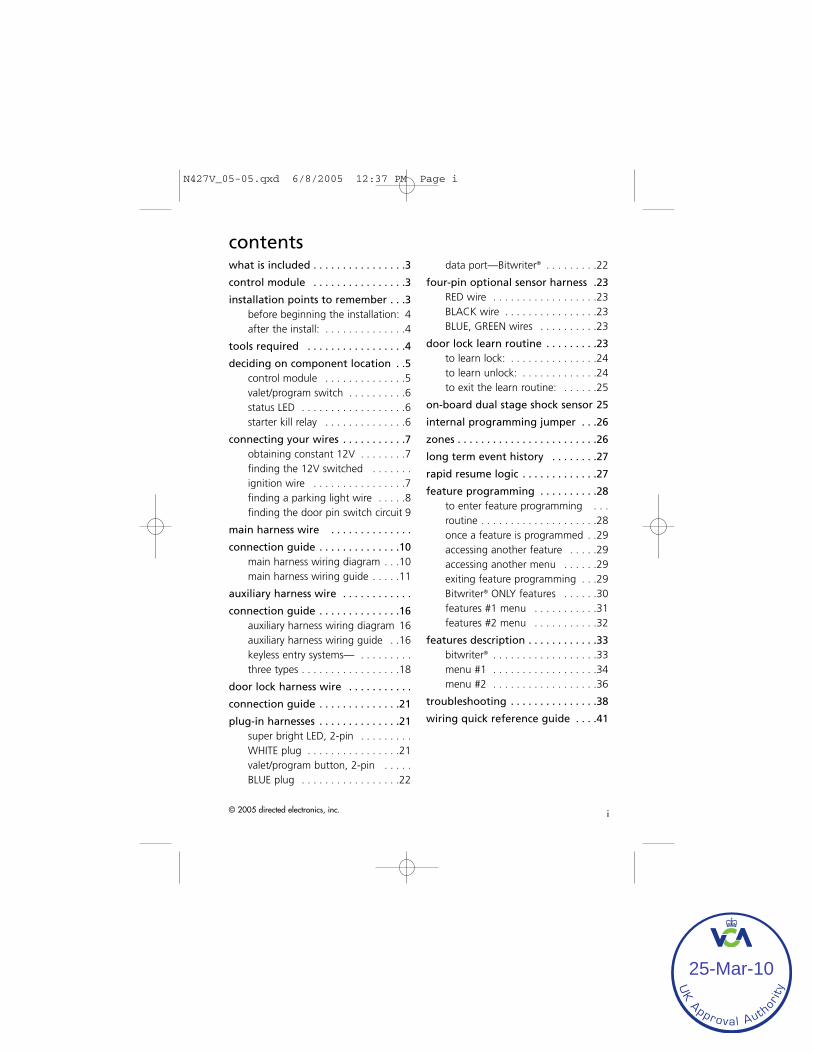
© 2005 directed electronics, inc. i
contentswhat is included . . . . . . . . . . . . . . . .3
control module . . . . . . . . . . . . . . . .3
installation points to remember . . .3before beginning the installation: 4after the install: . . . . . . . . . . . . . .4
tools required . . . . . . . . . . . . . . . . .4
deciding on component location . .5control module . . . . . . . . . . . . . .5valet/program switch . . . . . . . . . .6status LED . . . . . . . . . . . . . . . . . .6starter kill relay . . . . . . . . . . . . . .6
connecting your wires . . . . . . . . . . .7obtaining constant 12V . . . . . . . .7finding the 12V switched . . . . . . .ignition wire . . . . . . . . . . . . . . . .7finding a parking light wire . . . . .8finding the door pin switch circuit 9
main harness wire . . . . . . . . . . . . . .
connection guide . . . . . . . . . . . . . .10main harness wiring diagram . . .10main harness wiring guide . . . . .11
auxiliary harness wire . . . . . . . . . . . .
connection guide . . . . . . . . . . . . . .16auxiliary harness wiring diagram 16auxiliary harness wiring guide . .16keyless entry systems— . . . . . . . . .three types . . . . . . . . . . . . . . . . .18
door lock harness wire . . . . . . . . . . .
connection guide . . . . . . . . . . . . . .21
plug-in harnesses . . . . . . . . . . . . . .21super bright LED, 2-pin . . . . . . . . .WHITE plug . . . . . . . . . . . . . . . .21valet/program button, 2-pin . . . . .BLUE plug . . . . . . . . . . . . . . . . .22
data port—Bitwriter® . . . . . . . . .22
four-pin optional sensor harness .23RED wire . . . . . . . . . . . . . . . . . .23BLACK wire . . . . . . . . . . . . . . . .23BLUE, GREEN wires . . . . . . . . . .23
door lock learn routine . . . . . . . . .23to learn lock: . . . . . . . . . . . . . . .24to learn unlock: . . . . . . . . . . . . .24to exit the learn routine: . . . . . .25
on-board dual stage shock sensor 25
internal programming jumper . . .26
zones . . . . . . . . . . . . . . . . . . . . . . . .26
long term event history . . . . . . . .27
rapid resume logic . . . . . . . . . . . . .27
feature programming . . . . . . . . . .28to enter feature programming . . .routine . . . . . . . . . . . . . . . . . . . .28once a feature is programmed . .29accessing another feature . . . . .29accessing another menu . . . . . .29exiting feature programming . . .29Bitwriter® ONLY features . . . . . .30features #1 menu . . . . . . . . . . .31features #2 menu . . . . . . . . . . .32
features description . . . . . . . . . . . .33bitwriter® . . . . . . . . . . . . . . . . . .33menu #1 . . . . . . . . . . . . . . . . . .34menu #2 . . . . . . . . . . . . . . . . . .36
troubleshooting . . . . . . . . . . . . . . .38
wiring quick reference guide . . . .41
N427V_05-05.qxd 6/8/2005 12:37 PM Page i
UK Approval Auth
orit
y
25-Mar-10

ii © 2005 directed electronics, inc.
N427V_05-05.qxd 6/8/2005 12:37 PM Page ii
UK Approval Auth
orit
y
25-Mar-10

© 2005 directed electronics, inc. 3
what is includedControl module 4-pin sensor harness
12-pin main harness Valet switch
7-pin door monitor/Aux harness LED
Siren 3-pin door lock harness
Dual-diode light flash adapter Door lock pulse adapter
control module
installation points to rememberThis product represents many years of research and development. It is very sophisti-cated and should be installed by experienced security installers only. Please do notattempt installation of this product without reading this guide. The system has been de-signed to provide the ultimate in security, coupled with limitless convenience and ex-pansion options.
This product is not intended for consumer installation and will have NO WARRANTYunless it is installed by an authorized dealer.
BITWRITER®
DEALERMASTER
CONTROLLOOP
OPTIONALRECEIVER
(NOT USED)
SHOCK SENSORADJUSTMENT
12-PINMAIN
HARNESS
VALET®(INTEGRATED
LED/VALETSWITCH)
OPTIONALSENSOR
INPUT(506T OR 504D)
7-PIN DOOR MONITOR/AUX HARNESS
DOOR LOCK
LED (INTEGRATED LED/VALET® SWITCH)
10-AMPFUSE/JUMPER
ACCESS
N427V_05-05.qxd 6/8/2005 12:37 PM Page 3
UK Approval Auth
orit
y
25-Mar-10

4 © 2005 directed electronics, inc.
Do not disconnect the battery if the vehicle has an anti-theft coded radio. If equippedwith an airbag, avoid disconnecting the battery if possible.
IIMMPPOORRTTAANNTT!! Please read this entire installation guide before beginning the installa-tion. The installation of this security system requires interfacing with many of the vehi-cle’s systems. Many new vehicles use low-voltage or multiplexed systems which canbe damaged by low resistance testing devices, such as test lights or logic probes. Testall circuits with a high-quality digital multi-meter before making the connections.
IMMPPOORRTTAANNTT!! Many airbag systems will display a diagnostic code through their warn-ing light after they lose power. Disconnecting the battery requires this code to beerased, a procedure that can require a trip to the dealer.
before beginning the installation:
Check with the customer to determine the LED and Valet switch locations.
Remove the domelight fuse. This prevents accidentally draining the battery.
Roll down a window to avoid being locked out of the car.
after the install:
Test all functions. The “Using Your System” section of the Owner’s Guide is veryhelpful when testing.
When testing, don’t forget that this system is equipped with Nuisance Prevention® Circuitry.NPC™ can bypass both sensor zones, making them seem to stop working.
Carefully reassemble the under-dash trim panels.
Inspect the engine compartment for tools that may have been left behind.
tools requiredThis is a general list of tools required to complete the installation of this security sys-tem in most vehicles. Some vehicles may require additional tools.
Digital multi-meter Nutdriver and/or socket set
Wire cutters/strippers Panel removal tool
N427V_05-05.qxd 6/8/2005 12:37 PM Page 4
UK Approval Auth
orit
y
25-Mar-10

© 2005 directed electronics, inc. 5
Solderless terminal crimpers Drill bit set
Cordless power drill Phillips head screwdriver
Torx driver set Work light
deciding on component location
control module
Never put the control module in the engine compartment!
The first step in hot-wiring a vehicle is removing the driver's side underdash panel toaccess the starter and ignition wires. If the control module is placed just behind thedriver's side dash it can easily be disconnected.
When locating the control module, try to find a secure location that will not requireyou to extend the harnesses’ wires (they are 1.5 meters long). Keep it away from theheater core (or any other heat sources) and any obvious leaks.
Some good control module locations: Above the glove box, inside the center console,above the underdash fuse box, above the radio, etc.
N427V_05-05.qxd 6/8/2005 12:37 PM Page 5
UK Approval Auth
orit
y
25-Mar-10

6 © 2005 directed electronics, inc.
valet/program switch
Ensure that the location you pick for the switch has sufficient clearance to the rear. The switch shouldbe well hidden. It should be placed so passengersor stored items (such as in a glove box or centerconsole) cannot accidentally hit it. The switch fits ina 9/32" hole.
IIMMPPOORRTTAANNTT!! When the vehicle is delivered, please show the user where the switchis located and how to disarm the system with it.
status LED
Things to remember when positioning the Status LED:
• It should be visible from both sides and therear of the vehicle, if possible.
• It needs at least 1/2" clearance to the rear.
• It is easiest to use a small removable panel,such as a switch blank or a dash bezel.Remove it before drilling your 9/32" hole.
• Use quick-disconnects near the LED wires ifthe panel is removable. This allows mechan-ics or other installers to remove the panelwithout cutting the wires.
starter kill relay
If the Starter Kill Relay or it’s connections are immediately visible upon removal of theunderdash panel, they can easily be bypassed. Always make the relay and its con-nections difficult to discern from the factory wiring! Exposed yellow butt connectors donot look like factory parts, and will not fool anyone! For this reason, routing the starterkill wires away from the steering column is recommended.
N427V_05-05.qxd 6/8/2005 12:37 PM Page 6
UK Approval Auth
orit
y
25-Mar-10

© 2005 directed electronics, inc. 7
connecting your wiresNow that you have decided where each component will be located, you’re going tofind the wires in the car that the security system will be connected to.
IIMMPPOORRTTAANNTT!! Do not use a 12V test light to find these wires! All testing described inthis manual is described using a digital multimeter.
obtaining constant 12V
We recommend two possible sources for 12V constant: The (+) terminal of the battery,or the constant supply to the ignition switch. AAllwwaayyss iinnssttaallll aa ffuussee wwiitthhiinn 1122 iinncchheess oofftthhiiss ccoonnnneeccttiioonn..
IIMMPPOORRTTAANNTT!! Do not remove the fuse holder on the red (H1/11) wire. It ensures thatthe control module has it’s own fuse, of the proper value, regardless of how manyaccessories are added to the main power feed.
finding the 12V switched ignition wire
The ignition wire is powered when the key is in the run or start position. This isbecause the ignition wire powers the ignition system (spark plugs, coil) as well as thefuel delivery system (fuel pump, fuel injection computer). Accessory wires, on the otherhand, lose power when the key is in the start position to make more current availableto the starter motor. Use the following procedure to find (+)12V with your multimeter.
N427V_05-05.qxd 6/8/2005 12:37 PM Page 7
UK Approval Auth
orit
y
25-Mar-10

8 © 2005 directed electronics, inc.
1. Set to DCV or DC voltage (12V or 20V is fine).
2. Attach the (-) probe of the meter to chassis ground.
3. Probe the wire you suspect of being the ignition wire.The steering column harness or ignition switch harness isan excellent place to find this wire.
4. Turn the ignition key switch to the run position. If yourmeter reads (+)12V, go to the next step. If it doesn’t, probeanother wire.
5. Now turn the key to the start position. The meter dis-play should stay steady, not dropping by more than a fewtenths of a volt. If it drops close to or all the way to zero,go back to step 3. If it stays steady at (+)12V, you havefound an ignition wire.
finding a parking light wire
The parking light wire is often found near the switch. Many cars have the switch builtinto the turn signal lever, and in these cars the parking light wire can be found in thesteering column. The same wire is often available in the kick panel or running board.
(+) parking light wire
Use the following procedure to find (+) parking light wire with your multimeter.
1. Set to DCV or DC voltage (12V or 20V is fine).
2. Attach the (-) probe of the meter tochassis ground.
3. Probe the wire you suspect of being theparking light wire. Usually, the areanear the headlight/parking light switchis an excellent area to start, as is thekick panel.
4. Turn on the parking lights. If your meter shows (+)12V, turn off the parking lightsand make sure it goes back to zero.
5. If it does return to zero, turn the parking lights back on and, using the dash lightdimmer control, turn the brightness of the dash lights up and down. If the meter
N427V_05-05.qxd 6/8/2005 12:37 PM Page 8
UK Approval Auth
orit
y
25-Mar-10

© 2005 directed electronics, inc. 9
changes more than a volt when using the dimmer, look for another wire. If itstays relatively close to (+)12V, you have found your parking light wire.
(-) parking light wire
Use the following procedure to find (-) parking light wire with your multimeter.
1. Set to DCV or DC voltage (12V or 20V is fine).
2. Attach the (+) probe of the meter to+12V.
3. Probe the wire you suspect of being theparking light wire. Usually, the areanear the headlight/parking light switchis an excellent area to start, as is thekick panel.
4. Turn on the parking lights. If your meter shows (+)12V, turn off the parking lightsand make sure it goes back to zero.
5. If it does return to zero, turn the parking lights back on and, using the dash lightdimmer control, turn the brightness of the dash lights up and down. If the meterchanges more than a volt when using the dimmer, look for another wire. If itstays relatively close to (+)12V, you have found your parking light wire.
finding the door pin switch circuit
The best places to find the door switch wire are:
At the pin switch: When testing at the pin switch, check the wire to ensure that it “sees”all the doors. Often, the passenger switch will cover all the doors even if the driver’sswitch will not.
At the dome light: This may not be your best choice if the vehicle has delayed domelightsupervision, but it will work in vehicles with completely diode-isolated pin switches.
Often the door switch wires, described above, can also be found in the windshield pil-lars, running boards or kick plates.
Use the following procedure to find the door pin switch wire with your multimeter.
1. Set to DCV or DC voltage (12V or 20V is fine).
N427V_05-05.qxd 6/8/2005 12:37 PM Page 9
UK Approval Auth
orit
y
25-Mar-10

10 © 2005 directed electronics, inc.
2. In most cars, fasten the (+) probe of your meter to (+)12V constant.
3. Probe the wire you suspect of being the door trigger wire. If the meter reads(+)12V when any door is opened and the meter goes to 0 with the door closed,you have found a trigger wire.
NNOOTTEE: Make sure the wire you use “sees” all the doors! Some newer vehicles lackstandard-type pinswitches. The dome light in these vehicles is turned on when the doorhandle is lifted. These usually have a wire coming out of the door into the kick panelwhich will provide a (-) trigger for all doors.
main harness wire connection guide
main harness wiring diagram
___
___
___
___
___
___
___
___
___
___
___
___ RED/WHITE (-) 200mA Auxiliary Channel/Delayed Accessory Output
RED (+) 12V Constant Power Input
BROWN (+) Siren Output
YELLOW (+) Ignition Input
BLACK (-) Chassis Ground Input
VIOLET (+) Door Trigger Input
BLUE (-) Instant Trigger (Hood and Trunk Pin)
GREEN (-) Door Trigger Input
BLACK/WHITE (-) 200mA Domelight Supervision Output
WHITE/BLUE No Function
WHITE (+)/(-) Light Flash Output
ORANGE (-) 500mA Ground When Armed H1/1
H1/2
H1/3
H1/4
H1/5
H1/6
H1/7
H1/8
H1/9
H1/10
H1/11
H1/12
N427V_05-05.qxd 6/8/2005 12:37 PM Page 10
UK Approval Auth
orit
y
25-Mar-10

© 2005 directed electronics, inc. 11
main harness wiring guide
HH11//11 OORRAANNGGEE ((--)) 550000 mmAA ggrroouunndd--wwhheenn--aarrmmeedd oouuttppuutt:: This wire supplies a (-)ground as long as the system is armed. This output ceases as soon as the system isdisarmed. This wire controls operation of the pre-wired starter kill relay and can beused to control other optional accessories.
NNOOTTEE:: If connecting the orange wire to control another module, such as a 529T or530T window controller, a 1 amp diode (type 1N4004) will be required. Insert thediode as shown below.
IIMMPPOORRTTAANNTT!! Never interrupt any wire other than the starter wire.
HH11//22 WWHHIITTEE lliigghhtt ffllaasshh oouuttppuutt:: As shipped, this wire should be connected to the (+)parking light wire. It will supply a (+) 10A output. If the light flash polarity fuse jumperinside the unit is moved to the opposite position (see Internal Jumpers), this wire sup-plies a (-) 10A output. This is suitable for driving (-)parking light wires.
NNOOTTEE:: A dual diode harness assembly is provided (Viper model only) for Europeanvehicles which have parking light capability for illumination of only the parking lightson the side of the vehicle to the road when parked.
N427V_05-05.qxd 6/8/2005 12:37 PM Page 11
UK Approval Auth
orit
y
25-Mar-10

12 © 2005 directed electronics, inc.
HH11//33 WWHHIITTEE//BBLLUUEE nnoo ffuunnccttiioonn..
HH11//44 BBLLAACCKK//WWHHIITTEE ((--)) 220000 mmAA ddoommeelliigghhtt--ssuuppeerrvviissiioonn oouuttppuutt:: Connect this wire tothe optional domelight supervision relay.
IIMMPPOORRTTAANNTT!! This output is only intended to drive a relay. It cannot be connecteddirectly to the domelight circuit, as the output cannot support the current draw of oneor more bulbs.
LIGHT BULB
PARKING LIGHTRELAY OR SWITCH
(+) 12V WHITE H1/2(-) LIGHT FLASH OUTPUT
N427V_05-05.qxd 6/8/2005 12:37 PM Page 12
UK Approval Auth
orit
y
25-Mar-10

© 2005 directed electronics, inc. 13
HH11//55 GGRREEEENN ((--)) ddoooorr ttrriiggggeerr iinnppuutt: Most vehicles use negative door trigger circuits.Connect the green wire to a wire which shows ground when any door is opened. Invehicles with factory delays on the domelight circuit, there is usually a wire that isunaffected by the delay circuitry.
HH11//66 BBLLUUEE ((--)) iinnssttaanntt ttrriiggggeerr:: This input will respond to a negative input with aninstant trigger. It is ideal for hood and trunk pins and will report on zone one.
HH11//77 VVIIOOLLEETT ((++)) ddoooorr ttrriiggggeerr iinnppuutt:: This wire is used in vehicles that have a positive(+) switched dome light circuit . Connect the violet wire to a wire that shows (+)12Vwhen any door is opened, and ground when the door is closed.
N427V_05-05.qxd 6/8/2005 12:37 PM Page 13
UK Approval Auth
orit
y
25-Mar-10

14 © 2005 directed electronics, inc.
HH11//88 BBLLAACCKK ((--)) cchhaassssiiss ggrroouunndd ccoonnnneeccttiioonn:: Connect this wire to bare metal,preferably with a factory bolt rather than your own screw. Screws tend to eitherstrip or loosen with time. All components, should be grounded to the same pointin the vehicle if possible.
HH11//99 YYEELLLLOOWW ((++)) iiggnniittiioonn iinnppuutt:: Connect this wire to the (+)12V ignition wire. Thiswire must show (+)12V with the key in Run position and during cranking. Take careto insure that this wire cannot be shorted to the vehicle chassis at any point.
N427V_05-05.qxd 6/8/2005 12:37 PM Page 14
UK Approval Auth
orit
y
25-Mar-10
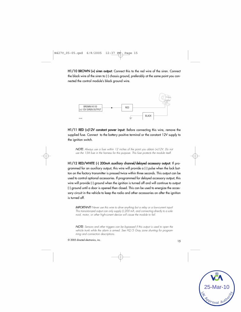
© 2005 directed electronics, inc. 15
HH11//1100 BBRROOWWNN ((++)) ssiirreenn oouuttppuutt:: Connect this to the red wire of the siren. Connectthe black wire of the siren to (-) chassis ground, preferably at the same point you con-nected the control module’s black ground wire.
HH11//1111 RREEDD ((++))1122VV ccoonnssttaanntt ppoowweerr iinnppuutt:: Before connecting this wire, remove thesupplied fuse. Connect to the battery positive terminal or the constant 12V supply tothe ignition switch.
NNOOTTEE:: Always use a fuse within 12 inches of the point you obtain (+)12V. Do notuse the 15A fuse in the harness for this purpose. This fuse protects the module itself.
HH11//1122 RREEDD//WWHHIITTEE ((--)) 220000mmAA aauuxxiilliiaarryy cchhaannnneell//ddeellaayyeedd aacccceessssoorryy oouuttppuutt:: If pro-grammed for an auxiliary output, this wire will provide a (-) pulse when the lock but-ton on the factory transmitter is pressed twice within three seconds. This output can beused to control optional accessories. If programmed for delayed accessory output, thiswire will provide (-) ground when the ignition is turned off and will continue to output(-) ground until a door is opened then closed. This can be used to energize the acces-sory circuit in the vehicle to keep the radio and other accessories on after the ignitionis turned off.
IIMMPPOORRTTAANNTT!! Never use this wire to drive anything but a relay or a low-current input!This transistorized output can only supply (-) 200 mA, and connecting directly to a sole-noid, motor, or other high-current device will cause the module to fail.
NNOOTTEE:: Sensors and other triggers can be bypassed if this output is used to open thevehicle trunk while the alarm is armed. See H2/5 Gray zone shunting for program-ming and connection descriptions.
N427V_05-05.qxd 6/8/2005 12:37 PM Page 15
UK Approval Auth
orit
y
25-Mar-10

16 © 2005 directed electronics, inc.
auxiliary harness wire connection guide
auxiliary harness wiring diagram
___
___
___
___
___
___
___
auxiliary harness wiring guide
HH22//11 BBRROOWWNN ((--)) hhoorrnn hhoonnkk oouuttppuutt:: This wire supplies a 200 mA (-) output that canbe used to honk the vehicle’s horn. It provides a pulsed output when the security sys-tem is armed/disarmed and in the triggered sequence or in panic mode. In most vehi-cle’s with (-) horn circuits this wire can control the vehicle’s horn without adding arelay. If the vehicle has a (+) horn circuit, an optional relay must be used to interfacewith the vehicle’s horn circuit.
IIMMPPOORRTTAANNTT!! Never use this wire to drive anything but a relay or a low-current input!This transistorized output can only supply (-) 200 mA, and connecting directly to a sole-noid, motor, or other high-current device will cause the module to fail.
HH22//22 GGRREEEENN ffoorr aarrmm iinnppuutt:: Connect this GREEN wire to a wire that changes state whenthe doors are locked using the factory keyless entry transmitter. This wire can accept apositive (+) or negative (-) input. The vehicle’s power door lock motor wire is ideal.
HH22//33 RREEDD ddiissaarrmm ddeeffeeaatt iinnppuutt:: This wire is used to prevent the interior door lockswitches from disarming the system. To determine the best location to interface thiswire, first test the operation of the remote keyless entry system. When unlocking thedoors with the factory remote transmitter, does the driver’s door unlock first? Most
YELLOW/BLACK Light Flash Monitor Input
VIOLET/BLACK No Function
GRAY (+) Trunk Release/Sensor Shunt Input
BLUE Disarm Input
RED Disarm Defeat Input
GREEN Arm Input
BROWN (-) Horn Honk OutputH2/1
H2/2
H2/3
H2/4
H2/5
H2/6
H2/7
N427V_05-05.qxd 6/8/2005 12:37 PM Page 16
UK Approval Auth
orit
y
25-Mar-10

© 2005 directed electronics, inc. 17
vehicles operate this way. If this is the case connect the RED wire to the passengerunlock motor wire. When testing this wire be sure that it shows 12V (+) ONLY whenthe unlock button on the factory transmitter is pressed the second time to unlock thepassenger doors. If the factory keyless entry system unlocks all of the doors at thesame time, it is recommended that the H2/7 YELLOW/BLACK wire be used for dis-arm defeat input.
NNOOTTEE:: The H2/3 wire connection is not required if using H2/7 YELLOW/BLACK as adisarm defeat wire.
HH22//44 BBLLUUEE ddiissaarrmm iinnppuutt:: Connect the BLUE wire to a wire that changes state when thedoors are unlocked using the factory keyless entry transmitter. If the factory transmitterunlocks the driver’s door first, the BLUE wire must be connected to the wire that changesstate when the driver’s door is unlocked by itself. In this case, find the driver’s doorunlock motor wire. In most vehicle’s this wire can be found in the driver’s kick panel.
NNOOTTEE:: Some vehicles (some of the Honda, GM and Ford) have long door lock puls-es. These long pulses may interfere with the disarm function of this system when unlock-ing all doors using the factory OEM remote. Use the supplied door unlock pulseadapter for these vehicles. Refer to the diagram below.
HH22//55 GGRRAAYY ttrruunnkk rreelleeaassee//sseennssoorr sshhuunntt iinnppuutt:: This input is used to bypass the sensorinputs when the trunk is opened using the factory keyless entry system or trunk releaserelay while armed. When the system receives a (+) input on this wire, zones 1, 2 and4 are bypassed for 3-seconds. If during that 3-seconds, ground is applied to the H1/6
CONTROL MODULE
+ -
0.47 mFPOLARIZED
CAP 25V OR
HIGHER
UNLOCK MOTORWIRE
DIODE
6.2 MΩRESISTOR(BLUE-RED-GREEN-SILVER OR GOLD)
BLUE - DISARM WIRE
BLACK/WHITE
WHITE/BLUEBLUE/WHITE
DOOR UNLOCKPULSE ADAPTER
N427V_05-05.qxd 6/8/2005 12:37 PM Page 17
UK Approval Auth
orit
y
25-Mar-10

18 © 2005 directed electronics, inc.
BLUE wire then the alarm zones are bypassed (See Feature menu 1/8) and willremain bypassed until the ground input is removed. This means that when the trunk isopen with the factory transmitter the only triggers that remain active while the trunk isopen are the doors and ignition. 3-seconds after the trunk is closed the bypassedzones again become active.
HH22//66 VVIIOOLLEETT//BBLLAACCKK nnoo ffuunnccttiioonn..
HH22//77 YYEELLLLOOWW//BBLLAACCKK lliigghhtt ffllaasshh mmoonniittoorr iinnppuutt:: This input monitors the factory sys-tem light flash output and can be used as a disarm defeat wire. Connect this wire tothe light flash wire that flashes when the factory transmitter is used. This may be a sta-tus LED, parking lights, reverse lights, etc., depending on the vehicle type and manu-facturer. This wire can accept a (+) positive or (-) negative input.
keyless entry systems—three types
There are three main types of keyless entry systems. Systems that unlock the driver’sdoor first and have internal relays, systems that unlock the driver’s door first but haveexternal relays, and systems without driver’s priority door unlock.
factory remote—driver’s door unlock
N427V_05-05.qxd 6/8/2005 12:37 PM Page 18
UK Approval Auth
orit
y
25-Mar-10

© 2005 directed electronics, inc. 19
external relays—driver’s door unlock
This system is used in many four-door GM sedans. To test for this type of system, probethe unlock wire from the interior switch (black or white). Unlock the driver’s door, byitself, using the factory remote. If the switch wire shows (+) 12V, then use the follow-ing diagram:
NNOOTTEE:: It is often easy to access the passenger unlock wire going to the rear doormotor on the driver’s side.
N427V_05-05.qxd 6/8/2005 12:37 PM Page 19
UK Approval Auth
orit
y
25-Mar-10

20 © 2005 directed electronics, inc.
no priority—driver’s door unlock
This type of keyless entry system is common in import vehicles as well as many Jeepvehicles. When unlocking the doors with the transmitter all doors unlock at the sametime. It is recommended to use H2/7 YELLOW/BLACK wire for Disarm Defeat insteadof the H2/3 RED wire. This input wire monitors the factory system light flash output.Connect this wire to the light flash wire that flashes when the factory transmitter isused. This may be a status LED, parking lights, reverse lights, etc., depending on thevehicle type and manufacturer. Do NOT connect this wire to the domelight. This wirecan accept a (+) positive or (-) negative input.
For installation, please refer to the diagram below.
H2/7 YEL/BLK
(NOT USED)
PARKING LIGHT RELAYOR SWITCH
PARKING LIGHT BULB
N427V_05-05.qxd 6/8/2005 12:37 PM Page 20
UK Approval Auth
orit
y
25-Mar-10

© 2005 directed electronics, inc. 21
door lock harness wire connection guide
These door lock outputs are for Passive arming control of the factory door locks.They can also be used to control the door locks with the ignition switch for vehiclethat do not have this feature in the factory RKE system.
___
___
___
The control module can control 2 common power door lock types without any addition-al parts. With certain vehicles, or if an actuator is to be installed, either a 451M DoorLock Relay Satellite or two relays will be required. Refer to TechTips document 1041.
plug-in harnesses
super bright LED, 2-pin WHITE plug
The super bright LED operates at (+) 2 volt DC and plugs into the two-pin WHITE port.Make sure the LED wires are not shorted to ground as the LED will be damaged.Multiple LED’s can be used, but they must be wired in series. The LED fits into a 9/32-inch mounting hole. Be sure to check for clearance prior to drilling the mounting hole.
NNOOTTEE:: Never use a BLUE LED in combination with a RED LED.
������
BLUE (-) Unlock, (+) Lock Output
Not Used
GREEN (-) Lock, (+) Unlock OutputH3/A
H3/B
H3/C
N427V_05-05.qxd 6/8/2005 12:37 PM Page 21
UK Approval Auth
orit
y
25-Mar-10

22 © 2005 directed electronics, inc.
valet/program button, 2-pin BLUE plug
The Valet/Program button should be accessible from the driver’s seat. It plugs into theBLUE port on the side of the unit. Since the system features Valet® by using the remotetransmitter, the button can be well hidden. Consider how the button will be usedbefore choosing a mounting location. Check for rear clearance before drilling a9/32-inch hole and mounting the button.The GRAY wire in the two-pin plug may alsobe used as a (+) ghost switch input and can be connected to any (+) switch in the vehi-cle. (See Feature Descriptions section of this guide.)
data port—Bitwriter®
The black three-pin port can be used for programming the unit using the DirectedBitwriter, a hand held programming tool. The Bitwriter also allows programming offeatures that are not available in the feature menus.
N427V_05-05.qxd 6/8/2005 12:37 PM Page 22
UK Approval Auth
orit
y
25-Mar-10

© 2005 directed electronics, inc. 23
four-pin optional sensor harness
RED wire
The red wire supplies constant power to the optional sensor.
BLACK wire
The black wire supplies ground to the optional sensor.
BLUE, GREEN wires
The blue and green wires are multiplex inputs. They are both tied to the same zone.If an input of less than 0.8 seconds is supplied to either wire the Warn-Away®
response will occur. An input longer than 0.8 seconds to either wire will initiate thetriggered sequence and report zone 4. This port can be used for optional sensors suchas: the 506T—glass breakage sensor, or the 504D—field disturbance sensor.
door lock learn routineBefore the unit will respond to the factory remote keyless system, it must learn thepolarity of the door lock wires. To learn the lock polarity:
NNOOTTEE:: It is important that all the INPUT signals to the control module are in the rest sta-tus state (no activity) before entering the learn routine.
N427V_05-05.qxd 6/8/2005 12:37 PM Page 23
UK Approval Auth
orit
y
25-Mar-10

24 © 2005 directed electronics, inc.
to learn lock:
NNOOTTEE:: Make sure the doors, hood and trunk are closed so the factory RKE system oper-ates as it would when the user is using it.
11.. WWiitthh aallll tthhee ddoooorrss,, hhoooodd aanndd ttrruunnkk cclloosseedd:: Press and HOLD the Valet® button.
22.. WWiitthhiinn 55--sseeccoonnddss:: Turn the ignition On and then Off (leave for less than 2-secondsin the on position).
33.. WWiitthhiinn 55--sseeccoonnddss:: Release the Valet® button.
44.. WWiitthhiinn 55--sseeccoonnddss:: Press and release the Valet® button once.
55.. WWiitthhiinn 55--sseeccoonnddss:: Press and HOLD the Valet® button. The LED will flash to indicatethat the lock routine is ready to be learned.
66.. PPrreessss lloocckk bbuuttttoonn:: Press the lock button on the factory transmitter. Wait for the LEDto illuminate to indicate the the lock learn was successful. If the learn was unsuccess-ful the LED would continue to flash.
77.. RReelleeaassee tthhee VVaalleett®® bbuuttttoonn.. Now advance to the learn Unlock routine.
to learn unlock:
11.. WWiitthhiinn 55--sseeccoonnddss of the learn lock routine (step 7), press and release the Valet® but-ton once.
22.. WWiitthhiinn 55--sseeccoonnddss:: Press and HOLD the Valet® button. The LED will flash in groupsof two flashes to indicate that the unlock routine is ready to be learned.
33.. PPrreessss uunnlloocckk bbuuttttoonn:: Press the unlock button on the factory transmitter. The LED willilluminate for a maximum of 5-seconds to indicate that the unlock learn was success-ful. If the learn was unsuccessful the LED would continue to flash in groups of two.
44.. RReelleeaassee tthhee VVaalleett®® bbuuttttoonn..
N427V_05-05.qxd 6/8/2005 12:37 PM Page 24
UK Approval Auth
orit
y
25-Mar-10

© 2005 directed electronics, inc. 25
NNOOTTEE:: If the Unlock learn was unsuccessful, the Unlock procedure can be repeatedby using the LOCK learn procedure, except that at step 4 press and release the Valet®
button TWICE. (The LED will flash in groups of two flashes.)
to exit the learn routine:
Do one of the following:
Turn the ignition on.
No activity for longer than 15 seconds.
Press the Valet® button too many times.
on-board dual stage shock sensor
There is a dual-stage shock sensor inside the control module. Adjustments are made viathe rotary control as indicated above. Since the shock sensor does not work well whenmounted firmly to metal, we recommend against screwing down the control module. Thefull trigger of the onboard shock sensor reports zone 2. See Table of Zones.
NNOOTTEE:: When adjusting the sensor, it must be in the same mounting location that it willbe after the install is completed. Adjusting the sensor and then relocating the modulerequires readjustment.
Less Sensitive More Sensitive
N427V_05-05.qxd 6/8/2005 12:37 PM Page 25
UK Approval Auth
orit
y
25-Mar-10

26 © 2005 directed electronics, inc.
internal programming jumperA 10A fuse is used as both a fuse and a program jumper. This jumper determines thelight flash output polarity. In the (+) position, the on-board relay is enabled and theunit will output (+)12V on the WHITE wire, H1/2. In the (-) position, the on-boardrelay is enabled for (-) output on the WHITE wire, H1/2. To access the jumper, removethe sliding door from on top of the control module, as shown below.
zones
NNOOTTEE:: The Warn Away® response does not report on the LED.
ZoneNumber Trigger Type Input Description
1 Instant trigger Hood and/or trunk pin switches.
2 Multiplexed input Heavy impact from on-boardDoublegurard® shock sensor.
3 Two-stage, progresses from warningto full alarm
Door switch circuit.
4 Multiplexed Optional sensor, Inputs shorter than0.8 seconds will trigger Warn Away®
response, while inputs longer than0.8 seconds will instantly trigger fullalarm.
5 Two-stage (similar to zone 3) Ignition input.
FUSE/JUMPER(-) POSITION
FUSE/JUMPER(+) POSITION
N427V_05-05.qxd 6/8/2005 12:37 PM Page 26
UK Approval Auth
orit
y
25-Mar-10

© 2005 directed electronics, inc. 27
long term event historyThe control module will store the last 2 triggers in memory that are not erased whenthe ignition is turned on. This can be helpful for trouble shooting false alarm reports.To access the event history use the following procedure.
1. Turn the ignition switch off and press and hold the Valet® button.
2. While holding the Valet® button turn the ignition On.
3. Release the Valet® button.
4. Within 5-seconds, press and release the Valet® button.
The LED will flash in groups indicating the last two zones reported triggered. Forexample, if zone 2 and 3 were the last two zones to be triggered, the LED will flashtwo times followed by a pause and then flash three times followed by a pause.
NNOOTTEE:: The Warn Away® response does not report on the LED.
The Long Term Event History will exit if the ignition is turned off or there is no activityfor 60-seconds.
rapid resume logicThe current state of the alarm will be stored in non-volatile memory. If power is lostand then reconnected, the system will recall the stored state from memory (arm, dis-arm, and Valet® mode).
N427V_05-05.qxd 6/8/2005 12:37 PM Page 27
UK Approval Auth
orit
y
25-Mar-10

28 © 2005 directed electronics, inc.
feature programmingThe feature programming routine is used to access and change any of the feature set-tings in the two menus below. The feature settings can be accessed and changed byusing one of the following:
The Valet® button to enter the feature programming routine.
Use of the Directed Electronics Bitwriter® is recommended. Expanded program-ming options are only available when using the Directed Electronics Bitwriter®.
NNOOTTEE:: If Feature Programming Lockout is set to ON, all features will be locked andcan OONNLLYY be accessed by using a Bitwriter®.
to enter feature programming routine
1. Open a door.
2. Turn the ignition on and then off.
3. Close the door.
NNOOTTEE:: If the domelight is used for the door trigger input, the dome light must be OFFbefore proceeding to the next step.
4. Within 5-seconds, press and HOLD the Valet® button. After 3-seconds the horn willsound once to indicate entry into the first features menu. To select the second featuresmenu, continue to hold the Valet® button until the horn sounds twice. Once the desiredmenu is selected, release the Valet® button.
5. Within 5-seconds, press and release the Valet® button the number of times corre-sponding to the desired feature listed below. Then press the Valet® button one moretime and hhoolldd. The horn will sound the number of times equal to the feature numberselected.
6. While holding the Valet® button, assign the selected feature to a factory button byeither pressing Lock for 1 short horn honk setting or pressing Unlock for 2 short hornhonk setting.
N427V_05-05.qxd 6/8/2005 12:37 PM Page 28
UK Approval Auth
orit
y
25-Mar-10

© 2005 directed electronics, inc. 29
once a feature is programmed
Another feature(s) can be programmed.
The other feature menu can be selected.
The Learn Routine can be exited.
accessing another feature
Release, then press and release the Valet® button the number of times to advancefrom the feature just programmed to the next feature desired.
Press and hhoolldd the Valet® button once more.
The horn will chirp to confirm the feature selected.
accessing another menu
Release, then press and release hhoolldd the Valet® button.
After 3-seconds, the unit will advance to the next menu and the horn will sound2 times to indicate feature menu 2 has been entered.
exiting feature programming
Open the door.
Turn the ignition On.
No activity for 15-seconds.
Press and release the Valet® button too many times.
N427V_05-05.qxd 6/8/2005 12:37 PM Page 29
UK Approval Auth
orit
y
25-Mar-10

30 © 2005 directed electronics, inc.
Bitwriter® ONLY features
Due to memory limitations for this system, the following features can only be pro-grammed using Directed’s Bitwriter® programmer. Factory default settings are shownin bboolldd.
B-1 Forced passive arming ON Forced passive arming OFF
B-2 NPC ON NPC OFF
B-3 Panic with ignition ON Panic with ignition OFF
B-4 Dealer security features ON Dealer security features OFF
B-5 Transmitter programming UNLOCKED Transmitter programming LOCKED
B-6 Feature programming UNLOCKED Feature programming LOCKED
B-7 Siren duration — 0 to 180 seconds programmable
N427V_05-05.qxd 6/8/2005 12:37 PM Page 30
UK Approval Auth
orit
y
25-Mar-10

© 2005 directed electronics, inc. 31
features #1 menu
Factory default settings are shown in bboolldd.
FeatureStep Lock Button (one chirp) Unlock Button (two chirps)
1-1 Active arming Passive arming
1-2 Chirps ON Chirps OFF
1-3 Door Trigger Error Chirp ON Door Trigger Error Chirp OFF
1-4 Ignition-Controlled Domelight ON Ignition-Controlled Domelight OFF
1-5 Panic Enabled (OEM upgrade) Auxiliary Output Enabled (OEM upgrade)
1-6 Auxiliary Output Delayed Accessory Output
1-7 Delayed Door Trigger Instant Door Trigger
1-8 Sensor shunt zones 1, 2 & 4 All zones
1-9 Siren Duration–30 seconds Siren Duration–60 seconds
1-10 Valet® switch input: 1-pulse Valet® switch input: 2-5 pulses
1-11Horn pulse honk duration 0.020seconds (does not affect full trig-ger pulse duration)
0.030, 0.040, 0.050 seconds
N427V_05-05.qxd 6/8/2005 12:37 PM Page 31
UK Approval Auth
orit
y
25-Mar-10

32 © 2005 directed electronics, inc.
features #2 menu
Factory default settings are shown in bboolldd.
NNOOTTEE:: Feature step number 6 and 7 are not applicable to the this model.
FeatureStep Lock Button (one chirp) Unlock Button (two chirps)
2-1 Ignition-Controlled Locking ON Ignition-Controlled Locking OFF
2-2 Ignition-Controlled UnLocking ON Ignition-Controlled Unlocking OFF
2-3 Active Locking Passive Locking
2-4 Door Lock Pulse Duration–0.8 sec. Door Lock Pulse Duration–3.5 sec.
2-5 Single Unlock Pulse Double Unlock Pulse
2-6 Channel 3: Validity Channel 3: Second Unlock
2-7 Code Hopping ON Code Hopping OFF
N427V_05-05.qxd 6/8/2005 12:37 PM Page 32
UK Approval Auth
orit
y
25-Mar-10

© 2005 directed electronics, inc. 33
features description
bitwriter®
B-1 FORCED PASSIVE ARMING ON/OFF: These settings control whether the systemarms passively in the event a door is left open accidentally by the user. Passivearming must be programmed on for this feature to work.
• Forced passive arming ON (Default): in this setting if passive arming is pro-grammed on and a zone is active (door open) after the ignition is turned off, thesystem will bypass the zone after 1 hour, then arm and monitor the rest of thesecurity zones.
• Forced passive arming OFF: in this setting the system will not passive arm ifany zone is left open after the ignition is turned off.
B-2 NUISANCE PREVENTION CIRCUITRY™ (NPC™) ON/OFF: These settings con-trol the number of times a sensor can trigger the system within a given time peri-od.
• NPC ON (Default): in this setting any sensor that triggers more than 3 timeswithin a 1 hour period will be bypassed for a minimum of 1 hour. If within that1 hour the system sees the same sensor trigger again it will not activate the sirenand will restart the 1 hour timer.
• NPC OFF: in this setting the sensors will trigger repeatedly until the system isdisarmed.
B-3 DEALER SECURITY FEATURES ON/OFF. This feature is not available on thismodel.
B-4 TRANSMITTER PROGRAMMING UNLOCKED/LOCKED: This feature is notavailable on this model.
B-5 FEATURE PROGRAMMING UNLOCKED/LOCKED:
• Unlocked (default): In this setting the features can be changed using the Valetswitch and the vehicle OEM transmitter.
• Locked: in this setting the features can not be changed using the Valet switchand the vehicle OEM Transmitter. If locked, the unit will emit 1 long chirp whentrying to enter feature programming.
B-6 SIREN DURATION The Bitwriter can adjust the siren duration setting anywherefrom 1 second to 180 seconds in length.
N427V_05-05.qxd 6/8/2005 12:37 PM Page 33
UK Approval Auth
orit
y
25-Mar-10

34 © 2005 directed electronics, inc.
menu #1
1-1 ACTIVE/PASSIVE ARMING: These settings control the systems mode of arming.
• Active arming mode (default): the system will only arm when the transmitter isused.
• Passive arming mode: the system will arm automatically 30 seconds after thelast door is closed or can be armed anytime using the transmitter.
1-2 CHIRPS ON/OFF: This setting controls the systems arming & disarming chirps.
• Chirps ON (default): the system will emit chirps when arming and disarming.
• Chirps OFF: the system will NOT emit chirps when arming and disarming.
1-3 DOOR TRIGGER ERROR CHIRP ON/OFF: These settings control the warningchirp that is generated if the system is armed with the door trigger input active,either due to an open door or factory delayed dome light circuit.
• Error chirp ON (default): The siren will emit a single chirp and bypass theactive input when arming the system.
• Error chirp OFF: The siren will NOT emit a chirp due to an active input whenarming and will bypass the active input. This setting is helpful for vehicles withfactory delayed dome lights.
A few seconds after the input stops (delay dome light off, door closed) the systemwill again monitor the door trigger input.
1-4 IGNITION-CONTROLLED DOMELIGHT ON/OFF: These settings control whetheror not the dome light illuminates when turning the ignition off.
• IGN dome light ON (default): The dome light will illuminate for 30 secondseach time the ignition is turned off
• IGN dome light OFF: The dome light will only turn on when disarming thesystem and turn off when the ignition is turned on.
1-5 PANIC/AUXILIARY OUTPUT ENABLED: These settings change the systems abili-ty to activate panic mode or the Channel 2 output.
• Panic mode enabled (Default): in this setting if the system sees the vehicle doorslock 2 times rapidly the Panic mode will be activated for the programmed sirenduration.
• Auxiliary channel output: in this setting the auxiliary channel output describedin Feature #6 will be activate as programmed.
N427V_05-05.qxd 6/8/2005 12:37 PM Page 34
UK Approval Auth
orit
y
25-Mar-10

© 2005 directed electronics, inc. 35
1-6 AUXILIARY/DELAYED ACCESSORY OUTPUT: These settings change Red/whiteauxiliary output operation.
• Auxiliary output (default): in this setting if the system sees the vehicle doors lock2 times rapidly the red/wht auxiliary channel will activate for 800mS. This isuseful for adding trunk release option.
• Delay accessory output: In this setting the red/wht auxiliary channel will turnon a few seconds after the ignition is turned on and remain on until a door isopened/closed, the system is armed or 1 hour lapses.
1-7 DELAYED/INSTANT DOOR TRIGGER: These setting control the siren outputwhen the system is set off by the door trigger input.
• Delay ON (default) in this setting if the door is opened while the system isarmed the siren will chirp 10 times prior to the constant siren output. This is stillan instant trigger and closing the door quickly will not stop the trigger sequence.
• Delay Off: in this setting if the door is opened while the system is armed thesiren will emit a constant siren output immediately
1-8 SENSOR SHUNT ZONES 1, 2 AND 4/ALL ZONES: These settings define whichzones are bypassed when opening the trunk while the system is armed.
• Sensor zones 1, 2 & 4 (default): in this setting zones 1, 2 & 4 are shuntedwhen the H2/5 gray wire sees a +12V input moments before H1/6 blue sees aground input.
• All zones: in this setting ALL zones are shunted when the H2/5 gray wire seesa +12V input moments before H1/6 blue sees a ground input. ALL zones will bebypassed until 5 seconds after the ground ceases on the blue wire.
1-9 SIREN DURATION 30/60 SECONDS: These settings change the siren outputfrom 30 seconds to 60 seconds duration when in the panic mode and when thesystem is fully triggered. The siren duration can also be programmed from 1-180seconds in 1 second increments using the Bitwriter®.
1-10 VALET® PULSE COUNT 1-5 PULSES: These settings change the number of timesthe valet switch must be pressed to disarm the system without a transmitter.
• 1 pulse (default): setting is 1 pulse.
• 2-5 pulses: these settings will make it more difficult for a thief to defeat thesystem.
N427V_05-05.qxd 6/8/2005 12:37 PM Page 35
UK Approval Auth
orit
y
25-Mar-10

36 © 2005 directed electronics, inc.
1-11 HORN PULSE HONK DURATION: These settings adjust the pulse length of theoptional horn honk output and allow for connection to more and less efficientvehicle horns without annoyingly loud arm/disarm honks.
• 20mS (default): for more efficient vehicle horns
• 30/40/50mS: for less efficient vehicle horns
menu #2
2-1 IGNITION-CONTROLLED LOCKING ON/OFF: This settings control whether thedoors lock automatically after ignition is turned on.
• Lock ON (default): in this setting the doors will lock automatically 3 secondsafter the ignition is turned on.
NNOOTTEE:: This output is bypassed if a door is opened at the time the ignition is turnedon.
• Lock Off: The doors will not lock automatically when the ignition is turned on.
2-2 IGNITION-CONTROLLED UNLOCKING ON/OFF: This settings control whetherthe doors unlock automatically when ignition is turned off.
• Unlock ON (default): in this setting the doors will unlock automatically whenthe ignition is turned off.
• Unlock OFF: The doors will not unlock automatically when the ignition is turnedoff.
2-3 ACTIVE/PASSIVE LOCKING: These settings control whether the doors lock whenthe system arms passively. Passive arming must be programmed on for this fea-ture to work.
• Passive locking OFF (default): in this setting the doors will not lock when thesystem arms passively. They will only lock when the transmitter is used to arm thesystem.
• Passive locking ON: in this setting the doors WILL lock when the system armspassively. The doors can also be locked when using the transmitter to arm thesystem.
NNOOTTEE:: Remember, when passive arming is selected, the unit will chirp 20 secondsafter the last door is closed. The system does not actually arm or lock the doors until30 seconds after the door has been closed.
N427V_05-05.qxd 6/8/2005 12:37 PM Page 36
UK Approval Auth
orit
y
25-Mar-10

© 2005 directed electronics, inc. 37
2-4 DOOR LOCK PULSE DURATION: These settings control the pulse length of thedoor lock output.
• 0.8seconds (Default): in this setting the output length is 800mS and can con-trol the majority of vehicle door lock systems.
• 3.5 seconds: in this setting the output length is 3.5 seconds and is usually usedin European vehicles with vacuum pump operated door locks.
2-5 SINGLE/DOUBLE PULSE UNLOCK: These settings control the number of unlockoutput pulses.
• Double pulse unlock OFF (default): in this setting the door lock output will pulse1 times only.
• Double pulse unlock ON: in this setting the door lock output will pulse 2 times.This is needed in vehicles that have driver door priority unlocking on the firstpulse and passenger unlock on the 2nd pulse.
2-6 CHANNEL 3 VALIDITY/LATCHED/LATCHED RESET WITH IGNITION/30SECOND TIMED/SECOND UNLOCK OUTPUT/DELAYED ACCESSORYOUTPUT: This feature is not available on this model.
2-7 CODE HOPPING™ ON/OFF: This feature is not available on this model.
N427V_05-05.qxd 6/8/2005 12:37 PM Page 37
UK Approval Auth
orit
y
25-Mar-10
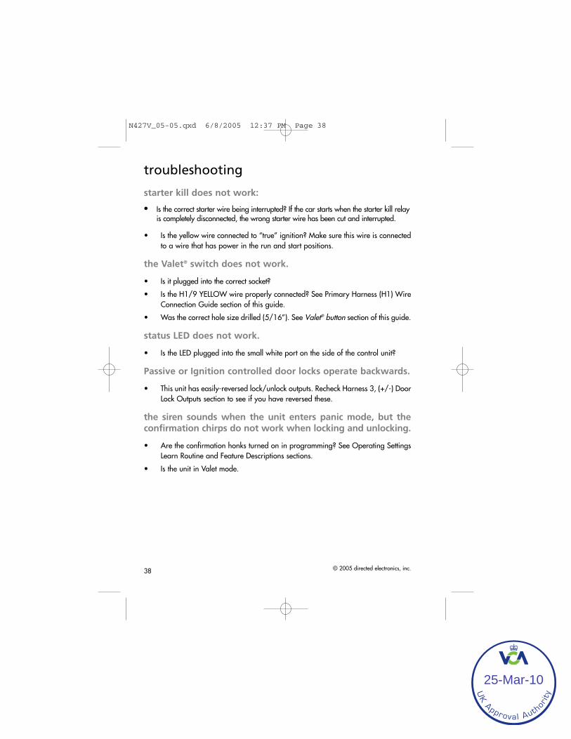
38 © 2005 directed electronics, inc.
troubleshooting
starter kill does not work:
Is the correct starter wire being interrupted? If the car starts when the starter kill relayis completely disconnected, the wrong starter wire has been cut and interrupted.
• Is the yellow wire connected to “true” ignition? Make sure this wire is connectedto a wire that has power in the run and start positions.
the Valet® switch does not work.
• Is it plugged into the correct socket?
• Is the H1/9 YELLOW wire properly connected? See Primary Harness (H1) WireConnection Guide section of this guide.
• Was the correct hole size drilled (5/16”). See Valet® button section of this guide.
status LED does not work.
• Is the LED plugged into the small white port on the side of the control unit?
Passive or Ignition controlled door locks operate backwards.
• This unit has easily-reversed lock/unlock outputs. Recheck Harness 3, (+/-) DoorLock Outputs section to see if you have reversed these.
the siren sounds when the unit enters panic mode, but theconfirmation chirps do not work when locking and unlocking.
• Are the confirmation honks turned on in programming? See Operating SettingsLearn Routine and Feature Descriptions sections.
• Is the unit in Valet mode.
N427V_05-05.qxd 6/8/2005 12:37 PM Page 38
UK Approval Auth
orit
y
25-Mar-10

© 2005 directed electronics, inc. 39
Door Lock Learn Routine does not learn door locks.
• Check connections to be sure everything is properly connected. Refer to the KeylessEntry Systems—Three Types section of this guide for correct wire connections.
• Check the Door Lock Learn Routine section of this guide to ensure the correct pro-cedure is being used.
Door Lock Learn Routine does not work, the unit enters thelearn routine then chirps horn and exits.
• Some cars do not flash the parking lights with the door open. For these vehicles,to program the unit correctly the door needs to be closed (so that the parking lightswill flash with the factory keyless system).
Feature Programming routine does not work, the unit enters thelearn routine then chirps and exits.
• Check the Door Input connections. If the dome light is used for door trigger input,then the dome light must turn off in step 3.
N427V_05-05.qxd 6/8/2005 12:37 PM Page 39
UK Approval Auth
orit
y
25-Mar-10

40 © 2005 directed electronics, inc.
N427V_05-05.qxd 6/8/2005 12:37 PM Page 40
UK Approval Auth
orit
y
25-Mar-10

© 2005 directed electronics, inc. 41
wiring quick reference guide
����������� ���������������������
���������������� �!"�!
#$%�&��'
(���!)*+�!��
(���!)
#�!!��
"!�����*�������"�!
��,-���-������+�����������!"�!
�����.���$�'�!/������!"�!
������#$%�,�/���!���
#$��0�������� ����������'�!��"��1�������!"�!
-���,������!��''����"�!
#$%������!��!!��''��
���.�2 (����!��!"�+��
#� �,.�*������!"�!
3�$$ �.��'��!�����"�!
#$��0���������'�����������!���
(� $��.�����!��''����"�!
��$��
�����
&��'$���
��"!�
#$%���%����45.�$��4
-���,��$��45.�%����4
#� �,���������4��!"�!
-���,�����"�!
�����������/��!��"�!
#$%���������"�!
-��3.�����4����������������"�!
(� $���#$��0,�/���!���
3�$$ ��#$��0$�'�!/��������!����"�!
�����1��
��!�����
"!�����
#�!+��!��
-���,6��7���8
#$%�6��7���8
#$��0������
���.�2 (
��!�����
N427V_05-05.qxd 6/8/2005 12:37 PM Page 41
UK Approval Auth
orit
y
25-Mar-10

N427V_05-05.qxd 6/8/2005 12:37 PM Page 42
UK Approval Auth
orit
y
25-Mar-10

Printed byPrinted onPage
Setup Sheet Information
Associated Part Numbers
Directed Electronics, Inc. ProductionKenny SnoddyDecember 07, 2009
Arena > Workspace Items > Specs > SummaryAll information contained in this document is proprietary and confidential.
(001 - 099) FGI, Finished Good ItemItem #010-0034 In Production
427V, VIPER 330V, OEM UPGRADE SECURITY SYSTEMRevision: Working Revision * | Modified, Shared, 0 Views Locked
SummaryRedline
Category (001 - 099) FGI, Finished Good Item
Item number 010-0034
Revision
Item name 427V, VIPER 330V, OEM UPGRADE SECURITYSYSTEM
Lifecycle phase In Production
Assembly typeHighest accessible assembly
Primary File None specified
Associated Files 0 (plus 0 Supplier Item files)
Description
Owner Kenny Snoddy
Prototype cost $0.00
Production cost $0.00
ProcurementType Made-to-Specification (MTS)
Unit of Measure each
Item Creator Paul Schomberg (Arena)
Item created on October 30, 2007
Barcode ID 0 93207 00855 9
Country of Origin China
M/C l/w/h 16 3/4"x15 1/2"x12 3/4"
M/C Weight (lbs.) 36.45
M/C Quantity 18
Giftbox l/w/h 7 1/2" x 5 1/4" x 4"
Unit Weight (lbs.) 1.95
Pallet Quantity
Brand Number 12
ACCPAC P/N 427V
Arena > Workspace Items > Specs > Summary https://app.bom.com/items/detail‐spec?item_id=8621011&version_i...
1 of 2 12/7/2009 6:39 PM
UK Approval Auth
orit
y
25-Mar-10

Obsolete Attributes
Additional Attributes
Search Field
REV C: D/C 61 10/02/06 ADD EMARK TO CPU HOUSING (ECF7054), -D/C 6C 04/06/06REMOVE ADDENDUM, -D/C 6A 02/21/06 1ST RECEIPT FROM PORTMAN W/ NEWHEX(ECF5845), -D/C 5L 01->02/06,BLUE HI-LITER ON D/C STICKER, PURGE STOCK, FLASHMCU SOFTWARE IS NOW REV D, ADD ADDENDUM (ECF5845)REV B: D/C 5F, 08/01/05,REVISE DIAGRAM IN IG, WAS 01-05 IS 05-05 (ECF5700), -D/C 5C 05/02/05, INCLUDEPORTMAN 514N IN KIT FROM FACTORY, ROLL 100-0081 BOM INTO 010-0034 W/SIREN. M/CQUANTITY WAS 16, IS 18 (ECF5640)REV A: D/C 4L, 01/26/05 (ECF_______), WEIGHTS: 1.40lbs, M/C 24.20 lbs. REWORK 100-0081 TO ADD 100-0049 NUTEK 514N(B) UNTIL PORTMAN514N IS READYFOLDER 401-4040
Team Security
Project
These are attributes that are either no longer used or are migrating to be included into one of theother existing Attributes
Detail
Control Plan
Arena > Workspace Items > Specs > Summary https://app.bom.com/items/detail‐spec?item_id=8621011&version_i...
2 of 2 12/7/2009 6:39 PM
UK Approval Auth
orit
y
25-Mar-10

Printed byPrinted onPage
Directed Electronics, Inc. ProductionKenny SnoddyDecember 07, 2009
Arena > Workspace Items > Bill of Materials > IndentedAll information contained in this document is proprietary and confidential.
(001 - 099) FGI, Finished Good ItemItem #010-0034 In Production
427V, VIPER 330V, OEM UPGRADE SECURITY SYSTEMRevision: Working Revision * | Modified, Shared, 0 Views Locked
Contains 12 first-level Items, 55 line Items, 55 unique Items
# Item Number Item Name Category PhaseWkg
Mods FilesRqmtsQty
1 100-0082(A) 514N, 6 TONE, NEO, SOFT CHIRP,PM (100 - 119) KittedAssembly
In Prod 1 each
2 100-0150(A) 427V HARNESS KIT (100 - 119) KittedAssembly
In Prod 1 each
1 150-0191(A) HRN, 2-WIRE, DUAL DIODE ISOLATEDLIGHT FLASH 1-WIRE/2-WIRE, UNFUSED
(150) Harnessand Cables
In Prod 2 1 each
2 150-0222(A) HRN, LED, 2.50MM 2-PIN, 2-WIRE, CON/BLUE LED, BLUE DIFFUSER
(150) Harnessand Cables
In Prod 2 1 each
3 150-0223(A) HRN, SWITCH, 2.50MM, 2-PIN,2-WIRE,VALET SW, MOMENTARY, SNAP FIT,BLUE CON/ SW
(150) Harnessand Cables
In Prod 2 1 each
4 150-0232(A) HRN, 2.50MM, 3-PIN, 2-WIRE, WHITECON/WIRE
(150) Harnessand Cables
In Prod 2 1 each
5 150-0235(A) HRN,2.0MM,4-PIN,4-WIRE WHITECON/WIRE
(150) Harnessand Cables
In Prod 2 1 each
6 150-0236(A) HRN,2.50MM,7-PIN,7-WIRE WHITECON/WIRE
(150) Harnessand Cables
In Prod 2 1 each
7 150-0248(A) HRN,DOOR UNLOCK PULSE ADAPTER (150) Harnessand Cables
In Prod 2 1 each
3 121-0112(D) VIPER 330V CONTROL MODULE,SERIALIZED, OEM UPGRADE
(120 - 149) FinalAssembly
In Prod 1 each
1 170-0021(G) PCBA, CTRL, 427, W/SHOCK, (170) PCBAssembly
In Prod 2 1 each
2 450-0036(A) HDW, SCREW, PANHEAD, PHILLIPS,BLACK, M3
(450 - 490)Hardware
In Prod 4 each
3 530-0011(A) LBL, TAMPER-PROOF DATE CODELABEL, RECTANGULAR
(500 - 599)Printed Materials
In Prod 2 1 each
4 530-0069(A) LABEL, SERIAL NUMBER, 427V (500 - 599)Printed Materials
In Prod 1 each
5 620-0272-02(A) PLASTIC HOUSING, CPU TOP, 427,436 (600 - 690)Mechanical
In Prod 2 1 each
6 620-0273-01(B) PLASTIC HOUSING, CPU BOTTOM,427,436
(600 - 690)Mechanical
In Prod 2 1 each
7 620-0274-01(A) PLASTIC SLIDE DOOR, CPU, 427,436 (600 - 690)Mechanical
In Prod 2 1 each
8 670-0009-02(A) GEL BADGE, ROUND, 28MM, VIPER, PM (600 - 690)Mechanical
In Prod 2 1 each
4 150-0189(E) HRN, 3.96MM, 12-POS, 12-WIRE, FUSEDW/STARTER KILL, CON/WIRE, W/UNFUSED LIGHT FLASH WIRE
(150) Harnessand Cables
In Prod 2 1 each
5 500-0108(01-05) OG, G427V, VIPER, 330V, OWNERSGUIDE
(500 - 599)Printed Materials
In Prod 1 1 each
6 510-0127(05-05) IG, VIPER, 330V, INSTALLATION GUIDE (500 - 599)Printed Materials
In Prod 1 1 each
7 520-0099(11-04) GB, VIPER, 330V, GIFTBOX (500 - 599)Printed Materials
In Prod 1 each
8 530-0062(A) LBL, VIPER WINDOW DECAL, NOPHONE NUMBER
(500 - 599)Printed Materials
In Prod 2 2 each
9 540-0058(07-00) INSERT, PATENT CARD, w/ QUALITY BYDESIGN BACKGROUND
(500 - 599)Printed Materials
In Prod 1 1 each
10 540-0070(04/14/09) INS, XFJ01-01, SECURITY RESPONSECARD INSERT
(500 - 599)Printed Materials
In Prod 1 1 each
Arena > Workspace Items > Bill of Materials > Indented https://app.bom.com/items/detail‐bom‐nested?item_id=8621011&ve...
1 of 2 12/7/2009 6:40 PM
UK Approval Auth
orit
y
25-Mar-10

# Item Number Item Name Category PhaseWkg
Mods FilesRqmtsQty
11 901-10036(2.4) ENGINEERING PRODUCTSPECIFICATION, 427M, 2003
-uncategorized- In Prod 1 1 each
12 910-0014(4) CONTROL PLAN, SNTX/RX-1 (900 - 999)Document
In Prod 1 1 each
Arena > Workspace Items > Bill of Materials > Indented https://app.bom.com/items/detail‐bom‐nested?item_id=8621011&ve...
2 of 2 12/7/2009 6:40 PM
UK Approval Auth
orit
y
25-Mar-10
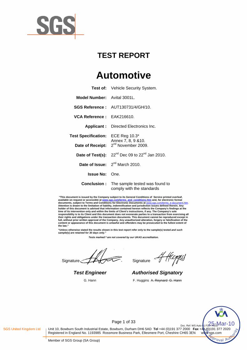
Page 1 of 33 Doc. Ref: WS Auto 01 F10 I Rev2
SGS United Kingdom Ltd Unit 10, Bowburn South Industrial Estate, Bowburn, Durham DH6 5AD Tel +44 (0)191 377 2000 Fax +44 (0)191 377 2020 Registered in England No. 1193985 Rossmore Business Park, Ellesmere Port, Cheshire CH65 3EN www.sgs.com
Member of SGS Group (SA Group)
TEST REPORT
Automotive
Test of: Vehicle Security System.
Model Number: Avital 3001L.
SGS Reference : AUT130731/4/GH/10.
VCA Reference : EAK216610.
Applicant : Directed Electronics Inc.
Test Specification: ECE Reg 10.3* Annex 7, 8, 9 &10.
Date of Receipt: 2nd November 2009.
Date of Test(s): 22nd Dec 09 to 22nd Jan 2010.
Date of Issue: 2nd March 2010.
Issue No: One.
Conclusion : The sample tested was found to comply with the standards
“This document is issued by the Company subject to its General Conditions of Service printed overleaf, available on request or accessible at www.sgs.com/terms_and_conditions.htm and, for electronic format documents, subject to Terms and Conditions for Electronic Documents at www.sgs.com/terms_e-document.htm. Attention is drawn to the limitation of liability, indemnification and jurisdiction issues defined therein. Any holder of this document is advised that information contained hereon reflects the Company’s findings at the time of its intervention only and within the limits of Client’s instructions, if any. The Company’s sole responsibility is to its Client and this document does not exonerate parties to a transaction from exercising all their rights and obligations under the transaction documents. This document cannot be reproduced except in full, without prior written approval of the Company. Any unauthorized alteration, forgery or falsification of the content or appearance of this document is unlawful and offenders may be prosecuted to the fullest extent of the law.” “Unless otherwise stated the results shown in this test report refer only to the sample(s) tested and such sample(s) are retained for 30 days only.”
Tests marked:* are not covered by our UKAS accreditation.
Signature Signature
Test Engineer Authorised Signatory G. Hann F. Huggins A. Reynard G. Hann
UK Approval Auth
orit
y
25-Mar-10

TEST REPORT Page 2 of 33
Issue Date: 2nd March 2010. SGS Serial Number:
AUT130731/4/GH/10.
CONTENTS Page Number
1. Client Information ...........................................................................................................................3
2. Equipment Under Test (EUT) .........................................................................................................3 2.1 Identification of EUT.......................................................................................................................................................3
3. Test Specification, Methods and Procedures ..............................................................................4 3.1 ) Purpose of Test ........................................................................................................................................................4
4. Deviations or Exclusions from the Test Specifications..............................................................4
5. Operation of the EUT During Testing ...........................................................................................4 5.1 Configuration and Peripherals........................................................................................................................................4 5.2 Operating Mode and Environmental Conditions .............................................................................................................4
6. Test Results.....................................................................................................................................5
UK Approval Auth
orit
y
25-Mar-10

TEST REPORT Page 3 of 33
Issue Date: 2nd March 2010. SGS Serial Number:
AUT130731/4/GH/10.
1. Client Information
Company Name: Directed Electronics Inc. Address:
1 Viper Way, Vista, CA. 92081, USA.
Contact Name: (UK) Carl Huntington Telephone: +(44) 7884 312 279 Facsimile: N/A.
2. Equipment Under Test (EUT) 2.1 Identification of EUT
Model Number: Avital 3001L Unique Identifier: 093207064791 [Marked on box] Description of EUT: Vehicle security system with siren 514M,
door/boot/bonnet/Ign sensors, OEM system using vehicle remotes.
Supply Voltage: 12 VDC. Accessories Supplied: None.
UK Approval Auth
orit
y
25-Mar-10

TEST REPORT Page 4 of 33
Issue Date: 2nd March 2010. SGS Serial Number:
AUT130731/4/GH/10.
3. Purpose of Tests
To perform the relevant tests and assess the product for compliance with the above specification. 4. Deviations or Exclusions from the Test Specifications
There were no deviations from the test specifications.
The scope of the inspection is limited to what is specified in the clients instructions and does not include any other checks or tests.
5. Operation of the EUT During Testing
5.1 Configuration and Peripherals
Peripheral or support equipment was required for the tests. (LEDs were connected for monitoring state changes).
5.2 Operating Mode and Environmental Conditions
The operating modes and environmental conditions used for each individual test are described in the test results section of this report.
UK Approval Auth
orit
y
25-Mar-10

TEST REPORT Page 5 of 33
Issue Date: 2nd March 2010. SGS Serial Number:
AUT130731/4/GH/10.
6. Test Results 1 Test Specification 2004/104/EC: 2004, as amended by 2005/83/EC / 2006/28/EC. ECE Reg 10.3. 2 Purpose of Test
To perform the relevant tests and assess the product for compliance with the above specification.
3 Methods and Procedures. The following tests are called up by the test specification:-
Standard
Date Description Applicable
2004/104/ECECE Reg 10.3
2004.
Narrowband Emissions.
Yes
2004/104/ECECE Reg 10.3
2004 Broadband Emissions
Yes
2004/104/ECECE Reg 10.3
2004 Radiated Immunity
Yes
ISO 7637 – 2
[2004/104/EC Reg 10.3]
2004 Transient conduction along supply lines. Yes
ISO 7637 – 2
[2004/104/EC Reg 10.3]
2004 Voltage transient emissions
Yes
UK Approval Auth
orit
y
25-Mar-10

TEST REPORT Page 6 of 33
Issue Date: 2nd March 2010. SGS Serial Number:
AUT130731/4/GH/10.
Operation of E.U.T. During Testing Operating Environment
Power Supply: Volts 12 – 13.5 DC.
Environmental conditions:- Temperature: oC 18.5 – 19 Relative Humidity: % 39 - 48 Barometric Pressure: mbar 965 - 1009 Configuration & Peripherals
Peripherals were attached to the EUT during testing. LED,s were connected to monitor state changes.
UK Approval Auth
orit
y
25-Mar-10

TEST REPORT Page 7 of 33
Issue Date: 2nd March 2010. SGS Serial Number:
AUT130731/4/GH/10.
Photograph of the EUT.
UK Approval Auth
orit
y
25-Mar-10

TEST REPORT Page 8 of 33
Issue Date: 2nd March 2010. SGS Serial Number:
AUT130731/4/GH/10.
Summary of Test Results
Standard
Test Result
2004/104/ECECE Reg 10.3
Annex VIII
Narrowband Emissions
Complied
2004/104/ECECE Reg 10.3
Annex VII
Broadband Emissions
Complied
2004/104/ECECE Reg 10.3
Annex IX
Radiated Immunity Complied
2004/104/ECECE Reg 10.3
Annex X
Transient Pulses Complied
2004/104/ECECE Reg 10.3
Annex X
Transient Emissions Complied
Result In the configuration tested the EUT complied with the specification.
UK Approval Auth
orit
y
25-Mar-10

TEST REPORT Page 9 of 33
Issue Date: 2nd March 2010. SGS Serial Number:
AUT130731/4/GH/10.
Test Results General Comments Details of the test methods used can be found in the SGS EMC procedures manual. Modifications Made to the EUT. No modifications were made to the EUT. RADIATED EMISSIONS OPERATING MODE Tested in two modes – Armed-set and disarmed ignition on drive mode. NARROWBAND & BROADBAND EMISSIONS Tests were carried out in the vertical and horizontal antenna polarisation, for the above operating mode within an enclosed anechoic chamber. EQUIPMENT USED. 1. Rohde & Schwarz Rxer. Ser. No. 825892/019 2. Automotive LISN. 3. Antennas Chase VBA & EMCO 3146. PERFORMANCE CRITERIA All emissions are at least 2 dB below the reference limits for the Vehicle Certification Agency approval.
UK Approval Auth
orit
y
25-Mar-10

TEST REPORT Page 10 of 33
Issue Date: 2nd March 2010. SGS Serial Number:
AUT130731/4/GH/10.
Test Configuration Radiated Emissions:
UK Approval Auth
orit
y
25-Mar-10

TEST REPORT Page 11 of 33
Issue Date: 2nd March 2010. SGS Serial Number:
AUT130731/4/GH/10.
VER. POL. SCAN: 22 Dec 2009 08:58 J-FILE 130731/1. VER. POL. PEAK SCAN. Avital 3001L. Directed Electronics Inc. 13.5 volts DC supply, disarmed Ign on. G.H. Reg 10.3. Start Stop Freq Step IFBW Detector M-Time Atten PreAmp OpRge 30MHz 1000MHz 60kHz 120kHz PK 2msec 0 dB OFF 60dB
UK Approval Auth
orit
y
25-Mar-10

TEST REPORT Page 12 of 33
Issue Date: 2nd March 2010. SGS Serial Number:
AUT130731/4/GH/10.
VER. POL. SCAN: 22 Dec 2009 09:20 J-FILE 130731/1. VER. POL. PEAK SCAN. Avital 3001L. Directed Electronics Inc. 12 volts DC supply, armed mode. G.H. Reg 10.3. Start Stop Freq Step IFBW Detector M-Time Atten PreAmp OpRge 30MHz 1000MHz 60kHz 120kHz PK 2msec 0 dB OFF 60dB
UK Approval Auth
orit
y
25-Mar-10

TEST REPORT Page 13 of 33
Issue Date: 2nd March 2010. SGS Serial Number:
AUT130731/4/GH/10.
HOR. POL. SCAN: 22 Dec 2009 09:11 J-FILE 130731/1. HOR. POL. PEAK SCAN. Avital 3001L. Directed Electronics Inc. 13.5 volts DC supply, disarmed Ign on. G.H. Reg 10.3. Start Stop Freq Step IFBW Detector M-Time Atten PreAmp OpRge 30MHz 1000MHz 60kHz 120kHz PK 2msec 0 dB OFF 60dB
UK Approval Auth
orit
y
25-Mar-10

TEST REPORT Page 14 of 33
Issue Date: 2nd March 2010. SGS Serial Number:
AUT130731/4/GH/10.
HOR. POL. SCAN: 22 Dec 2009 09:32 J-FILE 130731/1. HOR. POL. PEAK SCAN. Avital 3001L. Directed Electronics Inc. 12 volts DC supply, armed mode. G.H. Reg 10.3. Start Stop Freq Step IFBW Detector M-Time Atten PreAmp OpRge 30MHz 1000MHz 60kHz 120kHz PK 2msec 0 dB OFF 60dB
UK Approval Auth
orit
y
25-Mar-10

TEST REPORT Page 15 of 33
Issue Date: 2nd March 2010. SGS Serial Number:
AUT130731/4/GH/10.
RADIATED IMMUNITY OPERATING MODE 13.5 VDC supply ignition on drive mode. IMMUNITY TESTING 20 to 2000MHz [30 V/m] 20 to 800MHz with [1 kHz 80% AM] modulation 800 to 2000MHz with [pulsed “t on 577µsec, period 4600 µsec”] modulation Dwell time: Two seconds. Tests were carried out in the above operating mode, NB. In the anechoic chamber the antenna was in the vertical / horizontal polarisation. EQUIPMENT USED. Amplifier 250L Amplifier 500W1000A Amplifier 200T1G3A Signal generator 2024 Isotropic field monitor FM Radi-Sense RI-37 Probe FP 04 RI-37 Power Meter NVRS Functional Generator TG 1010 Spectrum Analyser HP8563E Auto LISN NNBM PERFORMANCE CRITERIA The EUT shall not exhibit any malfunction which will cause any degradation of performance which could cause confusion to other road users or any degradation in the driver's direct control of a vehicle fitted with the system which could be observed by the driver or other road user.
UK Approval Auth
orit
y
25-Mar-10

TEST REPORT Page 16 of 33
Issue Date: 2nd March 2010. SGS Serial Number:
AUT130731/4/GH/10.
Test Configuration Radiated Immunity:
UK Approval Auth
orit
y
25-Mar-10

TEST REPORT Page 17 of 33
Issue Date: 2nd March 2010. SGS Serial Number:
AUT130731/4/GH/10.
20 to 200 MHz V-Pol.
20M
Hz
to 2
00M
Hz
E/e
(20
MH
z -
200
MH
z)
Auto-e-V-Pol. 20 to 200MHz 30V/m.
20M 100M 200MFrequency (MHz)
-80
-71.05
-62.1
-53.15
-44.2
-35.25
-26.3
-17.35
-8.4
0.55
9.5
DR
IVE
LE
VE
L (d
Bm
)
-10
-4
2
8
14
20
26
32
38
44
50
F-P
WR
(dB
m)
0
10
20
30
40
50
60
70
80
90
100
ES
T S
TR
ES
S (
V/m
)
0
50
100
150
200
250
300
350
400
450
500
NE
T-P
WR
(W
)
20 to 200 MHz H-Pol.
20M
Hz
to 2
00M
Hz
E/e
(20
MH
z -
200
MH
z)
Auto-e-H-Pol. 20 to 200MHz 30V/m.
20M 100M 200MFrequency (MHz)
-80
-72.05
-64.1
-56.15
-48.2
-40.25
-32.3
-24.35
-16.4
-8.45
-0.5
DR
IVE
LE
VE
L (d
Bm
)
-10
-4
2
8
14
20
26
32
38
44
50
F-P
WR
(dB
m)
0
10
20
30
40
50
60
70
80
90
100
ES
T S
TR
ES
S (
V/m
)
0
50
100
150
200
250
300
350
400
450
500
NE
T-P
WR
(W
)
UK Approval Auth
orit
y
25-Mar-10

TEST REPORT Page 18 of 33
Issue Date: 2nd March 2010. SGS Serial Number:
AUT130731/4/GH/10.
200 to 2000 MHz V-Pol.
AUTO-E-V-POL 30V/m. 200MHz to 2GHz.
200M 1G 2GFrequency (MHz)
-80
-72.05
-64.1
-56.15
-48.2
-40.25
-32.3
-24.35
-16.4
-8.45
-0.5
DR
IVE
LE
VE
L (d
Bm
)
0
10
20
30
40
50
60
70
80
90
100
ST
RE
SS
(V
/m)
0
50
100
150
200
250
300
350
400
450
500
NE
T-P
WR
(W
)
0
10
20
30
40
50
60
70
80
90
100
ES
T S
TR
ES
S (
V/m
)
-30
-22
-14
-6
2
10
18
26
34
42
50
F-P
WR
(dB
m)
200 to 2000 MHz H-Pol.
AUTO-E-H-POL 30V/m. 200MHz to 2GHz.
200M 1G 2GFrequency (MHz)
-80
-72.05
-64.1
-56.15
-48.2
-40.25
-32.3
-24.35
-16.4
-8.45
-0.5
DR
IVE
LE
VE
L (d
Bm
)
0
10
20
30
40
50
60
70
80
90
100
ST
RE
SS
(V
/m)
0
50
100
150
200
250
300
350
400
450
500
NE
T-P
WR
(W
)
0
10
20
30
40
50
60
70
80
90
100
ES
T S
TR
ES
S (
V/m
)
-40
-31
-22
-13
-4
5
14
23
32
41
50
F-P
WR
(dB
m)
UK Approval Auth
orit
y
25-Mar-10

TEST REPORT Page 19 of 33
Issue Date: 2nd March 2010. SGS Serial Number:
AUT130731/4/GH/10.
1000 to 2000 MHz V-Pol.
AUTO-E-V-POL 30V/m. 1 - 2GHz.
1G 2GFrequency (MHz)
-80
-72.05
-64.1
-56.15
-48.2
-40.25
-32.3
-24.35
-16.4
-8.45
-0.5
DR
IVE
LE
VE
L (d
Bm
)
0
10
20
30
40
50
60
70
80
90
100
ST
RE
SS
(V
/m)
-20
-13
-6
1
8
15
22
29
36
43
50
F-P
WR
(dB
m)
0
10
20
30
40
50
60
70
80
90
100
ES
T S
TR
ES
S (
V/m
)
0
10
20
30
40
50
60
70
80
90
100
TA
RG
ET
ST
RE
SS
(V
/m)
0
50
100
150
200
250
300
350
400
450
500
NE
T-P
WR
(W
)
1000 to 2000 MHz H-Pol
AUTO-E-H-POL 30V/m. 1 - 2GHz.
1G 2GFrequency (MHz)
-80
-72.05
-64.1
-56.15
-48.2
-40.25
-32.3
-24.35
-16.4
-8.45
-0.5
DR
IVE
LE
VE
L (d
Bm
)
0
10
20
30
40
50
60
70
80
90
100
ST
RE
SS
(V
/m)
-20
-13
-6
1
8
15
22
29
36
43
50
F-P
WR
(dB
m)
0
10
20
30
40
50
60
70
80
90
100
ES
T S
TR
ES
S (
V/m
)
0
10
20
30
40
50
60
70
80
90
100
TA
RG
ET
ST
RE
SS
(V
/m)
0
50
100
150
200
250
300
350
400
450
500
NE
T-P
WR
(W
)
UK Approval Auth
orit
y
25-Mar-10

TEST REPORT Page 20 of 33
Issue Date: 2nd March 2010. SGS Serial Number:
AUT130731/4/GH/10.
Transient Immunity OPERATING MODE Ignition on drive mode. Immunity Pulses 12 volt systems
Pulse Number.
Test Level Number of pulse / time.
Pass / Fail
1.
-75V 5000 B
2a
+37V 5000 A
2b
+10V 10 B
3a
-112V 1 hour A
3b
+75V 1 hour A
4
-6V 1 pulse A
EQUIPMENT USED. Pulse generators: NSG 5500, MT 5511, FT 5530, LD 5505, NSG 5004, NSG 5201, INA 5002, INA 5025, INA 5026, DCS 5230, ARB 5220, CTR 5210. Oscilloscope – Agilent: 54810A
UK Approval Auth
orit
y
25-Mar-10

TEST REPORT Page 21 of 33
Issue Date: 2nd March 2010. SGS Serial Number:
AUT130731/4/GH/10.
Test Configuration Transient Immunity:
UK Approval Auth
orit
y
25-Mar-10

TEST REPORT Page 22 of 33
Issue Date: 2nd March 2010. SGS Serial Number:
AUT130731/4/GH/10.
Test Report
Date: 01-14-2010 Time: 12:38:06
AUT: 130731/1.
Company Name : Directed Electronics Inc.
Equipment Tested : Avital 3001L.
Serial Number : Not marked.
Test Equipment used : TESEQ Generators
Test Procedure Used : ISO 7637 - 2.
General Conditions Ambient Temperature : 19 Humidity : 48 Pressure : 986 Tested by : G. Hann. Signature :
Test Number 1 Test Name 12vp1. Test Type MT 5511 Pulse 1 Sequence Repetition Count 5000
Test Status PASS. B.
US
UA
0
t3
t2
t1
V
t
td
90%
10%
- +
EU
T
Parameter Operation From To Step Size Fail Value Pulse Voltage (Us) Static 75 V --- --- --- Pulse Period (t1) Static 0.5 s --- --- --- General Value Rise Time (tr) 1 us Output Resistance (Ri) 10 ohms Pulse Width (td) 2 ms t2 200 ms Polarity/Coupling Negative Parallel Battery Battery State UPC/Time Voltage 13.5 V Current Limit 12.5 A End of Test Voltage 13.5 V Comments During the test the Supply – flickered on/off, then returned to normal on completion of the test.
UK Approval Auth
orit
y
25-Mar-10

TEST REPORT Page 23 of 33
Issue Date: 2nd March 2010. SGS Serial Number:
AUT130731/4/GH/10.
Test Report
Date: 01-14-2010 Time: 13:34:51
AUT: 130731/1.
Company Name : Directed Electronics Inc.
Equipment Tested : Avital 3001L.
Serial Number : Not marked.
Test Equipment used : TESEQ Generators
Test Procedure Used : ISO 7637 - 2.
General Conditions Ambient Temperature : 19 Humidity : 48 Pressure : 986 Tested by : G. Hann. Signature :
Test Number 1 Test Name 12vp2a. Test Type MT 5511 Pulse 2 Sequence Repetition Count 5000
Test Status PASS. A. US
UA
0V
t1
10%
90%
td
tr
- +
EU
T
Parameter Operation From To Step Size Fail Value Pulse Voltage (Us) Static 37 V --- --- --- Pulse Period (t1) Static 0.2 s --- --- --- General Value Rise Time (tr) 1 us Output Resistance (Ri) 2 ohms Pulse Width (td) 50 us t2 Not Applicable Polarity/Coupling Positive Serial Battery Battery State On Voltage 13.5 V Current Limit 12.5 A End of Test Voltage 13.5 V Ext. Resistance (Ri) External Resistance Inactive Comments No changes recorded.
UK Approval Auth
orit
y
25-Mar-10

TEST REPORT Page 24 of 33
Issue Date: 2nd March 2010. SGS Serial Number:
AUT130731/4/GH/10.
Test Report
Date: 01-14-2010 Time: 13:47:46
AUT: 130731/1.
Company Name : Directed Electronics Inc.
Equipment Tested : Avital 3001L.
Serial Number : Not marked.
Test Equipment used : TESEQ Generators
Test Procedure Used : ISO 7637 - 2.
General Conditions Ambient Temperature : 19 Humidity : 48 Pressure : 986 Tested by : G. Hann. Signature :
Test Number 1 Test Name 12vp2b. Test Type NSG 5200 Pulse 2B Sequence Repetition Count 10
Test Status PASS. B.
t6
10%
90%
td
tr
tf
0V
t2
US
UA
Voltage Ua 12 V Us 10 V Timing tf 1 ms t6 1 ms tr 1 ms td 50 ms t2 0.5 s t1 2 s Resistance Resistance 0 ohms Battery Current Limit 12 A End of Test Voltage 13.5 V Comments The supply flickered off/on with each pulse applied.
UK Approval Auth
orit
y
25-Mar-10

TEST REPORT Page 25 of 33
Issue Date: 2nd March 2010. SGS Serial Number:
AUT130731/4/GH/10.
Test Report
Date: 01-14-2010 Time: 14:53:05
AUT: 130731/1.
Company Name : Directed Electronics Inc.
Equipment Tested : Avital 3001L.
Serial Number : Not marked.
Test Equipment used : TESEQ Generators
Test Procedure Used : ISO 7637 - 2.
General Conditions Ambient Temperature : 19 Humidity : 48 Pressure : 986 Tested by : G. Hann. Signature :
Test Number 1 Test Name 12vp3a. Test Type FT 5530 Pulse 3A Sequence Repetition Hours 1
Test Status PASS. A.
US
UA
0V
t1t4 t5
Vt
Parameter Operation From To Step Size Fail Value Pulse Voltage (Us) Static 112 V --- --- --- Pulse Freq (1/t1) Static 10 kHz --- --- --- General Value Rise Time (tr) 5 ns Output Resistance (Ri) 50 ohms Pulse Width (td) 100 ns Burst Interval(t5) 0.09 s Output Mode NORMAL No Pulses (t4/t1) Burst Duration (t4) 10 ms Battery Battery State On Voltage 12 V Current Limit 12 A End of Test Voltage 12 V Polarity Polarity Negative Comments No changes recorded.
UK Approval Auth
orit
y
25-Mar-10

TEST REPORT Page 26 of 33
Issue Date: 2nd March 2010. SGS Serial Number:
AUT130731/4/GH/10.
Test Report
Date: 01-14-2010 Time: 16:01:39
AUT: 130731/1.
Company Name : Directed Electronics Inc.
Equipment Tested : Avital 3001L.
Serial Number : Not marked.
Test Equipment used : TESEQ Generators
Test Procedure Used : ISO 7637 - 2.
General Conditions Ambient Temperature : 19 Humidity : 48 Pressure : 986 Tested by : G. Hann. Signature :
Test Number 1 Test Name 12vp3b. Test Type FT 5530 Pulse 3B Sequence Repetition Hours 1
Test Status PASS. A. US
UA
0V
t1
t4 t5V
t
Parameter Operation From To Step Size Fail Value Pulse Voltage (Us) Static 75 V --- --- --- Pulse Freq (1/t1) Static 10 kHz --- --- --- General Value Rise Time (tr) 5 ns Output Resistance (Ri) 50 ohms Pulse Width (td) 100 ns Burst Interval(t5) 0.09 s Output Mode NORMAL No Pulses (t4/t1) Burst Duration (t4) 10 ms Battery Battery State On Voltage 13.5 V Current Limit 12 A End of Test Voltage 13.5 V Polarity Polarity Positive Comments No changes recorded.
UK Approval Auth
orit
y
25-Mar-10

TEST REPORT Page 27 of 33
Issue Date: 2nd March 2010. SGS Serial Number:
AUT130731/4/GH/10.
Test Report
Date: 01-14-2010 Time: 16:19:22
AUT: 130731/1.
Company Name : Directed Electronics Inc.
Equipment Tested : Avital 3001L.
Serial Number : Not marked.
Test Equipment used : TESEQ Generators
Test Procedure Used : ISO 7637 - 2.
Test Number 1 Test Name 12vp4. Test Type Pulse 4 Sequence Repetition Count 1 Test Status PASS. A.
Segment Number # 1 RAMP
Parameter Mode Initial Value Final Value Amplitude Static 12 Vpp - - - Parameter Value Segment Duration 100 ms
Segment Number # 2 RAMP
Parameter Mode Initial Value Final Value Amplitude Linear 12 Vpp 6 Vpp Parameter Value Segment Duration 5 ms
Segment Number # 3 RAMP
Parameter Mode Initial Value Final Value Amplitude Static 6 Vpp - - - Parameter Value Segment Duration 15 ms
Segment Number # 4 RAMP
Parameter Mode Initial Value Final Value Amplitude Linear 6 Vpp 8 Vpp Parameter Value
UK Approval Auth
orit
y
25-Mar-10

TEST REPORT Page 28 of 33
Issue Date: 2nd March 2010. SGS Serial Number:
AUT130731/4/GH/10.
Segment Duration 50 ms
Segment Number # 5 RAMP
Parameter Mode Initial Value Final Value Amplitude Static 8 Vpp - - - Parameter Value Segment Duration 5 Seconds
Segment Number # 6 RAMP
Parameter Mode Initial Value Final Value Amplitude Linear 8 Vpp 12 Vpp Parameter Value Segment Duration 5 ms
Segment Number # 7 RAMP
Parameter Mode Initial Value Final Value Amplitude Static 12 Vpp - - - Parameter Value Segment Duration 100 ms Battery: End of Test: Current Limit: 12.5 A Voltage: 12 V Comments No changes recorded. General Conditions Ambient Temperature : 19 Humidity : 48 Pressure : 986 Tested by : G. Hann. Signature :
UK Approval Auth
orit
y
25-Mar-10

TEST REPORT Page 29 of 33
Issue Date: 2nd March 2010. SGS Serial Number:
AUT130731/4/GH/10.
Transient Emissions OPERATING MODE Ignition on – disarmed. Emissions Pulse maximum amplitude 12 volt systems
Pulse polarity.
Maximum Level Pass / Fail
Positive
+75V Pass
Negative
-100V Pass
EQUIPMENT USED. TESEQ: AES 5501 Automotive emissions system. 1 – SC 5501 “Control” (85-264-VAC) S/No. 1013. 2 – AN 5501 “LISN” (1000008) S/No. 1013. 3 – ES 5501 “Electronic switch” (202-150) S/No. 1013. 4 – MS 5501 “Mechanical switch” (202-160) S/No. 1013. Scope – Agilent 54810A. S/No. US40110227.
UK Approval Auth
orit
y
25-Mar-10

TEST REPORT Page 30 of 33
Issue Date: 2nd March 2010. SGS Serial Number:
AUT130731/4/GH/10.
Test Configuration Transient Emission:
UK Approval Auth
orit
y
25-Mar-10

TEST REPORT Page 31 of 33
Issue Date: 2nd March 2010. SGS Serial Number:
AUT130731/4/GH/10.
12V Switching on.
UK Approval Auth
orit
y
25-Mar-10

TEST REPORT Page 32 of 33
Issue Date: 2nd March 2010. SGS Serial Number:
AUT130731/4/GH/10.
12V Switching off.
UK Approval Auth
orit
y
25-Mar-10

TEST REPORT Page 33 of 33
Issue Date: 2nd March 2010. SGS Serial Number:
AUT130731/4/GH/10.
Blank Page
Last Page of Report
UK Approval Auth
orit
y
25-Mar-10